EP3207913B1 - Assembly and system for distractor and/or positioner - Google Patents
Assembly and system for distractor and/or positioner Download PDFInfo
- Publication number
- EP3207913B1 EP3207913B1 EP17155968.5A EP17155968A EP3207913B1 EP 3207913 B1 EP3207913 B1 EP 3207913B1 EP 17155968 A EP17155968 A EP 17155968A EP 3207913 B1 EP3207913 B1 EP 3207913B1
- Authority
- EP
- European Patent Office
- Prior art keywords
- patient
- assembly
- pad
- support bar
- enclosure
- Prior art date
- Legal status (The legal status is an assumption and is not a legal conclusion. Google has not performed a legal analysis and makes no representation as to the accuracy of the status listed.)
- Active
Links
Images



Classifications
-
- A—HUMAN NECESSITIES
- A61—MEDICAL OR VETERINARY SCIENCE; HYGIENE
- A61G—TRANSPORT, PERSONAL CONVEYANCES, OR ACCOMMODATION SPECIALLY ADAPTED FOR PATIENTS OR DISABLED PERSONS; OPERATING TABLES OR CHAIRS; CHAIRS FOR DENTISTRY; FUNERAL DEVICES
- A61G13/00—Operating tables; Auxiliary appliances therefor
- A61G13/10—Parts, details or accessories
- A61G13/12—Rests specially adapted therefor; Arrangements of patient-supporting surfaces
- A61G13/1205—Rests specially adapted therefor; Arrangements of patient-supporting surfaces for specific parts of the body
- A61G13/1245—Knees, upper or lower legs
-
- A—HUMAN NECESSITIES
- A61—MEDICAL OR VETERINARY SCIENCE; HYGIENE
- A61F—FILTERS IMPLANTABLE INTO BLOOD VESSELS; PROSTHESES; DEVICES PROVIDING PATENCY TO, OR PREVENTING COLLAPSING OF, TUBULAR STRUCTURES OF THE BODY, e.g. STENTS; ORTHOPAEDIC, NURSING OR CONTRACEPTIVE DEVICES; FOMENTATION; TREATMENT OR PROTECTION OF EYES OR EARS; BANDAGES, DRESSINGS OR ABSORBENT PADS; FIRST-AID KITS
- A61F5/00—Orthopaedic methods or devices for non-surgical treatment of bones or joints; Nursing devices ; Anti-rape devices
- A61F5/37—Restraining devices for the body or for body parts; Restraining shirts
- A61F5/3761—Restraining devices for the body or for body parts; Restraining shirts for attaching the limbs to other objects
-
- A—HUMAN NECESSITIES
- A61—MEDICAL OR VETERINARY SCIENCE; HYGIENE
- A61G—TRANSPORT, PERSONAL CONVEYANCES, OR ACCOMMODATION SPECIALLY ADAPTED FOR PATIENTS OR DISABLED PERSONS; OPERATING TABLES OR CHAIRS; CHAIRS FOR DENTISTRY; FUNERAL DEVICES
- A61G13/00—Operating tables; Auxiliary appliances therefor
- A61G13/0036—Orthopaedic operating tables
- A61G13/0063—Orthopaedic operating tables specially adapted for knee surgeries
-
- A—HUMAN NECESSITIES
- A61—MEDICAL OR VETERINARY SCIENCE; HYGIENE
- A61G—TRANSPORT, PERSONAL CONVEYANCES, OR ACCOMMODATION SPECIALLY ADAPTED FOR PATIENTS OR DISABLED PERSONS; OPERATING TABLES OR CHAIRS; CHAIRS FOR DENTISTRY; FUNERAL DEVICES
- A61G13/00—Operating tables; Auxiliary appliances therefor
- A61G13/10—Parts, details or accessories
- A61G13/101—Clamping means for connecting accessories to the operating table
-
- A—HUMAN NECESSITIES
- A61—MEDICAL OR VETERINARY SCIENCE; HYGIENE
- A61G—TRANSPORT, PERSONAL CONVEYANCES, OR ACCOMMODATION SPECIALLY ADAPTED FOR PATIENTS OR DISABLED PERSONS; OPERATING TABLES OR CHAIRS; CHAIRS FOR DENTISTRY; FUNERAL DEVICES
- A61G13/00—Operating tables; Auxiliary appliances therefor
- A61G13/10—Parts, details or accessories
- A61G13/12—Rests specially adapted therefor; Arrangements of patient-supporting surfaces
- A61G13/126—Rests specially adapted therefor; Arrangements of patient-supporting surfaces with specific supporting surface
- A61G13/127—Rests specially adapted therefor; Arrangements of patient-supporting surfaces with specific supporting surface having chambers filled with liquid or gel
Definitions
- the present invention relates to reducing the tissue trauma that occurs when a physician distends or otherwise deforms a patient's tissues in a surgical Operation or for other medical procedures and, more particularly, to an improved positioning pad assembly and system for securing and holding a limb in a particular position and/or in conjunction with distraction of a joint, bone that advantageously reduces slippage and is particularly useful in the positioning of a larger, heavier body part.
- Conventional positioning and distraction systems are useful in positioning a body part (e.g . limb, knee, bone, joint, etc.) of a patient for robotic, laparoscopic and other medical procedures when a physician distends or otherwise deforms a patient's tissues in a surgical operation.
- distraction may be used in medical procedures to separate two parts of a bone after the bone is transected.
- distraction may be used in surgical procedures to provide distraction of joint surfaces without displacement and/or rupture of their binding ligaments. Consequently, these endoscopic, robotic, laparoscopic and other medical procedures use surgical distraction systems to separate bones, bony fragments or joint surfaces of a limb, e.g. when such extension is desired.
- An conventional positioning system is disclosed in GB 1 376 386 showing an apparatus comprising a knee support located at one end of a table at a level above the latter, and a foot holder located substantially at the level of the knee support.
- the support is carried by one arm of an angle member, the other arm of which is pivotally connected to two supporting arms.
- the knee support supports the hollow of the knee with the knee joint forming substantially a right angle.
- Conventional surgical positioning and distraction systems may use a foam pad and/or a cohesive wrap to protect a patient from pressure sores, abrasions and possible neurological impairment while securing foot into the boot.
- sterile foam pads and wraps may be utilized with surgical distraction systems for reducing the pressure placed against the thigh in a medical procedure on a knee or ankle ( e.g . pressure sores, abrasions and possible neurological impairment).
- a foam pad and/or wrap also must be sterilized and are typically single use.
- Conventional sterile foam pads have problems in maintaining position on a bracket and/or in a boot device as these may slip or shift when a distractor is used for flexion, extension, tilt, and rotation, e.g . when distracting the ankle or knee during arthroscopic surgery.
- Such problems in conventional wraps and foam pads are amplified when heavier, larger limbs of a heavier and/or larger patient are being positioned for surgery as well as during surgery.
- One solution has been to increase the pressure on the pad using distraction; however, pads slide off of the support post, fail and any such increased pressure can be harmful to the circulatory system, tissues, bones, and patient health.
- the present invention solves these problems with a pad assembly and system that has improved holding, resists slippage, and results in less harm to the patient's circulatory system, tissues, and/or bones, thereby improving a patient's health.
- the improved pad assembly and system according to the present invention maintains its hold and position on a support bar or distractor bar bracket, thereby allowing reduced applied pressure of the distractor against the thigh as compared to conventional surgical positioning and distraction systems.
- the present invention reduces repositioning because its design reduces support bar sliding and slippage especially when distracting heavier, larger limbs of a heavier and/or larger patient before and during a surgical procedure.
- An object of the present invention is to provide a pad assembly and system for securing and holding a limb in a particular position and/or in conjunction with the positioning of a body part, distraction of a joint, and distraction of bone in a medical procedure.
- Another object of the present invention is to provide a protector pad assembly and system for reducing harm to the circulatory system, tissues, bones, and improving patient health by distributing pressure over a large area of the distal femur reducing the direct application of pressure an tissues, vessels and the popliteal nerve.
- Yet another object of the present invention is to provide a protector pad assembly and system that maintains its position so as not to shift, slide or roll into the popliteal area. It is an object of the present invention to provide these advantages for a pad assembly that overcomes the shifting into the popliteal area and related problems that are amplified when larger, heavier limbs are being positioned for surgery and throughout a surgical procedure.
- Still yet another object of the present invention is to provide a protector pad assembly and system with advantages of a sterilized product that may be produced and sold as a pressure protector pad set or kit for use with a positioning and/or distractor system such as, for example, the De Mayo Universal Distractor as disclosed in U.S. Patent No. 8,048,082 B1 .
- popliteal area refers to the posterior area of the human leg around the knee joint and its tissues, bones circulatory and nerve structures. The area is visually identifiable as a shallow depression located at the back of the knee joint that includes the popliteal artery, popliteal nerve, tibial artery, tibial nerve and other tissues.
- popliteal artery refers to an artery that is a deeply placed continuation of the femoral artery after it passes through the adductor hiatus, or opening in the distal portion of the adductor magnus muscle.
- the popliteal artery courses through the popliteal fossa and ends at the lower border of the popliteus muscle, where it branches into the anterior and posterior tibial arteries.
- the term "popliteal nerve” refers to a common fibular nerve (common peroneal nerve; external popliteal nerve; peroneal nerve; lateral popliteal nerve), about one-half the size of the tibial nerve, is derived from the dorsal branches of the fourth and fifth lumbar and the first and second sacral nerves.
- the popliteal nerve descends obliquely along the lateral side of the popliteal fossa to the head of the fibula, close to the medial margin of the biceps femoris muscle and the common peroneal nerve winds round the head of the fibula as is illustrated in FIG. 18 .
- tibial artery refers to the anterior tibial artery of the leg functioning to carry blood to the anterior compartment of the leg and dorsal surface of the foot, from the popliteal artery, which also is accompanied the anterior tibial vein, along its course.
- tibial nerve refers to the tibial nerve that is a branch of the sciatic nerve.
- the tibial nerve passes through the popliteal fossa to pass below the arch of soleus.
- the pressure pad apparatus and system 100 is useful to sufficiently optimize secure, hold, and maintain the limb of a patient 101 (e.g. leg, knee, ankle, etc.) in a desired position against displacement and pressure forces during a medical procedure to the pressure pad apparatus and system 100 disposed on a support bar of a surgical distractor unit.
- a patient 101 e.g. leg, knee, ankle, etc.
- the limb of the patient 101 is set in a desired position on a support or operating (OR) table 102 configured with a positioning system 103, a distractor assembly 104, or both (103 and 104) in a medical procedure 105.
- the present invention is described in an arthroscopic surgery medical procedure 105 in an embodiment of arthroscopy and/or arthroscopic surgery for the repair of the joint (i.e. on the knee as shown in FIGS. 17 and 18 ) using the pressure pad apparatus and system 100, illustrated in FIGS. 1-16 .
- the pressure pad apparatus and system is configured to work with a positioner 103 and/or distractor 104 such as the De Mayo Universal Distractor® for the knee and ankle surgical procedures involved in the finite joint distraction of the surgical site, which is described in U.S. Patent No. 8,048,082 B1 .
- the positioning pad and system 100 is attached to the limb support bar of a positioning system 103 that secures and holds the limb of the patient 101 (i.e. upper and lower leg and foot) to prevent movement on the OR table 102, which movements could be disruptive to a medical procedure 105 being performed on the patient 101.
- a pressure pad apparatus 100 may be utilized with the positioning system 103 so as to hyper-extend the joint (i.e. knee or ankle in this configuration) for the medical procedure as illustrated in FIG. 17 .
- a limb of the patient 101 is positioned on the pressure pad apparatus 100 that is disposed on the limb support bar or post 107 of the positioning system 103.
- the pressure pad apparatus is also connected to the distractor assembly 104 used to hyper-extend the knee for the medical procedure as illustrated in FIG. 17 .
- the pressure pad apparatus and system 100 has advantages in the reduction of injury to the joint, tissues and arterial structures of the popliteal area 106 around the knee joint and its tissues, bones, circulatory and nerve structures when distracting a knee for a surgical Operation as shown in FIG. 17 .
- the popliteal area 106 of the patient 101 is protected from injury by the cooperation of the pad assembly 130 with the cage assembly 110.
- the spring lever of the pad assembly, system and kit 100 is configured to provide a sterile protector pad with a broad distribution of pressure thereby resisting crushing, tearing at the opening 114, or otherwise slipping, sliding, rotating and/or rolling off of the support bar according to an embodiment of the present invention.
- the pressure pad apparatus and system 100 comprises of a cage assembly 110 and a pad assembly 130.
- the pad assembly 130 of the pressure pad apparatus and system 100 may be configured as a generally rectangular pad.
- the pad assembly 130 has a top surface 131, bottom surface 132, and sides 133, 134, 135 and 136. It is to be appreciated that the top surface and the bottom surface may be the same and interchangeable.
- the top surface 131 is disposed adjacent the patient's 101 limb near the joint to be extended such as, for example, in the popliteal area 106.
- the bottom surface 132 the pad assembly 130 is affixed by adhesive to the outer surface 117 on the enclosure 111 of cage assembly 110.
- the pad assembly 130 may be formed from suitable foam and cell structure materials that can be sterilized such as, for example, polyurethane-based foam.
- the enclosure or cage assembly 110 is configured with one or more ridges to sufficiently optimize a material strength to the arcuate side of the enclosure so as to not crush under pressure from the surgical distractor unit and/or the weight of the patient's limb of the patient when the sterile cage assembly 110 and pad assembly 130 support a limb of a patient as the support bar of the distractor unit positions the pad assembly 130 in abutment with a popliteal area of a patient's knee joint during a medical procedure.
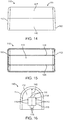
- the cage assembly 110 comprises an enclosure 111 having a general U-shape and side portions 112 and 113 which may have an opening 114 with a plurality of protrusions or nibs 115 configured to receive the post 107 of a positioning system 103.
- the enclosure 111 may be formed from plastic materials of suitable strength and durability such as, for example, poly-ester based plastics such as polyethylene terephthalate (PET) and other extruded or molded plastics.
- PET polyethylene terephthalate
- the strength of the plastic is required to not crush under pressure from the positioning system 103 such as under the weight of a limb of the patient 101.
- strength of the plastic is required to not tear from pressure from the use of the distractor assembly 104.
- the durability of the plastic functions to withstand conditions and factors in the operating room, medical procedure and sterilization therefore (i.e. high temperatures for proscribed periods of time).
- the enclosure 111 may be formed with side portions 112 and 113 and an arcuate side 140 having an outer surface 117 and an inner surface 118.
- the outer surface 117 of the arcuate side 140 may be formed generally smooth and in a general U-shape so as to secure the pad assembly 130 thereto such as, for example, using adhesives and the like.
- the inner surface 118 may be formed with ridges 119 and 120 to provide strength to the arcuate side 140 of the enclosure 111 so as to not crush under pressure from the positioning system 104 such as under the weight of a limb of the patient 101.
- the one or more ridges 119 and 120 are disposed along the longitudinal axis of the enclosure running along both the side portions 112, 113 and arcuate side 140 ( e.g. along the inner surface 118).
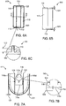
- the one or more ridges 119, 120 also are disposed adjacent the opening 114, i.e. on either side as illustrated in FIGS. 5 , 6A-6C and 7A .
- the design and placement of the ridges 119 and 120 functions (1) strengthen the area of the arcuate side 140 disposed under the limb of the patient 101 to increase load distribution and resist collapse; and (2) to resist tearing of the opening 114 by the post 107 when stressed by the pressure of the distractor assembly 104 pushing the assembly 100 against the limb of the patient 101 as occurs in the medical procedure 105 (e.g. to set and hold the limb in a surgical operation).
- the one or more ridges 119, 120 are configured to be molded with a predetermined height 122 and shape e.g . approximately at an 18 degree spread at the base with a radius of .03. In this manner, the ridges 119 and 120 are configured to reduce weight and cost by using less material for the enclosure 111.
- the side portions 112 and 113 are configured with a predetermined angle 121 may be formed angled ( e.g . approximately 2 degrees).
- the side portions 112, 113 also may have an opening 114 formed therein.
- the opening 114 has nibs 116 formed on an inner edge 115 in a predetermined dimension 123 and spaced apart a predetermined distance 124.
- the opening 114 is dimensioned to receive the post 107 of the positioning system 103.
- the nibs 116 are formed on inner edge 115 of the opening 114 and further may be designated edges 115a, 115b, 115c, and 115d as illustrated in FIG. 7A .
- the side portions 112, 113 are disposed at a predetermined angle 121 of approximately between 1 and 5 degrees measured from an apex of the u-shape of the arcuate side 140 to a lower edge of one or more of the side portions 112, 113.
- the edges 115a and 115c and the angle of the side portions 112 and 113 e.g. preferably 2 degree displacement angle from apex (top) to side edge (bottom) cooperate to form a spring lever suitable for locking the assembly to the support bar, e.g. of a surgical distraction system.
- the edges 115b and 115d also provide friction fit on post 107.
- the spring lever of the edges 115a and 115c uses spaces apart and displaces the nibs 116 on surface 115a and nibs 116 on surface 115c such that when stress is applied by the distractor assembly 104 these nibs 116 create a stronger hold on the support bar or post 107.
- the spring lever provides a broad distribution of pressure on the protector pad so as not to slip, rotate or roll according to an embodiment of the present invention.
- the nibs 116 are configured to be molded with a predetermined height 122 and shape into the side portions 112, 113.
- the nibs 116 are formed in a predetermined dimension 123 and spaced apart a predetermined distance 124.
- the predetermined dimension 123 of the nibs 116 functions to maintain the position of the pressure pad apparatus and system 100 on the support bar or post 107.
- the nibs 116 improve the friction with the post 107 when the distractor assembly 104 increases the load on the limb of the patient 101, which is an improvement over the prior art. For example, problems of slippage and not holding and maintaining the position on the post 107 occur in prior art systems, for example, when large limbs are operated on in the medical procedure 105.
Landscapes
- Health & Medical Sciences (AREA)
- Life Sciences & Earth Sciences (AREA)
- General Health & Medical Sciences (AREA)
- Veterinary Medicine (AREA)
- Engineering & Computer Science (AREA)
- Biomedical Technology (AREA)
- Public Health (AREA)
- Animal Behavior & Ethology (AREA)
- Orthopedic Medicine & Surgery (AREA)
- Heart & Thoracic Surgery (AREA)
- Vascular Medicine (AREA)
- Nursing (AREA)
- Chemical & Material Sciences (AREA)
- Dispersion Chemistry (AREA)
- Surgery (AREA)
- Orthopedics, Nursing, And Contraception (AREA)
- Nuclear Medicine, Radiotherapy & Molecular Imaging (AREA)
- Medical Informatics (AREA)
- Molecular Biology (AREA)
- Surgical Instruments (AREA)
Description
- This application claims the benefit of
U.S. Provisional Application No. 62/118,009 filed Feb. 19, 2016 - The present invention relates to reducing the tissue trauma that occurs when a physician distends or otherwise deforms a patient's tissues in a surgical Operation or for other medical procedures and, more particularly, to an improved positioning pad assembly and system for securing and holding a limb in a particular position and/or in conjunction with distraction of a joint, bone that advantageously reduces slippage and is particularly useful in the positioning of a larger, heavier body part.
- Conventional positioning and distraction systems are useful in positioning a body part (e.g. limb, knee, bone, joint, etc.) of a patient for robotic, laparoscopic and other medical procedures when a physician distends or otherwise deforms a patient's tissues in a surgical operation. For example, distraction may be used in medical procedures to separate two parts of a bone after the bone is transected. Also, distraction may be used in surgical procedures to provide distraction of joint surfaces without displacement and/or rupture of their binding ligaments. Consequently, these endoscopic, robotic, laparoscopic and other medical procedures use surgical distraction systems to separate bones, bony fragments or joint surfaces of a limb, e.g. when such extension is desired. An conventional positioning system is disclosed in
GB 1 376 386 - Conventional surgical positioning and distraction systems may use a foam pad and/or a cohesive wrap to protect a patient from pressure sores, abrasions and possible neurological impairment while securing foot into the boot. For example, sterile foam pads and wraps may be utilized with surgical distraction systems for reducing the pressure placed against the thigh in a medical procedure on a knee or ankle (e.g. pressure sores, abrasions and possible neurological impairment). In such medical procedures, a foam pad and/or wrap also must be sterilized and are typically single use.
- Conventional sterile foam pads have problems in maintaining position on a bracket and/or in a boot device as these may slip or shift when a distractor is used for flexion, extension, tilt, and rotation, e.g. when distracting the ankle or knee during arthroscopic surgery. Such problems in conventional wraps and foam pads are amplified when heavier, larger limbs of a heavier and/or larger patient are being positioned for surgery as well as during surgery. One solution has been to increase the pressure on the pad using distraction; however, pads slide off of the support post, fail and any such increased pressure can be harmful to the circulatory system, tissues, bones, and patient health. As a result, there is a need for an improved positioning pad assembly and system for securing and holding a limb in a particular position and/or in conjunction with distraction of a joint, bone or in the positioning of a body part for a surgical Operation to overcome these and other harmful problems to the circulatory system, tissues, bones, and patient health that are present in conventional surgical positioning and distraction systems.
- The present invention solves these problems with a pad assembly and system that has improved holding, resists slippage, and results in less harm to the patient's circulatory system, tissues, and/or bones, thereby improving a patient's health. The improved pad assembly and system according to the present invention maintains its hold and position on a support bar or distractor bar bracket, thereby allowing reduced applied pressure of the distractor against the thigh as compared to conventional surgical positioning and distraction systems. Moreover, the present invention reduces repositioning because its design reduces support bar sliding and slippage especially when distracting heavier, larger limbs of a heavier and/or larger patient before and during a surgical procedure.
- It is an object of the present invention to provide a pad assembly and system of positioning and holding a foam pad assembly that reduces and/or eliminates harmful problems to the circulatory system, tissues, bones, patient health, and otherwise is gentler for the patient.
- An object of the present invention is to provide a pad assembly and system for securing and holding a limb in a particular position and/or in conjunction with the positioning of a body part, distraction of a joint, and distraction of bone in a medical procedure.
- Another object of the present invention is to provide a protector pad assembly and system for reducing harm to the circulatory system, tissues, bones, and improving patient health by distributing pressure over a large area of the distal femur reducing the direct application of pressure an tissues, vessels and the popliteal nerve.
- Yet another object of the present invention is to provide a protector pad assembly and system that maintains its position so as not to shift, slide or roll into the popliteal area. It is an object of the present invention to provide these advantages for a pad assembly that overcomes the shifting into the popliteal area and related problems that are amplified when larger, heavier limbs are being positioned for surgery and throughout a surgical procedure.
- Still yet another object of the present invention is to provide a protector pad assembly and system with advantages of a sterilized product that may be produced and sold as a pressure protector pad set or kit for use with a positioning and/or distractor system such as, for example, the De Mayo Universal Distractor as disclosed in
U.S. Patent No. 8,048,082 B1 . - It is an object of the present invention to provide an apparatus and system of positioning and holding a sterile pad assembly and system with design features for locking to a support bar so as to hold and maintain its position thereby reducing pressure needed to be placed against the thigh in a typical procedure without repositioning.
- Non-limiting and non-exhaustive embodiments of the present invention are described with reference to the following drawings. In the drawings, like reference numerals refer to like parts throughout the various figures unless otherwise specified.
- For a better understanding of the present invention, reference will be made to the following Description of the Embodiments, which is to be read in association with the accompanying drawings, which are incorporated in and constitute a part of this specification, show certain aspects of the subject matter disclosed herein and, together with the description, help explain some of the principles associated with the disclosed implementations, wherein:
-
FIG. 1 illustrates is a perspective view of the apparatus system in accordance with an embodiment of the present invention; -
FIG. 2 illustrates is a side view of the apparatus and system; -
FIG. 3 illustrates is an end view of the apparatus and system; -
FIG. 4 illustrates is a top view of the apparatus and system; -
FIG. 5 illustrates is a bottom view of the apparatus and system; -
FIG. 6A illustrates a bottom view,FIG. 6B illustrates a side view, andFIG. 6C illustrates a sectional view of the apparatus and system along circle line C-C in accordance with an embodiment of the present invention; -
FIG. 7A illustrates a side view of the side portion and opening taken along lines A-A ofFIG. 6A; and 7B illustrate is sectional view along circle line B-B ofFIG. 7A of the apparatus and system in accordance with an embodiment of the present invention; -
FIG. 8 illustrates a perspective view of the foam protector pad; -
FIG. 9 illustrates an end view of the foam protector pad; -
FIG. 10 illustrates a top and or bottom view of the foam protector pad; -
FIG. 11 illustrates an end view of the foam protector pad bend to shape in accordance with an embodiment of the present invention; -
FIG. 12 illustrates is a perspective view of the foam protector pad bend to shape; -
FIG. 13 illustrates is a side view of the foam protector pad bend to shape; -
FIG. 14 illustrates is a side view of support of the pad assembly and system in accordance with an embodiment of the present invention -
FIG. 15 illustrates is a bottom view of support of the pad assembly and system -
FIG. 16 illustrates is an end view of the support of the pad assembly and system; -
FIG. 17 illustrates is a side perspective view of the support the pad assembly and system in a surgical Operation with a distractor; and -
FIG. 18 illustrates is an anatomical view of the posterior of a human limb. - Non-limiting embodiments of the present invention will be described below with reference to the accompanying drawings, wherein like reference numerals represent like elements throughout. While the invention has been described in detail with respect to the preferred embodiments thereof, it will be appreciated that upon reading and understanding of the foregoing, certain variations to the preferred embodiments will become apparent.
- The terms "a" or "an", as used herein, are defined as one or as more than one. The term "plurality", as used herein, is defined as two or as more than two. The term "another", as used herein, is defined as at least a second or more. The terms "including" and/or "having", as used herein, are defined as comprising (i.e., open language). The term "coupled", as used herein, is defined as connected, although not necessarily directly, and not necessarily mechanically.
- Reference throughout this document to "some embodiments", "one embodiment", "certain embodiments", and "an embodiment" or similar terms means that a particular feature, structure, or characteristic described in connection with the embodiment is included in at least one embodiment of the present invention. Thus, the appearances of such phrases or in various places throughout this specification are not necessarily all referring to the same embodiment. Furthermore, the particular features, structures, or characteristics may be combined in any suitable manner in one or more embodiments without limitation.
- The term "or" as used herein is to be interpreted as an inclusive or meaning any one or any combination. Therefore, "A, B or C" means any of the following: "A; B; C; A and B; A and C; B and C; A, B and C". An exception to this definition will occur only when a combination of elements, functions, steps or acts are in some way inherently mutually exclusive.
- The drawings featured in the figures are provided for the purposes of illustrating some embodiments of the present invention, and are not to be considered as limitation thereto. Term "means" preceding a present participle of an Operation indicates a desired function for which there is one or more embodiments, i.e., one or more methods, devices, or apparatuses for achieving the desired function and that one skilled in the art could select from these or their equivalent in view of the disclosure herein and use of the term "means" is not intended to be limiting.
- As used herein the term "popliteal area" refers to the posterior area of the human leg around the knee joint and its tissues, bones circulatory and nerve structures. The area is visually identifiable as a shallow depression located at the back of the knee joint that includes the popliteal artery, popliteal nerve, tibial artery, tibial nerve and other tissues.
- As used herein the term "popliteal artery" refers to an artery that is a deeply placed continuation of the femoral artery after it passes through the adductor hiatus, or opening in the distal portion of the adductor magnus muscle. The popliteal artery courses through the popliteal fossa and ends at the lower border of the popliteus muscle, where it branches into the anterior and posterior tibial arteries.
- As used herein the term "popliteal nerve" refers to a common fibular nerve (common peroneal nerve; external popliteal nerve; peroneal nerve; lateral popliteal nerve), about one-half the size of the tibial nerve, is derived from the dorsal branches of the fourth and fifth lumbar and the first and second sacral nerves. The popliteal nerve descends obliquely along the lateral side of the popliteal fossa to the head of the fibula, close to the medial margin of the biceps femoris muscle and the common peroneal nerve winds round the head of the fibula as is illustrated in
FIG. 18 . - As used herein the term "tibial artery" refers to the anterior tibial artery of the leg functioning to carry blood to the anterior compartment of the leg and dorsal surface of the foot, from the popliteal artery, which also is accompanied the anterior tibial vein, along its course.
- As used herein the term "tibial nerve" refers to the tibial nerve that is a branch of the sciatic nerve. The tibial nerve passes through the popliteal fossa to pass below the arch of soleus.
- As is illustrated in
FIGS. 1-18 , the pressure pad apparatus andsystem 100, such as shown inFIG. 1 , is useful to sufficiently optimize secure, hold, and maintain the limb of a patient 101 (e.g. leg, knee, ankle, etc.) in a desired position against displacement and pressure forces during a medical procedure to the pressure pad apparatus andsystem 100 disposed on a support bar of a surgical distractor unit. As shown inFIG. 17 , the limb of thepatient 101 is set in a desired position on a support or operating (OR) table 102 configured with apositioning system 103, adistractor assembly 104, or both (103 and 104) in amedical procedure 105. Accordingly, the present invention is described in an arthroscopic surgerymedical procedure 105 in an embodiment of arthroscopy and/or arthroscopic surgery for the repair of the joint (i.e. on the knee as shown inFIGS. 17 and 18 ) using the pressure pad apparatus andsystem 100, illustrated inFIGS. 1-16 . As shown inFIGS. 17 and 18 , the pressure pad apparatus and system is configured to work with apositioner 103 and/ordistractor 104 such as the De Mayo Universal Distractor® for the knee and ankle surgical procedures involved in the finite joint distraction of the surgical site, which is described inU.S. Patent No. 8,048,082 B1 . Although it should appreciated that the principals of the present invention may be used in other arthroscopic surgery medical procedures commonly used for ankle, hip, wrist, elbow, shoulder problems, whereby the improvements and advantages of the pressure pad apparatus andsystem 100 may further apply to disadvantages in the prior art for the reduction of injury to the joint, tissues, bones, circulatory and nerve structures. - Referring to
FIG. 17 , in predetermined arthroscopic surgery on the kneemedical procedure 105, the positioning pad andsystem 100 is attached to the limb support bar of apositioning system 103 that secures and holds the limb of the patient 101 (i.e. upper and lower leg and foot) to prevent movement on the OR table 102, which movements could be disruptive to amedical procedure 105 being performed on thepatient 101. Apressure pad apparatus 100 may be utilized with thepositioning system 103 so as to hyper-extend the joint (i.e. knee or ankle in this configuration) for the medical procedure as illustrated inFIG. 17 . Simply, a limb of thepatient 101 is positioned on thepressure pad apparatus 100 that is disposed on the limb support bar or post 107 of thepositioning system 103. The pressure pad apparatus is also connected to thedistractor assembly 104 used to hyper-extend the knee for the medical procedure as illustrated inFIG. 17 . - According to the knee arthroscopic surgery embodiment of the present invention, the pressure pad apparatus and
system 100 has advantages in the reduction of injury to the joint, tissues and arterial structures of thepopliteal area 106 around the knee joint and its tissues, bones, circulatory and nerve structures when distracting a knee for a surgical Operation as shown inFIG. 17 . In this embodiment, thepopliteal area 106 of thepatient 101 is protected from injury by the cooperation of thepad assembly 130 with thecage assembly 110. The spring lever of the pad assembly, system andkit 100 is configured to provide a sterile protector pad with a broad distribution of pressure thereby resisting crushing, tearing at theopening 114, or otherwise slipping, sliding, rotating and/or rolling off of the support bar according to an embodiment of the present invention. - As is illustrated in
FIGS. 1-18 , the pressure pad apparatus andsystem 100 comprises of acage assembly 110 and apad assembly 130. As is illustrated inFIGS. 8-13 , thepad assembly 130 of the pressure pad apparatus andsystem 100 may be configured as a generally rectangular pad. Thepad assembly 130 has atop surface 131,bottom surface 132, andsides top surface 131 is disposed adjacent the patient's 101 limb near the joint to be extended such as, for example, in thepopliteal area 106. Thebottom surface 132 thepad assembly 130 is affixed by adhesive to theouter surface 117 on theenclosure 111 ofcage assembly 110. Thepad assembly 130 may be formed from suitable foam and cell structure materials that can be sterilized such as, for example, polyurethane-based foam. The enclosure orcage assembly 110 is configured with one or more ridges to sufficiently optimize a material strength to the arcuate side of the enclosure so as to not crush under pressure from the surgical distractor unit and/or the weight of the patient's limb of the patient when thesterile cage assembly 110 andpad assembly 130 support a limb of a patient as the support bar of the distractor unit positions thepad assembly 130 in abutment with a popliteal area of a patient's knee joint during a medical procedure. - As is illustrated in
FIGS. 14-16 thecage assembly 110 comprises anenclosure 111 having a general U-shape andside portions opening 114 with a plurality of protrusions ornibs 115 configured to receive thepost 107 of apositioning system 103. Theenclosure 111 may be formed from plastic materials of suitable strength and durability such as, for example, poly-ester based plastics such as polyethylene terephthalate (PET) and other extruded or molded plastics. The strength of the plastic is required to not crush under pressure from thepositioning system 103 such as under the weight of a limb of thepatient 101. Moreover, strength of the plastic is required to not tear from pressure from the use of thedistractor assembly 104. The durability of the plastic functions to withstand conditions and factors in the operating room, medical procedure and sterilization therefore (i.e. high temperatures for proscribed periods of time). - As is illustrated in
FIGS. 6A-6C, 7A-7B ,14-16 , theenclosure 111 may be formed withside portions arcuate side 140 having anouter surface 117 and aninner surface 118. Theouter surface 117 of thearcuate side 140 may be formed generally smooth and in a general U-shape so as to secure thepad assembly 130 thereto such as, for example, using adhesives and the like. Theinner surface 118 may be formed withridges arcuate side 140 of theenclosure 111 so as to not crush under pressure from thepositioning system 104 such as under the weight of a limb of thepatient 101. The one ormore ridges side portions more ridges opening 114, i.e. on either side as illustrated inFIGS. 5 ,6A-6C and 7A . The design and placement of theridges arcuate side 140 disposed under the limb of thepatient 101 to increase load distribution and resist collapse; and (2) to resist tearing of theopening 114 by thepost 107 when stressed by the pressure of thedistractor assembly 104 pushing theassembly 100 against the limb of thepatient 101 as occurs in the medical procedure 105 (e.g. to set and hold the limb in a surgical operation). As shown inFIG. 6C , the one ormore ridges predetermined height 122 and shape e.g. approximately at an 18 degree spread at the base with a radius of .03. In this manner, theridges enclosure 111. - Referring to
FIGS. 2 and6B theside portions predetermined angle 121 may be formed angled (e.g. approximately 2 degrees). As illustrated inFIGS. 7A and 7B , theside portions opening 114 formed therein. As illustrated inFIGS. 6A-6B, 7A-7C , theopening 114 hasnibs 116 formed on aninner edge 115 in apredetermined dimension 123 and spaced apart apredetermined distance 124. Theopening 114 is dimensioned to receive thepost 107 of thepositioning system 103. Thenibs 116 are formed oninner edge 115 of theopening 114 and further may be designatededges FIG. 7A . - The
side portions predetermined angle 121 of approximately between 1 and 5 degrees measured from an apex of the u-shape of thearcuate side 140 to a lower edge of one or more of theside portions edges side portions 112 and 113 (e.g. preferably 2 degree displacement angle from apex (top) to side edge (bottom)) cooperate to form a spring lever suitable for locking the assembly to the support bar, e.g. of a surgical distraction system. Theedges 115b and 115d also provide friction fit onpost 107. The spring lever of theedges nibs 116 onsurface 115a andnibs 116 onsurface 115c such that when stress is applied by thedistractor assembly 104 thesenibs 116 create a stronger hold on the support bar or post 107. The spring lever provides a broad distribution of pressure on the protector pad so as not to slip, rotate or roll according to an embodiment of the present invention. - As illustrated in
FIGS. 7A and 7B , thenibs 116 are configured to be molded with apredetermined height 122 and shape into theside portions FIG. 7B , thenibs 116 are formed in apredetermined dimension 123 and spaced apart apredetermined distance 124. Thepredetermined dimension 123 of thenibs 116 functions to maintain the position of the pressure pad apparatus andsystem 100 on the support bar or post 107. Thenibs 116 improve the friction with thepost 107 when thedistractor assembly 104 increases the load on the limb of thepatient 101, which is an improvement over the prior art. For example, problems of slippage and not holding and maintaining the position on thepost 107 occur in prior art systems, for example, when large limbs are operated on in themedical procedure 105. - While certain configurations of structures have been illustrated for the purposes of presenting the basic structures of the present invention, one of ordinary skill in the art will appreciate that other variations are possible. Additional advantages and modifications will readily occur to those skilled in the art.
Claims (14)
- An assembly for supporting a limb of a patient during a medical procedure (105) configured to be received by a support bar (107) of a surgical distractor unit (104) for separating anatomical portions of the patient's limb (101) during the medical procedure (105), said assembly comprising:an enclosure (111) configured with side portions (112, 113), an opening (114) formed in each of said side portions (112, 113) adapted to receive slidably the support bar (107), and an arcuate side (140) connected to said side portions (112, 113) formed in a generally u-shape, said enclosure (111) is configured with one or more ridges (119, 120) adjacent the openings (114) to optimize a spring lever, formed by the edges (115a, 115c) of the opening (114) and an angle (121) measured from an apex of the u-shape of the arcuate side (140) to a lower edge of the side portions (112, 113), and under pressure from the surgical distractor unit (104); anda pad (130) disposed on said arcuate side (140) of said enclosure (111).
- The assembly of claim 1, wherein said enclosure (111) and pad (130) are suited to be sterilized for supporting a limb of a patient (101) during a medical procedure (105).
- The assembly of claim 1, wherein said enclosure (111) is configured with one or more ridges (119, 120) on said arcuate side (140) of said enclosure (111) to reduce weight and strengthen the material strength under pressure from the surgical distractor unit (104) and/or the weight of the patient's limb of the patient (101).
- The assembly of claim 3, wherein said enclosure (111) is configured with said ridges (119, 120) disposed along a longitudinal axis of said enclosure (111) between said side portions (112, 113) and said arcuate side (140).
- The assembly of claim 1, wherein said side portions (112, 113) are disposed at said predetermined angle (121) of approximately between 1 and 5 degrees from an apex of the u-shape of said arcuate side (140) to a lower edge of said side portions (112, 113).
- The assembly of claim 1, wherein said pad (130) is affixed to an outer surface (117) of said enclosure (111) thereto using adhesives.
- The assembly of claim 1, wherein said pad (130) is formed from suitable foam and cell structure materials that can be sterilized including polyurethane-based foam.
- The assembly of claim 1, in combination with a system for supporting a limb of a patient (101) during a medical procedure (105), said system comprising:a surgical distractor unit (104) for separating a pair of adjacent bones within a patient's joint during surgery without insertion within said patient (101) comprising an outer cylinder arrangedbetween a support bar (107) at one end to be positioned adjacent the patient's limb and a base supportbar at an opposite end thereof for attaching for said surgical distractor unit (104) to a support base, said surgical distractor unit (104) configured to move said support bar (107) relative to said base support bar to control a separation distance between said patient's bones, joints and/or tissues before, during and after surgery thereon;the cage assembly (110) configured to be received by said support bar (107) so as to abut a patient's joint, said cage assembly (110) comprising:
said openings (114) configured with one or more nibs (116) disposed on an edge (115a, 115c) of said openings (114), said nibs (116) configured to optimize holding of said enclosure (111) on said support bar (107) in a desired position against pressure forces during a medical procedure (105). - The system of claim 8, wherein said support bar (107) positions said pad (130) assembly in abutment with a popliteal area (106) of a patient's knee joint.
- The system of claim 8, wherein said pad (130) affixed to a gel base portion from the group of a staple, stitch, glue, adhesive, or other fastener.
- The system of claim 8, wherein said base support bar includes means for attachment to an operating table (107) side rail or a patient limb support device.
- The system of claim 8, wherein said side portions (112, 113) are disposed at a predetermined angle of approximately between 1 and 5 degrees from an apex of the u-shape of said arcuate side (140) to a lower edge of said side portions (112, 113).
- The system of Claim 8, wherein said sterile pad is formed from suitable foam and cell structure materials that can be sterilized including polyurethane-based foam.
- The assembly of claim 8, wherein said pad (130) for supporting a limb of a procedure (105), is adapted to be in abutment with a popliteal area (106) of a patient's knee joint in a patient anchoring system comprising:
said cage assembly (110) configured to be received by a support bar (107) so as to abut the patient's Joint.
Applications Claiming Priority (2)
| Application Number | Priority Date | Filing Date | Title |
|---|---|---|---|
| US201562118009P | 2015-02-19 | 2015-02-19 | |
| US15/048,577 US20170049654A1 (en) | 2015-02-19 | 2016-02-19 | Assembly and system for distractor and/or positioner |
Publications (2)
| Publication Number | Publication Date |
|---|---|
| EP3207913A1 EP3207913A1 (en) | 2017-08-23 |
| EP3207913B1 true EP3207913B1 (en) | 2020-01-08 |
Family
ID=58156907
Family Applications (1)
| Application Number | Title | Priority Date | Filing Date |
|---|---|---|---|
| EP17155968.5A Active EP3207913B1 (en) | 2015-02-19 | 2017-02-14 | Assembly and system for distractor and/or positioner |
Country Status (2)
| Country | Link |
|---|---|
| US (1) | US20170049654A1 (en) |
| EP (1) | EP3207913B1 (en) |
Families Citing this family (2)
| Publication number | Priority date | Publication date | Assignee | Title |
|---|---|---|---|---|
| US10842653B2 (en) | 2007-09-19 | 2020-11-24 | Ability Dynamics, Llc | Vacuum system for a prosthetic foot |
| US11389200B1 (en) | 2021-01-29 | 2022-07-19 | Globus Medical, Inc. | Systems and methods for leg stabilization during knee arthroplasty surgery |
Family Cites Families (3)
| Publication number | Priority date | Publication date | Assignee | Title |
|---|---|---|---|---|
| DE2235444C3 (en) * | 1972-07-20 | 1975-11-20 | Hinrichs Gmbh, 2054 Geesthacht | Device for performing operations on distracted knee joints |
| US5056535A (en) * | 1990-01-22 | 1991-10-15 | Leonard Medical | Varus and valgus leg manipulator |
| US8048082B1 (en) | 2007-12-11 | 2011-11-01 | Innovative Medical Product Inc. | Non-invasive femoral distractor for use in knee surgery |
-
2016
- 2016-02-19 US US15/048,577 patent/US20170049654A1/en not_active Abandoned
-
2017
- 2017-02-14 EP EP17155968.5A patent/EP3207913B1/en active Active
Non-Patent Citations (1)
| Title |
|---|
| None * |
Also Published As
| Publication number | Publication date |
|---|---|
| US20170049654A1 (en) | 2017-02-23 |
| EP3207913A1 (en) | 2017-08-23 |
Similar Documents
| Publication | Publication Date | Title |
|---|---|---|
| US10105274B2 (en) | Adjustable surgical support system | |
| US4886258A (en) | Well leg operative support | |
| EP2612625B1 (en) | Adjustable multi-component hip orthosis | |
| US6553995B1 (en) | Kit for support and stabilization of surgical patient extremities | |
| CN105615966A (en) | Method and apparatus for force redistributon in articular joints | |
| JP2013508078A (en) | Mechanical energy absorbing assembly implantable outside a joint having a tension member and method of implantation | |
| US7458933B2 (en) | Method for knee-joint surgery | |
| JP2013523319A (en) | Thigh base and tibial base | |
| Xing et al. | Comparison of minimally invasive arthrolysis vs. conventional arthrolysis for post-traumatic knee stiffness | |
| Mannava et al. | Basic hip arthroscopy: Supine patient positioning and dynamic fluoroscopic evaluation | |
| EP2512353B1 (en) | Dorsal forearm plate | |
| US12440200B2 (en) | Stabilizing retractor system | |
| JP2005532890A (en) | Method and apparatus for replacing a knee joint | |
| EP3207913A1 (en) | Assembly and system for distractor and/or positioner | |
| US7195593B1 (en) | Ligament retractor assembly | |
| US20170296159A1 (en) | Surgical retraction device | |
| Perry et al. | The pink pad: A method of post-free distraction during hip arthroscopy | |
| Misani et al. | Release of hand burn contracture: comparing the ALT perforator flap with the gracilis free flap with split skin graft | |
| Coventry | The surgical technique of total hip arthroplasty, modified from Charnley, as done at the Mayo Clinic | |
| BRPI0706495A2 (en) | pedicle plate and screw system and its applications | |
| Vallières | The costovertebral angle | |
| Hussain et al. | Vascular injury involving proximal medial-to-lateral oblique locking screw insertion in tibial intramedullary nailing | |
| US20260020969A1 (en) | Wearable orthopedic traction device for relieving shoulder pain | |
| US20180085275A1 (en) | Method and Apparatus for Variable Knee Flexion Support | |
| Işik et al. | Repair of thumb abduction contracture by microsurgical transfer of partial toe |
Legal Events
| Date | Code | Title | Description |
|---|---|---|---|
| PUAI | Public reference made under article 153(3) epc to a published international application that has entered the european phase |
Free format text: ORIGINAL CODE: 0009012 |
|
| STAA | Information on the status of an ep patent application or granted ep patent |
Free format text: STATUS: THE APPLICATION HAS BEEN PUBLISHED |
|
| AK | Designated contracting states |
Kind code of ref document: A1 Designated state(s): AL AT BE BG CH CY CZ DE DK EE ES FI FR GB GR HR HU IE IS IT LI LT LU LV MC MK MT NL NO PL PT RO RS SE SI SK SM TR |
|
| AX | Request for extension of the european patent |
Extension state: BA ME |
|
| STAA | Information on the status of an ep patent application or granted ep patent |
Free format text: STATUS: REQUEST FOR EXAMINATION WAS MADE |
|
| 17P | Request for examination filed |
Effective date: 20171201 |
|
| RBV | Designated contracting states (corrected) |
Designated state(s): AL AT BE BG CH CY CZ DE DK EE ES FI FR GB GR HR HU IE IS IT LI LT LU LV MC MK MT NL NO PL PT RO RS SE SI SK SM TR |
|
| STAA | Information on the status of an ep patent application or granted ep patent |
Free format text: STATUS: EXAMINATION IS IN PROGRESS |
|
| 17Q | First examination report despatched |
Effective date: 20180703 |
|
| RIN1 | Information on inventor provided before grant (corrected) |
Inventor name: DE MAYO, EDWARD Inventor name: BLACKWELL, TIM Inventor name: KOVACS, TAMAS |
|
| GRAP | Despatch of communication of intention to grant a patent |
Free format text: ORIGINAL CODE: EPIDOSNIGR1 |
|
| STAA | Information on the status of an ep patent application or granted ep patent |
Free format text: STATUS: GRANT OF PATENT IS INTENDED |
|
| RIC1 | Information provided on ipc code assigned before grant |
Ipc: A61F 5/37 20060101ALI20190626BHEP Ipc: A61G 13/00 20060101ALI20190626BHEP Ipc: A61G 13/12 20060101AFI20190626BHEP Ipc: A61G 13/10 20060101ALN20190626BHEP |
|
| RIC1 | Information provided on ipc code assigned before grant |
Ipc: A61G 13/12 20060101AFI20190717BHEP Ipc: A61F 5/37 20060101ALI20190717BHEP Ipc: A61G 13/00 20060101ALI20190717BHEP Ipc: A61G 13/10 20060101ALN20190717BHEP |
|
| INTG | Intention to grant announced |
Effective date: 20190731 |
|
| GRAS | Grant fee paid |
Free format text: ORIGINAL CODE: EPIDOSNIGR3 |
|
| GRAA | (expected) grant |
Free format text: ORIGINAL CODE: 0009210 |
|
| STAA | Information on the status of an ep patent application or granted ep patent |
Free format text: STATUS: THE PATENT HAS BEEN GRANTED |
|
| AK | Designated contracting states |
Kind code of ref document: B1 Designated state(s): AL AT BE BG CH CY CZ DE DK EE ES FI FR GB GR HR HU IE IS IT LI LT LU LV MC MK MT NL NO PL PT RO RS SE SI SK SM TR |
|
| REG | Reference to a national code |
Ref country code: GB Ref legal event code: FG4D |
|
| REG | Reference to a national code |
Ref country code: CH Ref legal event code: EP |
|
| REG | Reference to a national code |
Ref country code: DE Ref legal event code: R096 Ref document number: 602017010522 Country of ref document: DE |
|
| REG | Reference to a national code |
Ref country code: IE Ref legal event code: FG4D |
|
| REG | Reference to a national code |
Ref country code: AT Ref legal event code: REF Ref document number: 1221781 Country of ref document: AT Kind code of ref document: T Effective date: 20200215 |
|
| REG | Reference to a national code |
Ref country code: NL Ref legal event code: MP Effective date: 20200108 |
|
| REG | Reference to a national code |
Ref country code: LT Ref legal event code: MG4D |
|
| PG25 | Lapsed in a contracting state [announced via postgrant information from national office to epo] |
Ref country code: PT Free format text: LAPSE BECAUSE OF FAILURE TO SUBMIT A TRANSLATION OF THE DESCRIPTION OR TO PAY THE FEE WITHIN THE PRESCRIBED TIME-LIMIT Effective date: 20200531 Ref country code: RS Free format text: LAPSE BECAUSE OF FAILURE TO SUBMIT A TRANSLATION OF THE DESCRIPTION OR TO PAY THE FEE WITHIN THE PRESCRIBED TIME-LIMIT Effective date: 20200108 Ref country code: NO Free format text: LAPSE BECAUSE OF FAILURE TO SUBMIT A TRANSLATION OF THE DESCRIPTION OR TO PAY THE FEE WITHIN THE PRESCRIBED TIME-LIMIT Effective date: 20200408 Ref country code: FI Free format text: LAPSE BECAUSE OF FAILURE TO SUBMIT A TRANSLATION OF THE DESCRIPTION OR TO PAY THE FEE WITHIN THE PRESCRIBED TIME-LIMIT Effective date: 20200108 Ref country code: NL Free format text: LAPSE BECAUSE OF FAILURE TO SUBMIT A TRANSLATION OF THE DESCRIPTION OR TO PAY THE FEE WITHIN THE PRESCRIBED TIME-LIMIT Effective date: 20200108 Ref country code: LT Free format text: LAPSE BECAUSE OF FAILURE TO SUBMIT A TRANSLATION OF THE DESCRIPTION OR TO PAY THE FEE WITHIN THE PRESCRIBED TIME-LIMIT Effective date: 20200108 |
|
| PG25 | Lapsed in a contracting state [announced via postgrant information from national office to epo] |
Ref country code: SE Free format text: LAPSE BECAUSE OF FAILURE TO SUBMIT A TRANSLATION OF THE DESCRIPTION OR TO PAY THE FEE WITHIN THE PRESCRIBED TIME-LIMIT Effective date: 20200108 Ref country code: LV Free format text: LAPSE BECAUSE OF FAILURE TO SUBMIT A TRANSLATION OF THE DESCRIPTION OR TO PAY THE FEE WITHIN THE PRESCRIBED TIME-LIMIT Effective date: 20200108 Ref country code: BG Free format text: LAPSE BECAUSE OF FAILURE TO SUBMIT A TRANSLATION OF THE DESCRIPTION OR TO PAY THE FEE WITHIN THE PRESCRIBED TIME-LIMIT Effective date: 20200408 Ref country code: IS Free format text: LAPSE BECAUSE OF FAILURE TO SUBMIT A TRANSLATION OF THE DESCRIPTION OR TO PAY THE FEE WITHIN THE PRESCRIBED TIME-LIMIT Effective date: 20200508 Ref country code: GR Free format text: LAPSE BECAUSE OF FAILURE TO SUBMIT A TRANSLATION OF THE DESCRIPTION OR TO PAY THE FEE WITHIN THE PRESCRIBED TIME-LIMIT Effective date: 20200409 Ref country code: HR Free format text: LAPSE BECAUSE OF FAILURE TO SUBMIT A TRANSLATION OF THE DESCRIPTION OR TO PAY THE FEE WITHIN THE PRESCRIBED TIME-LIMIT Effective date: 20200108 |
|
| REG | Reference to a national code |
Ref country code: DE Ref legal event code: R119 Ref document number: 602017010522 Country of ref document: DE |
|
| REG | Reference to a national code |
Ref country code: CH Ref legal event code: PL |
|
| REG | Reference to a national code |
Ref country code: BE Ref legal event code: MM Effective date: 20200229 |
|
| PG25 | Lapsed in a contracting state [announced via postgrant information from national office to epo] |
Ref country code: DK Free format text: LAPSE BECAUSE OF FAILURE TO SUBMIT A TRANSLATION OF THE DESCRIPTION OR TO PAY THE FEE WITHIN THE PRESCRIBED TIME-LIMIT Effective date: 20200108 Ref country code: SK Free format text: LAPSE BECAUSE OF FAILURE TO SUBMIT A TRANSLATION OF THE DESCRIPTION OR TO PAY THE FEE WITHIN THE PRESCRIBED TIME-LIMIT Effective date: 20200108 Ref country code: ES Free format text: LAPSE BECAUSE OF FAILURE TO SUBMIT A TRANSLATION OF THE DESCRIPTION OR TO PAY THE FEE WITHIN THE PRESCRIBED TIME-LIMIT Effective date: 20200108 Ref country code: MC Free format text: LAPSE BECAUSE OF FAILURE TO SUBMIT A TRANSLATION OF THE DESCRIPTION OR TO PAY THE FEE WITHIN THE PRESCRIBED TIME-LIMIT Effective date: 20200108 Ref country code: RO Free format text: LAPSE BECAUSE OF FAILURE TO SUBMIT A TRANSLATION OF THE DESCRIPTION OR TO PAY THE FEE WITHIN THE PRESCRIBED TIME-LIMIT Effective date: 20200108 Ref country code: CZ Free format text: LAPSE BECAUSE OF FAILURE TO SUBMIT A TRANSLATION OF THE DESCRIPTION OR TO PAY THE FEE WITHIN THE PRESCRIBED TIME-LIMIT Effective date: 20200108 Ref country code: LU Free format text: LAPSE BECAUSE OF NON-PAYMENT OF DUE FEES Effective date: 20200214 Ref country code: EE Free format text: LAPSE BECAUSE OF FAILURE TO SUBMIT A TRANSLATION OF THE DESCRIPTION OR TO PAY THE FEE WITHIN THE PRESCRIBED TIME-LIMIT Effective date: 20200108 Ref country code: SM Free format text: LAPSE BECAUSE OF FAILURE TO SUBMIT A TRANSLATION OF THE DESCRIPTION OR TO PAY THE FEE WITHIN THE PRESCRIBED TIME-LIMIT Effective date: 20200108 |
|
| PLBE | No opposition filed within time limit |
Free format text: ORIGINAL CODE: 0009261 |
|
| STAA | Information on the status of an ep patent application or granted ep patent |
Free format text: STATUS: NO OPPOSITION FILED WITHIN TIME LIMIT |
|
| REG | Reference to a national code |
Ref country code: AT Ref legal event code: MK05 Ref document number: 1221781 Country of ref document: AT Kind code of ref document: T Effective date: 20200108 |
|
| PG25 | Lapsed in a contracting state [announced via postgrant information from national office to epo] |
Ref country code: CH Free format text: LAPSE BECAUSE OF NON-PAYMENT OF DUE FEES Effective date: 20200229 Ref country code: LI Free format text: LAPSE BECAUSE OF NON-PAYMENT OF DUE FEES Effective date: 20200229 |
|
| 26N | No opposition filed |
Effective date: 20201009 |
|
| PG25 | Lapsed in a contracting state [announced via postgrant information from national office to epo] |
Ref country code: IE Free format text: LAPSE BECAUSE OF NON-PAYMENT OF DUE FEES Effective date: 20200214 Ref country code: FR Free format text: LAPSE BECAUSE OF NON-PAYMENT OF DUE FEES Effective date: 20200308 Ref country code: DE Free format text: LAPSE BECAUSE OF NON-PAYMENT OF DUE FEES Effective date: 20200901 Ref country code: IT Free format text: LAPSE BECAUSE OF FAILURE TO SUBMIT A TRANSLATION OF THE DESCRIPTION OR TO PAY THE FEE WITHIN THE PRESCRIBED TIME-LIMIT Effective date: 20200108 Ref country code: AT Free format text: LAPSE BECAUSE OF FAILURE TO SUBMIT A TRANSLATION OF THE DESCRIPTION OR TO PAY THE FEE WITHIN THE PRESCRIBED TIME-LIMIT Effective date: 20200108 |
|
| PG25 | Lapsed in a contracting state [announced via postgrant information from national office to epo] |
Ref country code: SI Free format text: LAPSE BECAUSE OF FAILURE TO SUBMIT A TRANSLATION OF THE DESCRIPTION OR TO PAY THE FEE WITHIN THE PRESCRIBED TIME-LIMIT Effective date: 20200108 Ref country code: PL Free format text: LAPSE BECAUSE OF FAILURE TO SUBMIT A TRANSLATION OF THE DESCRIPTION OR TO PAY THE FEE WITHIN THE PRESCRIBED TIME-LIMIT Effective date: 20200108 Ref country code: BE Free format text: LAPSE BECAUSE OF NON-PAYMENT OF DUE FEES Effective date: 20200229 |
|
| GBPC | Gb: european patent ceased through non-payment of renewal fee |
Effective date: 20210214 |
|
| PG25 | Lapsed in a contracting state [announced via postgrant information from national office to epo] |
Ref country code: GB Free format text: LAPSE BECAUSE OF NON-PAYMENT OF DUE FEES Effective date: 20210214 |
|
| PG25 | Lapsed in a contracting state [announced via postgrant information from national office to epo] |
Ref country code: TR Free format text: LAPSE BECAUSE OF FAILURE TO SUBMIT A TRANSLATION OF THE DESCRIPTION OR TO PAY THE FEE WITHIN THE PRESCRIBED TIME-LIMIT Effective date: 20200108 Ref country code: MT Free format text: LAPSE BECAUSE OF FAILURE TO SUBMIT A TRANSLATION OF THE DESCRIPTION OR TO PAY THE FEE WITHIN THE PRESCRIBED TIME-LIMIT Effective date: 20200108 Ref country code: CY Free format text: LAPSE BECAUSE OF FAILURE TO SUBMIT A TRANSLATION OF THE DESCRIPTION OR TO PAY THE FEE WITHIN THE PRESCRIBED TIME-LIMIT Effective date: 20200108 |
|
| PG25 | Lapsed in a contracting state [announced via postgrant information from national office to epo] |
Ref country code: MK Free format text: LAPSE BECAUSE OF FAILURE TO SUBMIT A TRANSLATION OF THE DESCRIPTION OR TO PAY THE FEE WITHIN THE PRESCRIBED TIME-LIMIT Effective date: 20200108 Ref country code: AL Free format text: LAPSE BECAUSE OF FAILURE TO SUBMIT A TRANSLATION OF THE DESCRIPTION OR TO PAY THE FEE WITHIN THE PRESCRIBED TIME-LIMIT Effective date: 20200108 |