EP3207819A1 - Tube container provided with metal applicator - Google Patents
Tube container provided with metal applicator Download PDFInfo
- Publication number
- EP3207819A1 EP3207819A1 EP14904074.3A EP14904074A EP3207819A1 EP 3207819 A1 EP3207819 A1 EP 3207819A1 EP 14904074 A EP14904074 A EP 14904074A EP 3207819 A1 EP3207819 A1 EP 3207819A1
- Authority
- EP
- European Patent Office
- Prior art keywords
- applicator
- support body
- contents
- protrusion
- tube
- Prior art date
- Legal status (The legal status is an assumption and is not a legal conclusion. Google has not performed a legal analysis and makes no representation as to the accuracy of the status listed.)
- Withdrawn
Links
Images



Classifications
-
- A—HUMAN NECESSITIES
- A45—HAND OR TRAVELLING ARTICLES
- A45D—HAIRDRESSING OR SHAVING EQUIPMENT; EQUIPMENT FOR COSMETICS OR COSMETIC TREATMENTS, e.g. FOR MANICURING OR PEDICURING
- A45D34/00—Containers or accessories specially adapted for handling liquid toiletry or cosmetic substances, e.g. perfumes
- A45D34/04—Appliances specially adapted for applying liquid, e.g. using roller or ball
-
- B—PERFORMING OPERATIONS; TRANSPORTING
- B65—CONVEYING; PACKING; STORING; HANDLING THIN OR FILAMENTARY MATERIAL
- B65D—CONTAINERS FOR STORAGE OR TRANSPORT OF ARTICLES OR MATERIALS, e.g. BAGS, BARRELS, BOTTLES, BOXES, CANS, CARTONS, CRATES, DRUMS, JARS, TANKS, HOPPERS, FORWARDING CONTAINERS; ACCESSORIES, CLOSURES, OR FITTINGS THEREFOR; PACKAGING ELEMENTS; PACKAGES
- B65D35/00—Pliable tubular containers adapted to be permanently or temporarily deformed to expel contents, e.g. collapsible tubes for toothpaste or other plastic or semi-liquid material; Holders therefor
- B65D35/02—Body construction
- B65D35/10—Body construction made by uniting or interconnecting two or more components
-
- B—PERFORMING OPERATIONS; TRANSPORTING
- B65—CONVEYING; PACKING; STORING; HANDLING THIN OR FILAMENTARY MATERIAL
- B65D—CONTAINERS FOR STORAGE OR TRANSPORT OF ARTICLES OR MATERIALS, e.g. BAGS, BARRELS, BOTTLES, BOXES, CANS, CARTONS, CRATES, DRUMS, JARS, TANKS, HOPPERS, FORWARDING CONTAINERS; ACCESSORIES, CLOSURES, OR FITTINGS THEREFOR; PACKAGING ELEMENTS; PACKAGES
- B65D35/00—Pliable tubular containers adapted to be permanently or temporarily deformed to expel contents, e.g. collapsible tubes for toothpaste or other plastic or semi-liquid material; Holders therefor
- B65D35/02—Body construction
-
- B—PERFORMING OPERATIONS; TRANSPORTING
- B65—CONVEYING; PACKING; STORING; HANDLING THIN OR FILAMENTARY MATERIAL
- B65D—CONTAINERS FOR STORAGE OR TRANSPORT OF ARTICLES OR MATERIALS, e.g. BAGS, BARRELS, BOTTLES, BOXES, CANS, CARTONS, CRATES, DRUMS, JARS, TANKS, HOPPERS, FORWARDING CONTAINERS; ACCESSORIES, CLOSURES, OR FITTINGS THEREFOR; PACKAGING ELEMENTS; PACKAGES
- B65D35/00—Pliable tubular containers adapted to be permanently or temporarily deformed to expel contents, e.g. collapsible tubes for toothpaste or other plastic or semi-liquid material; Holders therefor
- B65D35/24—Pliable tubular containers adapted to be permanently or temporarily deformed to expel contents, e.g. collapsible tubes for toothpaste or other plastic or semi-liquid material; Holders therefor with auxiliary devices
- B65D35/36—Pliable tubular containers adapted to be permanently or temporarily deformed to expel contents, e.g. collapsible tubes for toothpaste or other plastic or semi-liquid material; Holders therefor with auxiliary devices for applying contents to surfaces
-
- B—PERFORMING OPERATIONS; TRANSPORTING
- B65—CONVEYING; PACKING; STORING; HANDLING THIN OR FILAMENTARY MATERIAL
- B65D—CONTAINERS FOR STORAGE OR TRANSPORT OF ARTICLES OR MATERIALS, e.g. BAGS, BARRELS, BOTTLES, BOXES, CANS, CARTONS, CRATES, DRUMS, JARS, TANKS, HOPPERS, FORWARDING CONTAINERS; ACCESSORIES, CLOSURES, OR FITTINGS THEREFOR; PACKAGING ELEMENTS; PACKAGES
- B65D35/00—Pliable tubular containers adapted to be permanently or temporarily deformed to expel contents, e.g. collapsible tubes for toothpaste or other plastic or semi-liquid material; Holders therefor
- B65D35/24—Pliable tubular containers adapted to be permanently or temporarily deformed to expel contents, e.g. collapsible tubes for toothpaste or other plastic or semi-liquid material; Holders therefor with auxiliary devices
- B65D35/36—Pliable tubular containers adapted to be permanently or temporarily deformed to expel contents, e.g. collapsible tubes for toothpaste or other plastic or semi-liquid material; Holders therefor with auxiliary devices for applying contents to surfaces
- B65D35/38—Nozzles
-
- B—PERFORMING OPERATIONS; TRANSPORTING
- B65—CONVEYING; PACKING; STORING; HANDLING THIN OR FILAMENTARY MATERIAL
- B65D—CONTAINERS FOR STORAGE OR TRANSPORT OF ARTICLES OR MATERIALS, e.g. BAGS, BARRELS, BOTTLES, BOXES, CANS, CARTONS, CRATES, DRUMS, JARS, TANKS, HOPPERS, FORWARDING CONTAINERS; ACCESSORIES, CLOSURES, OR FITTINGS THEREFOR; PACKAGING ELEMENTS; PACKAGES
- B65D35/00—Pliable tubular containers adapted to be permanently or temporarily deformed to expel contents, e.g. collapsible tubes for toothpaste or other plastic or semi-liquid material; Holders therefor
- B65D35/44—Closures
-
- B—PERFORMING OPERATIONS; TRANSPORTING
- B65—CONVEYING; PACKING; STORING; HANDLING THIN OR FILAMENTARY MATERIAL
- B65D—CONTAINERS FOR STORAGE OR TRANSPORT OF ARTICLES OR MATERIALS, e.g. BAGS, BARRELS, BOTTLES, BOXES, CANS, CARTONS, CRATES, DRUMS, JARS, TANKS, HOPPERS, FORWARDING CONTAINERS; ACCESSORIES, CLOSURES, OR FITTINGS THEREFOR; PACKAGING ELEMENTS; PACKAGES
- B65D41/00—Caps, e.g. crown caps or crown seals, i.e. members having parts arranged for engagement with the external periphery of a neck or wall defining a pouring opening or discharge aperture; Protective cap-like covers for closure members, e.g. decorative covers of metal foil or paper
- B65D41/02—Caps or cap-like covers without lines of weakness, tearing strips, tags, or like opening or removal devices
- B65D41/16—Snap-on caps or cap-like covers
- B65D41/165—Snap-on caps or cap-like covers with integral internal sealing means
-
- A—HUMAN NECESSITIES
- A45—HAND OR TRAVELLING ARTICLES
- A45D—HAIRDRESSING OR SHAVING EQUIPMENT; EQUIPMENT FOR COSMETICS OR COSMETIC TREATMENTS, e.g. FOR MANICURING OR PEDICURING
- A45D2200/00—Details not otherwise provided for in A45D
- A45D2200/15—Temperature
Definitions
- the present invention disclosed herein relates to a tube container equipped with a metal applicator, and more particularly, a tube container equipped with a metal applicator which is attached on the top portion of the tube container, so that when contents are applied onto the skin it is possible for the metal applicator to deliver heat or cold to the skin and facilitate metabolism of the facial skin, as improving its elasticity.
- a tube container comprises a tube body containing contents, a tube neck comprising an outlet part that is coupled to an upper portion of the tube body, as supporting the tube body and allowing the contents contained in the tube body to be discharged into, and an overcap that is coupled detachably to the tube neck and opens and closes the outlet part.
- the tube containers as above, wherein contents are discharged through the outlet part when the tube container is pressurized, as shown in Fig. 1 of patent registration no. 10-1057333, has an applicator, which is coupled to a tube upper structure (120), like a brush (140) which sucks contents and discharges to the outside to allow contents to be applied easily over the skin.
- hot and cold maskpack devices for serving as hot or cold maskpack are manufactured and released commercially.
- the structure of these products is complicated and thereby manufacturing cost is high, they are not widely utilized.
- a simple structured cosmetic container is needed that can deliver heat or cold onto the skin when the contents is applied.
- the applicator that can deliver heat or cold onto the skin when applying the contents are usually made of metal, while a support body that supports the applicator is usually made of thermoplastic resin; however, there is a big gap in the deformation rate against temperature change between metal and thermoplastic resin, and the coupling structure of two parts becomes loose or separated, leading to a problem that contents may be licked through an opening.
- the present invention is devised to solve the said problems above, and its goal is to equip a metal applicator, which will be contacted to the skin, on the top of a tube container, so that when the contents are applied onto the skin, it is possible to deliver heat or cold onto facial skin, leading to facilitating the metabolism of the facial skin and improving its elasticity.
- the present invention is related to a tube container equipped with a metal applicator that is manufactured in the circular shape through NC manufacturing process and is able to be attached and detached on the top of the support body, thereby possible to lower manufacturing cost and also to mass-produce due to no need of a separate mold for producing an applicator.
- a tube container equipped with a metal applicator comprises a tube body 100 which contains contents inside and on whose top a tube neck 110 is combined in order for contents to be discharged; a support body 200, made of thermoplastic resin, which is combined to the top of the said tube neck and forms a passage wherein contents moves through the outlet part 111; a metal applicator which is combined on the top of the tube neck 110 with insertion combination; and an overcap 400, encircling the support body 200 and the applicator 300 and combined to the tube neck 110, which comprises an opening and closing part 410 that opens and closes a content discharging hole 310 of its inside.
- the said support body 200 comprises a fixing part 210 which fixes the support body to the tube neck 110, while encircling the outlet part 111 on the inner lower portion of the support body 200 and combined to the tube neck110; a contents movement tube 220 connected with the outlet part 111 and forming a passage wherein contents discharged through the outlet part 111 flows in; a coupling part 230 built on the upper end with protrusion and coupled with the applicator 300, wherein a securing protrusion 231 is formed, encircling the outer circumferential surface for the applicator 300 to be secured; and a hollow part 240 which is formed from the upper portion to the lower portion of the support body 200.
- the applicator 300 comprises a depression coupling part 300, wherein the securing protrusion 231 is inserted and combined to the lower side of the applicator 300, and a coupling protrusion 330 which forms along the inner circumferential surface in order for the securing protrusion 231 to secure on the lower side of the depression coupling part 320.
- the outer radius of the coupling part 230 under the lowest usable temperature is the same or bigger than the inner radius of the depression coupling part 320 under the ordinary usable temperature.
- a rotation preventing protrusion 111b which guides the combining direction of the support body 200 and simultaneously prevents the rotation.
- a coupling groove 211 which is coupled with the rotation preventing protrusion 111b.
- a fixing protrusion 111c which encircles the outer circumferential surface to prevent the support body 200 from being separated upward, and a protrusion 212 which meets the lower end of the fixing protrusion 111c is formed on the lower inner portion of the fixing part 210.
- the present invention has an advantage in that, when applied on the face, by equipping on the tube container a metal applicator contacted onto facial skin, it is possible to apply heat or cold and thereby to facilitate its metabolism and improve its elasticity.
- the present invention does not need a separate mold to build an applicator; therefore, it is possible to reduce manufacturing cost and also to mass-produce in a short time.
- FIG.1 is an exploded perspective view illustrating a configuration of a tube container equipped with a metal applicator according to an exemplary embodiment of the present invention.
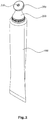
- FIG.2 is an assembled perspective view illustrating a configuration of a tube container equipped with a metal applicator according to an exemplary embodiment of the present invention.
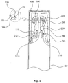
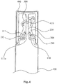
- Figs.3 and 4 are cross-sectional views illustrating a configuration of a tube container equipped with a metal applicator according to an exemplary embodiment of the present invention.
- Fig.5 is an explanatory view illustrating configuration of a part and a support body of a tube container equipped with a metal applicator according to an exemplary embodiment of the present invention.
- Fig.6 is an explanatory view illustrating a size configuration of an applicator and a support body of the tube container equipped with a metal applicator according to an exemplary embodiment of the present invention.
- a tube container equipped with a metal applicator includes a tube body 100, a support body 200, an applicator 300, and an overcap 400.
- Contents are contained into the container body (100), on whose upper portion a tube neck 110 having a outlet part 111a that discharges the contents is coupled, and on the center of the outlet part 111 is coupled a discharging hole 111a to which contents contained in the tube container body 100 is discharged.
- a rotation preventing protrusion 111b which prevents a support body 200 from rotating, and the rotation preventing protrusion 111b, coupled with a coupling groove 211, prevents the support body 200 from rotating and simultaneously guides combining direction when coupling the support body 200 to the outlet part 111.
- a fixing protrusion 111c is formed, encircling the outer circumferential surface, on the outlet part 111 so as to prevent the support body 200 from being separated to upward direction after the support body 200 is coupled.
- the support body 200 supports an applicator 300, and comprises a passage where the contents discharged through the outlet part 111 flows, and further includes a fixing part 210, a contents movement tube 220, a coupling part 230, and a hollow part 240.
- the fixing part 210 is coupled with the outlet portion on the inner lower portion of the support body 200 as encircling the outlet part 111 and fixes the support body 200 to the tube neck 110, wherein a coupling groove is built on the lower portion of the fixing part so as to be able to combine with the rotation preventing protrusion 111b and prevent the support body 200 from rotating.
- a protrusion 212 which meets the lower end of the fixing protrusion 111c in a state of the protrusion 212 being combined with the outlet part 111 and prevents the support body 200 from moving upward.
- the contents movement tube 220 is connected to the outlet part 111, and forms a passage longitudinally, so as to allow the contents discharged through the outlet part 111 to flow to the upper part.
- the coupling part 230 is formed with protrusion on the upper end of the support body 200, coupled with an applicator 300 and supports the applicator 300, wherein a securing protrusion 231 is formed, as encircling the outer circumferential, so that the applicator 300 may be secured.
- the securing protrusion 231 may have a fluent curve so that the applicator 300 can be attached and separated.
- the support body 200 has a narrow middle portion like an hourglass, wherein with the top end of the support body 200 forming a slope from one side to the other side, the applicator should be built obliquely, providing esthetic effect to the container.
- a hollow part 240 is formed from the upper side and toward the lower side of the support body 200, so that when combined with elastic fit the support body 200 may be pressed, not only enabling to be contracted, but also effectively compensating by the elasticity the difference of the volume change that is caused by the temperature difference and temperature change of the applicator 300 and the support body 200, and thereupon the applicator 300 and the support body 200 are contacted tightly each other all the time and maintain their firmly contacted state.
- the applicator 300 is coupled with a coupling protrusion 230 to be able to be attached and separated on the top end of the support body 200, and thereof on the center of the applicator 300, forms a contents discharging hole 310 which allows the contents to move through the contents movement tube 220 to the outside.
- the applicator 300 is made of metal, and thus it is possible to deliver heat or cold to the facial skin when applied, resulting in facilitating the metabolism of facial skin and improving the elasticity of the skin.
- the applicator 300 is formed in a circular shape in the state of bilateral symmetry with the contents discharging hole 310 in the center, and thereby it is possible to mass-produce with ease through NC manufacturing process and also to reduce expense due to no need of a separate mold.
- the applicator 300 can be manufactured through NC manufacturing process, so that it is possible not only to reduce the time required to grind and polish the applicator when post-processing but also to reduce post-processing expense.
- the support body 200 is made of thermoplastic resin and the applicator 300 is made of metal.
- this invention is usually used by contacting the applicator 300 directly to the facial skin after being warm or cool, the support body 200 and the applicator 300 are used under the condition of repeated temperature change.
- the temperature change of metal and thermoplastic resin are varied in size;
- the coefficient of thermal expansion of metal has a range of 5-25(unit: x0.000001/°C), such as brass 18.7, copper 18.0, cast iron 10.8, stainless steel 14.4 ⁇ '7.3
- thermoplastic resin (polymer) is 50 ⁇ 600(unit: x0.000001/°C), such as polypropylene 100 ⁇ 200, polyethylene 200, polystyrene(PS) 70, because thermoplastic resin has weak secondary intermolecular bonds and minimum cross-links.
- the size change of thermoplastic resin is bigger than that of metal, and thereby the difference of size change occurs.
- the bonding structure between the support body 200 made of two kinds of material and the applicator 300 may get weaker or be separated, and also the gap between them may arise; thereby, undesirable results such as linkage of contents may occur.
- the outer radius (DI) of the coupling part 231 under the lowest usable temperature should be the same or bigger than the inner radius (DI) of the depression coupling part 320 under the ordinary usable temperature, as shown in Fig. 6 .
- the support body 200 when the temperature rises, the support body 200 has bigger size increase according to the temperature change than the applicator 300 (in other words, when the outer radius(DI) of the coupling part 231 according to the temperature rise change gets bigger than the inner radius (DO) of the depression coupling part 320), leading the hollow part 340 to efficiently offset the difference of volume change by elasticity and then despite the temperature change and temperature difference, the applicator 300 and the support body 200 are able to contact each other and maintain combining state.
- the reduction of the support body 200 is much bigger than that of the applicator 300, and whereupon, the space between the support body 200 and the applicator 300 should arise, and thereby bonding structure may become weaker or separation may occur.
- the applicator 300 touches a user's skin and is used, the applicator 300 having high coefficient of heat conduction gets to the temperature (this is called "ordinary usable temperature") of the user's skin with relatively rapid speed, and the size of the applicator increases rapidly, whereas the temperature rise of the support body 200 having low coefficient of heat conduction falls behind, and as a result, the size increase of the support body 200 is delayed, causing the gap between the support body 200 and the applicator 300 to arise, leading to the weakness of the bonding structure and the separation.
- these problems can be solved by setting the outer radius (DI) of the coupling part 231 under the lowest usable temperature (Generally, this is the temperature on which contents can be kept refrigerated without being deteriorated such as congelation.) to the same or bigger than the inner radius of the depression coupling part 320 under the ordinary usable temperature.
- the outer radius (DI) of the coupling part 231 and the inner radius (DO) of the depression coupling part 320 should be measured in the state where they are not coupled and separated respectively, and those measurements should be used.
- the outer radius (DI) of the coupling part 231 is set to be the same or bigger than the inner radius (DO) of the depression coupling part 320, and thus, always has a bigger measurement than that of the depression coupling part 320 under the same lowest usable temperature.
- the outer radius (DI) of the coupling part 231 has the same or at least bigger measurement than the inner radius (DO) of the depression coupling part 320.
- the outer radius (DI) of the coupling part 231 is at least the same or bigger than the inner radius (DO) of the depression coupling part 320, and therefore, prevents the gap between the support body 200 and the applicator 300 from being generated, leading to preventing bonding structure from being weakened or separated, or fundamentally prevents the contents from being leaked.
- the support body 20 undergo an elastic deformation by the hollow part 240, with the support body 200 and the applicator 300 under the state of being coupled each other as shown in Figs 3 or 4 ; thereby, the outer radius (DI) of the coupling part 231 is made to fit to the inner radius (DO) of the depression coupling part 320, and as a result, the support body 200 and the applicator 300 can be maintained in the state of being coupled tightly.
- the overcap 400 encircles the support body 200 and the applicator 300 and is coupled to the tube neck 110, wherein an opening and closing hole 410 is provided with protrusion on the inner top of the overcap 400, so as to enable the contents discharging hole 310 to open and close.
Landscapes
- Engineering & Computer Science (AREA)
- Mechanical Engineering (AREA)
- Closures For Containers (AREA)
- Containers And Packaging Bodies Having A Special Means To Remove Contents (AREA)
- Tubes (AREA)
Abstract
Description
- The present invention disclosed herein relates to a tube container equipped with a metal applicator, and more particularly, a tube container equipped with a metal applicator which is attached on the top portion of the tube container, so that when contents are applied onto the skin it is possible for the metal applicator to deliver heat or cold to the skin and facilitate metabolism of the facial skin, as improving its elasticity.
- Generally, a tube container comprises a tube body containing contents, a tube neck comprising an outlet part that is coupled to an upper portion of the tube body, as supporting the tube body and allowing the contents contained in the tube body to be discharged into, and an overcap that is coupled detachably to the tube neck and opens and closes the outlet part.
- The tube containers as above, wherein contents are discharged through the outlet part when the tube container is pressurized, as shown in
Fig. 1 of patent registration no. 10-1057333, has an applicator, which is coupled to a tube upper structure (120), like a brush (140) which sucks contents and discharges to the outside to allow contents to be applied easily over the skin. - Recently, as interest in skincare increases, it is hard to obtain satisfying absorbance and skincare effect only by absorbing the contents, so that there have been tried a variety of methods that can apply heat or cold onto a face in order to facilitate metabolism of the facial skin and improve its elasticity; however, the said registered patent has a structure wherein contents are sucked from the contain body and discharged through the brush (140), and thus it is hard for heat or coldness to be delivered onto the facial skin.
- Meanwhile, to satisfy customers' need such as the described above, hot and cold maskpack devices for serving as hot or cold maskpack are manufactured and released commercially. However, since the structure of these products is complicated and thereby manufacturing cost is high, they are not widely utilized.
- Accordingly, a simple structured cosmetic container is needed that can deliver heat or cold onto the skin when the contents is applied.
- Meanwhile, the applicator that can deliver heat or cold onto the skin when applying the contents are usually made of metal, while a support body that supports the applicator is usually made of thermoplastic resin; however, there is a big gap in the deformation rate against temperature change between metal and thermoplastic resin, and the coupling structure of two parts becomes loose or separated, leading to a problem that contents may be licked through an opening.
- The present invention is devised to solve the said problems above, and its goal is to equip a metal applicator, which will be contacted to the skin, on the top of a tube container, so that when the contents are applied onto the skin, it is possible to deliver heat or cold onto facial skin, leading to facilitating the metabolism of the facial skin and improving its elasticity.
- Furthermore, the present invention is related to a tube container equipped with a metal applicator that is manufactured in the circular shape through NC manufacturing process and is able to be attached and detached on the top of the support body, thereby possible to lower manufacturing cost and also to mass-produce due to no need of a separate mold for producing an applicator.
- Meanwhile, there is a task to be solved, which is to make the strong bond between the applicator and the support body, even though the metal applicator and the support body made of thermoplastic resin change differently in size according to temperature change.
- To solve the above problems, a tube container equipped with a metal applicator according to the present invention comprises a
tube body 100 which contains contents inside and on whose top atube neck 110 is combined in order for contents to be discharged; asupport body 200, made of thermoplastic resin, which is combined to the top of the said tube neck and forms a passage wherein contents moves through theoutlet part 111; a metal applicator which is combined on the top of thetube neck 110 with insertion combination; and anovercap 400, encircling thesupport body 200 and theapplicator 300 and combined to thetube neck 110, which comprises an opening and closingpart 410 that opens and closes acontent discharging hole 310 of its inside. - The said
support body 200 comprises afixing part 210 which fixes the support body to thetube neck 110, while encircling theoutlet part 111 on the inner lower portion of thesupport body 200 and combined to the tube neck110; acontents movement tube 220 connected with theoutlet part 111 and forming a passage wherein contents discharged through theoutlet part 111 flows in; acoupling part 230 built on the upper end with protrusion and coupled with theapplicator 300, wherein asecuring protrusion 231 is formed, encircling the outer circumferential surface for theapplicator 300 to be secured; and ahollow part 240 which is formed from the upper portion to the lower portion of thesupport body 200. - The
applicator 300 comprises adepression coupling part 300, wherein thesecuring protrusion 231 is inserted and combined to the lower side of theapplicator 300, and acoupling protrusion 330 which forms along the inner circumferential surface in order for the securingprotrusion 231 to secure on the lower side of thedepression coupling part 320. - The outer radius of the
coupling part 230 under the lowest usable temperature is the same or bigger than the inner radius of thedepression coupling part 320 under the ordinary usable temperature. - Furthermore, on the lower portion of outer circumferential surface of the
outlet part 111 is formed arotation preventing protrusion 111b which guides the combining direction of thesupport body 200 and simultaneously prevents the rotation. - Furthermore, on the lower end of the
fixing part 210 is formed a coupling groove 211 which is coupled with therotation preventing protrusion 111b. - Furthermore, on the
outlet part 111 is formed afixing protrusion 111c which encircles the outer circumferential surface to prevent thesupport body 200 from being separated upward, and aprotrusion 212 which meets the lower end of thefixing protrusion 111c is formed on the lower inner portion of thefixing part 210. - According to the present invention as described on the above, the present invention has an advantage in that, when applied on the face, by equipping on the tube container a metal applicator contacted onto facial skin, it is possible to apply heat or cold and thereby to facilitate its metabolism and improve its elasticity.
- Furthermore, through NC manufacturing process, by manufacturing a metal applicator into a circular shape that can be attached and separated on the upper portion of the support body, the present invention does not need a separate mold to build an applicator; therefore, it is possible to reduce manufacturing cost and also to mass-produce in a short time.
- In addition, in the metal applicator and the support body that are coupled by the hollow part with elastic insertion combination, despite the difference of the size change of the metal applicator and the support body which is thermoplastic resin, the strong combination between the metal applicator and the support body is still possible.
-
-
Fig.1 is a exploded perspective view illustrating a configuration of a tube container equipped with a metal applicator according to an exemplary embodiment of the present invention; -
Fig.1 is an assembled perspective view illustrating a configuration of a tube container equipped with a metal applicator according to an exemplary embodiment of the present invention. -
Fig.3 and4 are cross-sectional views illustrating a configuration of a tube container equipped with a metal applicator according to an exemplary embodiment of the present invention. -
Fig.5 is an explanatory view illustrating a combination of an outlet part and a support body of the tube container equipped with a metal applicator according to an exemplary embodiment of the present invention. -
Fig.6 is an explanatory view illustrating a size configuration of an applicator and a support body of the tube container equipped with a metal applicator according to an exemplary embodiment of the present invention. - Hereinafter, exemplary embodiments of the present invention will be described in detail with reference to the accompanying drawings. The same reference numerals provided in the drawings indicate the same members.
-
FIG.1 is an exploded perspective view illustrating a configuration of a tube container equipped with a metal applicator according to an exemplary embodiment of the present invention.FIG.2 is an assembled perspective view illustrating a configuration of a tube container equipped with a metal applicator according to an exemplary embodiment of the present invention. -
Figs.3 and4 are cross-sectional views illustrating a configuration of a tube container equipped with a metal applicator according to an exemplary embodiment of the present invention.Fig.5 is an explanatory view illustrating configuration of a part and a support body of a tube container equipped with a metal applicator according to an exemplary embodiment of the present invention. -
Fig.6 is an explanatory view illustrating a size configuration of an applicator and a support body of the tube container equipped with a metal applicator according to an exemplary embodiment of the present invention. - Referring to
Figs.1 to 4 , a tube container equipped with a metal applicator according to an exemplary embodiment of the present invention includes atube body 100, asupport body 200, anapplicator 300, and anovercap 400. - Contents are contained into the container body (100), on whose upper portion a
tube neck 110 having aoutlet part 111a that discharges the contents is coupled, and on the center of theoutlet part 111 is coupled adischarging hole 111a to which contents contained in thetube container body 100 is discharged. - Regarding to the present invention, on the lower outer circumferential surface of the
outlet part 111 is formed arotation preventing protrusion 111b which prevents asupport body 200 from rotating, and therotation preventing protrusion 111b, coupled with a coupling groove 211, prevents thesupport body 200 from rotating and simultaneously guides combining direction when coupling thesupport body 200 to theoutlet part 111. - Meanwhile, it is preferred that a
fixing protrusion 111c is formed, encircling the outer circumferential surface, on theoutlet part 111 so as to prevent thesupport body 200 from being separated to upward direction after thesupport body 200 is coupled. - The
support body 200, made of thermoplastic resin, supports anapplicator 300, and comprises a passage where the contents discharged through theoutlet part 111 flows, and further includes afixing part 210, acontents movement tube 220, acoupling part 230, and ahollow part 240. - The
fixing part 210 is coupled with the outlet portion on the inner lower portion of thesupport body 200 as encircling theoutlet part 111 and fixes thesupport body 200 to thetube neck 110, wherein a coupling groove is built on the lower portion of the fixing part so as to be able to combine with therotation preventing protrusion 111b and prevent thesupport body 200 from rotating. - Furthermore, on the inner lower portion of the
fixing part 210 is formed aprotrusion 212, which meets the lower end of thefixing protrusion 111c in a state of theprotrusion 212 being combined with theoutlet part 111 and prevents thesupport body 200 from moving upward. - The
contents movement tube 220 is connected to theoutlet part 111, and forms a passage longitudinally, so as to allow the contents discharged through theoutlet part 111 to flow to the upper part. - The
coupling part 230 is formed with protrusion on the upper end of thesupport body 200, coupled with anapplicator 300 and supports theapplicator 300, wherein asecuring protrusion 231 is formed, as encircling the outer circumferential, so that theapplicator 300 may be secured. - It is preferred that the
securing protrusion 231 may have a fluent curve so that theapplicator 300 can be attached and separated. - Meanwhile, the
support body 200 has a narrow middle portion like an hourglass, wherein with the top end of thesupport body 200 forming a slope from one side to the other side, the applicator should be built obliquely, providing esthetic effect to the container. - Furthermore, as shown in
Figs. 3 and4 , it is preferred that ahollow part 240 is formed from the upper side and toward the lower side of thesupport body 200, so that when combined with elastic fit thesupport body 200 may be pressed, not only enabling to be contracted, but also effectively compensating by the elasticity the difference of the volume change that is caused by the temperature difference and temperature change of theapplicator 300 and thesupport body 200, and thereupon theapplicator 300 and thesupport body 200 are contacted tightly each other all the time and maintain their firmly contacted state. - The
applicator 300 is coupled with acoupling protrusion 230 to be able to be attached and separated on the top end of thesupport body 200, and thereof on the center of theapplicator 300, forms acontents discharging hole 310 which allows the contents to move through thecontents movement tube 220 to the outside. - According to the present invention, the
applicator 300 is made of metal, and thus it is possible to deliver heat or cold to the facial skin when applied, resulting in facilitating the metabolism of facial skin and improving the elasticity of the skin. - Furthermore, the
applicator 300 is formed in a circular shape in the state of bilateral symmetry with thecontents discharging hole 310 in the center, and thereby it is possible to mass-produce with ease through NC manufacturing process and also to reduce expense due to no need of a separate mold. - Furthermore, the
applicator 300 can be manufactured through NC manufacturing process, so that it is possible not only to reduce the time required to grind and polish the applicator when post-processing but also to reduce post-processing expense. - Meanwhile, the
support body 200 is made of thermoplastic resin and theapplicator 300 is made of metal. In this case, since this invention is usually used by contacting theapplicator 300 directly to the facial skin after being warm or cool, thesupport body 200 and theapplicator 300 are used under the condition of repeated temperature change. - In this case, the temperature change of metal and thermoplastic resin are varied in size; the coefficient of thermal expansion of metal has a range of 5-25(unit: x0.000001/°C), such as brass 18.7, copper 18.0, cast iron 10.8, stainless steel 14.4∼'7.3, whereas the coefficient of thermal expansion of thermoplastic resin (polymer) is 50∼600(unit: x0.000001/°C), such as
polypropylene 100∼200,polyethylene 200, polystyrene(PS) 70, because thermoplastic resin has weak secondary intermolecular bonds and minimum cross-links. In other words, under the conditions of the same temperature change, the size change of thermoplastic resin is bigger than that of metal, and thereby the difference of size change occurs. - Accordingly, the bonding structure between the
support body 200 made of two kinds of material and theapplicator 300 may get weaker or be separated, and also the gap between them may arise; thereby, undesirable results such as linkage of contents may occur. To prevent those problems, it is preferred that the outer radius (DI) of thecoupling part 231 under the lowest usable temperature should be the same or bigger than the inner radius (DI) of thedepression coupling part 320 under the ordinary usable temperature, as shown inFig. 6 . - That is, as described above, when the temperature rises, the
support body 200 has bigger size increase according to the temperature change than the applicator 300 (in other words, when the outer radius(DI) of thecoupling part 231 according to the temperature rise change gets bigger than the inner radius (DO) of the depression coupling part 320), leading the hollow part 340 to efficiently offset the difference of volume change by elasticity and then despite the temperature change and temperature difference, theapplicator 300 and thesupport body 200 are able to contact each other and maintain combining state. - Meanwhile, when temperature drops as in the present invention, the reduction of the
support body 200 is much bigger than that of theapplicator 300, and whereupon, the space between thesupport body 200 and theapplicator 300 should arise, and thereby bonding structure may become weaker or separation may occur. - Furthermore, when the
applicator 300 touches a user's skin and is used, theapplicator 300 having high coefficient of heat conduction gets to the temperature (this is called "ordinary usable temperature") of the user's skin with relatively rapid speed, and the size of the applicator increases rapidly, whereas the temperature rise of thesupport body 200 having low coefficient of heat conduction falls behind, and as a result, the size increase of thesupport body 200 is delayed, causing the gap between thesupport body 200 and theapplicator 300 to arise, leading to the weakness of the bonding structure and the separation. - As shown in
Fig. 6 , these problems can be solved by setting the outer radius (DI) of thecoupling part 231 under the lowest usable temperature (Generally, this is the temperature on which contents can be kept refrigerated without being deteriorated such as congelation.) to the same or bigger than the inner radius of thedepression coupling part 320 under the ordinary usable temperature. Herein, the outer radius (DI) of thecoupling part 231 and the inner radius (DO) of thedepression coupling part 320 should be measured in the state where they are not coupled and separated respectively, and those measurements should be used. - In other words, when kept refrigerated under the lowest usable temperature, the outer radius (DI) of the
coupling part 231 is set to be the same or bigger than the inner radius (DO) of thedepression coupling part 320, and thus, always has a bigger measurement than that of thedepression coupling part 320 under the same lowest usable temperature. - Meanwhile, while using, even when the
applicator 300 rises in relatively rapid speed and thesupport body 200 is still under the lowest usable temperature, the outer radius (DI) of thecoupling part 231 has the same or at least bigger measurement than the inner radius (DO) of thedepression coupling part 320. - Hereforth, when both temperatures of the
applicator 300 and thesupport body 200 rise above the lowest usable temperature, then again the outer radius (DI) of thecoupling part 231 always gets to have bigger or at least the same measurement than the inner radius (DO) of thedepression coupling part 320. - Accordingly, under any temperature change, the outer radius (DI) of the
coupling part 231 is at least the same or bigger than the inner radius (DO) of thedepression coupling part 320, and therefore, prevents the gap between thesupport body 200 and theapplicator 300 from being generated, leading to preventing bonding structure from being weakened or separated, or fundamentally prevents the contents from being leaked. - Meanwhile, when the outer radius (DI) of the
coupling part 231 is always bigger or has the same features (this means when thesupport body 200 and theapplicator 300 are separated, meaning the same as previously described) than the inner radius (DO) of thedepression coupling part 320, the support body 20 undergo an elastic deformation by thehollow part 240, with thesupport body 200 and theapplicator 300 under the state of being coupled each other as shown inFigs 3 or4 ; thereby, the outer radius (DI) of thecoupling part 231 is made to fit to the inner radius (DO) of thedepression coupling part 320, and as a result, thesupport body 200 and theapplicator 300 can be maintained in the state of being coupled tightly. - The
overcap 400 encircles thesupport body 200 and theapplicator 300 and is coupled to thetube neck 110, wherein an opening andclosing hole 410 is provided with protrusion on the inner top of theovercap 400, so as to enable thecontents discharging hole 310 to open and close. - As described above, optimal embodiments have been disclosed in the drawings and the specification. Although specific terms have been used herein, these are only intended to describe the present invention and are not intended to limit the meanings of the terms or to restrict the scope of the present invention as disclosed in the accompanying claims. Therefore, those skilled in the art will appreciate that various modifications and other equivalent embodiments are possible from the above embodiments. Therefore, the scope of the present invention should be defined by the technical spirit of the accompanying claims.
Claims (4)
- A tube container with a metal applicator comprising:a tube body (100), wherein contents are held and a tube neck (110) coupled with an outlet part (111) is formed on an upper portion thereof, so that the contents may be discharged;a support body (200), made of thermoplastic resin and coupled on the tube neck (110), comprising a passage wherein the contents move through the outlet part (111);an applicator (300), made of metal, coupled on the upper end of the support body (200) with elastic fit, and comprising a contents discharging hole (310), wherein the contents in the middle is discharged to the outside; andan overcap (400), coupled on the tube neck (110), while encircling the support body (200) and the applicator (300), wherein an opening and closing hole (410) which opens and closes the contents discharging hole (310),wherein the support body (200) comprising:a fixing part (210) encircling the outlet part (111) at an inner lower portion of the support body (200) and engaged, thereby fixing the support body (200) into the tube neck (110);a contents discharging tube (220) connected to the outlet part (111) and forming a passage wherein the contents discharged out through the outlet part (111) flows;a coupling part (230) engaged on an upper end of the support body (200) with protrusion and combined with the applicator (300), wherein a securing protrusion (231) is formed, encircling the outer circumferential surface so that the applicator (300) may be secured; anda hollow part (240) formed from an upper portion of the support body (200) towards a lower portion,wherein the applicator (300) comprising:a depression coupling part (320) engaged on the lower portion of the applicator, with the securing protrusion inserted; anda coupling protrusion (330) formed along the inner circumferential surface so that the securing protrusion (231) may be caught at the lower portion of the depression coupling part (320),wherein the outer radius of the coupling part (231) under the lowest usable temperature is the same or bigger than the inner radius of the depression coupling part (320) under the ordinary usable temperature.
- The tube container with a metal applicator (300) of claim 1, wherein the rotation preventing protrusion (111b) is formed at a lower portion of the outer circumferential surface of the outlet part (111) so as to guide combining direction and at the same time to prevent the rotation of the support body (200).
- The tube container with a metal applicator of claim 2, wherein a coupling groove (211) is combined with the rotation preventing protrusion (111b) at a lower end of the fixing part (210).
- The tube container with a metal applicator (300) of claim 3, wherein a fixing protrusion (111c) is formed, encircling the outer circumferential surface, at the outlet part (111) so as to prevent the support body (200) from being separated; and a protrusion (212) is formed at the inner lower portion of the fixing part (210) confronting at the end of the fixing protrusion (111c).
Applications Claiming Priority (2)
| Application Number | Priority Date | Filing Date | Title |
|---|---|---|---|
| KR20140139961A KR101473191B1 (en) | 2014-10-16 | 2014-10-16 | Tube vessel with a metal applicator |
| PCT/KR2014/010154 WO2016060313A1 (en) | 2014-10-16 | 2014-10-28 | Tube container provided with metal applicator |
Publications (2)
| Publication Number | Publication Date |
|---|---|
| EP3207819A1 true EP3207819A1 (en) | 2017-08-23 |
| EP3207819A4 EP3207819A4 (en) | 2018-05-02 |
Family
ID=52679002
Family Applications (1)
| Application Number | Title | Priority Date | Filing Date |
|---|---|---|---|
| EP14904074.3A Withdrawn EP3207819A4 (en) | 2014-10-16 | 2014-10-28 | Tube container provided with metal applicator |
Country Status (6)
| Country | Link |
|---|---|
| US (1) | US9681728B2 (en) |
| EP (1) | EP3207819A4 (en) |
| JP (1) | JP2017533154A (en) |
| KR (1) | KR101473191B1 (en) |
| CN (1) | CN105722426A (en) |
| WO (1) | WO2016060313A1 (en) |
Families Citing this family (24)
| Publication number | Priority date | Publication date | Assignee | Title |
|---|---|---|---|---|
| KR101556652B1 (en) * | 2013-04-10 | 2015-10-01 | (주)연우 | Tube vessel with an applicator |
| US9578949B2 (en) * | 2013-06-24 | 2017-02-28 | HCT Group Holdings Limited | Dispenser with threaded tip/dispenser with removable cap |
| FR3009208B1 (en) * | 2013-07-31 | 2018-04-27 | Aptar France Sas | HEAD OF DISTRIBUTION AND APPLICATION |
| KR101511120B1 (en) * | 2014-04-11 | 2015-05-15 | (주)연우 | Tube vessel with an applicator |
| KR101896036B1 (en) * | 2016-11-17 | 2018-09-06 | (주)연우 | Turning type cosmetic vessel |
| EP3582650A1 (en) * | 2017-02-17 | 2019-12-25 | Porex Corporation | Liquid applicator and device |
| KR101808284B1 (en) * | 2017-03-22 | 2017-12-12 | (주)연우 | Tube vessel with an applicator |
| KR101823518B1 (en) | 2017-05-30 | 2018-01-30 | 주식회사 승일 | Aerosol can having flower cap |
| CN107280209A (en) * | 2017-08-23 | 2017-10-24 | 上虞圣瑞斯包装有限公司 | A kind of ball ball support of resistance to essential oil corrosion |
| US10561220B2 (en) * | 2017-11-08 | 2020-02-18 | Arvin Abadilla | Applicator |
| KR101954033B1 (en) * | 2018-10-02 | 2019-03-04 | 윤동준 | An applicator for cosmetic |
| US11140966B2 (en) * | 2018-11-19 | 2021-10-12 | HCT Group Holdings Limited | Rounded tip applicator |
| USD910236S1 (en) * | 2018-11-20 | 2021-02-09 | HCT Group Holdings Limited | Ball tip applicator |
| USD902035S1 (en) * | 2019-03-14 | 2020-11-17 | Yonwoo Co., Ltd. | Container for cosmetics |
| US11957230B2 (en) | 2019-06-23 | 2024-04-16 | Toly Management Ltd. | Cosmetic applicator with heat transfer component |
| US11219292B2 (en) | 2019-06-23 | 2022-01-11 | Toly Managment Ltd. | Cosmetic applicator with heat transfer component |
| CN113347904B (en) * | 2020-05-25 | 2022-04-26 | 韩国科玛株式会社 | Contents container |
| KR200492726Y1 (en) * | 2020-05-25 | 2020-12-01 | 한국콜마주식회사 | Container |
| USD952247S1 (en) * | 2020-09-08 | 2022-05-17 | Parfums Christian Dior | Device for applying cosmetic products |
| JP1707663S (en) * | 2020-10-09 | 2022-02-16 | Cosmetic application | |
| USD988593S1 (en) * | 2020-11-23 | 2023-06-06 | Yonwoo Co., Ltd. | Cosmetic applicator |
| USD977986S1 (en) | 2022-06-11 | 2023-02-14 | Elc Management Llc | Tube with cap |
| USD1126007S1 (en) * | 2025-04-16 | 2026-05-12 | Anhui Redfoxpack Technology Co., Ltd. | Cosmetic packaging tube |
| KR102936966B1 (en) | 2025-07-28 | 2026-03-12 | 한국콜마주식회사 | Container having an applicator |
Family Cites Families (10)
| Publication number | Priority date | Publication date | Assignee | Title |
|---|---|---|---|---|
| JPH11247869A (en) * | 1998-02-27 | 1999-09-14 | Toyota Motor Corp | Bearing mounting structure and mounting method |
| JP3796258B2 (en) * | 2004-11-10 | 2006-07-12 | 株式会社トキワ | Liquid filling extrusion container |
| FR2909544B1 (en) * | 2006-12-07 | 2009-08-28 | Oreal | COOLING DEVICE |
| US7883287B2 (en) * | 2007-05-10 | 2011-02-08 | HCT Asia, Ltd | Dispenser with thermal storage tip |
| CN201367172Y (en) * | 2009-01-21 | 2009-12-23 | 黄天发 | Can casing cover provided with locking teeth |
| ES2662532T3 (en) * | 2009-06-04 | 2018-04-06 | Elc Management Llc | Metal coated ceramic cosmetic applicator |
| CN202163704U (en) * | 2011-07-29 | 2012-03-14 | 程继鸣 | Plastic cover with metal seal shell |
| KR200466894Y1 (en) * | 2011-10-24 | 2013-05-13 | (주)아모레퍼시픽 | Case having contents application cap with heat insulation function |
| WO2014109468A1 (en) * | 2013-01-08 | 2014-07-17 | (주)연우 | Tubular container having metal applicator |
| KR101411990B1 (en) * | 2014-03-14 | 2014-06-26 | (주)연우 | Tube vessel with a applicator |
-
2014
- 2014-10-16 KR KR20140139961A patent/KR101473191B1/en not_active Expired - Fee Related
- 2014-10-28 JP JP2017540531A patent/JP2017533154A/en active Pending
- 2014-10-28 EP EP14904074.3A patent/EP3207819A4/en not_active Withdrawn
- 2014-10-28 CN CN201480002539.9A patent/CN105722426A/en active Pending
- 2014-10-28 US US14/759,348 patent/US9681728B2/en not_active Expired - Fee Related
- 2014-10-28 WO PCT/KR2014/010154 patent/WO2016060313A1/en not_active Ceased
Also Published As
| Publication number | Publication date |
|---|---|
| EP3207819A4 (en) | 2018-05-02 |
| WO2016060313A1 (en) | 2016-04-21 |
| JP2017533154A (en) | 2017-11-09 |
| KR101473191B1 (en) | 2014-12-24 |
| CN105722426A (en) | 2016-06-29 |
| US9681728B2 (en) | 2017-06-20 |
| US20160249726A1 (en) | 2016-09-01 |
Similar Documents
| Publication | Publication Date | Title |
|---|---|---|
| US9681728B2 (en) | Tube container with a metal applicator | |
| EP3348175B1 (en) | Cup | |
| US10010151B2 (en) | Packaging and applicator device for applying a cosmetic composition to the lips | |
| EP3735149B1 (en) | Packaging service capsule for cosmetic product, and associated packaging device | |
| US20140263474A1 (en) | Dispensing closure | |
| US9289048B2 (en) | Cosmetic multi-layered wiper | |
| US10717591B2 (en) | Container for icecream | |
| CN105764806B (en) | The packaging system of cosmetic product dispensing head and correlation including wiper member | |
| MX2013014429A (en) | A one-piece closure for equipping a container. | |
| US11203468B2 (en) | Pouring spout of container | |
| KR20180052557A (en) | Lid | |
| EP2474482B1 (en) | Container with improved opening system | |
| US20180111725A1 (en) | Collapsible fluid dispensing package and valve fitment for dispensing fluid such as foodstuffs | |
| CN103096863B (en) | Single-use applicator | |
| US20180134451A1 (en) | Drinking cup structure | |
| US9681729B2 (en) | Tube head for provision and application of a liquid and tube with such a tube head | |
| US11414248B2 (en) | Dispenser with a membrane for sachets | |
| CN206719862U (en) | Tubular container | |
| US20200095038A1 (en) | Adhesively closed packaging systems | |
| US11731810B2 (en) | Inverted dispensing container | |
| WO2015009179A1 (en) | Closure with an elastically deformable element | |
| RU2664218C1 (en) | Plastic container for a food product, having various brittle ventilation holes | |
| US20170029175A1 (en) | Liquid Dispensing Device | |
| JP6327458B2 (en) | Two-material hinge cap | |
| JP2016222252A (en) | Spout |
Legal Events
| Date | Code | Title | Description |
|---|---|---|---|
| PUAI | Public reference made under article 153(3) epc to a published international application that has entered the european phase |
Free format text: ORIGINAL CODE: 0009012 |
|
| STAA | Information on the status of an ep patent application or granted ep patent |
Free format text: STATUS: REQUEST FOR EXAMINATION WAS MADE |
|
| 17P | Request for examination filed |
Effective date: 20160706 |
|
| AK | Designated contracting states |
Kind code of ref document: A1 Designated state(s): AL AT BE BG CH CY CZ DE DK EE ES FI FR GB GR HR HU IE IS IT LI LT LU LV MC MK MT NL NO PL PT RO RS SE SI SK SM TR |
|
| AX | Request for extension of the european patent |
Extension state: BA ME |
|
| DAX | Request for extension of the european patent (deleted) | ||
| A4 | Supplementary search report drawn up and despatched |
Effective date: 20180329 |
|
| RIC1 | Information provided on ipc code assigned before grant |
Ipc: B65D 41/16 20060101ALI20180323BHEP Ipc: B65D 35/44 20060101ALI20180323BHEP Ipc: A45D 34/00 20060101ALI20180323BHEP Ipc: B65D 35/10 20060101ALI20180323BHEP Ipc: B65D 35/36 20060101ALI20180323BHEP Ipc: A45D 34/04 20060101AFI20180323BHEP |
|
| STAA | Information on the status of an ep patent application or granted ep patent |
Free format text: STATUS: THE APPLICATION IS DEEMED TO BE WITHDRAWN |
|
| 18D | Application deemed to be withdrawn |
Effective date: 20181030 |