EP3207313B1 - Sealing device for a gas turbine combustor - Google Patents
Sealing device for a gas turbine combustor Download PDFInfo
- Publication number
- EP3207313B1 EP3207313B1 EP15850671.7A EP15850671A EP3207313B1 EP 3207313 B1 EP3207313 B1 EP 3207313B1 EP 15850671 A EP15850671 A EP 15850671A EP 3207313 B1 EP3207313 B1 EP 3207313B1
- Authority
- EP
- European Patent Office
- Prior art keywords
- flow
- combustion
- compressible seal
- combustion liner
- wall
- Prior art date
- Legal status (The legal status is an assumption and is not a legal conclusion. Google has not performed a legal analysis and makes no representation as to the accuracy of the status listed.)
- Not-in-force
Links
Images







Classifications
-
- F—MECHANICAL ENGINEERING; LIGHTING; HEATING; WEAPONS; BLASTING
- F23—COMBUSTION APPARATUS; COMBUSTION PROCESSES
- F23R—GENERATING COMBUSTION PRODUCTS OF HIGH PRESSURE OR HIGH VELOCITY, e.g. GAS-TURBINE COMBUSTION CHAMBERS
- F23R3/00—Continuous combustion chambers using liquid or gaseous fuel
- F23R3/42—Continuous combustion chambers using liquid or gaseous fuel characterised by the arrangement or form of the flame tubes or combustion chambers
- F23R3/60—Support structures; Attaching or mounting means
-
- F—MECHANICAL ENGINEERING; LIGHTING; HEATING; WEAPONS; BLASTING
- F01—MACHINES OR ENGINES IN GENERAL; ENGINE PLANTS IN GENERAL; STEAM ENGINES
- F01D—NON-POSITIVE DISPLACEMENT MACHINES OR ENGINES, e.g. STEAM TURBINES
- F01D9/00—Stators
- F01D9/02—Nozzles; Nozzle boxes; Stator blades; Guide conduits, e.g. individual nozzles
- F01D9/023—Transition ducts between combustor cans and first stage of the turbine in gas-turbine engines; their cooling or sealings
-
- F—MECHANICAL ENGINEERING; LIGHTING; HEATING; WEAPONS; BLASTING
- F23—COMBUSTION APPARATUS; COMBUSTION PROCESSES
- F23R—GENERATING COMBUSTION PRODUCTS OF HIGH PRESSURE OR HIGH VELOCITY, e.g. GAS-TURBINE COMBUSTION CHAMBERS
- F23R3/00—Continuous combustion chambers using liquid or gaseous fuel
- F23R3/002—Wall structures
-
- F—MECHANICAL ENGINEERING; LIGHTING; HEATING; WEAPONS; BLASTING
- F23—COMBUSTION APPARATUS; COMBUSTION PROCESSES
- F23R—GENERATING COMBUSTION PRODUCTS OF HIGH PRESSURE OR HIGH VELOCITY, e.g. GAS-TURBINE COMBUSTION CHAMBERS
- F23R3/00—Continuous combustion chambers using liquid or gaseous fuel
- F23R3/02—Continuous combustion chambers using liquid or gaseous fuel characterised by the air-flow or gas-flow configuration
-
- F—MECHANICAL ENGINEERING; LIGHTING; HEATING; WEAPONS; BLASTING
- F23—COMBUSTION APPARATUS; COMBUSTION PROCESSES
- F23R—GENERATING COMBUSTION PRODUCTS OF HIGH PRESSURE OR HIGH VELOCITY, e.g. GAS-TURBINE COMBUSTION CHAMBERS
- F23R3/00—Continuous combustion chambers using liquid or gaseous fuel
- F23R3/02—Continuous combustion chambers using liquid or gaseous fuel characterised by the air-flow or gas-flow configuration
- F23R3/04—Air inlet arrangements
-
- F—MECHANICAL ENGINEERING; LIGHTING; HEATING; WEAPONS; BLASTING
- F23—COMBUSTION APPARATUS; COMBUSTION PROCESSES
- F23R—GENERATING COMBUSTION PRODUCTS OF HIGH PRESSURE OR HIGH VELOCITY, e.g. GAS-TURBINE COMBUSTION CHAMBERS
- F23R3/00—Continuous combustion chambers using liquid or gaseous fuel
- F23R3/02—Continuous combustion chambers using liquid or gaseous fuel characterised by the air-flow or gas-flow configuration
- F23R3/04—Air inlet arrangements
- F23R3/06—Arrangement of apertures along the flame tube
- F23R3/08—Arrangement of apertures along the flame tube between annular flame tube sections, e.g. flame tubes with telescopic sections
-
- F—MECHANICAL ENGINEERING; LIGHTING; HEATING; WEAPONS; BLASTING
- F23—COMBUSTION APPARATUS; COMBUSTION PROCESSES
- F23R—GENERATING COMBUSTION PRODUCTS OF HIGH PRESSURE OR HIGH VELOCITY, e.g. GAS-TURBINE COMBUSTION CHAMBERS
- F23R3/00—Continuous combustion chambers using liquid or gaseous fuel
- F23R3/02—Continuous combustion chambers using liquid or gaseous fuel characterised by the air-flow or gas-flow configuration
- F23R3/04—Air inlet arrangements
- F23R3/10—Air inlet arrangements for primary air
-
- F—MECHANICAL ENGINEERING; LIGHTING; HEATING; WEAPONS; BLASTING
- F23—COMBUSTION APPARATUS; COMBUSTION PROCESSES
- F23R—GENERATING COMBUSTION PRODUCTS OF HIGH PRESSURE OR HIGH VELOCITY, e.g. GAS-TURBINE COMBUSTION CHAMBERS
- F23R3/00—Continuous combustion chambers using liquid or gaseous fuel
- F23R3/02—Continuous combustion chambers using liquid or gaseous fuel characterised by the air-flow or gas-flow configuration
- F23R3/26—Controlling the air flow
-
- F—MECHANICAL ENGINEERING; LIGHTING; HEATING; WEAPONS; BLASTING
- F23—COMBUSTION APPARATUS; COMBUSTION PROCESSES
- F23R—GENERATING COMBUSTION PRODUCTS OF HIGH PRESSURE OR HIGH VELOCITY, e.g. GAS-TURBINE COMBUSTION CHAMBERS
- F23R3/00—Continuous combustion chambers using liquid or gaseous fuel
- F23R3/42—Continuous combustion chambers using liquid or gaseous fuel characterised by the arrangement or form of the flame tubes or combustion chambers
- F23R3/46—Combustion chambers comprising an annular arrangement of several essentially tubular flame tubes within a common annular casing or within individual casings
-
- F—MECHANICAL ENGINEERING; LIGHTING; HEATING; WEAPONS; BLASTING
- F05—INDEXING SCHEMES RELATING TO ENGINES OR PUMPS IN VARIOUS SUBCLASSES OF CLASSES F01-F04
- F05D—INDEXING SCHEME FOR ASPECTS RELATING TO NON-POSITIVE-DISPLACEMENT MACHINES OR ENGINES, GAS-TURBINES OR JET-PROPULSION PLANTS
- F05D2240/00—Components
- F05D2240/55—Seals
-
- F—MECHANICAL ENGINEERING; LIGHTING; HEATING; WEAPONS; BLASTING
- F05—INDEXING SCHEMES RELATING TO ENGINES OR PUMPS IN VARIOUS SUBCLASSES OF CLASSES F01-F04
- F05D—INDEXING SCHEME FOR ASPECTS RELATING TO NON-POSITIVE-DISPLACEMENT MACHINES OR ENGINES, GAS-TURBINES OR JET-PROPULSION PLANTS
- F05D2240/00—Components
- F05D2240/55—Seals
- F05D2240/57—Leaf seals
-
- F—MECHANICAL ENGINEERING; LIGHTING; HEATING; WEAPONS; BLASTING
- F23—COMBUSTION APPARATUS; COMBUSTION PROCESSES
- F23R—GENERATING COMBUSTION PRODUCTS OF HIGH PRESSURE OR HIGH VELOCITY, e.g. GAS-TURBINE COMBUSTION CHAMBERS
- F23R2900/00—Special features of, or arrangements for continuous combustion chambers; Combustion processes therefor
- F23R2900/00012—Details of sealing devices
-
- F—MECHANICAL ENGINEERING; LIGHTING; HEATING; WEAPONS; BLASTING
- F23—COMBUSTION APPARATUS; COMBUSTION PROCESSES
- F23R—GENERATING COMBUSTION PRODUCTS OF HIGH PRESSURE OR HIGH VELOCITY, e.g. GAS-TURBINE COMBUSTION CHAMBERS
- F23R2900/00—Special features of, or arrangements for continuous combustion chambers; Combustion processes therefor
- F23R2900/03042—Film cooled combustion chamber walls or domes
-
- F—MECHANICAL ENGINEERING; LIGHTING; HEATING; WEAPONS; BLASTING
- F23—COMBUSTION APPARATUS; COMBUSTION PROCESSES
- F23R—GENERATING COMBUSTION PRODUCTS OF HIGH PRESSURE OR HIGH VELOCITY, e.g. GAS-TURBINE COMBUSTION CHAMBERS
- F23R2900/00—Special features of, or arrangements for continuous combustion chambers; Combustion processes therefor
- F23R2900/03043—Convection cooled combustion chamber walls with means for guiding the cooling air flow
-
- F—MECHANICAL ENGINEERING; LIGHTING; HEATING; WEAPONS; BLASTING
- F23—COMBUSTION APPARATUS; COMBUSTION PROCESSES
- F23R—GENERATING COMBUSTION PRODUCTS OF HIGH PRESSURE OR HIGH VELOCITY, e.g. GAS-TURBINE COMBUSTION CHAMBERS
- F23R2900/00—Special features of, or arrangements for continuous combustion chambers; Combustion processes therefor
- F23R2900/03044—Impingement cooled combustion chamber walls or subassemblies
Definitions
- the present invention relates generally to an apparatus and method for sealing an aft region of a gas turbine combustor. More specifically, the present invention provides an apparatus and method for controlling the amount of compressed air passed to a combustor for cooling and for mixing prior to injection in the combustion liner. The method is not subject-matter of the claims.
- Diffusion type nozzles where fuel is mixed with air external to the fuel nozzle by diffusion, proximate the flame zone. Diffusion type nozzles historically produce relatively high emissions due to the fact that the fuel and air burn essentially upon interaction, without mixing, and stoichiometrically at high temperature to maintain adequate combustor stability and low combustion dynamics.
- An alternate means of premixing fuel and air and obtaining lower emissions can occur by utilizing multiple combustion stages.
- the fuel and air which mix and burn to form the hot combustion gases, must also be staged.
- available power as well as emissions can be controlled.
- Fuel can be staged through a series of valves within the fuel system or dedicated fuel circuits to specific fuel injectors. Air, however, can be more difficult to stage given the large quantity of air supplied by the engine compressor.
- a number of modern day gas turbine combustion systems include a flow sleeve encompassing a combustion liner, where the flow sleeve can at least partially regulate the amount of air entering the combustion system.
- One such combustion system 100 is shown in FIGS. 1 and 2 .
- the combustion system 100 has a flow sleeve 102 encompassing a combustion liner 104.
- Air for cooling of the combustion liner 104 and for use in the combustion process is enters a channel 106 through a plurality of holes 108 and an open flow sleeve aft end 110. Such an arrangement has little way of controlling the amount of cooling air entering the passageway 106.
- FIG. 3 an alternate prior art combustion system 300 for controlling the flow of compressed air to the passageway 326 between the flow sleeve 302 and combustion liner 304 is depicted.
- the sealing interface between the combustion liner 304 and flow sleeve 302 is accomplished by a piston ring 308.
- the piston ring 308 has a cross sectional area sized to provide the proper preload to ensure sealing.
- this proper preload requires a large radial area to implement.
- Such radial area requirements can create implementation problems in addition to flow blockage issues due to their mere size. As a result, the flow blockages that can occur increase the pressure drop taken across this air inlet region, adversely affecting the performance of the combustion system.
- Patent Application US2011/252805 A1 can be regarded as representing the most pertinent prior art and discloses a sealing system for a gas turbine with the features of the preamble of claim 1.
- US2011/023496 A1 and US2005/262845 A1 disclose gas turbine combustor liner sealing systems.
- the present invention discloses an apparatus and method for regulating compressed air supply to a combustion system. More specifically, in an embodiment of the present invention, a sealing system for a gas turbine combustor as claimed in claim 1 is disclosed.
- the present invention discloses a system and method for regulating the flow of compressed air to a combustion system.
- a sealing system 400 for use in a gas turbine combustor is shown.
- the sealing system 400 comprises a combustion liner 402 positioned along a center axis A-A of a gas turbine combustor 404 and also includes a flow sleeve 406 positioned radially outward of the combustion liner 402, thereby forming an annular passage 408 between the combustion liner 402 and the flow sleeve 406.
- the sealing system 400 also comprises a compressible seal 410 positioned between the combustion liner 402 and the flow sleeve 406.
- the compressible seal 410 is shown in more detail in FIGS.
- the compressible seal 410 regulates an airflow passing through the seal 410 and into the annular passage 408.
- the compressible seal 410 serves to regulate airflow passing therethrough for cooling of combustion liner 402 and then into the combustion liner 402 for mixing with fuel.
- the compressible seal 410 provides a way of regulating the amount of cooling air permitted to pass into the annular passage 408 between the flow sleeve 406 and combustion liner 402.
- FIGS. 1-3 there was no type of flow restriction device used to regulate the air flow. Instead, air flow was regulated by the overall opening or distance between the combustion liner and flow sleeve. Further, performance of a seal in prior art combustion systems was directly related to the roundness of the sealing interface. The compressible seal provides a more forgiving interface which accommodates out of round mating surfaces.
- the compressible seal 410 is fixedly secured to an annular ring 413 located proximate an aft end 418 of the combustion liner 402 at the first annular portion 412.
- the first diameter D1 of the first annular portion 412 is sized to be slightly larger than the diameter of the annular ring 413 so as to slide into place over the annular ring 413 to facilitate it being secured to the annular ring 413.
- the compressible seal 410 is preferably secured to the annular ring 413 by a weld, such as a stitch weld or plug weld, or other acceptable weld type. Alternatively, the compressible seal 410 may be brazed to the annular ring 413.
- the annular ring 413 is positioned about the aft end 418 of the combustion liner 402 and forms a cooling channel 420.
- the cooling channel 420 is supplied with cooling air through one or more feed holes 422. Cooling air passes through the cooling channel 420 and exits the aft end 418 of the combustion liner 402.
- the compressible seal 410 also comprises a second annular portion 414 having a second diameter D2, where the second annular portion 414 is located radially outward of the first annular portion 412.
- the second annular portion 414 is sized so as to interface with an inlet ring 424 of the flow sleeve 406.
- the inlet ring 424 has an outer diameter OD and an inner diameter ID, where the second diameter D2 of the second annular portion 414 is sized so as to be slightly larger than the inner diameter ID of the inlet ring 424 in its free condition so that the second annular portion 414 of the compressible seal 410 is under a compression fit with the inlet ring 424 of the flow sleeve 406 when the compressible seal 410 is installed in the flow sleeve 406.
- a hardface coating can be applied to both the second annular portion 414 and the ID portion of the inlet ring 424.
- the second annular portion 414 also comprises a plurality of axial slots 426 that extend to an aft end 411 of the compressible seal 410, and for the embodiment depicted herein, also extend to the transition portion 416.
- the plurality of axial slots 426 assist in permitting the compressible seal 410 to compress upon installation in the inlet ring 424.
- eighteen axial slots 426 each have a width of approximately 0.020 inches in a free state.
- the exact number of slots and their respective free state width can vary.
- the width of slot 426 needs to be wide enough to allow the seal to compress and seat inside the flow sleeve 406, but also be narrow enough to minimize leakage flow.
- the compressible seal 410 also comprises a transition portion 416 extending between the first annular portion 412 and the second annular portion 414.
- the transition portion 416 includes a way of regulating airflow passing through the compressible seal 410. More specifically, the transition portion 416 comprises a plurality of openings 428 positioned about the transition portion 416.
- the plurality of openings 428 can be placed about the transition portion 416 in a variety of ways. Such embodiments include an equal, uniform distribution of openings 428, arranging the openings 428 into a plurality of rows, or a pre-determined pattern of openings 428 to distribute airflow in a pre-determined manner.
- the transition portion 416 there are three rows of thirty-six holes in the transition portion 416 along with two rows of holes in the flow sleeve 406, as shown in FIGS. 4-6 .
- This pattern provides air flow through openings 428 and the leakage air through the slots 426 in order to set the amount of airflow provided to the combustion liner 402 to a desired level.
- the openings 428 are also arranged in a way so as to introduce air as soon as possible to cool the combustion liner 402 while maintaining an acceptable chord length between the openings 428.
- the openings 428 are staggered to minimize crossflow effects and ultimately provide uniform flow to the combustion liner 402, as cross flow effects can reduce the effectiveness of cooling air impinging on and cooling the combustion liner 402.
- the plurality of axial slots 426 may or may not intersect with the plurality of rows of openings 428.
- the openings 428 can be placed in the transition portion 416 through a variety of manners such as punching, EDM, or laser cutting of the transition portion 416.
- the diameter of the openings 428 will vary and is a function of the desired mass flow to combustion liner 402, cooling requirements, and cross flow effects in the annular passage 408.
- the effective area that remains open to permit air flow to pass therethrough can vary.
- the total amount of flow area open through the seal is about 0.55% of the total area.
- the amount of total flow area (leakage) through the compressible seal can approximately double to 1.11%.
- the compressible seal 410 is sized such that the second annular portion 414 is preferably oversized by up to 0.020 inches in diameter in order to create an interference fit with the flow sleeve inlet ring 424.
- the fit-up of the compressible seal 410 also provides a thermally free structural support for the flow sleeve.
- the compressible seal 410 provides support that is capable of accommodating out of round mating surfaces without inducing constraint due to thermal growth. More specifically, the structural interaction between the compressible seal and the flow sleeve provides acoustical dampening by resisting the acoustical response of the hardware.
- the compressible seal 410 can be fabricated from a variety of materials and methods.
- the compressible seal 410 is generally fabricated from a single sheet of materials that is cut, rolled, welded and the formed to the desire diameter.
- Acceptable type seal materials include, but are not limited to, Inconel 718 and Hastelloy X, both nickel-based alloys.
- the compressible seal 410 has a thickness of approximately 0.060 inches. However, the seal thickness can be changed to vary the amount of preload applied to the seal 410. Alternatively, other materials can be used, although these materials will have slightly less desirable material properties. The material chosen should have some flexibility or spring to it due to the required compression of the axial slots 426.
- the method 900 comprises the step 902 of providing a seal extending between a combustion liner and a flow sleeve, the seal having a plurality of openings in the seal.
- a cooling fluid such as air
- a predetermined amount of air enters a passageway located between the combustion liner and the flow sleeve.
- a portion of the predetermined amount of air is directed to cool an aft end of the combustion liner.
- all remaining air, or other fluid passes along an external passage of the combustion liner and is directed towards an inlet end of the combustion liner.
- the compressed air discharges from an engine compressor and is directed into a plenum in which the one or more combustion liners 402 and flow sleeves 406 are located.
- the compressed air is then drawn in to the combustion system through the plurality of openings 428 in the transition portion 416.
- the openings 428 are sized to create a desired pressure drop and may be additionally sized to reduce thermal gradients along a combustion liner due to impingement effects on the liner surface. More specifically, for an embodiment of the present invention, the size of each opening 428 is determined based on its relationship with the liner 402.
- the annulus of each opening 428 is projected onto the surface of the liner 402 with respect to the opening centerline.
- the downstream surface area of this projection forms the general area available for the flow to exit opening 428. In order to minimize the flow variation due to manufacturing tolerances or misalignment of the liner with respect to the flow sleeve, and ultimately ensure the opening 428 controls the flow, this projection area is approximately 2.5 times the area of each opening 428.
- the combustion liner 402 may also include a plurality of heat transfer devices commonly referred to as trip strips.
- the heat transfer devices comprise a plurality of raised edges in the combustion liner wall, the raised edges extending into the flow of compressed air, so as to cause the flow to trip, thereby enhancing the heat transfer effectiveness of the compressed air.
- the second annular portion 414 of the compressible seal 410 and the inner diameter region of the flow sleeve inlet ring 424 can each have a wear reduction coating applied, such as a hardface coating. Therefore, any wear occurs to the coatings and not the components themselves.
- FIGS. 10 and 11 An embodiment of the present invention is shown in FIGS. 10 and 11 . That is, in this embodiment of the present invention, a sealing system 1000 for a gas turbine combustor is provided.
- the sealing system 1000 comprises a combustion liner 1002, positioned along an axis (not shown) of the gas turbine combustor.
- a flow sleeve 1004 is positioned radially outward of the combustion liner 1002 forming an annular passage 1006 therebetween.
- the sealing system 1000 also comprises a transition duct 1008 having a first wall 1010 and a second wall 1012 located radially outward of the first wall 1010.
- the transition duct 1008 engages the combustion liner 1002, where the aft end of the combustion liner 1002 is slidably engaged in the first wall 1010 of the transition duct 1008.
- the sealing system 1000 also comprises a compressible seal 1014 having a first annular portion 1016 and a second annular portion 1018.
- the compressible seal 1014 is secured to the flow sleeve 1004 along the first annular portion 1016.
- the means by which the compressible seal 1014 is secured can include welding or brazing.
- the compressible seal 1014 can be welded by resistance spot welds spaced about the perimeter of the seal, manual TIG welding, or other similar welding techniques.
- the second portion 1018 of the compressible seal 1014 is in contact with the second wall 1012 of the transition duct 1008.
- the second portion 1018 has a curved aft end 1020 where the curved shape helps to facilitate the engagement between the compressible seal 1014 and the second wall 1012 of the transition duct 1008. That is, the geometry of the second portion 1018 is sized such that the diameter of the second portion 1018 is slightly undersized compared to the diameter of the inlet of second wall 1012.
- the compressible seal 1014 also comprises a plurality of holes 1022.
- the plurality of holes 1022 provides a means for regulating flow of cooling fluid through the compressible seal 1014.
- the exact size and shape of the plurality of hole 1022 can vary depending on the desired cooling flow through the seal. However, for an embodiment of the present invention, the plurality of holes 1022 are circular in shape and range from approximately 0.100 to 0.500 inches in diameter.
- the compressible seal 1014 further comprises a plurality of axial slots 1024.
- the axial slots 1024 extend from the aft end of the compressible seal 1014 forward to the plurality of holes 1022 and intersect the holes 1022.
- the second annular portion 1018 comprises a curved aft end 1020 and a transition portion 1026.
- the transition portion 1026 and the curved aft end 1020 are sized and configured so as to ensure a constant pressure applied to the second wall 1012 of the transition duct 1008.
- the plurality of holes 1022 and axial slots 1024 provide a way of directing cooling fluid, such as compressed air, to the passageway 1006.
- the holes 1022 are sized so as to supply a majority of the cooling fluid to the passageway 1006.
- the plurality of axial slots 1024 can also provide some cooling fluid depending on their final size when the flow sleeve 1004 is secured to the second wall 1012 of the transition duct 1008.
- the compressible seal 1014 may be oriented in an opposing direction, as shown in FIGS. 12 and 13 . More specifically, the seal 1014 includes the same general features of the compressible seal shown in FIGS. 10 and 11 , however, the compressible seal 1014 of FIGS. 12 and 13 is oriented opposite to that of the configuration in FIGS. 10 and 11 . More specifically, the first annular portion 1016 is secured to the outer surface of the second wall 1012 of the transition duct 1008. The compressible seal 1014 then extends forward towards the flow sleeve 1004 where a second portion 1018 of the compressible seal 1014 contacts the flow sleeve wall proximate the curved aft end 1020. The compressible seal 1014 is secured to the second wall 1012 of the transition duct 1008 by a means such as brazing or welding.
Landscapes
- Engineering & Computer Science (AREA)
- Mechanical Engineering (AREA)
- General Engineering & Computer Science (AREA)
- Chemical & Material Sciences (AREA)
- Combustion & Propulsion (AREA)
- Turbine Rotor Nozzle Sealing (AREA)
- Gasket Seals (AREA)
Description
- The present invention relates generally to an apparatus and method for sealing an aft region of a gas turbine combustor. More specifically, the present invention provides an apparatus and method for controlling the amount of compressed air passed to a combustor for cooling and for mixing prior to injection in the combustion liner. The method is not subject-matter of the claims.
- In an effort to reduce the amount of pollution emissions from gas-powered turbines, governmental agencies have enacted numerous regulations requiring reductions in the amount of oxides of nitrogen (NOx) and carbon monoxide (CO). Lower combustion emissions can often be attributed to a more efficient air distribution control process, with specific regard to fuel injector location, airflow rates, and mixing effectiveness.
- Early combustion systems utilized diffusion type nozzles, where fuel is mixed with air external to the fuel nozzle by diffusion, proximate the flame zone. Diffusion type nozzles historically produce relatively high emissions due to the fact that the fuel and air burn essentially upon interaction, without mixing, and stoichiometrically at high temperature to maintain adequate combustor stability and low combustion dynamics.
- An alternate means of premixing fuel and air and obtaining lower emissions can occur by utilizing multiple combustion stages. In order to provide a combustor with multiple stages of combustion, the fuel and air, which mix and burn to form the hot combustion gases, must also be staged. By controlling the amount of fuel and air passing into the combustion system, available power as well as emissions can be controlled. Fuel can be staged through a series of valves within the fuel system or dedicated fuel circuits to specific fuel injectors. Air, however, can be more difficult to stage given the large quantity of air supplied by the engine compressor.
- Of importance to the operation of a combustion system is also regulating the amount of compressed air supplied to the combustion system for mixing and reacting with fuel and as providing a source of cooling air. Therefore, it is necessary to carefully control the distribution of compressed air entering the combustion system. A number of modern day gas turbine combustion systems include a flow sleeve encompassing a combustion liner, where the flow sleeve can at least partially regulate the amount of air entering the combustion system. One
such combustion system 100 is shown inFIGS. 1 and2 . Thecombustion system 100 has aflow sleeve 102 encompassing acombustion liner 104. Air for cooling of thecombustion liner 104 and for use in the combustion process is enters achannel 106 through a plurality ofholes 108 and an open flow sleeve aftend 110. Such an arrangement has little way of controlling the amount of cooling air entering thepassageway 106. - Referring now to
FIG. 3 , an alternate priorart combustion system 300 for controlling the flow of compressed air to thepassageway 326 between theflow sleeve 302 andcombustion liner 304 is depicted. In such an arrangement, the sealing interface between thecombustion liner 304 and flowsleeve 302 is accomplished by apiston ring 308. Thepiston ring 308 has a cross sectional area sized to provide the proper preload to ensure sealing. However, this proper preload requires a large radial area to implement. Such radial area requirements can create implementation problems in addition to flow blockage issues due to their mere size. As a result, the flow blockages that can occur increase the pressure drop taken across this air inlet region, adversely affecting the performance of the combustion system. In addition, the sealing system performance of a piston ring is directly tied to the roundness of the sealing interface. Patent ApplicationUS2011/252805 A1 can be regarded as representing the most pertinent prior art and discloses a sealing system for a gas turbine with the features of the preamble of claim 1.US2011/023496 A1 andUS2005/262845 A1 disclose gas turbine combustor liner sealing systems. - The present invention discloses an apparatus and method for regulating compressed air supply to a combustion system. More specifically, in an embodiment of the present invention, a sealing system for a gas turbine combustor as claimed in claim 1 is disclosed.
- Additional advantages and features of the present invention will be set forth in part in a description which follows, and in part will become apparent to those skilled in the art upon examination of the following, or may be learned from practice of the invention. The instant invention will now be described with particular reference to the accompanying drawings.
- The present invention is described in detail below with reference to the attached drawing figures, wherein:
-
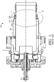
FIG. 1 is a cross section of a combustion system sealing arrangement of the prior art. -
FIG. 2 is a detailed cross section of a portion of the combustion system ofFIG. 1 . -
FIG. 3 is a cross section of a portion of an alternate combustion system sealing arrangement in accordance with the prior art. -
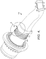
FIG. 4 is a perspective view of a combustion system not in accordance with the present invention. -
FIG. 5 is a detailed perspective view of a portion of the combustion system ofFIG. 4 . -
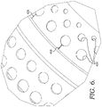
FIG. 6 is a further detailed perspective view of a portion of the combustion system ofFIG. 5 . -
FIG. 7 is a cross section view of a combustion system not in accordance with the present invention. -
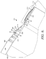
FIG. 8 is a detailed cross section of a portion of the combustion system ofFIG. 7 . -
FIG. 9 is a flow diagram depicting a method of regulating cooling fluid flow, not claimed herein. -
FIG. 10 is a cross section view of a portion of a combustion system in accordance with an embodiment of the present invention. -
FIG. 11 is a perspective view of a portion of the combustion system ofFIG. 10 . -
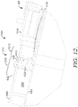
FIG. 12 is a cross section view of a portion of a combustion system in accordance with yet another alternate embodiment of the present invention. -
FIG. 13 is a perspective of a portion of the combustion system ofFIG. 12 . - The present invention discloses a system and method for regulating the flow of compressed air to a combustion system. Referring initially to
FIGS. 4-8 , asealing system 400 for use in a gas turbine combustor is shown. Thesealing system 400 comprises acombustion liner 402 positioned along a center axis A-A of agas turbine combustor 404 and also includes aflow sleeve 406 positioned radially outward of thecombustion liner 402, thereby forming anannular passage 408 between thecombustion liner 402 and theflow sleeve 406. Thesealing system 400 also comprises acompressible seal 410 positioned between thecombustion liner 402 and theflow sleeve 406. Thecompressible seal 410 is shown in more detail inFIGS. 5 ,6 , and8 , and has a firstannular portion 412, a secondannular portion 414, and atransition portion 416. As will be discussed in further detail below, thecompressible seal 410 regulates an airflow passing through theseal 410 and into theannular passage 408. - The
compressible seal 410 serves to regulate airflow passing therethrough for cooling ofcombustion liner 402 and then into thecombustion liner 402 for mixing with fuel. Thecompressible seal 410 provides a way of regulating the amount of cooling air permitted to pass into theannular passage 408 between theflow sleeve 406 andcombustion liner 402. In some prior art combustion systems, as shown inFIGS. 1-3 , there was no type of flow restriction device used to regulate the air flow. Instead, air flow was regulated by the overall opening or distance between the combustion liner and flow sleeve. Further, performance of a seal in prior art combustion systems was directly related to the roundness of the sealing interface. The compressible seal provides a more forgiving interface which accommodates out of round mating surfaces. - Referring back to
FIG. 8 , thecompressible seal 410 is fixedly secured to anannular ring 413 located proximate anaft end 418 of thecombustion liner 402 at the firstannular portion 412. The first diameter D1 of the firstannular portion 412 is sized to be slightly larger than the diameter of theannular ring 413 so as to slide into place over theannular ring 413 to facilitate it being secured to theannular ring 413. Thecompressible seal 410 is preferably secured to theannular ring 413 by a weld, such as a stitch weld or plug weld, or other acceptable weld type. Alternatively, thecompressible seal 410 may be brazed to theannular ring 413. - The
annular ring 413 is positioned about theaft end 418 of thecombustion liner 402 and forms acooling channel 420. The coolingchannel 420 is supplied with cooling air through one or more feed holes 422. Cooling air passes through the coolingchannel 420 and exits theaft end 418 of thecombustion liner 402. - As discussed above, and shown in
FIG. 8 , thecompressible seal 410 also comprises a secondannular portion 414 having a second diameter D2, where the secondannular portion 414 is located radially outward of the firstannular portion 412. The secondannular portion 414 is sized so as to interface with aninlet ring 424 of theflow sleeve 406. That is, theinlet ring 424 has an outer diameter OD and an inner diameter ID, where the second diameter D2 of the secondannular portion 414 is sized so as to be slightly larger than the inner diameter ID of theinlet ring 424 in its free condition so that the secondannular portion 414 of thecompressible seal 410 is under a compression fit with theinlet ring 424 of theflow sleeve 406 when thecompressible seal 410 is installed in theflow sleeve 406. As the secondannular portion 414 is compressed when engaged in theinlet ring 424 and thereby contacts and rubs against theinlet ring 424, to reduce the wear of the seal andinlet ring 424, a hardface coating can be applied to both the secondannular portion 414 and the ID portion of theinlet ring 424. - Referring to
FIGS. 5 ,6 , and8 , the secondannular portion 414 also comprises a plurality ofaxial slots 426 that extend to anaft end 411 of thecompressible seal 410, and for the embodiment depicted herein, also extend to thetransition portion 416. The plurality ofaxial slots 426 assist in permitting thecompressible seal 410 to compress upon installation in theinlet ring 424. In a representative embodiment of the present invention, eighteenaxial slots 426 each have a width of approximately 0.020 inches in a free state. However, as one skilled in the art understands, the exact number of slots and their respective free state width can vary. However, the width ofslot 426 needs to be wide enough to allow the seal to compress and seat inside theflow sleeve 406, but also be narrow enough to minimize leakage flow. - The
compressible seal 410 also comprises atransition portion 416 extending between the firstannular portion 412 and the secondannular portion 414. Thetransition portion 416 includes a way of regulating airflow passing through thecompressible seal 410. More specifically, thetransition portion 416 comprises a plurality ofopenings 428 positioned about thetransition portion 416. The plurality ofopenings 428 can be placed about thetransition portion 416 in a variety of ways. Such embodiments include an equal, uniform distribution ofopenings 428, arranging theopenings 428 into a plurality of rows, or a pre-determined pattern ofopenings 428 to distribute airflow in a pre-determined manner. For example, in an embodiment of the present invention, there are three rows of thirty-six holes in thetransition portion 416 along with two rows of holes in theflow sleeve 406, as shown inFIGS. 4-6 . This pattern provides air flow throughopenings 428 and the leakage air through theslots 426 in order to set the amount of airflow provided to thecombustion liner 402 to a desired level. Theopenings 428 are also arranged in a way so as to introduce air as soon as possible to cool thecombustion liner 402 while maintaining an acceptable chord length between theopenings 428. Furthermore, theopenings 428 are staggered to minimize crossflow effects and ultimately provide uniform flow to thecombustion liner 402, as cross flow effects can reduce the effectiveness of cooling air impinging on and cooling thecombustion liner 402. - Depending on the embodiment of the
compressible seal 410, the plurality ofaxial slots 426 may or may not intersect with the plurality of rows ofopenings 428. Theopenings 428 can be placed in thetransition portion 416 through a variety of manners such as punching, EDM, or laser cutting of thetransition portion 416. As one skilled in the art understands, the diameter of theopenings 428 will vary and is a function of the desired mass flow tocombustion liner 402, cooling requirements, and cross flow effects in theannular passage 408. - Depending on the exact fit-up of the
compressible seal 410 to the flowsleeve inlet ring 424, the effective area that remains open to permit air flow to pass therethrough can vary. For example, in a nominal fit-up embodiment of the present invention, the total amount of flow area open through the seal is about 0.55% of the total area. However, under a looser fit condition, such as either smaller seal diameter orlarger inlet ring 424 diameter, the amount of total flow area (leakage) through the compressible seal can approximately double to 1.11%. Thecompressible seal 410 is sized such that the secondannular portion 414 is preferably oversized by up to 0.020 inches in diameter in order to create an interference fit with the flowsleeve inlet ring 424. - The fit-up of the
compressible seal 410 also provides a thermally free structural support for the flow sleeve. Thecompressible seal 410 provides support that is capable of accommodating out of round mating surfaces without inducing constraint due to thermal growth. More specifically, the structural interaction between the compressible seal and the flow sleeve provides acoustical dampening by resisting the acoustical response of the hardware. - The
compressible seal 410 can be fabricated from a variety of materials and methods. For example, thecompressible seal 410 is generally fabricated from a single sheet of materials that is cut, rolled, welded and the formed to the desire diameter. Acceptable type seal materials include, but are not limited to, Inconel 718 and Hastelloy X, both nickel-based alloys. For the embodiment depicted, thecompressible seal 410 has a thickness of approximately 0.060 inches. However, the seal thickness can be changed to vary the amount of preload applied to theseal 410. Alternatively, other materials can be used, although these materials will have slightly less desirable material properties. The material chosen should have some flexibility or spring to it due to the required compression of theaxial slots 426. - Referring now to
FIG. 9 , amethod 900 of regulating cooling fluid flow to a gas turbine combustor is disclosed. Themethod 900 comprises the step 902 of providing a seal extending between a combustion liner and a flow sleeve, the seal having a plurality of openings in the seal. In thestep 904, a cooling fluid, such as air, is directed across the seal. In astep 906, a predetermined amount of air enters a passageway located between the combustion liner and the flow sleeve. Then in astep 908, a portion of the predetermined amount of air is directed to cool an aft end of the combustion liner. In astep 910, all remaining air, or other fluid, passes along an external passage of the combustion liner and is directed towards an inlet end of the combustion liner. - In operation, the compressed air discharges from an engine compressor and is directed into a plenum in which the one or
more combustion liners 402 and flowsleeves 406 are located. The compressed air is then drawn in to the combustion system through the plurality ofopenings 428 in thetransition portion 416. Theopenings 428 are sized to create a desired pressure drop and may be additionally sized to reduce thermal gradients along a combustion liner due to impingement effects on the liner surface. More specifically, for an embodiment of the present invention, the size of eachopening 428 is determined based on its relationship with theliner 402. The annulus of eachopening 428 is projected onto the surface of theliner 402 with respect to the opening centerline. The downstream surface area of this projection forms the general area available for the flow to exitopening 428. In order to minimize the flow variation due to manufacturing tolerances or misalignment of the liner with respect to the flow sleeve, and ultimately ensure theopening 428 controls the flow, this projection area is approximately 2.5 times the area of eachopening 428. - As discussed above, a portion of the compressed air is drawn downstream towards the
aft end 418 of thecombustion liner 402, into thepassageway 420 where it serves to cool the combustion liner aftend 418. However, a majority of the compressed air is directed upstream towards an inlet of thecombustion liner 402. This compressed air is directed between theflow sleeve 406 and thecombustion liner 402, through theannular passage 408. The compressed air cools the wall of thecombustion liner 402 as the air passes upstream towards the inlet end. To aid in enhancing the cooling effectiveness of the compressed air, thecombustion liner 402 may also include a plurality of heat transfer devices commonly referred to as trip strips. The heat transfer devices comprise a plurality of raised edges in the combustion liner wall, the raised edges extending into the flow of compressed air, so as to cause the flow to trip, thereby enhancing the heat transfer effectiveness of the compressed air. - In order to minimize the wear on the flow
sleeve inlet ring 424 and thecompressed seal 410, the secondannular portion 414 of thecompressible seal 410 and the inner diameter region of the flowsleeve inlet ring 424 can each have a wear reduction coating applied, such as a hardface coating. Therefore, any wear occurs to the coatings and not the components themselves. - An embodiment of the present invention is shown in
FIGS. 10 and11 . That is, in this embodiment of the present invention, asealing system 1000 for a gas turbine combustor is provided. Thesealing system 1000 comprises acombustion liner 1002, positioned along an axis (not shown) of the gas turbine combustor. Aflow sleeve 1004 is positioned radially outward of thecombustion liner 1002 forming anannular passage 1006 therebetween. - The
sealing system 1000 also comprises atransition duct 1008 having afirst wall 1010 and asecond wall 1012 located radially outward of thefirst wall 1010. Thetransition duct 1008 engages thecombustion liner 1002, where the aft end of thecombustion liner 1002 is slidably engaged in thefirst wall 1010 of thetransition duct 1008. Thesealing system 1000 also comprises acompressible seal 1014 having a firstannular portion 1016 and a secondannular portion 1018. Thecompressible seal 1014 is secured to theflow sleeve 1004 along the firstannular portion 1016. The means by which thecompressible seal 1014 is secured can include welding or brazing. For welding, thecompressible seal 1014 can be welded by resistance spot welds spaced about the perimeter of the seal, manual TIG welding, or other similar welding techniques. - As shown in
FIG. 10 , thesecond portion 1018 of thecompressible seal 1014 is in contact with thesecond wall 1012 of thetransition duct 1008. Thesecond portion 1018 has a curvedaft end 1020 where the curved shape helps to facilitate the engagement between thecompressible seal 1014 and thesecond wall 1012 of thetransition duct 1008. That is, the geometry of thesecond portion 1018 is sized such that the diameter of thesecond portion 1018 is slightly undersized compared to the diameter of the inlet ofsecond wall 1012. - Referring now to
FIGS. 10 and11 , thecompressible seal 1014 also comprises a plurality ofholes 1022. The plurality ofholes 1022 provides a means for regulating flow of cooling fluid through thecompressible seal 1014. The exact size and shape of the plurality ofhole 1022 can vary depending on the desired cooling flow through the seal. However, for an embodiment of the present invention, the plurality ofholes 1022 are circular in shape and range from approximately 0.100 to 0.500 inches in diameter. - As shown in
FIGS. 10 and11 , in an embodiment of the present invention, thecompressible seal 1014 further comprises a plurality ofaxial slots 1024. Theaxial slots 1024 extend from the aft end of thecompressible seal 1014 forward to the plurality ofholes 1022 and intersect theholes 1022. As shown inFIG. 10 , the secondannular portion 1018 comprises a curvedaft end 1020 and atransition portion 1026. As discussed above, thetransition portion 1026 and the curvedaft end 1020 are sized and configured so as to ensure a constant pressure applied to thesecond wall 1012 of thetransition duct 1008. - The plurality of
holes 1022 andaxial slots 1024 provide a way of directing cooling fluid, such as compressed air, to thepassageway 1006. Theholes 1022 are sized so as to supply a majority of the cooling fluid to thepassageway 1006. However, the plurality ofaxial slots 1024 can also provide some cooling fluid depending on their final size when theflow sleeve 1004 is secured to thesecond wall 1012 of thetransition duct 1008. - Alternatively, the
compressible seal 1014 may be oriented in an opposing direction, as shown inFIGS. 12 and13 . More specifically, theseal 1014 includes the same general features of the compressible seal shown inFIGS. 10 and11 , however, thecompressible seal 1014 ofFIGS. 12 and13 is oriented opposite to that of the configuration inFIGS. 10 and11 . More specifically, the firstannular portion 1016 is secured to the outer surface of thesecond wall 1012 of thetransition duct 1008. Thecompressible seal 1014 then extends forward towards theflow sleeve 1004 where asecond portion 1018 of thecompressible seal 1014 contacts the flow sleeve wall proximate the curvedaft end 1020. Thecompressible seal 1014 is secured to thesecond wall 1012 of thetransition duct 1008 by a means such as brazing or welding. - While the invention has been described in what is known as presently the preferred embodiment, it is to be understood that the invention is not to be limited to the disclosed embodiment but, on the contrary, is intended to cover various modifications and equivalent arrangements within the scope of the following claims. The present invention has been described in relation to particular embodiments, which are intended in all respects to be illustrative rather than restrictive.
- From the foregoing, it will be seen that this invention is one well adapted to attain all the ends and objects set forth above, together with other advantages which are obvious and inherent to the system and method. It will be understood that certain features and sub-combinations are of utility and may be employed without reference to other features and sub-combinations. This is contemplated by and within the scope of the claims.
Claims (5)
- A sealing system (1000) for a gas turbine combustor , said system (1000) comprising: a combustion liner (1002) positioned along an axis of the gas turbine combustor; a flow sleeve (1004) positioned radially outward of the combustion liner (1002) and forming an annular passage (1006) between the combustion liner (1002) and the flow sleeve (1004); a transition duct (1008) having a first wall (1010) and a second wall (1012), where the second wall (1012) is located radially outward of the first wall (1010), the first wall (1010) engaged with the combustion liner (1002); characterized by a compressible seal (1014) having either a first annular portion (1016) secured to the flow sleeve (1004) and a second annular portion (1018) in contact with the second wall (1012) of the transition duct (1008), or a first annular portion (1016) secured to the second wall of the transition duct (1008) and a second annular portion (1018) in contact with the flow sleeve (1004); wherein the second annular portion (1018) has a curved aft end (1020).
- The sealing system of claim 1 further comprising a plurality of holes (1022) for regulating flow of cooling fluid through the compressible seal (1014).
- The sealing system of claim 2 further comprising a plurality of axial slots (1024) extending from the aft end (1020) of the compressible seal (1014).
- The sealing system of claim 3, wherein the plurality of axial slots (1024) intersect the plurality of holes (1022).
- The sealing system of claim 4, wherein the plurality of axial slots (1024) and plurality of holes (1022) regulate the flow of compressed air into the annular passage (1006).
Applications Claiming Priority (2)
| Application Number | Priority Date | Filing Date | Title |
|---|---|---|---|
| US14/512,633 US10215418B2 (en) | 2014-10-13 | 2014-10-13 | Sealing device for a gas turbine combustor |
| PCT/US2015/055331 WO2016061101A1 (en) | 2014-10-13 | 2015-10-13 | Sealing device for a gas turbine combustor |
Publications (3)
| Publication Number | Publication Date |
|---|---|
| EP3207313A1 EP3207313A1 (en) | 2017-08-23 |
| EP3207313A4 EP3207313A4 (en) | 2018-08-15 |
| EP3207313B1 true EP3207313B1 (en) | 2022-05-04 |
Family
ID=55655192
Family Applications (1)
| Application Number | Title | Priority Date | Filing Date |
|---|---|---|---|
| EP15850671.7A Not-in-force EP3207313B1 (en) | 2014-10-13 | 2015-10-13 | Sealing device for a gas turbine combustor |
Country Status (5)
| Country | Link |
|---|---|
| US (1) | US10215418B2 (en) |
| EP (1) | EP3207313B1 (en) |
| JP (1) | JP6703530B2 (en) |
| CN (1) | CN107429919B (en) |
| WO (1) | WO2016061101A1 (en) |
Families Citing this family (7)
| Publication number | Priority date | Publication date | Assignee | Title |
|---|---|---|---|---|
| WO2017192147A1 (en) * | 2016-05-06 | 2017-11-09 | Siemens Aktiengesellschaft | Flow metering device for gas turbine engine |
| FR3061761B1 (en) * | 2017-01-10 | 2021-01-01 | Safran Aircraft Engines | TURBOMACHINE COMBUSTION CHAMBER |
| KR101986729B1 (en) * | 2017-08-22 | 2019-06-07 | 두산중공업 주식회사 | Cooling passage for concentrated cooling of seal area and a gas turbine combustor using the same |
| KR102038112B1 (en) * | 2017-10-13 | 2019-10-29 | 두산중공업 주식회사 | Combustor and gas turbine including the same |
| KR102050563B1 (en) * | 2017-11-03 | 2019-11-29 | 두산중공업 주식회사 | Combustor and gas turbine comprising the same |
| KR102377720B1 (en) * | 2019-04-10 | 2022-03-23 | 두산중공업 주식회사 | Liner cooling structure with improved pressure losses and combustor for gas turbine having the same |
| US11371699B2 (en) * | 2019-11-12 | 2022-06-28 | General Electric Company | Integrated front panel for a burner |
Family Cites Families (31)
| Publication number | Priority date | Publication date | Assignee | Title |
|---|---|---|---|---|
| SE413431B (en) * | 1978-08-30 | 1980-05-27 | Volvo Flygmotor Ab | Aggregate for combustion of non-explosive process gases |
| US4413477A (en) * | 1980-12-29 | 1983-11-08 | General Electric Company | Liner assembly for gas turbine combustor |
| US4413470A (en) * | 1981-03-05 | 1983-11-08 | Electric Power Research Institute, Inc. | Catalytic combustion system for a stationary combustion turbine having a transition duct mounted catalytic element |
| JPH08284688A (en) * | 1995-04-18 | 1996-10-29 | Hitachi Ltd | Gas turbine and gas turbine combustion device |
| JPH09195799A (en) | 1996-01-17 | 1997-07-29 | Mitsubishi Heavy Ind Ltd | Spring seal apparatus for combustor |
| JP3478531B2 (en) * | 2000-04-21 | 2003-12-15 | 川崎重工業株式会社 | Gas turbine ceramic component support structure |
| ITMI20031673A1 (en) * | 2003-08-28 | 2005-02-28 | Nuovo Pignone Spa | FIXING SYSTEM OF A FLAME TUBE OR "LINER". |
| US7096668B2 (en) * | 2003-12-22 | 2006-08-29 | Martling Vincent C | Cooling and sealing design for a gas turbine combustion system |
| US7269957B2 (en) | 2004-05-28 | 2007-09-18 | Martling Vincent C | Combustion liner having improved cooling and sealing |
| US7377116B2 (en) * | 2005-04-28 | 2008-05-27 | Siemens Power Generation, Inc. | Gas turbine combustor barrier structures for spring clips |
| US7707835B2 (en) | 2005-06-15 | 2010-05-04 | General Electric Company | Axial flow sleeve for a turbine combustor and methods of introducing flow sleeve air |
| US7421842B2 (en) * | 2005-07-18 | 2008-09-09 | Siemens Power Generation, Inc. | Turbine spring clip seal |
| US7805946B2 (en) * | 2005-12-08 | 2010-10-05 | Siemens Energy, Inc. | Combustor flow sleeve attachment system |
| US8109098B2 (en) * | 2006-05-04 | 2012-02-07 | Siemens Energy, Inc. | Combustor liner for gas turbine engine |
| US7524167B2 (en) * | 2006-05-04 | 2009-04-28 | Siemens Energy, Inc. | Combustor spring clip seal system |
| US7802431B2 (en) * | 2006-07-27 | 2010-09-28 | Siemens Energy, Inc. | Combustor liner with reverse flow for gas turbine engine |
| FR2905166B1 (en) * | 2006-08-28 | 2008-11-14 | Snecma Sa | ANNULAR COMBUSTION CHAMBER OF A TURBOMACHINE. |
| FR2914707B1 (en) * | 2007-04-05 | 2009-10-30 | Snecma Propulsion Solide Sa | ASSEMBLY METHOD WITH RECOVERY OF TWO PIECES HAVING DIFFERENT EXPANSION COEFFICIENTS AND ASSEMBLY SO OBTAINED |
| US8245514B2 (en) * | 2008-07-10 | 2012-08-21 | United Technologies Corporation | Combustion liner for a gas turbine engine including heat transfer columns to increase cooling of a hula seal at the transition duct region |
| US8490400B2 (en) * | 2008-09-15 | 2013-07-23 | Siemens Energy, Inc. | Combustor assembly comprising a combustor device, a transition duct and a flow conditioner |
| US8307657B2 (en) | 2009-03-10 | 2012-11-13 | General Electric Company | Combustor liner cooling system |
| US8511089B2 (en) * | 2009-07-31 | 2013-08-20 | Rolls-Royce Corporation | Relief slot for combustion liner |
| US8516822B2 (en) | 2010-03-02 | 2013-08-27 | General Electric Company | Angled vanes in combustor flow sleeve |
| US8359867B2 (en) * | 2010-04-08 | 2013-01-29 | General Electric Company | Combustor having a flow sleeve |
| US8276391B2 (en) * | 2010-04-19 | 2012-10-02 | General Electric Company | Combustor liner cooling at transition duct interface and related method |
| US8499566B2 (en) * | 2010-08-12 | 2013-08-06 | General Electric Company | Combustor liner cooling system |
| US20120304657A1 (en) * | 2011-06-06 | 2012-12-06 | General Electric Company | Lock leaf hula seal |
| US9347330B2 (en) | 2012-12-29 | 2016-05-24 | United Technologies Corporation | Finger seal |
| US9163837B2 (en) * | 2013-02-27 | 2015-10-20 | Siemens Aktiengesellschaft | Flow conditioner in a combustor of a gas turbine engine |
| JP6118596B2 (en) * | 2013-03-15 | 2017-04-19 | 三菱日立パワーシステムズ株式会社 | Elastic ring, combustor and gas turbine equipped with the same, and method for producing elastic ring |
| US9879556B2 (en) * | 2014-04-11 | 2018-01-30 | United Technologies Corporation | Cooled finger seal |
-
2014
- 2014-10-13 US US14/512,633 patent/US10215418B2/en active Active
-
2015
- 2015-10-13 WO PCT/US2015/055331 patent/WO2016061101A1/en not_active Ceased
- 2015-10-13 EP EP15850671.7A patent/EP3207313B1/en not_active Not-in-force
- 2015-10-13 JP JP2017519823A patent/JP6703530B2/en active Active
- 2015-10-13 CN CN201580055725.3A patent/CN107429919B/en active Active
Also Published As
| Publication number | Publication date |
|---|---|
| JP6703530B2 (en) | 2020-06-03 |
| CN107429919B (en) | 2020-03-17 |
| EP3207313A4 (en) | 2018-08-15 |
| WO2016061101A1 (en) | 2016-04-21 |
| US20160102864A1 (en) | 2016-04-14 |
| US10215418B2 (en) | 2019-02-26 |
| JP2017533400A (en) | 2017-11-09 |
| EP3207313A1 (en) | 2017-08-23 |
| CN107429919A (en) | 2017-12-01 |
Similar Documents
| Publication | Publication Date | Title |
|---|---|---|
| US10215418B2 (en) | Sealing device for a gas turbine combustor | |
| EP3537048B1 (en) | A lean burn fuel injector | |
| US11002190B2 (en) | Segmented annular combustion system | |
| US20100071377A1 (en) | Combustor Apparatus for Use in a Gas Turbine Engine | |
| US8516820B2 (en) | Integral flow sleeve and fuel injector assembly | |
| US11747018B2 (en) | Combustor with dilution openings | |
| US9631816B2 (en) | Bundled tube fuel nozzle | |
| US8528340B2 (en) | Turbine engine flow sleeve | |
| US7310952B2 (en) | Methods and apparatus for attaching swirlers to gas turbine engine combustors | |
| US20100018210A1 (en) | Combustor apparatus in a gas turbine engine | |
| US9151171B2 (en) | Stepped inlet ring for a transition downstream from combustor basket in a combustion turbine engine | |
| EP2947390B1 (en) | A combustion chamber arrangement | |
| US20170268783A1 (en) | Axially staged fuel injector assembly mounting | |
| JP2016099107A (en) | Premixed fuel nozzle assembly | |
| KR100970124B1 (en) | Catalytic Oxidation Module for Gas Turbine Engines | |
| US10677466B2 (en) | Combustor inlet flow conditioner | |
| US20160281979A1 (en) | Fuel nozzle with hemispherical dome air inlet | |
| JPH08284688A (en) | Gas turbine and gas turbine combustion device | |
| US9038393B2 (en) | Fuel gas cooling system for combustion basket spring clip seal support | |
| US20180163968A1 (en) | Fuel Nozzle Assembly with Inlet Flow Conditioner | |
| US20120085099A1 (en) | Tunable seal in a gas turbine engine | |
| DE102007034737A1 (en) | Fuel inflow controlling device for gas-turbine engine combustor, has control system actively controlling fuel inflow, which is supplied to mixers of mixing device by using nozzle and activating valves based on signals received by sensor | |
| US20140208756A1 (en) | System For Reducing Combustion Noise And Improving Cooling | |
| EP4202301B1 (en) | Combustor with dilution openings | |
| US20230296250A1 (en) | Turbine engine combustor and combustor liner |
Legal Events
| Date | Code | Title | Description |
|---|---|---|---|
| STAA | Information on the status of an ep patent application or granted ep patent |
Free format text: STATUS: THE INTERNATIONAL PUBLICATION HAS BEEN MADE |
|
| PUAI | Public reference made under article 153(3) epc to a published international application that has entered the european phase |
Free format text: ORIGINAL CODE: 0009012 |
|
| STAA | Information on the status of an ep patent application or granted ep patent |
Free format text: STATUS: REQUEST FOR EXAMINATION WAS MADE |
|
| 17P | Request for examination filed |
Effective date: 20170424 |
|
| AK | Designated contracting states |
Kind code of ref document: A1 Designated state(s): AL AT BE BG CH CY CZ DE DK EE ES FI FR GB GR HR HU IE IS IT LI LT LU LV MC MK MT NL NO PL PT RO RS SE SI SK SM TR |
|
| AX | Request for extension of the european patent |
Extension state: BA ME |
|
| DAV | Request for validation of the european patent (deleted) | ||
| DAX | Request for extension of the european patent (deleted) | ||
| A4 | Supplementary search report drawn up and despatched |
Effective date: 20180713 |
|
| RIC1 | Information provided on ipc code assigned before grant |
Ipc: F01D 9/02 20060101ALI20180709BHEP Ipc: F23R 3/46 20060101ALI20180709BHEP Ipc: F23R 3/42 20060101AFI20180709BHEP Ipc: F23R 3/60 20060101ALI20180709BHEP |
|
| STAA | Information on the status of an ep patent application or granted ep patent |
Free format text: STATUS: EXAMINATION IS IN PROGRESS |
|
| RAP1 | Party data changed (applicant data changed or rights of an application transferred) |
Owner name: ANSALDO ENERGIA IP UK LIMITED |
|
| 17Q | First examination report despatched |
Effective date: 20200226 |
|
| RAP1 | Party data changed (applicant data changed or rights of an application transferred) |
Owner name: H2 IP UK LIMITED |
|
| GRAP | Despatch of communication of intention to grant a patent |
Free format text: ORIGINAL CODE: EPIDOSNIGR1 |
|
| STAA | Information on the status of an ep patent application or granted ep patent |
Free format text: STATUS: GRANT OF PATENT IS INTENDED |
|
| INTG | Intention to grant announced |
Effective date: 20211123 |
|
| RIN1 | Information on inventor provided before grant (corrected) |
Inventor name: KESHAVA-BHATTU, RAMESH Inventor name: GIEL, DAVID Inventor name: JORGENSEN, STEPHEN W. Inventor name: METTERNICH, JEREMY |
|
| GRAS | Grant fee paid |
Free format text: ORIGINAL CODE: EPIDOSNIGR3 |
|
| GRAA | (expected) grant |
Free format text: ORIGINAL CODE: 0009210 |
|
| STAA | Information on the status of an ep patent application or granted ep patent |
Free format text: STATUS: THE PATENT HAS BEEN GRANTED |
|
| AK | Designated contracting states |
Kind code of ref document: B1 Designated state(s): AL AT BE BG CH CY CZ DE DK EE ES FI FR GB GR HR HU IE IS IT LI LT LU LV MC MK MT NL NO PL PT RO RS SE SI SK SM TR |
|
| REG | Reference to a national code |
Ref country code: GB Ref legal event code: FG4D |
|
| REG | Reference to a national code |
Ref country code: CH Ref legal event code: EP |
|
| REG | Reference to a national code |
Ref country code: AT Ref legal event code: REF Ref document number: 1489432 Country of ref document: AT Kind code of ref document: T Effective date: 20220515 |
|
| REG | Reference to a national code |
Ref country code: DE Ref legal event code: R096 Ref document number: 602015078777 Country of ref document: DE |
|
| REG | Reference to a national code |
Ref country code: IE Ref legal event code: FG4D |
|
| REG | Reference to a national code |
Ref country code: NL Ref legal event code: FP |
|
| REG | Reference to a national code |
Ref country code: LT Ref legal event code: MG9D |
|
| REG | Reference to a national code |
Ref country code: AT Ref legal event code: MK05 Ref document number: 1489432 Country of ref document: AT Kind code of ref document: T Effective date: 20220504 |
|
| PG25 | Lapsed in a contracting state [announced via postgrant information from national office to epo] |
Ref country code: SE Free format text: LAPSE BECAUSE OF FAILURE TO SUBMIT A TRANSLATION OF THE DESCRIPTION OR TO PAY THE FEE WITHIN THE PRESCRIBED TIME-LIMIT Effective date: 20220504 Ref country code: PT Free format text: LAPSE BECAUSE OF FAILURE TO SUBMIT A TRANSLATION OF THE DESCRIPTION OR TO PAY THE FEE WITHIN THE PRESCRIBED TIME-LIMIT Effective date: 20220905 Ref country code: NO Free format text: LAPSE BECAUSE OF FAILURE TO SUBMIT A TRANSLATION OF THE DESCRIPTION OR TO PAY THE FEE WITHIN THE PRESCRIBED TIME-LIMIT Effective date: 20220804 Ref country code: LT Free format text: LAPSE BECAUSE OF FAILURE TO SUBMIT A TRANSLATION OF THE DESCRIPTION OR TO PAY THE FEE WITHIN THE PRESCRIBED TIME-LIMIT Effective date: 20220504 Ref country code: HR Free format text: LAPSE BECAUSE OF FAILURE TO SUBMIT A TRANSLATION OF THE DESCRIPTION OR TO PAY THE FEE WITHIN THE PRESCRIBED TIME-LIMIT Effective date: 20220504 Ref country code: GR Free format text: LAPSE BECAUSE OF FAILURE TO SUBMIT A TRANSLATION OF THE DESCRIPTION OR TO PAY THE FEE WITHIN THE PRESCRIBED TIME-LIMIT Effective date: 20220805 Ref country code: FI Free format text: LAPSE BECAUSE OF FAILURE TO SUBMIT A TRANSLATION OF THE DESCRIPTION OR TO PAY THE FEE WITHIN THE PRESCRIBED TIME-LIMIT Effective date: 20220504 Ref country code: BG Free format text: LAPSE BECAUSE OF FAILURE TO SUBMIT A TRANSLATION OF THE DESCRIPTION OR TO PAY THE FEE WITHIN THE PRESCRIBED TIME-LIMIT Effective date: 20220804 Ref country code: AT Free format text: LAPSE BECAUSE OF FAILURE TO SUBMIT A TRANSLATION OF THE DESCRIPTION OR TO PAY THE FEE WITHIN THE PRESCRIBED TIME-LIMIT Effective date: 20220504 |
|
| PG25 | Lapsed in a contracting state [announced via postgrant information from national office to epo] |
Ref country code: RS Free format text: LAPSE BECAUSE OF FAILURE TO SUBMIT A TRANSLATION OF THE DESCRIPTION OR TO PAY THE FEE WITHIN THE PRESCRIBED TIME-LIMIT Effective date: 20220504 Ref country code: PL Free format text: LAPSE BECAUSE OF FAILURE TO SUBMIT A TRANSLATION OF THE DESCRIPTION OR TO PAY THE FEE WITHIN THE PRESCRIBED TIME-LIMIT Effective date: 20220504 Ref country code: LV Free format text: LAPSE BECAUSE OF FAILURE TO SUBMIT A TRANSLATION OF THE DESCRIPTION OR TO PAY THE FEE WITHIN THE PRESCRIBED TIME-LIMIT Effective date: 20220504 Ref country code: IS Free format text: LAPSE BECAUSE OF FAILURE TO SUBMIT A TRANSLATION OF THE DESCRIPTION OR TO PAY THE FEE WITHIN THE PRESCRIBED TIME-LIMIT Effective date: 20220904 |
|
| PG25 | Lapsed in a contracting state [announced via postgrant information from national office to epo] |
Ref country code: SM Free format text: LAPSE BECAUSE OF FAILURE TO SUBMIT A TRANSLATION OF THE DESCRIPTION OR TO PAY THE FEE WITHIN THE PRESCRIBED TIME-LIMIT Effective date: 20220504 Ref country code: SK Free format text: LAPSE BECAUSE OF FAILURE TO SUBMIT A TRANSLATION OF THE DESCRIPTION OR TO PAY THE FEE WITHIN THE PRESCRIBED TIME-LIMIT Effective date: 20220504 Ref country code: RO Free format text: LAPSE BECAUSE OF FAILURE TO SUBMIT A TRANSLATION OF THE DESCRIPTION OR TO PAY THE FEE WITHIN THE PRESCRIBED TIME-LIMIT Effective date: 20220504 Ref country code: ES Free format text: LAPSE BECAUSE OF FAILURE TO SUBMIT A TRANSLATION OF THE DESCRIPTION OR TO PAY THE FEE WITHIN THE PRESCRIBED TIME-LIMIT Effective date: 20220504 Ref country code: EE Free format text: LAPSE BECAUSE OF FAILURE TO SUBMIT A TRANSLATION OF THE DESCRIPTION OR TO PAY THE FEE WITHIN THE PRESCRIBED TIME-LIMIT Effective date: 20220504 Ref country code: DK Free format text: LAPSE BECAUSE OF FAILURE TO SUBMIT A TRANSLATION OF THE DESCRIPTION OR TO PAY THE FEE WITHIN THE PRESCRIBED TIME-LIMIT Effective date: 20220504 Ref country code: CZ Free format text: LAPSE BECAUSE OF FAILURE TO SUBMIT A TRANSLATION OF THE DESCRIPTION OR TO PAY THE FEE WITHIN THE PRESCRIBED TIME-LIMIT Effective date: 20220504 |
|
| REG | Reference to a national code |
Ref country code: DE Ref legal event code: R097 Ref document number: 602015078777 Country of ref document: DE |
|
| PLBE | No opposition filed within time limit |
Free format text: ORIGINAL CODE: 0009261 |
|
| STAA | Information on the status of an ep patent application or granted ep patent |
Free format text: STATUS: NO OPPOSITION FILED WITHIN TIME LIMIT |
|
| PG25 | Lapsed in a contracting state [announced via postgrant information from national office to epo] |
Ref country code: AL Free format text: LAPSE BECAUSE OF FAILURE TO SUBMIT A TRANSLATION OF THE DESCRIPTION OR TO PAY THE FEE WITHIN THE PRESCRIBED TIME-LIMIT Effective date: 20220504 |
|
| 26N | No opposition filed |
Effective date: 20230207 |
|
| REG | Reference to a national code |
Ref country code: DE Ref legal event code: R119 Ref document number: 602015078777 Country of ref document: DE |
|
| PG25 | Lapsed in a contracting state [announced via postgrant information from national office to epo] |
Ref country code: SI Free format text: LAPSE BECAUSE OF FAILURE TO SUBMIT A TRANSLATION OF THE DESCRIPTION OR TO PAY THE FEE WITHIN THE PRESCRIBED TIME-LIMIT Effective date: 20220504 Ref country code: MC Free format text: LAPSE BECAUSE OF FAILURE TO SUBMIT A TRANSLATION OF THE DESCRIPTION OR TO PAY THE FEE WITHIN THE PRESCRIBED TIME-LIMIT Effective date: 20220504 |
|
| REG | Reference to a national code |
Ref country code: CH Ref legal event code: PL |
|
| REG | Reference to a national code |
Ref country code: NL Ref legal event code: MM Effective date: 20221101 |
|
| REG | Reference to a national code |
Ref country code: BE Ref legal event code: MM Effective date: 20221031 |
|
| GBPC | Gb: european patent ceased through non-payment of renewal fee |
Effective date: 20221013 |
|
| PG25 | Lapsed in a contracting state [announced via postgrant information from national office to epo] |
Ref country code: LU Free format text: LAPSE BECAUSE OF NON-PAYMENT OF DUE FEES Effective date: 20221013 |
|
| PG25 | Lapsed in a contracting state [announced via postgrant information from national office to epo] |
Ref country code: NL Free format text: LAPSE BECAUSE OF NON-PAYMENT OF DUE FEES Effective date: 20221101 Ref country code: LI Free format text: LAPSE BECAUSE OF NON-PAYMENT OF DUE FEES Effective date: 20221031 Ref country code: FR Free format text: LAPSE BECAUSE OF NON-PAYMENT OF DUE FEES Effective date: 20221031 Ref country code: DE Free format text: LAPSE BECAUSE OF NON-PAYMENT OF DUE FEES Effective date: 20230503 Ref country code: CH Free format text: LAPSE BECAUSE OF NON-PAYMENT OF DUE FEES Effective date: 20221031 |
|
| PG25 | Lapsed in a contracting state [announced via postgrant information from national office to epo] |
Ref country code: BE Free format text: LAPSE BECAUSE OF NON-PAYMENT OF DUE FEES Effective date: 20221031 |
|
| PG25 | Lapsed in a contracting state [announced via postgrant information from national office to epo] |
Ref country code: IT Free format text: LAPSE BECAUSE OF NON-PAYMENT OF DUE FEES Effective date: 20221013 Ref country code: IE Free format text: LAPSE BECAUSE OF NON-PAYMENT OF DUE FEES Effective date: 20221013 Ref country code: GB Free format text: LAPSE BECAUSE OF NON-PAYMENT OF DUE FEES Effective date: 20221013 |
|
| PG25 | Lapsed in a contracting state [announced via postgrant information from national office to epo] |
Ref country code: HU Free format text: LAPSE BECAUSE OF FAILURE TO SUBMIT A TRANSLATION OF THE DESCRIPTION OR TO PAY THE FEE WITHIN THE PRESCRIBED TIME-LIMIT; INVALID AB INITIO Effective date: 20151013 |
|
| PG25 | Lapsed in a contracting state [announced via postgrant information from national office to epo] |
Ref country code: CY Free format text: LAPSE BECAUSE OF FAILURE TO SUBMIT A TRANSLATION OF THE DESCRIPTION OR TO PAY THE FEE WITHIN THE PRESCRIBED TIME-LIMIT Effective date: 20220504 |
|
| PG25 | Lapsed in a contracting state [announced via postgrant information from national office to epo] |
Ref country code: MK Free format text: LAPSE BECAUSE OF FAILURE TO SUBMIT A TRANSLATION OF THE DESCRIPTION OR TO PAY THE FEE WITHIN THE PRESCRIBED TIME-LIMIT Effective date: 20220504 |
|
| PG25 | Lapsed in a contracting state [announced via postgrant information from national office to epo] |
Ref country code: TR Free format text: LAPSE BECAUSE OF FAILURE TO SUBMIT A TRANSLATION OF THE DESCRIPTION OR TO PAY THE FEE WITHIN THE PRESCRIBED TIME-LIMIT Effective date: 20220504 |
|
| PG25 | Lapsed in a contracting state [announced via postgrant information from national office to epo] |
Ref country code: MT Free format text: LAPSE BECAUSE OF FAILURE TO SUBMIT A TRANSLATION OF THE DESCRIPTION OR TO PAY THE FEE WITHIN THE PRESCRIBED TIME-LIMIT Effective date: 20220504 |
|
| PG25 | Lapsed in a contracting state [announced via postgrant information from national office to epo] |
Ref country code: BG Free format text: LAPSE BECAUSE OF FAILURE TO SUBMIT A TRANSLATION OF THE DESCRIPTION OR TO PAY THE FEE WITHIN THE PRESCRIBED TIME-LIMIT Effective date: 20220504 |
|
| PG25 | Lapsed in a contracting state [announced via postgrant information from national office to epo] |
Ref country code: BG Free format text: LAPSE BECAUSE OF FAILURE TO SUBMIT A TRANSLATION OF THE DESCRIPTION OR TO PAY THE FEE WITHIN THE PRESCRIBED TIME-LIMIT Effective date: 20220504 |