EP3207287B1 - Fiber reinforced plenum for limited-slip differential - Google Patents
Fiber reinforced plenum for limited-slip differential Download PDFInfo
- Publication number
- EP3207287B1 EP3207287B1 EP15851381.2A EP15851381A EP3207287B1 EP 3207287 B1 EP3207287 B1 EP 3207287B1 EP 15851381 A EP15851381 A EP 15851381A EP 3207287 B1 EP3207287 B1 EP 3207287B1
- Authority
- EP
- European Patent Office
- Prior art keywords
- housing body
- plenum housing
- plenum
- differential
- differential assembly
- Prior art date
- Legal status (The legal status is an assumption and is not a legal conclusion. Google has not performed a legal analysis and makes no representation as to the accuracy of the status listed.)
- Active
Links
Images



Classifications
-
- F—MECHANICAL ENGINEERING; LIGHTING; HEATING; WEAPONS; BLASTING
- F16—ENGINEERING ELEMENTS AND UNITS; GENERAL MEASURES FOR PRODUCING AND MAINTAINING EFFECTIVE FUNCTIONING OF MACHINES OR INSTALLATIONS; THERMAL INSULATION IN GENERAL
- F16H—GEARING
- F16H48/00—Differential gearings
- F16H48/38—Constructional details
- F16H48/40—Constructional details characterised by features of the rotating cases
-
- B—PERFORMING OPERATIONS; TRANSPORTING
- B29—WORKING OF PLASTICS; WORKING OF SUBSTANCES IN A PLASTIC STATE IN GENERAL
- B29C—SHAPING OR JOINING OF PLASTICS; SHAPING OF MATERIAL IN A PLASTIC STATE, NOT OTHERWISE PROVIDED FOR; AFTER-TREATMENT OF THE SHAPED PRODUCTS, e.g. REPAIRING
- B29C45/00—Injection moulding, i.e. forcing the required volume of moulding material through a nozzle into a closed mould; Apparatus therefor
- B29C45/0005—Injection moulding, i.e. forcing the required volume of moulding material through a nozzle into a closed mould; Apparatus therefor using fibre reinforcements
-
- B—PERFORMING OPERATIONS; TRANSPORTING
- B29—WORKING OF PLASTICS; WORKING OF SUBSTANCES IN A PLASTIC STATE IN GENERAL
- B29C—SHAPING OR JOINING OF PLASTICS; SHAPING OF MATERIAL IN A PLASTIC STATE, NOT OTHERWISE PROVIDED FOR; AFTER-TREATMENT OF THE SHAPED PRODUCTS, e.g. REPAIRING
- B29C45/00—Injection moulding, i.e. forcing the required volume of moulding material through a nozzle into a closed mould; Apparatus therefor
- B29C45/0025—Preventing defects on the moulded article, e.g. weld lines, shrinkage marks
-
- B—PERFORMING OPERATIONS; TRANSPORTING
- B29—WORKING OF PLASTICS; WORKING OF SUBSTANCES IN A PLASTIC STATE IN GENERAL
- B29C—SHAPING OR JOINING OF PLASTICS; SHAPING OF MATERIAL IN A PLASTIC STATE, NOT OTHERWISE PROVIDED FOR; AFTER-TREATMENT OF THE SHAPED PRODUCTS, e.g. REPAIRING
- B29C45/00—Injection moulding, i.e. forcing the required volume of moulding material through a nozzle into a closed mould; Apparatus therefor
- B29C45/17—Component parts, details or accessories; Auxiliary operations
- B29C45/20—Injection nozzles
- B29C45/22—Multiple nozzle systems
-
- B—PERFORMING OPERATIONS; TRANSPORTING
- B29—WORKING OF PLASTICS; WORKING OF SUBSTANCES IN A PLASTIC STATE IN GENERAL
- B29C—SHAPING OR JOINING OF PLASTICS; SHAPING OF MATERIAL IN A PLASTIC STATE, NOT OTHERWISE PROVIDED FOR; AFTER-TREATMENT OF THE SHAPED PRODUCTS, e.g. REPAIRING
- B29C45/00—Injection moulding, i.e. forcing the required volume of moulding material through a nozzle into a closed mould; Apparatus therefor
- B29C45/17—Component parts, details or accessories; Auxiliary operations
- B29C45/20—Injection nozzles
- B29C45/23—Feed stopping equipment
- B29C45/234—Valves opened by the pressure of the moulding material
-
- F—MECHANICAL ENGINEERING; LIGHTING; HEATING; WEAPONS; BLASTING
- F16—ENGINEERING ELEMENTS AND UNITS; GENERAL MEASURES FOR PRODUCING AND MAINTAINING EFFECTIVE FUNCTIONING OF MACHINES OR INSTALLATIONS; THERMAL INSULATION IN GENERAL
- F16H—GEARING
- F16H48/00—Differential gearings
- F16H48/20—Arrangements for suppressing or influencing the differential action, e.g. locking devices
- F16H48/27—Arrangements for suppressing or influencing the differential action, e.g. locking devices using internally-actuatable fluid pressure, e.g. internal pump types
-
- F—MECHANICAL ENGINEERING; LIGHTING; HEATING; WEAPONS; BLASTING
- F16—ENGINEERING ELEMENTS AND UNITS; GENERAL MEASURES FOR PRODUCING AND MAINTAINING EFFECTIVE FUNCTIONING OF MACHINES OR INSTALLATIONS; THERMAL INSULATION IN GENERAL
- F16H—GEARING
- F16H48/00—Differential gearings
- F16H48/38—Constructional details
-
- B—PERFORMING OPERATIONS; TRANSPORTING
- B29—WORKING OF PLASTICS; WORKING OF SUBSTANCES IN A PLASTIC STATE IN GENERAL
- B29C—SHAPING OR JOINING OF PLASTICS; SHAPING OF MATERIAL IN A PLASTIC STATE, NOT OTHERWISE PROVIDED FOR; AFTER-TREATMENT OF THE SHAPED PRODUCTS, e.g. REPAIRING
- B29C45/00—Injection moulding, i.e. forcing the required volume of moulding material through a nozzle into a closed mould; Apparatus therefor
- B29C45/0025—Preventing defects on the moulded article, e.g. weld lines, shrinkage marks
- B29C2045/0027—Gate or gate mark locations
-
- B—PERFORMING OPERATIONS; TRANSPORTING
- B29—WORKING OF PLASTICS; WORKING OF SUBSTANCES IN A PLASTIC STATE IN GENERAL
- B29C—SHAPING OR JOINING OF PLASTICS; SHAPING OF MATERIAL IN A PLASTIC STATE, NOT OTHERWISE PROVIDED FOR; AFTER-TREATMENT OF THE SHAPED PRODUCTS, e.g. REPAIRING
- B29C45/00—Injection moulding, i.e. forcing the required volume of moulding material through a nozzle into a closed mould; Apparatus therefor
- B29C45/17—Component parts, details or accessories; Auxiliary operations
- B29C45/26—Moulds
- B29C45/36—Moulds having means for locating or centering cores
- B29C2045/363—Moulds having means for locating or centering cores using a movable core or core part
-
- B—PERFORMING OPERATIONS; TRANSPORTING
- B29—WORKING OF PLASTICS; WORKING OF SUBSTANCES IN A PLASTIC STATE IN GENERAL
- B29C—SHAPING OR JOINING OF PLASTICS; SHAPING OF MATERIAL IN A PLASTIC STATE, NOT OTHERWISE PROVIDED FOR; AFTER-TREATMENT OF THE SHAPED PRODUCTS, e.g. REPAIRING
- B29C45/00—Injection moulding, i.e. forcing the required volume of moulding material through a nozzle into a closed mould; Apparatus therefor
- B29C45/17—Component parts, details or accessories; Auxiliary operations
- B29C45/26—Moulds
- B29C45/36—Moulds having means for locating or centering cores
- B29C2045/366—Moulds having means for locating or centering cores using retractable pins
-
- B—PERFORMING OPERATIONS; TRANSPORTING
- B29—WORKING OF PLASTICS; WORKING OF SUBSTANCES IN A PLASTIC STATE IN GENERAL
- B29K—INDEXING SCHEME ASSOCIATED WITH SUBCLASSES B29B, B29C OR B29D, RELATING TO MOULDING MATERIALS OR TO MATERIALS FOR MOULDS, REINFORCEMENTS, FILLERS OR PREFORMED PARTS, e.g. INSERTS
- B29K2063/00—Use of EP, i.e. epoxy resins or derivatives thereof, as moulding material
-
- B—PERFORMING OPERATIONS; TRANSPORTING
- B29—WORKING OF PLASTICS; WORKING OF SUBSTANCES IN A PLASTIC STATE IN GENERAL
- B29K—INDEXING SCHEME ASSOCIATED WITH SUBCLASSES B29B, B29C OR B29D, RELATING TO MOULDING MATERIALS OR TO MATERIALS FOR MOULDS, REINFORCEMENTS, FILLERS OR PREFORMED PARTS, e.g. INSERTS
- B29K2105/00—Condition, form or state of moulded material or of the material to be shaped
- B29K2105/06—Condition, form or state of moulded material or of the material to be shaped containing reinforcements, fillers or inserts
- B29K2105/12—Condition, form or state of moulded material or of the material to be shaped containing reinforcements, fillers or inserts of short lengths, e.g. chopped filaments, staple fibres or bristles
-
- B—PERFORMING OPERATIONS; TRANSPORTING
- B29—WORKING OF PLASTICS; WORKING OF SUBSTANCES IN A PLASTIC STATE IN GENERAL
- B29K—INDEXING SCHEME ASSOCIATED WITH SUBCLASSES B29B, B29C OR B29D, RELATING TO MOULDING MATERIALS OR TO MATERIALS FOR MOULDS, REINFORCEMENTS, FILLERS OR PREFORMED PARTS, e.g. INSERTS
- B29K2309/00—Use of inorganic materials not provided for in groups B29K2303/00 - B29K2307/00, as reinforcement
- B29K2309/08—Glass
-
- B—PERFORMING OPERATIONS; TRANSPORTING
- B29—WORKING OF PLASTICS; WORKING OF SUBSTANCES IN A PLASTIC STATE IN GENERAL
- B29L—INDEXING SCHEME ASSOCIATED WITH SUBCLASS B29C, RELATING TO PARTICULAR ARTICLES
- B29L2031/00—Other particular articles
- B29L2031/748—Machines or parts thereof not otherwise provided for
- B29L2031/7496—Pumps
-
- F—MECHANICAL ENGINEERING; LIGHTING; HEATING; WEAPONS; BLASTING
- F16—ENGINEERING ELEMENTS AND UNITS; GENERAL MEASURES FOR PRODUCING AND MAINTAINING EFFECTIVE FUNCTIONING OF MACHINES OR INSTALLATIONS; THERMAL INSULATION IN GENERAL
- F16H—GEARING
- F16H48/00—Differential gearings
- F16H48/38—Constructional details
- F16H2048/382—Methods for manufacturing differential gearings
-
- F—MECHANICAL ENGINEERING; LIGHTING; HEATING; WEAPONS; BLASTING
- F16—ENGINEERING ELEMENTS AND UNITS; GENERAL MEASURES FOR PRODUCING AND MAINTAINING EFFECTIVE FUNCTIONING OF MACHINES OR INSTALLATIONS; THERMAL INSULATION IN GENERAL
- F16H—GEARING
- F16H48/00—Differential gearings
- F16H48/06—Differential gearings with gears having orbital motion
- F16H48/08—Differential gearings with gears having orbital motion comprising bevel gears
-
- F—MECHANICAL ENGINEERING; LIGHTING; HEATING; WEAPONS; BLASTING
- F16—ENGINEERING ELEMENTS AND UNITS; GENERAL MEASURES FOR PRODUCING AND MAINTAINING EFFECTIVE FUNCTIONING OF MACHINES OR INSTALLATIONS; THERMAL INSULATION IN GENERAL
- F16H—GEARING
- F16H48/00—Differential gearings
- F16H48/20—Arrangements for suppressing or influencing the differential action, e.g. locking devices
- F16H48/30—Arrangements for suppressing or influencing the differential action, e.g. locking devices using externally-actuatable means
- F16H48/32—Arrangements for suppressing or influencing the differential action, e.g. locking devices using externally-actuatable means using fluid pressure actuators
Definitions
- the present disclosure relates generally to limited-slip differential assemblies. More particularly, the present disclosure relates to a differential assembly having an improved plenum housing body.
- Limited-slip differentials have been developed that use a hydraulically actuated clutch to limit differential rotation between the output shafts of the differential.
- Such limited-slip differentials can include a pump in the form of a gerotor incorporated into the differential housing. Solenoid valves have been used to precisely control the actuation pressure provided to the clutch. However, to be operable, such valves require an electronic controller and valve control hardware/software.
- Example limited-slip differentials are disclosed at U.S. Pat. Nos. 4,012,968 ; 5,310,388 ; 6,332,522 ; 6,733,411 ; 6,789,657 ; 7,361,144 ; 7,448,482 ; and 8,043,184 .
- a differential of the type is disclosed also in WO 2013/155138 .
- US 2006/0076209 A1 discloses a differential assembly comprising a plenum housing body, with all the features of the preamble of claim 1.
- a plenum housing is a common metal (e.g. aluminum) component provided on differential assemblies.
- a plenum housing typically features a low pressure in-feed and a high pressure control.
- Such plenums generally supply low pressure fluid (under vacuum) to an integrated pump in the differential and feature a high pressure passageway from the pressurized actuator cavity in the differential.
- the plenum can also retain a valve which regulates the pressure of the differential system.
- Vehicle emissions can be reduced through the development and usage of new materials and processes not traditionally used in the automotive industry besides exclusive applications.
- Metal replacement with lighter weight components and design optimization can have a doubly rewarding effect; namely, a lighter vehicle system not only requires less road load power for motivation, but also allows for smaller, usually more efficient powertrain options, which tend to be more efficient still. This can be accomplished, in part, by adapting composite materials that have typically been available only to the upper end of the market and specialty racing applications.
- the specific component detailed in the teachings herein highlight the challenges and rewards for metal replacement with an injection molded, fiber reinforced plastic for usage in mass produced drivetrain systems, namely in an electronic limited slip differential (eLSD).
- eLSD electronic limited slip differential
- the component detailed herein is a differential assembly having a mechanical plenum that serves as a hydraulic supply, a fluid pressure control and a structural body for an eLSD system. Not only does the design approach for the component qualify for weight savings through material comparison, but its processing also allows for sub-component integration, further reducing final assembly complexity and lowering production cost. Material and production tooling costs are also favorable due to the net-shape processing allowed via injection molding.
- the injection molded design replaces a previously permanent molded aluminum with an injection molded, short glass fiber reinforced polymer.
- This disclosure describes the challenges and advantages of design and processing that have allowed the plenum to be optimized for the lightweighting of the eLSD system.
- a general design approach encompassing the myriad activities necessary for a transition from metal to plastic is also discussed that highlights the lessons learned during the process of readying the component for the transition from research and development prototype into production acceptance.
- a differential assembly having a pump and a plenum housing body is disclosed according to claim 1.
- the plenum housing body includes a low pressure inlet and a high pressure outlet configured to receive a control valve.
- the plenum housing body also defines a fluid inlet channel in fluid communication with the low pressure inlet via a first internal port and is being configured to be in fluid communication with an inlet side of the pump when the plenum housing body is assembled onto the differential assembly.
- the plenum housing body also defines a fluid outlet channel in fluid communication with the high pressure outlet via a second internal port and can be configured to be in fluid communication with an outlet side of the pump when the plenum housing body is assembled onto the differential assembly.
- the plenum housing is being formed as a net-shape fiber reinforced plastic material including chopped fibers, for example, chopped fiberglass fibers, and an epoxy resin.
- a method for making a plenum housing body for a differential assembly having a pump is also disclosed in claim 8.
- the method includes the steps of providing a mold cavity defining a central aperture of the plenum housing body and an outer perimeter of the plenum housing body and injecting a fiber reinforced plastic material including chopped fibers and an epoxy resin into the mold cavity through a plurality of gates.
- the method can also include injecting the fiber reinforced plastic material through a plurality of gates that are located closer in proximity to the outer perimeter than to the central aperture.
- the fiber reinforced plastic material includes chopped fiberglass fibers.
- the plenum's main loading and stress comes from pressurized axle gear oil that is the hydraulic system's working fluid.
- the plenum has high pressure passageways and a central ID groove that commutes fluid from the differential to the control valve.
- the ID high pressure groove is opposed by two dynamic, high pressure seals.
- Other parts of the assembly include a low pressure, dynamic lip seal and filter as well as a bushing.
- the plenum is a stationary component while being an assembled piece on the rotating differential; therefore, it has integrated anti-rotation features.
- a limited-slip driveline apparatus in accordance with the principles of the present teachings has been incorporated into a differential assembly. It will be appreciated that while the limited-slip driveline apparatus has specifically been shown incorporated into a differential, the various aspects of the present disclosure are applicable to any type of driveline apparatus having a clutch for controlling relative rotation between two driveline components. As used herein, the term “clutch” means any structure that uses friction to control relative rotation between two components.
- FIG 1 illustrates a differential 20 incorporating a limited-slip driveline apparatus in accordance with the principles of the present disclosure.
- the differential 20 includes a differential housing 22 that in use is rotated about a rotation axis 24.
- Bearings 26 are provided at opposite ends of the differential housing 22.
- the bearings 26 are co-axially aligned along the rotation axis 24 and are configured for rotatably mounting the differential housing 22 within an outer housing 28 (e.g., a differential carrier as shown schematically in Figure 2 ).
- the outer housing 28 contains a hydraulic fluid such as oil that can be used for lubricating various components (e.g. gears) within the outer housing 28 and the differential housing 22.
- a plenum housing 30, discussed in greater detail in the following section, is mounted at one end of the differential housing 22.
- the differential housing 22 is rotatable relative to the plenum housing 30 about the rotation axis 24.
- the plenum housing 30 includes tabs 31 that engages the outer housing 28 to prevent relative rotation between the plenum housing 30 and the outer housing 28.
- a hydraulic fluid pump 32 (see Figs. 2 and 3 ) is provided within the differential housing 22.
- the hydraulic fluid pump 32 is part of a hydraulic actuation circuit 34 that extends through the plenum housing 30 and the differential housing 22.
- the volume of oil within the outer housing 28 forms a reservoir 36 of the hydraulic circuit 34.
- the hydraulic fluid pump 32 draws oil from the reservoir 36 through an input port 38 defined by the plenum housing 30 and outputs oil back to the reservoir 36 through an output port 40 defined by the plenum housing 30.
- a flow regulating valve 42 regulates a hydraulic fluid flow rate through the hydraulic circuit 34. In one embodiment, the flow regulating valve 42 prevents the hydraulic fluid flow rate within the hydraulic actuation circuit 34 from exceeding a set maximum flow rate regardless of a magnitude of the fluid pressure generated by the hydraulic fluid pump 32 within the hydraulic circuit 34.
- the differential housing 22 includes a first housing piece 22A and a second housing piece 22B that meet at an interface 23.
- the housing pieces 22A, 22B can be secured together by fasteners, welding or other techniques.
- the differential housing 22 defines a flange 44 adjacent the interface 23 for mounting a ring gear 46.
- the ring gear 46 intermeshes with a bevel gear 48 driven by a driveshaft 50.
- the bevel gear 48 engages the ring gear 46 thereby causing rotation of the differential housing 22 about the rotation axis 24.
- the plenum housing body 30 can be sealed against the first housing piece 22A with seal members 33a, 33b, 33c, and 33d.
- the differential 20 includes a torque transfer arrangement 52 mounted within the second housing piece 22B.
- the torque transfer arrangement 52 includes first and second side gears 54, 56 (e.g., sun gears) that respectively define output shaft openings 58, 60 that are coaxially aligned along the rotation axis 24.
- the torque transfer arrangement 52 also includes a planetary gear set 62 mounted between the first and second side gears 54, 56.
- the planetary gear set 62 is configured for transferring torque between the differential housing 22 and the first and second side gears 54, 56 while concurrently permitting the first and second side gears 54, 56 to rotate relative to one another (e.g., at different rotational speeds) about the rotation axis 24.
- the planetary gear set 62 includes pinion gears 64 rotatably mounted on a shaft 66 fixed relative to the differential housing 22. Each of the pinion gears 64 intermeshes with both the first side gear 54 and the second side gear 56.
- the differential 20 also includes a clutch 70 mounted within the second housing piece 22B.
- the clutch 70 includes a coupler 72 defining an output shaft opening 74 coaxially aligned with the rotation axis 24.
- the coupler 72 carries a plurality of a friction plates 76 that project radially outwardly from the main body of the coupler 72.
- the friction plates 76 are rotationally fixed relative to the main body of the coupler 72.
- the clutch 70 also includes a plurality of eared discs 78 that are carried by the differential housing 22.
- the discs 78 are rotationally fixed relative to the differential housing 22.
- the eared discs 78 are interleaved between the friction plates 76 to form a clutch pack 77.
- the clutch 70 is configured to resist relative rotation between the coupler 72 and the differential housing 22 at least when the clutch is actuated.
- the friction plates 76 are preferably compressed against the eared discs 78 so that friction resists relative rotation between the friction plates 76 and the eared discs 78.
- the differential 20 further includes an actuation arrangement for actuating the clutch 70 by compressing the clutch pack 77.
- the actuation arrangement includes a piston 80 mounted within a piston housing 82.
- the piston 80 of the present teachings includes ornamental features beyond the technical and functional features disclosed herein.
- a pressure chamber 84 is defined between the piston 80 and the piston housing 82.
- the piston 80 is moveable relative to the piston housing 82 along the rotation axis 24.
- the actuation arrangement also includes the hydraulic fluid pump 32.
- the hydraulic fluid pump 32 pumps hydraulic fluid through the hydraulic actuation circuit 34
- the pressure chamber 34 is pressurized thereby causing the piston 80 to slide along the rotation axis 24 toward the clutch pack 77.
- the friction plates 76 and the eared discs 78 are compressed together such that the clutch 70 is actuated. Meaningful braking/actuation of the clutch 70 does not take place until the hydraulic pressure in the pressure chamber 84 reaches a predetermined level.
- the hydraulic fluid pump 32 of the differential 20 is depicted as a gerotor pump.
- the hydraulic fluid pump 32 includes an inner gear 90 having an output shaft opening 92 that is coaxially aligned with the rotation axis 24.
- the hydraulic fluid pump 32 also includes an outer gear 94 positioned outside the inner gear 90.
- the outer gear 94 is positioned within an eccentric sleeve 96.
- the eccentric sleeve 96 is coupled to the differential housing 22 so that the eccentric sleeve 96 is carried by the differential housing 22 as the differential housing 22 rotates about the rotation axis 24. In this way, the eccentric sleeve 96 is configured to rotate in concert with the differential housing 22.
- the inner and outer gears 90, 94 are free to move within the eccentric sleeve 96.
- the inner gear 90 includes outer teeth 98 that engage inner teeth 100 of the outer gear 94.
- the inner teeth 100 of the outer gear 94 include one more tooth than the outer teeth 98 of the inner gear 90.
- the teeth of the inner and outer gears 90, 94 cooperate to define a series of pockets having increasing and decreasing volumes which creates a pumping action.
- the inner and outer gears 90, 94 generate hydraulic fluid flow and corresponding hydraulic fluid pressure used for actuating the clutch 70. While gerotor pumps are preferred for the present application, it will be appreciated that other types of hydraulic pumps could be used as well.
- first and second output shafts 102, 104 are preferably coupled to the differential 20.
- the first and second output shafts 102, 104 are shown coupled to respective first and second wheels 106, 108.
- the second output shaft 104 is rotatably received within an output shaft opening 110 defined by the second housing piece 22B of the differential housing 22.
- the second output shaft 104 is also rotationally fixed within the output shaft opening 60 of the second side gear 56 by means such as splines.
- the first output shaft 102 is rotatably received within an output shaft opening 112 defined by the first housing piece 22A.
- the first output shaft 102 is also rotationally fixed within the output shaft opening 92 defined by the inner gear 90 of the gerotor pump, the output shaft opening 74 defined by the coupler 72 of the clutch 70, and the output shaft opening 58 defined by the first side gear 54.
- splined connections can be used to provide the fixed rotational connection between the first output shaft 102 and the inner gear 90, the coupler 72 and the first side gear 54.
- the first side gear 54, the coupler 72, and the inner gear 90 all rotate in concert (i.e., unison) with the first output shaft 102 as the first output shaft 102 is rotated about the rotation axis 24. Because of this relationship, when the clutch 70 is actuated, the clutch functions to control the relative rotational speed between the entire assembly (i.e., the first output shaft 102, the inner gear 90, the coupler 72 and the first side gear 54) and the differential housing 22.
- the hydraulic pump 32 is coupled between the differential housing 22 and the first output shaft 102 so that relative rotation between the first output shaft 102 and the differential housing 22 causes the pump 32 to pump hydraulic fluid through the hydraulic actuation circuit 34.
- the eccentric sleeve 96 is non-rotationally coupled to the differential housing 22 and the inner gear 90 is non-rotationally coupled to the first output shaft 102.
- the hydraulic pump 32 is coupled between the differential housing 22 and the first output shaft 102, the speed of the hydraulic pump and thus the flow rate generated by the pump is directly dependent on the relative rotational speed between the differential housing 22 and the first output shaft 102.
- the pump displaces a fixed volume of hydraulic fluid at a given relative rotational speed.
- the limited-slip clutch apparatus is configured to allow a limited amount of relative rotation between the differential housing 22 and the first output shaft 102 while preventing the relative rotation from exceeding a predetermined rate.
- the predetermined maximum amount of relative rotation permitted is about 60 rotations per minute. This rate of relative rotation is suitable for allowing the wheels 106, 108 to rotate at different speeds for accommodating turning/cornering. Relative rotational speeds greater than the predetermined maximum rate of relative rotation would indicate that one of the wheels 106, 108 is slipping (e.g., on ice or other slippery medium) and spinning at a high speed and the other of the wheels 106, 108 has stopped or significantly slowed due to lack of torque.
- the eccentric sleeve 96 coupled to the rotating differential housing 22 will drive the outer gear 94 about the inner gear 90 such that the hydraulic pump 32 pumps fluid through the actuation circuit 34 to actuate the clutch 70.
- actuation of the clutch 70 causes increased torque to be transferred from the differential housing 22 to the first output shaft 102 thereby causing rotation of the first output shaft 102 and the first wheel 106.
- the inner gear 90 coupled to the first output shaft 102 (which is rotating faster than the differential housing 22) will drive the inner gear 90 relative to the outer gear 94 such that the hydraulic pump 32 pumps fluid through the actuation circuit 34 to actuate the clutch 70.
- actuation of the clutch 70 brakes/resists rotation of the first output shaft 102 relative to the differential housing 22 causing increased torque to be transferred through the differential housing 22 and the torque transfer arrangement 52 to the second output shaft 104 thereby causing rotation of the second output shaft 104 and the first wheel 106.
- the inlet port 138 is placed in fluid communication with the pressure chamber 84 and the variable size outlet orifice 141 is placed in fluid communication with the outlet port 40.
- the hydraulic actuation circuit 34 of the actuator arrangement extends from the reservoir 36 through the input port 38 of the plenum housing 30 to an inlet 150 of the hydraulic fluid pump 32.
- the hydraulic circuit 34 then passes through the hydraulic fluid pump 32 to an outlet 152 of the hydraulic fluid pump 32. From the outlet 152 of the hydraulic fluid pump 32, the hydraulic circuit 34 extends to the pressure chamber 84.
- the hydraulic circuit 34 extends back through the differential housing 22 and the plenum housing 30 to the inlet opening 138 of the flow regulating valve 42. From the inlet opening 138 the hydraulic circuit 34 extends through the valve 42 to the outlet orifice 141. The hydraulic circuit 134 then extends from the outlet orifice 141 to the output port 40 back to the reservoir 36.
- the spring 146 retains the flow regulating valve 42 in the full open position and flow proceeds unregulated through the outlet orifice 141 and back to the reservoir 36 through the outlet port 40.
- the hydraulic pressure upstream of the flow regulating valve 42 i.e., the hydraulic pressure provided at the pressure chamber 84
- the hydraulic pressure upstream of the flow regulating valve 42 is sufficiently low that no meaningful actuation of the clutch 70 occurs.
- the flow rate generated by the hydraulic fluid pump 32 is directly related (e.g., directly proportional) to the relative rotational speed between the first output shaft 102 and the differential housing 22.
- the flow rate generated by the hydraulic fluid pump 32 increases accordingly until the flow rate reaches the set maximum flow rate of the valve 42.
- the flow regulating valve 42 begins to regulate flow by varying the size of the orifice 141 so that the flow passing through the flow regulating valve 42 does not exceed the set maximum flow rate regardless of the pressure within the circuit 34.
- the hydraulic pressure within the hydraulic actuating circuit 34 upstream of the valve 42 increases thereby increasing the force supplied by the piston 90 to the clutch pack 77 to a level where meaningful actuation/braking occurs.
- the increased hydraulic pressure provides an increased breaking action that prevents the relative rotational speed between the first output shaft 102 and the differential housing 22 from exceeding a predetermined value corresponding to the set maximum flow rate of the flow regulating valve 42.
- the set maximum flow rate passing through the flow regulating valve 42 equals .25 gallons per minute and the maximum relative rotational speed between the first output shaft 102 and the differential housing 22 is 60 rotations per minute.
- the plenum housing body 30 is shown in greater detail.
- the plenum 30 of the present teachings includes ornamental features beyond the technical and functional features disclosed herein.
- the plenum housing body 30 has a low pressure inlet 38 and a high pressure outlet 40, wherein the high pressure outlet is configured to receive the regulating valve 42.
- the plenum housing body 30 defines an outer perimeter 202 at which the inlet 38 and outlet 40 are located and further defines a central aperture 204.
- the plenum housing body 30 defines a fluid inlet channel 206 that is in fluid communication with the low pressure inlet 38 via a first internal port 208. Once the plenum housing body 30 is assembled onto the differential, the fluid inlet channel 206 is in fluid communication with low pressure inlet 150 of the pump 32 such that fluid from the reservoir 36 can be drawn into the pump 32 through the port 208 and channel 206.
- the plenum housing body 30 defines a fluid outlet channel 210 that is in fluid communication with the high pressure outlet 40 via a second internal port 212. Once the plenum housing body 30 is assembled onto the differential, the fluid outlet channel 210 is in fluid communication with the outlet 152 of the pump 32 such that fluid from the pump 32 can be delivered to the valve 42 through the port 212 and channel 210.
- the fluid outlet channel 210 is formed between a first seal groove 214 and a second seal groove 216, wherein the first seal groove 214 is defined between a first wall 214a and a second wall 214b and the second seal groove 216 is defined between a third wall 216a and a fourth wall 216b.
- the seal grooves 214, 216 receive seals 33a and 33b to allow the fluid outlet channel 210 to be sealed against a surface of the rotating first housing piece 22A.
- the fluid outlet channel 210 is defined between the second and third walls 214b, 216a which are joined together at a root portion or wall 218.
- the root portion 218 is provided with a radius or curved shape such to reduce stress at this area of the plenum housing body 30.
- An analysis conducted by the inventors showed that the predicted failure mode for a composite plenum housing would be fatigue cracking at the root of the inner and outer seal grooves 214, 216 -a result of the cantilevering effect of the deflected seal groove.
- the analysis showed that the maximum stress could be decreased by half and deflection reduced by more than 60% by reducing the depth of the seal grooves by 50 percent (over a standard aluminum housing seal groove depth) and increasing the radius of the root portion 218 from 0.4 millimeters to 0.8 millimeters. Adding wall thickness at the area of the root portion 218 has also been shown to reduce stress in this area (e.g.
- the second internal port 212 is provided with an ovular or racetrack shaped cross-section to further reduce stress by eliminating sharp corners in the design. As shown, the second internal port 212 extends into the second and third walls 214b, 216a, thereby allowing for increased flow between the channel 210 and the outlet 40. This design enables enough flow such that only a single internal port 212 is necessary. However, additional internal ports may be provided, if desired.
- the plenum housing body 30 can be produced as a net-shape fiber reinforced plastic material including chopped fibers and an epoxy resin.
- net-shape it is meant that the part is essentially finished coming out of the mold and does not require significant machining or other processing after the molding process is complete.
- the disclosed design of the plenum housing body 30 is optimized for injection molding to have the same performance as a typical aluminum version. Material selection was based on stresses identified in an original aluminum finite element analysis and by using material specifications at 150°C (423.15 K) (application temperature).
- a material composition with sufficient strength and tensile modulus at 150°C (423.15 K) was a composition including 60 percent by weight chopped high temperature nylon glass fibers and 40% epoxy resin. In addition to meeting application requirement for strength and stiffness, this percentage of fibers also contributes to a reduction in overall part shrinkage and warpage.
- Orientation of the fibers within the plenum housing body 30 can also have a major influence on the overall strength and fatigue resistance of the component.
- finite element and mold analysis can be run using material properties given in the data sheet for 100% alignment (longitudinal) and run using 30% of the given material properties. This 30% "knock-down" in properties was selected to represent the non-aligned state or transverse orientation in which the matrix (e.g. epoxy) is loaded instead of the fibers.
- the matrix e.g. epoxy
- One goal of the design is to maximize the loading of the fibers (strength phase) at high stress areas which can be done by matching FEA results of high stress areas with fibers aligned longitudinally to the stresses.
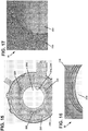
- FIGs 15 and 16 simulated results of mold flow analysis of 3-gate design are shown in which the gates 220 are located more proximate the central aperture 204 than they are to the outer perimeter 202.
- the orientation of the fibers 230 shown in Figures 15 and 16 is in the transverse direction in the area of the seal grooves 214, 216.
- the gating system shown in Figures 14 and 15 is sufficient to form a composite part, this approach can result in fibers oriented in the transverse direction, as shown in Figure 15 and 16 .
- the 100x photograph provided at Figure 17 shows this condition, where it can be seen that the predominant orientation is in the transverse direction (into the page). This condition can reduce the material's fatigue properties by up to 40% over the more preferred, longitudinal direction. This unfavorable stress loading was not sufficient to meet the targeted cycles to failure.
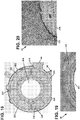
- FIG. 18-20 an optimized gating and molding approach is shown in which seven gates 220 are provided that are located more proximate the outer perimeter 202 than to the central aperture 204.
- This configuration results in a more random configuration at the high stress regions (some combination of aligned and unaligned fiber orientation) as evidenced by the 100x photograph provided at Figure 20 .
- the optimal gate configuration included a three pin gate system arranged around the part outer perimeter 202. This gate design provides a more random orientation along the seal grooves 214, 216 which results in a fatigue life prediction that met the application requirements. Additionally, the negative effects of warpage and flatness due to the gate relocation are considered minimal, compared to the three gate configuration.
- the number of material flow fronts is also increased. Mold flow analysis was again used to evaluate the location and temperature of the knit lines. Knit lines occur when two flow fronts meet; with both flow fronts rapidly cooling there is less intermingling of the resin and fiber. The result is a lower strength area.
- the gates 220 are located such that the location of the knit lines avoids the internal port 212 from the valve 42, a region with minimal wall thickness and such that the knit lines formed are at temperatures that would still allow for some co-mingling of fronts which would minimize strength reduction.
- collapsible cores and removable pins may be utilized to aid in forming the cavity areas.
- collapsible cores can be used to form the seal grooves 214, 216 and/or outlet channel 210.
- the internal ports 208 and 212 can be formed around a pin that is removed after the molding process.
- the resulting opening in the outer perimeter 202 of the body 30 can be sealed by heat staking or by another process, such as the insertion of a plug.
- the disclosed plenum housing body 30 has been shown through modelling and testing to have a fatigue performance sufficient to meet the application performance and life requirements, according to the component durability requirements. Simultaneously, the disclosed plenum body housing 30 yields a 30% weight savings over a standard aluminum component while maintaining the same durability/life as the base aluminum version.
Landscapes
- Engineering & Computer Science (AREA)
- General Engineering & Computer Science (AREA)
- Mechanical Engineering (AREA)
- Manufacturing & Machinery (AREA)
- Physics & Mathematics (AREA)
- Fluid Mechanics (AREA)
- Retarders (AREA)
Description
- The present disclosure relates generally to limited-slip differential assemblies. More particularly, the present disclosure relates to a differential assembly having an improved plenum housing body.
- Limited-slip differentials have been developed that use a hydraulically actuated clutch to limit differential rotation between the output shafts of the differential. Such limited-slip differentials can include a pump in the form of a gerotor incorporated into the differential housing. Solenoid valves have been used to precisely control the actuation pressure provided to the clutch. However, to be operable, such valves require an electronic controller and valve control hardware/software. Example limited-slip differentials are disclosed at
U.S. Pat. Nos. 4,012,968 ;5,310,388 ;6,332,522 ;6,733,411 ;6,789,657 ;7,361,144 ;7,448,482 ; and8,043,184 . - A differential of the type is disclosed also in
WO 2013/155138 . - Furthermore,
US 2006/0076209 A1 discloses a differential assembly comprising a plenum housing body, with all the features of the preamble of claim 1. - A plenum housing is a common metal (e.g. aluminum) component provided on differential assemblies. A plenum housing typically features a low pressure in-feed and a high pressure control. Such plenums generally supply low pressure fluid (under vacuum) to an integrated pump in the differential and feature a high pressure passageway from the pressurized actuator cavity in the differential. The plenum can also retain a valve which regulates the pressure of the differential system.
- Vehicle emissions can be reduced through the development and usage of new materials and processes not traditionally used in the automotive industry besides exclusive applications. Metal replacement with lighter weight components and design optimization can have a doubly rewarding effect; namely, a lighter vehicle system not only requires less road load power for motivation, but also allows for smaller, usually more efficient powertrain options, which tend to be more efficient still. This can be accomplished, in part, by adapting composite materials that have typically been available only to the upper end of the market and specialty racing applications. The specific component detailed in the teachings herein highlight the challenges and rewards for metal replacement with an injection molded, fiber reinforced plastic for usage in mass produced drivetrain systems, namely in an electronic limited slip differential (eLSD).
- In one aspect, the component detailed herein is a differential assembly having a mechanical plenum that serves as a hydraulic supply, a fluid pressure control and a structural body for an eLSD system. Not only does the design approach for the component qualify for weight savings through material comparison, but its processing also allows for sub-component integration, further reducing final assembly complexity and lowering production cost. Material and production tooling costs are also favorable due to the net-shape processing allowed via injection molding.
- The injection molded design replaces a previously permanent molded aluminum with an injection molded, short glass fiber reinforced polymer. This disclosure describes the challenges and advantages of design and processing that have allowed the plenum to be optimized for the lightweighting of the eLSD system. A general design approach encompassing the myriad activities necessary for a transition from metal to plastic is also discussed that highlights the lessons learned during the process of readying the component for the transition from research and development prototype into production acceptance.
- According to the present invention, a differential assembly having a pump and a plenum housing body is disclosed according to claim 1. The plenum housing body includes a low pressure inlet and a high pressure outlet configured to receive a control valve. The plenum housing body also defines a fluid inlet channel in fluid communication with the low pressure inlet via a first internal port and is being configured to be in fluid communication with an inlet side of the pump when the plenum housing body is assembled onto the differential assembly. The plenum housing body also defines a fluid outlet channel in fluid communication with the high pressure outlet via a second internal port and can be configured to be in fluid communication with an outlet side of the pump when the plenum housing body is assembled onto the differential assembly. The plenum housing is being formed as a net-shape fiber reinforced plastic material including chopped fibers, for example, chopped fiberglass fibers, and an epoxy resin.
- According to another aspect of the present invention, a method for making a plenum housing body for a differential assembly having a pump is also disclosed in claim 8. The method includes the steps of providing a mold cavity defining a central aperture of the plenum housing body and an outer perimeter of the plenum housing body and injecting a fiber reinforced plastic material including chopped fibers and an epoxy resin into the mold cavity through a plurality of gates. The method can also include injecting the fiber reinforced plastic material through a plurality of gates that are located closer in proximity to the outer perimeter than to the central aperture. The fiber reinforced plastic material includes chopped fiberglass fibers.
- The plenum's main loading and stress comes from pressurized axle gear oil that is the hydraulic system's working fluid. The plenum has high pressure passageways and a central ID groove that commutes fluid from the differential to the control valve. The ID high pressure groove is opposed by two dynamic, high pressure seals. Other parts of the assembly include a low pressure, dynamic lip seal and filter as well as a bushing. The plenum is a stationary component while being an assembled piece on the rotating differential; therefore, it has integrated anti-rotation features.
- Preferred embodiments are laid down in the dependent claims. A variety of additional aspects will be set forth in the description that follows. These aspects can relate to individual features and to combinations of features, however the subject-matter for which protection is sought is defined by the claims. It is to be understood that both the foregoing general description and the following detailed description are exemplary and explanatory only and are not restrictive of the invention as disclosed by the claims, upon which the examples disclosed herein are based.
-
-
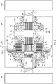
Figure 1 is a perspective view of a differential incorporating a limited-slip driveline apparatus in accordance with the principles of the present disclosure. -
Figure 2 is a cross-sectional view cut longitudinally through the differential ofFigure 2 . -
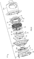
Figure 3 is an exploded, perspective view of the differential ofFigure 1 . -
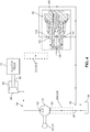
Figure 4 schematically depicts a hydraulic actuation circuit of the limited-slip driveline apparatus incorporated into the differential ofFigure 1 . -
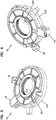
Figure 5 is a top perspective view of a plenum housing body of the differential shown inFigure 1 . -
Figure 6 is a top perspective view of the plenum housing body shown inFigure 5 . -
Figure 7 is a bottom perspective view of the plenum housing body shown inFigure 5 . -
Figure 8 is a bottom perspective view of the plenum housing body shown inFigure 5 . -
Figure 9 is a top view of the plenum housing body shown inFigure 5 . -
Figure 10 is a bottom view of the plenum housing body shown inFigure 5 . -
Figure 11 is a side view of the plenum housing body shown inFigure 5 . -
Figure 12 is a cross-sectional view of the plenum housing body shown inFigure 5 taken along the line 12-12 inFigure 9 . -
Figure 13 is a cross-sectional view of the plenum housing body shown inFigure 5 taken along the line 13-13 inFigure 9 . -
Figure 14 is a cross-sectional view of the plenum housing body shown inFigure 5 taken along the line 14-14 inFigure 9 . -
Figure 15 is a schematic of the plenum housing body shown inFigure 5 showing predicted fiber orientation from a first molding process. -
Figure 16 is an enlarged perspective view of the schematic of the plenum housing body shown inFigure 15 . -
Figure 17 is a photographic view showing actual fiber orientation resulting from the first molding process. -
Figure 18 is a schematic of the plenum housing body shown inFigure 5 showing predicted fiber orientation from a second molding process. -
Figure 19 is an enlarged perspective view of the schematic of the plenum housing body shown inFigure 18 . -
Figure 20 is a photographic view showing actual fiber orientation resulting from the second molding process. - Reference will now be made in detail to exemplary aspects of the present disclosure that are illustrated in the accompanying drawings. Wherever possible, the same reference numbers will be used throughout the drawings to refer to the same or like structures.
- As disclosed herein in
Figures 1-4 , a limited-slip driveline apparatus in accordance with the principles of the present teachings has been incorporated into a differential assembly. It will be appreciated that while the limited-slip driveline apparatus has specifically been shown incorporated into a differential, the various aspects of the present disclosure are applicable to any type of driveline apparatus having a clutch for controlling relative rotation between two driveline components. As used herein, the term "clutch" means any structure that uses friction to control relative rotation between two components. -
Figure 1 illustrates a differential 20 incorporating a limited-slip driveline apparatus in accordance with the principles of the present disclosure. The differential 20 includes adifferential housing 22 that in use is rotated about arotation axis 24.Bearings 26 are provided at opposite ends of thedifferential housing 22. Thebearings 26 are co-axially aligned along therotation axis 24 and are configured for rotatably mounting thedifferential housing 22 within an outer housing 28 (e.g., a differential carrier as shown schematically inFigure 2 ). Theouter housing 28 contains a hydraulic fluid such as oil that can be used for lubricating various components (e.g. gears) within theouter housing 28 and thedifferential housing 22. - A
plenum housing 30, discussed in greater detail in the following section, is mounted at one end of thedifferential housing 22. Thedifferential housing 22 is rotatable relative to theplenum housing 30 about therotation axis 24. Theplenum housing 30 includestabs 31 that engages theouter housing 28 to prevent relative rotation between theplenum housing 30 and theouter housing 28. A hydraulic fluid pump 32 (seeFigs. 2 and3 ) is provided within thedifferential housing 22. Thehydraulic fluid pump 32 is part of ahydraulic actuation circuit 34 that extends through theplenum housing 30 and thedifferential housing 22. The volume of oil within theouter housing 28 forms areservoir 36 of thehydraulic circuit 34. Thehydraulic fluid pump 32 draws oil from thereservoir 36 through aninput port 38 defined by theplenum housing 30 and outputs oil back to thereservoir 36 through anoutput port 40 defined by theplenum housing 30. Aflow regulating valve 42 regulates a hydraulic fluid flow rate through thehydraulic circuit 34. In one embodiment, theflow regulating valve 42 prevents the hydraulic fluid flow rate within thehydraulic actuation circuit 34 from exceeding a set maximum flow rate regardless of a magnitude of the fluid pressure generated by thehydraulic fluid pump 32 within thehydraulic circuit 34. - Referring to
Figures 2 and3 , it can be seen that thedifferential housing 22 includes afirst housing piece 22A and asecond housing piece 22B that meet at aninterface 23. Thehousing pieces differential housing 22 defines aflange 44 adjacent theinterface 23 for mounting aring gear 46. In use of the differential 20, thering gear 46 intermeshes with abevel gear 48 driven by adriveshaft 50. As thebevel gear 48 is rotated by thedriveshaft 50, thebevel gear 48 engages thering gear 46 thereby causing rotation of thedifferential housing 22 about therotation axis 24. Theplenum housing body 30 can be sealed against thefirst housing piece 22A withseal members - Referring still to
Figure 2 , the differential 20 includes atorque transfer arrangement 52 mounted within thesecond housing piece 22B. Thetorque transfer arrangement 52 includes first and second side gears 54, 56 (e.g., sun gears) that respectively defineoutput shaft openings rotation axis 24. Thetorque transfer arrangement 52 also includes a planetary gear set 62 mounted between the first and second side gears 54, 56. The planetary gear set 62 is configured for transferring torque between thedifferential housing 22 and the first and second side gears 54, 56 while concurrently permitting the first and second side gears 54, 56 to rotate relative to one another (e.g., at different rotational speeds) about therotation axis 24. The planetary gear set 62 includes pinion gears 64 rotatably mounted on ashaft 66 fixed relative to thedifferential housing 22. Each of the pinion gears 64 intermeshes with both thefirst side gear 54 and thesecond side gear 56. - The differential 20 also includes a clutch 70 mounted within the
second housing piece 22B. The clutch 70 includes acoupler 72 defining anoutput shaft opening 74 coaxially aligned with therotation axis 24. Thecoupler 72 carries a plurality of afriction plates 76 that project radially outwardly from the main body of thecoupler 72. Thefriction plates 76 are rotationally fixed relative to the main body of thecoupler 72. The clutch 70 also includes a plurality ofeared discs 78 that are carried by thedifferential housing 22. Thediscs 78 are rotationally fixed relative to thedifferential housing 22. Theeared discs 78 are interleaved between thefriction plates 76 to form aclutch pack 77. The clutch 70 is configured to resist relative rotation between thecoupler 72 and thedifferential housing 22 at least when the clutch is actuated. When the clutch 70 is actuated, thefriction plates 76 are preferably compressed against theeared discs 78 so that friction resists relative rotation between thefriction plates 76 and theeared discs 78. The differential 20 further includes an actuation arrangement for actuating the clutch 70 by compressing theclutch pack 77. The actuation arrangement includes apiston 80 mounted within apiston housing 82. Thepiston 80 of the present teachings includes ornamental features beyond the technical and functional features disclosed herein. - A
pressure chamber 84 is defined between thepiston 80 and thepiston housing 82. Thepiston 80 is moveable relative to thepiston housing 82 along therotation axis 24. The actuation arrangement also includes thehydraulic fluid pump 32. When thehydraulic fluid pump 32 pumps hydraulic fluid through thehydraulic actuation circuit 34, thepressure chamber 34 is pressurized thereby causing thepiston 80 to slide along therotation axis 24 toward theclutch pack 77. As thepiston 80 is forced against theclutch pack 77 by hydraulic pressure within thepressure chamber 84, thefriction plates 76 and theeared discs 78 are compressed together such that the clutch 70 is actuated. Meaningful braking/actuation of the clutch 70 does not take place until the hydraulic pressure in thepressure chamber 84 reaches a predetermined level. - The
hydraulic fluid pump 32 of the differential 20 is depicted as a gerotor pump. Thehydraulic fluid pump 32 includes aninner gear 90 having anoutput shaft opening 92 that is coaxially aligned with therotation axis 24. Thehydraulic fluid pump 32 also includes anouter gear 94 positioned outside theinner gear 90. Theouter gear 94 is positioned within aneccentric sleeve 96. Theeccentric sleeve 96 is coupled to thedifferential housing 22 so that theeccentric sleeve 96 is carried by thedifferential housing 22 as thedifferential housing 22 rotates about therotation axis 24. In this way, theeccentric sleeve 96 is configured to rotate in concert with thedifferential housing 22. The inner andouter gears eccentric sleeve 96. As shown atFigure 3 , theinner gear 90 includesouter teeth 98 that engageinner teeth 100 of theouter gear 94. Theinner teeth 100 of theouter gear 94 include one more tooth than theouter teeth 98 of theinner gear 90. When relative rotation is generated between theeccentric sleeve 96 and theinner gear 90, the teeth of the inner andouter gears outer gears - In use of the differential 22, first and
second output shafts 102, 104 (seeFigure 2 ) are preferably coupled to the differential 20. The first andsecond output shafts second wheels second output shaft 104 is rotatably received within anoutput shaft opening 110 defined by thesecond housing piece 22B of thedifferential housing 22. Thesecond output shaft 104 is also rotationally fixed within the output shaft opening 60 of thesecond side gear 56 by means such as splines. Thefirst output shaft 102 is rotatably received within anoutput shaft opening 112 defined by thefirst housing piece 22A. Thefirst output shaft 102 is also rotationally fixed within theoutput shaft opening 92 defined by theinner gear 90 of the gerotor pump, theoutput shaft opening 74 defined by thecoupler 72 of the clutch 70, and theoutput shaft opening 58 defined by thefirst side gear 54. It will be appreciated that splined connections can be used to provide the fixed rotational connection between thefirst output shaft 102 and theinner gear 90, thecoupler 72 and thefirst side gear 54. In this way, thefirst side gear 54, thecoupler 72, and theinner gear 90 all rotate in concert (i.e., unison) with thefirst output shaft 102 as thefirst output shaft 102 is rotated about therotation axis 24. Because of this relationship, when the clutch 70 is actuated, the clutch functions to control the relative rotational speed between the entire assembly (i.e., thefirst output shaft 102, theinner gear 90, thecoupler 72 and the first side gear 54) and thedifferential housing 22. - In view of the above, it will be appreciated the
hydraulic pump 32 is coupled between thedifferential housing 22 and thefirst output shaft 102 so that relative rotation between thefirst output shaft 102 and thedifferential housing 22 causes thepump 32 to pump hydraulic fluid through thehydraulic actuation circuit 34. For example, theeccentric sleeve 96 is non-rotationally coupled to thedifferential housing 22 and theinner gear 90 is non-rotationally coupled to thefirst output shaft 102. Because thehydraulic pump 32 is coupled between thedifferential housing 22 and thefirst output shaft 102, the speed of the hydraulic pump and thus the flow rate generated by the pump is directly dependent on the relative rotational speed between thedifferential housing 22 and thefirst output shaft 102. In one example, the pump displaces a fixed volume of hydraulic fluid at a given relative rotational speed. - It will be appreciated that the limited-slip clutch apparatus is configured to allow a limited amount of relative rotation between the
differential housing 22 and thefirst output shaft 102 while preventing the relative rotation from exceeding a predetermined rate. In one embodiment, the predetermined maximum amount of relative rotation permitted is about 60 rotations per minute. This rate of relative rotation is suitable for allowing thewheels wheels wheels second wheel 108 slips and thefirst wheel 106 stops, theeccentric sleeve 96 coupled to the rotatingdifferential housing 22 will drive theouter gear 94 about theinner gear 90 such that thehydraulic pump 32 pumps fluid through theactuation circuit 34 to actuate the clutch 70. In this situation, actuation of the clutch 70 causes increased torque to be transferred from thedifferential housing 22 to thefirst output shaft 102 thereby causing rotation of thefirst output shaft 102 and thefirst wheel 106. In the case where thefirst wheel 106 slips and thesecond wheel 108 stops, theinner gear 90 coupled to the first output shaft 102 (which is rotating faster than the differential housing 22) will drive theinner gear 90 relative to theouter gear 94 such that thehydraulic pump 32 pumps fluid through theactuation circuit 34 to actuate the clutch 70. In this situation, actuation of the clutch 70 brakes/resists rotation of thefirst output shaft 102 relative to thedifferential housing 22 causing increased torque to be transferred through thedifferential housing 22 and thetorque transfer arrangement 52 to thesecond output shaft 104 thereby causing rotation of thesecond output shaft 104 and thefirst wheel 106. - Referring to
Figure 4 , when theflow regulating valve 42 is mounted within the valve mounting opening 41 of theplenum housing 30, theinlet port 138 is placed in fluid communication with thepressure chamber 84 and the variablesize outlet orifice 141 is placed in fluid communication with theoutlet port 40. Thehydraulic actuation circuit 34 of the actuator arrangement extends from thereservoir 36 through theinput port 38 of theplenum housing 30 to aninlet 150 of thehydraulic fluid pump 32. Thehydraulic circuit 34 then passes through thehydraulic fluid pump 32 to anoutlet 152 of thehydraulic fluid pump 32. From theoutlet 152 of thehydraulic fluid pump 32, thehydraulic circuit 34 extends to thepressure chamber 84. From thepressure chamber 84, thehydraulic circuit 34 extends back through thedifferential housing 22 and theplenum housing 30 to the inlet opening 138 of theflow regulating valve 42. From the inlet opening 138 thehydraulic circuit 34 extends through thevalve 42 to theoutlet orifice 141. Thehydraulic circuit 134 then extends from theoutlet orifice 141 to theoutput port 40 back to thereservoir 36. - When the first and
second output shafts rotation axis 24, relative rotation is generated between thefirst output shaft 102 and thedifferential housing 22. This relative rotation generates relative rotation between thesleeve 96 and theinner gear 90 of thehydraulic fluid pump 32 thereby causing thehydraulic fluid pump 32 to draw hydraulic fluid from thereservoir 36 through theinput port 38 and into theinlet 150 of thehydraulic fluid pump 32. The hydraulic fluid then flows through thehydraulic fluid pump 32 and is discharged from theoutlet 152 of thehydraulic fluid pump 32 toward thepressure chamber 84. The fluid flow within thehydraulic circuit 34 flow then proceeds from thepressure chamber 84 to theflow regulating valve 42. The flow enters theflow regulating valve 42 through theinlet port 38 and exits through theoutlet orifice 141. As long as the flow rate is below the set maximum flow rate of theflow regulating valve 42, thespring 146 retains theflow regulating valve 42 in the full open position and flow proceeds unregulated through theoutlet orifice 141 and back to thereservoir 36 through theoutlet port 40. In this situation, the hydraulic pressure upstream of the flow regulating valve 42 (i.e., the hydraulic pressure provided at the pressure chamber 84) is sufficiently low that no meaningful actuation of the clutch 70 occurs. - It will be appreciated that the flow rate generated by the
hydraulic fluid pump 32 is directly related (e.g., directly proportional) to the relative rotational speed between thefirst output shaft 102 and thedifferential housing 22. Thus, as the relative rotational speed between thefirst output shaft 102 and thedifferential housing 22 increases, the flow rate generated by thehydraulic fluid pump 32 increases accordingly until the flow rate reaches the set maximum flow rate of thevalve 42. When the flow rate generated by thehydraulic fluid pump 32 reaches the set maximum flow rate of theflow regulating valve 42, theflow regulating valve 42 begins to regulate flow by varying the size of theorifice 141 so that the flow passing through theflow regulating valve 42 does not exceed the set maximum flow rate regardless of the pressure within thecircuit 34. - When the
flow regulating valve 42 regulates flow by restricting theoutlet orifice 141, the hydraulic pressure within thehydraulic actuating circuit 34 upstream of thevalve 42 increases thereby increasing the force supplied by thepiston 90 to theclutch pack 77 to a level where meaningful actuation/braking occurs. In this way, the increased hydraulic pressure provides an increased breaking action that prevents the relative rotational speed between thefirst output shaft 102 and thedifferential housing 22 from exceeding a predetermined value corresponding to the set maximum flow rate of theflow regulating valve 42. In one example embodiment, the set maximum flow rate passing through theflow regulating valve 42 equals .25 gallons per minute and the maximum relative rotational speed between thefirst output shaft 102 and thedifferential housing 22 is 60 rotations per minute. - Referring to
Figures 5-14 , theplenum housing body 30 is shown in greater detail. Theplenum 30 of the present teachings includes ornamental features beyond the technical and functional features disclosed herein. As discussed previously, theplenum housing body 30 has alow pressure inlet 38 and ahigh pressure outlet 40, wherein the high pressure outlet is configured to receive the regulatingvalve 42. Theplenum housing body 30 defines anouter perimeter 202 at which theinlet 38 andoutlet 40 are located and further defines acentral aperture 204. - In one aspect, the
plenum housing body 30 defines afluid inlet channel 206 that is in fluid communication with thelow pressure inlet 38 via a firstinternal port 208. Once theplenum housing body 30 is assembled onto the differential, thefluid inlet channel 206 is in fluid communication withlow pressure inlet 150 of thepump 32 such that fluid from thereservoir 36 can be drawn into thepump 32 through theport 208 andchannel 206. - In one aspect, the
plenum housing body 30 defines afluid outlet channel 210 that is in fluid communication with thehigh pressure outlet 40 via a secondinternal port 212. Once theplenum housing body 30 is assembled onto the differential, thefluid outlet channel 210 is in fluid communication with theoutlet 152 of thepump 32 such that fluid from thepump 32 can be delivered to thevalve 42 through theport 212 andchannel 210. - In one aspect, the
fluid outlet channel 210 is formed between afirst seal groove 214 and asecond seal groove 216, wherein thefirst seal groove 214 is defined between a first wall 214a and asecond wall 214b and thesecond seal groove 216 is defined between athird wall 216a and afourth wall 216b. Theseal grooves seals fluid outlet channel 210 to be sealed against a surface of the rotatingfirst housing piece 22A. As shown, thefluid outlet channel 210 is defined between the second andthird walls wall 218. - The
root portion 218 is provided with a radius or curved shape such to reduce stress at this area of theplenum housing body 30. An analysis conducted by the inventors showed that the predicted failure mode for a composite plenum housing would be fatigue cracking at the root of the inner andouter seal grooves 214, 216 -a result of the cantilevering effect of the deflected seal groove. The analysis showed that the maximum stress could be decreased by half and deflection reduced by more than 60% by reducing the depth of the seal grooves by 50 percent (over a standard aluminum housing seal groove depth) and increasing the radius of theroot portion 218 from 0.4 millimeters to 0.8 millimeters. Adding wall thickness at the area of theroot portion 218 has also been shown to reduce stress in this area (e.g. increase wall thickness by 0.5 mm over that found in a corresponding aluminum plenum housing). The combination of these combined design features has been shown to increase the estimated fatigue cycles (at 140°C) by a factor of about 8 over a non-optimized composite plenum housing. - The second
internal port 212 is provided with an ovular or racetrack shaped cross-section to further reduce stress by eliminating sharp corners in the design. As shown, the secondinternal port 212 extends into the second andthird walls channel 210 and theoutlet 40. This design enables enough flow such that only a singleinternal port 212 is necessary. However, additional internal ports may be provided, if desired. - In one aspect, the
plenum housing body 30 can be produced as a net-shape fiber reinforced plastic material including chopped fibers and an epoxy resin. By use of the term "net-shape" it is meant that the part is essentially finished coming out of the mold and does not require significant machining or other processing after the molding process is complete. In one aspect, the disclosed design of theplenum housing body 30 is optimized for injection molding to have the same performance as a typical aluminum version. Material selection was based on stresses identified in an original aluminum finite element analysis and by using material specifications at 150°C (423.15 K) (application temperature). As a result of the analysis, it was determined that a material composition with sufficient strength and tensile modulus at 150°C (423.15 K) was a composition including 60 percent by weight chopped high temperature nylon glass fibers and 40% epoxy resin. In addition to meeting application requirement for strength and stiffness, this percentage of fibers also contributes to a reduction in overall part shrinkage and warpage. - Orientation of the fibers within the
plenum housing body 30 can also have a major influence on the overall strength and fatigue resistance of the component. There are several approaches that can be taken to account for fiber orientation, for example, finite element and mold analysis can be run using material properties given in the data sheet for 100% alignment (longitudinal) and run using 30% of the given material properties. This 30% "knock-down" in properties was selected to represent the non-aligned state or transverse orientation in which the matrix (e.g. epoxy) is loaded instead of the fibers. Based on mold flow outputs, fiber orientation in a specific area can be predicted and properties can be assigned (either longitudinal, transverse or the mean of the two to represent random orientation). - One goal of the design is to maximize the loading of the fibers (strength phase) at high stress areas which can be done by matching FEA results of high stress areas with fibers aligned longitudinally to the stresses. Referring to
Figures 15 and 16 , simulated results of mold flow analysis of 3-gate design are shown in which thegates 220 are located more proximate thecentral aperture 204 than they are to theouter perimeter 202. The orientation of thefibers 230 shown inFigures 15 and 16 is in the transverse direction in the area of theseal grooves Figures 14 and15 is sufficient to form a composite part, this approach can result in fibers oriented in the transverse direction, as shown inFigure 15 and 16 . The 100x photograph provided atFigure 17 shows this condition, where it can be seen that the predominant orientation is in the transverse direction (into the page). This condition can reduce the material's fatigue properties by up to 40% over the more preferred, longitudinal direction. This unfavorable stress loading was not sufficient to meet the targeted cycles to failure. - Referring to
Figures 18-20 , an optimized gating and molding approach is shown in which sevengates 220 are provided that are located more proximate theouter perimeter 202 than to thecentral aperture 204. This configuration results in a more random configuration at the high stress regions (some combination of aligned and unaligned fiber orientation) as evidenced by the 100x photograph provided atFigure 20 . Through analysis, it was determined that the optimal gate configuration included a three pin gate system arranged around the partouter perimeter 202. This gate design provides a more random orientation along theseal grooves - By increasing the number of pin gates the number of material flow fronts is also increased. Mold flow analysis was again used to evaluate the location and temperature of the knit lines. Knit lines occur when two flow fronts meet; with both flow fronts rapidly cooling there is less intermingling of the resin and fiber. The result is a lower strength area. In the disclosed design, the
gates 220 are located such that the location of the knit lines avoids theinternal port 212 from thevalve 42, a region with minimal wall thickness and such that the knit lines formed are at temperatures that would still allow for some co-mingling of fronts which would minimize strength reduction. - As the disclosed
plenum housing body 30 requires extended exposure to synthetic gear oil at elevated temperature, a material evaluation was undertaken on a coupon level. The chemical resistance testing was performed at elevated temperatures (exceeding the application temperatures as a method to accelerate testing) for 500 hours to verify dimensional stability and resistance to absorption of environmental and working fluids. Tensile coupons of the material were used for this testing. Fluids tested were typical synthetic gear oils that would be used in the eLSD application. Tensile testing was done on tensile samples untested as a baseline. Each coupon was measured before and after soak to evaluate dimensional stability. Coupons were soaked at 100°C (373.15 K) and 120°C (393.15 K) for 100 hours and 500 hours. Dimensional change at maximum conditions (120°C/500 hours) was negligible. Material strength was 98% retained after maximum testing conditions. The conclusion of the chemical resistance testing was that the selected materials was resistant to the relevant fluids and exhibited little to negligible change after ageing. - When forming the disclosed
plenum housing body 30, collapsible cores and removable pins may be utilized to aid in forming the cavity areas. For example, collapsible cores can be used to form theseal grooves outlet channel 210. Theinternal ports outer perimeter 202 of thebody 30 can be sealed by heat staking or by another process, such as the insertion of a plug. - The disclosed
plenum housing body 30 has been shown through modelling and testing to have a fatigue performance sufficient to meet the application performance and life requirements, according to the component durability requirements. Simultaneously, the disclosedplenum body housing 30 yields a 30% weight savings over a standard aluminum component while maintaining the same durability/life as the base aluminum version. - The above specification provides examples of how certain inventive aspects may be put into practice.
Claims (15)
- A differential assembly (22) having a pump (32) and a plenum housing body (30), the plenum housing body (30) comprising:a. a low pressure inlet (38);b. a high pressure outlet (40) configured to receive a control valve (42);c. a fluid inlet channel (206) in fluid communication with the low pressure inlet (38) via a first internal port (208) and being configured to be in fluid communication with an inlet (150) side of the pump (32) when the plenum housing body (30) is assembled onto the differential assembly (22); andd. a fluid outlet channel (210) in fluid communication with the high pressure outlet (40) via a second internal port (212) and being configured to be in fluid communication with an outlet (152) side of the pump (32) when the plenum housing body (30) is assembled onto the differential assembly (22);
characterized in that:
the plenum housing body (30) is formed as a net-shape fiber reinforced plastic material including chopped fibers (230) and an epoxy resin. - The differential assembly of claim 1, wherein the plenum housing body (30) defines a central aperture (204) having inwardly facing radial first and second seal grooves (214, 216) for receiving seal members (33 a, 33b), the first seal groove (214) being defined between a first wall (214a) and a second wall (214b) and the second seal groove (216) being defined between a third wall (216a) and a fourth wall (216b), wherein the fluid outlet channel (210) is disposed between the first and second seal grooves (214, 216) and is defined between the second and third walls (214b, 216a) joined by a fifth wall (218) having a first radius.
- The differential assembly (22) of claim 1, wherein the second internal port (212) has an oval shaped cross-section.
- The differential assembly (22) of claim 2, wherein the chopped fibers (230) proximate the first and second seal grooves (214, 216) and the fluid outlet channel (210) are aligned generally parallel to the first through fourth walls (214a, 214b, 216a, 216b) to a greater degree than the chopped fibers aligned generally orthogonal to the first through fourth walls.
- The differential assembly (22) of claim 2, wherein the plenum housing body (30) defines an outer perimeter (202) and wherein the plenum housing body (30) includes mold gate vestiges that are closer in proximity to the outer perimeter (202) than to the central aperture (204).
- The differential assembly (22) of claim 2, wherein the plenum housing body (30) includes molded knit lines that are non-intersecting with the first and second internal ports (208, 212).
- The differential assembly (22) of claim 1, wherein the fiber reinforced plastic material includes about 60 percent by weight chopped fiberglass fibers and about 40 percent by weight epoxy resin.
- A method for making a plenum housing body (30) for a differential assembly (22) according to claim 1, the method comprising:a. providing a mold cavity defining a central aperture (204) of the plenum housing body (30) and an outer perimeter (202) of the plenum housing body (30); andb. injecting a fiber reinforced plastic material including chopped fibers (230) and an epoxy resin into the mold cavity through a plurality of gates.
- The method for making the plenum housing body (30) of claim 8, wherein the step of injecting includes injecting the fiber reinforced plastic material through a plurality of gates that are located closer in proximity (202) to the outer perimeter than to the central aperture (204).
- The method for making the plenum housing body (30) of claim 9, wherein the step of injecting includes injecting the fiber reinforced plastic material through the gates such that knit lines formed between the gates are non-intersecting with first and second internal ports (208, 212) defined in the plenum housing body (30).
- The method for making the plenum housing body (30) of claim 8, wherein the step of injecting a fiber reinforced plastic material includes injecting a material that is about 60 percent by weight chopped fiberglass fibers (230) and about 40 percent by weight epoxy resin.
- The method for making the plenum housing body (30) of claim 8, further including the step of providing one or more collapsible cores to define seal grooves (214, 216) at the central aperture (204).
- The method for making the plenum housing body (30) of claim 12, further including the step of providing one or more removable pins to define internal ports (208, 212) within the plenum housing body (30).
- The method for making the plenum housing body (30) of claim 13, further including the step of removing the one or more removable pins after the plastic material has cured.
- The method for making the plenum housing body (30) of claim 14, further including the step of sealing one or more openings created by removing the one or more removable pins by heat-staking the one or more openings.
Applications Claiming Priority (4)
| Application Number | Priority Date | Filing Date | Title |
|---|---|---|---|
| US201462063367P | 2014-10-13 | 2014-10-13 | |
| US201562140559P | 2015-03-31 | 2015-03-31 | |
| US201562153136P | 2015-04-27 | 2015-04-27 | |
| PCT/US2015/055365 WO2016061124A1 (en) | 2014-10-13 | 2015-10-13 | Fiber reinforced plenum for limited-slip differential |
Publications (3)
| Publication Number | Publication Date |
|---|---|
| EP3207287A1 EP3207287A1 (en) | 2017-08-23 |
| EP3207287A4 EP3207287A4 (en) | 2018-05-23 |
| EP3207287B1 true EP3207287B1 (en) | 2019-09-25 |
Family
ID=55747227
Family Applications (1)
| Application Number | Title | Priority Date | Filing Date |
|---|---|---|---|
| EP15851381.2A Active EP3207287B1 (en) | 2014-10-13 | 2015-10-13 | Fiber reinforced plenum for limited-slip differential |
Country Status (4)
| Country | Link |
|---|---|
| US (3) | USD735758S1 (en) |
| EP (1) | EP3207287B1 (en) |
| CN (1) | CN107110327B (en) |
| WO (1) | WO2016061124A1 (en) |
Families Citing this family (4)
| Publication number | Priority date | Publication date | Assignee | Title |
|---|---|---|---|---|
| USD735758S1 (en) | 2014-10-13 | 2015-08-04 | Eaton Corporation | Composite differential plenum |
| USD835165S1 (en) * | 2016-10-21 | 2018-12-04 | Torq-Masters Industries, Inc. | Automatic locking differential |
| US10436307B2 (en) * | 2017-02-27 | 2019-10-08 | GM Global Technology Operations LLC | Composite axle housing and methods of manufacturing thereof |
| WO2021180368A1 (en) * | 2020-03-10 | 2021-09-16 | Eaton Intelligent Power Limited | Threaded connection to carrier for hydraulic connection to a case with an externally mounted plenum tube |
Family Cites Families (54)
| Publication number | Priority date | Publication date | Assignee | Title |
|---|---|---|---|---|
| US2714314A (en) | 1951-05-15 | 1955-08-02 | Howden James & Co Ltd | Rotors for rotary gas compressors and motors |
| US3490312A (en) * | 1968-05-31 | 1970-01-20 | Gen Motors Corp | Expansible chamber device with hydrodynamic bearing pump and limited slip differential employing same |
| US4012968A (en) | 1974-12-23 | 1977-03-22 | Borg-Warner Corporation | Speed-sensitive differential mechanism |
| US4214507A (en) | 1977-08-24 | 1980-07-29 | Vries Donald S Jr De | One-piece plastic piston |
| DE8129402U1 (en) | 1981-10-08 | 1983-08-11 | Fritz Himmermann GmbH & Co KG, 5374 Hellenthal | RING PISTON FOR MULTI-DISC CLUTCH |
| SE468122B (en) | 1990-04-27 | 1992-11-09 | Svenska Rotor Maskiner Ab | ROTOR OPERATES A SCREW ROTOR, A SCREW ROTOR, AND A PROCEDURE FOR MANUFACTURING A ROTOR |
| JPH05256364A (en) | 1992-03-12 | 1993-10-05 | Aisin Seiki Co Ltd | Hydraulic piston made of resin |
| US5310388A (en) | 1993-02-10 | 1994-05-10 | Asha Corporation | Vehicle drivetrain hydraulic coupling |
| JPH05272639A (en) | 1992-03-30 | 1993-10-19 | Nissan Motor Co Ltd | Fiber-reinforced plastic made piston |
| US5526797A (en) | 1994-01-07 | 1996-06-18 | Stokes; Richard A. | Methods and apparatus for vaporizing and utilizing fuels of various octane ratings |
| US6109615A (en) * | 1998-06-05 | 2000-08-29 | Skf Usa Inc. | Plenum oil seal |
| US6059680A (en) | 1999-04-23 | 2000-05-09 | Dana Corporation | Speed sensitive on-demand torque coupling differential |
| US6238315B1 (en) * | 1999-12-16 | 2001-05-29 | David Marshall Morse | Hydraulic coupling for vehicle drivetrain |
| US6332522B1 (en) * | 2000-05-26 | 2001-12-25 | Dana Corporation | Hydraulic coupling for vehicle drivetrain |
| US6733411B1 (en) * | 2002-01-31 | 2004-05-11 | Dana Corporation | Electronically controlled hydraulic actuator for limited slip differential assembly |
| FR2839157A1 (en) | 2002-04-30 | 2003-10-31 | Koninkl Philips Electronics Nv | ULTRASONIC IMAGING SYSTEM WITH HIGH SIDE RESOLUTION |
| US6719362B1 (en) | 2002-10-31 | 2004-04-13 | Valeo Electrical Systems, Inc. | Integrated lower cowl/plenum and wiper drive module |
| US6814399B2 (en) | 2002-10-31 | 2004-11-09 | Valeo Electrical Systems, Inc. | Plastic molded product for aligning and supporting a rotatable shaft and process for making same |
| US6918851B2 (en) | 2002-11-06 | 2005-07-19 | Dana Corporation | Concentric shift system for engaging an interaxle differential lock |
| US6789657B2 (en) | 2002-12-04 | 2004-09-14 | Daimlerchrysler Corporation | Pressure regulation of speed sensing electronic limited slip differential for axles |
| PL1604135T3 (en) | 2003-03-20 | 2010-02-26 | Bosch Rexroth Ag | Non-return valve |
| US8327738B2 (en) * | 2003-11-07 | 2012-12-11 | Sikorsky Aircraft Corporation | Composite transmission housing with discontinuous fiber preforms |
| US7318509B2 (en) | 2004-05-05 | 2008-01-15 | Gkn Driveline North America, Inc. | Temperature compensating hydraulic shear pump |
| US7131201B2 (en) * | 2004-05-14 | 2006-11-07 | Eaton Corporation | Coupling device and improved method of assembly thereof |
| US20050261101A1 (en) | 2004-05-24 | 2005-11-24 | Jun Yoshioka | Torque coupling differential assembly with torque disconnect |
| US7063198B2 (en) * | 2004-10-13 | 2006-06-20 | Eaton Corporation | Coupling device and improved fluid pressure system therefor |
| US7341136B2 (en) * | 2005-08-25 | 2008-03-11 | Torque-Traction Technologies, Llc. | Hydraulic fluid plenum plate assembly |
| US7549941B2 (en) | 2005-09-09 | 2009-06-23 | Eaton Corporation | Vehicle differential including pump with variable-engagement clutch |
| US20070077379A1 (en) | 2005-09-30 | 2007-04-05 | Magna International Inc. | Water-assist injection molded structural members |
| US7448482B2 (en) | 2005-10-07 | 2008-11-11 | Dana Automotive Systems Group, Llc | Electro-magnetic actuator for torque coupling with variable pressure-relief valve |
| US7341536B2 (en) | 2005-10-20 | 2008-03-11 | Dana Corporation | Light weight differential case half |
| JP4706431B2 (en) | 2005-10-21 | 2011-06-22 | 株式会社ジェイテクト | Vehicle differential, vehicle hybrid differential, and vehicle differential case |
| CA2976893C (en) | 2005-12-09 | 2019-03-12 | Fallbrook Intellectual Property Company Llc | Continuously variable transmission |
| US8011289B2 (en) | 2006-01-13 | 2011-09-06 | Bwi Company Limited S.A. | Half-sleeved and sleeveless plastic piston pumps |
| JP2007239972A (en) | 2006-03-13 | 2007-09-20 | Aisin Chem Co Ltd | Ring shaped piston |
| CN102278200B (en) | 2006-06-26 | 2014-05-14 | 福博科知识产权有限责任公司 | Continuously variable transmission |
| US20080023918A1 (en) | 2006-07-28 | 2008-01-31 | Dynetek Industries Ltd. | Leak-by sealing system for a shuttle piston |
| EP2059382A4 (en) | 2006-08-29 | 2009-09-02 | Magna Int Inc | STRUCTURAL ELEMENTS MOLDED BY INJECTION USING WATER |
| EP2094988A4 (en) * | 2006-12-19 | 2016-03-09 | Magna Powertrain Usa Inc | HYDRAULIC COUPLER |
| US20090193966A1 (en) | 2008-02-06 | 2009-08-06 | Gm Global Technology Operations, Inc. | Compressor Piston |
| US7980983B2 (en) * | 2008-02-25 | 2011-07-19 | Chrysler Group Llc | Hydraulically locking limited slip differential |
| US9080622B2 (en) * | 2009-04-03 | 2015-07-14 | Eaton Corporation | Hydraulic coupling having self-adjusting anti-rotation hydraulic fluid path |
| EP2470796B1 (en) | 2009-08-26 | 2017-03-22 | Parker Hannifin Manufacturing France - Etablissement de Colombes | Composite piston accumulator |
| US8459137B1 (en) | 2010-04-07 | 2013-06-11 | Hydro-Gear Limited Partnership | Control assembly for drive system |
| AU2012224318B2 (en) * | 2011-02-28 | 2015-12-03 | Toray Industries, Inc. | Thermoplastic resin composition and molded product thereof |
| WO2012167248A2 (en) | 2011-06-02 | 2012-12-06 | Eaton Corporation | Simplified roots-type blower |
| DE102011112584B4 (en) | 2011-09-08 | 2015-12-31 | Mann + Hummel Gmbh | Crankcase breather |
| US9964195B2 (en) * | 2012-04-13 | 2018-05-08 | Eaton Intelligent Power Limited | Limited-slip driveline apparatus |
| USD736260S1 (en) | 2012-07-03 | 2015-08-11 | Eaton Corporation | Composite differential piston |
| USD735758S1 (en) | 2014-10-13 | 2015-08-04 | Eaton Corporation | Composite differential plenum |
| US8951155B2 (en) | 2012-10-10 | 2015-02-10 | Eaton Corporation | Differential having externally mounted plenum |
| CN202883932U (en) * | 2012-11-13 | 2013-04-17 | 象山申达轿车配件厂 | Differential housing |
| WO2014175972A2 (en) * | 2013-03-15 | 2014-10-30 | Eaton Corporation | Improved constructions for load-bearing structures; advantageous metal-plastic composite constructions; methods of preparation and assembly; systems and methods |
| DE102013225065B4 (en) * | 2013-12-06 | 2016-04-14 | Ksb Aktiengesellschaft | Pump housing in plastic construction |
-
2012
- 2012-07-03 US US29/426,304 patent/USD735758S1/en active Active
-
2015
- 2015-06-18 US US29/530,633 patent/USD749136S1/en active Active
- 2015-10-13 WO PCT/US2015/055365 patent/WO2016061124A1/en not_active Ceased
- 2015-10-13 US US15/518,881 patent/US10591039B2/en active Active
- 2015-10-13 EP EP15851381.2A patent/EP3207287B1/en active Active
- 2015-10-13 CN CN201580063491.7A patent/CN107110327B/en active Active
Non-Patent Citations (1)
| Title |
|---|
| None * |
Also Published As
| Publication number | Publication date |
|---|---|
| WO2016061124A1 (en) | 2016-04-21 |
| US20170241534A1 (en) | 2017-08-24 |
| USD749136S1 (en) | 2016-02-09 |
| CN107110327B (en) | 2020-06-02 |
| US10591039B2 (en) | 2020-03-17 |
| CN107110327A (en) | 2017-08-29 |
| EP3207287A1 (en) | 2017-08-23 |
| USD735758S1 (en) | 2015-08-04 |
| EP3207287A4 (en) | 2018-05-23 |
Similar Documents
| Publication | Publication Date | Title |
|---|---|---|
| US10591039B2 (en) | Fiber reinforced plenum for limited-slip differential | |
| EP2836741B1 (en) | Limited-slip driveline apparatus | |
| DE102009002481A1 (en) | Hydrodynamic coupling arrangement, in particular torque converter | |
| US9982673B2 (en) | Supercharger having integrated clutch and torsional damper | |
| WO2008074289A1 (en) | Multifunctional torque converter with clutches arranged axially in series, and method for controlling the hydraulic pressure and the liquid flow | |
| WO2010113018A1 (en) | Hydraulic coupling having improved hydraulic porting path design | |
| DE112009005373T5 (en) | Fluid transfer device | |
| CN101688569A (en) | Dual clutch with cooling distribution reservoir chambers | |
| US9416827B1 (en) | Clutch assembly with dual actuation piston | |
| EP2550467B1 (en) | Hydraulic coupling having improved hydraulic porting path design | |
| DE102007017430B4 (en) | Outer plate with drive tongue for bow springs for a damper of a torque converter | |
| DE112012000335T5 (en) | Hydraulic control device | |
| US9284993B1 (en) | Clutch assembly with dual actuation piston | |
| EP1574737A1 (en) | Coupling device and improved method of controlling torque transmission | |
| DE102019134484B4 (en) | TORQUE CONVERTER ASSEMBLY | |
| DE102017100403A1 (en) | BRIDGE COUPLING FOR A TORQUE TRANSFORMER | |
| EP2559878A1 (en) | Cooling system, in particular for a motor vehicle | |
| US7241247B1 (en) | Torque coupling with control valve | |
| CN1763394A (en) | Coupling device and clutch lubrication arrangement improved therefor | |
| DE102016115564B4 (en) | DOUBLE PUMP SYSTEM OF A TRANSMISSION | |
| CN105569759B (en) | Hydraulic valve and camshaft phase adjuster | |
| DE102012219361A1 (en) | Fluid system i.e. hydraulic oil system, for powertrain of motor car, has fluid displacement unit representing transmission element in powertrain and comprising controller for to- and/fro flowing volumetric stream | |
| DE102015217582B4 (en) | Hydraulic actuator for actuating a friction clutch | |
| DE102009042826B4 (en) | Wet clutch with torsional vibration damper | |
| CN109154374B (en) | Torque converter one-way flow device and method for implementing lock-up clutch application |
Legal Events
| Date | Code | Title | Description |
|---|---|---|---|
| STAA | Information on the status of an ep patent application or granted ep patent |
Free format text: STATUS: THE INTERNATIONAL PUBLICATION HAS BEEN MADE |
|
| PUAI | Public reference made under article 153(3) epc to a published international application that has entered the european phase |
Free format text: ORIGINAL CODE: 0009012 |
|
| STAA | Information on the status of an ep patent application or granted ep patent |
Free format text: STATUS: REQUEST FOR EXAMINATION WAS MADE |
|
| 17P | Request for examination filed |
Effective date: 20170502 |
|
| AK | Designated contracting states |
Kind code of ref document: A1 Designated state(s): AL AT BE BG CH CY CZ DE DK EE ES FI FR GB GR HR HU IE IS IT LI LT LU LV MC MK MT NL NO PL PT RO RS SE SI SK SM TR |
|
| AX | Request for extension of the european patent |
Extension state: BA ME |
|
| DAV | Request for validation of the european patent (deleted) | ||
| DAX | Request for extension of the european patent (deleted) | ||
| A4 | Supplementary search report drawn up and despatched |
Effective date: 20180420 |
|
| RIC1 | Information provided on ipc code assigned before grant |
Ipc: B29K 105/12 20060101ALN20180417BHEP Ipc: F16H 48/18 20060101AFI20180417BHEP Ipc: B29K 309/08 20060101ALN20180417BHEP Ipc: B29L 31/00 20060101ALN20180417BHEP Ipc: F16H 48/27 20120101ALI20180417BHEP Ipc: F16H 48/38 20120101ALI20180417BHEP Ipc: B29K 63/00 20060101ALN20180417BHEP Ipc: F16H 48/08 20060101ALN20180417BHEP Ipc: B29C 45/00 20060101ALI20180417BHEP Ipc: F16H 48/32 20120101ALN20180417BHEP |
|
| GRAP | Despatch of communication of intention to grant a patent |
Free format text: ORIGINAL CODE: EPIDOSNIGR1 |
|
| STAA | Information on the status of an ep patent application or granted ep patent |
Free format text: STATUS: GRANT OF PATENT IS INTENDED |
|
| RIC1 | Information provided on ipc code assigned before grant |
Ipc: B29K 63/00 20060101ALN20190327BHEP Ipc: F16H 48/27 20120101ALI20190327BHEP Ipc: B29K 105/12 20060101ALN20190327BHEP Ipc: F16H 48/18 20060101AFI20190327BHEP Ipc: B29L 31/00 20060101ALN20190327BHEP Ipc: F16H 48/38 20120101ALI20190327BHEP Ipc: F16H 48/08 20060101ALN20190327BHEP Ipc: B29K 309/08 20060101ALN20190327BHEP Ipc: B29C 45/00 20060101ALI20190327BHEP Ipc: F16H 48/32 20120101ALN20190327BHEP |
|
| INTG | Intention to grant announced |
Effective date: 20190416 |
|
| RIN1 | Information on inventor provided before grant (corrected) |
Inventor name: FRAZIER, DANIEL STANLEY Inventor name: WILLIAMS, KELLY ANN Inventor name: MAPKAR, JAVED ABDURRAZZAQ |
|
| GRAS | Grant fee paid |
Free format text: ORIGINAL CODE: EPIDOSNIGR3 |
|
| GRAA | (expected) grant |
Free format text: ORIGINAL CODE: 0009210 |
|
| STAA | Information on the status of an ep patent application or granted ep patent |
Free format text: STATUS: THE PATENT HAS BEEN GRANTED |
|
| AK | Designated contracting states |
Kind code of ref document: B1 Designated state(s): AL AT BE BG CH CY CZ DE DK EE ES FI FR GB GR HR HU IE IS IT LI LT LU LV MC MK MT NL NO PL PT RO RS SE SI SK SM TR |
|
| REG | Reference to a national code |
Ref country code: GB Ref legal event code: FG4D |
|
| REG | Reference to a national code |
Ref country code: CH Ref legal event code: EP |
|
| REG | Reference to a national code |
Ref country code: AT Ref legal event code: REF Ref document number: 1184123 Country of ref document: AT Kind code of ref document: T Effective date: 20191015 |
|
| REG | Reference to a national code |
Ref country code: IE Ref legal event code: FG4D |
|
| REG | Reference to a national code |
Ref country code: DE Ref legal event code: R096 Ref document number: 602015038814 Country of ref document: DE |
|
| REG | Reference to a national code |
Ref country code: NL Ref legal event code: MP Effective date: 20190925 |
|
| PG25 | Lapsed in a contracting state [announced via postgrant information from national office to epo] |
Ref country code: LT Free format text: LAPSE BECAUSE OF FAILURE TO SUBMIT A TRANSLATION OF THE DESCRIPTION OR TO PAY THE FEE WITHIN THE PRESCRIBED TIME-LIMIT Effective date: 20190925 Ref country code: FI Free format text: LAPSE BECAUSE OF FAILURE TO SUBMIT A TRANSLATION OF THE DESCRIPTION OR TO PAY THE FEE WITHIN THE PRESCRIBED TIME-LIMIT Effective date: 20190925 Ref country code: NO Free format text: LAPSE BECAUSE OF FAILURE TO SUBMIT A TRANSLATION OF THE DESCRIPTION OR TO PAY THE FEE WITHIN THE PRESCRIBED TIME-LIMIT Effective date: 20191225 Ref country code: BG Free format text: LAPSE BECAUSE OF FAILURE TO SUBMIT A TRANSLATION OF THE DESCRIPTION OR TO PAY THE FEE WITHIN THE PRESCRIBED TIME-LIMIT Effective date: 20191225 Ref country code: SE Free format text: LAPSE BECAUSE OF FAILURE TO SUBMIT A TRANSLATION OF THE DESCRIPTION OR TO PAY THE FEE WITHIN THE PRESCRIBED TIME-LIMIT Effective date: 20190925 Ref country code: HR Free format text: LAPSE BECAUSE OF FAILURE TO SUBMIT A TRANSLATION OF THE DESCRIPTION OR TO PAY THE FEE WITHIN THE PRESCRIBED TIME-LIMIT Effective date: 20190925 |
|
| REG | Reference to a national code |
Ref country code: LT Ref legal event code: MG4D |
|
| PG25 | Lapsed in a contracting state [announced via postgrant information from national office to epo] |
Ref country code: LV Free format text: LAPSE BECAUSE OF FAILURE TO SUBMIT A TRANSLATION OF THE DESCRIPTION OR TO PAY THE FEE WITHIN THE PRESCRIBED TIME-LIMIT Effective date: 20190925 Ref country code: GR Free format text: LAPSE BECAUSE OF FAILURE TO SUBMIT A TRANSLATION OF THE DESCRIPTION OR TO PAY THE FEE WITHIN THE PRESCRIBED TIME-LIMIT Effective date: 20191226 Ref country code: RS Free format text: LAPSE BECAUSE OF FAILURE TO SUBMIT A TRANSLATION OF THE DESCRIPTION OR TO PAY THE FEE WITHIN THE PRESCRIBED TIME-LIMIT Effective date: 20190925 |
|
| REG | Reference to a national code |
Ref country code: AT Ref legal event code: MK05 Ref document number: 1184123 Country of ref document: AT Kind code of ref document: T Effective date: 20190925 |
|
| PG25 | Lapsed in a contracting state [announced via postgrant information from national office to epo] |
Ref country code: AT Free format text: LAPSE BECAUSE OF FAILURE TO SUBMIT A TRANSLATION OF THE DESCRIPTION OR TO PAY THE FEE WITHIN THE PRESCRIBED TIME-LIMIT Effective date: 20190925 Ref country code: NL Free format text: LAPSE BECAUSE OF FAILURE TO SUBMIT A TRANSLATION OF THE DESCRIPTION OR TO PAY THE FEE WITHIN THE PRESCRIBED TIME-LIMIT Effective date: 20190925 Ref country code: EE Free format text: LAPSE BECAUSE OF FAILURE TO SUBMIT A TRANSLATION OF THE DESCRIPTION OR TO PAY THE FEE WITHIN THE PRESCRIBED TIME-LIMIT Effective date: 20190925 Ref country code: PL Free format text: LAPSE BECAUSE OF FAILURE TO SUBMIT A TRANSLATION OF THE DESCRIPTION OR TO PAY THE FEE WITHIN THE PRESCRIBED TIME-LIMIT Effective date: 20190925 Ref country code: AL Free format text: LAPSE BECAUSE OF FAILURE TO SUBMIT A TRANSLATION OF THE DESCRIPTION OR TO PAY THE FEE WITHIN THE PRESCRIBED TIME-LIMIT Effective date: 20190925 Ref country code: PT Free format text: LAPSE BECAUSE OF FAILURE TO SUBMIT A TRANSLATION OF THE DESCRIPTION OR TO PAY THE FEE WITHIN THE PRESCRIBED TIME-LIMIT Effective date: 20200127 Ref country code: IT Free format text: LAPSE BECAUSE OF FAILURE TO SUBMIT A TRANSLATION OF THE DESCRIPTION OR TO PAY THE FEE WITHIN THE PRESCRIBED TIME-LIMIT Effective date: 20190925 Ref country code: RO Free format text: LAPSE BECAUSE OF FAILURE TO SUBMIT A TRANSLATION OF THE DESCRIPTION OR TO PAY THE FEE WITHIN THE PRESCRIBED TIME-LIMIT Effective date: 20190925 |
|
| PG25 | Lapsed in a contracting state [announced via postgrant information from national office to epo] |
Ref country code: SM Free format text: LAPSE BECAUSE OF FAILURE TO SUBMIT A TRANSLATION OF THE DESCRIPTION OR TO PAY THE FEE WITHIN THE PRESCRIBED TIME-LIMIT Effective date: 20190925 Ref country code: CZ Free format text: LAPSE BECAUSE OF FAILURE TO SUBMIT A TRANSLATION OF THE DESCRIPTION OR TO PAY THE FEE WITHIN THE PRESCRIBED TIME-LIMIT Effective date: 20190925 Ref country code: IS Free format text: LAPSE BECAUSE OF FAILURE TO SUBMIT A TRANSLATION OF THE DESCRIPTION OR TO PAY THE FEE WITHIN THE PRESCRIBED TIME-LIMIT Effective date: 20200224 Ref country code: SK Free format text: LAPSE BECAUSE OF FAILURE TO SUBMIT A TRANSLATION OF THE DESCRIPTION OR TO PAY THE FEE WITHIN THE PRESCRIBED TIME-LIMIT Effective date: 20190925 |
|
| REG | Reference to a national code |
Ref country code: CH Ref legal event code: PL |
|
| REG | Reference to a national code |
Ref country code: DE Ref legal event code: R097 Ref document number: 602015038814 Country of ref document: DE |
|
| PG2D | Information on lapse in contracting state deleted |
Ref country code: IS |
|
| PG25 | Lapsed in a contracting state [announced via postgrant information from national office to epo] |
Ref country code: LI Free format text: LAPSE BECAUSE OF NON-PAYMENT OF DUE FEES Effective date: 20191031 Ref country code: CH Free format text: LAPSE BECAUSE OF NON-PAYMENT OF DUE FEES Effective date: 20191031 Ref country code: DK Free format text: LAPSE BECAUSE OF FAILURE TO SUBMIT A TRANSLATION OF THE DESCRIPTION OR TO PAY THE FEE WITHIN THE PRESCRIBED TIME-LIMIT Effective date: 20190925 Ref country code: LU Free format text: LAPSE BECAUSE OF NON-PAYMENT OF DUE FEES Effective date: 20191013 Ref country code: IS Free format text: LAPSE BECAUSE OF FAILURE TO SUBMIT A TRANSLATION OF THE DESCRIPTION OR TO PAY THE FEE WITHIN THE PRESCRIBED TIME-LIMIT Effective date: 20200126 |
|
| PLBE | No opposition filed within time limit |
Free format text: ORIGINAL CODE: 0009261 |
|
| STAA | Information on the status of an ep patent application or granted ep patent |
Free format text: STATUS: NO OPPOSITION FILED WITHIN TIME LIMIT |
|
| REG | Reference to a national code |
Ref country code: BE Ref legal event code: MM Effective date: 20191031 |
|
| PG25 | Lapsed in a contracting state [announced via postgrant information from national office to epo] |
Ref country code: BE Free format text: LAPSE BECAUSE OF NON-PAYMENT OF DUE FEES Effective date: 20191031 Ref country code: MC Free format text: LAPSE BECAUSE OF FAILURE TO SUBMIT A TRANSLATION OF THE DESCRIPTION OR TO PAY THE FEE WITHIN THE PRESCRIBED TIME-LIMIT Effective date: 20190925 |
|
| 26N | No opposition filed |
Effective date: 20200626 |
|
| GBPC | Gb: european patent ceased through non-payment of renewal fee |
Effective date: 20191225 |
|
| PG25 | Lapsed in a contracting state [announced via postgrant information from national office to epo] |
Ref country code: GB Free format text: LAPSE BECAUSE OF NON-PAYMENT OF DUE FEES Effective date: 20191225 Ref country code: IE Free format text: LAPSE BECAUSE OF NON-PAYMENT OF DUE FEES Effective date: 20191013 Ref country code: FR Free format text: LAPSE BECAUSE OF NON-PAYMENT OF DUE FEES Effective date: 20191125 Ref country code: ES Free format text: LAPSE BECAUSE OF FAILURE TO SUBMIT A TRANSLATION OF THE DESCRIPTION OR TO PAY THE FEE WITHIN THE PRESCRIBED TIME-LIMIT Effective date: 20190925 |
|
| PG25 | Lapsed in a contracting state [announced via postgrant information from national office to epo] |
Ref country code: SI Free format text: LAPSE BECAUSE OF FAILURE TO SUBMIT A TRANSLATION OF THE DESCRIPTION OR TO PAY THE FEE WITHIN THE PRESCRIBED TIME-LIMIT Effective date: 20190925 |
|
| PG25 | Lapsed in a contracting state [announced via postgrant information from national office to epo] |
Ref country code: CY Free format text: LAPSE BECAUSE OF FAILURE TO SUBMIT A TRANSLATION OF THE DESCRIPTION OR TO PAY THE FEE WITHIN THE PRESCRIBED TIME-LIMIT Effective date: 20190925 |
|
| PG25 | Lapsed in a contracting state [announced via postgrant information from national office to epo] |
Ref country code: HU Free format text: LAPSE BECAUSE OF FAILURE TO SUBMIT A TRANSLATION OF THE DESCRIPTION OR TO PAY THE FEE WITHIN THE PRESCRIBED TIME-LIMIT; INVALID AB INITIO Effective date: 20151013 Ref country code: MT Free format text: LAPSE BECAUSE OF FAILURE TO SUBMIT A TRANSLATION OF THE DESCRIPTION OR TO PAY THE FEE WITHIN THE PRESCRIBED TIME-LIMIT Effective date: 20190925 |
|
| PG25 | Lapsed in a contracting state [announced via postgrant information from national office to epo] |
Ref country code: TR Free format text: LAPSE BECAUSE OF FAILURE TO SUBMIT A TRANSLATION OF THE DESCRIPTION OR TO PAY THE FEE WITHIN THE PRESCRIBED TIME-LIMIT Effective date: 20190925 |
|
| PG25 | Lapsed in a contracting state [announced via postgrant information from national office to epo] |
Ref country code: MK Free format text: LAPSE BECAUSE OF FAILURE TO SUBMIT A TRANSLATION OF THE DESCRIPTION OR TO PAY THE FEE WITHIN THE PRESCRIBED TIME-LIMIT Effective date: 20190925 |
|
| P01 | Opt-out of the competence of the unified patent court (upc) registered |
Effective date: 20230521 |
|
| PGFP | Annual fee paid to national office [announced via postgrant information from national office to epo] |
Ref country code: DE Payment date: 20250923 Year of fee payment: 11 |