EP3206483B1 - Automatic ball launcher - Google Patents
Automatic ball launcher Download PDFInfo
- Publication number
- EP3206483B1 EP3206483B1 EP15866103.3A EP15866103A EP3206483B1 EP 3206483 B1 EP3206483 B1 EP 3206483B1 EP 15866103 A EP15866103 A EP 15866103A EP 3206483 B1 EP3206483 B1 EP 3206483B1
- Authority
- EP
- European Patent Office
- Prior art keywords
- ball
- adjustment knob
- platform
- hammer
- tension
- Prior art date
- Legal status (The legal status is an assumption and is not a legal conclusion. Google has not performed a legal analysis and makes no representation as to the accuracy of the status listed.)
- Active
Links
- 238000000034 method Methods 0.000 claims description 28
- 230000006835 compression Effects 0.000 claims description 9
- 238000007906 compression Methods 0.000 claims description 9
- 230000013011 mating Effects 0.000 claims 2
- 241000282472 Canis lupus familiaris Species 0.000 description 25
- 230000000694 effects Effects 0.000 description 5
- 241000282465 Canis Species 0.000 description 4
- 230000008901 benefit Effects 0.000 description 3
- 230000008859 change Effects 0.000 description 3
- 238000013461 design Methods 0.000 description 3
- 230000007246 mechanism Effects 0.000 description 3
- 241001465754 Metazoa Species 0.000 description 2
- 238000010304 firing Methods 0.000 description 2
- 230000005484 gravity Effects 0.000 description 2
- 238000012549 training Methods 0.000 description 2
- 210000004128 D cell Anatomy 0.000 description 1
- HBBGRARXTFLTSG-UHFFFAOYSA-N Lithium ion Chemical compound [Li+] HBBGRARXTFLTSG-UHFFFAOYSA-N 0.000 description 1
- 238000013459 approach Methods 0.000 description 1
- 210000000988 bone and bone Anatomy 0.000 description 1
- 230000001419 dependent effect Effects 0.000 description 1
- 230000009977 dual effect Effects 0.000 description 1
- 238000009429 electrical wiring Methods 0.000 description 1
- 238000005516 engineering process Methods 0.000 description 1
- 230000002452 interceptive effect Effects 0.000 description 1
- 229910001416 lithium ion Inorganic materials 0.000 description 1
- 230000004048 modification Effects 0.000 description 1
- 238000012986 modification Methods 0.000 description 1
- 230000007935 neutral effect Effects 0.000 description 1
- 230000008569 process Effects 0.000 description 1
- 230000004044 response Effects 0.000 description 1
Images


Classifications
-
- F—MECHANICAL ENGINEERING; LIGHTING; HEATING; WEAPONS; BLASTING
- F41—WEAPONS
- F41B—WEAPONS FOR PROJECTING MISSILES WITHOUT USE OF EXPLOSIVE OR COMBUSTIBLE PROPELLANT CHARGE; WEAPONS NOT OTHERWISE PROVIDED FOR
- F41B7/00—Spring guns
-
- A—HUMAN NECESSITIES
- A01—AGRICULTURE; FORESTRY; ANIMAL HUSBANDRY; HUNTING; TRAPPING; FISHING
- A01K—ANIMAL HUSBANDRY; CARE OF BIRDS, FISHES, INSECTS; FISHING; REARING OR BREEDING ANIMALS, NOT OTHERWISE PROVIDED FOR; NEW BREEDS OF ANIMALS
- A01K15/00—Devices for taming animals, e.g. nose-rings or hobbles; Devices for overturning animals in general; Training or exercising equipment; Covering boxes
- A01K15/02—Training or exercising equipment, e.g. mazes or labyrinths for animals ; Electric shock devices ; Toys specially adapted for animals
-
- A—HUMAN NECESSITIES
- A63—SPORTS; GAMES; AMUSEMENTS
- A63B—APPARATUS FOR PHYSICAL TRAINING, GYMNASTICS, SWIMMING, CLIMBING, OR FENCING; BALL GAMES; TRAINING EQUIPMENT
- A63B65/00—Implements for throwing ; Mechanical projectors, e.g. using spring force
- A63B65/12—Ball-throwing apparatus with or without catchers ; Mechanical projectors, e.g. using spring force
-
- A—HUMAN NECESSITIES
- A63—SPORTS; GAMES; AMUSEMENTS
- A63B—APPARATUS FOR PHYSICAL TRAINING, GYMNASTICS, SWIMMING, CLIMBING, OR FENCING; BALL GAMES; TRAINING EQUIPMENT
- A63B69/00—Training appliances or apparatus for special sports
- A63B69/40—Stationarily-arranged devices for projecting balls or other bodies
- A63B69/407—Stationarily-arranged devices for projecting balls or other bodies with spring-loaded propelling means
- A63B69/408—Stationarily-arranged devices for projecting balls or other bodies with spring-loaded propelling means with rotating propelling arm
-
- A—HUMAN NECESSITIES
- A63—SPORTS; GAMES; AMUSEMENTS
- A63B—APPARATUS FOR PHYSICAL TRAINING, GYMNASTICS, SWIMMING, CLIMBING, OR FENCING; BALL GAMES; TRAINING EQUIPMENT
- A63B2208/00—Characteristics or parameters related to the user or player
- A63B2208/14—Characteristics or parameters related to the user or player specially adapted for animals
Definitions
- the present inventive concept relates to the field of animal exercising devices. More particularly, the invention relates to a device that launches a ball (such as a tennis ball), and that has an open top which allows the dog to return the ball and re-load it into the ball launching device, whereupon the ball is re-launched automatically.
- a ball such as a tennis ball
- Another category of ball launching devices is the solenoid, or "firing ram” launcher.
- U.S. Patent No. 6,571,743 entitled “Remote Control Ball Ejector” provides an example of such a launcher. This launcher is electrically powered and remotely controlled to actuate linear movement of a striking arm, thereby causing the ejection of a ball from a housing.
- U.S. Patent No. 6,176,230 uses another striking technology for launching a ball in the form of a so-called hammer.
- the '230 patent is entitled "Portable Projectile Launcher for Pet Amusement.”
- the hammer relies upon rotational movement of a striking arm rather than the linear motion used by a firing arm.
- the hammer of the '230 patent is marketed under the name GoDogGo® Fetching Machine.
- the GoDogGo® pet product is promoted as an automatic ball thrower that is designed specifically for dogs "to allow for independent fetch or owner-controlled play [using a] remote control.
- GoDogGo interactive ball toy is designed with an Automatic Sensor & Safety Switch with Auto Stop Feature so GoDogGo [sic] will NOT run, rotate or launch unless a ball is in the ready position.” See http://www.godoggoinc.com/ .
- the safety switch of the GoDogGo® product is a gravity switch that is activated when a ball rolls into position; it is not a safety switch for animals or people in the path of the launched ball.
- fly wheel device employs a pair of adjacent rotating wheels to hurl an object. Fly wheel launchers are commonly used to throw baseballs and footballs for team or player practice. Recently, fly wheel launchers have been adapted for use in launching tennis balls for dogs.
- U.S. Patent Nos. 7,691,012 and 8,287,404 entitled “Programmable Ball Throwing Apparatus” present examples of fly wheel ball throwing devices.
- U.S. Patent Publ. No. 2013/0228138 entitled "Pet Exercise and Entertainment Device” offers another ball launching device that uses fly wheels. This device is marketed by Hamill Partners, LLC of Austin, Texas as the iFtech®. The iFetch® pet product is promoted at http://goifetch.com. The iFetch® product requires motors to drive separate wheels (described in the application as wheels 226) at high speed, and increased drive power to support the dual motors. Additionally, to keep costs down, the iFetch® pet products are somewhat miniaturized and require specially-purchased miniature tennis balls.
- US4,168,695A discloses a portable ball throwing machine employing a battery-operated motor for projecting tennis balls for practice purposes. The balls are fed from a bin by means of a ball fence and agitator to a tube which conveys the ball to a ball track.
- a spring biased arm is cocked by the motor and released at the correct point in the cycle by operation of a cam gear and pawl. The arm then strikes the ball projecting it from the machine.
- Included in the device is an arrangement for oscillating the device from side to side to vary the pattern of balls projected from the machine and a gate mechanism to index balls onto the ball track.
- US4,409,953A discloses a toy baseball pitching machine that is particularly adapted to be used by children.
- the machine has a ball pitching arm that oscillates rather than rotates and is capable of pitching a plastic ball to a batter using an "underhand" method of pitching.
- the ball pitching arm is fixed to an oscillatable eccentric arm.
- the eccentric arm is connected to one end of an extension spring, and the arm carries a pivoted pawl.
- the pawl is engaged by a toothed rotating drive wheel to rotate the pitching arm in one direction toward a cocked position with the spring extended. Further rotation of the drive wheel brings the pawl into contact with a stop to pivot the pawl out of engagement with the drive wheel.
- the extended spring then acts on the eccentric arm and pitching arm to rotate the pitching arm in the opposite direction to engage and pitch a ball.
- the drive wheel, pawl, eccentric arm, stop and extension spring are all mounted within a housing; and the pitching arm is outside the housing.
- the machine has a ball storage rack so it is capable of pitching a plurality of balls and is battery powered and includes an automatic shut-off switch, which shuts the pitching machine off when all balls are pitched.
- the invention relates to a ball launching apparatus in accordance with claim 1.
- the invention in a second aspect relates to a method of exercising a dog in accordance with claim 11, wherein such ball launching apparatus is used.
- the ball launching apparatus first comprises a housing.
- the housing serves to contain and at least partially conceal certain mechanized components of the system, including an electrical drive motor.
- the housing has a supporting base and an interior compartment.
- the ball launching apparatus also includes a funnel.
- the funnel resides at an upper end of the housing.
- the funnel includes a channel for gravitationally directing a ball into a launch point within the interior compartment.
- a cup is provided below the funnel to secure the received ball at the launch point.
- the ball launching apparatus next includes a chute.
- the chute resides adjacent the launch point.
- the chute defines a through-opening along the housing through which a ball is launched from the launch point.
- the ball launching apparatus further includes a platform.
- the platform resides within the compartment.
- Pivot connection points are provided on opposing perimeter sides of the platform to enable the platform to pivot.
- an angle of the platform relative to the base is adjustable between 20° and 45°. Pivoting the platform adjusts the angle at which the ball is launched through the chute.
- the ball launching apparatus additionally comprises a drive motor.
- the motor is configured to rotate a shaft within the compartment.
- the shaft in turn, rotates a ratchet head having teeth.
- the ball launching apparatus also has an elongated hammer.
- the hammer resides along the platform and has a proximal end, a distal end, and a through-opening for freely (substantially non-frictionally) receiving the shaft.
- the through-opening is at the proximal end of the hammer.
- the hammer is configured such that rotation of the drive shaft operatively causes the distal end of the hammer to be rotated away from the launch point.
- the hammer is biased to rotate a striking surface along the distal end of the hammer back towards the launch point.
- the biasing force is in a clockwise direction.
- the biasing force is generated by a spring.
- the spring resides along the platform and is maintained in tension to provide the biasing force.
- the spring has a first end that is secured to the platform, and a second end that is operatively connected to a proximal end of the hammer through a pin. Rotation of the shaft applies increased tension to the spring to create the biasing force.
- the ball launching apparatus next includes a switch.
- the switch is configured to sense the presence of a ball in the launching point, and then send a signal to initiate rotation of the shaft.
- the switch initiates operation of the drive motor for a cycle of between 5 and 10 seconds.
- the ball launching apparatus also comprises a trigger release arm.
- the trigger release arm has a proximal end and a distal end.
- the trigger release arm is pivotally secured to the platform, while the distal end includes a hook or pawl that is configured to engage a tooth of the ratchet head.
- a tooth of the ratchet head temporarily engages a pawl at the distal end of the trigger release arm. This serves to increase tension held in the spring, thereby loading the biasing force at the proximal end of the hammer.
- a separate tooth in the ratchet head also engages the hammer proximate the shaft, causing rotation of the hammer.
- a flange extending from the proximal end of the hammer is connected to the distal end of the trigger release arm, such as through a pin.
- the housing of the ball launching apparatus comprises a raised portion. This raised portion resides along an upper end of the housing, and is positioned on a side of the housing where the chute is.
- the housing may further include a handle residing along the raised portion.
- a method of exercising a dog is also provided herein.
- the method first includes providing a ball launching apparatus.
- the ball launching apparatus is configured in accordance with the apparatus described above in its various embodiments.
- the method also includes providing a ball to a dog.
- the ball is a standard tennis ball having an outer diameter of between about 2.5 and 2.7 inches.
- the method then comprises training the dog to place the ball into the funnel.
- the switch will sense the presence of the ball once it falls into the launch point.
- the motor is actuated and the hammer strikes the ball, sending it through the chute.
- the dog may then chase (or "fetch") the ball, and return it to the funnel once again. In this way, the dog is self-entertained and exercised.
- the method includes adjusting a tension in the spring, thereby ultimately adjusting the distance in which the ball travels when struck.
- the method may also optionally include adjusting an angle of the platform relative to the base. This has the effect of changing the angle at which the ball is released from the chute. Preferably, making these adjustments is done by turning or, optionally, sliding adjustment knobs residing external to the housing.
- spatially relative terms such as “up,” “down,” “right,” “left,” “beneath,” “below,” “lower,” “above,” “upper” and the like, may be used herein for ease of description to describe one element or feature's relationship to another element(s) or feature(s) as illustrated in the figures. It will be understood that the spatially relative terms are intended to encompass different orientations of the device in use or operation in addition to the orientation depicted in the figures. For example, if the device in the figures is turned over or rotated, elements described as “below” or “beneath” other elements or features would then be oriented “above” the other elements or features. Thus, the exemplary term “below” can encompass both an orientation of above and below. The device may be otherwise oriented (rotated 90 degrees or at other orientations) and the spatially relative descriptors used herein interpreted accordingly.
- ball means a spherical object of any size, so long as the outer diameter is suitable for being received and carried in the mouth of a canine pet.
- pawl means any hook or portion that extends from an arm to engage a tooth.
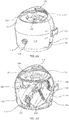
- FIG. 1A is a perspective view of an automatic ball launcher 100 of the present invention, in one embodiment.
- the ball launcher 100 defines a housing 110 having an upper end 112 and a lower end 114.
- the upper end 112 supports a handle 116 that is machined into or otherwise attached to an extended upper portion 118 of the housing 110.
- the handle 116 facilitates lifting and moving of the ball launcher 100.
- the lower end 114 provides a base for supporting the housing 110 and mechanical components once the ball launcher 100 is desirably located.
- the automatic ball launcher 100 is designed to serve as an exercising toy for a canine.
- the launcher 100 allows the canine to retrieve a ball, place the ball into a funnel 120 residing in the upper end 112 of the housing 110, and then wait for a ball 150 to be launched from the housing 110, whereupon the ball 150 may once again be retrieved.
- the ball launcher 100 is configured to launch the ball 150 from a chute 115.
- Figure 1B presents a front elevation view of the ball launcher 100. A ball 150 is partially seen, ready to be launched through the chute 115. In addition, the handle 116 is more clearly seen.
- the handle 116 and the upper extended portion 118 of the housing 110 reside at the front of the ball launcher 100. The reason is that the owner wants the dog to retrieve the ball 150 and place it in the funnel 120 from a back side of the housing 110. This prevents the dog (not shown) from being struck by a next ball 150 that is being launched through the chute 115.
- FIG 2A presents another perspective view of the ball launcher 100 of Figure 1A .
- the view is taken from a rear of the housing 110.
- An optional channel 122 is now visible, formed in the funnel 120.
- the channel 122 directs a ball 150 to a launch point 250 within the housing 110 as the ball 150 gravitationally falls along the funnel 120.
- the funnel 120 is preferably dimensioned to hold several balls in series.
- Figure 2A also shows two features that are related to providing power to the ball launcher 100.
- the first feature is a power switch 125.
- the power switch 125 is preferably a rocker switch designed to provide two basic settings -- on and off.
- the second feature is a female power plug jack 127.
- the jack 127 serves as a receptacle or AC adapter for receiving the tip of a power cord.
- FIG. 2A presents a pair of knobs 130, 140.
- Each knob 130, 140 resides external to the housing 110 and is configured to be rotated to adjust a setting of the ball launcher 100.
- the first knob 130 is a tension adjustment knob.
- the tension adjustment knob 130 allows the pet owner (or toy operator) to adjust the tension of a spring (shown at 420 in the Figure 4 series of drawings) within the housing 110. This, in turn, allows the pet owner to adjust the distance at which the ball 150 is launched from the toy 100.
- the second knob is an angle adjustment knob 140.
- the angle adjustment knob 140 allows the pet owner (or toy operator) to adjust the angle of orientation of a platform (shown at 410 in the Figure 4 series of drawings) within the housing 110. This, in turn, allows the pet owner to adjust the angle at which the ball 150 is launched through the chute 115.
- FIG 2B is another perspective view of the automatic ball launcher 100. This shows the same view as in Figure 2A .
- the housing 110 is cut away, exposing certain components of the automatic ball launcher 100 residing inside of an interior of the housing 110.
- the components include the platform 410, the spring 420 and a cup 450 for holding the ball 150 at a launch point 250.
- Figure 3A is a left side elevation view of the ball launcher of Figure 1A .
- Figure 3B is a right side elevation view of the ball launcher of Figure 1A .
- Each of these views presents the housing 110 and the handle 116.
- Each view also shows the angle adjustment knob 140.
- Figure 3A shows the chute 115, which defines a through-opening through the housing 110.
- Figure 3B shows the tension adjustment knob 130.
- the illustrative tension adjustment knob 130 is in the somewhat cartoonish but aesthetically pleasing form of a dog bone.
- Figure 3B provides a better view of the power switch 115 and the power receptacle 127.
- the ball launcher 100 may also be powered through one or more batteries, or a battery pack (not shown).
- the batteries may be, for example, charged through solar energy. In one aspect, six D-cell batteries are used. Alternatively, a small lithium ion battery may be used.
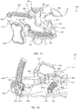
- Figures 4A through 4D present various perspective views of internal components of the automatic ball launcher 100, in a selected embodiment.
- Figure 4A is a front perspective view of the platform 410 of the ball launcher 100
- Figure 4B is a rear view of the platform 410.
- the platform 410 is used to support internal components.
- the platform 410 is designed to pivot along a pair of aligned pivot connection points 432, 433.
- the pivot connection points 432, 433 represent small cylinders that are supported above the platform 410.
- the cylinders 432, 433 are supported on the inside face of the housing 110, forming an axis of rotation.
- pivot connection points 432, 433 may have other arrangements.
- the pivot connection points could define pins that extend outward from the perimeter of the platform 410, and that extend through small through-openings in the housing 110.
- the pivot connection points could define short cylinders that extend outward from the perimeter of the platform 410, and that receive short pins (not shown) that extend inwardly from the housing 110.
- a ball 150 is shown along a launch point 250 on the platform 410.
- the ball 150 is in position to be struck by the elongated hammer 460.
- the cup 450 has a through-opening 455.
- the through-opening 455 accommodates a striking surface 463 of the hammer 460 as it approaches the ball 150.
- the striking surface 463 may optionally have raised patterns, or may have an angled hitting face to impart loft to a struck ball 150.
- the striking surface 463 of the hammer 460 may have removable edges fabricated from different materials that create different launching characteristics of the ball 150 during striking. For example, some interchangeable surfaces 463 may be softer and some may be harder.
- a biasing force is applied to the hammer 460 in order to cause the hammer 460 to move towards the ball 150 .
- the biasing force is applied by a spring 420 that is held in tension.
- the spring 420 has a proximal end that is secured to the platform 410 at a connection pin 422.
- the spring 420 has a distal end 424 that is operatively secured to a proximal end 464 of the hammer 460. More specifically, the distal end 424 of the spring 420 is connected to a flange 468 of the hammer 460.
- Rotation of the proximal end 464 of the hammer 460 away from the connection point 422 of the spring 420 adds tension to the spring 420. A release of that tension causes the striking surface 463 to rapidly rotate towards the ball 150.
- the automatic ball launcher 100 first includes a drive motor 415.
- the drive motor 415 preferably resides on an under-surface 412 of the platform 410.
- the drive motor 415 has a shaft (not visible) that extends up through the platform 410 and connects to a ratchet driver 465.
- the shaft extends up through an opening in the proximal end 464 of the hammer 460 , while the ratchet driver 465 resides over the proximal end 464 of the hammer 460.
- the shaft drives the ratchet driver 465 in a counter-clockwise direction.
- the hammer 460 is free to rotate about the shaft in either direction, not being mechanically coupled to the shaft itself.
- the drive motor 415 will include a gear box that houses the shaft and appropriate electrical wiring.
- the gear box is affixed to the underside of the platform 410 .
- the gear box may also house a micro-processor or circuitry having firmware.
- the micro-processor or circuitry is arranged to communicate with a sensor (not shown) that senses the presence of a ball 150 at the launch point 250. When the sensor senses a ball 150 , a switch sends a signal to initiate rotation of the shaft for a pre-designated period of time, such as 5 to 10 seconds.
- the ratchet driver 465 includes a plurality of teeth 467. In the arrangement of Figures 4A and 4B, the ratchet driver 465 has four teeth 467 equi-radially spaced around the ratchet driver 465.
- the automatic ball launcher 100 also includes a spring adjustment arm 470 .
- the spring adjustment arm 470 is pivotally connected to the platform 410 through a pin 477.
- the spring adjustment arm 470 has a proximal end 472 that resides along the platform 410.
- the proximal end 472 includes a "striking" post 436 , which serves as a rotational stop member of trigger release arm 474 in one direction.
- the proximal end 472 abuts a post 475 , which serves as a rotational stop member of a tensioning gear track 435 in one direction.
- the automatic ball launcher 100 further includes the trigger release arm 474 .
- a distal end of the trigger release arm 474 includes a pair of pawls 471 , 473.
- a first pawl 471 is configured to catch a ratchet tooth 467 as the ratchet driver 465 is rotated.
- a second pawl 473 is pivotally connected to the flange 468 at the proximal end 464 of the hammer 460 by means of pin 461 . In this way, the trigger release arm 474 moves with the proximal end 464 of the hammer 460 .
- the shaft of the drive motor 415 , the hammer 460 , the ratchet driver 465 , and the trigger release arm 474 essentially rotate together to place tension on the spring 420.
- the pawl 471 is held into contact with the ratchet tooth 467' where the spring 420 is mounted between the proximal end 464 of the hammer 460 and the trigger release arm 474.
- the spring adjustment arm 470 includes a strike post 436 .
- the location of the post 436 along the platform is adjusted by using the tension adjustment knob 130 , described more fully below. Rotation of the tension adjustment knob 130 moves the location of the post 436 of the spring adjustment arm 470 , giving input to the trigger release arm 474 at the point where the pawl 471 is to release the ratchet tooth 467'.
- the distal end of the trigger release arm 474 is carried with it. This adds tension to the spring 420.
- the proximal and of the trigger release arm 474 will eventually engage the strike post 436. This, in turn, will cause the trigger release arm 474 to pivot about pin 477, causing the pawl 471 to release the ratchet tooth 467'.
- the hitting arm 460 rapidly rotates the other direction (clockwise) to hit the ball 150, causing the ball 150 to quickly travel (or be launched) through the chute 115.
- the ratchet driver 465 preferably has four teeth 467.
- the multi-tooth arrangement gives the launcher 100 a quicker tension time versus an alternate design, as the spring 420 can be given tension in a smaller angle, that is, on the order of 90° rather than a full 360°.
- the adjustable release location of the trigger release arm 470 allows for varying spring tension releases, which will vary the force in which the ball 150 is hit.
- a first tooth 467' on the ratchet driver 465 engages the first pawl 471 of the trigger release arm 474.
- the second pawl 473 which is operatively connected to the distal end 424 of the spring 420 through pin 461 , moves with the first pawl 471 , loading the spring 420 in the process.
- the second pawl 473 is pivotally connected to the flange 468 at the proximal end 464 of the hammer 460, also by means of the pin 461.
- a second opposing tooth 467" will engage a hook (not shown) along the hammer 460 to cause the flange 466 at the proximal end 464 of the hammer 460 to move with the rotating ratchet driver 465. In either instance, the distal end 462 of the hammer 460 moves away from the ball 150.
- the counter-clockwise rotation of the shaft indirectly turns the hammer 460 counter-clockwise while the ratchet tooth 467' is engaged on the first pawl 471 of the trigger release arm 474.
- Rotation of the shaft adds tension to the spring 420, which in turn is attached to the hammer 460.
- the first tooth 467' will eventually pull away from the first pawl 471, induced by a proximal end of the trigger release arm 474 contacting the post 436.
- the distal end 462 of the hammer 460 will be released from the tooth 467' and will rapidly rotate back towards the ball 150 under the force of the recoiling spring 420.
- the driver motor 415 may immediately stop, or may continue to rotate the shaft for a designated period of time until a next ratchet tooth 467" or 467'" engages the pawl 471.
- the drive shaft will then stop rotating the ratchet driver 465 until a new ball is sensed by the switch at the launch point 250.
- the ratchet teeth 467 on the ratchet driver 465 could vary in number from one to more than one, until the number was so great it would become unfeasible. Less teeth makes the reload time longer because the shaft must turn far enough to pull tension on the spring. If only one tooth is on the ratchet wheel, the shaft must turn 360° to reload the max tension on the spring 420. Where the ratchet driver 465 has four teeth 467, it need only turn 90° to reload the max tension on the spring 420.
- a motion sensor is positioned along a front side of the housing 110. If the motion sensor senses the presence of a person or dog near the chute 115, the drive motor 415 is immediately cut off. This prevents the hammer 420 from striking a ball 150.
- the ball launcher 100 of the present invention allows the operator to indirectly adjust the spring 420 tension. This, in turn, allows the operator to modify the distance at which the ball 150 is launched from the chute 115.
- the ball launcher 100 includes a tension adjustment knob 130.
- the tension adjustment knob 130 is used to turn a tensioning gear 438.
- FIG 4C is an enlarged perspective view of the platform of Figure 4A .
- the tension adjustment knob 130 and the connected tensioning gear 438 are more clearly seen.
- the tensioning gear 438 is connected to the tensioning knob 130 by means of a shaft 432. Rotation of the knob 130 causes the shaft 432 and connected tensioning gear 438 to move a horizontally oriented tensioning gear track 435. This, in turn, moves the spring adjustment arm 470, which adjusts the location of the strike post 436, which ultimately moves the point at which the first tooth 467' of the ratchet driver 465 releases the first pawl 471.
- the effect is to change the amount of tension applied to the spring 420 before the hammer 460 is released to strike a ball 150.
- an optional locking mechanism may be provided.
- pins 137 are placed under the knob 130.
- the pins 137 mate with saw teeth 117 in the housing 110.
- the mated pins 137 and saw teeth 117 hold the knob 130 and operatively connected tensioning gear 438 in place, preventing rotation. This, in turn, prevents movement of the tensioning gear track 435.
- a post 475 is provided along the platform 410.
- the post 475 is a fixed object that prevents movement of the tensioning gear track 435 into the chute 115, where it might interfere with launching of a ball 150. This also acts as a maximum spring tension stop.
- the knob 130 is further secured relative to the housing 110 by means of a compression spring 439.
- the compression spring 439 resides along and is connected to the shaft 132.
- the compression spring 439 biases the knob 130 into the housing 110 so that the pins 137 stayed locked into the saw teeth 117.
- the operator pulls on the knob 130, overcoming the inward biasing force of the spring 439 and releasing the pins 137 from the saw teeth 117.
- the ball launcher 100 of the present invention allows the operator to adjust the angle of the platform 410 relative to the housing 110. This, in turn, allows the operator to adjust the angle at which the ball 150 is launched from the chute 115.
- the ball launcher 100 includes an angle adjustment knob 140. The angle adjustment knob 140 is used to turn an angle gear 448.
- FIG 4D is another enlarged perspective view of the platform 410 of Figure 4A .
- the angle adjustment knob 140 and connected angle gear 448 are more clearly seen.
- the angle gear 448 is connected to the angle adjustment knob 140 by means of a shaft 142. Rotation of the knob 140 causes the shaft 142 and connected angle gear 448 to move a vertically oriented angle gear track 445.
- the angle gear track 445 is secured to the platform 410 by means of a base plate 444.
- the base plate 444 is connected to the platform 410.
- the platform 410 pivots about the axis of rotation defined by the pivot connections 432, 433. This, in turn, changes the angle at which the hammer 460 rotates to strike the ball 150.
- the ultimate effect is to change the angle at which the ball 150 is launched from the chute 115.
- an optional locking mechanism may be provided.
- pins 147 are placed under the knob 130. The pins mate with saw teeth 117 in the housing 115. The mated pins 137 and saw teeth 117 hold the knob 140 and operatively connected angle gear 448 in place, preventing rotation. This, in turn, prevents movement of the angle gear track 445.
- the knob 140 is further secured relative to the housing 110 by means of a compression spring 449.
- the compression spring 449 resides along and is connected to the shaft 142.
- the compression spring 449 biases the knob 140 into the housing 110 so that the pins 147 stay locked into the saw teeth 117
- adjustment of the angle of the platform 410 relative to the housing 110 is done, not by turning a knob and moving a gear, but by sliding the knob 140 along a vertical track (not shown).
- the ball launching apparatus allows a dog to fetch a ball and then return the ball by placing it into a funnel at the top of the apparatus, wherein the ball falls into a launch point within a housing of the apparatus.
- the ball launcher senses the presence of the ball and then re-launches it.
- the ball launching apparatus does not rely upon fly wheels or a solenoid for launching the ball.
- the apparatus enables the operator to both adjust the distance at which the ball is launched, and the angle at which the apparatus launches the ball through a chute.
- the novel ball launcher 100 is configured to store tension in a spring. The stored tension is released, allowing a hammer to rotate into a waiting ball.
- the motor will turn the hammer one rotation direction and a trigger release arm (or “release lever") will allow the hammer to move in the other rotational direction while using the spring tension.
- the hammer is part of a hitting arm assembly.
- the hitting arm assembly consists of several components working together on the output shaft of a gearbox.
- the hitting arm employs a hammer that is free to rotate either direction, not being mechanically coupled to the shaft.
- the shaft is keyed to a ratchet driver (or “ratchet teeth star wheel) and is driven by the gearbox in one direction.
- the star wheel has four ratchet teeth. The ratchet teeth contact the release lever arm and lock the assembly for rotation.
- the entire hitting arm assembly rotates to place tension on the spring.
- the release lever arm is held into contact with the ratchet tooth with a spring mounted between the release lever and the hitting arm.
- An adjustable release location for the lever arm allows for varying spring tension releases, which will vary the force in which the ball is hit. This will allow for short, medium or long distance launches from the device, also to match the environment specific needs.
- the hammer rotates the other direction to hit the ball, causing it to exit the device.
- the entire internal assembly of the hitting arm, motor and gearbox is angle adjustable by the user. This allows for balls to be launched at different angles for environment-specific needs. If a user wishes to use the launcher indoors, they may choose a low angle (and less spring tension) for indoor play. If the user wishes to use the launcher outdoors, they have the option to adjust to a high angle for maximum launch distance. In one aspect, a facing along the strike surface of the hammer may be replaced or changed out to adjust the distance at which the ball is launched through the chute.
- the ball launching device includes a sensor which will prohibit the launch sequence if an object is in the path of the launching ball near the unit.
- the device will have an on/off switch.
- the device includes a sensor to detect when a ball is presented for launch.
- the device will be shaped to allow a pet to drop a ball into the loading area, with a funnel effect. The ball will gravity feed into the waiting area for launch.
- One ball in play at a time will be the preferred mode of operation.
- the ball When the pet drops the ball into the load area, the ball will roll into the launch point.
- the sensor will detect the ball, and another sensor will ensure no object is in front of the chute, and the device will activate launch sequence.
- the ball will then be launched for the pet.
- the pet will capture the ball and bring it back to the load area.
- the ball launching apparatus is driven by software, which provides for a cool down period for pets which do not rest.
- the device will not operate for a preset cool down period. After the cool down period is over, the unit will alert the pet with a tone, or series of tones. The unit will then launch the ball and play will resume.
- a method of exercising a dog is also provided herein.
- the method first includes providing a ball launching apparatus.
- the ball launching apparatus is configured in accordance with the apparatus 100 described above in its various embodiments.
- the method also includes providing a ball to a dog.
- the ball is a standard tennis ball having an outer diameter of between about 2.5 and 2.7 inches.
- the ball launching apparatus is configured to accommodate both a standard-sized tennis ball and a ball that is up to 5 percent larger than 2.5 inches or 40 percent smaller than 2.7 inches in outer diameter.
- the method also comprises training the dog to place the ball into the funnel.
- the switch will sense the presence of the ball once it falls into the launch point.
- the motor is actuated and the hammer strikes the ball, sending the ball through the chute.
- the dog then chases (or “fetches”) the ball, and returns it to the funnel once again. In this way, the dog is self-entertained and exercised.
- the method may optionally include adjusting a tension in the spring, thereby ultimately adjusting the distance in which the ball travels when struck. This may be done by turning a tensioning knob residing external to the housing to move a gear along a horizontally-oriented tensioning gear track residing inside of the housing.
- the method may also optionally include adjusting an angle of the platform relative to the base. This has the effect of changing the angle at which the ball is released from the chute. This may be done by turning an angle adjustment knob residing external to the housing to move a gear along a vertically-oriented angle adjustment gear track residing inside of the housing.
- An advantage of the design provided herein is that there is no power drain on the batteries after the ball is launched. There is not a need to maintain power to a fly wheel, for instance, between launches.
- Another advantage of the design is the fact that the slight pre-tension on the spring allows the hitting arm to be positioned out of the way of the ball launch point.
- Yet another advantage is that the angle position of the spring mount can be modified to allow for more force to be applied to the ball, at the expense of the arm position in the pre-launch position.
Description
- The present inventive concept relates to the field of animal exercising devices. More particularly, the invention relates to a device that launches a ball (such as a tennis ball), and that has an open top which allows the dog to return the ball and re-load it into the ball launching device, whereupon the ball is re-launched automatically.
- It is desirable by pet owners to provide exercise and entertainment for their canine pets. One common way of doing this is to throw an object such as a stick or a ball, and then train the dog to retrieve the object.
- Several devices have been developed which enable a pet owner to interact with a dog by using a ball launching device. One category of ball launching devices is the manual ball launcher.
U.S. Patent No. 8,418,681 entitled "Ball Thrower" andU.S. Patent No. 7,823,571 entitled "Dog Exercising Apparatus and Method" present examples of hand-operated ball launchers. These devices generally require the pet owner to handle the ball, load the ball into the launcher, and then sling the launcher in order to eject the ball. - Another category of ball launching devices is the solenoid, or "firing ram" launcher.
U.S. Patent No. 6,571,743 entitled "Remote Control Ball Ejector" provides an example of such a launcher. This launcher is electrically powered and remotely controlled to actuate linear movement of a striking arm, thereby causing the ejection of a ball from a housing. -
U.S. Patent No. 6,176,230 uses another striking technology for launching a ball in the form of a so-called hammer. The '230 patent is entitled "Portable Projectile Launcher for Pet Amusement." The hammer relies upon rotational movement of a striking arm rather than the linear motion used by a firing arm. - The hammer of the '230 patent is marketed under the name GoDogGo® Fetching Machine. The GoDogGo® pet product is promoted as an automatic ball thrower that is designed specifically for dogs "to allow for independent fetch or owner-controlled play [using a] remote control. [The] GoDogGo interactive ball toy is designed with an Automatic Sensor & Safety Switch with Auto Stop Feature so GoDogGo [sic] will NOT run, rotate or launch unless a ball is in the ready position." See http://www.godoggoinc.com/. In actuality, the safety switch of the GoDogGo® product is a gravity switch that is activated when a ball rolls into position; it is not a safety switch for animals or people in the path of the launched ball.
- Still another category of ball launching devices is the fly wheel device. Such devices employ a pair of adjacent rotating wheels to hurl an object. Fly wheel launchers are commonly used to throw baseballs and footballs for team or player practice. Recently, fly wheel launchers have been adapted for use in launching tennis balls for dogs.
U.S. Patent Nos. 7,691,012 and8,287,404 entitled "Programmable Ball Throwing Apparatus" present examples of fly wheel ball throwing devices. -
U.S. Patent Publ. No. 2013/0228138 entitled "Pet Exercise and Entertainment Device" offers another ball launching device that uses fly wheels. This device is marketed by Hamill Partners, LLC of Austin, Texas as the iFtech®. The iFetch® pet product is promoted at http://goifetch.com. The iFetch® product requires motors to drive separate wheels (described in the application as wheels 226) at high speed, and increased drive power to support the dual motors. Additionally, to keep costs down, the iFetch® pet products are somewhat miniaturized and require specially-purchased miniature tennis balls. - A need exists for an improved automatic ball launcher for a pet that does not rely upon rotating fly wheels. Further, a need exists for a new portable ball launcher that uses a hammer, and which is automatically actuated when a sensor senses the presence of a ball as placed by a human or a dog. Still further, a need exists for an improved ball launching apparatus that allows the operator to adjust both the distance at which a ball is launched, and the angle at which the ball is launched.
US4,168,695A discloses a portable ball throwing machine employing a battery-operated motor for projecting tennis balls for practice purposes. The balls are fed from a bin by means of a ball fence and agitator to a tube which conveys the ball to a ball track. A spring biased arm is cocked by the motor and released at the correct point in the cycle by operation of a cam gear and pawl. The arm then strikes the ball projecting it from the machine. Included in the device is an arrangement for oscillating the device from side to side to vary the pattern of balls projected from the machine and a gate mechanism to index balls onto the ball track. -
US4,409,953A discloses a toy baseball pitching machine that is particularly adapted to be used by children. The machine has a ball pitching arm that oscillates rather than rotates and is capable of pitching a plastic ball to a batter using an "underhand" method of pitching. The ball pitching arm is fixed to an oscillatable eccentric arm. The eccentric arm is connected to one end of an extension spring, and the arm carries a pivoted pawl. The pawl is engaged by a toothed rotating drive wheel to rotate the pitching arm in one direction toward a cocked position with the spring extended. Further rotation of the drive wheel brings the pawl into contact with a stop to pivot the pawl out of engagement with the drive wheel. The extended spring then acts on the eccentric arm and pitching arm to rotate the pitching arm in the opposite direction to engage and pitch a ball. The drive wheel, pawl, eccentric arm, stop and extension spring are all mounted within a housing; and the pitching arm is outside the housing. The machine has a ball storage rack so it is capable of pitching a plurality of balls and is battery powered and includes an automatic shut-off switch, which shuts the pitching machine off when all balls are pitched. - The invention is defined by the independent claims. The dependent claims define advantageous embodiments.
- In a first aspect the invention relates to a ball launching apparatus in accordance with claim 1.
- In a second aspect the invention relates to a method of exercising a dog in accordance with claim 11, wherein such ball launching apparatus is used.
- A ball launching apparatus is provided herein. In one embodiment, the ball launching apparatus first comprises a housing. The housing serves to contain and at least partially conceal certain mechanized components of the system, including an electrical drive motor. The housing has a supporting base and an interior compartment.
- The ball launching apparatus also includes a funnel. The funnel resides at an upper end of the housing. The funnel includes a channel for gravitationally directing a ball into a launch point within the interior compartment. Preferably, a cup is provided below the funnel to secure the received ball at the launch point.
- The ball launching apparatus next includes a chute. The chute resides adjacent the launch point. The chute defines a through-opening along the housing through which a ball is launched from the launch point.
- The ball launching apparatus further includes a platform. The platform resides within the compartment. Pivot connection points are provided on opposing perimeter sides of the platform to enable the platform to pivot. In one aspect, an angle of the platform relative to the base is adjustable between 20° and 45°. Pivoting the platform adjusts the angle at which the ball is launched through the chute.
- The ball launching apparatus additionally comprises a drive motor. The motor is configured to rotate a shaft within the compartment. The shaft, in turn, rotates a ratchet head having teeth.
- The ball launching apparatus also has an elongated hammer. The hammer resides along the platform and has a proximal end, a distal end, and a through-opening for freely (substantially non-frictionally) receiving the shaft. The through-opening is at the proximal end of the hammer.
- The hammer is configured such that rotation of the drive shaft operatively causes the distal end of the hammer to be rotated away from the launch point. The hammer is biased to rotate a striking surface along the distal end of the hammer back towards the launch point. Preferably, the biasing force is in a clockwise direction.
- The biasing force is generated by a spring. The spring resides along the platform and is maintained in tension to provide the biasing force. The spring has a first end that is secured to the platform, and a second end that is operatively connected to a proximal end of the hammer through a pin. Rotation of the shaft applies increased tension to the spring to create the biasing force.
- The ball launching apparatus next includes a switch. The switch is configured to sense the presence of a ball in the launching point, and then send a signal to initiate rotation of the shaft. In one aspect, the switch initiates operation of the drive motor for a cycle of between 5 and 10 seconds.
- The ball launching apparatus also comprises a trigger release arm. The trigger release arm has a proximal end and a distal end. The trigger release arm is pivotally secured to the platform, while the distal end includes a hook or pawl that is configured to engage a tooth of the ratchet head. As the drive shaft and connected ratchet head rotate in response to actuation of the drive motor, a tooth of the ratchet head temporarily engages a pawl at the distal end of the trigger release arm. This serves to increase tension held in the spring, thereby loading the biasing force at the proximal end of the hammer.
- In one aspect, a separate tooth in the ratchet head also engages the hammer proximate the shaft, causing rotation of the hammer. In a more preferred embodiment, a flange extending from the proximal end of the hammer is connected to the distal end of the trigger release arm, such as through a pin. In either instance, rotation of the ratchet head and connected hammer reciprocally induces counter-rotation of the trigger release arm. As the ratchet head rotates and loads the spring, the pawl at the distal end of the trigger release arm is ultimately released from the ratchet tooth. When this occurs, the hammer is rapidly rotated back to a neutral position. En route, the biasing force on the hammer causes a striking surface at the distal end of the hammer to strike the ball and launch the ball through the chute.
- In one embodiment, the housing of the ball launching apparatus comprises a raised portion. This raised portion resides along an upper end of the housing, and is positioned on a side of the housing where the chute is. The housing may further include a handle residing along the raised portion.
- A method of exercising a dog is also provided herein. In one aspect, the method first includes providing a ball launching apparatus. The ball launching apparatus is configured in accordance with the apparatus described above in its various embodiments.
- The method also includes providing a ball to a dog. Preferably, the ball is a standard tennis ball having an outer diameter of between about 2.5 and 2.7 inches. The method then comprises training the dog to place the ball into the funnel. The switch will sense the presence of the ball once it falls into the launch point. The motor is actuated and the hammer strikes the ball, sending it through the chute. The dog may then chase (or "fetch") the ball, and return it to the funnel once again. In this way, the dog is self-entertained and exercised.
- The method includes adjusting a tension in the spring, thereby ultimately adjusting the distance in which the ball travels when struck. The method may also optionally include adjusting an angle of the platform relative to the base. This has the effect of changing the angle at which the ball is released from the chute. Preferably, making these adjustments is done by turning or, optionally, sliding adjustment knobs residing external to the housing.
- So that the manner in which the present inventions can be better understood, certain illustrations, charts and/or flow charts are appended hereto. It is to be noted, however, that the drawings illustrate only selected embodiments of the inventions and are therefore not to be considered limiting of scope, for the inventions may admit to other equally effective embodiments and applications.
-
Figure 1A is a perspective view of an automatic ball launcher of the present invention, in one embodiment. A chute is seen along a housing of the ball launcher. -
Figure 1B is a front view of the automatic ball launcher ofFigure 1A . The chute is again seen, with a ball being in position for launching. -
Figure 2A presents another perspective view of the ball launcher ofFigure 1A , but taken from a rear perspective. A pair of knobs residing external to the housing are visible. These represent an angle adjustment knob and a tension adjustment knob. -
Figure 2B shows the same perspective view asFigure 2A ; however, the housing is shown in cut-away view, exposing certain components of the automatic ball launcher residing inside of an interior. -
Figure 3A is a left side elevation view of the ball launcher ofFigure 1A . -
Figure 3B is a right side elevation view of the ball launcher ofFigure 1A . -
Figures 4A through 4D present various perspective views of internal components of the automatic ball launcher, in a selected embodiment. -
Figure 4A is a front view of the platform of the ball launcher ofFigure 1A . The ball is placed along a launch point on a platform and is in position to be struck by an elongated hammer. -
Figure 4B is a rear perspective view of the platform of the ball launcher ofFigure 4A . The ball is again shown along the launch point on the platform, with the hammer being in position to strike the ball. -
Figure 4C is an enlarged perspective view of a portion of the platform ofFigure 4A . The tension adjustment knob and a connected tension gear and engaged tensional gear track are more clearly seen. -
Figure 4D is an enlarged perspective view of the platform ofFigure 4B . The angle adjustment knob and a connected angle gear and engaged rotational gear track are more clearly seen. - For purposes of the present disclosure, it is noted that spatially relative terms, such as "up," "down," "right," "left," "beneath," "below," "lower," "above," "upper" and the like, may be used herein for ease of description to describe one element or feature's relationship to another element(s) or feature(s) as illustrated in the figures. It will be understood that the spatially relative terms are intended to encompass different orientations of the device in use or operation in addition to the orientation depicted in the figures. For example, if the device in the figures is turned over or rotated, elements described as "below" or "beneath" other elements or features would then be oriented "above" the other elements or features. Thus, the exemplary term "below" can encompass both an orientation of above and below. The device may be otherwise oriented (rotated 90 degrees or at other orientations) and the spatially relative descriptors used herein interpreted accordingly.
- As used herein, the term "ball" means a spherical object of any size, so long as the outer diameter is suitable for being received and carried in the mouth of a canine pet.
- As used herein, the term "pawl" means any hook or portion that extends from an arm to engage a tooth.
-
Figure 1A is a perspective view of anautomatic ball launcher 100 of the present invention, in one embodiment. Theball launcher 100 defines ahousing 110 having anupper end 112 and alower end 114. Theupper end 112 supports ahandle 116 that is machined into or otherwise attached to an extendedupper portion 118 of thehousing 110. Thehandle 116 facilitates lifting and moving of theball launcher 100. At the same time, thelower end 114 provides a base for supporting thehousing 110 and mechanical components once theball launcher 100 is desirably located. - The
automatic ball launcher 100 is designed to serve as an exercising toy for a canine. Thelauncher 100 allows the canine to retrieve a ball, place the ball into afunnel 120 residing in theupper end 112 of thehousing 110, and then wait for aball 150 to be launched from thehousing 110, whereupon theball 150 may once again be retrieved. - The
ball launcher 100 is configured to launch theball 150 from achute 115.Figure 1B presents a front elevation view of theball launcher 100. Aball 150 is partially seen, ready to be launched through thechute 115. In addition, thehandle 116 is more clearly seen. - It is preferred that the
handle 116 and the upperextended portion 118 of thehousing 110 reside at the front of theball launcher 100. The reason is that the owner wants the dog to retrieve theball 150 and place it in thefunnel 120 from a back side of thehousing 110. This prevents the dog (not shown) from being struck by anext ball 150 that is being launched through thechute 115. -
Figure 2A presents another perspective view of theball launcher 100 ofFigure 1A . Here, the view is taken from a rear of thehousing 110. Anoptional channel 122 is now visible, formed in thefunnel 120. Thechannel 122 directs aball 150 to alaunch point 250 within thehousing 110 as theball 150 gravitationally falls along thefunnel 120. Thefunnel 120 is preferably dimensioned to hold several balls in series. -
Figure 2A also shows two features that are related to providing power to theball launcher 100. The first feature is apower switch 125. Thepower switch 125 is preferably a rocker switch designed to provide two basic settings -- on and off. The second feature is a femalepower plug jack 127. Thejack 127 serves as a receptacle or AC adapter for receiving the tip of a power cord. - Also of interest,
Figure 2A presents a pair ofknobs knob housing 110 and is configured to be rotated to adjust a setting of theball launcher 100. Thefirst knob 130 is a tension adjustment knob. As will be described more fully below, thetension adjustment knob 130 allows the pet owner (or toy operator) to adjust the tension of a spring (shown at 420 in theFigure 4 series of drawings) within thehousing 110. This, in turn, allows the pet owner to adjust the distance at which theball 150 is launched from thetoy 100. The second knob is anangle adjustment knob 140. Theangle adjustment knob 140 allows the pet owner (or toy operator) to adjust the angle of orientation of a platform (shown at 410 in theFigure 4 series of drawings) within thehousing 110. This, in turn, allows the pet owner to adjust the angle at which theball 150 is launched through thechute 115. -
Figure 2B is another perspective view of theautomatic ball launcher 100. This shows the same view as inFigure 2A . Thehousing 110 is cut away, exposing certain components of theautomatic ball launcher 100 residing inside of an interior of thehousing 110. The components include theplatform 410, thespring 420 and acup 450 for holding theball 150 at alaunch point 250. These and other components will be described more fully below in connection with theFigure 4 series of drawings. -
Figure 3A is a left side elevation view of the ball launcher ofFigure 1A . Reciprocally,Figure 3B is a right side elevation view of the ball launcher ofFigure 1A . Each of these views presents thehousing 110 and thehandle 116. Each view also shows theangle adjustment knob 140.Figure 3A shows thechute 115, which defines a through-opening through thehousing 110.Figure 3B shows thetension adjustment knob 130. Beneficially for marketing purposes, the illustrativetension adjustment knob 130 is in the somewhat cartoonish but aesthetically pleasing form of a dog bone. -
Figure 3B provides a better view of thepower switch 115 and thepower receptacle 127. Of course, theball launcher 100 may also be powered through one or more batteries, or a battery pack (not shown). The batteries may be, for example, charged through solar energy. In one aspect, six D-cell batteries are used. Alternatively, a small lithium ion battery may be used. -
Figures 4A through 4D present various perspective views of internal components of theautomatic ball launcher 100, in a selected embodiment.Figure 4A is a front perspective view of theplatform 410 of theball launcher 100, whileFigure 4B is a rear view of theplatform 410. Theplatform 410 is used to support internal components. Beneficially, theplatform 410 is designed to pivot along a pair of aligned pivot connection points 432, 433. The pivot connection points 432, 433 represent small cylinders that are supported above theplatform 410. In one aspect, thecylinders housing 110, forming an axis of rotation. - It is understood that the pivot connection points 432, 433 may have other arrangements. For example, the pivot connection points could define pins that extend outward from the perimeter of the
platform 410, and that extend through small through-openings in thehousing 110. Inversely, the pivot connection points could define short cylinders that extend outward from the perimeter of theplatform 410, and that receive short pins (not shown) that extend inwardly from thehousing 110. - In each of
Figures 4A and 4B , aball 150 is shown along alaunch point 250 on theplatform 410. Theball 150 is in position to be struck by theelongated hammer 460. It is noted that thecup 450 has a through-opening 455. The through-opening 455 accommodates astriking surface 463 of thehammer 460 as it approaches theball 150. Thestriking surface 463 may optionally have raised patterns, or may have an angled hitting face to impart loft to astruck ball 150. Alternatively, thestriking surface 463 of thehammer 460 may have removable edges fabricated from different materials that create different launching characteristics of theball 150 during striking. For example, someinterchangeable surfaces 463 may be softer and some may be harder. - As noted above, a biasing force is applied to the
hammer 460 in order to cause thehammer 460 to move towards theball 150. The biasing force is applied by aspring 420 that is held in tension. Thespring 420 has a proximal end that is secured to theplatform 410 at aconnection pin 422. At the same time, thespring 420 has adistal end 424 that is operatively secured to aproximal end 464 of thehammer 460. More specifically, thedistal end 424 of thespring 420 is connected to aflange 468 of thehammer 460. - Rotation of the
proximal end 464 of thehammer 460 away from theconnection point 422 of thespring 420 adds tension to thespring 420. A release of that tension causes thestriking surface 463 to rapidly rotate towards theball 150. - To add tension to the
spring 460, theautomatic ball launcher 100 first includes adrive motor 415. Thedrive motor 415 preferably resides on an under-surface 412 of theplatform 410. Thedrive motor 415 has a shaft (not visible) that extends up through theplatform 410 and connects to aratchet driver 465. Preferably, the shaft extends up through an opening in theproximal end 464 of thehammer 460, while theratchet driver 465 resides over theproximal end 464 of thehammer 460. Preferably, the shaft drives theratchet driver 465 in a counter-clockwise direction. Of interest, thehammer 460 is free to rotate about the shaft in either direction, not being mechanically coupled to the shaft itself. - It is understood that the
drive motor 415 will include a gear box that houses the shaft and appropriate electrical wiring. The gear box is affixed to the underside of theplatform 410. The gear box may also house a micro-processor or circuitry having firmware. The micro-processor or circuitry is arranged to communicate with a sensor (not shown) that senses the presence of aball 150 at thelaunch point 250. When the sensor senses aball 150, a switch sends a signal to initiate rotation of the shaft for a pre-designated period of time, such as 5 to 10 seconds. - The
ratchet driver 465 includes a plurality ofteeth 467. In the arrangement of Figures 4A and 4B, theratchet driver 465 has fourteeth 467 equi-radially spaced around theratchet driver 465. - The
automatic ball launcher 100 also includes aspring adjustment arm 470. Thespring adjustment arm 470 is pivotally connected to theplatform 410 through apin 477. Thespring adjustment arm 470 has aproximal end 472 that resides along theplatform 410. Theproximal end 472 includes a "striking"post 436, which serves as a rotational stop member oftrigger release arm 474 in one direction. Theproximal end 472 abuts apost 475, which serves as a rotational stop member of atensioning gear track 435 in one direction. - The
automatic ball launcher 100 further includes thetrigger release arm 474. A distal end of thetrigger release arm 474 includes a pair ofpawls first pawl 471 is configured to catch aratchet tooth 467 as theratchet driver 465 is rotated. Asecond pawl 473 is pivotally connected to theflange 468 at theproximal end 464 of thehammer 460 by means ofpin 461. In this way, thetrigger release arm 474 moves with theproximal end 464 of thehammer 460. - The shaft of the
drive motor 415, thehammer 460, theratchet driver 465, and thetrigger release arm 474 essentially rotate together to place tension on thespring 420. Thepawl 471 is held into contact with the ratchet tooth 467' where thespring 420 is mounted between theproximal end 464 of thehammer 460 and thetrigger release arm 474. - As noted, the
spring adjustment arm 470 includes astrike post 436. The location of thepost 436 along the platform is adjusted by using thetension adjustment knob 130, described more fully below. Rotation of thetension adjustment knob 130 moves the location of thepost 436 of thespring adjustment arm 470, giving input to thetrigger release arm 474 at the point where thepawl 471 is to release the ratchet tooth 467'. - As the
drive motor 415 turns theratchet driver 465 counter-clockwise, the distal end of thetrigger release arm 474 is carried with it. This adds tension to thespring 420. The proximal and of thetrigger release arm 474 will eventually engage thestrike post 436. This, in turn, will cause thetrigger release arm 474 to pivot aboutpin 477, causing thepawl 471 to release the ratchet tooth 467'. Upon release, the hittingarm 460 rapidly rotates the other direction (clockwise) to hit theball 150, causing theball 150 to quickly travel (or be launched) through thechute 115. - It is observed that the
ratchet driver 465 preferably has fourteeth 467. The multi-tooth arrangement gives the launcher 100 a quicker tension time versus an alternate design, as thespring 420 can be given tension in a smaller angle, that is, on the order of 90° rather than a full 360°. In addition, the adjustable release location of thetrigger release arm 470 allows for varying spring tension releases, which will vary the force in which theball 150 is hit. - In operation, as the
ratchet driver 465 is rotated, a first tooth 467' on theratchet driver 465 engages thefirst pawl 471 of thetrigger release arm 474. This causes thetrigger release arm 474 to begin pivoting with theratchet driver 465. Thesecond pawl 473, which is operatively connected to thedistal end 424 of thespring 420 throughpin 461, moves with thefirst pawl 471, loading thespring 420 in the process. In a preferred embodiment, thesecond pawl 473 is pivotally connected to theflange 468 at theproximal end 464 of thehammer 460, also by means of thepin 461. Optionally, a second opposingtooth 467" will engage a hook (not shown) along thehammer 460 to cause the flange 466 at theproximal end 464 of thehammer 460 to move with therotating ratchet driver 465. In either instance, thedistal end 462 of thehammer 460 moves away from theball 150. - The counter-clockwise rotation of the shaft indirectly turns the
hammer 460 counter-clockwise while the ratchet tooth 467' is engaged on thefirst pawl 471 of thetrigger release arm 474. Rotation of the shaft adds tension to thespring 420, which in turn is attached to thehammer 460. As theratchet driver 465 continues to rotate, the first tooth 467' will eventually pull away from thefirst pawl 471, induced by a proximal end of thetrigger release arm 474 contacting thepost 436. Thedistal end 462 of thehammer 460 will be released from the tooth 467' and will rapidly rotate back towards theball 150 under the force of therecoiling spring 420. This means that thehammer 460 will rotate clockwise from the spring tension. Thestriking surface 463 will pass through the through-opening 455, striking theball 150 and causing theball 150 to be launched through thechute 115. A dog may then pursue or "fetch" theball 150. Thedriver motor 415 may immediately stop, or may continue to rotate the shaft for a designated period of time until anext ratchet tooth 467" or 467'" engages thepawl 471. The drive shaft will then stop rotating theratchet driver 465 until a new ball is sensed by the switch at thelaunch point 250. - It is noted that the
ratchet teeth 467 on theratchet driver 465 could vary in number from one to more than one, until the number was so great it would become unfeasible. Less teeth makes the reload time longer because the shaft must turn far enough to pull tension on the spring. If only one tooth is on the ratchet wheel, the shaft must turn 360° to reload the max tension on thespring 420. Where theratchet driver 465 has fourteeth 467, it need only turn 90° to reload the max tension on thespring 420. - Preferably, a motion sensor is positioned along a front side of the
housing 110. If the motion sensor senses the presence of a person or dog near thechute 115, thedrive motor 415 is immediately cut off. This prevents thehammer 420 from striking aball 150. - The
ball launcher 100 of the present invention allows the operator to indirectly adjust thespring 420 tension. This, in turn, allows the operator to modify the distance at which theball 150 is launched from thechute 115. To implement this feature, theball launcher 100 includes atension adjustment knob 130. Thetension adjustment knob 130 is used to turn atensioning gear 438. -
Figure 4C is an enlarged perspective view of the platform ofFigure 4A . Thetension adjustment knob 130 and theconnected tensioning gear 438 are more clearly seen. Thetensioning gear 438 is connected to thetensioning knob 130 by means of ashaft 432. Rotation of theknob 130 causes theshaft 432 andconnected tensioning gear 438 to move a horizontally orientedtensioning gear track 435. This, in turn, moves thespring adjustment arm 470, which adjusts the location of thestrike post 436, which ultimately moves the point at which the first tooth 467' of theratchet driver 465 releases thefirst pawl 471. The effect is to change the amount of tension applied to thespring 420 before thehammer 460 is released to strike aball 150. - It is observed that vibrations generated by the drive motor may cause the position of the
tensioning gear track 435 to incidentally move. To prevent this unintentional movement and to hold the position of thetensioning knob 130 along thehousing 110, an optional locking mechanism may be provided. In the view ofFigures 1B and4B , pins 137 are placed under theknob 130. Thepins 137 mate with sawteeth 117 in thehousing 110. The mated pins 137 and sawteeth 117 hold theknob 130 and operatively connectedtensioning gear 438 in place, preventing rotation. This, in turn, prevents movement of thetensioning gear track 435. - It is again observed that a
post 475 is provided along theplatform 410. Thepost 475 is a fixed object that prevents movement of thetensioning gear track 435 into thechute 115, where it might interfere with launching of aball 150. This also acts as a maximum spring tension stop. - The
knob 130 is further secured relative to thehousing 110 by means of acompression spring 439. Thecompression spring 439 resides along and is connected to theshaft 132. Thecompression spring 439 biases theknob 130 into thehousing 110 so that thepins 137 stayed locked into thesaw teeth 117. To release thepins 137 from thesaw teeth 117, the operator pulls on theknob 130, overcoming the inward biasing force of thespring 439 and releasing thepins 137 from thesaw teeth 117. - In another aspect, the
ball launcher 100 of the present invention allows the operator to adjust the angle of theplatform 410 relative to thehousing 110. This, in turn, allows the operator to adjust the angle at which theball 150 is launched from thechute 115. To implement this feature, theball launcher 100 includes anangle adjustment knob 140. Theangle adjustment knob 140 is used to turn anangle gear 448. -
Figure 4D is another enlarged perspective view of theplatform 410 ofFigure 4A . Theangle adjustment knob 140 andconnected angle gear 448 are more clearly seen. Theangle gear 448 is connected to theangle adjustment knob 140 by means of ashaft 142. Rotation of theknob 140 causes theshaft 142 andconnected angle gear 448 to move a vertically orientedangle gear track 445. - The
angle gear track 445 is secured to theplatform 410 by means of abase plate 444. Thebase plate 444 is connected to theplatform 410. In this way, as theangle gear track 445 is moved up or down, theplatform 410 pivots about the axis of rotation defined by thepivot connections hammer 460 rotates to strike theball 150. The ultimate effect is to change the angle at which theball 150 is launched from thechute 115. - It is observed that vibrations generated by the drive motor may cause the position of the
angle gear track 445 to move. To prevent this movement and to hold the position of theangle adjustment knob 140 along thehousing 110, an optional locking mechanism may be provided. In the view ofFigure 4A , pins 147 are placed under theknob 130. The pins mate with sawteeth 117 in thehousing 115. The mated pins 137 and sawteeth 117 hold theknob 140 and operatively connectedangle gear 448 in place, preventing rotation. This, in turn, prevents movement of theangle gear track 445. - The
knob 140 is further secured relative to thehousing 110 by means of acompression spring 449. Thecompression spring 449 resides along and is connected to theshaft 142. Thecompression spring 449 biases theknob 140 into thehousing 110 so that thepins 147 stay locked into thesaw teeth 117 To release thepins 147 from thesaw teeth 117 the operator pulls on theknob 130, overcoming the inward biasing force of thecompression spring 449 and releasing thepins 137 from thesaw teeth 117 - In an alternate embodiment, adjustment of the angle of the
platform 410 relative to thehousing 110 is done, not by turning a knob and moving a gear, but by sliding theknob 140 along a vertical track (not shown). - As can be seen, a novel ball launching apparatus is offered herein. The ball launching apparatus allows a dog to fetch a ball and then return the ball by placing it into a funnel at the top of the apparatus, wherein the ball falls into a launch point within a housing of the apparatus. As long as power is on, the ball launcher senses the presence of the ball and then re-launches it. Beneficially, the ball launching apparatus does not rely upon fly wheels or a solenoid for launching the ball. Further, the apparatus enables the operator to both adjust the distance at which the ball is launched, and the angle at which the apparatus launches the ball through a chute.
- The
novel ball launcher 100 is configured to store tension in a spring. The stored tension is released, allowing a hammer to rotate into a waiting ball. The motor will turn the hammer one rotation direction and a trigger release arm (or "release lever") will allow the hammer to move in the other rotational direction while using the spring tension. - The hammer is part of a hitting arm assembly. The hitting arm assembly consists of several components working together on the output shaft of a gearbox. The hitting arm employs a hammer that is free to rotate either direction, not being mechanically coupled to the shaft. The shaft is keyed to a ratchet driver (or "ratchet teeth star wheel) and is driven by the gearbox in one direction. The star wheel has four ratchet teeth. The ratchet teeth contact the release lever arm and lock the assembly for rotation.
- The entire hitting arm assembly rotates to place tension on the spring. The release lever arm is held into contact with the ratchet tooth with a spring mounted between the release lever and the hitting arm. An adjustable release location for the lever arm allows for varying spring tension releases, which will vary the force in which the ball is hit. This will allow for short, medium or long distance launches from the device, also to match the environment specific needs. The hammer rotates the other direction to hit the ball, causing it to exit the device.
- The entire internal assembly of the hitting arm, motor and gearbox is angle adjustable by the user. This allows for balls to be launched at different angles for environment-specific needs. If a user wishes to use the launcher indoors, they may choose a low angle (and less spring tension) for indoor play. If the user wishes to use the launcher outdoors, they have the option to adjust to a high angle for maximum launch distance. In one aspect, a facing along the strike surface of the hammer may be replaced or changed out to adjust the distance at which the ball is launched through the chute.
- The ball launching device includes a sensor which will prohibit the launch sequence if an object is in the path of the launching ball near the unit. The device will have an on/off switch. The device includes a sensor to detect when a ball is presented for launch. The device will be shaped to allow a pet to drop a ball into the loading area, with a funnel effect. The ball will gravity feed into the waiting area for launch.
- One ball in play at a time will be the preferred mode of operation. When the pet drops the ball into the load area, the ball will roll into the launch point. The sensor will detect the ball, and another sensor will ensure no object is in front of the chute, and the device will activate launch sequence. The ball will then be launched for the pet. The pet will capture the ball and bring it back to the load area.
- In one aspect, the ball launching apparatus is driven by software, which provides for a cool down period for pets which do not rest. The device will not operate for a preset cool down period. After the cool down period is over, the unit will alert the pet with a tone, or series of tones. The unit will then launch the ball and play will resume.
- A method of exercising a dog is also provided herein. In one aspect, the method first includes providing a ball launching apparatus. The ball launching apparatus is configured in accordance with the
apparatus 100 described above in its various embodiments. - The method also includes providing a ball to a dog. Preferably, the ball is a standard tennis ball having an outer diameter of between about 2.5 and 2.7 inches. However, the ball launching apparatus is configured to accommodate both a standard-sized tennis ball and a ball that is up to 5 percent larger than 2.5 inches or 40 percent smaller than 2.7 inches in outer diameter.
- The method also comprises training the dog to place the ball into the funnel. The switch will sense the presence of the ball once it falls into the launch point. The motor is actuated and the hammer strikes the ball, sending the ball through the chute. The dog then chases (or "fetches") the ball, and returns it to the funnel once again. In this way, the dog is self-entertained and exercised.
- The method may optionally include adjusting a tension in the spring, thereby ultimately adjusting the distance in which the ball travels when struck. This may be done by turning a tensioning knob residing external to the housing to move a gear along a horizontally-oriented tensioning gear track residing inside of the housing. The method may also optionally include adjusting an angle of the platform relative to the base. This has the effect of changing the angle at which the ball is released from the chute. This may be done by turning an angle adjustment knob residing external to the housing to move a gear along a vertically-oriented angle adjustment gear track residing inside of the housing.
- An advantage of the design provided herein is that there is no power drain on the batteries after the ball is launched. There is not a need to maintain power to a fly wheel, for instance, between launches. Another advantage of the design is the fact that the slight pre-tension on the spring allows the hitting arm to be positioned out of the way of the ball launch point. Yet another advantage is that the angle position of the spring mount can be modified to allow for more force to be applied to the ball, at the expense of the arm position in the pre-launch position.
- Variations of the ball launching apparatus and of the method for exercising a dog may fall within the scope of the claims, below. It will be appreciated that the inventions are susceptible to modification, variation and change without departing from the scope of the invention, as defined by the claims.
Claims (20)
- A ball launching apparatus (100), comprising:a housing (110) having a supporting base and an interior compartment;a funnel (120) at an upper end of the housing (110), the funnel (120) being configured to gravitationally direct a ball into a launch point within the interior compartment;a chute (115) adjacent the launch point defining a through-opening along the housing (110);a platform (410) within the interior compartment, wherein an angle of the platform (410) is adjustable relative to the base;a drive motor (415) configured to rotate a drive shaft within the interior compartment;an elongated hammer (460) residing along the platform (410), the hammer (460) comprising a proximal end (464), a distal end (462), and a through-opening for receiving the drive shaft, wherein the distal end (462) of the hammer (460) defines a ball striking surface (463), with the distal end (462) being biased toward the launch point by use of a spring (420) maintained in tension to provide a biasing force, and wherein rotation of the drive shaft causes rotation of the distal end (462) of the hammer (460) away from the launch point;a ratchet head connected to and configured to rotate with the drive shaft, the ratchet head comprising ratchet teeth;a strike post (436) residing along the platform (410);a trigger release arm (474) comprising a proximal end and a distal end, with the distal end of the trigger release arm (474) supporting a pawl (471), and with the pawl (471) being configured to individually engage the ratchet teeth of the ratchet head and then release the ratchet head when a proximal end of the trigger release arm (474) has contacted the strike post (436), whereupon the hammer (460) is released to allow the biasing force on the hammer (460) to cause the ball striking surface (463) of the hammer (460) to counter-rotate back towards the launch point, thereby striking the ball and launching the ball through the chute (115); anda tension adjustment knob (130) residing external to the housing (110), wherein an adjustment of the tension adjustment knob (130) adjusts the location of the strike post (436) along the platform (410), thereby adjusting the degree of tension placed on the spring (420) before the trigger release arm (474) contacts the strike post (436).
- The ball launching apparatus (100) of claim 1, further comprising:a switch configured to sense the presence of a ball in the launch point, and then send a signal to initiate rotation of the drive shaft for a pre-designated period of time.
- The ball launching apparatus (100) of claim 2, wherein:the spring (420) resides along the platform (410) and comprises a proximal end secured to the platform (410), and a distal end operatively secured to the distal end of the trigger release arm (474) such that rotation of the drive shaft applies increased tension to the spring (420) to create the biasing force; andthe drive shaft extends up through the platform (410).
- The ball launching apparatus (100) of any of claims 1 to 3, wherein:
the drive motor (415) is timed to continue rotation for a period of time after a ratchet tooth of the ratchet teeth has released the pawl (471) to allow a next tooth of the ratchet teeth to engage the pawl (471). - The ball launching apparatus (100) of claim 4, wherein the ratchet teeth comprise four, equiradially spaced teeth.
- The ball launching apparatus (100) of any of claims 3 to 5, wherein the distal end (424) of the spring (420) is further operatively secured to (i) the proximal end (464) of the hammer (460), and (ii) the distal end of the trigger release arm (474), such that rotation of the ratchet head induces rotational movement of the hammer (460) and corresponding movement of the trigger release arm (474).
- The ball launching apparatus (100) of any of claims 1 to 6, wherein:an adjustment of the tension adjustment knob (130) comprises rotating the tension adjustment knob (130); andthe apparatus further comprises:a tensioning gear track (435) residing along a perimeter of the platform (410); anda tension gear (438) operatively engaged with the tension adjustment knob (130), such that rotation of the tension adjustment knob (130) causes the tensioning gear track (435) to travel along the perimeter of the platform (410), thereby adjusting the location of the strike post (436) to provide a trigger release point.
- The ball launching apparatus (100) of claim 7, wherein:the housing (110) comprises a first opening that receives a first turning shaft, the first turning shaft operatively connecting the tension adjustment knob (130) with the tension gear (438);the tension adjustment knob (130) is biased inward towards the housing (110) by means of a compression spring (439) residing along the first turning shaft; andthe tension adjustment knob (130) comprises saw teeth configured to mate with saw teeth in the first opening when the tension adjustment knob (130) is in a default state, but wherein the saw teeth of the tension adjustment knob (130) may be released from the mating saw teeth in the first opening by application of a force pulling the tension adjustment knob (130) away from the first opening for rotation.
- The ball launching apparatus (100) of claim 1, further comprising:an angle adjustment knob (140) residing external to the housing (110), wherein rotation of the angle adjustment knob (140) adjusts the angle of the platform (410) relative to the base between 20° and 45°;and wherein the apparatus further comprises:a rotational gear track extending up from a perimeter of the platform (410); andan angle gear (448) operatively engaged with the angle adjustment knob (140), such that rotation of the angle adjustment knob (140) causes the rotational gear track and connected platform (410) to pivot relative to the base.
- The ball launching apparatus (100) of claim 9, further comprising:a pair of pivotal connections residing on opposing sides of the platform (410), defining a pivot axis for the platform (410);and wherein:the housing (110) comprises a first opening that receives a first turning shaft, the first turning shaft operatively connecting the tension adjustment knob (130) with the tension gear (438);the housing (110) further comprises a second opening that receives a second turning shaft, the second turning shaft operatively connecting the angle adjustment knob (140) with the angle gear (448);the angle adjustment knob (140) is biased inward towards the housing (110) by means of a compression spring (439) residing along the second turning shaft; andthe angle adjustment knob (140) comprises saw teeth dimensioned to mate with saw teeth in the second opening when the angle adjustment knob (140) is in a default state, but wherein the saw teeth of the angle adjustment knob (140) may be released from the mating saw teeth in the second opening by application of a force pulling the angle adjustment knob (140) away from the second opening for rotation.
- A method of exercising a dog, comprising:- providing a ball launching apparatus (100) according to claim 1, wherein the ball launching apparatus (100) further comprises:
a switch configured to sense the presence of the ball in the launch point and then send a signal to initiate rotation of the drive shaft for a pre-designated period of time; and- adjusting the biasing force by moving the location of the strike post (436) along the platform (410), thereby adjusting the force with which the hammer (460) strikes the ball. - The method of claim 11, wherein:a distal end (424) of the spring (420) is further operatively secured to (i) the proximal end (464) of the hammer (460), and (ii) the distal end of the trigger release arm (474), such that rotation of the ratchet head induces rotational movement of the hammer (460) and corresponding movement of the trigger release arm (474);and the proximal end (464) of the hammer (460) and the distal end of the trigger release arm (474) are pinned together for simultaneous rotational movement.
- The method of claim 12, wherein the drive motor (415) is timed to continue rotation for a period of time after the ratchet head has released a ratchet tooth to allow a next tooth on the ratchet head to engage the pawl (471).
- The method of any of claims 11 to 13, wherein the launch point accommodates a ball having an outer diameter that is up to 5 percent larger than 2.5 inches, and up to 40 percent smaller than 2.7 inches.
- The method of claim 14, wherein the launch point comprises a cup for receiving a ball along a perimeter of the platform (410), the cup comprising a cut-out portion for accommodating travel of the striking surface (463) of the hammer (460) during striking of the ball.
- The method of any of claims 11 to 15, wherein:rotation of the drive shaft for the pre-designated period of time causes rotation of the distal end (462) of the hammer (460) away from the launch point, whereupon the hammer (460) is released to allow the spring (420) to rotate the distal end (462) of the hammer (460) back towards the launch point, thereby striking the ball; andthe spring (420) comprises a proximal end secured to the platform (410), and a distal end operatively secured to the distal end of the trigger release arm (474) such that rotation of the drive shaft applies increased tension to the spring (420) to create the biasing force.
- The method of claim 16, wherein:the ball launching apparatus (100) further comprises a tension adjustment knob (130) residing external to the housing (110); andthe step of adjusting a biasing force comprises turning the tension adjustment knob (130),wherein an adjustment of the tension adjustment knob (130) adjusts the location of the strike post (436) along the platform (410), thereby adjusting the degree of tension placed on the spring (420) before the trigger release arm (474) contacts the strike post (436) during actuation of the drive shaft.
- The method of claim 17, further comprising:providing a ball to a dog; andoverseeing the dog while the dog places the ball into the funnel (120).
- The method of claim 17, wherein:the ball launching apparatus (100) further comprises an angle adjustment knob (140) residing external to the housing (110); andthe method further comprises turning the angle adjustment knob (140) to adjust the angle of the platform (410) relative to the base, thereby adjusting the angle at which the ball is launched through the chute (115).
- The method of claim 19, wherein the ball launching apparatus (100) further comprises:a pair of pivotal connections residing on opposing sides of the platform (410), defining a pivot axis for the platform (410); anda motion sensor in electrical communication with the drive motor (415), wherein a signal is sent from the motion sensor to the drive motor (415) to discontinue a drive cycle when motion is sensed in front of the chute (115).
Applications Claiming Priority (2)
| Application Number | Priority Date | Filing Date | Title |
|---|---|---|---|
| US14/562,671 US9339716B1 (en) | 2014-12-06 | 2014-12-06 | Automatic ball launcher |
| PCT/US2015/061296 WO2016089601A1 (en) | 2014-12-06 | 2015-11-18 | Automatic ball launcher |
Publications (3)
| Publication Number | Publication Date |
|---|---|
| EP3206483A1 EP3206483A1 (en) | 2017-08-23 |
| EP3206483A4 EP3206483A4 (en) | 2018-06-13 |
| EP3206483B1 true EP3206483B1 (en) | 2019-09-25 |
Family
ID=55754534
Family Applications (1)
| Application Number | Title | Priority Date | Filing Date |
|---|---|---|---|
| EP15866103.3A Active EP3206483B1 (en) | 2014-12-06 | 2015-11-18 | Automatic ball launcher |
Country Status (3)
| Country | Link |
|---|---|
| US (2) | US9339716B1 (en) |
| EP (1) | EP3206483B1 (en) |
| WO (1) | WO2016089601A1 (en) |
Families Citing this family (24)
| Publication number | Priority date | Publication date | Assignee | Title |
|---|---|---|---|---|
| US10117419B2 (en) * | 2012-03-05 | 2018-11-06 | Ifetch, Llc | Pet exercise and entertainment device |
| USD748349S1 (en) * | 2014-05-08 | 2016-01-26 | Lob-Ster, Inc. | Automated ball-throwing apparatus |
| US10625135B2 (en) * | 2014-12-06 | 2020-04-21 | Radio Systems Corporation | Automatic ball launcher |
| USD848082S1 (en) * | 2014-12-06 | 2019-05-07 | Radio Systems Corporation | Automatic ball launcher |
| US10477837B1 (en) | 2015-02-06 | 2019-11-19 | Radio Systems Corporation | Cat activity toy |
| TWM507294U (en) * | 2015-02-10 | 2015-08-21 | Tomofun Co Ltd | Interactive device for animals |
| CN207185596U (en) | 2017-02-28 | 2018-04-06 | 深圳市酷伴科技有限公司 | Pet is played ball robot machine |
| GB201713651D0 (en) * | 2017-08-24 | 2017-10-11 | Fureal Ltd | Play Apparatus |
| US10631522B2 (en) * | 2017-08-25 | 2020-04-28 | Dogtra Co., Ltd. | Ball trainer with launcher function and dropper function and training box |
| US11006616B2 (en) * | 2017-10-30 | 2021-05-18 | WildThink | Animal enrichment system and method |
| CN208389320U (en) * | 2018-05-24 | 2019-01-18 | 东莞瑞红电子玩具有限公司 | Multifunctional baseball service robot |
| JP2022506725A (en) | 2018-11-06 | 2022-01-17 | コート ボッツ インコーポレイテッド | Ball Recovery System (BALL RETRIEVAL SYSTEM) and Methods |
| US11826616B2 (en) | 2018-11-06 | 2023-11-28 | Court Bots, Inc. | Ball retrieval system and method |
| US11660509B2 (en) | 2018-11-06 | 2023-05-30 | Court Bots, Inc. | Ball retrieval system and method |
| KR102231833B1 (en) * | 2018-12-26 | 2021-03-24 | 윤희상 | Ball-throwing machine for dogs |
| CN110024710A (en) * | 2019-05-15 | 2019-07-19 | 吴云庆 | Pet toss device |
| USD923123S1 (en) * | 2019-08-27 | 2021-06-22 | Robo Point Guard Llc | Ball passing device |
| CN211746197U (en) * | 2020-01-15 | 2020-10-27 | 吉吉咪(厦门)科技有限公司 | Novel pet toy |
| CN112870673B (en) * | 2021-01-27 | 2021-12-07 | 舒城县河棚科技创新协会 | Continuous type service device that badminton training was used is educated to high-order section body |
| USD989883S1 (en) * | 2021-07-16 | 2023-06-20 | Nsi International, Inc. | Launching device |
| US11433288B1 (en) * | 2021-10-25 | 2022-09-06 | Prosist Sports Equipment Co., LLC | Ball tossing machine |
| CN114028784B (en) * | 2021-11-25 | 2023-01-31 | 深圳先进技术研究院 | Wearable sports biological information monitoring system and method applied to hammer training |
| USD980356S1 (en) * | 2022-06-25 | 2023-03-07 | Jian Zhang | Automatic ball launcher |
| CN115191370B (en) * | 2022-07-08 | 2023-12-08 | 深圳有哈科技有限公司 | Pet service robot |
Family Cites Families (68)
| Publication number | Priority date | Publication date | Assignee | Title |
|---|---|---|---|---|
| US3400703A (en) * | 1965-10-19 | 1968-09-10 | Barry V. Rhodes | Automatic ball throwing machine |
| US3511225A (en) * | 1968-10-22 | 1970-05-12 | Nintendo Co Ltd | Small sized toy pitching machine |
| US3611996A (en) * | 1969-08-29 | 1971-10-12 | Herbert O Wegner | Animal-training flyball apparatus |
| US3640263A (en) | 1970-04-22 | 1972-02-08 | Barry V Rhodes | Automatic ball-throwing machine |
| US3913552A (en) * | 1974-07-01 | 1975-10-21 | Alfredo S Yarur | Device having tiltable and rotatable coacting wheels for projecting tennis balls |
| US4185608A (en) * | 1975-08-27 | 1980-01-29 | Omnitec Products Corporation | Spring type ball projecting device |
| US4094294A (en) * | 1977-01-31 | 1978-06-13 | Richard Speer | Ball projecting device |
| US4209003A (en) * | 1977-08-24 | 1980-06-24 | Sainsbury Thomas E | Softball pitching machine |
| US4168695A (en) | 1977-10-11 | 1979-09-25 | Rallymaster, Inc. | Portable ball throwing machine having oscillatory feature |
| US4237851A (en) * | 1979-07-23 | 1980-12-09 | Rallymaster, Inc. | Portable ball throwing machine with one-way clutch |
| US4267799A (en) * | 1979-11-01 | 1981-05-19 | Bacon Roger C | Animal training and amusement device |
| US4323047A (en) | 1979-12-12 | 1982-04-06 | Carolina Enterprises, Inc. | Automatic ball pitching machine |
| JPS56143183A (en) * | 1980-04-04 | 1981-11-07 | Sony Corp | Hitting device for ball |
| US4409953A (en) * | 1981-02-26 | 1983-10-18 | Nagel, Kennedy, Arad & Associates | Spring type ball pitching machine |
| JPS6023071U (en) | 1983-07-25 | 1985-02-16 | 野里 藤男 | Drive device for pitching machines for batting practice |
| US4579340A (en) * | 1984-12-06 | 1986-04-01 | Jenkins Craig D | Basketball return device |
| US4579100A (en) * | 1985-03-06 | 1986-04-01 | Athletic Engineering Corporation | Ball throwing machine |
| GB2173408B (en) * | 1985-04-10 | 1988-11-30 | Michael George Ridley | Ball projecting machine |
| US4834060A (en) * | 1987-03-25 | 1989-05-30 | Tennis Tutor, Inc. | Hand carried battery powered ball throwing apparatus |
| US4995374A (en) * | 1990-02-23 | 1991-02-26 | Black William L | Throw and fetch doggie toy |
| US5265583A (en) * | 1991-06-05 | 1993-11-30 | Otto Carlos F | Automatic ball control apparatus |
| US5413085A (en) | 1994-07-07 | 1995-05-09 | Kraeft; Robert W. | Apparatus and method for directing and controlling propelled balls |
| US5575482A (en) * | 1994-12-02 | 1996-11-19 | Butler, Jr.; Bill | Sports ball launcher |
| US5857451A (en) * | 1995-11-15 | 1999-01-12 | Ciluffo; Gary | Launcher apparatus for spherical and disc-shaped objects |
| US5749797A (en) * | 1996-03-01 | 1998-05-12 | Sunseri; Robert | Automatic pitching device and methods of constructing and utilizing same |
| US6159112A (en) * | 1998-11-13 | 2000-12-12 | Creative Technology Applications, Inc. | Automatic throwing apparatus |
| US6190271B1 (en) * | 1999-01-14 | 2001-02-20 | Sport Fun, Inc. | Apparatus for providing a controlled propulsion of elements toward a receiving member |
| US6176230B1 (en) * | 1999-09-14 | 2001-01-23 | Ron Thompson | Portable projectile launcher for pet amusement |
| US6571743B1 (en) * | 2002-03-29 | 2003-06-03 | Wayne Curry | Remote control ball ejector |
| US6772745B2 (en) * | 2002-04-16 | 2004-08-10 | The Little Tikes Company | Ball launching activity device |
| US6875136B2 (en) * | 2002-04-30 | 2005-04-05 | Sport Fun, Inc. | System for, and method of popping upwardly an element on a T-ball mechanism |
| US6817351B2 (en) * | 2002-08-05 | 2004-11-16 | The Little Tikes Company | Ball launching device |
| US6732724B1 (en) * | 2002-11-05 | 2004-05-11 | Jugs, Inc. | Portable ball throwing apparatus |
| US6679239B1 (en) * | 2003-05-13 | 2004-01-20 | Michael W. Shultz | Remotely actuated apparatus for throwing an object |
| US6880542B1 (en) | 2003-10-29 | 2005-04-19 | Steven S. Johndreau | Automatic ball throwing device, directing device therefor and method of making an automatic ball throwing device |
| US7111620B2 (en) | 2003-10-29 | 2006-09-26 | Johndreau Steven S | Automatic ball throwing device, directing device therefor and method of making an automatic ball throwing device |
| US7691012B2 (en) | 2003-11-03 | 2010-04-06 | Precision Sports Robotics, Llc | Programmable ball throwing apparatus |
| US7766770B2 (en) | 2003-11-03 | 2010-08-03 | Precision Sports Robotics, Llc | Programmable ball throwing apparatus |
| JP2005185757A (en) * | 2003-12-26 | 2005-07-14 | Tooa Sports Machine:Kk | Pitching machine |
| US7114465B1 (en) * | 2004-01-05 | 2006-10-03 | Winter Dana S | Pet operated ball thrower |
| US6843241B1 (en) * | 2004-04-05 | 2005-01-18 | David K. Newcomer | Soft toss pitching machine |
| US7823571B2 (en) | 2004-04-15 | 2010-11-02 | Hyper Products, Inc. | Dog exercising apparatus and method |
| US7409924B2 (en) * | 2004-07-15 | 2008-08-12 | Lawrence Kates | Training, management, and/or entertainment system for canines, felines, or other animals |
| US7445003B2 (en) * | 2004-12-03 | 2008-11-04 | Lob-Ster Inc. | Oscillating ball throwing machine |
| TWM278445U (en) * | 2005-01-28 | 2005-10-21 | Long Way Entpr Co Ltd | Ball delivering device of ball serving machine |
| US7334541B2 (en) * | 2005-02-11 | 2008-02-26 | Reiter Daniel J | Animal behavior shaping device |
| WO2006101849A2 (en) | 2005-03-16 | 2006-09-28 | Hyper Products, Inc. | Ball throwing device |
| US7263953B2 (en) * | 2005-03-30 | 2007-09-04 | Krishnamurthy Sundararajan | Automatic pet trainer |
| US7278934B2 (en) * | 2005-12-19 | 2007-10-09 | Mcbride Kevin S | Baseball catching and throwing system |
| EP3821957A1 (en) * | 2006-08-02 | 2021-05-19 | Seattle Sport Sciences, Inc. | Soccer ball delivery system and method |
| US7823574B2 (en) | 2007-11-10 | 2010-11-02 | Xpider Co., Ltd. | Ball-throwing machine |
| US8074633B2 (en) * | 2008-04-16 | 2011-12-13 | Wilson Sporting Goods Co. | Ball projecting machine |
| GB0901706D0 (en) * | 2009-01-31 | 2009-03-11 | China Ind Ltd | Apparatus for projecting an object |
| US8225750B2 (en) * | 2009-03-25 | 2012-07-24 | Michael Joseph Newman | Toy and treat dispenser |
| US8522725B1 (en) | 2009-05-15 | 2013-09-03 | Moore Outdoors Productions and Products | Retrieving tool for training dogs |
| US8393299B1 (en) | 2009-11-18 | 2013-03-12 | Jeffrey Bernat | Toy gun |
| US8104458B2 (en) | 2010-06-07 | 2012-01-31 | Hoffman Karl H | Projectile launcher |
| US8418681B2 (en) | 2010-07-09 | 2013-04-16 | Sergeant's Pet Care Products, Inc. | Ball thrower |
| US8517003B2 (en) | 2010-08-05 | 2013-08-27 | Planet Ventures, Inc. | Ball throwing device and display package therefor |
| US8371249B1 (en) | 2011-06-14 | 2013-02-12 | Cole Little | Spring loaded dog toy |
| KR20130027393A (en) * | 2011-09-07 | 2013-03-15 | 안태욱 | Automatic ball ejecting machine for pet |
| US8932156B2 (en) * | 2011-11-01 | 2015-01-13 | Sports Attack, Inc. | System and method to pitch fooballs |
| US9022016B1 (en) * | 2012-01-20 | 2015-05-05 | Omnitech Automation, Inc. | Football throwing machine |
| US9345946B2 (en) * | 2012-03-05 | 2016-05-24 | Ifetch, Llc | Pet exercise and entertainment device |
| US8944006B2 (en) * | 2012-06-20 | 2015-02-03 | Smart Animal Training Systems, LLC | Animal training device and methods therefor |
| CN104754935B (en) * | 2012-08-06 | 2016-12-07 | 无线电系统公司 | Toilet training reward system |
| KR20140092530A (en) * | 2013-01-15 | 2014-07-24 | 안태욱 | Automatic Ball Ejecting Machine for Pet |
| US8893698B2 (en) * | 2013-03-13 | 2014-11-25 | Sports Attack, Inc. | System and method to pitch soccer balls |
-
2014
- 2014-12-06 US US14/562,671 patent/US9339716B1/en active Active
-
2015
- 2015-09-08 US US14/847,212 patent/US9320960B1/en active Active
- 2015-11-18 WO PCT/US2015/061296 patent/WO2016089601A1/en active Application Filing
- 2015-11-18 EP EP15866103.3A patent/EP3206483B1/en active Active
Non-Patent Citations (1)
| Title |
|---|
| None * |
Also Published As
| Publication number | Publication date |
|---|---|
| EP3206483A4 (en) | 2018-06-13 |
| US9320960B1 (en) | 2016-04-26 |
| EP3206483A1 (en) | 2017-08-23 |
| US20160161208A1 (en) | 2016-06-09 |
| US9339716B1 (en) | 2016-05-17 |
| WO2016089601A1 (en) | 2016-06-09 |
Similar Documents
| Publication | Publication Date | Title |
|---|---|---|
| EP3206483B1 (en) | Automatic ball launcher | |
| US10625135B2 (en) | Automatic ball launcher | |
| US20210213345A1 (en) | Automatic ball launcher for pets | |
| US20060213453A1 (en) | Exercise and entertainment apparatus for pet animals | |
| US8826895B2 (en) | Ball tossing apparatus and method | |
| US20150321059A1 (en) | Automated ball-throwing apparatus | |
| EP2942087A1 (en) | Automated ball-throwing apparatus | |
| US9491930B2 (en) | Light projecting pet toy | |
| US9067119B1 (en) | Ball launching device | |
| US6176230B1 (en) | Portable projectile launcher for pet amusement | |
| US20110303208A1 (en) | Apparatus for projecting an object | |
| KR20140143147A (en) | Pet exercise and entertainment device | |
| US9259631B2 (en) | Ball tossing apparatus and method | |
| US20090095273A1 (en) | Pitching machine for baseball and softball batting practice | |
| US10052544B2 (en) | Ball tossing apparatus and method | |
| US4185608A (en) | Spring type ball projecting device | |
| US7207893B1 (en) | Golf chip shot practice device | |
| CN105617647B (en) | Toy launcher | |
| US11235223B1 (en) | Automated projectile launcher device for launching biodegradable projectiles | |
| WO1995032033A1 (en) | Programmable ball ejection machine | |
| US8104458B2 (en) | Projectile launcher | |
| US5746670A (en) | Batting swing training device | |
| US9737776B1 (en) | Random launching and adjustable aperture catching game | |
| US20170368433A1 (en) | Ball Launch and Catch Game | |
| GB2587630A (en) | Improved ball launcher |
Legal Events
| Date | Code | Title | Description |
|---|---|---|---|
| STAA | Information on the status of an ep patent application or granted ep patent |
Free format text: STATUS: THE INTERNATIONAL PUBLICATION HAS BEEN MADE |
|
| PUAI | Public reference made under article 153(3) epc to a published international application that has entered the european phase |
Free format text: ORIGINAL CODE: 0009012 |
|
| STAA | Information on the status of an ep patent application or granted ep patent |
Free format text: STATUS: REQUEST FOR EXAMINATION WAS MADE |
|
| 17P | Request for examination filed |
Effective date: 20170519 |
|
| AK | Designated contracting states |
Kind code of ref document: A1 Designated state(s): AL AT BE BG CH CY CZ DE DK EE ES FI FR GB GR HR HU IE IS IT LI LT LU LV MC MK MT NL NO PL PT RO RS SE SI SK SM TR |
|
| AX | Request for extension of the european patent |
Extension state: BA ME |
|
| DAV | Request for validation of the european patent (deleted) | ||
| DAX | Request for extension of the european patent (deleted) | ||
| A4 | Supplementary search report drawn up and despatched |
Effective date: 20180511 |
|
| RIC1 | Information provided on ipc code assigned before grant |
Ipc: A01K 15/02 20060101AFI20180504BHEP Ipc: A63B 69/40 20060101ALI20180504BHEP |
|
| GRAP | Despatch of communication of intention to grant a patent |
Free format text: ORIGINAL CODE: EPIDOSNIGR1 |
|
| STAA | Information on the status of an ep patent application or granted ep patent |
Free format text: STATUS: GRANT OF PATENT IS INTENDED |
|
| INTG | Intention to grant announced |
Effective date: 20190416 |
|
| RIN1 | Information on inventor provided before grant (corrected) |
Inventor name: WARD, ERIC A. |
|
| GRAJ | Information related to disapproval of communication of intention to grant by the applicant or resumption of examination proceedings by the epo deleted |
Free format text: ORIGINAL CODE: EPIDOSDIGR1 |
|
| STAA | Information on the status of an ep patent application or granted ep patent |
Free format text: STATUS: REQUEST FOR EXAMINATION WAS MADE |
|
| GRAR | Information related to intention to grant a patent recorded |
Free format text: ORIGINAL CODE: EPIDOSNIGR71 |
|
| GRAS | Grant fee paid |
Free format text: ORIGINAL CODE: EPIDOSNIGR3 |
|
| STAA | Information on the status of an ep patent application or granted ep patent |
Free format text: STATUS: GRANT OF PATENT IS INTENDED |
|
| GRAA | (expected) grant |
Free format text: ORIGINAL CODE: 0009210 |
|
| STAA | Information on the status of an ep patent application or granted ep patent |
Free format text: STATUS: THE PATENT HAS BEEN GRANTED |
|
| INTC | Intention to grant announced (deleted) | ||
| AK | Designated contracting states |
Kind code of ref document: B1 Designated state(s): AL AT BE BG CH CY CZ DE DK EE ES FI FR GB GR HR HU IE IS IT LI LT LU LV MC MK MT NL NO PL PT RO RS SE SI SK SM TR |
|
| INTG | Intention to grant announced |
Effective date: 20190819 |
|
| REG | Reference to a national code |
Ref country code: GB Ref legal event code: FG4D |
|
| REG | Reference to a national code |
Ref country code: CH Ref legal event code: EP |
|
| REG | Reference to a national code |
Ref country code: AT Ref legal event code: REF Ref document number: 1182905 Country of ref document: AT Kind code of ref document: T Effective date: 20191015 |
|
| REG | Reference to a national code |
Ref country code: IE Ref legal event code: FG4D |
|
| REG | Reference to a national code |
Ref country code: DE Ref legal event code: R096 Ref document number: 602015038843 Country of ref document: DE |
|
| REG | Reference to a national code |
Ref country code: NL Ref legal event code: MP Effective date: 20190925 |
|
| PG25 | Lapsed in a contracting state [announced via postgrant information from national office to epo] |
Ref country code: FI Free format text: LAPSE BECAUSE OF FAILURE TO SUBMIT A TRANSLATION OF THE DESCRIPTION OR TO PAY THE FEE WITHIN THE PRESCRIBED TIME-LIMIT Effective date: 20190925 Ref country code: NO Free format text: LAPSE BECAUSE OF FAILURE TO SUBMIT A TRANSLATION OF THE DESCRIPTION OR TO PAY THE FEE WITHIN THE PRESCRIBED TIME-LIMIT Effective date: 20191225 Ref country code: SE Free format text: LAPSE BECAUSE OF FAILURE TO SUBMIT A TRANSLATION OF THE DESCRIPTION OR TO PAY THE FEE WITHIN THE PRESCRIBED TIME-LIMIT Effective date: 20190925 Ref country code: LT Free format text: LAPSE BECAUSE OF FAILURE TO SUBMIT A TRANSLATION OF THE DESCRIPTION OR TO PAY THE FEE WITHIN THE PRESCRIBED TIME-LIMIT Effective date: 20190925 Ref country code: HR Free format text: LAPSE BECAUSE OF FAILURE TO SUBMIT A TRANSLATION OF THE DESCRIPTION OR TO PAY THE FEE WITHIN THE PRESCRIBED TIME-LIMIT Effective date: 20190925 Ref country code: BG Free format text: LAPSE BECAUSE OF FAILURE TO SUBMIT A TRANSLATION OF THE DESCRIPTION OR TO PAY THE FEE WITHIN THE PRESCRIBED TIME-LIMIT Effective date: 20191225 |
|
| REG | Reference to a national code |
Ref country code: LT Ref legal event code: MG4D |
|
| PG25 | Lapsed in a contracting state [announced via postgrant information from national office to epo] |
Ref country code: LV Free format text: LAPSE BECAUSE OF FAILURE TO SUBMIT A TRANSLATION OF THE DESCRIPTION OR TO PAY THE FEE WITHIN THE PRESCRIBED TIME-LIMIT Effective date: 20190925 Ref country code: GR Free format text: LAPSE BECAUSE OF FAILURE TO SUBMIT A TRANSLATION OF THE DESCRIPTION OR TO PAY THE FEE WITHIN THE PRESCRIBED TIME-LIMIT Effective date: 20191226 Ref country code: RS Free format text: LAPSE BECAUSE OF FAILURE TO SUBMIT A TRANSLATION OF THE DESCRIPTION OR TO PAY THE FEE WITHIN THE PRESCRIBED TIME-LIMIT Effective date: 20190925 |
|
| REG | Reference to a national code |
Ref country code: AT Ref legal event code: MK05 Ref document number: 1182905 Country of ref document: AT Kind code of ref document: T Effective date: 20190925 |
|
| PG25 | Lapsed in a contracting state [announced via postgrant information from national office to epo] |
Ref country code: RO Free format text: LAPSE BECAUSE OF FAILURE TO SUBMIT A TRANSLATION OF THE DESCRIPTION OR TO PAY THE FEE WITHIN THE PRESCRIBED TIME-LIMIT Effective date: 20190925 Ref country code: PT Free format text: LAPSE BECAUSE OF FAILURE TO SUBMIT A TRANSLATION OF THE DESCRIPTION OR TO PAY THE FEE WITHIN THE PRESCRIBED TIME-LIMIT Effective date: 20200127 Ref country code: PL Free format text: LAPSE BECAUSE OF FAILURE TO SUBMIT A TRANSLATION OF THE DESCRIPTION OR TO PAY THE FEE WITHIN THE PRESCRIBED TIME-LIMIT Effective date: 20190925 Ref country code: AT Free format text: LAPSE BECAUSE OF FAILURE TO SUBMIT A TRANSLATION OF THE DESCRIPTION OR TO PAY THE FEE WITHIN THE PRESCRIBED TIME-LIMIT Effective date: 20190925 Ref country code: ES Free format text: LAPSE BECAUSE OF FAILURE TO SUBMIT A TRANSLATION OF THE DESCRIPTION OR TO PAY THE FEE WITHIN THE PRESCRIBED TIME-LIMIT Effective date: 20190925 Ref country code: NL Free format text: LAPSE BECAUSE OF FAILURE TO SUBMIT A TRANSLATION OF THE DESCRIPTION OR TO PAY THE FEE WITHIN THE PRESCRIBED TIME-LIMIT Effective date: 20190925 Ref country code: AL Free format text: LAPSE BECAUSE OF FAILURE TO SUBMIT A TRANSLATION OF THE DESCRIPTION OR TO PAY THE FEE WITHIN THE PRESCRIBED TIME-LIMIT Effective date: 20190925 Ref country code: EE Free format text: LAPSE BECAUSE OF FAILURE TO SUBMIT A TRANSLATION OF THE DESCRIPTION OR TO PAY THE FEE WITHIN THE PRESCRIBED TIME-LIMIT Effective date: 20190925 Ref country code: IT Free format text: LAPSE BECAUSE OF FAILURE TO SUBMIT A TRANSLATION OF THE DESCRIPTION OR TO PAY THE FEE WITHIN THE PRESCRIBED TIME-LIMIT Effective date: 20190925 |
|
| PG25 | Lapsed in a contracting state [announced via postgrant information from national office to epo] |
Ref country code: CZ Free format text: LAPSE BECAUSE OF FAILURE TO SUBMIT A TRANSLATION OF THE DESCRIPTION OR TO PAY THE FEE WITHIN THE PRESCRIBED TIME-LIMIT Effective date: 20190925 Ref country code: SM Free format text: LAPSE BECAUSE OF FAILURE TO SUBMIT A TRANSLATION OF THE DESCRIPTION OR TO PAY THE FEE WITHIN THE PRESCRIBED TIME-LIMIT Effective date: 20190925 Ref country code: SK Free format text: LAPSE BECAUSE OF FAILURE TO SUBMIT A TRANSLATION OF THE DESCRIPTION OR TO PAY THE FEE WITHIN THE PRESCRIBED TIME-LIMIT Effective date: 20190925 Ref country code: IS Free format text: LAPSE BECAUSE OF FAILURE TO SUBMIT A TRANSLATION OF THE DESCRIPTION OR TO PAY THE FEE WITHIN THE PRESCRIBED TIME-LIMIT Effective date: 20200224 |
|
| REG | Reference to a national code |
Ref country code: DE Ref legal event code: R097 Ref document number: 602015038843 Country of ref document: DE |
|
| REG | Reference to a national code |
Ref country code: CH Ref legal event code: PL |
|
| PG2D | Information on lapse in contracting state deleted |
Ref country code: IS |
|
| PG25 | Lapsed in a contracting state [announced via postgrant information from national office to epo] |
Ref country code: DK Free format text: LAPSE BECAUSE OF FAILURE TO SUBMIT A TRANSLATION OF THE DESCRIPTION OR TO PAY THE FEE WITHIN THE PRESCRIBED TIME-LIMIT Effective date: 20190925 Ref country code: CH Free format text: LAPSE BECAUSE OF NON-PAYMENT OF DUE FEES Effective date: 20191130 Ref country code: MC Free format text: LAPSE BECAUSE OF FAILURE TO SUBMIT A TRANSLATION OF THE DESCRIPTION OR TO PAY THE FEE WITHIN THE PRESCRIBED TIME-LIMIT Effective date: 20190925 Ref country code: LU Free format text: LAPSE BECAUSE OF NON-PAYMENT OF DUE FEES Effective date: 20191118 Ref country code: LI Free format text: LAPSE BECAUSE OF NON-PAYMENT OF DUE FEES Effective date: 20191130 Ref country code: IS Free format text: LAPSE BECAUSE OF FAILURE TO SUBMIT A TRANSLATION OF THE DESCRIPTION OR TO PAY THE FEE WITHIN THE PRESCRIBED TIME-LIMIT Effective date: 20200126 |
|
| PLBE | No opposition filed within time limit |
Free format text: ORIGINAL CODE: 0009261 |
|
| STAA | Information on the status of an ep patent application or granted ep patent |
Free format text: STATUS: NO OPPOSITION FILED WITHIN TIME LIMIT |
|
| REG | Reference to a national code |
Ref country code: BE Ref legal event code: MM Effective date: 20191130 |
|
| 26N | No opposition filed |
Effective date: 20200626 |
|
| PG25 | Lapsed in a contracting state [announced via postgrant information from national office to epo] |
Ref country code: IE Free format text: LAPSE BECAUSE OF NON-PAYMENT OF DUE FEES Effective date: 20191118 |
|
| PG25 | Lapsed in a contracting state [announced via postgrant information from national office to epo] |
Ref country code: BE Free format text: LAPSE BECAUSE OF NON-PAYMENT OF DUE FEES Effective date: 20191130 Ref country code: SI Free format text: LAPSE BECAUSE OF FAILURE TO SUBMIT A TRANSLATION OF THE DESCRIPTION OR TO PAY THE FEE WITHIN THE PRESCRIBED TIME-LIMIT Effective date: 20190925 |
|
| PG25 | Lapsed in a contracting state [announced via postgrant information from national office to epo] |
Ref country code: CY Free format text: LAPSE BECAUSE OF FAILURE TO SUBMIT A TRANSLATION OF THE DESCRIPTION OR TO PAY THE FEE WITHIN THE PRESCRIBED TIME-LIMIT Effective date: 20190925 |
|
| PG25 | Lapsed in a contracting state [announced via postgrant information from national office to epo] |
Ref country code: HU Free format text: LAPSE BECAUSE OF FAILURE TO SUBMIT A TRANSLATION OF THE DESCRIPTION OR TO PAY THE FEE WITHIN THE PRESCRIBED TIME-LIMIT; INVALID AB INITIO Effective date: 20151118 Ref country code: MT Free format text: LAPSE BECAUSE OF FAILURE TO SUBMIT A TRANSLATION OF THE DESCRIPTION OR TO PAY THE FEE WITHIN THE PRESCRIBED TIME-LIMIT Effective date: 20190925 |
|
| PG25 | Lapsed in a contracting state [announced via postgrant information from national office to epo] |
Ref country code: TR Free format text: LAPSE BECAUSE OF FAILURE TO SUBMIT A TRANSLATION OF THE DESCRIPTION OR TO PAY THE FEE WITHIN THE PRESCRIBED TIME-LIMIT Effective date: 20190925 |
|
| PG25 | Lapsed in a contracting state [announced via postgrant information from national office to epo] |
Ref country code: MK Free format text: LAPSE BECAUSE OF FAILURE TO SUBMIT A TRANSLATION OF THE DESCRIPTION OR TO PAY THE FEE WITHIN THE PRESCRIBED TIME-LIMIT Effective date: 20190925 |
|
| P01 | Opt-out of the competence of the unified patent court (upc) registered |
Effective date: 20230524 |
|
| PGFP | Annual fee paid to national office [announced via postgrant information from national office to epo] |
Ref country code: GB Payment date: 20230928 Year of fee payment: 9 |
|
| PGFP | Annual fee paid to national office [announced via postgrant information from national office to epo] |
Ref country code: FR Payment date: 20230911 Year of fee payment: 9 |
|
| PGFP | Annual fee paid to national office [announced via postgrant information from national office to epo] |
Ref country code: DE Payment date: 20230926 Year of fee payment: 9 |