EP3206441A1 - Power estimation method and apparatus - Google Patents
Power estimation method and apparatus Download PDFInfo
- Publication number
- EP3206441A1 EP3206441A1 EP14904780.5A EP14904780A EP3206441A1 EP 3206441 A1 EP3206441 A1 EP 3206441A1 EP 14904780 A EP14904780 A EP 14904780A EP 3206441 A1 EP3206441 A1 EP 3206441A1
- Authority
- EP
- European Patent Office
- Prior art keywords
- nodes
- node
- user
- transmit powers
- threshold
- Prior art date
- Legal status (The legal status is an assumption and is not a legal conclusion. Google has not performed a legal analysis and makes no representation as to the accuracy of the status listed.)
- Granted
Links
Images




Classifications
-
- H—ELECTRICITY
- H04—ELECTRIC COMMUNICATION TECHNIQUE
- H04W—WIRELESS COMMUNICATION NETWORKS
- H04W52/00—Power management, e.g. Transmission Power Control [TPC] or power classes
- H04W52/04—Transmission power control [TPC]
- H04W52/30—Transmission power control [TPC] using constraints in the total amount of available transmission power
- H04W52/36—Transmission power control [TPC] using constraints in the total amount of available transmission power with a discrete range or set of values, e.g. step size, ramping or offsets
- H04W52/362—Aspects of the step size
-
- H—ELECTRICITY
- H04—ELECTRIC COMMUNICATION TECHNIQUE
- H04W—WIRELESS COMMUNICATION NETWORKS
- H04W52/00—Power management, e.g. Transmission Power Control [TPC] or power classes
- H04W52/04—Transmission power control [TPC]
- H04W52/18—TPC being performed according to specific parameters
- H04W52/24—TPC being performed according to specific parameters using SIR [Signal to Interference Ratio] or other wireless path parameters
- H04W52/243—TPC being performed according to specific parameters using SIR [Signal to Interference Ratio] or other wireless path parameters taking into account interferences
- H04W52/244—Interferences in heterogeneous networks, e.g. among macro and femto or pico cells or other sector / system interference [OSI]
-
- H—ELECTRICITY
- H04—ELECTRIC COMMUNICATION TECHNIQUE
- H04W—WIRELESS COMMUNICATION NETWORKS
- H04W52/00—Power management, e.g. Transmission Power Control [TPC] or power classes
-
- H—ELECTRICITY
- H04—ELECTRIC COMMUNICATION TECHNIQUE
- H04W—WIRELESS COMMUNICATION NETWORKS
- H04W52/00—Power management, e.g. Transmission Power Control [TPC] or power classes
- H04W52/04—Transmission power control [TPC]
- H04W52/18—TPC being performed according to specific parameters
- H04W52/24—TPC being performed according to specific parameters using SIR [Signal to Interference Ratio] or other wireless path parameters
- H04W52/243—TPC being performed according to specific parameters using SIR [Signal to Interference Ratio] or other wireless path parameters taking into account interferences
-
- H—ELECTRICITY
- H04—ELECTRIC COMMUNICATION TECHNIQUE
- H04W—WIRELESS COMMUNICATION NETWORKS
- H04W52/00—Power management, e.g. Transmission Power Control [TPC] or power classes
- H04W52/04—Transmission power control [TPC]
- H04W52/30—Transmission power control [TPC] using constraints in the total amount of available transmission power
- H04W52/34—TPC management, i.e. sharing limited amount of power among users or channels or data types, e.g. cell loading
- H04W52/343—TPC management, i.e. sharing limited amount of power among users or channels or data types, e.g. cell loading taking into account loading or congestion level
-
- H—ELECTRICITY
- H04—ELECTRIC COMMUNICATION TECHNIQUE
- H04W—WIRELESS COMMUNICATION NETWORKS
- H04W52/00—Power management, e.g. Transmission Power Control [TPC] or power classes
- H04W52/04—Transmission power control [TPC]
- H04W52/30—Transmission power control [TPC] using constraints in the total amount of available transmission power
- H04W52/36—Transmission power control [TPC] using constraints in the total amount of available transmission power with a discrete range or set of values, e.g. step size, ramping or offsets
- H04W52/367—Power values between minimum and maximum limits, e.g. dynamic range
Definitions
- the present invention relates to the communications field, and in particular, to a power estimation method and apparatus.
- a radio spectrum becomes an increasingly scarce resource.
- a spectrum resource can be more efficiently utilized.
- a problem is that interference exists between the networks that share the spectrum.
- some spectrum-resource demanders obtain a spectrum resource by renting the spectrum resource from a spectrum owner, and then construct their respective private wireless networks. Consequently, interference exists between the private wireless network and a network of the spectrum owner, because the spectrum is shared.
- a transmit power of a private wireless network node is limited, so as to reduce the interference caused by the private wireless network to the network of the spectrum owner.
- a transmit power of the private wireless network node is determined.
- a transmit power is determined only for a single node in the private wireless network, without considering overall interference caused by a private wireless network node to a network node of the spectrum owner.
- the transmit power that is set for the private wireless network node on the premise of ensuring that the access link with the worst quality can normally work is generally relatively low, which causes a poor communication quality of the private wireless network node.
- Embodiments of the present invention provide a power estimation method and apparatus. Interference caused by a private wireless network node to a spectrum owner network node is considered as a whole, and on a premise of controlling the interference caused by the private wireless network node to the spectrum owner network node to be within a range, a transmit power of the private wireless network node is enhanced so as to improve communication quality of a private wireless network.
- a power estimation method includes:
- the method further includes:
- the method further includes:
- the method further includes:
- the first threshold is a sum of a maximum value in first load values of the N first nodes and a first preset margin, or a product of a maximum value in the first load values of the N first nodes and a first preset coefficient; and a first load value of the n th first node in the N first nodes is a maximum value in actual load values of the n th first node in the N first nodes, where the actual load value of the n th first node is used to indicate an actual physical resource consumption level of the n th first node; or a first load value of the n th first node in the N first nodes is an arithmetic average value of actual load values of the n th first node in the N first nodes; or a first load value of the n th first node in the N first nodes is a sum of ⁇ n ⁇ ⁇ 1 and ⁇ f ⁇
- the method further includes:
- a network device includes a receiver, a processor, a memory, and a bus, and the receiver, the processor, and the memory are connected to each other by using the bus, where the receiver is configured to obtain transmit powers of all first nodes in N first nodes; the processor is configured to set transmit powers of all second nodes in M second nodes, where the second node is a network node that causes interference to at least one first node in the N first nodes; the processor is further configured to obtain user service requirements of all the first nodes in the N first nodes, where a user service requirement of an n th first node in the N first nodes is a service data rate between the n th first node and a user served by the n th first node, and n is a positive integer less than or equal to N; the processor is further configured to obtain estimated load values of all the first nodes in the N first nodes according to the transmit powers of all the first nodes in the N first nodes, the user service requirements of all the first nodes
- the processor is further configured to: when the estimated load value of the n th first node in the N first nodes is greater than or equal to the first threshold, respectively subtract a preset step from the transmit powers of all the second nodes in the M second nodes, so as to obtain new transmit powers of all the second nodes in the M second nodes.
- the processor is further configured to: when the estimated load value of the n th first node in the N first nodes is less than or equal to the second threshold, or when a transmit power of an m th second node in the M second nodes is less than or equal to the third threshold, respectively add a preset step to the transmit powers of all the second nodes in the M second nodes, so as to obtain new transmit powers of all the second nodes in the M second nodes.
- the processor is further configured to use a sum of a maximum value in first load values of the N first nodes and a first preset margin, or a product of a maximum value in the first load values of the N first nodes and a first preset coefficient as the first threshold, where a first load value of the n th first node in the N first nodes is a maximum value in actual load values of the n th first node in the N first nodes, where the actual load value of the n th first node is used to indicate an actual physical resource consumption level of the n th first node; or a first load value of the n th first node in the N first nodes is an arithmetic average value of actual load values of the n th first node in the N first nodes; or a first load value of the n th first node in the N first nodes is a sum of ⁇ n ⁇ ⁇ 1
- the network device further includes a transmitter, configured to send allowed transmit power information of the m th second node in the M second nodes to the m th second node, where the allowed transmit power information is used to indicate an allowed transmit power of the m th second node.
- a network device includes a receiving unit and a processing unit, where the receiving unit is configured to obtain transmit powers of all first nodes in N first nodes; the processing unit is configured to set transmit powers of all second nodes in M second nodes, where the second node is a network node that causes interference to at least one first node in the N first nodes; the processing unit is further configured to obtain user service requirements of all the first nodes in the N first nodes, where a user service requirement of an n th first node in the N first nodes is a service data rate between the n th first node and a user served by the n th first node, and n is a positive integer less than or equal to N; the processing unit is further configured to obtain estimated load values of all the first nodes in the N first nodes according to the transmit powers of all the first nodes in the N first nodes, the user service requirements of all the first nodes in the N first nodes, and the transmit powers of all the second nodes in the M second nodes
- the processing unit is further configured to: when the estimated load value of the n th first node in the N first nodes is greater than or equal to the first threshold, respectively subtract a preset step from the transmit powers of all the second nodes in the M second nodes, so as to obtain new transmit powers of all the second nodes in the M second nodes.
- the processing unit is further configured to: when the estimated load value of the n th first node in the N first nodes is less than or equal to the second threshold, or when a transmit power of an m th second node in the M second nodes is less than or equal to the third threshold, respectively add a preset step to the transmit powers of all the second nodes in the M second nodes, so as to obtain new transmit powers of all the second nodes in the M second nodes.
- the processing unit is further configured to use a sum of a maximum value in first load values of the N first nodes and a first preset margin, or a product of a maximum value in the first load values of the N first nodes and a first preset coefficient as the first threshold, where a first load value of the n th first node in the N first nodes is a maximum value in actual load values of the n th first node in the N first nodes, where the actual load value of the n th first node is used to indicate an actual physical resource consumption level of the n th first node; or a first load value of the n th first node in the N first nodes is an arithmetic average value of actual load values of the n th first node in the N first nodes; or a first load value of the n th first node in the N first nodes is a sum of ⁇ n ⁇ ⁇
- the network device further includes a sending unit, configured to send allowed transmit power information of the m th second node in the M second nodes to the m th second node, where the allowed transmit power information is used to indicate an allowed transmit power of the m th second node.
- transmit powers of all first nodes in N first nodes are obtained; user service requirements of all the first nodes in the N first nodes are obtained; transmit powers of all second nodes in M second nodes are set; and estimated load values of all the first nodes in the N first nodes are obtained according to the transmit powers of all the first nodes in the N first nodes, the user service requirements of all the first nodes in the N first nodes, and the transmit powers of all the second nodes in the M second nodes, so as to determine allowed transmit powers of all the second nodes in the M second nodes.
- the power estimation method provided in the embodiments of the present invention takes interference caused by the M second nodes to the N first nodes into consideration as a whole, and on a premise of ensuring that the estimated load values of the first nodes are less than a first threshold, enhances an allowed transmit power of a second node as much as possible, so as to improve communication quality of the second node.
- M is equal to 1
- the power estimation method provided in the embodiments of the present invention a problem in the prior art that a transmit power that is set for a second node according to access link quality is relatively low is avoided.
- An embodiment of the present invention provides a power estimation method, which is used to limit a transmit power of a wireless network node that generates interference.
- a wireless network node that generates interference.
- some non-planned nodes exist, such as a base station established by renting a spectrum, or an individual wireless access point, such as a home base station. Because there are overlapping parts between spectrums of these non-planned nodes and a planned node deployed by an operator, interference is caused to the panned node. Interference to the planned node may be reduced by appropriately limiting a transmit power of the non-planned node. In this embodiment, interference caused by the second node to a first node is reduced by limiting a transmit power of a second node.
- the first node may be a planned node
- the second node may be a non-planned node.
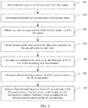
- a transmit power of a node may be monitored and adjusted by using a network device, and the power estimation method provided in this embodiment of the present invention is applied to the network device. Referring to FIG. 1 , the method includes the following steps.
- the first node is a node in the wireless network, for example, the first node may be a base station.
- a transmit power of a first node is a power used by the first node to transmit a signal, where the signal includes a control signal, a service data signal, and the like. In this embodiment, a size of a signal transmit power is discussed, and no limitation is imposed on specific content carried by the signal.
- the network device may obtain the transmit powers of all the first nodes in the N first nodes by querying an internal record or sending query messages to all the first nodes in the N first nodes.
- M is an integer greater than 0, and the second node is a network node that causes interference to at least one first node in the N first nodes; for example, in an application scenario, the first node is a panned node, and the second node is a non-planned node that causes interference to the planned node.
- the transmit power of the second node is limited so as to control the interference caused by the second node to the first node to be within a range.
- a lower transmit power of the second node indicates weaker interference caused by the second node to the first node and worse communication quality of the second node; therefore, an appropriate transmit power needs to be determined for the second node.
- a user service requirement of an n th first node in the N first nodes is a service data rate between the n th first node and a user served by the n th first node.
- the user may be a mobile phone, or may be another mobile data terminal device.
- a user service requirement of the n th first node is a sum of the service data rate of the n th first node and the multiple users served by the n th first node.
- Each first node may provide a service for multiple users at a time.
- the service provided by the first node may be specifically a mobile call, a mobile network, or the like, and different services need to occupy different quantities of physical resources.
- the quantity of physical resources may include information about a timeslot, bandwidth, and the like.
- each of the first nodes in N first nodes collects, within a period of time, statistics about service requirements of all users served by the first node; the network device receives statistical results sent by each of the first nodes in the N first nodes; and a mathematical model of the user service requirement is established according to the statistical results.
- the service requirements of all the users served by each of the first nodes in the N first nodes are obtained by means of estimation by using the mathematical model, the service requirements of the users served by the node are summed so as to obtain a user service requirement of the node.
- An estimated load value of the n th first node in the N first nodes is a value obtained by estimating an actual load value of the n th first node.
- the actual load value of the n th first node in the N first nodes is used to indicate an actual physical resource consumption level of the n th first node
- the estimated load value of the n th first node in the N first nodes is a value obtained by estimating a physical resource consumption level of the n th first node in the N first nodes.
- the transmit powers of all the second nodes in the M second nodes are the transmit powers set in step 102.
- the actual load value of the n th first node in the N first nodes may be specifically a ratio of a quantity of physical resources of the first node that are actually occupied to a total quantity of physical resources that can be provided by the first node.
- the actual load value is greater than or equal to 0, and less than or equal to 1.
- i represents an i th first node
- l represents an l th first node
- q represents a q th second node
- ⁇ i and ⁇ l are respectively estimated load values of the i th first node and the l th first node
- I is a set formed by users served by the N first nodes
- d j is a user service requirement of the user j
- x i,j is equal to 1 or 0, where that x i,j is equal to 1 indicates that the i th first node
- the second formula it may be learned from l ⁇ M O ⁇ i ⁇ that the estimated load value of the i th first node in the N first nodes is related to an estimated load value of another first node except the i th first node in the N first nodes. Therefore, the second formula is applied to all the first nodes in the N first nodes, so as to obtain equations related to the estimated load values of all the first nodes in the N first nodes, and obtain the estimated load values of all the first nodes in the N first nodes by solving the equations.
- An allowed transmit power of an m th second node in the M second nodes is used to indicate that a power used by the m th second node to transmit a signal is required to be less than or equal to the allowed transmit power of the m th second node.
- the transmit powers of all the second nodes in the M second nodes are respectively determined as the allowed transmit powers of all the second nodes in the M second nodes.
- the first threshold is a preset maximum load value of the first node. If the estimated load value of the n th first node in the N first nodes is greater than or equal to the first threshold, the transmit powers of all the second nodes in the M second nodes are reduced to lower the interface caused by the second node to the first node, so as to lower the estimated load value of the first node, so that the estimated load values of all the first nodes in the N first nodes are all less than the first threshold.
- the second threshold is less than the first threshold, and a difference between the first threshold and the second threshold represents a floating range of the estimated load values of all the first nodes in the N first nodes. If the estimated load value of the n th first node in the N first nodes is less than the second threshold, a transmit power of a second node is enhanced so as to improve communication quality of the second node. That the estimated load value of the n th first node in the N first nodes falls within the floating range indicates that on a premise of ensuring communication quality of the first node, the second node achieves the best communication quality.
- the first threshold may be set to a same value, or may be set to different values; optionally, the second threshold may be 90% of the first threshold.
- a specific value of the second threshold may be set according to an actual situation, and the present invention imposes no limitation on the specific value of the second threshold.
- the transmit powers of all the second nodes in the M second nodes are respectively determined as the allowed transmit powers of all the second nodes in the M second nodes.
- the transmit powers of all the second nodes in the M second nodes are reduced so as to lower the estimated load values of all the first nodes in the N first nodes. If the estimated load value of the n th first node in the N first nodes is less than the second threshold, or the transmit power of the m th second node in the M second nodes is less than the third threshold, the transmit powers of all the second nodes in the M second nodes are enhanced so as to improve the communication quality of all the second nodes in the M second nodes. Steps 103 to 105 are cyclically performed so as to adjust the transmit powers of all the second nodes in the M second nodes, and allowed transmit powers for all the second nodes in the M second nodes are finally determined.
- a method for determining a transmit power of a second node is designed only for a single second node, in which estimation is performed on access link quality of at least one first node within a coverage area of the second node, and a transmit power range that is determined for the second node according to an access link with the worst quality is generally relatively low, and consequently communication quality of the second node is poor.
- transmit powers of all first nodes in N first nodes are obtained; user service requirements of all the first nodes in the N first nodes are obtained; transmit powers of all second nodes in M second nodes are set; and estimated load values of all the first nodes in the N first nodes are obtained according to the transmit powers of all the first nodes in the N first nodes, the user service requirements of all the first nodes in the N first nodes, and the transmit powers of all the second nodes in the M second nodes, so as to determine allowed transmit powers of all the second nodes in the M second nodes.
- the power estimation method provided in this embodiment of the present invention takes load values of the N first nodes and transmit powers of the M second nodes into consideration, and ensures that the estimated load values of the first nodes are less than the first threshold, that is, controls interference caused by a second node to a first node to be within a range, and enhances an allowed transmit power of the second node as much as possible, so as to improve the communication quality of the second node.
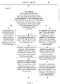
- FIG. 2 Another embodiment of the present invention provides a power estimation method, which is applied to an application scenario shown in FIG. 2 .
- a node A, a node B, and a node C are nodes in a wireless network of an operator.
- the wireless network operator has his own radio spectrum resource, and some spectrum resource demanders rent a spectrum from the operator so as to set up a private wireless network.
- a node D, a node E, a node F, and a node G are nodes in the private wireless network. Because the spectrum is shared, interference exists between the private wireless network node and the operator wireless network node.
- a power estimation method provided in another embodiment of the present invention includes the following steps.
- the first node may be an access point in a wireless network of the operator wireless network, and the access point in the wireless network may be specifically a base station in the wireless network.
- the node A, the node B, and the node C are first nodes.
- the network device may obtain the transmit powers of all the first nodes in the N first nodes by querying an internal record or sending query messages to all the first nodes in the N first nodes.
- the second node is a network node that causes interference to the first node and whose transmit power needs to be limited.
- M is an integer greater than 0.
- the transmit power of the second node is limited so as to control the interference caused by the second node to the first node to be within a range.
- a lower transmit power of the second node indicates weaker interference caused by the second node to the first node and worse communication quality of the second node; therefore, an appropriate transmit power needs to be determined for the second node.
- each of the first nodes in the N first nodes collects, within a period of time, statistics about users served by the first node, and for a user, collects a service requirement of the user.
- the network device receives statistical results from each of the first nodes in the N first nodes; a mathematical model of the user service requirement is established according to the statistical results; the user service requirement is used as a random variable in probability statistics; and the user service requirements of all the first nodes in the N first nodes are estimated by using the mathematical model, so as to obtain the user service requirements of all the first nodes in the N first nodes.
- a channel gain is a ratio of an actual receive power of a user to a transmit power of a node, that is, the actual receive power of the user is a product of the transmit power of the node and the channel gain from the node to the user.
- An n th first node is used as an example.
- a transmit power of the node is P 1
- an actual receive power of the user is P 2
- the channel gains from each of the first nodes and each of the second nodes to each user may be obtained according to user location information of each of the first nodes in the N first nodes and location information of each of the second nodes in the M second nodes, where user location information of one node is used to indicate a distance between a user served by the node and the node.
- the location information may be coordinates of a user location, and a distance between a user and a node serving the user may be determined according to coordinates of a user location.
- statistics collection is performed on the user location information, and a mathematical model of the user location information is established, so as to obtain user location information of all the first nodes in the N first nodes.
- the second node is an access point in the private wireless network
- the network device may obtain location information of all the second nodes in the M second nodes from an operation, administration and maintenance (Operation Administration and Maintenance, OAM) center of the private wireless network.
- OAM Operaation Administration and Maintenance
- the network device proactively sends a message to the operation, administration and maintenance center of the private wireless network, so as to query location information of a private wireless network node in a working state.
- the operation, administration and maintenance center of the private wireless network periodically sends location information of a private wireless network node in a working state to the network device.
- the operation, administration and maintenance center of the private wireless network sends updated location information to the network device.
- the estimated load value is a value obtained by estimating an actual load value.
- An actual load value of the n th first node in the N first nodes is a ratio of a quantity of physical resources of the n th first node that are actually occupied to a total quantity of physical resources that can be provided by the n th first node.
- the estimated load value of the i th first node in the N first nodes is related to an estimated load value of another first node except the i th first node in the N first nodes. Therefore, the first formula is applied to all the first nodes in the N first nodes, so as to obtain equations related to the estimated load values of all the first nodes in the N first nodes, and obtain the estimated load values of all the first nodes in the N first nodes by solving the equations.
- the user location information and the user service requirements of all the first nodes are random variables. Therefore, based on the user location information and the user service requirements of all the first nodes in the N first nodes, the estimated load values of all the first nodes in the N first nodes obtained by using the first formula are also random variables.
- the estimated load values of all the first nodes in the N first nodes are obtained by using the first formula, that is, estimation is preformed once on the estimated load values of all the first nodes in the N first nodes.
- the estimated load values of all the first nodes in the N first nodes may be estimated s times, that is, step 303 to step 305 are cyclically performed s times.
- Estimated load values of all the first nodes in the N first nodes are obtained in a k th estimation in the s estimations, among which a maximum value is used as an estimated load value of the k th estimation.
- Each estimation in the s estimations is an independent event, and estimated load values of all the estimations meet a same probability distribution function F(x), that is, estimated load values of all the estimations in the s estimations are independent and identically distributed random variables.
- s estimated load values obtained in the s estimations are sequenced in ascending order: ⁇ 1, s , ⁇ 2, s , ⁇ 3, s ,... ⁇ k , s , ..., ⁇ s , s .
- An allowed transmit power of an m th second node in the M second nodes is used to indicate that a power used by the m th second node to transmit a signal is required to be less than or equal to the allowed transmit power of the m th second node.
- this embodiment provides two possible implementation manners, which are used to determine the allowed transmit powers of all the second nodes in the M second nodes.
- the transmit powers of all the second nodes in the M second nodes are respectively used as the allowed transmit powers of all the second nodes in the M second nodes, where the second threshold is less than the first threshold.
- the first threshold is a preset maximum estimated load value of the first node; the second threshold is less than the first threshold.
- a difference between the first threshold and the second threshold represents a floating range of the estimated load values of all the first nodes in the N first nodes.
- the transmit powers of all the second nodes in the M second nodes set in step 302 are determined as the allowed transmit powers of all the second nodes in the M second nodes.
- a specific value of the second threshold may be set according to an actual situation, and the present invention imposes no limitation on the specific value of the second threshold.
- ⁇ s s is greater than or equal to the first threshold, it indicates that the overall transmit powers of all the second nodes in the M second nodes set in step 302 are relatively high.
- a preset step is respectively subtracted from the transmit powers of all the second nodes in the M second nodes, so as to obtain new transmit powers of all the second nodes in the M second nodes, and steps are re-performed from step 302.
- a transmit power of the m th second node in the M second nodes is less than or equal to a maximum transmit power of the m th second node.
- Different transmit powers may be set for different second nodes in the M second nodes. Accordingly, for different second nodes, a specific value of the preset step may be different.
- the estimated load value of the n th first node in the N first nodes is less than or equal to the second threshold, indicating that the overall transmit powers set for all the second nodes in the M second nodes set in step 302 are relatively low.
- a preset step is respectively added to the transmit powers of all the second nodes in the M second nodes, so as to obtain new transmit powers of all the second nodes in the M second nodes, and steps are re-performed from step 302.
- ⁇ s s is greater than or equal to the first threshold, it indicates that the overall transmit powers set for all the second nodes in the M second nodes in step 302 are relatively high.
- a preset step is respectively subtracted from the transmit powers of all the second nodes in the M second nodes, so as to obtain new transmit powers of all the second nodes in the M second nodes, and steps are re-performed from step 302.
- the transmit power of the m th second node in the M second nodes is less than or equal to a third threshold, it indicates that the overall transmit powers set for all the second nodes in the M second nodes in step 302 are relatively low.
- a preset step is respectively added to the transmit powers of all the second nodes in the M second nodes, so as to obtain new transmit powers of all the second nodes in the M second nodes, and steps are re-performed from step 302.
- the second implementation manner is described by using a dichotomy as an example.
- the transmit power of the m th second node in the M second nodes is less than or equal to the maximum transmit power of an m th second node.
- the network device obtains maximum transmit powers of all the second nodes in the M second nodes from a network management device of the second node by sending a request to the network management device of the second node, and the maximum transmit power of the m th second node in the M second nodes is set as the transmit power of the m th second node in the M second nodes.
- a preset step is respectively subtracted from the transmit powers of all the second nodes in the M second nodes, so as to obtain new transmit powers of all the second nodes in the M second nodes.
- the preset step is half of a length of a selection interval, where the selection interval is a value range of a preset value set when the transmit powers are set for all the second nodes in the M second nodes.
- the selection interval is a first interval, where the first interval is specifically an interval from 0 to P 1 ; the preset step is specifically ( P 1 -0)/2; a preset step is subtracted from P 1 , so as to obtain new transmit powers P 2 of all the second nodes in the M second nodes, and steps are re-performed from step 302.
- ⁇ s s that is corresponding to P 2 is obtained by means of calculation according to P 2 .
- the transmit powers set for all the second nodes in the M second nodes are P 2
- a second interval is used as the selection interval
- the second interval is an interval from P 2 to P 1 .
- a preset step is respectively added to the transmit powers of all the second nodes in the M second nodes, so as to obtain new transmit powers of all the second nodes in the M second nodes.
- the preset step is half of a length of a selection interval, that is, half of a length of the second interval.
- the preset step is specifically( P 1 - P 2 )/2; a preset step is added to P 2 , so as to obtain new transmit powers P 3 of all the second nodes in the M second nodes, and steps are re-performed from step 302.
- the preset step is gradually reduced by repeatedly performing steps 302 to 306. Specifically and optionally, a difference between a maximum value of the selection interval and an allowed transmit power accuracy is used as the third threshold. Further, optionally, the allowed transmit power accuracy may be set to 5% of the maximum transmit power of the second node, that is, 5% of P 1 .
- the transmit power of the m th second node in the M second nodes is used as an allowed transmit power of the node.
- a relationship between P 1 , P 2 , and P 3 on a number axis is shown as FIG. 5 .
- An interval from 0 to P 1 is the first interval, and an interval from P 2 to P 1 is the second interval; P 2 is the median of the first interval, and P 3 is the median of the second interval.
- new transmit powers are first set for all the second nodes in the M second nodes, where the new transmit power is a median of a selection interval, and ⁇ s , s that is corresponding to the new transmit power is obtained by means of calculation according to the new transmit power.
- the selection interval is constantly narrowed, ⁇ s , s is increasingly approaching the first threshold, and the transmit powers of all the second nodes in the M second nodes are increasingly approaching the third threshold.
- estimated load values of all the first nodes in the N first nodes are all less than a first threshold
- transmit powers of all the second nodes in the M second nodes are all greater than a third threshold.
- the transmit power of the m th second node in the M second nodes is used as an allowed transmit power of the second node.
- the allowed transmit power determined for the m th second node in the M second nodes is greater than the maximum transmit power of the m th second node, it indicates that the m th second node in the M second nodes may operate at the maximum transmit power.
- the preset step is half of a length of the selection interval. New transmit powers of all the second nodes in the M second nodes are obtained by respectively adding or subtracting a preset step to or from the transmit powers of all the second nodes in the M second nodes.
- the preset step may be set to a fixed value. Specifically and optionally, the preset step may be 1% of P 1 , and a specific value of the preset step may be adjusted according to an actual situation. Only an exemplary description is provided herein, and the present invention imposes no limitation on the specific value of the preset step.
- new transmit powers of all the second nodes in the M second nodes are obtained by adding or subtracting a preset step to or from the transmit powers of all the second nodes in the M second nodes, and the allowed transmit powers of all the second nodes in the M second nodes are finally determined.
- the first threshold is a sum of a maximum value in first load values of the N first nodes and a first preset margin, or a product of a maximum value in the first load values of the N first nodes and a first preset coefficient.
- This embodiment provides the following three manners for setting the first threshold, which certainly does not represent that in this embodiment, the first threshold can be set only in the following three manners. Three specific implementation manners are merely listed herein, and the present invention imposes no limitation on a specific manner of setting the first threshold.
- a first setting manner is that a first load value of the n th first node in the N first nodes is a maximum value in actual load values of the n th first node in the N first nodes.
- the actual load value of the n th first node is used to indicate an actual physical resource consumption level of the n th first node.
- statistics collection is performed on actual load values of all the first nodes in the N first nodes, and it is determined that the maximum value in the actual load values of the n th first node in the N first nodes is ⁇ n , where 0 ⁇ n ⁇ N.
- Maximum values in the actual load values of all the first nodes in the N first nodes are respectively ⁇ 1 , ⁇ 2 , ⁇ 3 , ... ⁇ n ..., among which a maximum value is ⁇ max , and a sum of ⁇ max and the first preset margin is used as the first threshold.
- a second setting manner is that a first load value of the n th first node in the N first nodes is an arithmetic average value of actual load values of the n th first node in the N first nodes.
- statistics collection is performed on actual load values of all the first nodes in the N first nodes, and it is determined that an arithmetic average value of the actual load values of the a th first node in the N first nodes is ⁇ a , where 0 ⁇ a ⁇ N.
- Maximum values in the actual load values of all the first nodes in the N first nodes that are obtained by means of statistics collection are respectively determined as: ⁇ 1 , ⁇ 2 , ⁇ 3 , ... ⁇ a ..., among which a maximum value is ⁇ avr , and a product of ⁇ avr and the first preset coefficient is used as the first threshold.
- a first load value of the n th first node in the N first nodes is obtained by performing weighted summation of a maximum value in actual load values of the n th first node in the N first nodes and a predicted load value of the n th first node in the N first nodes. That is, the first threshold is a sum of ⁇ n ⁇ ⁇ 1 and ⁇ f ⁇ ⁇ 2 , where ⁇ n is the maximum value in the actual load values of the n th first node in the N first nodes; ⁇ f is the predicted load value of the n th first node in the N first nodes; ⁇ 1 is a first weighting coefficient; and ⁇ 2 is a second weighting coefficient.
- the predicted load value of the n th first node in the N first nodes is a value obtained by predicting the actual load value of the n th first node. Specifically, statistics collection is performed on actual load values of all the first nodes in the N first nodes; the maximum value ⁇ n in the actual load values of the n th first node in the N first nodes is determined; and the actual load value is predicted according to the statistics collection, so as to obtain the predicted load value ⁇ f of the n th first node in the N first nodes.
- ⁇ 1 is 70%
- ⁇ 2 is 30%.
- the network device may send the allowed transmit power of the m th second node to the m th second node by using the operation, administration and maintenance (Operation Administration and Maintenance, OAM) center of the private wireless network.
- OAM Operaation Administration and Maintenance
- the network device may update the allowed transmit powers of all the second nodes in the M second nodes according to an actual situation, so that all second nodes in the M second nodes adjust the transmit powers according to the actual situation. For example, the network device periodically determines allowed transmit powers for all the second nodes in the M second nodes; or when the communication quality of the second node is poor, the network device is requested to re-determine allowed transmit powers for all the second nodes in the M second nodes; or when a quantity, a location, or a working state of the second node is changed, the network device may determine allowed transmit powers for all the second nodes in the M second nodes.
- a network device determines transmit powers of all second nodes in M second nodes according to estimated load values of all first nodes in N first nodes.
- a specific solution is: obtaining estimated load values of all the first nodes in the N first nodes according to transmit powers and user service requirements of all the first nodes in the N first nodes and the transmit powers of all the second nodes in the M second nodes; determining allowed transmit powers of all the second nodes in the M second nodes; and sending an allowed transmit power of an m th second node in the M second nodes to the m th second node, so that the m th second node controls a transmit power according to the allowed transmit power of the m th second node.
- the transmit powers of the M second nodes are dynamically set to improve the communication quality of the M second nodes is not limited by a change to user distribution of the M second nodes.
- An embodiment of the present invention provides a network device 60, configured to perform methods described in the embodiments corresponding to FIG. 1 and FIG. 3 .
- the network device 60 includes a receiver 601, a processor 602, a memory 603, and a bus 604.
- the receiver 601, the processor 602, and the memory 603 are connected to each other by using the bus 604.
- the receiver 601 is configured to obtain transmit powers of all first nodes in N first nodes.
- the processor 602 is configured to set transmit powers of all second nodes in M second nodes, where the second node is a network node that causes interference to at least one first node in the N first nodes.
- the processor 602 is further configured to obtain user service requirements of all the first nodes in the N first nodes, where a user service requirement of an n th first node in the N first nodes is a service data rate between the n th first node and a user served by the n th first node, and n is a positive integer less than or equal to N.
- the processor 602 is further configured to obtain estimated load values of all the first nodes in the N first nodes according to the transmit powers of all the first nodes in the N first nodes, the user service requirements of all the first nodes in the N first nodes, and the transmit powers of all the second nodes in the M second nodes, where the estimated load value is a value obtained by estimating a physical resource consumption level of the n th first node in the N first nodes.
- the processor 602 is further configured to: when the estimated load values of all the first nodes in the N first nodes are all less than a first threshold and greater than a second threshold, or when the estimated load values of all the first nodes in the N first nodes are all less than the first threshold and the transmit powers of all the second nodes in the M second nodes are all greater than a third threshold, respectively use the transmit powers of all the second nodes in the M second nodes as allowed transmit powers of all the second nodes in the M second nodes.
- the processor 602 is further configured to: when the estimated load value of the n th first node in the N first nodes is greater than or equal to the first threshold, respectively subtract a preset step from the transmit powers of all the second nodes in the M second nodes, so as to obtain new transmit powers of all the second nodes in the M second nodes.
- the processor 602 is further configured to: when the estimated load value of the n th first node in the N first nodes is less than or equal to the second threshold, or when a transmit power of an m th second node in the M second nodes is less than or equal to the third threshold, respectively add a preset step to the transmit powers of all the second nodes in the M second nodes, so as to obtain new transmit powers of all the second nodes in the M second nodes.
- the processor 602 is further configured to obtain channel gains from each of the first nodes and each of the second nodes to each user.
- the processor 602 is further configured to use a sum of a maximum value in first load values of the N first nodes and a first preset margin, or a product of a maximum value in the first load values of the N first nodes and a first preset coefficient as the first threshold.
- a first load value of the n th first node in the N first nodes is a maximum value in actual load values of the n th first node in the N first nodes, where the actual load value of the n th first node is used to indicate an actual physical resource consumption level of the n th first node.
- a first load value of the n th first node in the N first nodes is an arithmetic average value of actual load values of the n th first node in the N first nodes.
- a first load value of the n th first node in the N first nodes is a sum of ⁇ n ⁇ ⁇ 1 and ⁇ f ⁇ ⁇ 2 , where ⁇ n is a maximum value in actual load values of the n th first node in the N first nodes, and ⁇ f is a predicted load value of the n th first node in the N first nodes; the predicted load value of the n th first node in the N first nodes is a value obtained by predicting an actual load value of the n th first node; ⁇ 1 is a first weighting coefficient, and ⁇ 2 is a second weighting coefficient.
- the network device 60 further includes a transmitter 605, configured to send allowed transmit power information of the m th second node in the M second nodes to the m th second node, where the allowed transmit power information is used to indicate an allowed transmit power of the m th second node.
- a transmitter 605 configured to send allowed transmit power information of the m th second node in the M second nodes to the m th second node, where the allowed transmit power information is used to indicate an allowed transmit power of the m th second node.
- the network device provided in this embodiment of the present invention determines transmit powers of all second nodes in M second nodes according to estimated load values of all the first nodes in N first nodes.
- interference caused by the M second nodes to the N first nodes is considered as a whole according to the estimated load values of all the first nodes in the N first nodes, so that transmit powers that are more appropriate are respectively determined for the M second nodes; that is, on a premise of controlling the interference caused by the M second nodes to the N first nodes to be within a range, the transmit powers of the M second nodes are enhanced so as to improve communication quality of the M second nodes.
- the transmit powers of the M second nodes are dynamically set to improve the communication quality of the M second nodes is not limited by a change to user distribution of the M second nodes.
- An embodiment of the present invention provides another network device 70, configured to perform methods described in the embodiments corresponding to FIG. 1 and FIG. 2 .
- the network device 70 includes a receiving unit 701 and a processing unit 702.
- the receiving unit 701 is configured to obtain transmit powers of all first nodes in N first nodes.
- the processing unit 702 is configured to set transmit powers of all second nodes in M second nodes, where the second node is a network node that causes interference to at least one first node in the N first nodes.
- the processing unit 702 is further configured to obtain user service requirements of all the first nodes in the N first nodes, where a user service requirement of an n th first node in the N first nodes is a service data rate between the n th first node and a user served by the n th first node, and n is a positive integer less than or equal to N.
- the processing unit 702 is further configured to obtain estimated load values of all the first nodes in the N first nodes according to the transmit powers of all the first nodes in the N first nodes, the user service requirements of all the first nodes in the N first nodes, and the transmit powers of all the second nodes in the M second nodes, where the estimated load value is a value obtained by estimating a physical resource consumption level of the n th first node in the N first nodes.
- the processing unit 702 is further configured to: when the estimated load values of all the first nodes in the N first nodes are all less than a first threshold and greater than a second threshold, or when the estimated load values of all the first nodes in the N first nodes are all less than the first threshold, and the transmit powers of all the second nodes in the M second nodes are all greater than a third threshold, respectively use the transmit powers of all the second nodes in the M second nodes as allowed transmit powers of all the second nodes in the M second nodes.
- the processing unit 702 is further configured to: when the estimated load value of the n th first node in the N first nodes is greater than or equal to the first threshold, respectively subtract a preset step from the transmit powers of all the second nodes in the M second nodes, so as to obtain new transmit powers of all the second nodes in the M second nodes.
- the processing unit 702 is further configured to: when the estimated load value of the n th first node in the N first nodes is less than or equal to the second threshold, or when a transmit power of an m th second node in the M second nodes is less than or equal to the third threshold, respectively add a preset step to the transmit powers of all the second nodes in the M second nodes, so as to obtain new transmit powers of all the second nodes in the M second nodes.
- processing unit 702 is further configured to obtain channel gains from each of the first nodes and each of the second nodes to each user.
- the processing unit 702 is further configured to use a sum of a maximum value in first load values of the N first nodes and a first preset margin, or a product of a maximum value in the first load values of the N first nodes and a first preset coefficient as the first threshold.
- a first load value of the n th first node in the N first nodes is a maximum value in actual load values of the n th first node in the N first nodes, where the actual load value of the n th first node is used to indicate an actual physical resource consumption level of the n th first node.
- a first load value of the n th first node in the N first nodes is an arithmetic average value of actual load values of the n th first node in the N first nodes.
- a first load value of the n th first node in the N first nodes is a sum of ⁇ n ⁇ ⁇ 1 and ⁇ f ⁇ ⁇ 2 , where ⁇ n is a maximum value in actual load values of the n th first node in the N first nodes, and ⁇ f is a predicted load value of the n th first node in the N first nodes; the predicted load value of the n th first node in the N first nodes is a value obtained by predicting an actual load value of the n th first node; ⁇ 1 is a first weighting coefficient, and ⁇ 2 is a second weighting coefficient.
- the network device 70 further includes a sending unit 703, configured to send allowed transmit power information of the m th second node in the M second nodes to the m th second node, where the allowed transmit power information is used to indicate an allowed transmit power of the m th second node.
- a sending unit 703 configured to send allowed transmit power information of the m th second node in the M second nodes to the m th second node, where the allowed transmit power information is used to indicate an allowed transmit power of the m th second node.
- the network device provided in this embodiment of the present invention determines transmit powers of all second nodes in M second nodes according to estimated load values of all the first nodes in N first nodes.
- interference caused by the M second nodes to the N first nodes is considered as a whole according to the estimated load values of all the first nodes in the N first nodes, so that transmit powers that are more appropriate are respectively determined for the M second nodes; that is, on a premise of controlling the interference caused by the M second nodes to the N first nodes to be within a range, the transmit powers of the M second nodes are enhanced so as to improve communication quality of the M second nodes.
- the transmit powers of the M second nodes are dynamically set to improve the communication quality of the M second nodes is not limited by a change to user distribution of the M second nodes.
- the present invention may be implemented by hardware, firmware or a combination thereof.
- the foregoing functions may be stored in a computer-readable medium or transmitted as one or more instructions or code in the computer-readable medium.
- the computer-readable medium includes a computer storage medium and a communications medium, where the communications medium includes any medium that enables a computer program to be transmitted from one place to another.
- the storage medium may be any available medium accessible to a computer.
- the computer-readable medium may include a RAM (Random Access Memory, random access memory), a ROM (Read-Only Memory, read-only memory), an EEPROM (Electrically Erasable Programmable Read-Only Memory, electrically erasable programmable read-only memory), a CD-ROM (Compact Disc Read-Only Memory, compact disc read-only memory) or other optical disc storage, a disk storage medium or another magnetic storage device, or any other medium that can carry or store expected program code in a form of an instruction or a data structure and can be accessed by a computer.
- any connection may be appropriately defined as a computer-readable medium.
- the coaxial cable, optical fiber/cable, twisted pair, DSL or wireless technologies such as infrared ray, radio and microwave are included in fixation of a medium to which they belong.
- a disk and disc used by the present invention includes a CD (Compact Disc, compact disc), a laser disc, an optical disc, a DVD (Digital Versatile Disc, digital versatile disc), a floppy disk and a Blu-ray disc, where the disk generally copies data by a magnetic means, and the disc copies data optically by a laser means.
- CD Compact Disc, compact disc
- laser disc an optical disc
- DVD Digital Versatile Disc, digital versatile disc
- floppy disk Digital Versatile Disc, digital versatile disc
- Blu-ray disc where the disk generally copies data by a magnetic means, and the disc copies data optically by a laser means.
Landscapes
- Engineering & Computer Science (AREA)
- Computer Networks & Wireless Communication (AREA)
- Signal Processing (AREA)
- Mobile Radio Communication Systems (AREA)
Abstract
Description
- The present invention relates to the communications field, and in particular, to a power estimation method and apparatus.
- With popularization of a wireless network application, a radio spectrum becomes an increasingly scarce resource. In a method in which a spectrum is shared by different wireless networks, a spectrum resource can be more efficiently utilized. However, a problem is that interference exists between the networks that share the spectrum. In practice, some spectrum-resource demanders obtain a spectrum resource by renting the spectrum resource from a spectrum owner, and then construct their respective private wireless networks. Consequently, interference exists between the private wireless network and a network of the spectrum owner, because the spectrum is shared. Generally, a transmit power of a private wireless network node is limited, so as to reduce the interference caused by the private wireless network to the network of the spectrum owner.
- In the prior art, for a node in the private wireless network, within a coverage area of the node, access link quality of at least one node in the spectrum owner network is estimated, and on a premise of ensuring that an access link with the worst quality can normally work, a transmit power of the private wireless network node is determined. In a process of implementing the foregoing method, the inventor finds that in the prior art, a transmit power is determined only for a single node in the private wireless network, without considering overall interference caused by a private wireless network node to a network node of the spectrum owner. In addition, the transmit power that is set for the private wireless network node on the premise of ensuring that the access link with the worst quality can normally work is generally relatively low, which causes a poor communication quality of the private wireless network node.
- Embodiments of the present invention provide a power estimation method and apparatus. Interference caused by a private wireless network node to a spectrum owner network node is considered as a whole, and on a premise of controlling the interference caused by the private wireless network node to the spectrum owner network node to be within a range, a transmit power of the private wireless network node is enhanced so as to improve communication quality of a private wireless network.
- To achieve the foregoing objective, the following technical solutions are used in the embodiments of the present invention.
- According to a first aspect, a power estimation method includes:
- obtaining transmit powers of all first nodes in N first nodes;
- setting transmit powers of all second nodes in M second nodes, where the second node is a network node that causes interference to at least one first node in the N first nodes;
- obtaining user service requirements of all the first nodes in the N first nodes, where a user service requirement of an nth first node in the N first nodes is a service data rate between the nth first node and a user served by the nth first node, and n is a positive integer less than or equal to N;
- obtaining estimated load values of all the first nodes in the N first nodes according to the transmit powers of all the first nodes in the N first nodes, the user service requirements of all the first nodes in the N first nodes, and the transmit powers of all the second nodes in the M second nodes, where the estimated load value is a value obtained by estimating a physical resource consumption level of the nth first node in the N first nodes; and
- if the estimated load values of all the first nodes in the N first nodes are all less than a first threshold and greater than a second threshold, or the estimated load values of all the first nodes in the N first nodes are all less than the first threshold and the transmit powers of all the second nodes in the M second nodes are all greater than a third threshold, respectively using the transmit powers of all the second nodes in the M second nodes as allowed transmit powers of all the second nodes in the M second nodes.
- With reference to the first aspect, in a first possible implementation manner, the method further includes:
- if the estimated load value of the nth first node in the N first nodes is greater than or equal to the first threshold, respectively subtracting a preset step from the transmit powers of all the second nodes in the M second nodes, so as to obtain new transmit powers of all the second nodes in the M second nodes.
- With reference to the first aspect, in a second possible implementation manner, the method further includes:
- if the estimated load value of the nth first node in the N first nodes is less than or equal to the second threshold, or a transmit power of an mth second node in the M second nodes is less than or equal to the third threshold, respectively adding a preset step to the transmit powers of all the second nodes in the M second nodes, so as to obtain new transmit powers of all the second nodes in the M second nodes.
- With reference to the first aspect to the second possible implementation manner of the first aspect, in a third possible implementation manner, the method further includes:
- obtaining channel gains from each of the first nodes and each of the second nodes to each user; where
- the obtaining estimated load values of all the first nodes in the N first nodes according to the transmit powers of all the first nodes in the N first nodes, the user service requirements of all the first nodes in the N first nodes, and the transmit powers of all the second nodes in the M second nodes includes:
- substituting each of the transmit powers of all the first nodes in the N first nodes, the user service requirements of all the first nodes in the N first nodes, and the transmit powers of all second nodes in the M second nodes into a first formula, so as to obtain, by means of calculation, the estimated load value of the nth first node in the N first nodes, where the first formula is:

- where i represents an i th first node; l represents an l th first node; q represents a q th second node; ρi and ρl are respectively estimated load values of the i th first node and the l th first node; I is a set formed by users served by the N first nodes; j represents a user j; dj is a user service requirement of the user j; xi,j is equal to 1 or 0, where that xi,j is equal to 1 indicates that the i th first node provides a service for the user j, and that xi,j is equal to 0 indicates that the i th first node does not provide a service for the user j;

- substituting each of the transmit powers of all the first nodes in the N first nodes, the user service requirements of all the first nodes in the N first nodes, and the transmit powers of all second nodes in the M second nodes into a first formula, so as to obtain, by means of calculation, the estimated load value of the nth first node in the N first nodes, where the first formula is:
- With reference to the first aspect to the third possible implementation manner of the first aspect, in a fourth possible implementation manner,
the first threshold is a sum of a maximum value in first load values of the N first nodes and a first preset margin, or a product of a maximum value in the first load values of the N first nodes and a first preset coefficient; and
a first load value of the nth first node in the N first nodes is a maximum value in actual load values of the nth first node in the N first nodes, where the actual load value of the nth first node is used to indicate an actual physical resource consumption level of the nth first node; or
a first load value of the nth first node in the N first nodes is an arithmetic average value of actual load values of the nth first node in the N first nodes; or
a first load value of the nth first node in the N first nodes is a sum of ρn ×ω 1 and ρf ×ω 2, where ρn is a maximum value in actual load values of the nth first node in the N first nodes, and ρf is a predicted load value of the nth first node in the N first nodes, where the predicted load value of the nth first node in the N first nodes is a value obtained by predicting an actual load value of the nth first node, ω 1 is a first weighting coefficient, and ω 2 is a second weighting coefficient. - With reference to the first aspect to the fourth possible implementation manner of the first aspect, in a fifth possible implementation manner, the method further includes:
- sending allowed transmit power information of the mth second node in the M second nodes to the mth second node, where the allowed transmit power information is used to indicate an allowed transmit power of the mth second node.
- According to a second aspect, a network device includes a receiver, a processor, a memory, and a bus, and the receiver, the processor, and the memory are connected to each other by using the bus, where
the receiver is configured to obtain transmit powers of all first nodes in N first nodes;
the processor is configured to set transmit powers of all second nodes in M second nodes, where the second node is a network node that causes interference to at least one first node in the N first nodes;
the processor is further configured to obtain user service requirements of all the first nodes in the N first nodes, where a user service requirement of an nth first node in the N first nodes is a service data rate between the nth first node and a user served by the nth first node, and n is a positive integer less than or equal to N;
the processor is further configured to obtain estimated load values of all the first nodes in the N first nodes according to the transmit powers of all the first nodes in the N first nodes, the user service requirements of all the first nodes in the N first nodes, and the transmit powers of all the second nodes in the M second nodes, where the estimated load value is a value obtained by estimating a physical resource consumption level of the nth first node in the N first nodes; and
the processor is further configured to: when the estimated load values of all the first nodes in the N first nodes are all less than a first threshold and greater than a second threshold, or when the estimated load values of all the first nodes in the N first nodes are all less than the first threshold, and the transmit powers of all the second nodes in the M second nodes are all greater than a third threshold, respectively use the transmit powers of all the second nodes in the M second nodes as allowed transmit powers of all the second nodes in the M second nodes. - With reference to the second aspect, in a first possible implementation manner,
the processor is further configured to: when the estimated load value of the nth first node in the N first nodes is greater than or equal to the first threshold, respectively subtract a preset step from the transmit powers of all the second nodes in the M second nodes, so as to obtain new transmit powers of all the second nodes in the M second nodes. - With reference to the second aspect, in a second possible implementation manner,
the processor is further configured to: when the estimated load value of the nth first node in the N first nodes is less than or equal to the second threshold, or when a transmit power of an mth second node in the M second nodes is less than or equal to the third threshold, respectively add a preset step to the transmit powers of all the second nodes in the M second nodes, so as to obtain new transmit powers of all the second nodes in the M second nodes. - With reference to the second aspect to the second possible implementation manner of the second aspect, in a third possible implementation manner,
the processor is further configured to obtain channel gains from each of the first nodes and each of the second nodes to each user; and
the processor is further configured to obtain, by means of calculation according to a first formula, the estimated load value of the nth first node in the N first nodes, where the first formula is:

- With reference to the second aspect to the third possible implementation manner of the second aspect, in a fourth possible implementation manner,
the processor is further configured to use a sum of a maximum value in first load values of the N first nodes and a first preset margin, or a product of a maximum value in the first load values of the N first nodes and a first preset coefficient as the first threshold, where
a first load value of the nth first node in the N first nodes is a maximum value in actual load values of the nth first node in the N first nodes, where the actual load value of the nth first node is used to indicate an actual physical resource consumption level of the nth first node; or
a first load value of the nth first node in the N first nodes is an arithmetic average value of actual load values of the nth first node in the N first nodes; or
a first load value of the nth first node in the N first nodes is a sum of ρn ×ω 1 and ρf ×ω 2, where ρn is a maximum value in actual load values of the nth first node in the N first nodes, and ρf is a predicted load value of the nth first node in the N first nodes, where the predicted load value of the nth first node in the N first nodes is a value obtained by predicting an actual load value of the nth first node, ω 1 is a first weighting coefficient, and ω 2 is a second weighting coefficient. - With reference to the second aspect to the fourth possible implementation manner of the second aspect, in a fifth possible implementation manner,
the network device further includes a transmitter, configured to send allowed transmit power information of the mth second node in the M second nodes to the mth second node, where the allowed transmit power information is used to indicate an allowed transmit power of the mth second node. - According to a third aspect, a network device includes a receiving unit and a processing unit, where
the receiving unit is configured to obtain transmit powers of all first nodes in N first nodes;
the processing unit is configured to set transmit powers of all second nodes in M second nodes, where the second node is a network node that causes interference to at least one first node in the N first nodes;
the processing unit is further configured to obtain user service requirements of all the first nodes in the N first nodes, where a user service requirement of an nth first node in the N first nodes is a service data rate between the nth first node and a user served by the nth first node, and n is a positive integer less than or equal to N;
the processing unit is further configured to obtain estimated load values of all the first nodes in the N first nodes according to the transmit powers of all the first nodes in the N first nodes, the user service requirements of all the first nodes in the N first nodes, and the transmit powers of all the second nodes in the M second nodes, where the estimated load value is a value obtained by estimating a physical resource consumption level of the nth first node in the N first nodes; and
the processing unit is further configured to: when the estimated load values of all the first nodes in the N first nodes are all less than a first threshold and greater than a second threshold, or when the estimated load values of all the first nodes in the N first nodes are all less than the first threshold, and the transmit powers of all the second nodes in the M second nodes are all greater than a third threshold, respectively use the transmit powers of all the second nodes in the M second nodes as allowed transmit powers of all the second nodes in the M second nodes. - With reference to the third aspect, in a first possible implementation manner,
the processing unit is further configured to: when the estimated load value of the nth first node in the N first nodes is greater than or equal to the first threshold, respectively subtract a preset step from the transmit powers of all the second nodes in the M second nodes, so as to obtain new transmit powers of all the second nodes in the M second nodes. - With reference to the third aspect, in a second possible implementation manner,
the processing unit is further configured to: when the estimated load value of the nth first node in the N first nodes is less than or equal to the second threshold, or when a transmit power of an mth second node in the M second nodes is less than or equal to the third threshold, respectively add a preset step to the transmit powers of all the second nodes in the M second nodes, so as to obtain new transmit powers of all the second nodes in the M second nodes. - With reference to the third aspect to the second possible implementation manner of the third aspect, in a third possible implementation manner,
the processing unit is further configured to obtain channel gains from each of the first nodes and each of the second nodes to each user; and
the processing unit is further configured to obtain, by means of calculation according to a first formula, the estimated load value of the nth first node in the N first nodes, where the first formula is:

- With reference to the third aspect to the third possible implementation manner of the third aspect, in a fourth possible implementation manner,
the processing unit is further configured to use a sum of a maximum value in first load values of the N first nodes and a first preset margin, or a product of a maximum value in the first load values of the N first nodes and a first preset coefficient as the first threshold, where
a first load value of the nth first node in the N first nodes is a maximum value in actual load values of the nth first node in the N first nodes, where the actual load value of the nth first node is used to indicate an actual physical resource consumption level of the nth first node; or
a first load value of the nth first node in the N first nodes is an arithmetic average value of actual load values of the nth first node in the N first nodes; or
a first load value of the nth first node in the N first nodes is a sum of ρn ×ω 1 and ρf ×ω 2, where ρn is a maximum value in actual load values of the nth first node in the N first nodes, and ρf is a predicted load value of the nth first node in the N first nodes, where the predicted load value of the nth first node in the N first nodes is a value obtained by predicting an actual load value of the nth first node, ω 1 is a first weighting coefficient, and ω 2 is a second weighting coefficient. - With reference to the third aspect to the fourth possible implementation manner of the third aspect, in a fifth possible implementation manner,
the network device further includes a sending unit, configured to send allowed transmit power information of the mth second node in the M second nodes to the mth second node, where the allowed transmit power information is used to indicate an allowed transmit power of the mth second node. - According to the power estimation method and apparatus provided in the embodiments of the present invention, transmit powers of all first nodes in N first nodes are obtained; user service requirements of all the first nodes in the N first nodes are obtained; transmit powers of all second nodes in M second nodes are set; and estimated load values of all the first nodes in the N first nodes are obtained according to the transmit powers of all the first nodes in the N first nodes, the user service requirements of all the first nodes in the N first nodes, and the transmit powers of all the second nodes in the M second nodes, so as to determine allowed transmit powers of all the second nodes in the M second nodes. In an application scenario in which both M and N are integers greater than 1, that is, in an application scenario in which multiple first nodes and multiple second nodes exist, different from the prior art in which a transmit power of a second node is determined for a single second node, the power estimation method provided in the embodiments of the present invention takes interference caused by the M second nodes to the N first nodes into consideration as a whole, and on a premise of ensuring that the estimated load values of the first nodes are less than a first threshold, enhances an allowed transmit power of a second node as much as possible, so as to improve communication quality of the second node. When M is equal to 1, in the power estimation method provided in the embodiments of the present invention, a problem in the prior art that a transmit power that is set for a second node according to access link quality is relatively low is avoided.
- To describe the technical solutions in the embodiments of the present invention or in the prior art more clearly, the following briefly describes the accompanying drawings required for describing the embodiments. Apparently, the accompanying drawings in the following description show merely some embodiments of the present invention, and a person of ordinary skill in the art may still derive other drawings from these accompanying drawings without creative efforts.
-
FIG. 1 is a schematic flowchart of a power estimation method according to an embodiment of the present invention; -
FIG. 2 is a schematic diagram of an application scenario of a power estimation method according to another embodiment of the present invention; -
FIG. 3 is a schematic flowchart of a power estimation method according to another embodiment of the present invention; -
FIG. 4 is a schematic flowchart of a method for determining allowed transmit powers of all second nodes in M second nodes in a power estimation method according to another embodiment of the present invention; -
FIG. 5 is a schematic flowchart of a method for setting transmit powers for all second nodes in M second nodes in a power estimation method according to another embodiment of the present invention; -
FIG. 6 is a schematic structural diagram of a network device according to an embodiment of the present invention; and -
FIG. 7 is a schematic structural diagram of another network device according to an embodiment of the present invention. - The following clearly and completely describes the technical solutions in the embodiments of the present invention with reference to the accompanying drawings in the embodiments of the present invention. Apparently, the described embodiments are merely some but not all of the embodiments of the present invention. All other embodiments obtained by a person of ordinary skill in the art based on the embodiments of the present invention without creative efforts shall fall within the protection scope of the present invention.
- An embodiment of the present invention provides a power estimation method, which is used to limit a transmit power of a wireless network node that generates interference. For example, in a heterogeneous network (HetNet, Heterogeneous Network), some non-planned nodes exist, such as a base station established by renting a spectrum, or an individual wireless access point, such as a home base station. Because there are overlapping parts between spectrums of these non-planned nodes and a planned node deployed by an operator, interference is caused to the panned node. Interference to the planned node may be reduced by appropriately limiting a transmit power of the non-planned node. In this embodiment, interference caused by the second node to a first node is reduced by limiting a transmit power of a second node. Preferably, the first node may be a planned node, and the second node may be a non-planned node. In a wireless network, a transmit power of a node may be monitored and adjusted by using a network device, and the power estimation method provided in this embodiment of the present invention is applied to the network device. Referring to
FIG. 1 , the method includes the following steps. - 101. Obtain transmit powers of all first nodes in N first nodes.
- N is an integer greater than 0. The first node is a node in the wireless network, for example, the first node may be a base station. A transmit power of a first node is a power used by the first node to transmit a signal, where the signal includes a control signal, a service data signal, and the like. In this embodiment, a size of a signal transmit power is discussed, and no limitation is imposed on specific content carried by the signal.
- Optionally, the network device may obtain the transmit powers of all the first nodes in the N first nodes by querying an internal record or sending query messages to all the first nodes in the N first nodes.
- 102. Set transmit powers of all second nodes in M second nodes.
- M is an integer greater than 0, and the second node is a network node that causes interference to at least one first node in the N first nodes; for example, in an application scenario, the first node is a panned node, and the second node is a non-planned node that causes interference to the planned node.
- When the second node causes interference to the first node, the transmit power of the second node is limited so as to control the interference caused by the second node to the first node to be within a range. A lower transmit power of the second node indicates weaker interference caused by the second node to the first node and worse communication quality of the second node; therefore, an appropriate transmit power needs to be determined for the second node.
- 103. Obtain user service requirements of all the first nodes in the N first nodes.
- A user service requirement of an nth first node in the N first nodes is a service data rate between the nth first node and a user served by the nth first node. The user may be a mobile phone, or may be another mobile data terminal device. When the nth first node serves multiple users, a user service requirement of the nth first node is a sum of the service data rate of the nth first node and the multiple users served by the nth first node.
- Each first node may provide a service for multiple users at a time. The service provided by the first node may be specifically a mobile call, a mobile network, or the like, and different services need to occupy different quantities of physical resources. Optionally, the quantity of physical resources may include information about a timeslot, bandwidth, and the like.
- Optionally, each of the first nodes in N first nodes collects, within a period of time, statistics about service requirements of all users served by the first node; the network device receives statistical results sent by each of the first nodes in the N first nodes; and a mathematical model of the user service requirement is established according to the statistical results. The service requirements of all the users served by each of the first nodes in the N first nodes are obtained by means of estimation by using the mathematical model, the service requirements of the users served by the node are summed so as to obtain a user service requirement of the node.
- Optionally, there is no sequence between
steps 101 to 103. - 104. Obtain estimated load values of all the first nodes in the N first nodes according to the transmit powers of all the first nodes in the N first nodes, the user service requirements of all the first nodes in the N first nodes, and the transmit powers of all the second nodes in the M second nodes.
- An estimated load value of the nth first node in the N first nodes is a value obtained by estimating an actual load value of the nth first node. The actual load value of the nth first node in the N first nodes is used to indicate an actual physical resource consumption level of the nth first node, and the estimated load value of the nth first node in the N first nodes is a value obtained by estimating a physical resource consumption level of the nth first node in the N first nodes. The transmit powers of all the second nodes in the M second nodes are the transmit powers set in
step 102. - The actual load value of the nth first node in the N first nodes may be specifically a ratio of a quantity of physical resources of the first node that are actually occupied to a total quantity of physical resources that can be provided by the first node. The actual load value is greater than or equal to 0, and less than or equal to 1. During estimation of a requirement of a user on a physical resource of a first node is estimated, when a quantity of the physical resource requirement estimated is equal to or greater than a total quantity of physical resources that can be provided by the first node, an estimated load value is 1. Optionally, an estimated load value of each of the first nodes in the N first nodes may be calculated by using a second formula, where the second formula is specifically:


- In the second formula, it may be learned from l∈MO \{i} that the estimated load value of the i th first node in the N first nodes is related to an estimated load value of another first node except the i th first node in the N first nodes. Therefore, the second formula is applied to all the first nodes in the N first nodes, so as to obtain equations related to the estimated load values of all the first nodes in the N first nodes, and obtain the estimated load values of all the first nodes in the N first nodes by solving the equations.
- 105. Determine allowed transmit powers of all the second nodes in the M second nodes.
- An allowed transmit power of an mth second node in the M second nodes is used to indicate that a power used by the mth second node to transmit a signal is required to be less than or equal to the allowed transmit power of the mth second node.
- Specifically, in a first application scenario, if the estimated load values of all the first nodes in the N first nodes are all less than a first threshold and greater than a second threshold, the transmit powers of all the second nodes in the M second nodes are respectively determined as the allowed transmit powers of all the second nodes in the M second nodes.
- The first threshold is a preset maximum load value of the first node. If the estimated load value of the nth first node in the N first nodes is greater than or equal to the first threshold, the transmit powers of all the second nodes in the M second nodes are reduced to lower the interface caused by the second node to the first node, so as to lower the estimated load value of the first node, so that the estimated load values of all the first nodes in the N first nodes are all less than the first threshold.
- The second threshold is less than the first threshold, and a difference between the first threshold and the second threshold represents a floating range of the estimated load values of all the first nodes in the N first nodes. If the estimated load value of the nth first node in the N first nodes is less than the second threshold, a transmit power of a second node is enhanced so as to improve communication quality of the second node. That the estimated load value of the nth first node in the N first nodes falls within the floating range indicates that on a premise of ensuring communication quality of the first node, the second node achieves the best communication quality. Optionally, for different first nodes, the first threshold may be set to a same value, or may be set to different values; optionally, the second threshold may be 90% of the first threshold. Certainly, a specific value of the second threshold may be set according to an actual situation, and the present invention imposes no limitation on the specific value of the second threshold.
- Alternatively, in a second application scenario, if the estimated load values of all the first nodes in the N first nodes are all less than a first threshold, and the transmit powers of all the second nodes in the M second nodes are all greater than a third threshold, the transmit powers of all the second nodes in the M second nodes are respectively determined as the allowed transmit powers of all the second nodes in the M second nodes.
- When the transmit powers of all the second nodes in the M second nodes are all greater than the third threshold, communication quality of the mth second node in the M second nodes can meet a preset requirement, so as to ensure normal communication of the mth second node.
- If the estimated load value of the nth first node in the N first nodes is greater than or equal to the first threshold, the transmit powers of all the second nodes in the M second nodes are reduced so as to lower the estimated load values of all the first nodes in the N first nodes. If the estimated load value of the nth first node in the N first nodes is less than the second threshold, or the transmit power of the mth second node in the M second nodes is less than the third threshold, the transmit powers of all the second nodes in the M second nodes are enhanced so as to improve the communication quality of all the second nodes in the M second nodes.
Steps 103 to 105 are cyclically performed so as to adjust the transmit powers of all the second nodes in the M second nodes, and allowed transmit powers for all the second nodes in the M second nodes are finally determined. - In the prior art, a method for determining a transmit power of a second node is designed only for a single second node, in which estimation is performed on access link quality of at least one first node within a coverage area of the second node, and a transmit power range that is determined for the second node according to an access link with the worst quality is generally relatively low, and consequently communication quality of the second node is poor. According to the power estimation method provided in this embodiment of the present invention, transmit powers of all first nodes in N first nodes are obtained; user service requirements of all the first nodes in the N first nodes are obtained; transmit powers of all second nodes in M second nodes are set; and estimated load values of all the first nodes in the N first nodes are obtained according to the transmit powers of all the first nodes in the N first nodes, the user service requirements of all the first nodes in the N first nodes, and the transmit powers of all the second nodes in the M second nodes, so as to determine allowed transmit powers of all the second nodes in the M second nodes. Different from a method in the prior art in which a transmit power of a second node is determined for a single second node, the power estimation method provided in this embodiment of the present invention takes load values of the N first nodes and transmit powers of the M second nodes into consideration, and ensures that the estimated load values of the first nodes are less than the first threshold, that is, controls interference caused by a second node to a first node to be within a range, and enhances an allowed transmit power of the second node as much as possible, so as to improve the communication quality of the second node.
- Another embodiment of the present invention provides a power estimation method, which is applied to an application scenario shown in
FIG. 2 . As shown inFIG. 2 , a node A, a node B, and a node C are nodes in a wireless network of an operator. The wireless network operator has his own radio spectrum resource, and some spectrum resource demanders rent a spectrum from the operator so as to set up a private wireless network. A node D, a node E, a node F, and a node G are nodes in the private wireless network. Because the spectrum is shared, interference exists between the private wireless network node and the operator wireless network node. As shown inFIG. 3 , a power estimation method provided in another embodiment of the present invention includes the following steps. - 301. Obtain transmit powers of all first nodes in N first nodes.
- N is an integer greater than 0, and a transmit power of each of the first nodes in the N first nodes is a power used by the first node to transmit a signal. Optionally, the first node may be an access point in a wireless network of the operator wireless network, and the access point in the wireless network may be specifically a base station in the wireless network. Referring to
FIG. 2 , the node A, the node B, and the node C are first nodes. - Optionally, the network device may obtain the transmit powers of all the first nodes in the N first nodes by querying an internal record or sending query messages to all the first nodes in the N first nodes.
- 302. Set transmit powers of all second nodes in M second nodes.
- The second node is a network node that causes interference to the first node and whose transmit power needs to be limited. M is an integer greater than 0. The transmit power of the second node is limited so as to control the interference caused by the second node to the first node to be within a range. A lower transmit power of the second node indicates weaker interference caused by the second node to the first node and worse communication quality of the second node; therefore, an appropriate transmit power needs to be determined for the second node.
- 303. Obtain user service requirements of all the first nodes in the N first nodes.
- Optionally, each of the first nodes in the N first nodes collects, within a period of time, statistics about users served by the first node, and for a user, collects a service requirement of the user. The network device receives statistical results from each of the first nodes in the N first nodes; a mathematical model of the user service requirement is established according to the statistical results; the user service requirement is used as a random variable in probability statistics; and the user service requirements of all the first nodes in the N first nodes are estimated by using the mathematical model, so as to obtain the user service requirements of all the first nodes in the N first nodes.
- 304. Obtain channel gains from each of the first nodes and each of the second nodes to each user.
- A channel gain is a ratio of an actual receive power of a user to a transmit power of a node, that is, the actual receive power of the user is a product of the transmit power of the node and the channel gain from the node to the user. An nth first node is used as an example. A transmit power of the node is P1, and for a user j served by the node, an actual receive power of the user is P2; a channel gain from the nth first node to the user j is: g=P2/P1, then P2=P1 g.
- A longer distance between a node and a user indicates a lower channel gain from the node to the user. Therefore, the channel gains from each of the first nodes and each of the second nodes to each user may be obtained according to user location information of each of the first nodes in the N first nodes and location information of each of the second nodes in the M second nodes, where user location information of one node is used to indicate a distance between a user served by the node and the node. Specifically, the location information may be coordinates of a user location, and a distance between a user and a node serving the user may be determined according to coordinates of a user location. Optionally, with reference to step 303, statistics collection is performed on the user location information, and a mathematical model of the user location information is established, so as to obtain user location information of all the first nodes in the N first nodes.
- Optionally, with reference to the application scenario shown in
FIG. 2 , the second node is an access point in the private wireless network, and the network device may obtain location information of all the second nodes in the M second nodes from an operation, administration and maintenance (Operation Administration and Maintenance, OAM) center of the private wireless network. Specifically, the network device proactively sends a message to the operation, administration and maintenance center of the private wireless network, so as to query location information of a private wireless network node in a working state. Alternatively, the operation, administration and maintenance center of the private wireless network periodically sends location information of a private wireless network node in a working state to the network device. Alternatively, when location information of a private wireless network node in a working state is updated, the operation, administration and maintenance center of the private wireless network sends updated location information to the network device. - 305. Calculate an estimated load value of an nth first node in the N first nodes according to a first formula.
- The estimated load value is a value obtained by estimating an actual load value. An actual load value of the nth first node in the N first nodes is a ratio of a quantity of physical resources of the nth first node that are actually occupied to a total quantity of physical resources that can be provided by the nth first node.
- Specifically, the transmit powers of all the first nodes in the N first nodes, the user service requirements of all the first nodes in the N first nodes, and the transmit powers of all the second nodes in the M second nodes are substituted into a first formula, so as to obtain, by means of calculation, the estimated load value of the nth first node in the N first nodes, where the first formula is:

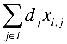
- It may be learned from the first formula that the estimated load value of the i th first node in the N first nodes is related to an estimated load value of another first node except the i th first node in the N first nodes. Therefore, the first formula is applied to all the first nodes in the N first nodes, so as to obtain equations related to the estimated load values of all the first nodes in the N first nodes, and obtain the estimated load values of all the first nodes in the N first nodes by solving the equations.
- With reference to step 303, the user location information and the user service requirements of all the first nodes are random variables. Therefore, based on the user location information and the user service requirements of all the first nodes in the N first nodes, the estimated load values of all the first nodes in the N first nodes obtained by using the first formula are also random variables. The estimated load values of all the first nodes in the N first nodes are obtained by using the first formula, that is, estimation is preformed once on the estimated load values of all the first nodes in the N first nodes.
- To improve accuracy of the estimated load values of all the first nodes in the N first nodes, the estimated load values of all the first nodes in the N first nodes may be estimated s times, that is,
step 303 to step 305 are cyclically performed s times. Estimated load values of all the first nodes in the N first nodes are obtained in a kth estimation in the s estimations, among which a maximum value is used as an estimated load value of the kth estimation. Each estimation in the s estimations is an independent event, and estimated load values of all the estimations meet a same probability distribution function F(x), that is, estimated load values of all the estimations in the s estimations are independent and identically distributed random variables. s estimated load values obtained in the s estimations are sequenced in ascending order: ρ 1,s , ρ 2,s , ρ 3,s ,... ρ k,s , ..., ρ s,s . For a given fraction r:

- 306. Determine allowed transmit powers of all the second nodes in the M second nodes.
- An allowed transmit power of an mth second node in the M second nodes is used to indicate that a power used by the mth second node to transmit a signal is required to be less than or equal to the allowed transmit power of the mth second node.
- Optionally, this embodiment provides two possible implementation manners, which are used to determine the allowed transmit powers of all the second nodes in the M second nodes.
- In a first implementation manner: If the estimated load values of all the first nodes in the N first nodes are all less than a first threshold and greater than a second threshold, the transmit powers of all the second nodes in the M second nodes are respectively used as the allowed transmit powers of all the second nodes in the M second nodes, where the second threshold is less than the first threshold.
- The first threshold is a preset maximum estimated load value of the first node; the second threshold is less than the first threshold. A difference between the first threshold and the second threshold represents a floating range of the estimated load values of all the first nodes in the N first nodes. When ρ s,s is less than the first threshold, and the estimated load values of all the first nodes in the N first nodes are all greater than the second threshold, the transmit powers of all the second nodes in the M second nodes set in
step 302 are determined as the allowed transmit powers of all the second nodes in the M second nodes. Optionally, the second threshold may be 90% of the first threshold. If the estimated load values of all the first nodes in the N first nodes are all greater than 90% of the first threshold and less than the first threshold, the transmit powers of all the second nodes in the M second nodes set instep 302 are determined as the allowed transmit powers of all the second nodes in the M second nodes. Certainly, a specific value of the second threshold may be set according to an actual situation, and the present invention imposes no limitation on the specific value of the second threshold. - If ρ s,s is greater than or equal to the first threshold, it indicates that the overall transmit powers of all the second nodes in the M second nodes set in
step 302 are relatively high. In this case, a preset step is respectively subtracted from the transmit powers of all the second nodes in the M second nodes, so as to obtain new transmit powers of all the second nodes in the M second nodes, and steps are re-performed fromstep 302. With reference to step 302, a transmit power of the mth second node in the M second nodes is less than or equal to a maximum transmit power of the mth second node. Different transmit powers may be set for different second nodes in the M second nodes. Accordingly, for different second nodes, a specific value of the preset step may be different. - Alternatively, the estimated load value of the nth first node in the N first nodes is less than or equal to the second threshold, indicating that the overall transmit powers set for all the second nodes in the M second nodes set in
step 302 are relatively low. In this case, a preset step is respectively added to the transmit powers of all the second nodes in the M second nodes, so as to obtain new transmit powers of all the second nodes in the M second nodes, and steps are re-performed fromstep 302. - In a second implementation manner: If the estimated load values of all the first nodes in the N first nodes are all less than a first threshold and the transmit powers of all the second nodes in the M second nodes are all greater than a third threshold, the transmit powers of all the second nodes in the M second nodes are respectively used as the allowed transmit powers of all the second nodes in the M second nodes.
- If ρ s,s is greater than or equal to the first threshold, it indicates that the overall transmit powers set for all the second nodes in the M second nodes in
step 302 are relatively high. In this case, a preset step is respectively subtracted from the transmit powers of all the second nodes in the M second nodes, so as to obtain new transmit powers of all the second nodes in the M second nodes, and steps are re-performed fromstep 302. - If the transmit power of the mth second node in the M second nodes is less than or equal to a third threshold, it indicates that the overall transmit powers set for all the second nodes in the M second nodes in
step 302 are relatively low. In this case, a preset step is respectively added to the transmit powers of all the second nodes in the M second nodes, so as to obtain new transmit powers of all the second nodes in the M second nodes, and steps are re-performed fromstep 302. - Specifically, referring to a process of determining the allowed transmit powers of all the second nodes in the M second nodes shown in
FIG. 4 , the second implementation manner is described by using a dichotomy as an example. - With reference to step 302, optionally, the transmit power of the mth second node in the M second nodes is less than or equal to the maximum transmit power of an mth second node. Specifically and optionally, the network device obtains maximum transmit powers of all the second nodes in the M second nodes from a network management device of the second node by sending a request to the network management device of the second node, and the maximum transmit power of the mth second node in the M second nodes is set as the transmit power of the mth second node in the M second nodes.
- A case in which maximum transmit powers of all the second nodes in the M second nodes are all P 1 is used as an example herein. The process of determining the allowed transmit powers of all the second nodes in the M second nodes is described. With reference to step 302 to step 305, ρ s,s is obtained by means of calculation according to P 1.
- Optionally, in a specific application scenario, when ρ s,s that is corresponding to P 1 is greater than the first threshold, a preset step is respectively subtracted from the transmit powers of all the second nodes in the M second nodes, so as to obtain new transmit powers of all the second nodes in the M second nodes. The preset step is half of a length of a selection interval, where the selection interval is a value range of a preset value set when the transmit powers are set for all the second nodes in the M second nodes. In this case, the selection interval is a first interval, where the first interval is specifically an interval from 0 to P 1; the preset step is specifically (P 1-0)/2; a preset step is subtracted from P 1, so as to obtain new transmit powers P 2 of all the second nodes in the M second nodes, and steps are re-performed from
step 302. With reference to step 302 to step 305, ρ s,s that is corresponding to P 2 is obtained by means of calculation according to P 2. P 2 is a median of the first interval, and specifically, P 2 =(0+ P 1)/2. - Optionally, when the transmit powers set for all the second nodes in the M second nodes are P 2, and if the transmit power of the mth second node in the M second nodes is less than or equal to the third threshold, it indicates that P 2 is relatively low. In this case, a second interval is used as the selection interval, and the second interval is an interval from P 2 to P 1. A preset step is respectively added to the transmit powers of all the second nodes in the M second nodes, so as to obtain new transmit powers of all the second nodes in the M second nodes. Optionally, the preset step is half of a length of a selection interval, that is, half of a length of the second interval. In this case, the preset step is specifically(P 1 - P 2)/2; a preset step is added to P 2, so as to obtain new transmit powers P 3 of all the second nodes in the M second nodes, and steps are re-performed from
step 302. P 3 is a median of the second interval, and specifically, P 3 =(P 1+P 2)/2. By means of such cyclic operations, the preset step is gradually reduced by repeatedly performingsteps 302 to 306. Specifically and optionally, a difference between a maximum value of the selection interval and an allowed transmit power accuracy is used as the third threshold. Further, optionally, the allowed transmit power accuracy may be set to 5% of the maximum transmit power of the second node, that is, 5% of P 1. When the preset step is less than or equal to a preset length of the allowed transmit power accuracy, and the transmit powers of all the second nodes in the M second nodes are all greater the third threshold, the transmit power of the mth second node in the M second nodes is used as an allowed transmit power of the node. A relationship between P 1, P 2, and P 3 on a number axis is shown asFIG. 5 . An interval from 0 to P 1 is the first interval, and an interval from P 2 to P 1 is the second interval; P 2 is the median of the first interval, and P 3 is the median of the second interval. - In the process of determining the allowed transmit power of the mth second node in the M second nodes by using the dichotomy, new transmit powers are first set for all the second nodes in the M second nodes, where the new transmit power is a median of a selection interval, and ρ s,s that is corresponding to the new transmit power is obtained by means of calculation according to the new transmit power. By cyclically performing
steps 302 to 306, the selection interval is constantly narrowed, ρ s,s is increasingly approaching the first threshold, and the transmit powers of all the second nodes in the M second nodes are increasingly approaching the third threshold. Consequently, estimated load values of all the first nodes in the N first nodes are all less than a first threshold, and transmit powers of all the second nodes in the M second nodes are all greater than a third threshold. In this case, the transmit power of the mth second node in the M second nodes is used as an allowed transmit power of the second node. - If the allowed transmit power determined for the mth second node in the M second nodes is greater than the maximum transmit power of the mth second node, it indicates that the mth second node in the M second nodes may operate at the maximum transmit power.
- In the process of determining the allowed transmit power of the mth second node in the M second nodes by using the dichotomy, the preset step is half of a length of the selection interval. New transmit powers of all the second nodes in the M second nodes are obtained by respectively adding or subtracting a preset step to or from the transmit powers of all the second nodes in the M second nodes. Optionally, the preset step may be set to a fixed value. Specifically and optionally, the preset step may be 1% of P 1, and a specific value of the preset step may be adjusted according to an actual situation. Only an exemplary description is provided herein, and the present invention imposes no limitation on the specific value of the preset step. In a case in which the preset step is fixed, with reference to
steps 302 to 306, new transmit powers of all the second nodes in the M second nodes are obtained by adding or subtracting a preset step to or from the transmit powers of all the second nodes in the M second nodes, and the allowed transmit powers of all the second nodes in the M second nodes are finally determined. - With reference to the process of determining the allowed transmit power of the mth second node in the M second nodes, a description of setting the first threshold is performed herein. Optionally, the first threshold is a sum of a maximum value in first load values of the N first nodes and a first preset margin, or a product of a maximum value in the first load values of the N first nodes and a first preset coefficient. This embodiment provides the following three manners for setting the first threshold, which certainly does not represent that in this embodiment, the first threshold can be set only in the following three manners. Three specific implementation manners are merely listed herein, and the present invention imposes no limitation on a specific manner of setting the first threshold.
- A first setting manner is that a first load value of the nth first node in the N first nodes is a maximum value in actual load values of the nth first node in the N first nodes. The actual load value of the nth first node is used to indicate an actual physical resource consumption level of the nth first node. Specifically, statistics collection is performed on actual load values of all the first nodes in the N first nodes, and it is determined that the maximum value in the actual load values of the nth first node in the N first nodes is ρn , where 0≤n≤N. Maximum values in the actual load values of all the first nodes in the N first nodes are respectively ρ 1, ρ 2, ρ 3, ... ρn ..., among which a maximum value is ρ max, and a sum of ρ max and the first preset margin is used as the first threshold.
- A second setting manner is that a first load value of the nth first node in the N first nodes is an arithmetic average value of actual load values of the nth first node in the N first nodes. Specifically, statistics collection is performed on actual load values of all the first nodes in the N first nodes, and it is determined that an arithmetic average value of the actual load values of the ath first node in the N first nodes is ρ a, where 0≤a≤N. Maximum values in the actual load values of all the first nodes in the N first nodes that are obtained by means of statistics collection are respectively determined as: ρ 1, ρ 2 , ρ 3, ... ρa ..., among which a maximum value is ρavr , and a product of ρavr and the first preset coefficient is used as the first threshold.
- Alternatively, a first load value of the nth first node in the N first nodes is obtained by performing weighted summation of a maximum value in actual load values of the nth first node in the N first nodes and a predicted load value of the nth first node in the N first nodes. That is, the first threshold is a sum of ρn ×ω 1 and ρf ×ω 2, where ρn is the maximum value in the actual load values of the nth first node in the N first nodes; ρf is the predicted load value of the nth first node in the N first nodes; ω 1 is a first weighting coefficient; and ω 2 is a second weighting coefficient. The predicted load value of the nth first node in the N first nodes is a value obtained by predicting the actual load value of the nth first node. Specifically, statistics collection is performed on actual load values of all the first nodes in the N first nodes; the maximum value ρn in the actual load values of the nth first node in the N first nodes is determined; and the actual load value is predicted according to the statistics collection, so as to obtain the predicted load value ρf of the nth first node in the N first nodes. Weighted summation of ρn and ρf is performed so as to obtain ρfn , that is, ρfn = ρn ×ω 1+ ρf ×ω 2, where 0≤n≤N and 0≤f≤N. All first nodes in the N first nodes respectively obtains: ρ f1, ρ f2, ρ f3, ... ρfn ..., among which a maximum value is ρfore , and a sum of ρfore and the first preset margin is used as the first threshold. Optionally, in a specific application scenario, ω 1 is 70%, and ω 2 is 30%.
- 307. Send allowed transmit power information of an mth second node in the M second nodes to the mth second node, where the allowed transmit power information is used to indicate an allowed transmit power of the mth second node.
- Optionally, the mth second node in the M second nodes is an access point in the private wireless network, the network device may send the allowed transmit power of the mth second node to the mth second node by using the operation, administration and maintenance (Operation Administration and Maintenance, OAM) center of the private wireless network.
- Optionally, the network device may update the allowed transmit powers of all the second nodes in the M second nodes according to an actual situation, so that all second nodes in the M second nodes adjust the transmit powers according to the actual situation. For example, the network device periodically determines allowed transmit powers for all the second nodes in the M second nodes; or when the communication quality of the second node is poor, the network device is requested to re-determine allowed transmit powers for all the second nodes in the M second nodes; or when a quantity, a location, or a working state of the second node is changed, the network device may determine allowed transmit powers for all the second nodes in the M second nodes.
- In the power estimation method provided in this embodiment of the present invention, a network device determines transmit powers of all second nodes in M second nodes according to estimated load values of all first nodes in N first nodes. A specific solution is: obtaining estimated load values of all the first nodes in the N first nodes according to transmit powers and user service requirements of all the first nodes in the N first nodes and the transmit powers of all the second nodes in the M second nodes; determining allowed transmit powers of all the second nodes in the M second nodes; and sending an allowed transmit power of an mth second node in the M second nodes to the mth second node, so that the mth second node controls a transmit power according to the allowed transmit power of the mth second node. Compared with a method in the prior art in which a transmit power of the second node is determined for one second node, in this embodiment of the present invention, estimated load values of all the first nodes in the N first nodes, interference caused by the M second nodes to the N first nodes is considered as a whole according to the estimated load values of all the first nodes in the N first nodes, so that transmit powers that are more appropriate are respectively determined for the M second nodes; that is, on a premise of controlling the interference caused by the M second nodes to the N first nodes to be within a range, the transmit powers of the M second nodes are enhanced so as to improve communication quality of the M second nodes. In addition, when load estimation is performed on the N first nodes, a case in which the M second nodes are fully loaded is considered as a whole. Therefore, that the transmit powers of the M second nodes are dynamically set to improve the communication quality of the M second nodes is not limited by a change to user distribution of the M second nodes.
- An embodiment of the present invention provides a
network device 60, configured to perform methods described in the embodiments corresponding toFIG. 1 andFIG. 3 . Referring toFIG. 6 , thenetwork device 60 includes areceiver 601, aprocessor 602, amemory 603, and abus 604. Thereceiver 601, theprocessor 602, and thememory 603 are connected to each other by using thebus 604. - The
receiver 601 is configured to obtain transmit powers of all first nodes in N first nodes. - The
processor 602 is configured to set transmit powers of all second nodes in M second nodes, where the second node is a network node that causes interference to at least one first node in the N first nodes. - The
processor 602 is further configured to obtain user service requirements of all the first nodes in the N first nodes, where a user service requirement of an nth first node in the N first nodes is a service data rate between the nth first node and a user served by the nth first node, and n is a positive integer less than or equal to N. - The
processor 602 is further configured to obtain estimated load values of all the first nodes in the N first nodes according to the transmit powers of all the first nodes in the N first nodes, the user service requirements of all the first nodes in the N first nodes, and the transmit powers of all the second nodes in the M second nodes, where the estimated load value is a value obtained by estimating a physical resource consumption level of the nth first node in the N first nodes. - The
processor 602 is further configured to: when the estimated load values of all the first nodes in the N first nodes are all less than a first threshold and greater than a second threshold, or when the estimated load values of all the first nodes in the N first nodes are all less than the first threshold and the transmit powers of all the second nodes in the M second nodes are all greater than a third threshold, respectively use the transmit powers of all the second nodes in the M second nodes as allowed transmit powers of all the second nodes in the M second nodes. - Optionally, the
processor 602 is further configured to: when the estimated load value of the nth first node in the N first nodes is greater than or equal to the first threshold, respectively subtract a preset step from the transmit powers of all the second nodes in the M second nodes, so as to obtain new transmit powers of all the second nodes in the M second nodes. - Optionally, the
processor 602 is further configured to: when the estimated load value of the nth first node in the N first nodes is less than or equal to the second threshold, or when a transmit power of an mth second node in the M second nodes is less than or equal to the third threshold, respectively add a preset step to the transmit powers of all the second nodes in the M second nodes, so as to obtain new transmit powers of all the second nodes in the M second nodes. - Optionally, the
processor 602 is further configured to obtain channel gains from each of the first nodes and each of the second nodes to each user. - The processor 602 is further configured to obtain, by means of calculation according to a first formula, the estimated load value of the nth first node in the N first nodes, where the first formula is:


- Optionally, the
processor 602 is further configured to use a sum of a maximum value in first load values of the N first nodes and a first preset margin, or a product of a maximum value in the first load values of the N first nodes and a first preset coefficient as the first threshold. - A first load value of the nth first node in the N first nodes is a maximum value in actual load values of the nth first node in the N first nodes, where the actual load value of the nth first node is used to indicate an actual physical resource consumption level of the nth first node.
- Alternatively, a first load value of the nth first node in the N first nodes is an arithmetic average value of actual load values of the nth first node in the N first nodes.
- Alternatively, a first load value of the nth first node in the N first nodes is a sum of ρn ×ω 1 and ρf ×ω 2, where ρn is a maximum value in actual load values of the nth first node in the N first nodes, and ρf is a predicted load value of the nth first node in the N first nodes; the predicted load value of the nth first node in the N first nodes is a value obtained by predicting an actual load value of the nth first node; ω 1 is a first weighting coefficient, and ω 2 is a second weighting coefficient.
- Optionally, the
network device 60 further includes atransmitter 605, configured to send allowed transmit power information of the mth second node in the M second nodes to the mth second node, where the allowed transmit power information is used to indicate an allowed transmit power of the mth second node. - The network device provided in this embodiment of the present invention determines transmit powers of all second nodes in M second nodes according to estimated load values of all the first nodes in N first nodes. Compared with a method in the prior art in which a transmit power of the second node is determined for one second node, in this embodiment of the present invention, interference caused by the M second nodes to the N first nodes is considered as a whole according to the estimated load values of all the first nodes in the N first nodes, so that transmit powers that are more appropriate are respectively determined for the M second nodes; that is, on a premise of controlling the interference caused by the M second nodes to the N first nodes to be within a range, the transmit powers of the M second nodes are enhanced so as to improve communication quality of the M second nodes. In addition, when load estimation is performed on the N first nodes, a case in which the M second nodes are fully loaded is considered as a whole. Therefore, that the transmit powers of the M second nodes are dynamically set to improve the communication quality of the M second nodes is not limited by a change to user distribution of the M second nodes.
- An embodiment of the present invention provides another
network device 70, configured to perform methods described in the embodiments corresponding toFIG. 1 andFIG. 2 . Referring toFIG. 7 , thenetwork device 70 includes a receivingunit 701 and aprocessing unit 702. - The receiving
unit 701 is configured to obtain transmit powers of all first nodes in N first nodes. - The
processing unit 702 is configured to set transmit powers of all second nodes in M second nodes, where the second node is a network node that causes interference to at least one first node in the N first nodes. - The
processing unit 702 is further configured to obtain user service requirements of all the first nodes in the N first nodes, where a user service requirement of an nth first node in the N first nodes is a service data rate between the nth first node and a user served by the nth first node, and n is a positive integer less than or equal to N. - The
processing unit 702 is further configured to obtain estimated load values of all the first nodes in the N first nodes according to the transmit powers of all the first nodes in the N first nodes, the user service requirements of all the first nodes in the N first nodes, and the transmit powers of all the second nodes in the M second nodes, where the estimated load value is a value obtained by estimating a physical resource consumption level of the nth first node in the N first nodes. - The
processing unit 702 is further configured to: when the estimated load values of all the first nodes in the N first nodes are all less than a first threshold and greater than a second threshold, or when the estimated load values of all the first nodes in the N first nodes are all less than the first threshold, and the transmit powers of all the second nodes in the M second nodes are all greater than a third threshold, respectively use the transmit powers of all the second nodes in the M second nodes as allowed transmit powers of all the second nodes in the M second nodes. - Optionally, the
processing unit 702 is further configured to: when the estimated load value of the nth first node in the N first nodes is greater than or equal to the first threshold, respectively subtract a preset step from the transmit powers of all the second nodes in the M second nodes, so as to obtain new transmit powers of all the second nodes in the M second nodes. - Optionally, the
processing unit 702 is further configured to: when the estimated load value of the nth first node in the N first nodes is less than or equal to the second threshold, or when a transmit power of an mth second node in the M second nodes is less than or equal to the third threshold, respectively add a preset step to the transmit powers of all the second nodes in the M second nodes, so as to obtain new transmit powers of all the second nodes in the M second nodes. - Optionally, the
processing unit 702 is further configured to obtain channel gains from each of the first nodes and each of the second nodes to each user. - The processing unit 702 is further configured to obtain, by means of calculation according to a first formula, the estimated load value of the nth first node in the N first nodes, where the first formula is:


- Optionally, the
processing unit 702 is further configured to use a sum of a maximum value in first load values of the N first nodes and a first preset margin, or a product of a maximum value in the first load values of the N first nodes and a first preset coefficient as the first threshold. - A first load value of the nth first node in the N first nodes is a maximum value in actual load values of the nth first node in the N first nodes, where the actual load value of the nth first node is used to indicate an actual physical resource consumption level of the nth first node.
- Alternatively, a first load value of the nth first node in the N first nodes is an arithmetic average value of actual load values of the nth first node in the N first nodes.
- Alternatively, a first load value of the nth first node in the N first nodes is a sum of ρn ×ω 1 and ρf ×ω 2, where ρn is a maximum value in actual load values of the nth first node in the N first nodes, and ρf is a predicted load value of the nth first node in the N first nodes; the predicted load value of the nth first node in the N first nodes is a value obtained by predicting an actual load value of the nth first node; ω 1 is a first weighting coefficient, and ω 2 is a second weighting coefficient.
- Optionally, the
network device 70 further includes a sendingunit 703, configured to send allowed transmit power information of the mth second node in the M second nodes to the mth second node, where the allowed transmit power information is used to indicate an allowed transmit power of the mth second node. - The network device provided in this embodiment of the present invention determines transmit powers of all second nodes in M second nodes according to estimated load values of all the first nodes in N first nodes. Compared with a method in the prior art in which a transmit power of the second node is determined for one second node, in this embodiment of the present invention, interference caused by the M second nodes to the N first nodes is considered as a whole according to the estimated load values of all the first nodes in the N first nodes, so that transmit powers that are more appropriate are respectively determined for the M second nodes; that is, on a premise of controlling the interference caused by the M second nodes to the N first nodes to be within a range, the transmit powers of the M second nodes are enhanced so as to improve communication quality of the M second nodes. In addition, when load estimation is performed on the N first nodes, a case in which the M second nodes are fully loaded is considered as a whole. Therefore, that the transmit powers of the M second nodes are dynamically set to improve the communication quality of the M second nodes is not limited by a change to user distribution of the M second nodes.
- With descriptions of the foregoing embodiments, a person skilled in the art may clearly understand that the present invention may be implemented by hardware, firmware or a combination thereof. When the present invention is implemented by software, the foregoing functions may be stored in a computer-readable medium or transmitted as one or more instructions or code in the computer-readable medium. The computer-readable medium includes a computer storage medium and a communications medium, where the communications medium includes any medium that enables a computer program to be transmitted from one place to another. The storage medium may be any available medium accessible to a computer. The following provides an example but does not impose a limitation: The computer-readable medium may include a RAM (Random Access Memory, random access memory), a ROM (Read-Only Memory, read-only memory), an EEPROM (Electrically Erasable Programmable Read-Only Memory, electrically erasable programmable read-only memory), a CD-ROM (Compact Disc Read-Only Memory, compact disc read-only memory) or other optical disc storage, a disk storage medium or another magnetic storage device, or any other medium that can carry or store expected program code in a form of an instruction or a data structure and can be accessed by a computer. In addition, any connection may be appropriately defined as a computer-readable medium. For example, if software is transmitted from a website, a server or another remote source by using a coaxial cable, an optical fiber/cable, a twisted pair, a DSL (Digital Subscriber Line, digital subscriber line) or wireless technologies such as infrared ray, radio and microwave, the coaxial cable, optical fiber/cable, twisted pair, DSL or wireless technologies such as infrared ray, radio and microwave are included in fixation of a medium to which they belong. For example, a disk and disc used by the present invention includes a CD (Compact Disc, compact disc), a laser disc, an optical disc, a DVD (Digital Versatile Disc, digital versatile disc), a floppy disk and a Blu-ray disc, where the disk generally copies data by a magnetic means, and the disc copies data optically by a laser means. The foregoing combination should also be included in the protection scope of the computer-readable medium.
- The foregoing descriptions are merely specific implementation manners of the present invention, but are not intended to limit the protection scope of the present invention. Any variation or replacement readily figured out by a person skilled in the art within the technical scope disclosed in the present invention shall fall within the protection scope of the present invention. Therefore, the protection scope of the present invention shall be subject to the protection scope of the claims.
Claims (18)
- A power estimation method, comprising:obtaining transmit powers of all first nodes in N first nodes;setting transmit powers of all second nodes in M second nodes, wherein the second node is a network node that causes interference to at least one first node in the N first nodes;obtaining user service requirements of all the first nodes in the N first nodes, wherein a user service requirement of an nth first node in the N first nodes is a service data rate between the nth first node and a user served by the nth first node, and n is a positive integer less than or equal to N;obtaining estimated load values of all the first nodes in the N first nodes according to the transmit powers of all the first nodes in the N first nodes, the user service requirements of all the first nodes in the N first nodes, and the transmit powers of all the second nodes in the M second nodes, wherein an estimated load value of the nth first node in the N first nodes is a value obtained by estimating a physical resource consumption level of the nth first node in the N first nodes; andif the estimated load values of all the first nodes in the N first nodes are all less than a first threshold and greater than a second threshold, or the estimated load values of all the first nodes in the N first nodes are all less than the first threshold and the transmit powers of all the second nodes in the M second nodes are all greater than a third threshold, respectively using the transmit powers of all the second nodes in the M second nodes as allowed transmit powers of all the second nodes in the M second nodes.
- The method according to claim 1, wherein the method further comprises:if the estimated load value of the nth first node in the N first nodes is greater than or equal to the first threshold, respectively subtracting a preset step from the transmit powers of all the second nodes in the M second nodes, so as to obtain new transmit powers of all the second nodes in the M second nodes.
- The method according to claim 1, wherein the method further comprises:if the estimated load value of the nth first node in the N first nodes is less than or equal to the second threshold, or a transmit power of an mth second node in the M second nodes is less than or equal to the third threshold, respectively adding a preset step to the transmit powers of all the second nodes in the M second nodes, so as to obtain new transmit powers of all the second nodes in the M second nodes.
- The method according to any one of claims 1 to 3, wherein the method further comprises:obtaining channel gains from each of the first nodes and each of the second nodes to each user; whereinthe obtaining estimated load values of all the first nodes in the N first nodes according to the transmit powers of all the first nodes in the N first nodes, the user service requirements of all the first nodes in the N first nodes, and the transmit powers of all the second nodes in the M second nodes comprises:substituting each of the transmit powers of all the first nodes in the N first nodes, the user service requirements of all the first nodes in the N first nodes, and the transmit powers of all second nodes in the M second nodes into a first formula, so as to obtain, by means of calculation, the estimated load value of the nth first node in the N first nodes, wherein the first formula is:
 wherein i represents an i th first node; l represents an l th first node; q represents a q th second node; ρi and ρl are respectively estimated load values of the i th first node and the l th first node; I is a set formed by users served by the N first nodes, j represents a user j; dj is a user service requirement of the user j; xi,j is equal to 1 or 0, wherein that xi,j is equal to 1 indicates that the i th first node provides a service for the user j, and that xi,j is equal to 0 indicates that the i th first node does not provide a service for the user j;
- The method according to any one of claims 1 to 4, wherein:the first threshold is a sum of a maximum value in first load values of the N first nodes and a first preset margin, or a product of a maximum value in the first load values of the N first nodes and a first preset coefficient; anda first load value of the nth first node in the N first nodes is a maximum value in actual load values of the nth first node in the N first nodes, wherein the actual load value of the nth first node is used to indicate an actual physical resource consumption level of the nth first node; ora first load value of the nth first node in the N first nodes is an arithmetic average value of actual load values of the nth first node in the N first nodes; ora first load value of the nth first node in the N first nodes is a sum of ρn ×ω 1 and ρf ×ω 2, wherein ρn is a maximum value in actual load values of the nth first node in the N first nodes, and ρf is a predicted load value of the nth first node in the N first nodes, wherein the predicted load value of the nth first node in the N first nodes is a value obtained by predicting an actual load value of the nth first node, ω 1 is a first weighting coefficient, and ω 2 is a second weighting coefficient.
- The method according to any one of claims 1 to 5, wherein the method further comprises:sending allowed transmit power information of the mth second node in the M second nodes to the mth second node, wherein the allowed transmit power information is used to indicate an allowed transmit power of the mth second node.
- A network device, wherein the network device comprises: a receiver, a processor, a memory, and a bus, and the receiver, the processor, and the memory are connected to each other by using the bus, wherein:the receiver is configured to obtain transmit powers of all first nodes in N first nodes;the processor is configured to set transmit powers of all second nodes in M second nodes, wherein the second node is a network node that causes interference to at least one first node in the N first nodes;the processor is further configured to obtain user service requirements of all the first nodes in the N first nodes, wherein a user service requirement of an nth first node in the N first nodes is a service data rate between the nth first node and a user served by the nth first node, and n is a positive integer less than or equal to N;the processor is further configured to obtain estimated load values of all the first nodes in the N first nodes according to the transmit powers of all the first nodes in the N first nodes, the user service requirements of all the first nodes in the N first nodes, and the transmit powers of all the second nodes in the M second nodes, wherein the estimated load value is a value obtained by estimating a physical resource consumption level of the nth first node in the N first nodes; andthe processor is further configured to: when the estimated load values of all the first nodes in the N first nodes are all less than a first threshold and greater than a second threshold, or when the estimated load values of all the first nodes in the N first nodes are all less than the first threshold and the transmit powers of all the second nodes in the M second nodes are all greater than a third threshold, respectively use the transmit powers of all the second nodes in the M second nodes as allowed transmit powers of all the second nodes in the M second nodes.
- The network device according to claim 7, wherein:the processor is further configured to: when the estimated load value of the nth first node in the N first nodes is greater than or equal to the first threshold, respectively subtract a preset step from the transmit powers of all the second nodes in the M second nodes, so as to obtain new transmit powers of all the second nodes in the M second nodes.
- The network device according to claim 7, wherein:the processor is further configured to: when the estimated load value of the nth first node in the N first nodes is less than or equal to the second threshold, or when a transmit power of an mth second node in the M second nodes is less than or equal to the third threshold, respectively add a preset step to the transmit powers of all the second nodes in the M second nodes, so as to obtain new transmit powers of all the second nodes in the M second nodes.
- The network device according to any one of claims 7 to 9, wherein:the processor is further configured to obtain channel gains from each of the first nodes and each of the second nodes to each user; andthe processor is further configured to obtain, by means of calculation according to a first formula, the estimated load value of the nth first node in the N first nodes, wherein the first formula is:
 wherein i represents an i th first node; l represents an l th first node; q represents a q th second node; ρi and ρl are respectively estimated load values of the i th first node and the l th first node; I is a set formed by users served by the N first nodes; j represents a user j, dj is a user service requirement of the user j; xi,j is equal to 1 or 0, wherein that xi,j is equal to 1 indicates that the i th first node provides a service for the user j, and that xi,j is equal to 0 indicates that the i th first node does not provide a service for the user j;
- The network device according to any one of claims 7 to 10, wherein:the processor is further configured to use a sum of a maximum value in first load values of the N first nodes and a first preset margin, or a product of a maximum value in the first load values of the N first nodes and a first preset coefficient as the first threshold, whereina first load value of the nth first node in the N first nodes is a maximum value in actual load values of the nth first node in the N first nodes, wherein the actual load value of the nth first node is used to indicate an actual physical resource consumption level of the nth first node; ora first load value of the nth first node in the N first nodes is an arithmetic average value of actual load values of the nth first node in the N first nodes; ora first load value of the nth first node in the N first nodes is a sum of ρn ×ω 1 and ρf ×ω 2, wherein ρn is a maximum value in actual load values of the nth first node in the N first nodes, and ρf is a predicted load value of the nth first node in the N first nodes, wherein the predicted load value of the nth first node in the N first nodes is a value obtained by predicting an actual load value of the nth first node, ω 1 is a first weighting coefficient, and ω 2 is a second weighting coefficient.
- The network device according to any one of claims 7 to 11, wherein:the network device further comprises a transmitter, configured to send allowed transmit power information of the mth second node in the M second nodes to the mth second node, wherein the allowed transmit power information is used to indicate an allowed transmit power of the mth second node.
- A network device, comprising: a receiving unit and a processing unit, wherein:the receiving unit is configured to obtain transmit powers of all first nodes in N first nodes;the processing unit is configured to set transmit powers of all second nodes in M second nodes, wherein the second node is a network node that causes interference to at least one first node in the N first nodes;the processing unit is further configured to obtain user service requirements of all the first nodes in the N first nodes, wherein a user service requirement of an nth first node in the N first nodes is a service data rate between the nth first node and a user served by the nth first node, and n is a positive integer less than or equal to N;the processing unit is further configured to obtain estimated load values of all the first nodes in the N first nodes according to the transmit powers of all the first nodes in the N first nodes, the user service requirements of all the first nodes in the N first nodes, and the transmit powers of all the second nodes in the M second nodes, wherein the estimated load value is a value obtained by estimating a physical resource consumption level of the nth first node in the N first nodes; andthe processing unit is further configured to: when the estimated load values of all the first nodes in the N first nodes are all less than a first threshold and greater than a second threshold, or when the estimated load values of all the first nodes in the N first nodes are all less than the first threshold and the transmit powers of all the second nodes in the M second nodes are all greater than a third threshold, respectively use the transmit powers of all the second nodes in the M second nodes as allowed transmit powers of all the second nodes in the M second nodes.
- The network device according to claim 13, wherein:the processing unit is further configured to: when the estimated load value of the nth first node in the N first nodes is greater than or equal to the first threshold, respectively subtract a preset step from the transmit powers of all the second nodes in the M second nodes, so as to obtain new transmit powers of all the second nodes in the M second nodes.
- The network device according to claim 13, wherein:the processing unit is further configured to: when the estimated load value of the nth first node in the N first nodes is less than or equal to the second threshold, or when a transmit power of an mth second node in the M second nodes is less than or equal to the third threshold, respectively add a preset step to the transmit powers of all the second nodes in the M second nodes, so as to obtain new transmit powers of all the second nodes in the M second nodes.
- The network device according to any one of claims 13 to 15, wherein:the processing unit is further configured to obtain channel gains from each of the first nodes and each of the second nodes to each user; andthe processing unit is further configured to obtain, by means of calculation according to a first formula, the estimated load value of the nth first node in the N first nodes, wherein the first formula is:
 wherein i represents an i th first node; l represents an l th first node; q represents a q th second node; ρi and ρl are respectively estimated load values of the i th first node and the l th first node; I is a set formed by users served by the N first nodes; j represents a user j; dj is a user service requirement of the user j; xi,j is equal to 1 or 0, wherein that xi,j is equal to 1 indicates that the i th first node provides a service for the user j, and that xi,j is equal to 0 indicates that the i th first node does not provide a service for the user j;
- The network device according to any one of claims 13 to 16, wherein:the processing unit is further configured to use a sum of a maximum value in first load values of the N first nodes and a first preset margin, or a product of a maximum value in the first load values of the N first nodes and a first preset coefficient as the first threshold, whereina first load value of the nth first node in the N first nodes is a maximum value in actual load values of the nth first node in the N first nodes, wherein the actual load value of the nth first node is used to indicate an actual physical resource consumption level of the nth first node; ora first load value of the nth first node in the N first nodes is an arithmetic average value of actual load values of the nth first node in the N first nodes; ora first load value of the nth first node in the N first nodes is a sum of ρn ×ω 1 and ρf ×ω 2, wherein ρn is a maximum value in actual load values of the nth first node in the N first nodes, and ρf is a predicted load value of the nth first node in the N first nodes, wherein the predicted load value of the nth first node in the N first nodes is a value obtained by predicting an actual load value of the nth first node, ω 1 is a first weighting coefficient, and ω 2 is a second weighting coefficient.
- The network device according to any one of claims 13 to 17, wherein:the network device further comprises a sending unit, configured to send allowed transmit power information of the mth second node in the M second nodes to the mth second node, wherein the allowed transmit power information is used to indicate an allowed transmit power of the mth second node.
Applications Claiming Priority (1)
| Application Number | Priority Date | Filing Date | Title |
|---|---|---|---|
| PCT/CN2014/090123 WO2016065646A1 (en) | 2014-10-31 | 2014-10-31 | Power estimation method and apparatus |
Publications (3)
| Publication Number | Publication Date |
|---|---|
| EP3206441A1 true EP3206441A1 (en) | 2017-08-16 |
| EP3206441A4 EP3206441A4 (en) | 2017-10-04 |
| EP3206441B1 EP3206441B1 (en) | 2020-01-08 |
Family
ID=55856456
Family Applications (1)
| Application Number | Title | Priority Date | Filing Date |
|---|---|---|---|
| EP14904780.5A Active EP3206441B1 (en) | 2014-10-31 | 2014-10-31 | Power estimation method and apparatus |
Country Status (4)
| Country | Link |
|---|---|
| US (1) | US10285140B2 (en) |
| EP (1) | EP3206441B1 (en) |
| CN (1) | CN107113714B (en) |
| WO (1) | WO2016065646A1 (en) |
Cited By (1)
| Publication number | Priority date | Publication date | Assignee | Title |
|---|---|---|---|---|
| CN110099363A (en) * | 2019-03-28 | 2019-08-06 | 苏州德沃雄氏信息科技有限公司 | A kind of marketing advertising platform data distributing method and system based on consumption big data |
Families Citing this family (1)
| Publication number | Priority date | Publication date | Assignee | Title |
|---|---|---|---|---|
| US11064463B2 (en) * | 2018-10-03 | 2021-07-13 | The Boeing Company | Systems and methods for reuse of spectrum resources |
Family Cites Families (10)
| Publication number | Priority date | Publication date | Assignee | Title |
|---|---|---|---|---|
| US8989084B2 (en) * | 2005-10-14 | 2015-03-24 | Qualcomm Incorporated | Methods and apparatus for broadcasting loading information corresponding to neighboring base stations |
| CN101322337A (en) * | 2005-10-14 | 2008-12-10 | 高通股份有限公司 | Methods and apparatus for determining, communicating, and using load factors including for interference control |
| CN100557998C (en) * | 2005-12-26 | 2009-11-04 | 上海华为技术有限公司 | Method for controlling interference of high-speed uplink packet access to neighboring cells |
| US8041380B2 (en) | 2007-04-26 | 2011-10-18 | Lingna Holdings Pte., Llc | Power control in cognitive radio systems based on spectrum sensing side information |
| WO2010010009A2 (en) * | 2008-07-23 | 2010-01-28 | Alcatel Lucent | Resource allocation method and apparatus thereof |
| CN102687565B (en) * | 2010-02-12 | 2015-06-10 | 上海贝尔股份有限公司 | A method and device for power control of a microcell base station |
| EP2583504A1 (en) * | 2010-06-16 | 2013-04-24 | Nokia Siemens Networks OY | Power control |
| CN102026207B (en) * | 2010-12-13 | 2014-09-10 | 中兴通讯股份有限公司 | Inter-cell interference coordination method and device in heterogeneous network |
| WO2013037137A1 (en) | 2011-09-16 | 2013-03-21 | Nec (China) Co., Ltd. | Method and apparatus for determining transmission power of a secondary transmitter in a hierarchical specturm sharing system |
| US9198143B2 (en) * | 2012-03-30 | 2015-11-24 | Alcatel Lucent | Method and apparatus for improved management of service-impacting events |
-
2014
- 2014-10-31 WO PCT/CN2014/090123 patent/WO2016065646A1/en not_active Ceased
- 2014-10-31 EP EP14904780.5A patent/EP3206441B1/en active Active
- 2014-10-31 CN CN201480082858.5A patent/CN107113714B/en active Active
-
2017
- 2017-04-28 US US15/582,373 patent/US10285140B2/en active Active
Cited By (2)
| Publication number | Priority date | Publication date | Assignee | Title |
|---|---|---|---|---|
| CN110099363A (en) * | 2019-03-28 | 2019-08-06 | 苏州德沃雄氏信息科技有限公司 | A kind of marketing advertising platform data distributing method and system based on consumption big data |
| CN110099363B (en) * | 2019-03-28 | 2022-04-05 | 苏州德沃元驰信息科技有限公司 | Marketing advertisement platform data distribution method and system based on consumption big data |
Also Published As
| Publication number | Publication date |
|---|---|
| EP3206441B1 (en) | 2020-01-08 |
| CN107113714A (en) | 2017-08-29 |
| CN107113714B (en) | 2021-01-29 |
| US20170238267A1 (en) | 2017-08-17 |
| EP3206441A4 (en) | 2017-10-04 |
| WO2016065646A1 (en) | 2016-05-06 |
| US10285140B2 (en) | 2019-05-07 |
Similar Documents
| Publication | Publication Date | Title |
|---|---|---|
| US11523287B2 (en) | Machine-learning framework for spectrum allocation | |
| US10912086B2 (en) | Methods and apparatus for estimating wireless network coverage | |
| CN112533215B (en) | A wireless access point grouping optimization method, equipment and computer storage medium | |
| US11122467B2 (en) | Service aware load imbalance detection and root cause identification | |
| US11751111B2 (en) | Wireless terminal roaming | |
| CN109802997B (en) | Node equipment selection method and related equipment thereof | |
| WO2018153289A1 (en) | Sla decomposition method, device and system | |
| US10285140B2 (en) | Power estimation method and apparatus | |
| CN112996067B (en) | Serving cell determination method, device and storage medium | |
| US10211995B2 (en) | Background traffic downloading method, device, and system | |
| KR101924628B1 (en) | Apparatus and Method for controlling traffic offloading | |
| US10805829B2 (en) | BLE-based location services in high density deployments | |
| CN106973389B (en) | A kind of dynamic spectrum sharing method and device | |
| CN111050406B (en) | Method, device, storage medium and network device for sending system information | |
| EP3413595B1 (en) | Processing method, device and system for service optimization | |
| US9813922B2 (en) | System and method for resource management in heterogeneous wireless networks | |
| US9722725B2 (en) | System and method for resource management in heterogeneous wireless networks | |
| JP2023119832A (en) | Network management system and method | |
| CN118802544B (en) | Network slice configuration updating method, system, device, medium and program product | |
| CN111371675A (en) | Intelligent addressing method, device, equipment and storage medium thereof | |
| US11979304B1 (en) | System and method for estimating network performance | |
| CN115190034B (en) | Service deployment method based on edge cloud computing | |
| CN121240088A (en) | Base station expansion methods, devices, computer equipment and storage media | |
| CN119728437A (en) | Data transmission method, data transmission device, equipment, medium and product | |
| CN117641550A (en) | Communication interference reduction method, terminal, base station and readable storage medium |
Legal Events
| Date | Code | Title | Description |
|---|---|---|---|
| STAA | Information on the status of an ep patent application or granted ep patent |
Free format text: STATUS: THE INTERNATIONAL PUBLICATION HAS BEEN MADE |
|
| PUAI | Public reference made under article 153(3) epc to a published international application that has entered the european phase |
Free format text: ORIGINAL CODE: 0009012 |
|
| STAA | Information on the status of an ep patent application or granted ep patent |
Free format text: STATUS: REQUEST FOR EXAMINATION WAS MADE |
|
| 17P | Request for examination filed |
Effective date: 20170511 |
|
| AK | Designated contracting states |
Kind code of ref document: A1 Designated state(s): AL AT BE BG CH CY CZ DE DK EE ES FI FR GB GR HR HU IE IS IT LI LT LU LV MC MK MT NL NO PL PT RO RS SE SI SK SM TR |
|
| AX | Request for extension of the european patent |
Extension state: BA ME |
|
| A4 | Supplementary search report drawn up and despatched |
Effective date: 20170901 |
|
| RIC1 | Information provided on ipc code assigned before grant |
Ipc: H04W 52/00 20090101AFI20170828BHEP |
|
| DAX | Request for extension of the european patent (deleted) | ||
| STAA | Information on the status of an ep patent application or granted ep patent |
Free format text: STATUS: EXAMINATION IS IN PROGRESS |
|
| 17Q | First examination report despatched |
Effective date: 20181210 |
|
| GRAP | Despatch of communication of intention to grant a patent |
Free format text: ORIGINAL CODE: EPIDOSNIGR1 |
|
| STAA | Information on the status of an ep patent application or granted ep patent |
Free format text: STATUS: GRANT OF PATENT IS INTENDED |
|
| INTG | Intention to grant announced |
Effective date: 20190717 |
|
| GRAS | Grant fee paid |
Free format text: ORIGINAL CODE: EPIDOSNIGR3 |
|
| GRAA | (expected) grant |
Free format text: ORIGINAL CODE: 0009210 |
|
| STAA | Information on the status of an ep patent application or granted ep patent |
Free format text: STATUS: THE PATENT HAS BEEN GRANTED |
|
| AK | Designated contracting states |
Kind code of ref document: B1 Designated state(s): AL AT BE BG CH CY CZ DE DK EE ES FI FR GB GR HR HU IE IS IT LI LT LU LV MC MK MT NL NO PL PT RO RS SE SI SK SM TR |
|
| REG | Reference to a national code |
Ref country code: GB Ref legal event code: FG4D |
|
| REG | Reference to a national code |
Ref country code: CH Ref legal event code: EP |
|
| REG | Reference to a national code |
Ref country code: DE Ref legal event code: R096 Ref document number: 602014059927 Country of ref document: DE |
|
| REG | Reference to a national code |
Ref country code: IE Ref legal event code: FG4D |
|
| REG | Reference to a national code |
Ref country code: AT Ref legal event code: REF Ref document number: 1224275 Country of ref document: AT Kind code of ref document: T Effective date: 20200215 |
|
| REG | Reference to a national code |
Ref country code: NL Ref legal event code: MP Effective date: 20200108 |
|
| REG | Reference to a national code |
Ref country code: LT Ref legal event code: MG4D |
|
| PG25 | Lapsed in a contracting state [announced via postgrant information from national office to epo] |
Ref country code: NO Free format text: LAPSE BECAUSE OF FAILURE TO SUBMIT A TRANSLATION OF THE DESCRIPTION OR TO PAY THE FEE WITHIN THE PRESCRIBED TIME-LIMIT Effective date: 20200408 Ref country code: FI Free format text: LAPSE BECAUSE OF FAILURE TO SUBMIT A TRANSLATION OF THE DESCRIPTION OR TO PAY THE FEE WITHIN THE PRESCRIBED TIME-LIMIT Effective date: 20200108 Ref country code: LT Free format text: LAPSE BECAUSE OF FAILURE TO SUBMIT A TRANSLATION OF THE DESCRIPTION OR TO PAY THE FEE WITHIN THE PRESCRIBED TIME-LIMIT Effective date: 20200108 Ref country code: PT Free format text: LAPSE BECAUSE OF FAILURE TO SUBMIT A TRANSLATION OF THE DESCRIPTION OR TO PAY THE FEE WITHIN THE PRESCRIBED TIME-LIMIT Effective date: 20200531 Ref country code: RS Free format text: LAPSE BECAUSE OF FAILURE TO SUBMIT A TRANSLATION OF THE DESCRIPTION OR TO PAY THE FEE WITHIN THE PRESCRIBED TIME-LIMIT Effective date: 20200108 Ref country code: NL Free format text: LAPSE BECAUSE OF FAILURE TO SUBMIT A TRANSLATION OF THE DESCRIPTION OR TO PAY THE FEE WITHIN THE PRESCRIBED TIME-LIMIT Effective date: 20200108 |
|
| PG25 | Lapsed in a contracting state [announced via postgrant information from national office to epo] |
Ref country code: BG Free format text: LAPSE BECAUSE OF FAILURE TO SUBMIT A TRANSLATION OF THE DESCRIPTION OR TO PAY THE FEE WITHIN THE PRESCRIBED TIME-LIMIT Effective date: 20200408 Ref country code: LV Free format text: LAPSE BECAUSE OF FAILURE TO SUBMIT A TRANSLATION OF THE DESCRIPTION OR TO PAY THE FEE WITHIN THE PRESCRIBED TIME-LIMIT Effective date: 20200108 Ref country code: IS Free format text: LAPSE BECAUSE OF FAILURE TO SUBMIT A TRANSLATION OF THE DESCRIPTION OR TO PAY THE FEE WITHIN THE PRESCRIBED TIME-LIMIT Effective date: 20200508 Ref country code: SE Free format text: LAPSE BECAUSE OF FAILURE TO SUBMIT A TRANSLATION OF THE DESCRIPTION OR TO PAY THE FEE WITHIN THE PRESCRIBED TIME-LIMIT Effective date: 20200108 Ref country code: HR Free format text: LAPSE BECAUSE OF FAILURE TO SUBMIT A TRANSLATION OF THE DESCRIPTION OR TO PAY THE FEE WITHIN THE PRESCRIBED TIME-LIMIT Effective date: 20200108 Ref country code: GR Free format text: LAPSE BECAUSE OF FAILURE TO SUBMIT A TRANSLATION OF THE DESCRIPTION OR TO PAY THE FEE WITHIN THE PRESCRIBED TIME-LIMIT Effective date: 20200409 |
|
| REG | Reference to a national code |
Ref country code: DE Ref legal event code: R097 Ref document number: 602014059927 Country of ref document: DE |
|
| PG25 | Lapsed in a contracting state [announced via postgrant information from national office to epo] |
Ref country code: CZ Free format text: LAPSE BECAUSE OF FAILURE TO SUBMIT A TRANSLATION OF THE DESCRIPTION OR TO PAY THE FEE WITHIN THE PRESCRIBED TIME-LIMIT Effective date: 20200108 Ref country code: RO Free format text: LAPSE BECAUSE OF FAILURE TO SUBMIT A TRANSLATION OF THE DESCRIPTION OR TO PAY THE FEE WITHIN THE PRESCRIBED TIME-LIMIT Effective date: 20200108 Ref country code: ES Free format text: LAPSE BECAUSE OF FAILURE TO SUBMIT A TRANSLATION OF THE DESCRIPTION OR TO PAY THE FEE WITHIN THE PRESCRIBED TIME-LIMIT Effective date: 20200108 Ref country code: SM Free format text: LAPSE BECAUSE OF FAILURE TO SUBMIT A TRANSLATION OF THE DESCRIPTION OR TO PAY THE FEE WITHIN THE PRESCRIBED TIME-LIMIT Effective date: 20200108 Ref country code: EE Free format text: LAPSE BECAUSE OF FAILURE TO SUBMIT A TRANSLATION OF THE DESCRIPTION OR TO PAY THE FEE WITHIN THE PRESCRIBED TIME-LIMIT Effective date: 20200108 Ref country code: SK Free format text: LAPSE BECAUSE OF FAILURE TO SUBMIT A TRANSLATION OF THE DESCRIPTION OR TO PAY THE FEE WITHIN THE PRESCRIBED TIME-LIMIT Effective date: 20200108 Ref country code: DK Free format text: LAPSE BECAUSE OF FAILURE TO SUBMIT A TRANSLATION OF THE DESCRIPTION OR TO PAY THE FEE WITHIN THE PRESCRIBED TIME-LIMIT Effective date: 20200108 |
|
| PLBE | No opposition filed within time limit |
Free format text: ORIGINAL CODE: 0009261 |
|
| STAA | Information on the status of an ep patent application or granted ep patent |
Free format text: STATUS: NO OPPOSITION FILED WITHIN TIME LIMIT |
|
| REG | Reference to a national code |
Ref country code: AT Ref legal event code: MK05 Ref document number: 1224275 Country of ref document: AT Kind code of ref document: T Effective date: 20200108 |
|
| 26N | No opposition filed |
Effective date: 20201009 |
|
| PG25 | Lapsed in a contracting state [announced via postgrant information from national office to epo] |
Ref country code: AT Free format text: LAPSE BECAUSE OF FAILURE TO SUBMIT A TRANSLATION OF THE DESCRIPTION OR TO PAY THE FEE WITHIN THE PRESCRIBED TIME-LIMIT Effective date: 20200108 Ref country code: IT Free format text: LAPSE BECAUSE OF FAILURE TO SUBMIT A TRANSLATION OF THE DESCRIPTION OR TO PAY THE FEE WITHIN THE PRESCRIBED TIME-LIMIT Effective date: 20200108 |
|
| PG25 | Lapsed in a contracting state [announced via postgrant information from national office to epo] |
Ref country code: PL Free format text: LAPSE BECAUSE OF FAILURE TO SUBMIT A TRANSLATION OF THE DESCRIPTION OR TO PAY THE FEE WITHIN THE PRESCRIBED TIME-LIMIT Effective date: 20200108 Ref country code: SI Free format text: LAPSE BECAUSE OF FAILURE TO SUBMIT A TRANSLATION OF THE DESCRIPTION OR TO PAY THE FEE WITHIN THE PRESCRIBED TIME-LIMIT Effective date: 20200108 |
|
| REG | Reference to a national code |
Ref country code: CH Ref legal event code: PL |
|
| GBPC | Gb: european patent ceased through non-payment of renewal fee |
Effective date: 20201031 |
|
| PG25 | Lapsed in a contracting state [announced via postgrant information from national office to epo] |
Ref country code: MC Free format text: LAPSE BECAUSE OF FAILURE TO SUBMIT A TRANSLATION OF THE DESCRIPTION OR TO PAY THE FEE WITHIN THE PRESCRIBED TIME-LIMIT Effective date: 20200108 Ref country code: LU Free format text: LAPSE BECAUSE OF NON-PAYMENT OF DUE FEES Effective date: 20201031 |
|
| REG | Reference to a national code |
Ref country code: BE Ref legal event code: MM Effective date: 20201031 |
|
| PG25 | Lapsed in a contracting state [announced via postgrant information from national office to epo] |
Ref country code: GB Free format text: LAPSE BECAUSE OF NON-PAYMENT OF DUE FEES Effective date: 20201031 Ref country code: LI Free format text: LAPSE BECAUSE OF NON-PAYMENT OF DUE FEES Effective date: 20201031 Ref country code: BE Free format text: LAPSE BECAUSE OF NON-PAYMENT OF DUE FEES Effective date: 20201031 Ref country code: CH Free format text: LAPSE BECAUSE OF NON-PAYMENT OF DUE FEES Effective date: 20201031 |
|
| PG25 | Lapsed in a contracting state [announced via postgrant information from national office to epo] |
Ref country code: IE Free format text: LAPSE BECAUSE OF NON-PAYMENT OF DUE FEES Effective date: 20201031 |
|
| PG25 | Lapsed in a contracting state [announced via postgrant information from national office to epo] |
Ref country code: TR Free format text: LAPSE BECAUSE OF FAILURE TO SUBMIT A TRANSLATION OF THE DESCRIPTION OR TO PAY THE FEE WITHIN THE PRESCRIBED TIME-LIMIT Effective date: 20200108 Ref country code: MT Free format text: LAPSE BECAUSE OF FAILURE TO SUBMIT A TRANSLATION OF THE DESCRIPTION OR TO PAY THE FEE WITHIN THE PRESCRIBED TIME-LIMIT Effective date: 20200108 Ref country code: CY Free format text: LAPSE BECAUSE OF FAILURE TO SUBMIT A TRANSLATION OF THE DESCRIPTION OR TO PAY THE FEE WITHIN THE PRESCRIBED TIME-LIMIT Effective date: 20200108 |
|
| PG25 | Lapsed in a contracting state [announced via postgrant information from national office to epo] |
Ref country code: MK Free format text: LAPSE BECAUSE OF FAILURE TO SUBMIT A TRANSLATION OF THE DESCRIPTION OR TO PAY THE FEE WITHIN THE PRESCRIBED TIME-LIMIT Effective date: 20200108 Ref country code: AL Free format text: LAPSE BECAUSE OF FAILURE TO SUBMIT A TRANSLATION OF THE DESCRIPTION OR TO PAY THE FEE WITHIN THE PRESCRIBED TIME-LIMIT Effective date: 20200108 |
|
| PGFP | Annual fee paid to national office [announced via postgrant information from national office to epo] |
Ref country code: FR Payment date: 20240909 Year of fee payment: 11 |
|
| PGFP | Annual fee paid to national office [announced via postgrant information from national office to epo] |
Ref country code: DE Payment date: 20240904 Year of fee payment: 11 |