EP3206339B1 - Konfigurationsverfahren für eine netzwerkkarte und ressourcenverwaltungszentrum - Google Patents
Konfigurationsverfahren für eine netzwerkkarte und ressourcenverwaltungszentrum Download PDFInfo
- Publication number
- EP3206339B1 EP3206339B1 EP14904641.9A EP14904641A EP3206339B1 EP 3206339 B1 EP3206339 B1 EP 3206339B1 EP 14904641 A EP14904641 A EP 14904641A EP 3206339 B1 EP3206339 B1 EP 3206339B1
- Authority
- EP
- European Patent Office
- Prior art keywords
- network interface
- interface card
- queue
- physical network
- physical
- Prior art date
- Legal status (The legal status is an assumption and is not a legal conclusion. Google has not performed a legal analysis and makes no representation as to the accuracy of the status listed.)
- Active
Links
- 238000000034 method Methods 0.000 title claims description 37
- 238000013507 mapping Methods 0.000 claims description 12
- 238000004891 communication Methods 0.000 description 7
- 230000006870 function Effects 0.000 description 7
- 238000010586 diagram Methods 0.000 description 6
- 230000008878 coupling Effects 0.000 description 3
- 238000010168 coupling process Methods 0.000 description 3
- 238000005859 coupling reaction Methods 0.000 description 3
- 238000001152 differential interference contrast microscopy Methods 0.000 description 1
- 238000002955 isolation Methods 0.000 description 1
Images

Classifications
-
- H—ELECTRICITY
- H04—ELECTRIC COMMUNICATION TECHNIQUE
- H04L—TRANSMISSION OF DIGITAL INFORMATION, e.g. TELEGRAPHIC COMMUNICATION
- H04L49/00—Packet switching elements
- H04L49/90—Buffering arrangements
-
- G—PHYSICS
- G06—COMPUTING; CALCULATING OR COUNTING
- G06F—ELECTRIC DIGITAL DATA PROCESSING
- G06F9/00—Arrangements for program control, e.g. control units
- G06F9/06—Arrangements for program control, e.g. control units using stored programs, i.e. using an internal store of processing equipment to receive or retain programs
- G06F9/44—Arrangements for executing specific programs
- G06F9/4401—Bootstrapping
- G06F9/4411—Configuring for operating with peripheral devices; Loading of device drivers
-
- H—ELECTRICITY
- H04—ELECTRIC COMMUNICATION TECHNIQUE
- H04L—TRANSMISSION OF DIGITAL INFORMATION, e.g. TELEGRAPHIC COMMUNICATION
- H04L41/00—Arrangements for maintenance, administration or management of data switching networks, e.g. of packet switching networks
- H04L41/08—Configuration management of networks or network elements
- H04L41/0895—Configuration of virtualised networks or elements, e.g. virtualised network function or OpenFlow elements
-
- G—PHYSICS
- G06—COMPUTING; CALCULATING OR COUNTING
- G06F—ELECTRIC DIGITAL DATA PROCESSING
- G06F12/00—Accessing, addressing or allocating within memory systems or architectures
- G06F12/02—Addressing or allocation; Relocation
- G06F12/08—Addressing or allocation; Relocation in hierarchically structured memory systems, e.g. virtual memory systems
- G06F12/0802—Addressing of a memory level in which the access to the desired data or data block requires associative addressing means, e.g. caches
- G06F12/0806—Multiuser, multiprocessor or multiprocessing cache systems
- G06F12/084—Multiuser, multiprocessor or multiprocessing cache systems with a shared cache
-
- G—PHYSICS
- G06—COMPUTING; CALCULATING OR COUNTING
- G06F—ELECTRIC DIGITAL DATA PROCESSING
- G06F13/00—Interconnection of, or transfer of information or other signals between, memories, input/output devices or central processing units
- G06F13/10—Program control for peripheral devices
- G06F13/102—Program control for peripheral devices where the programme performs an interfacing function, e.g. device driver
-
- G—PHYSICS
- G06—COMPUTING; CALCULATING OR COUNTING
- G06F—ELECTRIC DIGITAL DATA PROCESSING
- G06F13/00—Interconnection of, or transfer of information or other signals between, memories, input/output devices or central processing units
- G06F13/14—Handling requests for interconnection or transfer
- G06F13/16—Handling requests for interconnection or transfer for access to memory bus
- G06F13/1605—Handling requests for interconnection or transfer for access to memory bus based on arbitration
- G06F13/1652—Handling requests for interconnection or transfer for access to memory bus based on arbitration in a multiprocessor architecture
- G06F13/1663—Access to shared memory
-
- G—PHYSICS
- G06—COMPUTING; CALCULATING OR COUNTING
- G06F—ELECTRIC DIGITAL DATA PROCESSING
- G06F13/00—Interconnection of, or transfer of information or other signals between, memories, input/output devices or central processing units
- G06F13/14—Handling requests for interconnection or transfer
- G06F13/36—Handling requests for interconnection or transfer for access to common bus or bus system
- G06F13/362—Handling requests for interconnection or transfer for access to common bus or bus system with centralised access control
- G06F13/364—Handling requests for interconnection or transfer for access to common bus or bus system with centralised access control using independent requests or grants, e.g. using separated request and grant lines
-
- G—PHYSICS
- G06—COMPUTING; CALCULATING OR COUNTING
- G06F—ELECTRIC DIGITAL DATA PROCESSING
- G06F13/00—Interconnection of, or transfer of information or other signals between, memories, input/output devices or central processing units
- G06F13/38—Information transfer, e.g. on bus
- G06F13/40—Bus structure
- G06F13/4004—Coupling between buses
- G06F13/4027—Coupling between buses using bus bridges
-
- G—PHYSICS
- G06—COMPUTING; CALCULATING OR COUNTING
- G06F—ELECTRIC DIGITAL DATA PROCESSING
- G06F9/00—Arrangements for program control, e.g. control units
- G06F9/06—Arrangements for program control, e.g. control units using stored programs, i.e. using an internal store of processing equipment to receive or retain programs
- G06F9/44—Arrangements for executing specific programs
- G06F9/4401—Bootstrapping
- G06F9/4405—Initialisation of multiprocessor systems
-
- G—PHYSICS
- G06—COMPUTING; CALCULATING OR COUNTING
- G06F—ELECTRIC DIGITAL DATA PROCESSING
- G06F9/00—Arrangements for program control, e.g. control units
- G06F9/06—Arrangements for program control, e.g. control units using stored programs, i.e. using an internal store of processing equipment to receive or retain programs
- G06F9/44—Arrangements for executing specific programs
- G06F9/455—Emulation; Interpretation; Software simulation, e.g. virtualisation or emulation of application or operating system execution engines
- G06F9/45533—Hypervisors; Virtual machine monitors
- G06F9/45558—Hypervisor-specific management and integration aspects
-
- G—PHYSICS
- G06—COMPUTING; CALCULATING OR COUNTING
- G06F—ELECTRIC DIGITAL DATA PROCESSING
- G06F9/00—Arrangements for program control, e.g. control units
- G06F9/06—Arrangements for program control, e.g. control units using stored programs, i.e. using an internal store of processing equipment to receive or retain programs
- G06F9/46—Multiprogramming arrangements
- G06F9/50—Allocation of resources, e.g. of the central processing unit [CPU]
- G06F9/5005—Allocation of resources, e.g. of the central processing unit [CPU] to service a request
- G06F9/5027—Allocation of resources, e.g. of the central processing unit [CPU] to service a request the resource being a machine, e.g. CPUs, Servers, Terminals
-
- H—ELECTRICITY
- H04—ELECTRIC COMMUNICATION TECHNIQUE
- H04L—TRANSMISSION OF DIGITAL INFORMATION, e.g. TELEGRAPHIC COMMUNICATION
- H04L12/00—Data switching networks
- H04L12/28—Data switching networks characterised by path configuration, e.g. LAN [Local Area Networks] or WAN [Wide Area Networks]
-
- H—ELECTRICITY
- H04—ELECTRIC COMMUNICATION TECHNIQUE
- H04L—TRANSMISSION OF DIGITAL INFORMATION, e.g. TELEGRAPHIC COMMUNICATION
- H04L41/00—Arrangements for maintenance, administration or management of data switching networks, e.g. of packet switching networks
- H04L41/08—Configuration management of networks or network elements
- H04L41/0803—Configuration setting
- H04L41/0806—Configuration setting for initial configuration or provisioning, e.g. plug-and-play
-
- H—ELECTRICITY
- H04—ELECTRIC COMMUNICATION TECHNIQUE
- H04L—TRANSMISSION OF DIGITAL INFORMATION, e.g. TELEGRAPHIC COMMUNICATION
- H04L43/00—Arrangements for monitoring or testing data switching networks
- H04L43/50—Testing arrangements
-
- H—ELECTRICITY
- H04—ELECTRIC COMMUNICATION TECHNIQUE
- H04L—TRANSMISSION OF DIGITAL INFORMATION, e.g. TELEGRAPHIC COMMUNICATION
- H04L47/00—Traffic control in data switching networks
- H04L47/10—Flow control; Congestion control
-
- H—ELECTRICITY
- H04—ELECTRIC COMMUNICATION TECHNIQUE
- H04L—TRANSMISSION OF DIGITAL INFORMATION, e.g. TELEGRAPHIC COMMUNICATION
- H04L47/00—Traffic control in data switching networks
- H04L47/70—Admission control; Resource allocation
- H04L47/78—Architectures of resource allocation
- H04L47/783—Distributed allocation of resources, e.g. bandwidth brokers
-
- G—PHYSICS
- G06—COMPUTING; CALCULATING OR COUNTING
- G06F—ELECTRIC DIGITAL DATA PROCESSING
- G06F9/00—Arrangements for program control, e.g. control units
- G06F9/06—Arrangements for program control, e.g. control units using stored programs, i.e. using an internal store of processing equipment to receive or retain programs
- G06F9/44—Arrangements for executing specific programs
- G06F9/455—Emulation; Interpretation; Software simulation, e.g. virtualisation or emulation of application or operating system execution engines
- G06F9/45533—Hypervisors; Virtual machine monitors
- G06F9/45558—Hypervisor-specific management and integration aspects
- G06F2009/45595—Network integration; Enabling network access in virtual machine instances
Definitions
- the present invention relates to the field of multi-core processors, and in particular, to a network interface card configuration method and a resource management center.
- a skilled person proposes a concept of many-core decoupling, that is, in a multi-core computer system, the hardware devices such as a memory and an input/output (IO for short) device are decoupled, and hardware networks managed by all parts obtained after decoupling are formed, so that a high-performance computing capability of the multi-core computer system is effectively improved.
- the hardware devices such as a memory and an input/output (IO for short) device are decoupled, and hardware networks managed by all parts obtained after decoupling are formed, so that a high-performance computing capability of the multi-core computer system is effectively improved.
- a common and typical multi-core processor system based on many-core decoupling includes independent components such as a CPU board integrating multiple central processing units (CPU for short), a device board integrating various IO devices, and a resource management center configured to manage all hardware resources in the system.
- CPU central processing units
- device board integrating various IO devices
- resource management center configured to manage all hardware resources in the system.
- multiple CPUs hundreds of CPU cores
- OS operating systems
- the IO device integrated on the foregoing device board includes multiple multi-queue network interface cards, and each multi-queue network interface card includes multiple hardware queues.
- the multi-queue network interface card can bind all hardware queues to different CPU cores by using interrupt routing.
- the resource management center allocates a part of the CPU cores and a corresponding multi-queue network interface card to the operating system, so that the multi-queue network interface card is bound to a CPU core corresponding to the operating system, thereby improving utilization of a network interface card bandwidth.
- the inventor discovers that in a many-core decoupling architecture, after a resource management center configures a corresponding multi-queue network interface card for an operating system, the operating system cannot detect another external multi-queue network interface card, and a CPU core corresponding to the operating system is bound to two transceiver hardware queues in the multi-queue network interface card.
- different multi-queue network interface cards belong to different network segment, and therefore, each CPU core can process data of only a multi-queue network interface card bound to the CPU core and a network segment corresponding to the multi-queue network interface card.
- EP 2 398 199 A1 discloses a method for interface sharing among multiple virtual machines.
- the physical network interface card (NIC) is administered by a service virtual machine and made accessible to multiple customer virtual machines by means of shared memory.
- US 2008/162 800 A1 discloses a computer that is sub-divided into a plurality of virtual computers and includes multiple NICs.
- the virtual computers have virtual NICs that may be exclusively mapped to a physical NIC, or standby virtual NICs that share a physical NIC with standby virtual NICs of other virtual computers.
- Embodiments of the present invention provide a network interface card configuration method and a resource management center, so as to resolve a problem in the prior art that a multi-core processor system based on many-core decoupling cannot implement cross-network interface card data processing and cross-network segment data processing.
- a network interface card configuration method is provided and is applied to a multi-core processor system, where the multi-core processor system includes a resource management center, a device board, and a central processing unit CPU board; the device board includes M physical network interface cards and a network interface card controller configured to control the M physical network interface cards, and the M physical network interface cards are connected to the network interface card controller; the CPU board includes multiple CPU cores and a CPU controller configured to control the CPU cores on the CPU board, where an operating system runs in a first CPU core among the multiple CPU cores, each physical network interface card includes multiple hardware queues, and the hardware queues are used to receive and transmit data that runs in CPU cores bound to the hardware queues; and the method includes:
- the selecting, from the M physical network interface cards and based on the network parameter of the network service required by the operating system, a target physical network interface card that conforms to the network parameter specifically includes: obtaining, from a preconfigured first database and based on the network segment connected by the network service required by the operating system, a network interface card ID of a target physical network interface card that matches the network segment, where the first database stores a network interface card parameter of each physical network interface card in the M physical network interface cards, and the network interface card parameter includes a network segment to which the physical network interface card belongs and a network interface card ID of the physical network interface card.
- the separately selecting at least one target hardware queue from each target physical network interface card specifically includes:
- the method before the obtaining, by the resource management center, a network interface card allocation request of the operating system that runs on the CPU board, the method further includes:
- the queue information of a hardware queue includes a queue identifier ID of the hardware queue, a CPU core address bound to the interrupt routing, a direct memory access DMA mapping address, and a current status of the hardware queue, and the current status of the hardware queue is used to indicate whether the hardware queue is allocated.
- a resource management center is provided, where the resource management center is applied to a multi-core processor system, and the multi-core processor system includes the resource management center, a device board, and a central processing unit CPU board; the device board includes M physical network interface cards and a network interface card controller configured to control the M physical network interface cards, and the M physical network interface cards are connected to the network interface card controller; the CPU board includes multiple CPU cores and a CPU controller configured to control the CPU cores on the CPU board, where an operating system runs in a first CPU core among the multiple CPU cores, each physical network interface card includes multiple hardware queues, and the hardware queues are used to receive and transmit data that runs in CPU cores bound to the hardware queues; and the resource management center includes:
- the network parameter of the network service required by the operating system includes at least a network segment connected by the network service and bandwidth required by the network service.
- the selection module is specifically configured to: select, from a preconfigured first database and based on the network segment connected by the network service required by the operating system, a network interface card ID of a target physical network interface card that matches the network segment, where the first database stores a network interface card parameter of each physical network interface card in the M physical network interface cards, and the network interface card parameter includes a network segment to which the physical network interface card belongs and a network interface card ID of the physical network interface card.
- the selection module is specifically configured to:
- the resource management center further includes:
- the queue information of a hardware queue includes a queue identifier ID of the hardware queue, a CPU core address bound to the interrupt routing, a direct memory access DMA mapping address, and a current status of the hardware queue, and the current status of the hardware queue is used to indicate whether the hardware queue is allocated.
- a multi-core processor system includes a resource management center, a device board, and a central processing unit CPU board;
- the device board includes M physical network interface cards and a network interface card controller configured to control the M physical network interface cards, and the M physical network interface cards are connected to the network interface card controller;
- the CPU board includes multiple CPU cores and a CPU controller configured to control the CPU cores on the CPU board, where an operating system runs in a first CPU core among the multiple CPU cores, each physical network interface card includes multiple hardware queues, and the hardware queues are used to receive and transmit data that runs in CPU cores bound to the hardware queues;
- the network parameter of the network service required by the operating system includes at least a network segment connected by the network service and bandwidth required by the network service.
- the resource management center is specifically configured to: select, from a preconfigured first database and based on the network segment connected by the network service required by the operating system, a network interface card ID of a target physical network interface card that matches the network segment, where the first database stores a network interface card parameter of each physical network interface card in the M physical network interface cards, and the network interface card parameter includes a network segment to which the physical network interface card belongs and a network interface card ID of the physical network interface card.
- the resource management center is specifically configured to:
- the resource management center further configured to:
- the queue information of a hardware queue includes a queue identifier ID of the hardware queue, a CPU core address bound to the interrupt routing, a direct memory access DMA mapping address, and a current status of the hardware queue, and the current status of the hardware queue is used to indicate whether the hardware queue is allocated.
- the resource management center obtains a network interface card allocation request of an operating system that runs in a first CPU core, selects, from M physical network interface cards and based on a network parameter of a network service required by the operating system, a target physical network interface card that conforms to the network parameter, and separately selects at least one target hardware queue from each target physical network interface card. Then the resource management center sends a command message to a network interface card controller and receives queue information of the target hardware queue fed back by the network interface card controller.
- the resource management center sends an instruction message to a CPU controller on a CPU board, so that the CPU controller generates, according to network interface card information and the target hardware queues, a new virtual network interface card that can provide the required network service for the operating system that runs on the CPU board.
- a multi-queue virtual network interface card that crosses physical network interface cards can be flexibly configured according to an operating system requirement. As a result, cross-network segment and cross-network interface card data processing are implemented, resources of multiple network segments and multiple network interface cards are fully used, and resource utilization is improved.
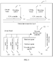
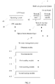
- FIG. 1 A system architecture of a multi-core processor system based on many-core decoupling and applied in the embodiments of the present invention is shown in FIG. 1 .
- a many-core decoupling architecture refers to separating existing hardware in a computer to form hardware networks managed by all parts obtained after decoupling, that is, decoupling the hardware in the computer into parts such as a computing resource pool, an input/output (IO for short) device pool, a memory pool, a connection network, and a resource management center.
- IO input/output
- Each CPU board 11 includes multiple CPU cores
- the CPU boards 11 include multiple CPU cores.
- An operating system runs in a first CPU core among the foregoing multiple CPU cores. These CPU cores may be integrated on one CPU board 11 or integrated on multiple CPU boards 11.
- An IO device pool of the multi-core processor system 1 is a device board 12 in FIG. 1 , and multiple IO devices (for example, a disk, a network interface card, a video graphics array (VGA for short) video card) are integrated on the device board 12.
- M physical network interface cards 121 are integrated on the device board 12, the foregoing physical network interface cards 121 are multi-queue network interface cards, each multi-queue network interface card includes multiple hardware queues, and the foregoing hardware queues are used to receive and transmit data run in CPU cores bound to the hardware queues.
- each board in the multi-core processor system 1 is integrated with a controller (for example, a cloud controller) configured to control hardware resources on the board, for example, a CPU controller 111 configured to control all CPU cores on the CPU board 11, and a network interface card controller 122 configured to control physical network interface cards 121 on the device board.
- a resource management center 13 in the multi-core processor system 1 controls allocation and interconnection of hardware resources by using the controller on each board, so as to manage all hardware resources in the multi-core processor system 1.
- the resource management center 13 selects a part of the CPU cores from the CPU boards 11, selects a segment of memory from a memory pool, selects several IO devices from the IO device board 12, and then connects the selected parts by using the controller on each board, and isolates the connected parts from another part, so as to form a complete small computer.
- the resource management center 13 allocates a different hardware resource to each operating system. As a result, hardware protection isolation exists between the operating systems.
- the embodiments of the present invention provide a new network interface card configuration method.
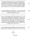
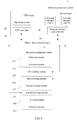
- an embodiment of the present invention provides a network interface card configuration method, and as shown in FIG. 2 , the method specifically includes the following steps.
- a resource management center obtains a network interface card allocation request of an operating system that runs in a first CPU core.
- the foregoing first CPU core is any core on any CPU board (for example, a CPU#1 board) in FIG. 1
- the foregoing network interface card allocation request includes a network parameter of a network service required by the operating system that runs in the first CPU core, and the network parameter of the network service is used to request a network interface card that can provide the required network service.
- the foregoing network parameter of the network service includes at least a network segment connected by the network service and bandwidth required by the network service.
- a network segment that needs to be connected by the operating system may be multiple network segments, that is, the operating system needs to be simultaneously connected to multiple network segments.
- the resource management center selects, from M physical network interface cards and based on a network parameter of a network service required by the operating system, a target physical network interface card that conforms to the network parameter.
- the resource management center may match, according to a network segment connected by a network service required by an operating system X, the network segment to a network segment of each physical network interface card in the M physical network interface cards, so as to obtain at least one target physical network interface card that matches the network segment.
- the resource management center separately selects at least one target hardware queue from each target physical network interface card.
- the resource management center may select, according to bandwidth or a data traffic volume required by the network service required by the operating system X, one or more target hardware queues from hardware queues of each obtained target physical network interface card, and obtain a queue identifier ID of each hardware queue of the at least one target hardware queue.
- the resource management center sends a command message to a network interface card controller.
- the foregoing command message includes the queue ID of each target hardware queue, and is used to instruct the network interface card controller to bind interrupt routing of each target hardware queue to the first CPU core on the CPU board.
- the resource management center After the resource management center obtains a queue ID of a target hardware queue used to form a virtual network interface card required by the operating system, the resource management center sends the command message to the network interface card controller, so as to instruct the network interface card controller to unbind each target hardware queue from a CPU core that is currently bound to the target hardware queue, and then bind each target hardware queue to the first CPU core.
- the resource management center marks, in a database, that the target hardware queues are allocated, and in addition, the resource management center modifies queue information of the target hardware queues stored in the database and modifies queue statuses of the target hardware queues into "allocated".
- the resource management center receives queue information of each target hardware queue fed back by the network interface card controller according to a queue ID of the target hardware queue.
- the foregoing queue information of each hardware queue includes a queue ID of the hardware queue, a CPU core address bound to the interrupt routing, a direct memory access (DMA for short) mapping address, and a current status of the hardware queue, and the foregoing current status of the hardware queue indicates whether the hardware queue is allocated.
- DMA direct memory access
- the resource management center sends an instruction message to a CPU controller on a CPU board.
- the foregoing instruction message includes the queue information of the target hardware queue and network interface card information that are used to construct a virtual network interface card, and the instruction message is used to instruct the CPU controller on the CPU board to generate, according to the network interface card information and the queue information of the target hardware queue, the virtual network interface card that can provide the network service for the operating system.
- the resource management center first sends, to the CPU controller on the CPU board, the network interface card information used to construct the virtual network interface card.
- the resource management center After the CPU controller constructs an architecture of the virtual network interface card according to the network interface card information of the virtual network interface card, the resource management center sends the received queue information of all the target hardware queues to the CPU controller, so that the CPU controller generates, according to all the target hardware queues, the virtual network interface card that provides the network service for the operating system.
- a function of cross-network interface card and cross-network segment data processing can be provided by the virtual network.
- the CPU controller After the CPU controller generates, according to the target hardware queues, a new virtual network interface card, the CPU controller establishes an IO channel to the network interface card controller that controls the M physical network interface cards, and the IO channel is used to forward a data packet received by these target hardware queues.
- a resource management center obtains a network interface card allocation request of an operating system that runs in a first CPU core, selects, from M physical network interface cards and based on a network parameter of a network service required by the operating system, a target physical network interface card that conforms to the network parameter, and separately selects at least one target hardware queue from each target physical network interface card. Then the resource management center sends a command message to a network interface card controller and receives queue information of the target hardware queue fed back by the network interface card controller.
- the resource management center sends an instruction message to a CPU controller on a CPU board, so that the CPU controller generates, according to the network interface card information and the target hardware queues, a new virtual network interface card that can provide the required network service for the operating system that runs on the CPU board.
- a multi-queue virtual network interface card that crosses physical network interface cards can be flexibly configured according to an operating system requirement. As a result, cross-network segment and cross-network interface card data processing are implemented, resources of multiple network segments and multiple network interface cards are fully used, and resource utilization is improved.
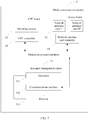
- Embodiment 2 of the present invention provides another network interface card configuration method, and as shown in FIG. 3A and FIG. 3B , the method specifically includes the following steps.
- a resource management center obtains a network interface card allocation request of an operating system that runs in a first CPU core.
- the resource management center before the resource management center executes the method provided in this embodiment, the resource management center further needs to obtain device information of all CPU cores and all device information (for example, network interface card parameters of all physical network interface cards on a device board, for example, a network segment connected by a network interface card, bandwidth, and a network interface card feature) on the device board, and needs to establish a database (for example, a device resource pool) before implementing the method of this embodiment for the first time or each time.
- device information of all CPU cores and all device information for example, network interface card parameters of all physical network interface cards on a device board, for example, a network segment connected by a network interface card, bandwidth, and a network interface card feature
- the method further includes the following steps: 301a.
- the resource management center receives a network interface card parameter of each physical network interface card in M physical network interface cards, and queue information of a hardware queue in each physical network interface card in the M physical network interface cards, where the network interface card parameter and the queue information are sent by a network interface card controller.
- the foregoing network interface card parameter of each physical network interface card includes a network segment to which the physical network interface card belongs, bandwidth required by the physical network interface card, a network interface card ID of the physical network interface card, a hardware queue number N, and a queue ID of a to-be-allocated hardware queue.
- the foregoing queue information of a hardware queue includes a queue ID of the hardware queue, a CPU core address bound to interrupt routing, a DMA mapping address, and a current status of the hardware queue, and the current status of the hardware queue indicates whether the hardware queue is allocated.
- the resource management center allocates a corresponding network interface card ID to each physical network interface card in the M physical network interface cards.
- the resource management center correspondingly stores, in a first database, the network interface card parameter of each physical network interface card and the network interface card ID of each physical network interface card in the M physical network interface cards, and correspondingly stores, in a second database, the queue information of a hardware queue in each physical network interface card and the network interface card ID of each physical network interface card.
- the foregoing first database may be referred to as a network interface card database and is used to store a network interface card parameter of a related physical network interface card.
- the foregoing second database may be referred to as a queue database and is used to store queue information of a hardware queue in related physical network interface card.
- the first database and the second database that are described in this embodiment may be a same database.
- the resource management center selects, from the M physical network interface cards and based on a network parameter of a network service required by the operating system, a target physical network interface card that conforms to the network parameter.
- step 302 specifically includes the following steps.
- the resource management center obtains, from the preconfigured first database and based on a network segment connected by the network service required by the operating system, a network interface card ID of a target physical network interface card that matches the network segment.
- the foregoing first database stores at least the network interface card parameter of each physical network interface card in the M physical network interface cards.
- the network interface card parameter includes a network segment to which the physical network interface card belongs and a network interface card ID of the physical network interface card.
- network segments connected by a network service required by an operating system X are a network segment 1, a network segment 2, and a network segment 3
- the resource management center matches each of the network segment 1, the network segment 2, and the network segment 3 to the network segments that are stored in the first database and to which the M physical network interface cards belong, so as to obtain a network interface card A, a network interface card B, and a network interface card C that respectively belong to the network segment 1, the network segment 2, and the network segment 3.
- the resource management center separately selects at least one target hardware queue from each target physical network interface card.
- step 303 specifically includes the following steps.
- the resource management center searches, according to the network interface card ID of the target physical network interface card, the preconfigured second database for queue information of each hardware queue in the target physical network interface card.
- the foregoing second database stores at least the queue information of each hardware queue of each physical network interface card in the M physical network interface cards.
- the resource management center selects, according to bandwidth required by the network service, the at least one target hardware queue from each target physical network interface card, and obtains a queue ID of each target hardware queue from the queue information of all the hardware queues in each physical network interface card.
- the resource management center selects, according to bandwidth required by the network service required by the operating system X or a data traffic volume of the network service required by the operating system X, a corresponding quantity of target hardware queues from each obtained target physical network interface card. For example, if target physical network interface cards are the network interface card A, the network interface card B, and the network interface card C, and the bandwidth required by the operating system X is small, the resource management center selects, from each of the network interface card A, the network interface card B, and the network interface card C, any hardware queue as the target hardware queue, and obtains the queue ID of each target hardware queue from the queue information of all hardware queues in each physical network interface card, so as to form a new virtual network interface card that can cross network segments and cross physical network interface cards.
- the resource management center sends a command message to a network interface card controller.
- the resource management center receives a queue information of the target hardware queue fed back by the network interface card controller according to the queue ID of each target hardware queue.
- the resource management center sends an instruction message to a CPU controller on a CPU board.
- step 301 to step 306 for detailed process of each step in step 301 to step 306 herein, reference may be made to step 201 to step 206 in Embodiment 1, and details are not described in this embodiment of the present invention.
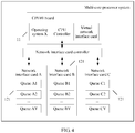
- Embodiment 2 is provided herein by applying Embodiment 2 to the multi-core processor system shown in FIG. 1 .
- the multi-core processor system includes: N central processing unit CPU boards 11, that is, a CPU#1 board, a CPU#2 board, ..., and a CPU #n board, three physical network interface cards 121, that is, a network interface card 1, a network interface card 2, and a network interface card 3, and a resource management center 13.
- N central processing unit CPU boards 11, that is, a CPU#1 board, a CPU#2 board, ..., and a CPU #n board
- three physical network interface cards 121 that is, a network interface card 1, a network interface card 2, and a network interface card 3, and a resource management center 13.
- an operating system X that runs on the CPU#1 board
- a quantity of the physical network interface cards 121 is three
- each physical network interface card 121 includes Y hardware queues
- the resource management center obtains information about operating systems and programs that run on all CPU boards, a to-be-run task, and all device information on a device board, such as network interface card parameters of all physical network interface cards on the device board, for example, a network segment connected by a network interface card, bandwidth, and a network interface card feature.
- a device resource pool is established before the method provided in this embodiment is executed for the first time.
- the resource management center obtains a network interface card allocation request of the operating system X that includes network parameters such as a network service priority, a connected network segment, and bandwidth.
- the resource management center After obtaining the network interface card allocation request, the resource management center matches, to network segments that are in the first database and to which all physical network interface cards stored belong, a network segment 1, a network segment 2, and a network segment 3 that need to be connected by the network service required by the operating system X, so as to obtain target physical network interface cards (for example, a network interface card A, a network interface card B, and a network interface card C) that separately match the network segment 1, the network segment 2, and the network segment 3 that need to be connected by the network service required by the operating system X, and obtain network interface card IDs corresponding to target physical network interface cards.
- target physical network interface cards for example, a network interface card A, a network interface card B, and a network interface card C
- the resource management center searches the second database for queue information (for example, information such as a queue ID, a CPU core address bound to interrupt routing, a DMA mapping address, and a current status of a hardware queue) of each hardware queue in the network interface card A, the network interface card B, and the network interface card C; selects, according to the data traffic volume required by the network service required by the operating system X, two hardware queues, A1 and A2, from the network interface card A and a B1 hardware queue and a C1 hardware queue respectively from the network interface card B and the network interface card C; and obtains a queue ID of each target hardware queue from the queue information of all hardware queues.
- queue information for example, information such as a queue ID, a CPU core address bound to interrupt routing, a DMA mapping address, and a current status of a hardware queue
- the resource management center sends the queue IDs of the four hardware queues, A1, A2, B1, and C1, to a network interface card controller, and the network interface card controller feeds back queue information corresponding to the four hardware queues, so that the resource management center sends the queue information corresponding to the four hardware queues to a CPU controller on the CPU#1 board.
- the resource management center after receiving the queue information of the four hardware queues, A1, A2, B1, and C1, the resource management center sends, to the CPU controller on the CPU#1 board, network interface card information used to construct the virtual network interface card.
- the CPU controller constructs an architecture of the virtual network interface card according to the network interface card information.
- the resource management center sends the queue information of the four hardware queues, A1, A2, B1, and C1, to the CPU controller.
- the CPU controller integrates the four hardware queues and the architecture of the virtual network interface card into the virtual network interface card that can provide the network service for the operating system X.
- the CPU controller on the CPU#1 board establishes an IO channel to the network interface card controller, so that the network interface card controller can send, by using the IO channel, a data packet received by the four hardware queues to the CPU core corresponding to the operating system X on the CPU#1 board.
- a resource management center obtains a network interface card allocation request of an operating system that runs in a first CPU core, selects, from M physical network interface cards and based on a network parameter of a network service required by the operating system, a target physical network interface card that conforms to the network parameter, and separately selects at least one target hardware queue from each target physical network interface card. Then the resource management center sends a command message to a network interface card controller and receives queue information of the target hardware queue fed back by the network interface card controller.
- the resource management center sends an instruction message to a CPU controller on a CPU board, so that the CPU controller generates, according to the network interface card information and the target hardware queues, a new virtual network interface card that can provide the required network service for the operating system that runs on the CPU board.
- a multi-queue virtual network interface card that crosses physical network interface cards can be flexibly configured according to an operating system requirement. As a result, cross-network segment and cross-network interface card data processing are implemented, resources of multiple network segments and multiple network interface cards are fully used, and resource utilization is improved.
- the multi-core processor system 4 includes: a resource management center 41, a device board 42, and a central processing unit CPU board 43.
- the device board 42 includes M physical network interface cards and a network interface card controller 44 configured to control the M physical network interface cards, and the M physical network interface cards are connected to the network interface card controller 44.
- the CPU board 43 includes multiple CPU cores and a CPU controller 45 configured to control the CPU cores on the CPU board 43.
- An operating system runs in a first CPU core among the foregoing multiple CPU cores, each physical network interface card includes multiple hardware queues, and the hardware queues are used to receive and transmit data that runs in CPU cores bound to the hardware queues.
- the resource management center 41 includes: an obtaining module 411, a selection module 412, a first sending module 413, a first receiving module 414, and a second sending module 415.
- the obtaining module 411 is configured to obtain a network interface card allocation request of the operating system that runs in the first CPU core, where the foregoing network interface card allocation request is used to request to allocate a network interface card that can provide a network service, and the network interface card allocation request includes a network parameter of the network service required by the operating system.
- the selection module 412 is configured to select, from the M physical network interface cards and based on the foregoing network parameter of the network service required by the operating system, a target physical network interface card that conforms to the network parameter.
- the foregoing selection module 412 is further configured to separately select at least one target hardware queue from each target physical network interface card.
- the first sending module 413 is configured to send a command message to the network interface card controller 44, where the foregoing command message is used to instruct the network interface card controller 44 to bind interrupt routing of each target hardware queue to the first CPU core in which the operating system runs, and the command message includes a queue identifier ID of each target hardware queue.
- the first receiving module 414 is configured to receive queue information of each target hardware queue fed back by the foregoing network interface card controller 44 according to the queue identifier ID of the target hardware queue.
- the second sending module 415 is configured to send an instruction message to the CPU controller 45 on the CPU board 43, where the foregoing instruction message includes the queue information of the target hardware queue and network interface card information that are used to construct a virtual network interface card, and the instruction message is used to instruct the CPU controller 45 on the CPU board 43 to generate, according to the network interface card information and the queue information of the target hardware queue, a virtual network interface card that can provide the network service for the operating system.
- the foregoing network parameter of the network service required by the operating system includes at least a network segment connected by the network service and bandwidth required by the network service.
- the foregoing selection module 412 is specifically configured to: select, from a preconfigured first database and based on the network segment connected by the network service required by the operating system, a network interface card ID of a target physical network interface card that matches the foregoing network segment, where the first database stores a network interface card parameter of each physical network interface card in the M physical network interface cards, and the network interface card parameter includes a network segment to which the physical network interface card belongs and a network interface card ID of the physical network interface card.
- the foregoing selection module 412 is specifically configured to:
- the resource management center further includes: a second receiving module 416, an allocation module 417, and a storage module 418.
- the second receiving module 416 is configured to receive the network interface card parameter of each physical network interface card in the M physical network interface cards, and the queue information of a hardware queue in each physical network interface card in the M physical network interface cards, where the network interface card parameter and the queue information are sent by the network interface card controller 44.
- the allocation module 417 is configured to allocate a corresponding network interface card ID to each physical network interface card in the M physical network interface cards.
- the storage module 418 is configured to correspondingly store, in the first database, the network interface card parameter of each physical network interface card and the network interface card ID of each physical network interface card in the M physical network interface cards, and correspondingly store, in the second database, the queue information of a hardware queue in each physical network interface card and the network interface card ID of each physical network interface card.
- the foregoing queue information of a hardware queue includes a queue ID of the hardware queue, a CPU core address bound to the interrupt routing, a direct memory access DMA mapping address, and a current status of the hardware queue, and the foregoing current status of the hardware queue indicates whether the hardware queue is allocated.
- the resource management center obtains a network interface card allocation request of an operating system that runs in a first CPU core, selects, from M physical network interface cards and based on a network parameter of a network service required by the operating system, a target physical network interface card that conforms to the network parameter, and separately selects at least one target hardware queue from each target physical network interface card. Then the resource management center sends a command message to a network interface card controller and receives queue information of the target hardware queue fed back by the network interface card controller.
- the resource management center sends an instruction message to a CPU controller on a CPU board, so that the CPU controller generates, according to the network interface card information and the target hardware queues, a new virtual network interface card that can provide the required network service for the operating system that runs on the CPU board.
- a multi-queue virtual network interface card that crosses physical network interface cards can be flexibly configured according to an operating system requirement. As a result, cross-network segment and cross-network interface card data processing are implemented, resources of multiple network segments and multiple network interface cards are fully used, and resource utilization is improved.
- the multi-core processor system 5 includes: a resource management center 51, a device board 52, and a central processing unit CPU board 53.
- the device board 52 includes M physical network interface cards and a network interface card controller 54 configured to control the M physical network interface cards, and the M physical network interface cards are connected to the network interface card controller.
- the CPU board 53 includes multiple CPU cores and a CPU controller 55 configured to control the CPU cores on the CPU board 53.
- An operating system runs in a first CPU core among the foregoing multiple CPU cores, each physical network interface card includes multiple hardware queues, and the hardware queues are used to receive and transmit data that runs in CPU cores bound to the hardware queues.
- the resource management center 51 includes a processor 511 and a communications interface 512.
- the processor 511 is configured to obtain a network interface card allocation request of the operating system that runs in the first CPU core, where the network interface card allocation request is used to request to allocate a network interface card that can provide a network service, and the network interface card allocation request includes a network parameter of the network service required by the operating system.
- the processor 511 is further configured to select, from M physical network interface cards and based on the network parameter of the network service required by the operating system, a target physical network interface card that conforms to the network parameter.
- the processor 511 is further configured to separately select at least one target hardware queue from each target physical network interface card.
- the processor 511 is configured to send a command message to the network interface card controller 54 by using the communications interface 512, where the command message is used to instruct the network interface card controller to bind interrupt routing of each target hardware queue to the first CPU core in which the operating system runs, and the command message includes a queue identifier ID of each target hardware queue.
- the processor 511 is further configured to receive, by using the communications interface 512, queue information of each target hardware queue fed back by the network interface card controller 54 according to the queue identifier ID of the target hardware queue.
- the processor 511 is further configured to send an instruction message to the CPU controller 55 on the CPU board 53 by using the communications interface 512, where the foregoing instruction message includes the queue information of the target hardware queue and network interface card information that are used to construct a virtual network interface card, and the instruction message is used to instruct the CPU controller 55 on the CPU board 53 to generate, according to the network interface card information and the queue information of the target hardware queue, a virtual network interface card that can provide the network service for the operating system.
- the foregoing network parameter of the network service required by the operating system includes at least a network segment connected by the network service and bandwidth required by the network service.
- the processor 511 is specifically configured to: select, from a preconfigured first database and based on the network segment connected by the network service required by the operating system, a network interface card ID of a target physical network interface card that matches the network segment, where the first database stores a network interface card parameter of each physical network interface card in the M physical network interface cards, and the network interface card parameter includes a network segment to which the physical network interface card belongs and a network interface card ID of the physical network interface card.
- the processor 511 is specifically configured to:
- the resource management center further includes a memory 513.
- the processor 511 is further configured to receive, by using the communications interface 512, the network interface card parameter of each physical network interface card in the M physical network interface cards, and the queue information of a hardware queue in each physical network interface card in the M physical network interface cards, where the network interface card parameter and the queue information are sent by the network interface card controller 54.
- the processor 511 is further configured to allocate a corresponding network interface card ID to each physical network interface card in the M physical network interface cards.
- the memory 513 is configured to correspondingly store, in the first database, the network interface card parameter of each physical network interface card and the network interface card ID of each physical network interface card in the M physical network interface cards, and correspondingly store, in the second database, the queue information of a hardware queue in each physical network interface card and the network interface card ID of each physical network interface card.
- the foregoing queue information of a hardware queue includes a queue ID of the hardware queue, a CPU core address bound to the interrupt routing, a direct memory access DMA mapping address, and a current status of the hardware queue, and the foregoing current status of the hardware queue indicates whether the hardware queue is allocated.
- the resource management center obtains a network interface card allocation request of an operating system that runs in a first CPU core, selects, from M physical network interface cards and based on a network parameter of a network service required by the operating system, a target physical network interface card that conforms to the network parameter, and separately selects at least one target hardware queue from each target physical network interface card. Then the resource management center sends a command message to a network interface card controller and receives queue information of the target hardware queue fed back by the network interface card controller.
- the resource management center sends an instruction message to a CPU controller on a CPU board, so that the CPU controller generates, according to the network interface card information and the target hardware queues, a new virtual network interface card that can provide the required network service for the operating system that runs on the CPU board.
- a multi-queue virtual network interface card that crosses physical network interface cards can be flexibly configured according to an operating system requirement. As a result, cross-network segment and cross-network interface card data processing are implemented, resources of multiple network segments and multiple network interface cards are fully used, and resource utilization is improved.
- the multi-core processor system 1 includes a resource management center 13, a device board 12, and a central processing unit CPU board 11.
- the device board 12 includes M physical network interface cards 121 and a network interface card controller 122 configured to control the M physical network interface cards, and the M physical network interface cards 121 are connected to the network interface card controller 122.
- the CPU board 11 includes multiple CPU cores and a CPU controller 111 configured to control the CPU cores on the CPU board 11.
- An operating system runs in a first CPU core among the foregoing multiple CPU cores, each physical network interface card 121 includes multiple hardware queues, and the hardware queues are used to receive and transmit data that runs in CPU cores bound to the hardware queues.
- the multi-core processor system 1 includes a resource management center 13.
- the resource management center 13 is configured to obtain a network interface card allocation request of the operating system that runs in the first CPU core, where the network interface card allocation request is used to request to allocate a network interface card that can provide a network service, and the network interface card allocation request includes a network parameter of the network service required by the operating system.
- the resource management center 13 is further configured to select, from M physical network interface cards and based on the network parameter of the network service required by the operating system, a target physical network interface card that conforms to the network parameter.
- the resource management center 13 is further configured to separately select at least one target hardware queue from each target physical network interface card.
- the resource management center 13 is further configured to send a command message to the network interface card controller 122, where the command message includes a queue identifier ID of each target hardware queue.
- the network interface card controller 122 is configured to bind, according to the command message, interrupt routing of each target hardware queue to the first CPU core in which the operating system runs.
- the network interface card controller 122 is further configured to search queue information of each target hardware queue according to the queue identifier ID of the target hardware queue.
- the resource management center 13 is further configured to receive the queue information of the target hardware queue fed back by the network interface card controller 122.
- the resource management center 13 is further configured to send an instruction message to the CPU controller 111 on the CPU board 11, where the instruction message includes the queue information of the target hardware queue and network interface card information that are used to construct a virtual network interface card.
- the CPU controller 111 on the CPU board 11 is configured to generate, according to the queue information of the target hardware queue and the network interface card information that are in the foregoing instruction message, a virtual network interface card that can provide the network service for the operating system.
- the foregoing network parameter of the network service required by the operating system includes at least a network segment connected by the network service and bandwidth required by the network service.
- the resource management center 13 is specifically configured to: select, from a preconfigured first database and based on the network segment connected by the network service required by the operating system, a network interface card ID of a target physical network interface card 121 that matches the network segment, where the first database stores a network interface card parameter of each physical network interface card 121 in the M physical network interface cards 121, and the network interface card parameter includes a network segment to which the physical network interface card 121 belongs and a network interface card ID of the physical network interface card 121.
- the resource management center 13 is specifically configured to:
- the resource management center 13 is further configured to:
- the foregoing queue information of a hardware queue includes a queue ID of the hardware queue, a CPU core address bound to the interrupt routing, a direct memory access DMA mapping address, and a current status of the hardware queue, and the foregoing current status of the hardware queue indicates whether the hardware queue is allocated.
- a resource management center obtains a network interface card allocation request of an operating system that runs in a first CPU core, selects, from M physical network interface cards and based on a network parameter of a network service required by the operating system, a target physical network interface card that conforms to the network parameter, and separately selects at least one target hardware queue from each target physical network interface card. Then the resource management center sends a command message to a network interface card controller and receives queue information of the target hardware queue fed back by the network interface card controller.
- the resource management center sends an instruction message to a CPU controller on a CPU board, so that the CPU controller generates, according to the network interface card information and the target hardware queues, a new virtual network interface card that can provide the required network service for the operating system that runs on the CPU board.
- a multi-queue virtual network interface card that crosses physical network interface cards can be flexibly configured according to an operating system requirement. As a result, cross-network segment and cross-network interface card data processing are implemented, resources of multiple network segments and multiple network interface cards are fully used, and resource utilization is improved.
- the disclosed system and method may be implemented in other manners.
- the described system embodiment is merely an example.
- the module division is merely logical function division and may be other division in actual implementation.
- a plurality of modules or components may be combined or integrated into another system, or some features may be ignored or not performed.
- the displayed or discussed mutual couplings or direct couplings or communication connections may be implemented through some interfaces.
- the indirect couplings or communication connections between the modules may be implemented in electronic, mechanical, or other forms.
Claims (15)
- Konfigurationsverfahren für eine Netzwerkkarte, angewandt auf ein Multi-Kern-Prozessorsystem (1), wobei das Multi-Kern-Prozessorsystem (1) ein Ressourcenverwaltungszentrum (13), eine Einrichtungsplatine (12) und eine Platine (11) einer zentralen Verarbeitungseinheit CPU umfasst; die Einrichtungsplatine (12) M physische Netzwerkkarten (121) und eine Netzwerkkartensteuerung (122) umfasst, ausgelegt zum Steuern der M physischen Netzwerkkarten (121), und die M physischen Netzwerkkarten (121) mit der Netzwerkkartensteuerung (122) verbunden sind; die CPU-Platine (11) mehrere CPU-Kerne und eine CPU-Steuerung (111) umfasst, ausgelegt zum Steuern der CPU-Kerne auf der CPU-Platine (11), wobei ein Betriebssystem in einem ersten CPU-Kern unter den mehreren CPU-Kernen ausgeführt wird, jede physische Netzwerkkarte (121) mehrere Hardware-Warteschlangen umfasst und die Hardware-Warteschlangen verwendet werden zum Empfangen und Senden von Daten, die in für die Hardware-Warteschlangen vorgesehenen CPU-Kernen ausgeführt werden, und das Verfahren umfasst:Erhalten (201) einer Zuweisungsanforderung des Betriebssystems, das im ersten CPU-Kern ausgeführt wird, einer virtuellen Netzwerkkarte durch das Ressourcenverwaltungszentrum (13), wobei die Zuweisungsanforderung der virtuellen Netzwerkkarte verwendet wird, um die Zuweisung einer virtuellen Netzwerkkarte anzufordern, die einen Netzwerkdienst bereitstellen kann, und die Zuweisungsanforderung der virtuellen Netzwerkkarte einen Netzwerkparameter des durch das Betriebssystem angeforderten Netzwerkdienstes umfasst;Auswählen (202), aus den M physischen Netzwerkkarten (121) durch das Ressourcenverwaltungszentrum (13) und basierend auf dem Netzwerkparameter des durch das Betriebssystem angeforderten Netzwerkdienstes, von mindestens einer physischen Ziel-Netzwerkkarte, die den Netzwerkparameter einhält;separates Auswählen (203) durch das Ressourcenverwaltungszentrum (13) von mindestens einer Ziel-Hardware-Warteschlange aus jeder physischen Ziel-Netzwerkkarte;Senden (204) einer Befehlsmeldung zur Netzwerkkartensteuerung (122) durch das Ressourcenverwaltungszentrum (13), wobei die Befehlsmeldung verwendet wird, um die Netzwerkkartensteuerung (122) anzuweisen zum Binden von Interrupt-Wegführung von jeder Ziel-Hardware-Warteschlange an den ersten CPU-Kern, in dem das Betriebssystem ausgeführt wird, und die Befehlsmeldung eine Warteschlangen-ID-Kennung von jeder Ziel-Hardware-Warteschlange umfasst, um die Netzwerkkartensteuerung (122) anzuweisen, die Warteschlangeninformation jeder Ziel-Hardware-Warteschlange entsprechend der Warteschlangen-ID-Kennung von jeder Ziel-Hardware-Warteschlange zu durchsuchen;Empfangen (205), durch das Ressourcenverwaltungszentrum (13), von Warteschlangeninformation jeder Ziel-Hardware-Warteschlange, zurückgemeldet durch die Netzwerkkartensteuerung (122) gemäß der Warteschlangen-ID-Kennung von jeder Ziel-Hardware-Warteschlange, undSenden (206) einer Anweisungsmeldung zur CPU-Steuerung (111) auf der CPU-Platine (11) durch das Ressourcenverwaltungszentrum (13), wobei die Anweisungsmeldung die Warteschlangeninformation von jeder Ziel-Hardware-Warteschlange und Netzwerkkarteninformation von einer virtuellen Netzwerkkarte umfasst, die verwendet werden, um die virtuelle Netzwerkkarte zu konstruieren, und die Anweisungsmeldung verwendet wird, um die CPU-Steuerung (111) auf der CPU-Platine (11) anzuweisen, gemäß der Netzwerkkarteninformation eine Architektur der virtuellen Netzwerkkarte zu konstruieren und gemäß der Warteschlangeninformation aller Ziel-Hardware-Warteschlangen die virtuelle Netzwerkkarte zu erzeugen, die den Netzwerkdienst für das Betriebssystem bereitstellen kann,wobei der Netzwerkparameter des durch das Betriebssystem angeforderten Netzwerkdienstes mindestens ein Netzwerksegment, das durch den Netzwerkdienst verbunden ist, und für den Netzwerkdienst erforderliche Bandbreite umfasst.
- Verfahren nach Anspruch 1, wobei
das Auswählen (202, 302) einer physischen Ziel-Netzwerkkarte, die den Netzwerkparameter einhält, aus den M physischen Netzwerkkarten (121) und basierend auf dem Netzwerkparameter des durch das Betriebssystem angeforderten Netzwerkdienstes im Einzelnen umfasst:Auswählen (302a) einer Netzwerkkarten-ID einer physischen Ziel-Netzwerkkarte, die dem Netzwerksegment entspricht, aus einer voreingestellten ersten Datenbank und basierend auf dem mit dem durch das Betriebssystem angeforderten Netzwerkdienst verbundenen Netzwerksegment, wobei die erste Datenbank einen Netzwerkkarten-Parameter jeder physischen Netzwerkkarte in den M physischen Netzwerkkarten (121) speichert und der Netzwerkkarten-Parameter ein Netzwerksegment, zu dem die physische Netzwerkkarte gehört, und eine Netzwerkkarten-ID der physischen Netzwerkkarte umfasst. - Verfahren nach Anspruch 1 oder 2, wobei
das separate Auswählen (203, 303) von mindestens einer Ziel-Hardware-Warteschlange von jeder physischen Ziel-Netzwerkkarte umfasst:Durchsuchen (303a) einer voreingestellten zweiten Datenbank entsprechend der Netzwerkkarten-ID der physischen Ziel-Netzwerkkarte nach Warteschlangeninformation von jeder Hardware-Warteschlange in der physischen Ziel-Netzwerkkarte, wobei die zweite Datenbank Warteschlangeninformation von jeder Hardware-Warteschlange in jeder physischen Netzwerkkarte in den M physischen Netzwerkkarten speichert; undAuswählen (303b) der mindestens einen Ziel-Hardware-Warteschlange von jeder physischen Ziel-Netzwerkkarte gemäß der durch den Netzwerkdienst erforderlichen Bandbreite und Erhalten einer Warteschlangen-ID von jeder Ziel-Hardware-Warteschlange aus der Warteschlangeninformation aller Hardware-Warteschlangen in jeder physischen Netzwerkkarte. - Verfahren nach einem der Ansprüche 1 bis 3, wobei vor dem Erhalten (201, 301) einer Zuweisungsanforderung des Betriebssystems, das auf der CPU-Platine (11) ausgeführt wird, einer Netzwerkkarte durch das Ressourcenverwaltungszentrum (13) das Verfahren ferner umfasst:Empfangen (301a) eines Netzwerkkarten-Parameters von jeder physischen Netzwerkkarte in den M physischen Netzwerkkarten (121), wobei der Netzwerkkarten-Parameter ein Netzwerksegment umfasst, zu dem die physische Netzwerkkarte gehört, und eine Netzwerkkarten-ID der physischen Netzwerkkarte; und der Warteschlangeninformation einer Hardware-Warteschlange in jeder physischen Netzwerkkarte in den M physischen Netzwerkkarten (121), wobei der Netzwerkkarten-Parameter und die Warteschlangeninformation durch die Netzwerkkartensteuerung (122) versendet werden;Zuweisen (301b) einer dazugehörigen Netzwerkkarten-ID zu jeder physischen Netzwerkkarte in den M physischen Netzwerkkarten (121); unddementsprechendes Speichern (301c) des Netzwerkkarten-Parameters jeder physischen Netzwerkkarte und der Netzwerkkarten-ID von jeder physischen Netzwerkkarte in den M physischen Netzwerkkarten in der ersten Datenbank und dementsprechendes Speichern der Warteschlangeninformation einer Hardware-Warteschlange in jeder physischen Netzwerkkarte und der Netzwerkkarten-ID von jeder physischen Netzwerkkarte in der zweiten Datenbank.
- Verfahren nach einem der Ansprüche 1 bis 4, wobei
die Warteschlangeninformation einer Hardware-Warteschlange eine Warteschlangen-ID-Kennung der Hardware-Warteschlange, eine an die Interrupt-Wegführung gebundene CPU-Kern-Adresse, eine Speicherdirektzugriffs(DMA)-Abbildungsadresse und einen aktuellen Status der Hardware-Warteschlange umfasst und der aktuelle Status der Hardware-Warteschlange verwendet wird, um anzugeben, ob die Hardware-Warteschlange zugeordnet ist. - Ressourcenverwaltungszentrum (13, 41), wobei das Ressourcenverwaltungszentrum (13,41) auf ein Multi-Kern-Prozessorsystem (1) angewandt wird und das Multi-Kern-Prozessorsystem (1) das Ressourcenverwaltungszentrum (13, 41), eine Einrichtungsplatine (12) und eine Platine (11) einer zentralen Verarbeitungseinheit CPU umfasst; die Einrichtungsplatine (12) M physische Netzwerkkarten (121) und eine Netzwerkkartensteuerung (122) umfasst, ausgelegt zum Steuern der M physischen Netzwerkkarten (121), und die M physischen Netzwerkkarten (121) mit der Netzwerkkartensteuerung (122) verbunden sind; die CPU-Platine (11) mehrere CPU-Kerne und eine CPU-Steuerung (111) umfasst, ausgelegt zum Steuern der CPU-Kerne auf der CPU-Platine (11), wobei ein Betriebssystem in einem ersten CPU-Kern unter den mehreren CPU-Kernen ausgeführt wird, jede physische Netzwerkkarte mehrere Hardware-Warteschlangen umfasst und die Hardware-Warteschlangen verwendet werden zum Empfangen und Senden von Daten, die in für die Hardware-Warteschlangen vorgesehenen CPU-Kernen ausgeführt werden, und
das Ressourcenverwaltungszentrum (13, 41) umfasst:ein Erhaltmodul (411), ausgelegt zum Erhalten einer Zuweisungsanforderung des Betriebssystems, das im ersten CPU-Kern ausgeführt wird, einer virtuellen Netzwerkkarte, wobei die Zuweisungsanforderung der virtuellen Netzwerkkarte verwendet wird, um die Zuweisung einer virtuellen Netzwerkkarte anzufordern, die einen Netzwerkdienst bereitstellen kann, und die Zuweisungsanforderung für die Netzwerkkarte einen Netzwerkparameter des durch das Betriebssystem angeforderten Netzwerkdienstes umfasst;ein Auswahlmodul (412), ausgelegt zum Auswählen aus den M physischen Netzwerkkarten (121), und basierend auf dem Netzwerkparameter des durch das Betriebssystem angeforderten Netzwerkdienstes von mindestens einer physischen Ziel-Netzwerkkarte, die den Netzwerkparameter einhält, wobei das Auswahlmodul (412) ferner ausgelegt ist, um separat mindestens eine Ziel-Hardware-Warteschlange von jeder physischen Ziel-Netzwerkkarte auszuwählen;ein erstes Sendemodul (413), ausgelegt zum Senden einer Befehlsmeldung an die Netzwerkkartensteuerung (122), wobei die Befehlsmeldung verwendet wird, um die Netzwerkkartensteuerung anzuweisen, die Interrupt-Wegführung von jeder Ziel-Hardware-Warteschlange an den ersten CPU-Kern zu binden, in dem das Betriebssystem ausgeführt wird, und die Befehlsmeldung eine Warteschlangen-ID-Kennung von jeder Ziel-Hardware-Warteschlange umfasst;ein erstes Empfangsmodul (414), ausgelegt zum Empfangen von Warteschlangeninformation jeder Ziel-Hardware-Warteschlange, zurückgemeldet durch die Netzwerkkartensteuerung (122) gemäß der Warteschlangen-ID-Kennung von jeder Ziel-Hardware-Warteschlange; undein zweites Sendemodul (415), ausgelegt zum Senden einer Anweisungsmeldung zur CPU-Steuerung auf der CPU-Platine, wobei die Anweisungsmeldung die Warteschlangeninformation jeder Ziel-Hardware-Warteschlange und Netzwerkkarteninformation einer virtuellen Netzwerkkarte umfasst, die verwendet werden, um die virtuelle Netzwerkkarte zu konstruieren, und die Anweisungsmeldung verwendet wird, um die CPU-Steuerung (111) auf der CPU-Platine (11) anzuweisen, gemäß der Netzwerkkarteninformation eine Architektur der virtuellen Netzwerkkarte zu konstruieren und gemäß der Warteschlangeninformation aller Ziel-Hardware-Warteschlangen die virtuelle Netzwerkkarte zu erzeugen, die den Netzwerkdienst für das Betriebssystem bereitstellen kann,wobei der Netzwerkparameter des durch das Betriebssystem angeforderten Netzwerkdienstes mindestens ein Netzwerksegment, das durch den Netzwerkdienst verbunden ist, und für den Netzwerkdienst erforderliche Bandbreite umfasst. - Ressourcenverwaltungszentrum (13, 41) nach Anspruch 6, wobei das Auswahlmodul (412) im Einzelnen ausgelegt ist zum Auswählen einer Netzwerkkarten-ID einer physischen Ziel-Netzwerkkarte, die dem Netzwerksegment entspricht, aus einer voreingerichteten ersten Datenbank und basierend auf dem durch das Betriebssystem angeforderten Netzwerkdienst verbundenen Netzwerksegment, wobei die erste Datenbank einen Netzwerkkarten-Parameter von jeder physischen Netzwerkkarte in den M physischen Netzwerkkarten (121) speichert und der Netzwerkkarten-Parameter ein Netzwerksegment umfasst, zu dem die physische Netzwerkkarte gehört, und eine Netzwerkkarten-ID der physischen Netzwerkkarte.
- Ressourcenverwaltungszentrum (13, 41) nach Anspruch 6 oder 7, wobei das Auswahlmodul (412) im Einzelnen ausgelegt ist zum Durchsuchen einer voreingerichteten zweiten Datenbank nach Warteschlangeninformation jeder Hardware-Warteschlange in der physischen Ziel-Netzwerkkarte entsprechend der Netzwerkkarten-ID der physischen Ziel-Netzwerkkarte, wobei die zweite Datenbank Warteschlangeninformation von jeder Hardware-Warteschlange in jeder physischen Netzwerkkarte in den M physischen Netzwerkkarten (121) speichert; und
Auswählen der mindestens einen Ziel-Hardware-Warteschlange aus jeder physischen Ziel-Netzwerkkarte entsprechend der durch den Netzwerkdienst angeforderten Bandbreite und Erhalten einer Warteschlangen-ID von jeder Ziel-Hardware-Warteschlange aus der Warteschlangeninformation von allen Hardware-Warteschlangen in jeder physischen Netzwerkkarte. - Ressourcenverwaltungszentrum (13, 41) nach einem der Ansprüche 6 bis 8, wobei das Ressourcenverwaltungszentrum (13, 41) ferner umfasst:ein zweites Empfangsmodul (416), ausgelegt zum Empfangen eines Netzwerkkarten-Parameters von jeder physischen Netzwerkkarte in den M physischen Netzwerkkarten (121), wobei der Netzwerkkarten-Parameter ein Netzwerksegment umfasst, zu dem die physische Netzwerkkarte gehört, und eine Netzwerkkarten-ID der physischen Netzwerkkarte, und der Warteschlangeninformation einer Hardware-Warteschlange in jeder physischen Netzwerkkarte in den M physischen Netzwerkkarten (121), wobei der Netzwerkkarten-Parameter und die Warteschlangeninformation durch die Netzwerkkartensteuerung (122) gesendet werden;ein Zuweisungsmodul (417), ausgelegt zum Zuweisen einer entsprechenden Netzwerkkarten-ID zu jeder physischen Netzwerkkarte in den M physischen Netzwerkkarten (121); undein Speichermodul (418), ausgelegt zum entsprechenden Speichern des Netzwerkkarten-Parameters jeder physischen Netzwerkkarte und der Netzwerkkarten-ID von jeder physischen Netzwerkkarte in den M physischen Netzwerkkarten (121) in der ersten Datenbank und zum entsprechenden Speichern der Warteschlangeninformation einer Hardware-Warteschlange in jeder physischen Netzwerkkarte und der Netzwerkkarten-ID jeder physischen Netzwerkkarte in der zweiten Datenbank.
- Ressourcenverwaltungszentrum (13, 41) nach einem der Ansprüche 6 bis 9, wobei die Warteschlangeninformation einer Hardware-Warteschlange eine Hardware-Warteschlangen-ID-Kennung, eine an die Interrupt-Wegführung gebundene CPU-Kern-Adresse, eine Speicherdirektzugriffs(DMA)-Abbildungsadresse und einen aktuellen Status der Hardware-Warteschlange umfasst und der aktuelle Status der Hardware-Warteschlange verwendet wird, um anzugeben, ob die Hardware-Warteschlange zugeordnet ist.
- Multi-Kern-Prozessorsystem (5), wobei das Multi-Kern-Prozessorsystem (5) ein Ressourcenverwaltungszentrum (51), eine Einrichtungsplatine (52) und eine Platine (53) einer zentralen Verarbeitungseinheit CPU umfasst; die Einrichtungsplatine (52) M physische Netzwerkkarten und eine Netzwerkkartensteuerung (54) umfasst, ausgelegt zum Steuern der M physischen Netzwerkkarten, und die M physischen Netzwerkkarten mit der Netzwerkkartensteuerung (54) verbunden sind; die CPU-Platine (53) mehrere CPU-Kerne und eine CPU-Steuerung umfasst, ausgelegt zum Steuern der CPU-Kerne auf der CPU-Platine (53), wobei ein Betriebssystem in einem ersten CPU-Kern unter den mehreren CPU-Kernen ausgeführt wird, jede physische Netzwerkkarte mehrere Hardware-Warteschlangen umfasst und die Hardware-Warteschlangen verwendet werden zum Empfangen und Senden von Daten, die in für die Hardware-Warteschlangen vorgesehenen CPU-Kernen ausgeführt werden;
das Ressourcenverwaltungszentrum (51) ausgelegt ist zum Erhalten einer Zuweisungsanforderung des Betriebssystems, das im ersten CPU-Kern ausgeführt wird, einer virtuellen Netzwerkkarte, wobei die Zuweisungsanforderung der virtuellen Netzwerkkarte verwendet wird, um die Zuweisung einer virtuellen Netzwerkkarte anzufordern, die einen Netzwerkdienst bereitstellen kann, und die Zuweisungsanforderung für die virtuelle Netzwerkkarte einen Netzwerkparameter des durch das Betriebssystem angeforderten Netzwerkdienstes umfasst;
das Ressourcenverwaltungszentrum (51) ferner ausgelegt ist zum Auswählen von mindestens einer physischen Ziel-Netzwerkkarte, die den Netzwerkparameter einhält, aus den M physischen Netzwerkkarten und basierend auf dem Netzwerkparameter des durch das Betriebssystem angeforderten Netzwerkdienstes, und zum separaten Auswählen von mindestens einer Ziel-Hardware-Warteschlange aus jeder physischen Ziel-Netzwerkkarte;
das Ressourcenverwaltungszentrum ferner ausgelegt ist zum Senden einer Befehlsmeldung zur Netzwerkkartensteuerung (54), wobei die Befehlsmeldung eine Warteschlangen-ID-Kennung von jeder Ziel-Hardware-Warteschlange umfasst;
die Netzwerkkartensteuerung (54) ausgelegt ist zum Binden der Interrupt-Wegführung jeder Ziel-Hardware-Warteschlange entsprechend der Befehlsmeldung an den ersten CPU-Kern, in dem das Betriebssystem ausgeführt wird;
die Netzwerkkartensteuerung (54) ferner ausgelegt ist zum Durchsuchen von Warteschlangeninformation jeder Ziel-Hardware-Warteschlange entsprechend der Warteschlangen-ID-Kennung jeder Ziel-Hardware-Warteschlange;
das Ressourcenverwaltungszentrum (51) ferner ausgelegt ist zum Empfangen der von jeder durch die Netzwerkkartensteuerung (54) zurückgemeldeten Warteschlangeninformation jeder Ziel-Hardware-Warteschlange;
das Ressourcenverwaltungszentrum (51) ferner ausgelegt ist zum Senden einer Anweisungsmeldung an die CPU-Steuerung auf der CPU-Platine, wobei die Anweisungsmeldung die Warteschlangeninformation jeder Ziel-Hardware-Warteschlange und die Netzwerkkarteninformation einer virtuellen Netzwerkkarte umfasst, die zum Konstruieren der virtuellen Netzwerkkarte verwendet werden; und die CPU-Steuerung (55) auf der CPU-Platine (53) ausgelegt ist zum Konstruieren entsprechend der Netzwerkkarteninformation, die in der Anweisungsmeldung ist, und zum Erzeugen der virtuellen Netzwerkkarte, die den Netzwerkdienst für das Betriebssystem bereitstellen kann, entsprechend der Warteschlangeninformation aller Ziel-Hardware-Warteschlangen, die in der Anweisungsmeldung sind,
wobei der Netzwerkparameter des durch das Betriebssystem angeforderten Netzwerkdienstes mindestens ein durch den Netzwerkdienst verbundenes Netzwerksegment und durch den Netzwerkdienst angeforderte Bandbreite umfasst. - Multi-Kern-Prozessorsystem (5) nach Anspruch 11, wobei das Ressourcenverwaltungszentrum (51) im Einzelnen ausgelegt ist zum Auswählen einer Netzwerkkarten-ID einer physischen Ziel-Netzwerkkarte, die dem Netzwerksegment entspricht, aus einer voreingerichteten ersten Datenbank und basierend auf dem durch das Betriebssystem angeforderten Netzwerkdienst verbundenen Netzwerksegment, wobei die erste Datenbank einen Netzwerkkarten-Parameter von jeder physischen Netzwerkkarte in den M physischen Netzwerkkarten speichert und der Netzwerkkarten-Parameter ein Netzwerksegment umfasst, zu dem die physische Netzwerkkarte gehört, und eine Netzwerkkarten-ID der physischen Netzwerkkarte.
- Multi-Kern-Prozessorsystem (5) nach Anspruch 11 oder 12, wobei das Ressourcenverwaltungszentrum (51) im Einzelnen ausgelegt ist zum Durchsuchen einer voreingerichteten zweiten Datenbank nach Warteschlangeninformation von jeder Hardware-Warteschlange in der physischen Ziel-Netzwerkkarte entsprechend der Netzwerkkarten-ID der physischen Ziel-Netzwerkkarte, wobei die zweite Datenbank Warteschlangeninformation jeder Hardware-Warteschlange in jeder physischen Netzwerkkarte in den M physischen Netzwerkkarten speichert; und
Auswählen der mindestens einen Ziel-Hardware-Warteschlange aus jeder physischen Ziel-Netzwerkkarte entsprechend der durch den Netzwerkdienst angeforderten Bandbreite und Erhalten einer Warteschlangen-ID von jeder Ziel-Hardware-Warteschlange aus der Warteschlangeninformation von allen Hardware-Warteschlangen in jeder physischen Netzwerkkarte. - Multi-Kern-Prozessorsystem (5) nach einem der Ansprüche 11 bis 13, wobei das Ressourcenverwaltungszentrum (51) ferner ausgelegt ist zum Empfangen eines Netzwerkkarten-Parameters von jeder physischen Netzwerkkarte in den M physischen Netzwerkkarten, wobei der Netzwerkkarten-Parameter ein Netzwerksegment, zu dem die physische Netzwerkkarte gehört, und eine Netzwerkkarten-ID der physischen Netzwerkkarte und die Warteschlangeninformation einer Hardware-Warteschlange in jeder physischen Netzwerkkarte in den M physischen Netzwerkkarten umfasst, wobei der Netzwerkkarten-Parameter und die Warteschlangeninformation durch die Netzwerkkartensteuerung (54) gesendet werden;
Zuweisen einer entsprechenden Netzwerkkarten-ID zu jeder physischen Netzwerkkarte in den M physischen Netzwerkkarten; und dementsprechendes Speichern des Netzwerkkarten-Parameters jeder physischen Netzwerkkarte und der Netzwerkkarten-ID jeder physischen Netzwerkkarte in den M physischen Netzwerkkarten in der ersten Datenbank und dementsprechendes Speichern der Warteschlangeninformation einer Hardware-Warteschlange in jeder physischen Netzwerkkarte und der Netzwerkkarten-ID jeder physischen Netzwerkkarte in der zweiten Datenbank. - Multi-Kern-Prozessorsystem (5) nach einem der Ansprüche 11 bis 14, wobei die Warteschlangeninformation einer Hardware-Warteschlange eine Warteschlangen-ID-Kennung der Hardware-Warteschlange, eine an die Interrupt-Wegführung gebundene CPU-Kern-Adresse, eine Speicherdirektzugriffs-DMA-Abbildungsadresse und einen aktuellen Status der Hardware-Warteschlange umfasst und der aktuelle Status der Hardware-Warteschlange verwendet wird, um anzugeben, ob die Hardware-Warteschlange zugeordnet ist.
Applications Claiming Priority (1)
| Application Number | Priority Date | Filing Date | Title |
|---|---|---|---|
| PCT/CN2014/090119 WO2016065643A1 (zh) | 2014-10-31 | 2014-10-31 | 一种网卡配置方法及资源管理中心 |
Publications (3)
| Publication Number | Publication Date |
|---|---|
| EP3206339A1 EP3206339A1 (de) | 2017-08-16 |
| EP3206339A4 EP3206339A4 (de) | 2017-10-11 |
| EP3206339B1 true EP3206339B1 (de) | 2018-12-12 |
Family
ID=55725011
Family Applications (1)
| Application Number | Title | Priority Date | Filing Date |
|---|---|---|---|
| EP14904641.9A Active EP3206339B1 (de) | 2014-10-31 | 2014-10-31 | Konfigurationsverfahren für eine netzwerkkarte und ressourcenverwaltungszentrum |
Country Status (4)
| Country | Link |
|---|---|
| US (1) | US10305823B2 (de) |
| EP (1) | EP3206339B1 (de) |
| CN (1) | CN105518620B (de) |
| WO (1) | WO2016065643A1 (de) |
Families Citing this family (18)
| Publication number | Priority date | Publication date | Assignee | Title |
|---|---|---|---|---|
| US10657278B2 (en) * | 2013-03-15 | 2020-05-19 | Live Nation Entertainment, Inc. | Prioritized link establishment for data transfer using task scheduling |
| US10031786B2 (en) * | 2016-01-13 | 2018-07-24 | International Business Machines Corporation | Lockless multithreaded completion queue access |
| EP3249541B1 (de) * | 2016-05-27 | 2020-07-08 | NXP USA, Inc. | Datenprozessor |
| CN106789152A (zh) * | 2016-11-17 | 2017-05-31 | 东软集团股份有限公司 | 基于多队列网卡的处理器扩展方法及装置 |
| CN107453898A (zh) * | 2017-07-21 | 2017-12-08 | 郑州云海信息技术有限公司 | 一种网络系统及其网络配置方法 |
| CN107783840B (zh) * | 2017-10-27 | 2020-08-21 | 瑞芯微电子股份有限公司 | 一种分布式多层深度学习资源分配方法和装置 |
| CN107832242A (zh) * | 2017-10-31 | 2018-03-23 | 郑州云海信息技术有限公司 | 一种数据传输方法、系统、装置及计算机可读存储介质 |
| CN108306832B (zh) * | 2018-01-29 | 2021-07-27 | 北京启明星辰信息安全技术有限公司 | 一种网络流量分流方法及装置 |
| WO2019190545A1 (en) | 2018-03-30 | 2019-10-03 | Intel Corporation | Methods and apparatus to schedule service requests in a network computing system using hardware queue managers |
| CN109284192B (zh) * | 2018-09-29 | 2021-10-12 | 网宿科技股份有限公司 | 参数配置方法及电子设备 |
| CN111010712B (zh) * | 2019-12-16 | 2022-11-25 | 烽火通信科技股份有限公司 | 一种集中式资源管理系统及方法 |
| CN113595762B (zh) * | 2021-06-29 | 2023-05-26 | 联想(北京)有限公司 | 一种网卡配置的保存方法及装置 |
| CN113312155B (zh) * | 2021-07-29 | 2022-02-01 | 阿里云计算有限公司 | 虚拟机创建方法、装置、设备、系统及计算机程序产品 |
| CN114374609B (zh) * | 2021-12-06 | 2023-09-15 | 东云睿连(武汉)计算技术有限公司 | 基于rdma设备的深度学习作业运行方法及系统 |
| CN114490085B (zh) * | 2022-02-16 | 2023-09-19 | 北京火山引擎科技有限公司 | 一种网卡配置方法、装置、设备及存储介质 |
| CN115022336A (zh) * | 2022-05-31 | 2022-09-06 | 苏州浪潮智能科技有限公司 | 服务器资源负载均衡方法、系统、终端及存储介质 |
| CN117527715A (zh) * | 2022-07-28 | 2024-02-06 | 华为技术有限公司 | 报文处理方法和服务器 |
| CN117573214A (zh) * | 2024-01-17 | 2024-02-20 | 深圳前海深蕾半导体有限公司 | 一种串口设备和Android系统框架融合的方法及装置 |
Family Cites Families (16)
| Publication number | Priority date | Publication date | Assignee | Title |
|---|---|---|---|---|
| US7937499B1 (en) * | 2004-07-09 | 2011-05-03 | Oracle America, Inc. | Methods and apparatus for dynamically switching between polling and interrupt mode for a ring buffer of a network interface card |
| US9264384B1 (en) * | 2004-07-22 | 2016-02-16 | Oracle International Corporation | Resource virtualization mechanism including virtual host bus adapters |
| JP4295783B2 (ja) * | 2006-12-13 | 2009-07-15 | 株式会社日立製作所 | 計算機、仮想デバイスの制御方法 |
| KR101350333B1 (ko) | 2009-11-03 | 2014-01-10 | 한국전자통신연구원 | 대규모 트래픽을 처리하는 온라인 서버 테스트를 위한 네트워크 에뮬레이션 시스템 및 방법 |
| US8665747B2 (en) * | 2009-12-03 | 2014-03-04 | Cisco Technology, Inc. | Preventing loops on network topologies built with virtual switches and VMS |
| JP5477112B2 (ja) * | 2010-03-31 | 2014-04-23 | 富士通株式会社 | ネットワークシステムの試験方法 |
| US8739177B2 (en) * | 2010-06-21 | 2014-05-27 | Intel Corporation | Method for network interface sharing among multiple virtual machines |
| CN103176780B (zh) * | 2011-12-22 | 2016-03-30 | 中国科学院声学研究所 | 一种多网络接口绑定系统及方法 |
| CN102541803A (zh) * | 2011-12-31 | 2012-07-04 | 曙光信息产业股份有限公司 | 数据发送方法和计算机 |
| CN102609298B (zh) * | 2012-01-11 | 2016-01-13 | 中国科学技术大学苏州研究院 | 基于硬件队列扩展的网卡虚拟化系统及其方法 |
| US9146873B2 (en) * | 2012-03-30 | 2015-09-29 | Intel Corporation | Adaptive queuing of a cache for a processing element |
| US9306870B1 (en) * | 2012-06-28 | 2016-04-05 | Amazon Technologies, Inc. | Emulating circuit switching in cloud networking environments |
| CN102780642A (zh) | 2012-08-23 | 2012-11-14 | 深圳乌托邦系统集成有限公司 | 多通道网络报文传输方法 |
| US9736211B2 (en) | 2012-08-27 | 2017-08-15 | Vmware, Inc. | Method and system for enabling multi-core processing of VXLAN traffic |
| US9251108B2 (en) * | 2012-11-05 | 2016-02-02 | International Business Machines Corporation | Managing access to shared buffer resources |
| CN102984085A (zh) | 2012-11-21 | 2013-03-20 | 网神信息技术(北京)股份有限公司 | 映射方法及装置 |
-
2014
- 2014-10-31 WO PCT/CN2014/090119 patent/WO2016065643A1/zh active Application Filing
- 2014-10-31 EP EP14904641.9A patent/EP3206339B1/de active Active
- 2014-10-31 CN CN201480037692.5A patent/CN105518620B/zh active Active
-
2017
- 2017-04-28 US US15/581,619 patent/US10305823B2/en active Active
Non-Patent Citations (1)
| Title |
|---|
| None * |
Also Published As
| Publication number | Publication date |
|---|---|
| EP3206339A1 (de) | 2017-08-16 |
| WO2016065643A1 (zh) | 2016-05-06 |
| US20170228337A1 (en) | 2017-08-10 |
| US10305823B2 (en) | 2019-05-28 |
| CN105518620A (zh) | 2016-04-20 |
| EP3206339A4 (de) | 2017-10-11 |
| CN105518620B (zh) | 2019-02-01 |
Similar Documents
| Publication | Publication Date | Title |
|---|---|---|
| EP3206339B1 (de) | Konfigurationsverfahren für eine netzwerkkarte und ressourcenverwaltungszentrum | |
| EP3654620B1 (de) | Paketverarbeitungsverfahren in einem cloud-computing-system, host und system | |
| CA2991359C (en) | Packet processing method in cloud computing system, host, and system | |
| US9780998B2 (en) | Method and apparatus for managing physical network interface card, and physical host | |
| US10698717B2 (en) | Accelerator virtualization method and apparatus, and centralized resource manager | |
| US9916175B2 (en) | Multi-session zero client device and network for transporting separated flows to device sessions via virtual nodes | |
| JP6355114B2 (ja) | リソース処理方法、オペレーティング・システム、およびデバイス | |
| US8788668B2 (en) | Information processing apparatus, information processing system, setting program transmission method and server setting program | |
| EP2996294A1 (de) | Virtuelles schaltverfahren, relevante vorrichtung und computersystem | |
| US20100287262A1 (en) | Method and system for guaranteed end-to-end data flows in a local networking domain | |
| JP2016541072A5 (de) | ||
| CA2814309A1 (en) | A computer cluster arrangement for processing a computation task and method for operation thereof | |
| EP3367612A1 (de) | Skalenprüfverfahren, skalenprüfsystem und berechnungsknoten | |
| US10353857B2 (en) | Parallel processing apparatus and method for controlling communication | |
| CN105874757A (zh) | 一种数据处理方法及多核处理器系统 | |
| US9971724B1 (en) | Optimal multi-core network architecture | |
| US20180181440A1 (en) | Resource allocation system, apparatus allocation controller and apparatus recognizing method |
Legal Events
| Date | Code | Title | Description |
|---|---|---|---|
| STAA | Information on the status of an ep patent application or granted ep patent |
Free format text: STATUS: THE INTERNATIONAL PUBLICATION HAS BEEN MADE |
|
| PUAI | Public reference made under article 153(3) epc to a published international application that has entered the european phase |
Free format text: ORIGINAL CODE: 0009012 |
|
| STAA | Information on the status of an ep patent application or granted ep patent |
Free format text: STATUS: REQUEST FOR EXAMINATION WAS MADE |
|
| 17P | Request for examination filed |
Effective date: 20170509 |
|
| AK | Designated contracting states |
Kind code of ref document: A1 Designated state(s): AL AT BE BG CH CY CZ DE DK EE ES FI FR GB GR HR HU IE IS IT LI LT LU LV MC MK MT NL NO PL PT RO RS SE SI SK SM TR |
|
| AX | Request for extension of the european patent |
Extension state: BA ME |
|
| A4 | Supplementary search report drawn up and despatched |
Effective date: 20170912 |
|
| RIC1 | Information provided on ipc code assigned before grant |
Ipc: H04L 12/28 20060101AFI20170906BHEP Ipc: H04L 12/24 20060101ALI20170906BHEP Ipc: G06F 9/455 20060101ALI20170906BHEP |
|
| DAX | Request for extension of the european patent (deleted) | ||
| REG | Reference to a national code |
Ref country code: DE Ref legal event code: R079 Ref document number: 602014038050 Country of ref document: DE Free format text: PREVIOUS MAIN CLASS: H04L0012280000 Ipc: G06F0009455000 |
|
| GRAP | Despatch of communication of intention to grant a patent |
Free format text: ORIGINAL CODE: EPIDOSNIGR1 |
|
| STAA | Information on the status of an ep patent application or granted ep patent |
Free format text: STATUS: GRANT OF PATENT IS INTENDED |
|
| RIC1 | Information provided on ipc code assigned before grant |
Ipc: H04L 12/24 20060101ALI20180601BHEP Ipc: G06F 9/4401 20180101ALI20180601BHEP Ipc: G06F 9/455 20060101AFI20180601BHEP Ipc: H04L 12/28 20060101ALI20180601BHEP |
|
| INTG | Intention to grant announced |
Effective date: 20180703 |
|
| GRAS | Grant fee paid |
Free format text: ORIGINAL CODE: EPIDOSNIGR3 |
|
| GRAA | (expected) grant |
Free format text: ORIGINAL CODE: 0009210 |
|
| STAA | Information on the status of an ep patent application or granted ep patent |
Free format text: STATUS: THE PATENT HAS BEEN GRANTED |
|
| AK | Designated contracting states |
Kind code of ref document: B1 Designated state(s): AL AT BE BG CH CY CZ DE DK EE ES FI FR GB GR HR HU IE IS IT LI LT LU LV MC MK MT NL NO PL PT RO RS SE SI SK SM TR |
|
| REG | Reference to a national code |
Ref country code: GB Ref legal event code: FG4D |
|
| REG | Reference to a national code |
Ref country code: CH Ref legal event code: EP |
|
| REG | Reference to a national code |
Ref country code: AT Ref legal event code: REF Ref document number: 1076890 Country of ref document: AT Kind code of ref document: T Effective date: 20181215 |
|
| REG | Reference to a national code |
Ref country code: DE Ref legal event code: R096 Ref document number: 602014038050 Country of ref document: DE |
|
| REG | Reference to a national code |
Ref country code: IE Ref legal event code: FG4D |
|
| REG | Reference to a national code |
Ref country code: NL Ref legal event code: MP Effective date: 20181212 |
|
| REG | Reference to a national code |
Ref country code: LT Ref legal event code: MG4D |
|
| PG25 | Lapsed in a contracting state [announced via postgrant information from national office to epo] |
Ref country code: BG Free format text: LAPSE BECAUSE OF FAILURE TO SUBMIT A TRANSLATION OF THE DESCRIPTION OR TO PAY THE FEE WITHIN THE PRESCRIBED TIME-LIMIT Effective date: 20190312 Ref country code: NO Free format text: LAPSE BECAUSE OF FAILURE TO SUBMIT A TRANSLATION OF THE DESCRIPTION OR TO PAY THE FEE WITHIN THE PRESCRIBED TIME-LIMIT Effective date: 20190312 Ref country code: ES Free format text: LAPSE BECAUSE OF FAILURE TO SUBMIT A TRANSLATION OF THE DESCRIPTION OR TO PAY THE FEE WITHIN THE PRESCRIBED TIME-LIMIT Effective date: 20181212 Ref country code: LT Free format text: LAPSE BECAUSE OF FAILURE TO SUBMIT A TRANSLATION OF THE DESCRIPTION OR TO PAY THE FEE WITHIN THE PRESCRIBED TIME-LIMIT Effective date: 20181212 Ref country code: LV Free format text: LAPSE BECAUSE OF FAILURE TO SUBMIT A TRANSLATION OF THE DESCRIPTION OR TO PAY THE FEE WITHIN THE PRESCRIBED TIME-LIMIT Effective date: 20181212 Ref country code: HR Free format text: LAPSE BECAUSE OF FAILURE TO SUBMIT A TRANSLATION OF THE DESCRIPTION OR TO PAY THE FEE WITHIN THE PRESCRIBED TIME-LIMIT Effective date: 20181212 Ref country code: FI Free format text: LAPSE BECAUSE OF FAILURE TO SUBMIT A TRANSLATION OF THE DESCRIPTION OR TO PAY THE FEE WITHIN THE PRESCRIBED TIME-LIMIT Effective date: 20181212 |
|
| REG | Reference to a national code |
Ref country code: AT Ref legal event code: MK05 Ref document number: 1076890 Country of ref document: AT Kind code of ref document: T Effective date: 20181212 |
|
| PG25 | Lapsed in a contracting state [announced via postgrant information from national office to epo] |
Ref country code: AL Free format text: LAPSE BECAUSE OF FAILURE TO SUBMIT A TRANSLATION OF THE DESCRIPTION OR TO PAY THE FEE WITHIN THE PRESCRIBED TIME-LIMIT Effective date: 20181212 Ref country code: SE Free format text: LAPSE BECAUSE OF FAILURE TO SUBMIT A TRANSLATION OF THE DESCRIPTION OR TO PAY THE FEE WITHIN THE PRESCRIBED TIME-LIMIT Effective date: 20181212 Ref country code: RS Free format text: LAPSE BECAUSE OF FAILURE TO SUBMIT A TRANSLATION OF THE DESCRIPTION OR TO PAY THE FEE WITHIN THE PRESCRIBED TIME-LIMIT Effective date: 20181212 Ref country code: GR Free format text: LAPSE BECAUSE OF FAILURE TO SUBMIT A TRANSLATION OF THE DESCRIPTION OR TO PAY THE FEE WITHIN THE PRESCRIBED TIME-LIMIT Effective date: 20190313 |
|
| PG25 | Lapsed in a contracting state [announced via postgrant information from national office to epo] |
Ref country code: NL Free format text: LAPSE BECAUSE OF FAILURE TO SUBMIT A TRANSLATION OF THE DESCRIPTION OR TO PAY THE FEE WITHIN THE PRESCRIBED TIME-LIMIT Effective date: 20181212 |
|
| PG25 | Lapsed in a contracting state [announced via postgrant information from national office to epo] |
Ref country code: CZ Free format text: LAPSE BECAUSE OF FAILURE TO SUBMIT A TRANSLATION OF THE DESCRIPTION OR TO PAY THE FEE WITHIN THE PRESCRIBED TIME-LIMIT Effective date: 20181212 Ref country code: IT Free format text: LAPSE BECAUSE OF FAILURE TO SUBMIT A TRANSLATION OF THE DESCRIPTION OR TO PAY THE FEE WITHIN THE PRESCRIBED TIME-LIMIT Effective date: 20181212 Ref country code: PT Free format text: LAPSE BECAUSE OF FAILURE TO SUBMIT A TRANSLATION OF THE DESCRIPTION OR TO PAY THE FEE WITHIN THE PRESCRIBED TIME-LIMIT Effective date: 20190412 Ref country code: PL Free format text: LAPSE BECAUSE OF FAILURE TO SUBMIT A TRANSLATION OF THE DESCRIPTION OR TO PAY THE FEE WITHIN THE PRESCRIBED TIME-LIMIT Effective date: 20181212 |
|
| PG25 | Lapsed in a contracting state [announced via postgrant information from national office to epo] |
Ref country code: EE Free format text: LAPSE BECAUSE OF FAILURE TO SUBMIT A TRANSLATION OF THE DESCRIPTION OR TO PAY THE FEE WITHIN THE PRESCRIBED TIME-LIMIT Effective date: 20181212 Ref country code: IS Free format text: LAPSE BECAUSE OF FAILURE TO SUBMIT A TRANSLATION OF THE DESCRIPTION OR TO PAY THE FEE WITHIN THE PRESCRIBED TIME-LIMIT Effective date: 20190412 Ref country code: RO Free format text: LAPSE BECAUSE OF FAILURE TO SUBMIT A TRANSLATION OF THE DESCRIPTION OR TO PAY THE FEE WITHIN THE PRESCRIBED TIME-LIMIT Effective date: 20181212 Ref country code: SK Free format text: LAPSE BECAUSE OF FAILURE TO SUBMIT A TRANSLATION OF THE DESCRIPTION OR TO PAY THE FEE WITHIN THE PRESCRIBED TIME-LIMIT Effective date: 20181212 Ref country code: SM Free format text: LAPSE BECAUSE OF FAILURE TO SUBMIT A TRANSLATION OF THE DESCRIPTION OR TO PAY THE FEE WITHIN THE PRESCRIBED TIME-LIMIT Effective date: 20181212 |
|
| REG | Reference to a national code |
Ref country code: DE Ref legal event code: R097 Ref document number: 602014038050 Country of ref document: DE |
|
| PLBE | No opposition filed within time limit |
Free format text: ORIGINAL CODE: 0009261 |
|
| STAA | Information on the status of an ep patent application or granted ep patent |
Free format text: STATUS: NO OPPOSITION FILED WITHIN TIME LIMIT |
|
| PG25 | Lapsed in a contracting state [announced via postgrant information from national office to epo] |
Ref country code: DK Free format text: LAPSE BECAUSE OF FAILURE TO SUBMIT A TRANSLATION OF THE DESCRIPTION OR TO PAY THE FEE WITHIN THE PRESCRIBED TIME-LIMIT Effective date: 20181212 Ref country code: AT Free format text: LAPSE BECAUSE OF FAILURE TO SUBMIT A TRANSLATION OF THE DESCRIPTION OR TO PAY THE FEE WITHIN THE PRESCRIBED TIME-LIMIT Effective date: 20181212 Ref country code: SI Free format text: LAPSE BECAUSE OF FAILURE TO SUBMIT A TRANSLATION OF THE DESCRIPTION OR TO PAY THE FEE WITHIN THE PRESCRIBED TIME-LIMIT Effective date: 20181212 |
|
| 26N | No opposition filed |
Effective date: 20190913 |
|
| PG25 | Lapsed in a contracting state [announced via postgrant information from national office to epo] |
Ref country code: TR Free format text: LAPSE BECAUSE OF FAILURE TO SUBMIT A TRANSLATION OF THE DESCRIPTION OR TO PAY THE FEE WITHIN THE PRESCRIBED TIME-LIMIT Effective date: 20181212 |
|
| PG25 | Lapsed in a contracting state [announced via postgrant information from national office to epo] |
Ref country code: MC Free format text: LAPSE BECAUSE OF FAILURE TO SUBMIT A TRANSLATION OF THE DESCRIPTION OR TO PAY THE FEE WITHIN THE PRESCRIBED TIME-LIMIT Effective date: 20181212 |
|
| REG | Reference to a national code |
Ref country code: CH Ref legal event code: PL |
|
| PG25 | Lapsed in a contracting state [announced via postgrant information from national office to epo] |
Ref country code: LU Free format text: LAPSE BECAUSE OF NON-PAYMENT OF DUE FEES Effective date: 20191031 Ref country code: LI Free format text: LAPSE BECAUSE OF NON-PAYMENT OF DUE FEES Effective date: 20191031 Ref country code: CH Free format text: LAPSE BECAUSE OF NON-PAYMENT OF DUE FEES Effective date: 20191031 |
|
| REG | Reference to a national code |
Ref country code: BE Ref legal event code: MM Effective date: 20191031 |
|
| PG25 | Lapsed in a contracting state [announced via postgrant information from national office to epo] |
Ref country code: BE Free format text: LAPSE BECAUSE OF NON-PAYMENT OF DUE FEES Effective date: 20191031 |
|
| PG25 | Lapsed in a contracting state [announced via postgrant information from national office to epo] |
Ref country code: IE Free format text: LAPSE BECAUSE OF NON-PAYMENT OF DUE FEES Effective date: 20191031 |
|
| PG25 | Lapsed in a contracting state [announced via postgrant information from national office to epo] |
Ref country code: CY Free format text: LAPSE BECAUSE OF FAILURE TO SUBMIT A TRANSLATION OF THE DESCRIPTION OR TO PAY THE FEE WITHIN THE PRESCRIBED TIME-LIMIT Effective date: 20181212 |
|
| PG25 | Lapsed in a contracting state [announced via postgrant information from national office to epo] |
Ref country code: MT Free format text: LAPSE BECAUSE OF FAILURE TO SUBMIT A TRANSLATION OF THE DESCRIPTION OR TO PAY THE FEE WITHIN THE PRESCRIBED TIME-LIMIT Effective date: 20181212 Ref country code: HU Free format text: LAPSE BECAUSE OF FAILURE TO SUBMIT A TRANSLATION OF THE DESCRIPTION OR TO PAY THE FEE WITHIN THE PRESCRIBED TIME-LIMIT; INVALID AB INITIO Effective date: 20141031 |
|
| PG25 | Lapsed in a contracting state [announced via postgrant information from national office to epo] |
Ref country code: MK Free format text: LAPSE BECAUSE OF FAILURE TO SUBMIT A TRANSLATION OF THE DESCRIPTION OR TO PAY THE FEE WITHIN THE PRESCRIBED TIME-LIMIT Effective date: 20181212 |
|
| PGFP | Annual fee paid to national office [announced via postgrant information from national office to epo] |
Ref country code: GB Payment date: 20230907 Year of fee payment: 10 |
|
| PGFP | Annual fee paid to national office [announced via postgrant information from national office to epo] |
Ref country code: FR Payment date: 20230911 Year of fee payment: 10 |
|
| PGFP | Annual fee paid to national office [announced via postgrant information from national office to epo] |
Ref country code: DE Payment date: 20230906 Year of fee payment: 10 |