EP3206114A1 - Detection device, input device and detection method - Google Patents
Detection device, input device and detection method Download PDFInfo
- Publication number
- EP3206114A1 EP3206114A1 EP15849235.5A EP15849235A EP3206114A1 EP 3206114 A1 EP3206114 A1 EP 3206114A1 EP 15849235 A EP15849235 A EP 15849235A EP 3206114 A1 EP3206114 A1 EP 3206114A1
- Authority
- EP
- European Patent Office
- Prior art keywords
- signal
- circuit
- indicator
- electrode
- sensor unit
- Prior art date
- Legal status (The legal status is an assumption and is not a legal conclusion. Google has not performed a legal analysis and makes no representation as to the accuracy of the status listed.)
- Withdrawn
Links
Images







Classifications
-
- G—PHYSICS
- G06—COMPUTING OR CALCULATING; COUNTING
- G06F—ELECTRIC DIGITAL DATA PROCESSING
- G06F3/00—Input arrangements for transferring data to be processed into a form capable of being handled by the computer; Output arrangements for transferring data from processing unit to output unit, e.g. interface arrangements
- G06F3/01—Input arrangements or combined input and output arrangements for interaction between user and computer
- G06F3/03—Arrangements for converting the position or the displacement of a member into a coded form
- G06F3/033—Pointing devices displaced or positioned by the user, e.g. mice, trackballs, pens or joysticks; Accessories therefor
- G06F3/0354—Pointing devices displaced or positioned by the user, e.g. mice, trackballs, pens or joysticks; Accessories therefor with detection of two-dimensional [2D] relative movements between the device, or an operating part thereof, and a plane or surface, e.g. 2D mice, trackballs, pens or pucks
- G06F3/03545—Pens or stylus
-
- G—PHYSICS
- G06—COMPUTING OR CALCULATING; COUNTING
- G06F—ELECTRIC DIGITAL DATA PROCESSING
- G06F3/00—Input arrangements for transferring data to be processed into a form capable of being handled by the computer; Output arrangements for transferring data from processing unit to output unit, e.g. interface arrangements
- G06F3/01—Input arrangements or combined input and output arrangements for interaction between user and computer
- G06F3/03—Arrangements for converting the position or the displacement of a member into a coded form
- G06F3/041—Digitisers, e.g. for touch screens or touch pads, characterised by the transducing means
- G06F3/0416—Control or interface arrangements specially adapted for digitisers
-
- G—PHYSICS
- G06—COMPUTING OR CALCULATING; COUNTING
- G06F—ELECTRIC DIGITAL DATA PROCESSING
- G06F3/00—Input arrangements for transferring data to be processed into a form capable of being handled by the computer; Output arrangements for transferring data from processing unit to output unit, e.g. interface arrangements
- G06F3/01—Input arrangements or combined input and output arrangements for interaction between user and computer
- G06F3/03—Arrangements for converting the position or the displacement of a member into a coded form
- G06F3/041—Digitisers, e.g. for touch screens or touch pads, characterised by the transducing means
- G06F3/0416—Control or interface arrangements specially adapted for digitisers
- G06F3/04162—Control or interface arrangements specially adapted for digitisers for exchanging data with external devices, e.g. smart pens, via the digitiser sensing hardware
-
- G—PHYSICS
- G06—COMPUTING OR CALCULATING; COUNTING
- G06F—ELECTRIC DIGITAL DATA PROCESSING
- G06F3/00—Input arrangements for transferring data to be processed into a form capable of being handled by the computer; Output arrangements for transferring data from processing unit to output unit, e.g. interface arrangements
- G06F3/01—Input arrangements or combined input and output arrangements for interaction between user and computer
- G06F3/03—Arrangements for converting the position or the displacement of a member into a coded form
- G06F3/041—Digitisers, e.g. for touch screens or touch pads, characterised by the transducing means
- G06F3/0416—Control or interface arrangements specially adapted for digitisers
- G06F3/04166—Details of scanning methods, e.g. sampling time, grouping of sub areas or time sharing with display driving
- G06F3/041661—Details of scanning methods, e.g. sampling time, grouping of sub areas or time sharing with display driving using detection at multiple resolutions, e.g. coarse and fine scanning; using detection within a limited area, e.g. object tracking window
-
- G—PHYSICS
- G06—COMPUTING OR CALCULATING; COUNTING
- G06F—ELECTRIC DIGITAL DATA PROCESSING
- G06F3/00—Input arrangements for transferring data to be processed into a form capable of being handled by the computer; Output arrangements for transferring data from processing unit to output unit, e.g. interface arrangements
- G06F3/01—Input arrangements or combined input and output arrangements for interaction between user and computer
- G06F3/03—Arrangements for converting the position or the displacement of a member into a coded form
- G06F3/041—Digitisers, e.g. for touch screens or touch pads, characterised by the transducing means
- G06F3/046—Digitisers, e.g. for touch screens or touch pads, characterised by the transducing means by electromagnetic means
Definitions
- the position detection apparatus detection of a position indicated is performed briefly by such operations as described below.
- one loop coil is selected in a predetermined order from among the plurality of loop coils disposed on the sensor unit, and a transmission signal is transmitted from the selected loop coil to the position indicator. Consequently, the capacitor of the position indicator is charged.
- the loop coil used for the transmission is connected to a reception circuit to receive a signal transmitted from the resonance circuit of the position indicator, and detection of the indicated position is performed on the basis of the received signal.
- Patent Document 1 hereinafter mentioned, an invention relating to an inputting apparatus of the electromagnetic induction type is disclosed.
- an operation method scanning method for coils configuring a sensor unit is disclosed, for example, in Patent Document 2 or 3 specified below.
- one loop coil in a loop coil group for example, for the X-axis direction positioned just below a position indicator is used to transmit a transmission signal from a position detection apparatus to the position indicator. If a transmission signal is transmitted from a loop coil just below the position indicator, then since the signal level of a signal received by the position indicator is high, a capacitor of a resonance circuit can be charged efficiently.
- the sensor unit includes the plurality of electrodes, and the signal supplying circuit supplies the first signal to the sensor unit such that a magnetic field is generated from the electrodes of the sensor unit to transmit a signal to the indicator. Consequently, the resonance circuit of the indicator can be caused to resonate, and a signal is transmitted from the resonance circuit of the indicator to the sensor unit of the detection apparatus.
- the detection circuit detects the signal transmitted from the resonance circuit of the indicator and received by the plurality of electrodes configuring the sensor unit of the detection circuit itself.
- the signal supplying circuit functions on the basis of a detection output from the detection circuit.
- the signal supplying circuit supplies a predetermined signal also to the second electrode.
- the second electrode is an electrode at which the received signal has the lowest signal level from among the electrodes of the sensor unit which receive the signal transmitted from the resonance circuit of the indicator.
- the signal to be supplied to the second electrode is formed such that a magnetic field generated by the second electrode is directed so as to strengthen a magnetic field generated by the first electrode.
- a signal according to the first signal can be transmitted to the indicator from the first electrode of the sensor unit which receives the signal from the indicator strongest, and further, a signal according to the second signal can be transmitted from the second electrode to the indicator. Since a signal can be transmitted from both of the first electrode and the second electrode to the indicator in this manner, a signal of an appropriate signal level can be provided to the indicator.
- a signal of an appropriate signal level can be provided to the indicator even where, in the inputting apparatus of the electromagnetic induction type, a metal member which shields a transmission signal exists in the proximity of a loop coil or even where the loop coil is small.
- the electronic apparatus 10 of the present example is a high function mobile phone terminal called smartphone, and as depicted in FIG. 1(A) , a display screen 12 of a display device configured, for example, from a liquid crystal display (LCD) unit is provided on one face side of a housing 11 of a thin and flat substantially parallelepiped shape so as to be viewable.
- a sensor unit 13 having translucency is disposed in an overlapping relationship.
- a display image displayed on the display screen 12 can be viewed through an indication inputting face 13A of the sensor unit 13.
- the loop coil group 15X is configured, in the present example, from n (n is an integer equal to or greater than 2, for example, 40) loop coils X 0 , X 1 , ..., X n arrayed in the X-axis direction.
- the loop coil group 15Y is configured, in the present example, from m (m is an integer equal to or greater than 2, for example, 20) loop coils Yo, Y 1 , ..., Y m arrayed in the Y-axis direction.
- the plurality of loop coils X 0 to X n and Y 0 to Y m are transparent conductors made of, for example, indium tin oxide (ITO) and are formed on a transparent substrate.
- ITO indium tin oxide
- the loop coil group 15X and the loop coil group 15Y are formed separately on the front and rear faces of the transparent substrate, respectively.
- loop coils X 0 to X n of the loop coil group 15X are disposed in a juxtaposed relationship at equal intervals in a successively overlapping relationship with each other in the X-axis direction of the indication inputting face 13A.
- the loop coils Y 0 to Y m of the loop coil group 15Y are disposed in a juxtaposed relationship at equal intervals in a successively overlapping relationship with each other in the Y-axis direction of the indication inputting face 13A.
- the position detection apparatus 10N is configured from the sensor unit 13 and a sensor controller 100, and an inputting apparatus (inputting device) for the electronic apparatus 10 is configured from the position detection apparatus 10N and the position indicator 20.
- the sensor unit 13 is connected to the sensor controller 100 provided on the mother board MB through a connector unit not depicted.
- FIG. 3 also a circuit configuration of the position indicator 20 of the pen type used for inputting to the sensor unit 13 of the electromagnetic induction type is depicted.
- the position indicator 20 includes a resonance circuit configured from a coil 20L and a capacitor 20C connected in parallel to the coil 20L.
- the selection circuit 101 is connected to the loop coil group 15X and the loop coil group 15Y of the sensor unit 13.
- the selection circuit 101 successively selects a loop coil for transmitting and receiving a signal in accordance with a selection control signal from the process controlling unit 130 from within the loop coil group 15X or 15Y of the sensor unit 13.
- the loop coil selected by the selection circuit 101 is connected to a movable terminal M of the transmission-reception switching circuit 102.
- the transmission signal generation circuit 110 is a circuit for supplying a signal to a loop coil and is configured from the oscillator 111 and the current driver 112.
- the oscillator 11 generates an alternating current (AC) signal of a frequency f0. This AC signal is supplied to and converted into current by the current driver 112 and then supplied to the transmission-reception switching circuit 102.
- the transmission-reception switching circuit 102 switches the connection destination (transmission side terminal T or reception side terminal R), to which the loop coil selected by the selection circuit 101 is to be connected, after every predetermined time period under the control of the process controlling unit 130.
- the current driver 112 is connected, and to the reception side terminal R, the reception amplifier 121 is connected.
- a signal detected by the detection circuit 122 is supplied to the A/D conversion circuit 125 through the LPF 123 and the sampling hold circuit 124.
- the A/D conversion circuit 125 converts an analog signal detected by the detection circuit 122 into a digital signal and supplies the digital signal to the process controlling unit 130.
- the process controlling unit 130 performs control for detection of a position indicated by the position indicator 20 and performs a process for specifying a position indicated on the indication inputting face 13A by the position indicator 20.
- the control for detection of a position indicated by the position indicator 20 is control of selection of a loop coil by the selection circuit 101, signal switching control by the transmission-reception switching circuit 102, control of a processing timing of the sampling hold circuit 124 and so forth.
- the process controlling unit 130 controls the transmission-reception switching circuit 102 to switch so as to be connected to the reception side terminal R.
- an induced voltage is generated by the reflection signal transmitted from the position indicator 20.
- the reflection signal transmitted from the position indicator 20 is detected through the reception signal processing circuit 120.
- the process controlling unit 130 calculates coordinate values in the X-axis direction and the Y-axis direction of the position indicated on the indication inputting face 13A of the sensor unit 13 on the basis of the level of the voltage value of the induced voltage generated in each loop coil.
- the process controlling unit 130 calculates the coordinate values in the X-axis direction and the Y-axis direction of the position indicated on the indication inputting face 13A of the sensor unit 13 on the basis of the signal levels of reception signals received by the loop coils as grasped as voltage values. Then, the process controlling unit 130 supplies information of the calculated coordinate values, for example, to the LCD controller on the mother board so as to allow display control to be performed in accordance with the indicated position.
- a signal (reflection signal) transmitted from the position indicator 20 and received by the position detection apparatus 10N is referred to as reception signal as described hereinabove.
- the position detection apparatus 10N configured from the sensor unit 13 and the sensor controller 100 repeats transmission of a signal to the position indicator 20 and reception of a reflection signal from the position indicator 20 to specify a position indicated on the indication inputting face 13A through the position indicator 20.
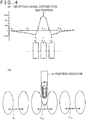
- FIG. 4(A) is a graph indicating a result of measurement of a signal level (voltage value) of a reception signal at each of the loop coils X 0 to X n of the loop coil group 15X when the position indicator 20 is positioned on the 13th loop coil X 12 from the left end of the loop coil group 15X.
- FIG. 4(B) is a view illustrating a case in which a predetermined signal is transmitted through the selected loop coil.
- the axis of abscissa indicates the position of the loop coils of the loop coil group 15X and the axis of ordinate indicates the signal level of the reception signal received by the loop coils.
- the signal level of a reception signal at the loop coil X 12 just below the position indicator 20 is highest, and the signal level of the reception signal decreases as the distance from the loop coil X 12 increases.
- the signal level of the reception signal does not decrease linearly as the distance from the loop coil X 12 just below the position indicator 20 at which the signal level of the reception signal is highest increases.
- the signal level of the reception signal first decreases to a value proximate to "-400" at the loop coils X 9 and X 15 which neighbor with the loop coil X 12 just below the position indicator 20 at which the signal level of the reception signal is highest. Then, as the distance from the loop coil X 12 increases, the signal level gradually increases and finally converges to a value proximate to "0.”
- the signal level of the reception signal is highest at the loop coil X 12 just below the position indicator 20, and a main lobe is formed in a region including the loop coils X 10 , X 11 , X 12 , X 13 and X 14 .
- side lobes whose signal level indicates the opposite direction (negative direction) to that of the main lobe are formed.
- One of the side lobes is formed such that a vertex in the negative direction is indicated at the loop coil X 9
- the other one of the side lobes is formed such that a vertex in the negative direction is indicated at the loop coil X 15 .
- a signal (first signal) from the transmission signal generation circuit 110 is supplied, and to the loop coils X 9 and X 15 at which the reception signal indicates the lowest signal level, a signal (second signal) of the opposite phase to that of the first signal is supplied, the second signal being obtained by inverting the phase of the first signal from the transmission signal generation circuit 110. Consequently, a signal flowing to the loop coil X 12 just below the position indicator 20 and signals flowing to the loop coils X 9 and X 15 at which the signal level of the reception signal is lowest flow in the opposite directions to each other as depicted on the lower side in the graph of FIG. 4(A) .
- the directions of magnetic fields generated in loop coils adjacent each other become same as each other, and cancellation of the induced magnetic field generated in the loop coil X 12 and the induced magnetic fields generated in the loop coils X 9 and X 15 can be prevented. Accordingly, in comparison with an alternative case in which a signal is supplied only from the loop coil X 12 just below the position indicator 20 at which the signal level of the reception signal is highest, the signal to be supplied to the position indicator 20 can be increased significantly.
- the position indicator 20 can receive signals supplied not only from the loop coil X 12 but also from the loop coil X 9 or the loop coil X 15 . Accordingly, supply of a signal to be supplied to the position indicator 20 can be increased significantly in comparison with that in the prior art.
- each of the loop coils X 0 to X n of the loop coil group 15X has a phase inversion circuit 1X(1), 1X(2), ... and a switch circuit 2X(1), 2X(2), ... provided therein.
- each of the loop coils Y 0 to Y m of the loop coil group 15Y has a phase inversion circuit 1Y(1), 1Y(2),... and a switch circuit 2Y(1), 2Y(2), ... provided therein.
- phase inversion circuit 1X each of the phase inversion circuits 1X(1), 1X(2), ... is referred to as phase inversion circuit 1X
- switch circuit 2X each of the switch circuits 2X(1), 2X(2), ... is referred to as switch circuit 2X.
- phase inversion circuit 1Y each of the phase inversion circuits 1Y(1), 1Y(2), ... is referred to as phase inversion circuit 1Y
- switch circuit 2Y each of the switch circuits 2Y(1), 2Y(2), ... is referred to as switch circuit 2Y.
- the switch circuits 2X and 2Y in the present example are switch circuits which include terminals a and b and can be placed into a state in which the loop coil is not connected to the movable terminal of the transmission-reception switching circuit 102 without being switched to the terminal a or b or any of the terminals under the control of the process controlling unit 130.
- the selection circuit 101 switches the switch circuit 2X connected to the loop coil just below the position indicator 20 to the terminal a side and switches the switch circuits 2X each connected to the loop coil at which the signal level of the reception signal is lowest to the terminal b side.
- a first signal from the transmission signal generation circuit 110 is supplied to the loop coil just below the position indicator 20 while the first signal after inverted in phase by the phase inversion circuit 1X is simultaneously supplied to the loop coil at which the signal level of the reception signal is lowest. Accordingly, a second signal of a phase inverted from that of the first signal is supplied to the loop coil at which the signal level of the reception signal is lowest.
- a signal is transmitted from each of the loop coil just below the position indicator 20 and a loop coil at which the signal level of the reception signal is lowest to the position indicator 20 such that the signals do not cancel each other.
- each loop coil of the loop coil group 15X is connected to the movable terminal M of the transmission-reception switching circuit 102, and detection of a position indicated by the position indicator 20 is performed.
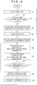
- the process controlling unit 130 executes a process of controlling the selection circuit 101 to successively select the loop coils X 0 to X n of the loop coil group 15X and controlling the transmission-reception switching circuit 102 to repeat supply of a signal to the loop coil selected by the selection circuit 101 and reception of a signal by the selected loop coil to detect a loop coil at which the received signal indicates the highest signal level (step S1).
- the process at step S1 is hereinafter referred to as X-axis global scan.
- the process controlling unit 130 controls the control circuit 101 to switch, for example, the switch circuit 2X(1) connected to the first loop coil X 0 within the loop coil group 15X to the terminal a side thereby to connect the loop coil X 0 to the movable terminal M of the transmission-reception switching circuit 102 and simultaneously controls the transmission-reception switching circuit 102 to cause the movable terminal M to select the transmission side terminal T thereby to transmit a signal of the frequency f0 supplied thereto from the transmission signal generation circuit 110 to the loop coil X 0 .
- the process controlling unit 130 controls the transmission-reception switching circuit 102 to cause the movable terminal M to select the reception side terminal R to supply a signal from the position indicator 20 received through the loop coil X 0 to the reception signal processing circuit 120 to detect the signal level of the reception signal.
- the process controlling unit 130 performs such signal transmission and reception processes for each of the loop coils X 0 to X n which configure the loop coil group 15X to specify whether the position indicator 20 is in the proximity of or in contact with the indication inputting face 13A and specify, where the position indicator 20 is in the proximity or in contact, a loop coil in the X-axis direction just below the position indicator 20.
- step S2 decides whether or not there exists a loop coil at which the signal level (voltage value) of the reception signal is equal to or higher than a fixed value (step S2).
- the decision process at step S2 is a process for deciding whether or not the position indicator 20 is within an effective reading height of the position detection apparatus 10N. If it is decided by the decision process at step S2 that there exists no loop coil at which the signal level of the reception signal is equal to or higher than the fixed value, then since this is a state in which the position indicator 20 is neither in the proximity of nor in contact with the indication inputting face 13A, the process controlling unit 130 repeats the processes at the steps beginning with step S 1.
- the process controlling unit 130 extracts (specifies), on the basis of the result of the process at step S1, a peak coil at which the signal level of the reception signal is highest and a bottom coil at which the signal level of the reception signal is lowest from among the loop coils of the loop coil group 15X and stores coil numbers of the extracted coils (step S3).
- a peak coil at which the signal level of the reception signal is highest and a bottom coil at which the signal level of the reception signal is lowest from among the loop coils of the loop coil group 15X and stores coil numbers of the extracted coils (step S3).
- the process controlling unit 130 executes a process of controlling the selection circuit 101 to successively select the loop coils Y 0 to Y m of the loop coil group 15Y and controlling the transmission-reception switching circuit 102 to repeat supply of a signal to the loop coil selected by the selection circuit 101 and reception of a signal by the selected loop coil to detect a loop coil at which the received signal indicates a high signal level (step S4).
- the process at step S4 is hereinafter referred to as Y-axis global scan.
- the process controlling unit 130 first controls the selection circuit 101 to switch, for example, the switch circuit 2Y(1) connected to the first loop coil Y 0 from within the loop coil group 15Y to the terminal a side thereby to connect the loop coil Y 0 to the movable terminal M of the transmission-reception switching circuit 102 and simultaneously controls the transmission-reception switching circuit 102 to cause the movable terminal M to select the transmission side terminal T thereby to transmit a signal of the frequency f0 supplied from the transmission signal generation circuit 110 to the loop coil Y 0 .
- the process controlling unit 130 controls the transmission-reception switching circuit 102 to cause the movable terminal M to select the reception side terminal R thereby to supply a signal from the position indicator 20 received through the loop coil Y 0 to the reception signal processing circuit 120 to detect the signal level of the reception signal.
- the process controlling unit 130 performs such signal transmission and reception processes as described above for the loop coils Y 0 to Y m configuring the loop coil group 15Y to specify whether the position indicator 20 is in the proximity of or in contact with the indication inputting face 13A and specify, where the position indicator 20 is in the proximity or in contact, a loop coil in the Y-axis direction just below the position indicator 20.
- the process controlling unit 130 extracts (specifies), on the basis of the result of the process at step S4, a peak coil at which the signal level of the reception signal is highest and a bottom coil at which the signal level of the reception signal is lowest from among the loop coils of the loop coil group 15Y and stores coil numbers of the extracted coils (step S5).
- a decision process corresponding to the process at step S2 described hereinabove is not performed after the Y-axis global scan is that, at a stage of the process at step S4, it is decided by the decision process at step S2 that the position indicator 20 is within the effective reading height of the position detection apparatus 10N and there is no necessity to perform a decision again.
- the process controlling unit 130 may not select all loop coils of the loop coil groups 15X and 15Y but may select the loop coils in a thinning out manner such that it selects every other loop coil or every third loop coil.
- transmission and reception of a signal to and from one loop coil may be performed by a plural number of times.
- transmission time periods for the individual loop coils and reception time periods for the individual loop coils must individually be equal to each other, the transmission time periods and the reception time periods may not necessarily be equal to each other.
- the process controlling unit 130 performs X-axis sector scan which is a process of performing transmission and reception of signals to and from a predetermined number of loop coils, for example, five loop coils, centered at the peak coil from within the loop coil group 15X and neighboring with the peak coil (step S6).
- X-axis sector scan which is a process of performing transmission and reception of signals to and from a predetermined number of loop coils, for example, five loop coils, centered at the peak coil from within the loop coil group 15X and neighboring with the peak coil.
- the process controlling unit 130 switches the loop coils (in the present example, five loop coils) in an ascending order (or a descending order) of the coil numbers.
- the position indicated by the position indicator 20 can be specified accurately in the proximity of the peak coil.
- the process controlling unit 130 performs Y-axis sector scan which is a process of performing transmission and reception of signals to and from a predetermined number of loop coils, for example, five loop coils, centered at the peak coil from within the loop coil group 15Y and neighboring with the peak coil (step S7).
- Y-axis sector scan which is a process of performing transmission and reception of signals to and from a predetermined number of loop coils, for example, five loop coils, centered at the peak coil from within the loop coil group 15Y and neighboring with the peak coil.
- the process controlling unit 130 controls the selection circuit 101 such that switching to the terminal a side is performed for the switch circuit 2Y connected to the peak coil and switching to the terminal b side is performed for the switch circuits 2Y connected to the bottom coils.
- a signal according to the signal (first signal) from the transmission signal generation circuit 110 is transmitted from the peak coil, and a signal according to a signal (second signal) having a phase inverted from that of the signal (first signal) from the transmission signal generation circuit 110 is transmitted from each of the bottom coils. Accordingly, a signal can be supplied to the position indicator 20 preventing such a situation that a signal transmitted from the peak coil and signals transmitted from the bottom coils cancel each other.
- the process controlling unit 130 switches the loop coils (in the present example, five loop coils) in an ascending order (or a descending order).
- the position indicated by the position indicator 20 can be specified accurately in the proximity of the peak coil.
- the process controlling unit 130 decides whether or not the highest values of the signal levels of the reception signal obtained by the processes at steps S6 and S7 are equal to or higher than a fixed value set in advance (step S8).
- the decision process at step S8 is a process for deciding whether or not the position indicator 20 is within the effective reading height of the position detection apparatus 10N.
- the process controlling unit 130 extracts (specifies), on the basis of the results of the processes of the X-axis sector scan at step S6 and the Y-axis sector scan at step S7, a peak coil and bottom coils in each of the loop coil group 15X and the loop coil group 15Y.
- bottom coils corresponding to the peak coil extracted at step S9 are extracted (specified) on the basis of the positional relationship between the peak coil and the bottom coils extracted by the processes at steps S1 to S5.
- the bottom coils corresponding to the peak coil are loop coils at positions spaced by a three-coil distance forwardly and rearwardly from the peak coil. Therefore, at step S9, if the peak coil is extracted, then on the basis of the positional relationship between the peak coil and the bottom coils extracted by the processes at steps S1 to S5, loop coils at positions spaced, for example, by a three-coil distance forwardly and rearwardly from the peak coil are extracted (specified) as the bottom coils.
- the process controlling unit 130 calculates, on the basis of the position of the peak coil of the loop coil group 15X and the position of the peak coil of the loop coil group 15Y extracted at step S9, coordinate values indicative of the position indicated on the indication inputting face 13A by the position indicator 20 (step S10).
- the coordinate values calculated here are supplied to the LCD controller not depicted provided on the mother board MB or the like and are used for display control and so forth.
- the process controlling unit 130 repeats the processes at the steps beginning with step S6.
- a peak coil and bottom coils are extracted by the X-axis global scan and the Y-axis global scan.
- a peak coil and bottom coils from which a signal is to be transmitted are specified on the basis of a reception signal distribution on the sensor unit 13 of a reflection signal transmitted from the position indicator 20.
- a signal transmitted from the peak coil and signals transmitted from the bottom coils can be transmitted such that they do not cancel each other. Consequently, a signal to be supplied from the sensor unit 13 to the position indicator 20 can be increased. Besides, there is no necessity to upsize the loop coils of the sensor unit 13 or to drive the transmission signal generation circuit with a high voltage or high current.
- FIGS. 7 and 8 A configuration of an electronic apparatus 10A of a second embodiment is described with reference to FIGS. 7 and 8 .
- the electronic apparatus 10 of the present example is a high function mobile phone terminal called smartphone similarly to the electronic apparatus 10 of the first embodiment.
- an electronic apparatus 10A is exemplified which includes, in addition to the sensor unit 13 disposed in an overlapping relationship with the display screen 12, auxiliary inputting units 14A and 14B provided in a peripheral region of the display screen 12 and having, for example, a touch sensor function.
- the auxiliary inputting units 14A and 14B include corresponding loop coil 16A or 16B provided thereon, respectively.
- the electronic apparatus 10A of the second embodiment is configured substantially similarly to the electronic apparatus 10 of the first embodiment. Therefore, in FIGS. 7 to 12 with reference to which the electronic apparatus 10A of the second embodiment is described, like or corresponding elements to those in the electronic apparatus 10 of the first embodiment described hereinabove with reference to FIGS. 1 to 6 are denoted by the same reference symbols, and overlapping detailed description of them is omitted herein to avoid redundancy.
- the electronic apparatus 10A of the second embodiment includes the auxiliary inputting units 14A and 14B provided in a region different from that of the display screen 12 but positioned in the proximity of the display screen 12 on one side (left side in FIG. 7 ) in a longitudinal direction (X-axis direction) of the housing 11.
- the auxiliary inputting units 14A and 14B are configured such that, for example, a capacitive sensor is disposed therein, and a specific function having a high use frequency such as a menu displaying function or a canceling function of each application is allocated to each of the auxiliary inputting units 14A and 14B.
- an auxiliary sensor unit 16 of the electromagnetic induction type same as that of the sensor unit 13 is provided as depicted in FIG. 7(B) .
- the auxiliary sensor unit 16 includes the loop coils 16A and 16B corresponding to the auxiliary inputting units 14A and 14B, respectively.
- the loop coils 16A and 16B of the auxiliary sensor unit 16 may each be formed from a transparent conductor on a transparent substrate, since the auxiliary sensor unit 16 is not overlapped with the display screen 12, the loop coils 16A and 16B may be formed from an opaque conductor on an opaque substrate.
- the position detection apparatus 10X is configured such that the sensor unit 13 and the auxiliary sensor unit 16 are connected through a connector unit not depicted to a sensor controller 100A provided on the mother board MB.
- the sensor controller 100A configures a control circuit for the position detection apparatus 10X.
- FIG. 8 also a circuit configuration of the position indicator 20 used for inputting to the sensor unit 13 and the auxiliary sensor unit 16 which are sensors of the electromagnetic induction type is depicted.
- the position indicator 20 is same as the position indicator 20 in the first embodiment.
- the sensor controller 100A performs control similar to that of X-axis global scan, Y-axis global scan, X-axis sector scan and Y-axis sector scan in the first embodiment for a plurality of loop coils X 0 to X n and a plurality of loop coils Y 0 to Y m of the loop coil groups 15X and 15Y of the sensor unit 13 similarly to the sensor controller 100 in the electronic apparatus 10 of the first embodiment and controls a detection process of the position indicator 20 using the two loop coils 16A and 16B of the auxiliary sensor unit 16.
- the sensor controller 100A performs, from results of the X-axis global scan, Y-axis global scan, X-axis sector scan and Y-axis sector scan in the sensor unit 13, a detection process of a position indicated by the position indicator 20 on the indication inputting face 13A. Further, the sensor controller 100A performs, from a result of detection regarding the two loop coils 16A and 16B provided on the auxiliary sensor unit 16, a detection process of whether or not the position indicator 20 is detected by one of the auxiliary inputting units 14A and 14B.
- the sensor controller 100A controls the sensor unit 13 to perform global scan for all of the loop coils X 0 to X n and Y 0 to Y m of the sensor unit 13 and controls the auxiliary sensor unit 16 to perform a detection process alternately for the loop coils 16A and 16B at predetermined time intervals.
- the sensor controller 100A controls the sensor unit 13 to perform X-axis sector scan and Y-axis sector scan by a plurality of loop coils in the proximity of the detected position of the position indicator 20 and controls the auxiliary sensor unit 16, in the present example, to stop detection of the position indicator 20.
- the sensor controller 100A alternately scans the loop coils 16A and 16B at predetermined time intervals. In this case, the sensor controller 100A controls the sensor unit 13 to stop detection of the position indicator 20. It is to be noted that detection may be partly performed at a predetermined speed only with regard to loop coils in an area of a peripheral edge portion of the sensor unit 13 in the proximity of the auxiliary sensor unit 16.
- the position detection apparatus 10X is configured from the sensor unit 13, the auxiliary sensor unit 16 and the sensor controller 100A, and the position detection apparatus 10X and the position indicator 20 configure an inputting apparatus (inputting device) of the electronic apparatus 10.
- the sensor switching circuit 103 is a circuit for selectively supplying a signal supplied thereto from the transmission signal generation circuit 110 to the sensor unit 13 and the auxiliary sensor unit 16 under the control of the process controlling unit 130A.
- the sensor switching circuit 103 is connected at a movable terminal M thereof to the output terminal of the transmission signal generation circuit 110 and connected at a terminal D thereof to the transmission side terminal T of the transmission-reception switching circuit 102 while it is connected at a terminal K thereof to the transmission side terminals T of the transmission-reception switching circuits 102 and 105.
- the sensor switching circuit 104 is a circuit for selectively connecting the sensor unit 13 or the auxiliary sensor unit 16 to the reception signal processing circuit 120 at the succeeding stage under the control of the process controlling unit 130A.
- the sensor switching circuit 104 has one movable terminal M and terminals K and D, and is connected at the movable terminal M thereof to the input terminal of the reception signal processing circuit 120, at the terminal D thereof to the reception side terminal R of the transmission-reception switching circuit 102 and at the terminal K thereof to the reception side terminal R of the transmission-reception switching circuit 105.
- the transmission-reception switching circuit 105 switches the connection destination (transmission side terminal T or reception side terminal R) to which the loop coil selected by the selection circuit 106 is to be connected after every predetermined time period under the control of the process controlling unit 130A such that switching between transmission and reception is performed time-divisionally similarly as in the transmission-reception switching circuit 102.
- the process controlling unit 130A is a circuit for controlling the components of the sensor controller 100A.
- the process controlling unit 130A performs selection control of a loop coil by the selection circuit 101 and the selection circuit 106 and performs switching control of the sensor switching circuit 103 and the sensor switching circuit 104 and switching control of the transmission-reception switching circuit 102 and the transmission-reception switching circuit 105.
- the process controlling unit 130A performs by the sensor unit 13 a detection process of a position indicated by the position indicator 20 and performs by the auxiliary sensor unit 16 a detection process of the position indicator 20.
- the process controlling unit 130A switches the sensor switching circuit 103 and the sensor switching circuit 104 to the terminal D side. Consequently, the output terminal of the transmission signal generation circuit 110 is connected to the transmission side terminal T of the transmission-reception switching circuit 102 through the sensor switching circuit 103, and the reception side terminal R of the transmission-reception switching circuit 102 is connected to the input terminal of the reception signal processing circuit 120 through the sensor switching circuit 104.
- the transmission-reception switching circuit 102 selects the transmission side terminal T (upon transmission)
- an AC signal from the current driver 112 is supplied to the loop coil selected by the selection circuit 101. Consequently, to the loop coil selected by the selection circuit 101 from within the loop coil group 15X or the loop coil group 15Y, the signal from the transmission signal generation circuit 110 is supplied, and from the loop coil, the signal is sent out.
- the resonance circuit of the position indicator 20 receives supply of the signal sent out from the loop coil and accumulates energy.
- the transmission-reception switching circuit 102 selects the reception side terminal R (upon reception)
- a signal according to the induced voltage generated in the loop coil selected by the selection circuit 101 is supplied to the reception signal processing circuit 120. Consequently, in the loop coils of the loop coil group 15X and the loop coil group 15Y, when the position indicator 20 indicates a position on the sensor unit 13, an induced voltage is generated by a reflection signal transmitted from the position indicator 20.
- a signal from the loop coil of the loop coil group 15X or the loop coil group 15Y selected by the selection circuit 101 is supplied to the reception signal processing circuit 120, and the signal level of the reception signal is detected and used for calculation of the indicated position.
- the process controlling unit 130A switches the sensor switching circuit 103 and the sensor switching circuit 104 to the terminal K side. Consequently, the output terminal of the transmission signal generation circuit 110 is connected to the transmission side terminals T of the transmission-reception switching circuits 102 and 105 through the sensor switching circuit 103. Further, the reception side terminals R of the transmission-reception switching circuits 102 and 105 are connected to the input terminal of the reception signal processing circuit 120 through the sensor switching circuit 104.
- the selection circuit 106 alternately selects the loop coils 16A and 16B under the control of the process controlling unit 130A. Then, when the selection circuit 106 selects the loop coil 16A, the transmission-reception switching circuit 105 is controlled for switching by the process controlling unit 130A to perform transmission of a signal and reception of a signal from the position indicator 20. Similarly, when the selection circuit 106 selects the loop coil 16B, the transmission-reception switching circuit 105 is controlled for switching under the control of the process controlling unit 130A to perform transmission of a signal and reception of a signal from the position indicator 20. In this manner, transmission and reception of a signal are performed through the loop coils 16A and 16B, and it is detected through which one of the loop coils a signal from the position indicator 20 is received.
- FIGS. 9 and 10 are views illustrating a process performed when a signal is transmitted from the loop coil 16A or 16B.
- the process controlling unit 130A measures the signal level of the reception signal of each loop coil of the auxiliary sensor unit 16 and the sensor unit 13.
- the reception signal distribution on the sensor coils is, for example, such as indicated by a graph of a reception signal distribution depicted on the lower side in FIG. 9 similarly as in the case of the first embodiment ( FIG. 4 ).
- the signal level of the reception signal is highest at the loop coil 16A or 16B of the auxiliary sensor unit 16, and the signal level of the reception signal of the loop coil X 0 of the loop coil group 15X adjacent the loop coil 16A or 16B is lowest.
- the signal level of the reception signal gradually rises as the distance from the loop coil 16A or 16B at which the signal level of the reception signal is lowest increases until the level value converges in the proximity of "0.”
- the position detection apparatus 10X of the present example if the position indicator 20 is detected by the auxiliary sensor unit 16, then a signal is transmitted from the loop coil 16A or 16B and the loop coil X 0 of the loop coil group 15X.
- the direction of an induced magnetic field generated in the loop coil X 0 of the loop coil group 15X is opposite to the direction of an induced magnetic field generated in the loop coil 16A or 16B, then the induced magnetic fields cancel each other.
- a signal from the transmission signal generation circuit 110 is supplied as it is, and a signal according to this is transmitted to the position indicator 20.
- a signal from the transmission signal generation circuit 110 is inverted in phase such that a signal of an opposite phase to that of the signal from the transmission signal generation circuit 110 is supplied to the loop coil X 0 of the loop coil group 15X, and a signal according to this is transmitted to the position indicator 20. Consequently, as depicted in FIG.
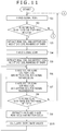
- steps S1 to S10 depicted in FIG. 11 are similar to the processes performed at the corresponding steps depicted in FIG. 6 .
- the processes at steps S1 to S10 depicted in FIG. 11 are a detection process by the sensor unit 13. Therefore, description of steps S 1 to S10 of FIG. 11 is omitted herein because it overlaps with the description regarding FIG. 6 .
- the process controlling unit 130A of the position detection apparatus 10X of the second embodiment advances its processing to a process at step S21 of FIG. 12 .
- the process controlling unit 130A controls the components to perform a detection process by the auxiliary sensor unit 16 (step S21).
- transmission of a signal is performed using not only the loop coil 16A or the loop coil 16B of the auxiliary sensor unit 16 but also the loop coil X 0 of the loop coil group 15X. Consequently, a signal can be supplied efficiently to the position indicator 20.
- the process controlling unit 130A decides whether or not the signal level (voltage value) of the reception signal of the loop coil 16A or the loop coil 16B is equal to or higher than a fixed value (step S22).
- the decision process at step S22 is a process for deciding whether or not the position indicator 20 is positioned within the effective reading height of the auxiliary sensor unit 16.
- step S22 If it is decided by the decision process at step S22 that there exists no loop coil at which the signal level of the reception signal is equal to or higher than the fixed value, then since the position indicator 20 is neither in the proximity of nor in contact with the auxiliary sensor unit 16, the process controlling unit 130A returns the processing to step S 1 to repeat the processes at the steps beginning with step S 1.
- step S23 If it is decided by the decision process at step S22 that there exists a loop coil at which the signal level of the reception signal is equal to or higher than the fixed value, then it is decided whether the loop coil just below the position indicator 20 is the loop coil 16A or the loop coil 16B (step S23).
- the process at step S23 is a process for specifying which one of the auxiliary inputting unit 14A and the auxiliary inputting unit 14B is selected.
- the position detection apparatus 10X incorporated in the electronic apparatus 10A of the second embodiment can supply sufficient energy to the position indicator 20 also upon a detection process by the auxiliary sensor unit 16. Accordingly, the loop coils 16A and 16B of the auxiliary sensor unit 16 are not upsized, and there is no necessity to upsize the transmission signal generation circuit either.
- a signal from the transmission signal generation circuit 110 is supplied as it is to a peak coil while a signal obtained by inverting the phase of the signal from the transmission signal generation circuit 110 is supplied to a bottom coil.
- the present invention is not limited to this if a signal to be transmitted from a peak coil and a signal to be transmitted from a bottom coil can be transmitted such that they do not cancel each other.
- a bottom coil is wound in the opposite direction to that of a peak coil, then sufficient energy can be supplied to the position indicator 20 without inverting the phase of a signal to be supplied to a bottom coil.
- FIG. 13 A particular example in which a counter wound coil is used is described with reference to FIG. 13 .
- description is given exemplifying a case in which, as depicted in FIG. 13(A) , the auxiliary sensor unit 16 is provided in addition to the sensor unit 13 similarly as in the case of the position detection apparatus 10X of the second embodiment described hereinabove and the loop coil 16A or 16B of the auxiliary sensor unit 16 is positioned just below the position indicator 20 such that the loop coil 16A or 16B serves as a peak coil and the loop coil X 0 of the sensor unit 13 serves as a bottom coil.
- the winding direction of the bottom coil X 0 is set to the opposite direction to that of the loop coils 16A and 16B each serving as a peak coil as depicted in FIG. 13(A) . If the winding directions are set in this manner, then the direction of a magnetic field to be generated by the loop coil X 0 is set to a direction same as that of magnetic fields to be generated by the loop coils 16A and 16B such that the magnetic fields do not cancel each other without supplying a signal having an inverted phase to the loop coil X 0 serving as a bottom coil as depicted in FIG. 13(B) .
- the sensor unit 13 is configured from the loop coil group 15X and the loop coil group 15Y each configured from a plurality of loop coils.
- the loop coils X 0 to X n of the loop coil group 15X and the loop coils Y 0 to Y m of the loop coil group 15Y are each connected at one end thereof to the selection circuit 101 and grounded at the other end thereof.
- a selection circuit may be provided so as to switch, with regard to a loop coil which is to serve as a bottom coil, an end portion to be connected to the selection circuit 101 and another end portion to be grounded in a reverse relationship to that of a loop coil which is to serve as a peak coil.
- the loop coils configuring the loop coil group 15X and the loop coils configuring the loop coil group 15Y are each formed by winding an electrode, for example, by one turn, two turns or three turns.
- the loop coils 16A and 16B of the auxiliary sensor unit 16 are each formed by winding an electrode. The number of turns of the loop coils can be set suitably.
- the electrodes used to configure the sensor units 13 and 16 are not limited to loop coils. If a signal whose phase is inverted is supplied as in the case of the second embodiment, then the present invention can be applied also where a plurality of single electrodes (single conductors) are used to configure the sensor unit 13 and the auxiliary sensor unit 16.
- a loop coil at which the signal level of the reception signal is lowest may be selected as a bottom coil.
- a loop coil determined on the basis of a signal level at which the signal level of a reflection signal received from the position indicator 20 by a loop coil (electrode) configuring the sensor unit 13 and the auxiliary sensor unit 16 is lowest may be selected as a bottom coil.
- the sensor unit 13 is disposed in an overlapping relationship on the display screen 12 of an LCD unit, the position at which the sensor unit 13 is to be disposed is not limited to this.
- the sensor unit 13 may be provided on the lower side of the LCD unit (on the face side opposite to the display screen 12).
- a signal of a phase opposite to that of a signal to be supplied to the loop coil X 0 may be supplied not only to the loop coil X 3 of the loop coil group 15X, which serves as a bottom coil, but also, for example, to the loop coil 16A or the loop coil 16B of the auxiliary sensor unit 16.
- a phase inversion circuit may be provided in the selection circuit 106 such that one of a signal supplied from the transmission signal generation circuit 110 and a signal obtained by inverting the phase of the signal supplied from the transmission signal generation circuit 110 can be selected so as to be supplied to the loop coil 16A or 16B. It is to be noted that, as described hereinabove with reference to FIG. 13 , if the winding directions of the loop coils 16A and 16B of the auxiliary sensor unit 16 and the loop coils of the sensor unit 13 are opposite to each other, then there is no necessity to provide the phase inversion circuit in the selection circuit 106.
- the inputting apparatus configured from the position indicator 20 and the position detection apparatus 10N or 10X specifies a peak coil and a bottom coil upon global scan and a signal is transmitted from both of the peak coil and the bottom coil based on the specification.
- the present invention need not specify a bottom coil every time global scan is performed.
- global scan for specifying a peak coil and a bottom coil may be performed as test scan such that a bottom coil is specified mechanically in accordance with the relationship between the peak coil and the bottom coil specified by the test scan. For example, if it is decided based on the test scan that a peak coil and a bottom coil are positioned in a spaced relationship by a three-coil distance from each other, then a signal may always be supplied to a coil spaced by a three-coil distance from a peak coil as a bottom coil.
- the functions of the sensor unit of the detection apparatus are implemented by the sensor unit 13 of the position detection apparatus 10N. Further, the functions of the signal supplying circuit of the detection apparatus are, in the detection apparatus 10N, implemented by a section including the oscillator 111, current driver 112, transmission-reception switching circuit 102 and selection circuit 101 and are, in the detection apparatus 10X, implemented by a section including the oscillator 111, current driver 112, sensor switching circuit 103, transmission-reception switching circuit 102 and selection circuit 101.
- the functions of the detection circuit of the detection apparatus are implemented principally by the reception signal processing circuit 120 and the process controlling unit 130 of the position detection apparatus 10N or by the reception signal processing circuit 120 and the process controlling unit 130A of the position detection apparatus 10X. Further, the functions of the control circuit of the detection apparatus are implemented by the process controlling unit 130 of the position detection apparatus 10N and the process controlling unit 130 of the position detection apparatus 10X.
- phase inversion circuit of the detection apparatus are implemented by the phase inversion circuits 1X and 1Y provided in the selection circuit 101 of the position detection apparatus 10N and 10X.
- the functions of the switch circuit of the position detection apparatus are implemented by the switch circuits 2X and 2Y provided in the selection circuit 101 of the position detection apparatus 10N and 10X.
- the functions of the first and second signal generation circuits of the detection apparatus are implemented by the phase inversion circuits 1X and 1 Y and the switch circuits 2X and 2Y provided in the selection circuit 101 of the position detection apparatus 10N and 10X.
- the functions of the first sensor unit of the detection apparatus are implemented by the sensor unit 13 of the position detection apparatus 10X, and the functions of the second sensor unit of the detection apparatus are implemented by the auxiliary sensor unit 16 of the position detection apparatus 10X.
- the method described with reference to the flow charts of FIGS. 6 , 12 and 13 is a method corresponding to an embodiment of the detection method according to the present invention.
- the apparatus configured from the position indicator 20 and the position detection apparatus 10N is an inputting apparatus applied to the electronic apparatus 10.
- an apparatus configured from the position indicator 20 and the position detection apparatus 10X is an inputting apparatus applied to the electronic apparatus 10A.
- 10 Electronic apparatus, 11 ... Housing, 11A ... Upper side housing, 11B ... Lower side housing, 12 ... Display screen, 13 ... Sensor unit, 13A ... Indication inputting face, 15X ... Loop coil group, X 0 to X n ... Loop coil, 15Y ... Loop coil group, Y 0 to Y m ... Loop coil, MB ... Mother board, 10N ... Position detection apparatus, 101 ... Selection circuit, 1X(1), 1X(2) ... Phase inversion circuit, 2X(1), 2X(2) ... Switch circuit, 1Y(1), 1Y(2) ... Phase inversion circuit, 2Y(1), 2Y(2) ... Switch circuit, 102 ... Transmission-reception switching circuit, 110 ... Transmission signal generation circuit, 111 ...
Landscapes
- Engineering & Computer Science (AREA)
- General Engineering & Computer Science (AREA)
- Theoretical Computer Science (AREA)
- Physics & Mathematics (AREA)
- Human Computer Interaction (AREA)
- General Physics & Mathematics (AREA)
- Electromagnetism (AREA)
- Near-Field Transmission Systems (AREA)
- Position Input By Displaying (AREA)
Abstract
Description
- The present invention relates to a detection apparatus of the electromagnetic induction type, an inputting apparatus configured from the detection apparatus and an indicator, and a detection method for use with the detection apparatus.
- An inputting apparatus of the electromagnetic induction type is used as an inputting device for an electronic apparatus such as a tablet type terminal or a high function mobile phone terminal called smartphone or the like. This inputting apparatus is configured from a position indicator formed in a pen shape, and a position detection apparatus having an inputting face for which a pointing operation or inputting of characters, figures and so forth is performed using the position indicator. The position indicator includes a resonance circuit formed from a coil and a capacitor. Meanwhile, the position detection apparatus includes a sensor unit in which a loop coil group including a plurality of loop coils disposed in a transverse direction (X-axis direction) and another loop coil group including a plurality of loop coils disposed in a longitudinal direction (Y-axis direction) are stacked.
- In the position detection apparatus, detection of a position indicated is performed briefly by such operations as described below. First, in the position detection apparatus, one loop coil is selected in a predetermined order from among the plurality of loop coils disposed on the sensor unit, and a transmission signal is transmitted from the selected loop coil to the position indicator. Consequently, the capacitor of the position indicator is charged. Then, the loop coil used for the transmission is connected to a reception circuit to receive a signal transmitted from the resonance circuit of the position indicator, and detection of the indicated position is performed on the basis of the received signal. By performing such transmission and reception of a signal successively switching the loop coil, the position indicated by the position indicator on the sensor unit is detected.
- It is to be noted that, in
Patent Document 1 hereinafter mentioned, an invention relating to an inputting apparatus of the electromagnetic induction type is disclosed. For an inputting apparatus of the electromagnetic induction type, various improvements have been made, and an operation method (scanning method) for coils configuring a sensor unit is disclosed, for example, inPatent Document -
- Patent Document 1:
Japanese Patent Laid-Open No. Hei 07-044304 - Patent Document 2:
Japanese Patent Laid-Open No. Hei 08-286814 - Patent Document 3:
Japanese Patent Laid-Open No. 2000-231443 - In a conventional inputting apparatus of the electromagnetic induction type, one loop coil in a loop coil group, for example, for the X-axis direction positioned just below a position indicator is used to transmit a transmission signal from a position detection apparatus to the position indicator. If a transmission signal is transmitted from a loop coil just below the position indicator, then since the signal level of a signal received by the position indicator is high, a capacitor of a resonance circuit can be charged efficiently.
- However, if it is tried to transmit a transmission signal of a high signal level using one loop coil, then it is necessary to drive the transmission circuit with a high voltage or high current or to continue transmission of a transmission signal for a long period of time, and this may give rise to increase of the scale of the transmission circuit or increase of the current consumption. Further, where one loop coil just below the position indicator is used to transmit a transmission signal to the position indicator, if the size of the loop coil is small, then it fails to transmit a transmission signal of a sufficiently high signal level to the position indicator.
- Therefore, it seems a possible idea to use a method of transmitting, using two loop coils individually belonging to a loop coil group for an X-axis direction and a loop coil group for a Y-axis direction and positioned just below a position indicator, transmission signals of the same phase at the same time to the position indicator. However, in the proximity of a bezel (frame) made of a metal, for example, of a front panel of the position detection apparatus, the bezel made of a metal sometimes shields part of a transmission signal transmitted from a loop coil in the proximity of the bezel. In this case, although a loop coil just below the position indicator is used, a transmission signal having a sufficient signal level cannot be provided to the position indicator.
- Further, in recent years, as an inputting apparatus of the electromagnetic induction type, also an inputting apparatus is provided which includes a sub sensor unit of a small region which implements a function, for example, as a button for switching a mode in addition to a main sensor unit. Since the sub sensor unit of a small region is small in area, a large loop coil cannot be disposed in the sub sensor unit, and also it is difficult to dispose a plurality of loop coils in the sub sensor unit. Therefore, where the sub sensor portion of the small region is to be indicated by the position indicator, a transmission signal of a sufficient signal level may not be able to be transmitted to the position indicator only from a loop coil just below the position indicator or a long period of time may be required to supply a sufficient transmission signal.
- Taking the foregoing into consideration, it is an object of the present invention to make it possible to provide a signal of an appropriate signal level to a position indicator even where, in an inputting apparatus of the electromagnetic induction type, a metal member which shields a transmission signal exists in the proximity of a loop coil or even where the loop coil is small.
- In order to solve the problems described above, the detection apparatus of the invention according to the present application is an indicator detection apparatus which transmits a signal to an indicator having a resonance circuit to cause the resonance circuit to resonate and receives a signal transmitted from the resonance circuit of the position indicator to detect the indicator, the detection apparatus including: a sensor unit configured from a plurality of electrodes for transmitting the signal to the indicator and receiving the signal from the indicator; a signal supplying circuit configured to supply a first signal to the sensor unit to cause each of the electrodes to generate a magnetic field to transmit a signal to the indicator thereby to cause the resonance circuit of the indicator to resonate; and a detection circuit configured to detect the signal from the resonance circuit of the indicator received by the plurality of electrodes configuring the sensor unit, wherein when the first signal is to be supplied, from among the electrodes, which receive the signal from the indicator, of the sensor unit, to a first electrode at which the signal from the indicator indicates the highest signal level, the signal supplying circuit supplies, to a second electrode at which the received signal has the lowest signal level, a signal with which a magnetic field generated by the second electrode is directed so as to strengthen a magnetic field generated by the first electrode.
- With the detection apparatus of the invention according to the present application, the sensor unit includes the plurality of electrodes, and the signal supplying circuit supplies the first signal to the sensor unit such that a magnetic field is generated from the electrodes of the sensor unit to transmit a signal to the indicator. Consequently, the resonance circuit of the indicator can be caused to resonate, and a signal is transmitted from the resonance circuit of the indicator to the sensor unit of the detection apparatus. The detection circuit detects the signal transmitted from the resonance circuit of the indicator and received by the plurality of electrodes configuring the sensor unit of the detection circuit itself.
- Then, the signal supplying circuit functions on the basis of a detection output from the detection circuit. When the first signal is to be supplied, from among the plurality of electrodes, which receive the signal transmitted from the resonance circuit of the indicator, of the sensor unit, to the first electrode at which the received signal indicates the highest signal level, the signal supplying circuit supplies a predetermined signal also to the second electrode. In this case, the second electrode is an electrode at which the received signal has the lowest signal level from among the electrodes of the sensor unit which receive the signal transmitted from the resonance circuit of the indicator. Further, the signal to be supplied to the second electrode is formed such that a magnetic field generated by the second electrode is directed so as to strengthen a magnetic field generated by the first electrode.
- Consequently, a signal according to the first signal can be transmitted to the indicator from the first electrode of the sensor unit which receives the signal from the indicator strongest, and further, a signal according to the second signal can be transmitted from the second electrode to the indicator. Since a signal can be transmitted from both of the first electrode and the second electrode to the indicator in this manner, a signal of an appropriate signal level can be provided to the indicator.
- According to the present invention, a signal of an appropriate signal level can be provided to the indicator even where, in the inputting apparatus of the electromagnetic induction type, a metal member which shields a transmission signal exists in the proximity of a loop coil or even where the loop coil is small.
-
- [
FIG. 1 ]
FIG. 1 is a view depicting an appearance and an example of a configuration of a sensor unit of anelectronic apparatus 10 of a first embodiment. - [
FIG. 2 ]
FIG. 2 is an exploded perspective view depicting an example of a configuration of theelectronic apparatus 10. - [
FIG. 3 ]
FIG. 3 is a block diagram depicting an example of a configuration of a position detection apparatus 10N. - [
FIG. 4 ]
FIG. 4 is a view illustrating selection of a loop coil from which a signal is to be transmitted to aposition indicator 20 and a signal transmitted through a selected loop coil. - [
FIG. 5 ]
FIG. 5 is a block diagram depicting an example of a configuration of aselection circuit 101 of the position detection apparatus 10N. - [
FIG. 6 ]
FIG. 6 is a flow chart illustrating a detection process of an indicated position executed by the position detection apparatus 10N. - [
FIG. 7 ]
FIG. 7 is a view depicting an example of an appearance and so forth of anelectronic apparatus 10A of a second embodiment. - [
FIG. 8 ]
FIG. 8 is a block diagram depicting an example of a configuration of a position detection apparatus 10X. - [
FIG. 9 ]
FIG. 9 is a view illustrating a process where a signal is transmitted from aloop coil - [
FIG. 10 ]
FIG. 10 is a view illustrating a process where a signal is transmitted from theloop coil - [
FIG. 11 ]
FIG. 11 is a flow chart illustrating a detection process of an indicated position executed by the position detection apparatus 10X. - [
FIG. 12 ]
FIG. 12 is a flow chart continued fromFIG. 11 . - [
FIG. 13 ]
FIG. 13 is a view depicting a particular example of a case in which a counter wound coil is used. - In the following, embodiments of an apparatus and a method according to the present invention are described with reference to the drawings. It is to be noted that, in the embodiments described below, a
position indicator 20 corresponds to an indicator in the claims, and each of position detection apparatus 10N and 10X corresponds to a detection apparatus in the claims. - A configuration of an
electronic apparatus 10 of a first embodiment is described with reference toFIGS. 1 and2 . - The
electronic apparatus 10 of the present example is a high function mobile phone terminal called smartphone, and as depicted inFIG. 1(A) , adisplay screen 12 of a display device configured, for example, from a liquid crystal display (LCD) unit is provided on one face side of ahousing 11 of a thin and flat substantially parallelepiped shape so as to be viewable. On thedisplay screen 12, asensor unit 13 having translucency is disposed in an overlapping relationship. A display image displayed on thedisplay screen 12 can be viewed through anindication inputting face 13A of thesensor unit 13. - As depicted in
FIG. 2 , theelectronic apparatus 10 is configured from alower side housing 11B, a mother board MB, an LCD unit having thedisplay screen 12, thesensor unit 13, and anupper side housing 11A. In the inside of thelower side housing 11B, the mother board MB, the LCD having thedisplay screen 12 and thesensor unit 13 are disposed in an overlapping relationship with each other in this order from thelower side housing 11B side, and thelower side housing 11B is sealed by theupper side housing 11A. On the mother board MB, various circuits necessary for operating theelectronic apparatus 10 such as a sensor controller hereinafter described for controlling thesensor unit 13 and an LCD controller for controlling the LCD unit are incorporated. - The
sensor unit 13 is, in the present example, a sensor of the electromagnetic type and has theindication inputting face 13A formed so as to cover the display region of thedisplay screen 12 depicted as surrounded by a solid line 12' inFIG. 1(B) . Thisindication inputting face 13A is a detection region for detecting a position indicator and is configured from aloop coil group 15X arrayed in a first direction (longitudinal direction of thehousing 11; X-axis direction) and aloop coil group 15Y arrayed in a second direction (Y-axis direction) orthogonal to the first direction. - The
loop coil group 15X is configured, in the present example, from n (n is an integer equal to or greater than 2, for example, 40) loop coils X0, X1, ..., Xn arrayed in the X-axis direction. Meanwhile, theloop coil group 15Y is configured, in the present example, from m (m is an integer equal to or greater than 2, for example, 20) loop coils Yo, Y1, ..., Ym arrayed in the Y-axis direction. - The plurality of loop coils X0 to Xn and Y0 to Ym are transparent conductors made of, for example, indium tin oxide (ITO) and are formed on a transparent substrate. In the present example, the
loop coil group 15X and theloop coil group 15Y are formed separately on the front and rear faces of the transparent substrate, respectively. - Further, the loop coils X0 to Xn of the
loop coil group 15X are disposed in a juxtaposed relationship at equal intervals in a successively overlapping relationship with each other in the X-axis direction of theindication inputting face 13A. Meanwhile, the loop coils Y0 to Ym of theloop coil group 15Y are disposed in a juxtaposed relationship at equal intervals in a successively overlapping relationship with each other in the Y-axis direction of theindication inputting face 13A. - Now, an example of a configuration of the position detection apparatus 10N incorporated in the
electronic apparatus 10 is described with reference toFIG. 3 . The position detection apparatus 10N is configured from thesensor unit 13 and asensor controller 100, and an inputting apparatus (inputting device) for theelectronic apparatus 10 is configured from the position detection apparatus 10N and theposition indicator 20. Thesensor unit 13 is connected to thesensor controller 100 provided on the mother board MB through a connector unit not depicted. - In
FIG. 3 , also a circuit configuration of theposition indicator 20 of the pen type used for inputting to thesensor unit 13 of the electromagnetic induction type is depicted. Theposition indicator 20 includes a resonance circuit configured from acoil 20L and acapacitor 20C connected in parallel to thecoil 20L. - The
sensor controller 100 connected to thesensor unit 13 configures a control circuit for the position detection apparatus 10N. Thissensor controller 100 includes aselection circuit 101, a transmission-reception switching circuit 102, a transmissionsignal generation circuit 110, a receptionsignal processing circuit 120, and aprocess controlling unit 130. The transmissionsignal generation circuit 110 includes anoscillator 111 and acurrent driver 112. Meanwhile, the receptionsignal processing circuit 120 includes areception amplifier 121, adetection circuit 122, a low pass filter (LPF) 123, a sampling hold circuit (denoted as S/H inFIG. 3 ) 124, and an analog/digital (A/D)conversion circuit 125. Theprocess controlling unit 130 is configured from a microprocessor. - The
selection circuit 101 is connected to theloop coil group 15X and theloop coil group 15Y of thesensor unit 13. Theselection circuit 101 successively selects a loop coil for transmitting and receiving a signal in accordance with a selection control signal from theprocess controlling unit 130 from within theloop coil group sensor unit 13. The loop coil selected by theselection circuit 101 is connected to a movable terminal M of the transmission-reception switching circuit 102. - The transmission
signal generation circuit 110 is a circuit for supplying a signal to a loop coil and is configured from theoscillator 111 and thecurrent driver 112. Theoscillator 11 generates an alternating current (AC) signal of a frequency f0. This AC signal is supplied to and converted into current by thecurrent driver 112 and then supplied to the transmission-reception switching circuit 102. The transmission-reception switching circuit 102 switches the connection destination (transmission side terminal T or reception side terminal R), to which the loop coil selected by theselection circuit 101 is to be connected, after every predetermined time period under the control of theprocess controlling unit 130. To the transmission side terminal T, thecurrent driver 112 is connected, and to the reception side terminal R, thereception amplifier 121 is connected. - Accordingly, when the transmission-
reception switching circuit 102 selects the transmission side terminal T (upon transmission), an AC signal from thecurrent driver 112 is supplied to the loop coil selected by theselection circuit 101. On the other hand, when the transmission-reception switching circuit 102 selects the reception side terminal R (upon reception), a signal corresponding to an induced voltage generated in the loop coil selected by theselection circuit 101 is supplied to the receptionsignal processing circuit 120. - To the reception
signal processing circuit 120, a signal according to an induced voltage generated in a loop coil selected by theselection circuit 101 is supplied. This signal is supplied through theselection circuit 101 and the reception side terminal R of the transmission-reception switching circuit 102 to and is amplified by thereception amplifier 121 and then is sent out to thedetection circuit 122. - A signal detected by the
detection circuit 122 is supplied to the A/D conversion circuit 125 through theLPF 123 and thesampling hold circuit 124. The A/D conversion circuit 125 converts an analog signal detected by thedetection circuit 122 into a digital signal and supplies the digital signal to theprocess controlling unit 130. - The
process controlling unit 130 performs control for detection of a position indicated by theposition indicator 20 and performs a process for specifying a position indicated on theindication inputting face 13A by theposition indicator 20. Here, the control for detection of a position indicated by theposition indicator 20 is control of selection of a loop coil by theselection circuit 101, signal switching control by the transmission-reception switching circuit 102, control of a processing timing of thesampling hold circuit 124 and so forth. - Now, operation of the position detection apparatus 10N incorporated in the
electronic apparatus 10 is described. - First, the
process controlling unit 130 controls the transmission-reception switching circuit 102 to switch theselection circuit 101 so as to be connected to the transmission side terminal T such that an AC signal sent out from the transmissionsignal generation circuit 110 is supplied to a loop coil selected by theselection circuit 101 from withinloop coil group 15X or theloop coil group 15Y. From the loop coil to which the AC signal from the transmissionsignal generation circuit 110 is supplied, a signal is transmitted by electromagnetic induction. It is to be noted that, in the present specification, a signal transmitted from the position detection apparatus 10N to theposition indicator 20 is referred to as transmission signal as described hereinabove. The resonance circuit of theposition indicator 20 receives the signal transmitted from the loop coil, charges thecapacitor 20C, generates an induced voltage in thecoil 20L and transmits a reflection signal. - Then, the
process controlling unit 130 controls the transmission-reception switching circuit 102 to switch so as to be connected to the reception side terminal R. In this case, in each loop coil of theloop coil group 15X and theloop coil group 15Y, an induced voltage is generated by the reflection signal transmitted from theposition indicator 20. The reflection signal transmitted from theposition indicator 20 is detected through the receptionsignal processing circuit 120. Theprocess controlling unit 130 calculates coordinate values in the X-axis direction and the Y-axis direction of the position indicated on theindication inputting face 13A of thesensor unit 13 on the basis of the level of the voltage value of the induced voltage generated in each loop coil. - In other words, the
process controlling unit 130 calculates the coordinate values in the X-axis direction and the Y-axis direction of the position indicated on theindication inputting face 13A of thesensor unit 13 on the basis of the signal levels of reception signals received by the loop coils as grasped as voltage values. Then, theprocess controlling unit 130 supplies information of the calculated coordinate values, for example, to the LCD controller on the mother board so as to allow display control to be performed in accordance with the indicated position. It is to be noted that, in the present specification, a signal (reflection signal) transmitted from theposition indicator 20 and received by the position detection apparatus 10N is referred to as reception signal as described hereinabove. - In this manner, the position detection apparatus 10N configured from the
sensor unit 13 and thesensor controller 100 repeats transmission of a signal to theposition indicator 20 and reception of a reflection signal from theposition indicator 20 to specify a position indicated on theindication inputting face 13A through theposition indicator 20. - Now, selection, performed in the position detection apparatus 10N, of a loop coil from which a signal is to be transmitted to the
position indicator 20 and a signal to be transmitted through the selected loop coil are described with reference toFIG. 4 . It is to be noted that, since, in the position detection apparatus 10N, a loop coil from which a signal is to be transmitted is selected from within each of theloop coil groups loop coil group 15X and a predetermined signal is transmitted from the loop coil as an example. -
FIG. 4(A) is a graph indicating a result of measurement of a signal level (voltage value) of a reception signal at each of the loop coils X0 to Xn of theloop coil group 15X when theposition indicator 20 is positioned on the 13th loop coil X12 from the left end of theloop coil group 15X. Meanwhile,FIG. 4(B) is a view illustrating a case in which a predetermined signal is transmitted through the selected loop coil. - In the graph depicted in
FIG. 4(A) , the axis of abscissa indicates the position of the loop coils of theloop coil group 15X and the axis of ordinate indicates the signal level of the reception signal received by the loop coils. In the present example, the signal level of a reception signal at the loop coil X12 just below theposition indicator 20 is highest, and the signal level of the reception signal decreases as the distance from the loop coil X12 increases. - However, in the distribution (reception signal distribution) of the signal level of the reception signal in the
loop coil group 15X, the signal level of the reception signal does not decrease linearly as the distance from the loop coil X12 just below theposition indicator 20 at which the signal level of the reception signal is highest increases. As depicted inFIG. 4(A) , the signal level of the reception signal first decreases to a value proximate to "-400" at the loop coils X9 and X15 which neighbor with the loop coil X12 just below theposition indicator 20 at which the signal level of the reception signal is highest. Then, as the distance from the loop coil X12 increases, the signal level gradually increases and finally converges to a value proximate to "0." - In particular, in the
sensor unit 13, the signal level of the reception signal is highest at the loop coil X12 just below theposition indicator 20, and a main lobe is formed in a region including the loop coils X10, X11, X12, X13 and X14. Further, on the opposite sides of the main lobe, side lobes whose signal level indicates the opposite direction (negative direction) to that of the main lobe are formed. One of the side lobes is formed such that a vertex in the negative direction is indicated at the loop coil X9, and the other one of the side lobes is formed such that a vertex in the negative direction is indicated at the loop coil X15. - It is estimated that, as a cause by which such side lobes are formed, various factors relate such as a positional relationship of the loop coils, a direction of a magnetic field induced in each loop coil by a reflection signal from the
position indicator 20 and so forth. Further, from the reception signal distribution illustrated inFIG. 4(A) , it is considered that the loop coil X12 just below theposition indicator 20 and the loop coils X9 and X15 at which the signal level of the reception signal is lowest across the loop coil X12 are influenced much by the reflection signal from theposition indicator 20. - Conversely, when a signal is transmitted from the loop coil X12 just below the
position indicator 20 to theposition indicator 20, if a signal is transmitted also from the loop coils X9 and X15 at which the signal level of the reception signal is lowest across the loop coil X12, then an induced voltage can be generated efficiently in thecoil 20L of theposition indicator 20. Therefore, it seems a recommendable idea to supply a same signal to the loop coil X12 and the loop coils X9 and X15. - However, from the positional relationship of the three loop coils X9, X12 and X15, if it is tried to supply the same signal also to these loop coils when a signal is transmitted from the loop coil X12, then the direction of induced magnetic fields generated in the loop coils X9 and X15 is opposite to that of the induced magnetic field generated in the loop coil X12. Therefore, if the same signal is supplied to the loop coils X9, X12 and X15, then the induced magnetic field generated in the loop coil X12 and the induced magnetic fields generated in the loop coils X9 and X15 cancel each other. In this case, the signal supplied to the
position indicator 20 decreases in comparison with that in an alternative case in which a signal is supplied to theposition indicator 20 only from the loop coil X12. - Therefore, in the case of the present example, to the loop coil X12 just below the
position indicator 20 at which the received signal indicates the highest signal level, a signal (first signal) from the transmissionsignal generation circuit 110 is supplied, and to the loop coils X9 and X15 at which the reception signal indicates the lowest signal level, a signal (second signal) of the opposite phase to that of the first signal is supplied, the second signal being obtained by inverting the phase of the first signal from the transmissionsignal generation circuit 110. Consequently, a signal flowing to the loop coil X12 just below theposition indicator 20 and signals flowing to the loop coils X9 and X15 at which the signal level of the reception signal is lowest flow in the opposite directions to each other as depicted on the lower side in the graph ofFIG. 4(A) . - Consequently, as depicted in
FIG. 4(B) , the directions of magnetic fields generated in loop coils adjacent each other become same as each other, and cancellation of the induced magnetic field generated in the loop coil X12 and the induced magnetic fields generated in the loop coils X9 and X15 can be prevented. Accordingly, in comparison with an alternative case in which a signal is supplied only from the loop coil X12 just below theposition indicator 20 at which the signal level of the reception signal is highest, the signal to be supplied to theposition indicator 20 can be increased significantly. - Further, also in a case in which the position of the
position indicator 20 is displaced in one of the leftward and rightward directions with respect to the loop coil X12 on thesensor unit 13, theposition indicator 20 can receive signals supplied not only from the loop coil X12 but also from the loop coil X9 or the loop coil X15. Accordingly, supply of a signal to be supplied to theposition indicator 20 can be increased significantly in comparison with that in the prior art. - Further, in the position detection apparatus 10N of the present example, the
selection circuit 101 includes a phase inversion circuit such that, to a loop coil corresponding to the vertex position of the main lobe in the reception signal distribution, a first signal is supplied from the transmissionsignal generation circuit 110, and to loop coils corresponding to the vertex positions of the side lobes, a second signal having a phase opposite to that of the first signal is supplied. - An example of a configuration of the
selection circuit 101 of the position detection apparatus 10N of the present example is described with reference toFIG. 5 . As depicted inFIG. 5 , each of the loop coils X0 to Xn of theloop coil group 15X has aphase inversion circuit 1X(1), 1X(2), ... and aswitch circuit 2X(1), 2X(2), ... provided therein. Meanwhile, each of the loop coils Y0 to Ym of theloop coil group 15Y has aphase inversion circuit 1Y(1), 1Y(2),... and aswitch circuit 2Y(1), 2Y(2), ... provided therein. - In the following description, except a case in which each element is indicated distinctly, each of the
phase inversion circuits 1X(1), 1X(2), ... is referred to asphase inversion circuit 1X, and each of theswitch circuits 2X(1), 2X(2), ... is referred to asswitch circuit 2X. Similarly, each of thephase inversion circuits 1Y(1), 1Y(2), ... is referred to asphase inversion circuit 1Y, and each of theswitch circuits 2Y(1), 2Y(2), ... is referred to asswitch circuit 2Y. Further, theswitch circuits reception switching circuit 102 without being switched to the terminal a or b or any of the terminals under the control of theprocess controlling unit 130. - Then, when a signal is to be transmitted from the
loop coil group 15X to theposition indicator 20, theselection circuit 101 switches theswitch circuit 2X connected to the loop coil just below theposition indicator 20 to the terminal a side and switches theswitch circuits 2X each connected to the loop coil at which the signal level of the reception signal is lowest to the terminal b side. By such switching, a first signal from the transmissionsignal generation circuit 110 is supplied to the loop coil just below theposition indicator 20 while the first signal after inverted in phase by thephase inversion circuit 1X is simultaneously supplied to the loop coil at which the signal level of the reception signal is lowest. Accordingly, a second signal of a phase inverted from that of the first signal is supplied to the loop coil at which the signal level of the reception signal is lowest. Consequently, as described hereinabove with reference toFIG. 4(B) , a signal is transmitted from each of the loop coil just below theposition indicator 20 and a loop coil at which the signal level of the reception signal is lowest to theposition indicator 20 such that the signals do not cancel each other. - On the other hand, when a reflection signal from the
position indicator 20 is to be received by theloop coil group 15X, theswitch circuit 2X connected to each loop coil of theloop coil group 15X is switched to the terminal a side. Consequently, similarly as in the conventional case, each loop coil of theloop coil group 15X is connected to the movable terminal M of the transmission-reception switching circuit 102, and detection of a position indicated by theposition indicator 20 is performed. - It is to be noted that, while, in the description of the present example, operation of the
selection circuit 101 when transmission and reception of a signal are performed through theloop coil group 15X is described, also when transmission and reception of a signal are performed through theloop coil group 15Y, theswitch circuit 2Y connected to each loop coil configuring theloop coil group 15Y operates similarly to theswitch circuit 2X. - Now, a detection process of a position indicated by the
position indicator 20 executed under the control of theprocess controlling unit 130 in the position detection apparatus 10N of the first embodiment is described with reference to a flow chart ofFIG. 6. FIG. 6 is a flow chart illustrating a detection process of an indicated position executed by the position detection apparatus 10N. - First, the
process controlling unit 130 executes a process of controlling theselection circuit 101 to successively select the loop coils X0 to Xn of theloop coil group 15X and controlling the transmission-reception switching circuit 102 to repeat supply of a signal to the loop coil selected by theselection circuit 101 and reception of a signal by the selected loop coil to detect a loop coil at which the received signal indicates the highest signal level (step S1). The process at step S1 is hereinafter referred to as X-axis global scan. - The X-axis global scan is described particularly. First, the
process controlling unit 130 controls thecontrol circuit 101 to switch, for example, theswitch circuit 2X(1) connected to the first loop coil X0 within theloop coil group 15X to the terminal a side thereby to connect the loop coil X0 to the movable terminal M of the transmission-reception switching circuit 102 and simultaneously controls the transmission-reception switching circuit 102 to cause the movable terminal M to select the transmission side terminal T thereby to transmit a signal of the frequency f0 supplied thereto from the transmissionsignal generation circuit 110 to the loop coil X0. - Then, the
process controlling unit 130 controls the transmission-reception switching circuit 102 to cause the movable terminal M to select the reception side terminal R to supply a signal from theposition indicator 20 received through the loop coil X0 to the receptionsignal processing circuit 120 to detect the signal level of the reception signal. Theprocess controlling unit 130 performs such signal transmission and reception processes for each of the loop coils X0 to Xn which configure theloop coil group 15X to specify whether theposition indicator 20 is in the proximity of or in contact with theindication inputting face 13A and specify, where theposition indicator 20 is in the proximity or in contact, a loop coil in the X-axis direction just below theposition indicator 20. - Then, when the X-axis global scan comes to an end, the
process controlling unit 130 decides whether or not there exists a loop coil at which the signal level (voltage value) of the reception signal is equal to or higher than a fixed value (step S2). The decision process at step S2 is a process for deciding whether or not theposition indicator 20 is within an effective reading height of the position detection apparatus 10N. If it is decided by the decision process at step S2 that there exists no loop coil at which the signal level of the reception signal is equal to or higher than the fixed value, then since this is a state in which theposition indicator 20 is neither in the proximity of nor in contact with theindication inputting face 13A, theprocess controlling unit 130 repeats the processes at the steps beginning withstep S 1. - If it is decided by the decision process at step S2 that there exists a loop coil at which the signal level of the reception signal is equal to or higher than the fixed value, then the
process controlling unit 130 extracts (specifies), on the basis of the result of the process at step S1, a peak coil at which the signal level of the reception signal is highest and a bottom coil at which the signal level of the reception signal is lowest from among the loop coils of theloop coil group 15X and stores coil numbers of the extracted coils (step S3). For example, in the case of the example depicted inFIG. 4(A) , at step S3, the loop coil X12 at which the signal level of the reception signal is highest is extracted as a peak coil, and the two loop coils X9 and X15 at which the signal level of the reception signal is lowest are extracted as bottom coils. - Then, the
process controlling unit 130 executes a process of controlling theselection circuit 101 to successively select the loop coils Y0 to Ym of theloop coil group 15Y and controlling the transmission-reception switching circuit 102 to repeat supply of a signal to the loop coil selected by theselection circuit 101 and reception of a signal by the selected loop coil to detect a loop coil at which the received signal indicates a high signal level (step S4). The process at step S4 is hereinafter referred to as Y-axis global scan. - At step S4, the
process controlling unit 130 first controls theselection circuit 101 to switch, for example, theswitch circuit 2Y(1) connected to the first loop coil Y0 from within theloop coil group 15Y to the terminal a side thereby to connect the loop coil Y0 to the movable terminal M of the transmission-reception switching circuit 102 and simultaneously controls the transmission-reception switching circuit 102 to cause the movable terminal M to select the transmission side terminal T thereby to transmit a signal of the frequency f0 supplied from the transmissionsignal generation circuit 110 to the loop coil Y0. - Then, the
process controlling unit 130 controls the transmission-reception switching circuit 102 to cause the movable terminal M to select the reception side terminal R thereby to supply a signal from theposition indicator 20 received through the loop coil Y0 to the receptionsignal processing circuit 120 to detect the signal level of the reception signal. Theprocess controlling unit 130 performs such signal transmission and reception processes as described above for the loop coils Y0 to Ym configuring theloop coil group 15Y to specify whether theposition indicator 20 is in the proximity of or in contact with theindication inputting face 13A and specify, where theposition indicator 20 is in the proximity or in contact, a loop coil in the Y-axis direction just below theposition indicator 20. - Then, the
process controlling unit 130 extracts (specifies), on the basis of the result of the process at step S4, a peak coil at which the signal level of the reception signal is highest and a bottom coil at which the signal level of the reception signal is lowest from among the loop coils of theloop coil group 15Y and stores coil numbers of the extracted coils (step S5). It is to be noted that the reason why a decision process corresponding to the process at step S2 described hereinabove is not performed after the Y-axis global scan is that, at a stage of the process at step S4, it is decided by the decision process at step S2 that theposition indicator 20 is within the effective reading height of the position detection apparatus 10N and there is no necessity to perform a decision again. - Alternatively, in the processes at steps S1 and S4, the
process controlling unit 130 may not select all loop coils of theloop coil groups - Then, the
process controlling unit 130 performs X-axis sector scan which is a process of performing transmission and reception of signals to and from a predetermined number of loop coils, for example, five loop coils, centered at the peak coil from within theloop coil group 15X and neighboring with the peak coil (step S6). In the signal transmission and reception, when a signal is to be transmitted through a loop coil, namely, when the transmission side terminal T is to be selected by the transmission-reception switching circuit 102, theprocess controlling unit 130 controls theselection circuit 101 to transmit signals through the peak coil and the bottom coils. - In particular, the
process controlling unit 130 controls theselection circuit 101 such that switching to the terminal a side is performed for theswitch circuit 2X connected to the peak coil and switching to the terminal b side is performed for theswitch circuits 2X connected to the bottom coils. By this control, a signal according to the signal (first signal) from the transmissionsignal generation circuit 110 is transmitted from the peak coil, and a signal according to a signal (second signal) having a phase inverted from that of the signal (first signal) from the transmissionsignal generation circuit 110 is transmitted from each of the bottom coils. Accordingly, a signal can be supplied to theposition indicator 20 preventing such a situation that a signal transmitted from the peak coil and signals transmitted from the bottom coils cancel each other. - On the other hand, when a signal from the
position indicator 20 is to be received, namely, when the reception side terminal R is selected by the transmission-reception switching circuit 102, theprocess controlling unit 130 switches the loop coils (in the present example, five loop coils) in an ascending order (or a descending order) of the coil numbers. By this X-axis sector scan, the position indicated by theposition indicator 20 can be specified accurately in the proximity of the peak coil. - Thereafter, the
process controlling unit 130 performs Y-axis sector scan which is a process of performing transmission and reception of signals to and from a predetermined number of loop coils, for example, five loop coils, centered at the peak coil from within theloop coil group 15Y and neighboring with the peak coil (step S7). In the signal transmission and reception, when a signal is to be transmitted through a loop coil, namely, when the transmission side terminal T is to be selected by the transmission-reception switching circuit 102, theprocess controlling unit 130 controls theselection circuit 101 to transmit signals through the peak coil and the bottom coils. - In particular, the
process controlling unit 130 controls theselection circuit 101 such that switching to the terminal a side is performed for theswitch circuit 2Y connected to the peak coil and switching to the terminal b side is performed for theswitch circuits 2Y connected to the bottom coils. By this control, a signal according to the signal (first signal) from the transmissionsignal generation circuit 110 is transmitted from the peak coil, and a signal according to a signal (second signal) having a phase inverted from that of the signal (first signal) from the transmissionsignal generation circuit 110 is transmitted from each of the bottom coils. Accordingly, a signal can be supplied to theposition indicator 20 preventing such a situation that a signal transmitted from the peak coil and signals transmitted from the bottom coils cancel each other. - On the other hand, when a signal from the
position indicator 20 is to be received, namely, when the reception side terminal R is selected by the transmission-reception switching circuit 102, theprocess controlling unit 130 switches the loop coils (in the present example, five loop coils) in an ascending order (or a descending order). By this Y-axis sector scan, the position indicated by theposition indicator 20 can be specified accurately in the proximity of the peak coil. - After the Y-axis sector scanning operation at step S7 comes to an end, the
process controlling unit 130 decides whether or not the highest values of the signal levels of the reception signal obtained by the processes at steps S6 and S7 are equal to or higher than a fixed value set in advance (step S8). The decision process at step S8 is a process for deciding whether or not theposition indicator 20 is within the effective reading height of the position detection apparatus 10N. If it is decided by the decision process at step S8 that there exists no loop coil at which the signal level of the reception signal is equal to or higher than the fixed value, then theprocess controlling unit 130 decides that theposition indicator 20 is in a state in which theposition indicator 20 is neither in the proximity of nor in contact with theindication inputting face 13A, and repeats the processes at the steps beginning withstep S 1. - On the other hand, if it is decided by the decision process at step S8 that there exists a loop coil at which the signal level of the reception signal is equal to or higher than the fixed value, then the
process controlling unit 130 extracts (specifies), on the basis of the results of the processes of the X-axis sector scan at step S6 and the Y-axis sector scan at step S7, a peak coil and bottom coils in each of theloop coil group 15X and theloop coil group 15Y. - It is to be noted that, since, in the X-axis sector scan at step S6 and the Y-axis sector scan at step S7, transmission and reception of a signal are performed with regard to a predetermined number of loop coils centered at the peak coil, a bottom coil may not exist within the range. In this case, bottom coils corresponding to the peak coil extracted at step S9 are extracted (specified) on the basis of the positional relationship between the peak coil and the bottom coils extracted by the processes at steps S1 to S5.
- In particular, if the loop coil X12 is extracted as a peak coil and the loop coils X9 and X15 are extracted as bottom coils as depicted in
FIG. 4(A) , then the bottom coils corresponding to the peak coil are loop coils at positions spaced by a three-coil distance forwardly and rearwardly from the peak coil. Therefore, at step S9, if the peak coil is extracted, then on the basis of the positional relationship between the peak coil and the bottom coils extracted by the processes at steps S1 to S5, loop coils at positions spaced, for example, by a three-coil distance forwardly and rearwardly from the peak coil are extracted (specified) as the bottom coils. - Then, the
process controlling unit 130 calculates, on the basis of the position of the peak coil of theloop coil group 15X and the position of the peak coil of theloop coil group 15Y extracted at step S9, coordinate values indicative of the position indicated on theindication inputting face 13A by the position indicator 20 (step S10). The coordinate values calculated here are supplied to the LCD controller not depicted provided on the mother board MB or the like and are used for display control and so forth. Then, theprocess controlling unit 130 repeats the processes at the steps beginning with step S6. - In this manner, in the position detection apparatus 10N incorporated in the
electronic apparatus 10 of the first embodiment, a peak coil and bottom coils are extracted by the X-axis global scan and the Y-axis global scan. In other words, in the position detection apparatus 10N, a peak coil and bottom coils from which a signal is to be transmitted are specified on the basis of a reception signal distribution on thesensor unit 13 of a reflection signal transmitted from theposition indicator 20. - Then, when a signal is to be transmitted to the
position indicator 20 in the X-axis sector scan and the Y-axis sector scan, a signal transmitted from the peak coil and signals transmitted from the bottom coils can be transmitted such that they do not cancel each other. Consequently, a signal to be supplied from thesensor unit 13 to theposition indicator 20 can be increased. Besides, there is no necessity to upsize the loop coils of thesensor unit 13 or to drive the transmission signal generation circuit with a high voltage or high current. - A configuration of an
electronic apparatus 10A of a second embodiment is described with reference toFIGS. 7 and8 . - Also the
electronic apparatus 10 of the present example is a high function mobile phone terminal called smartphone similarly to theelectronic apparatus 10 of the first embodiment. In the description of the present second embodiment, anelectronic apparatus 10A is exemplified which includes, in addition to thesensor unit 13 disposed in an overlapping relationship with thedisplay screen 12,auxiliary inputting units display screen 12 and having, for example, a touch sensor function. - Further, as depicted in
FIGS. 7(A) and 7(B) , theauxiliary inputting units loop coil electronic apparatus 10A of the second embodiment is configured substantially similarly to theelectronic apparatus 10 of the first embodiment. Therefore, inFIGS. 7 to 12 with reference to which theelectronic apparatus 10A of the second embodiment is described, like or corresponding elements to those in theelectronic apparatus 10 of the first embodiment described hereinabove with reference toFIGS. 1 to 6 are denoted by the same reference symbols, and overlapping detailed description of them is omitted herein to avoid redundancy. - As depicted in
FIG. 7(A) , theelectronic apparatus 10A of the second embodiment includes theauxiliary inputting units display screen 12 but positioned in the proximity of thedisplay screen 12 on one side (left side inFIG. 7 ) in a longitudinal direction (X-axis direction) of thehousing 11. Theauxiliary inputting units auxiliary inputting units housing 11 corresponding to theauxiliary inputting units auxiliary sensor unit 16 of the electromagnetic induction type same as that of thesensor unit 13 is provided as depicted inFIG. 7(B) . Theauxiliary sensor unit 16 includes the loop coils 16A and 16B corresponding to theauxiliary inputting units - Although the loop coils 16A and 16B of the
auxiliary sensor unit 16 may each be formed from a transparent conductor on a transparent substrate, since theauxiliary sensor unit 16 is not overlapped with thedisplay screen 12, the loop coils 16A and 16B may be formed from an opaque conductor on an opaque substrate. - Now, an example of a configuration of the position detection apparatus 10X incorporated in the
electronic apparatus 10A is described with reference toFIG. 8 . The position detection apparatus 10X is configured such that thesensor unit 13 and theauxiliary sensor unit 16 are connected through a connector unit not depicted to asensor controller 100A provided on the mother board MB. Thesensor controller 100A configures a control circuit for the position detection apparatus 10X. - In the example of
FIG. 8 , also a circuit configuration of theposition indicator 20 used for inputting to thesensor unit 13 and theauxiliary sensor unit 16 which are sensors of the electromagnetic induction type is depicted. Theposition indicator 20 is same as theposition indicator 20 in the first embodiment. - The
sensor controller 100A performs control similar to that of X-axis global scan, Y-axis global scan, X-axis sector scan and Y-axis sector scan in the first embodiment for a plurality of loop coils X0 to Xn and a plurality of loop coils Y0 to Ym of theloop coil groups sensor unit 13 similarly to thesensor controller 100 in theelectronic apparatus 10 of the first embodiment and controls a detection process of theposition indicator 20 using the twoloop coils auxiliary sensor unit 16. - The
sensor controller 100A performs, from results of the X-axis global scan, Y-axis global scan, X-axis sector scan and Y-axis sector scan in thesensor unit 13, a detection process of a position indicated by theposition indicator 20 on theindication inputting face 13A. Further, thesensor controller 100A performs, from a result of detection regarding the twoloop coils auxiliary sensor unit 16, a detection process of whether or not theposition indicator 20 is detected by one of theauxiliary inputting units - Then, when the
position indicator 20 is not detected by any of theindication inputting face 13A corresponding to thedisplay screen 12 and theauxiliary inputting units sensor controller 100A controls thesensor unit 13 to perform global scan for all of the loop coils X0 to Xn and Y0 to Ym of thesensor unit 13 and controls theauxiliary sensor unit 16 to perform a detection process alternately for the loop coils 16A and 16B at predetermined time intervals. - Further, when the
position indicator 20 is detected on theindication inputting face 13A, thesensor controller 100A controls thesensor unit 13 to perform X-axis sector scan and Y-axis sector scan by a plurality of loop coils in the proximity of the detected position of theposition indicator 20 and controls theauxiliary sensor unit 16, in the present example, to stop detection of theposition indicator 20. - Similarly, when the
position indicator 20 is detected by one of theauxiliary inputting units sensor controller 100A alternately scans the loop coils 16A and 16B at predetermined time intervals. In this case, thesensor controller 100A controls thesensor unit 13 to stop detection of theposition indicator 20. It is to be noted that detection may be partly performed at a predetermined speed only with regard to loop coils in an area of a peripheral edge portion of thesensor unit 13 in the proximity of theauxiliary sensor unit 16. - In this manner, the position detection apparatus 10X of the present example includes the
sensor unit 13 and theauxiliary sensor unit 16, by each of which a detection operation of theposition indicator 20 is performed. Therefore, as depicted inFIG. 8 , the position detection apparatus 10X includes the loop coils 16A and 16B of theauxiliary sensor unit 16,sensor switching circuits reception switching circuit 105 and aselection circuit 106 provided for the position detection apparatus 10N of the first embodiment depicted inFIG. 3 . - In the position detection apparatus 10X of the present second embodiment, the loop coils 16A and 16B of the
auxiliary sensor unit 16 are smaller than the loop coils configuring theloop coil group 15X and theloop coil group 15Y. Therefore, only from theloop coil auxiliary sensor unit 16, a signal of sufficient energy may not be supplied to theposition indicator 20. - Therefore, in the position detection apparatus 10X of the second embodiment, when to detect the
position indicator 20 through theloop coil auxiliary sensor unit 16, a signal is transmitted not only from theloop coil adjacent sensor unit 13 simultaneously. In this case, a loop coil of theloop coil group 15X at which the reception signal indicates the lowest signal level when theloop coil 16A or theloop coil 16B receives a signal from theposition indicator 20 is used. - By such measures as described above, it is possible to transmit a signal from a loop coil which acts much upon the
position indicator 20 and supply the signal to theposition indicator 20 efficiently similarly as in the case of the position detection apparatus 10N of the first embodiment. - In the following, an example of a configuration of the position detection apparatus 10X of the second embodiment is described particularly.
- The position detection apparatus 10X is configured from the
sensor unit 13, theauxiliary sensor unit 16 and thesensor controller 100A, and the position detection apparatus 10X and theposition indicator 20 configure an inputting apparatus (inputting device) of theelectronic apparatus 10. - The
sensor controller 100A connected to thesensor unit 13 configures a control circuit for the position detection apparatus 10X. Thesensor controller 100A includes theselection circuit 101, the transmission-reception switching circuit 102, the transmissionsignal generation circuit 110, the receptionsignal processing circuit 120, thesensor switching circuits selection circuit 106 and aprocess controlling unit 130A. - The
sensor switching circuit 103 is a circuit for selectively supplying a signal supplied thereto from the transmissionsignal generation circuit 110 to thesensor unit 13 and theauxiliary sensor unit 16 under the control of theprocess controlling unit 130A. Thesensor switching circuit 103 is connected at a movable terminal M thereof to the output terminal of the transmissionsignal generation circuit 110 and connected at a terminal D thereof to the transmission side terminal T of the transmission-reception switching circuit 102 while it is connected at a terminal K thereof to the transmission side terminals T of the transmission-reception switching circuits - The
sensor switching circuit 104 is a circuit for selectively connecting thesensor unit 13 or theauxiliary sensor unit 16 to the receptionsignal processing circuit 120 at the succeeding stage under the control of theprocess controlling unit 130A. Thesensor switching circuit 104 has one movable terminal M and terminals K and D, and is connected at the movable terminal M thereof to the input terminal of the receptionsignal processing circuit 120, at the terminal D thereof to the reception side terminal R of the transmission-reception switching circuit 102 and at the terminal K thereof to the reception side terminal R of the transmission-reception switching circuit 105. - The transmission-
reception switching circuit 105 is a circuit for switching between transmission and reception of a signal in theauxiliary sensor unit 16 under the control of theprocess controlling unit 130A. The transmission-reception switching circuit 105 has the terminals R and T and a movable terminal M, and is connected at the terminal R thereof to the terminal K of thesensor switching circuit 104, at the terminal T thereof to the terminal K of thesensor switching circuit 103 and at the movable terminal M thereof to the output terminal of theselection circuit 106 hereinafter described. Further, the transmission-reception switching circuit 105 switches the connection destination (transmission side terminal T or reception side terminal R) to which the loop coil selected by theselection circuit 106 is to be connected after every predetermined time period under the control of theprocess controlling unit 130A such that switching between transmission and reception is performed time-divisionally similarly as in the transmission-reception switching circuit 102. - The
selection circuit 106 is a circuit for selectively connecting the transmissionsignal generation circuit 110 or the receptionsignal processing circuit 120 to one of the loop coils 16A and 16B of theauxiliary sensor unit 16 through the transmission-reception switching circuit 105 under the control of thesensor controller 100A. Thisselection circuit 106 has two input terminals and one output terminal, and is connected at one of the input terminals thereof to theloop coil 16A, at the other one of the input terminals thereof to theloop coil 16B and at the output terminal thereof to the movable terminal M of the transmission-reception switching circuit 105. Thus, theselection circuit 106 selects one of the loop coils 16A and 16B under the control of theprocess controlling unit 130A. - The
sensor switching circuit 103 and thesensor switching circuit 104 are switched to the terminal D when theposition indicator 20 is to be detected by thesensor unit 13 but to the terminal K side when theposition indicator 20 is to be detected by theauxiliary sensor unit 16 under the control of theprocess controlling unit 130A. The reason why the terminal K of thesensor switching circuit 103 is connected to the transmission side terminals T side of the transmission-reception switching circuit 102 and the transmission-reception switching circuit 105 under the control of theprocess controlling unit 130A in this manner is that it is intended to transmit a signal to theposition indicator 20 not only from theloop coil 16A or theloop coil 16B but also from an adjacent loop coil of theloop coil group 15X. - The
process controlling unit 130A is a circuit for controlling the components of thesensor controller 100A. In particular, theprocess controlling unit 130A performs selection control of a loop coil by theselection circuit 101 and theselection circuit 106 and performs switching control of thesensor switching circuit 103 and thesensor switching circuit 104 and switching control of the transmission-reception switching circuit 102 and the transmission-reception switching circuit 105. Further, theprocess controlling unit 130A performs by the sensor unit 13 a detection process of a position indicated by theposition indicator 20 and performs by the auxiliary sensor unit 16 a detection process of theposition indicator 20. - In such a configuration as described above, upon detection of the
position indicator 20 by thesensor unit 13, theprocess controlling unit 130A switches thesensor switching circuit 103 and thesensor switching circuit 104 to the terminal D side. Consequently, the output terminal of the transmissionsignal generation circuit 110 is connected to the transmission side terminal T of the transmission-reception switching circuit 102 through thesensor switching circuit 103, and the reception side terminal R of the transmission-reception switching circuit 102 is connected to the input terminal of the receptionsignal processing circuit 120 through thesensor switching circuit 104. - Then, when the transmission-
reception switching circuit 102 selects the transmission side terminal T (upon transmission), an AC signal from thecurrent driver 112 is supplied to the loop coil selected by theselection circuit 101. Consequently, to the loop coil selected by theselection circuit 101 from within theloop coil group 15X or theloop coil group 15Y, the signal from the transmissionsignal generation circuit 110 is supplied, and from the loop coil, the signal is sent out. At this time, when theposition indicator 20 is positioned in the proximity of the loop coil, the resonance circuit of theposition indicator 20 receives supply of the signal sent out from the loop coil and accumulates energy. - On the other hand, when the transmission-
reception switching circuit 102 selects the reception side terminal R (upon reception), a signal according to the induced voltage generated in the loop coil selected by theselection circuit 101 is supplied to the receptionsignal processing circuit 120. Consequently, in the loop coils of theloop coil group 15X and theloop coil group 15Y, when theposition indicator 20 indicates a position on thesensor unit 13, an induced voltage is generated by a reflection signal transmitted from theposition indicator 20. In this case, a signal from the loop coil of theloop coil group 15X or theloop coil group 15Y selected by theselection circuit 101 is supplied to the receptionsignal processing circuit 120, and the signal level of the reception signal is detected and used for calculation of the indicated position. - Also in the position detection apparatus 10X of the present second embodiment, X-axis global scan, X-axis sector scan, Y-axis global scan and Y-axis sector scan of the
loop coil group 15X and theloop coil group 15Y of thesensor unit 13 are performed. Then, at least upon sector scanning, a signal is transmitted from a peak coil which is a loop coil at which the signal level of a reception signal detected upon global scan is highest and bottom coils which are loop coils at which the signal level of a reception signal is lowest. Also in this case, similarly as in the case of the first embodiment, a second signal formed by inverting the phase of the first signal to be supplied to the peak coil so as to have an opposite phase is supplied to the bottom coils. Consequently, in the detection process of theposition indicator 20 with respect to thesensor unit 13, a signal of necessary energy can be supplied to theposition indicator 20 efficiently. - Further, in a detection process of the
position indicator 20 by theauxiliary sensor unit 16, theprocess controlling unit 130A switches thesensor switching circuit 103 and thesensor switching circuit 104 to the terminal K side. Consequently, the output terminal of the transmissionsignal generation circuit 110 is connected to the transmission side terminals T of the transmission-reception switching circuits sensor switching circuit 103. Further, the reception side terminals R of the transmission-reception switching circuits signal processing circuit 120 through thesensor switching circuit 104. - In this case, the
selection circuit 106 alternately selects the loop coils 16A and 16B under the control of theprocess controlling unit 130A. Then, when theselection circuit 106 selects theloop coil 16A, the transmission-reception switching circuit 105 is controlled for switching by theprocess controlling unit 130A to perform transmission of a signal and reception of a signal from theposition indicator 20. Similarly, when theselection circuit 106 selects theloop coil 16B, the transmission-reception switching circuit 105 is controlled for switching under the control of theprocess controlling unit 130A to perform transmission of a signal and reception of a signal from theposition indicator 20. In this manner, transmission and reception of a signal are performed through the loop coils 16A and 16B, and it is detected through which one of the loop coils a signal from theposition indicator 20 is received. - Then, in the position detection apparatus 10X of the present example, when the
position indicator 20 is detected by theauxiliary sensor unit 16, and when a signal is to be transmitted from theloop coil loop coil group 15X.FIGS. 9 and 10 are views illustrating a process performed when a signal is transmitted from theloop coil - As depicted in
FIG. 9 , when theposition indicator 20 is positioned on theloop coil auxiliary sensor unit 16, theprocess controlling unit 130A measures the signal level of the reception signal of each loop coil of theauxiliary sensor unit 16 and thesensor unit 13. In this case, the reception signal distribution on the sensor coils is, for example, such as indicated by a graph of a reception signal distribution depicted on the lower side inFIG. 9 similarly as in the case of the first embodiment (FIG. 4 ). In particular, the signal level of the reception signal is highest at theloop coil auxiliary sensor unit 16, and the signal level of the reception signal of the loop coil X0 of theloop coil group 15X adjacent theloop coil loop coil - Here, if it is assumed that the signal level of the reception signal is lowest at the loop coil X0 of the
loop coil group 15X as in the case of the graph of the reception signal distribution depicted on the lower side inFIG. 9 , then when theposition indicator 20 is positioned on theloop coil loop coil 16A or theloop coil 16B just below theposition indicator 20 and from the loop coil X0 of theloop coil group 15X, then a signal can be supplied efficiently to theposition indicator 20. - Therefore, in the position detection apparatus 10X of the present example, if the
position indicator 20 is detected by theauxiliary sensor unit 16, then a signal is transmitted from theloop coil loop coil group 15X. However, similarly as in the case of the first embodiment, if the direction of an induced magnetic field generated in the loop coil X0 of theloop coil group 15X is opposite to the direction of an induced magnetic field generated in theloop coil - Therefore, to the
loop coil signal generation circuit 110 is supplied as it is, and a signal according to this is transmitted to theposition indicator 20. On the other hand, a signal from the transmissionsignal generation circuit 110 is inverted in phase such that a signal of an opposite phase to that of the signal from the transmissionsignal generation circuit 110 is supplied to the loop coil X0 of theloop coil group 15X, and a signal according to this is transmitted to theposition indicator 20. Consequently, as depicted inFIG. 10 , since magnetic fluxes provided by a signal transmitted from theloop coil position indicator 20 can be increased. - In other words, by using both of the loop coils 16A and 16B of the
auxiliary sensor unit 16 and a loop coil of theloop coil group 15X neighboring with the loop coils 16A and 16B to transmit signals, a signal which can be supplied to theposition indicator 20 can be increased and sufficient power can be supplied to thecapacitor 20C of the resonance circuit of theposition indicator 20. - Now, a detection process of a position indicated by the
position indicator 20 executed by the position detection apparatus 10X of the second embodiment under the control of theprocess controlling unit 130A is described with reference to flow charts ofFIGS. 11 and12 . - It is to be noted that processes at steps of the flow chart depicted in
FIG. 11 are similar to the processes performed at the corresponding steps depicted inFIG. 6 . In particular, the processes at steps S1 to S10 depicted inFIG. 11 are a detection process by thesensor unit 13. Therefore, description of steps S 1 to S10 ofFIG. 11 is omitted herein because it overlaps with the description regardingFIG. 6 . - Then, when it is decided by the decision process at step S2 after the X-axis global scan process at step S1 that there exists no loop coil at which the signal level of the reception signal is equal to or higher than the fixed value, namely, when it is decided that the
position indicator 20 is neither in the proximity of nor in contact with theindication inputting face 13A, theprocess controlling unit 130A of the position detection apparatus 10X of the second embodiment advances its processing to a process at step S21 ofFIG. 12 . - In this case, the
process controlling unit 130A controls the components to perform a detection process by the auxiliary sensor unit 16 (step S21). In particular, transmission of a signal is performed using not only theloop coil 16A or theloop coil 16B of theauxiliary sensor unit 16 but also the loop coil X0 of theloop coil group 15X. Consequently, a signal can be supplied efficiently to theposition indicator 20. - After the process at step S21, when the detection of the
position indicator 20 by theauxiliary sensor unit 16 comes to an end, theprocess controlling unit 130A decides whether or not the signal level (voltage value) of the reception signal of theloop coil 16A or theloop coil 16B is equal to or higher than a fixed value (step S22). The decision process at step S22 is a process for deciding whether or not theposition indicator 20 is positioned within the effective reading height of theauxiliary sensor unit 16. If it is decided by the decision process at step S22 that there exists no loop coil at which the signal level of the reception signal is equal to or higher than the fixed value, then since theposition indicator 20 is neither in the proximity of nor in contact with theauxiliary sensor unit 16, theprocess controlling unit 130A returns the processing to stepS 1 to repeat the processes at the steps beginning withstep S 1. - If it is decided by the decision process at step S22 that there exists a loop coil at which the signal level of the reception signal is equal to or higher than the fixed value, then it is decided whether the loop coil just below the
position indicator 20 is theloop coil 16A or theloop coil 16B (step S23). In other words, the process at step S23 is a process for specifying which one of theauxiliary inputting unit 14A and theauxiliary inputting unit 14B is selected. - Consequently, a process allocated to the selected region from between the
auxiliary inputting unit 14A and theauxiliary inputting unit 14B is executed. Then, after the process at step S23, the processes at the steps beginning with step S21 ofFIG. 12 are repeated to continue the detection process by theauxiliary sensor unit 16. - In this manner, the position detection apparatus 10X incorporated in the
electronic apparatus 10A of the second embodiment can supply sufficient energy to theposition indicator 20 also upon a detection process by theauxiliary sensor unit 16. Accordingly, the loop coils 16A and 16B of theauxiliary sensor unit 16 are not upsized, and there is no necessity to upsize the transmission signal generation circuit either. - In the first and second embodiments described above, a signal from the transmission
signal generation circuit 110 is supplied as it is to a peak coil while a signal obtained by inverting the phase of the signal from the transmissionsignal generation circuit 110 is supplied to a bottom coil. However, the present invention is not limited to this if a signal to be transmitted from a peak coil and a signal to be transmitted from a bottom coil can be transmitted such that they do not cancel each other. For example, if a bottom coil is wound in the opposite direction to that of a peak coil, then sufficient energy can be supplied to theposition indicator 20 without inverting the phase of a signal to be supplied to a bottom coil. - A particular example in which a counter wound coil is used is described with reference to
FIG. 13 . Here, description is given exemplifying a case in which, as depicted inFIG. 13(A) , theauxiliary sensor unit 16 is provided in addition to thesensor unit 13 similarly as in the case of the position detection apparatus 10X of the second embodiment described hereinabove and theloop coil auxiliary sensor unit 16 is positioned just below theposition indicator 20 such that theloop coil sensor unit 13 serves as a bottom coil. - In this case, the winding direction of the bottom coil X0 is set to the opposite direction to that of the loop coils 16A and 16B each serving as a peak coil as depicted in
FIG. 13(A) . If the winding directions are set in this manner, then the direction of a magnetic field to be generated by the loop coil X0 is set to a direction same as that of magnetic fields to be generated by the loop coils 16A and 16B such that the magnetic fields do not cancel each other without supplying a signal having an inverted phase to the loop coil X0 serving as a bottom coil as depicted inFIG. 13(B) . - It is to be noted that, as depicted in
FIGS. 3 and8 , thesensor unit 13 is configured from theloop coil group 15X and theloop coil group 15Y each configured from a plurality of loop coils. The loop coils X0 to Xn of theloop coil group 15X and the loop coils Y0 to Ym of theloop coil group 15Y are each connected at one end thereof to theselection circuit 101 and grounded at the other end thereof. - Therefore, for example, in place of providing a phase inversion circuit in the
selection circuit 101, a selection circuit may be provided so as to switch, with regard to a loop coil which is to serve as a bottom coil, an end portion to be connected to theselection circuit 101 and another end portion to be grounded in a reverse relationship to that of a loop coil which is to serve as a peak coil. By this connection scheme, an advantageous effect similar to that achieved where a signal is supplied to the loop coil which is to serve as a bottom coil through a phase inversion circuit can be achieved. - It is to be noted that, in the embodiments described above, the loop coils configuring the
loop coil group 15X and the loop coils configuring theloop coil group 15Y are each formed by winding an electrode, for example, by one turn, two turns or three turns. Similarly, also the loop coils 16A and 16B of theauxiliary sensor unit 16 are each formed by winding an electrode. The number of turns of the loop coils can be set suitably. Further, the electrodes used to configure thesensor units sensor unit 13 and theauxiliary sensor unit 16. - Further, in the embodiments described above, there is no necessity to specify a loop coil at which the signal level of the reception signal is lowest as a bottom coil. For example, a loop coil determined on the basis of a signal level at which the signal level of a reflection signal received from the
position indicator 20 by a loop coil (electrode) configuring thesensor unit 13 and theauxiliary sensor unit 16 is lowest may be selected as a bottom coil. - Further, although the
sensor unit 13 is disposed in an overlapping relationship on thedisplay screen 12 of an LCD unit, the position at which thesensor unit 13 is to be disposed is not limited to this. For example, thesensor unit 13 may be provided on the lower side of the LCD unit (on the face side opposite to the display screen 12). - Further, in the case of the second embodiment described hereinabove, for example, where the loop coil just below the
position indicator 20 is the loop coil X0 of theloop coil group 15X, a signal of a phase opposite to that of a signal to be supplied to the loop coil X0 may be supplied not only to the loop coil X3 of theloop coil group 15X, which serves as a bottom coil, but also, for example, to theloop coil 16A or theloop coil 16B of theauxiliary sensor unit 16. In this case, a phase inversion circuit may be provided in theselection circuit 106 such that one of a signal supplied from the transmissionsignal generation circuit 110 and a signal obtained by inverting the phase of the signal supplied from the transmissionsignal generation circuit 110 can be selected so as to be supplied to theloop coil FIG. 13 , if the winding directions of the loop coils 16A and 16B of theauxiliary sensor unit 16 and the loop coils of thesensor unit 13 are opposite to each other, then there is no necessity to provide the phase inversion circuit in theselection circuit 106. - Further, in the embodiments described above, the inputting apparatus configured from the
position indicator 20 and the position detection apparatus 10N or 10X specifies a peak coil and a bottom coil upon global scan and a signal is transmitted from both of the peak coil and the bottom coil based on the specification. However, the present invention need not specify a bottom coil every time global scan is performed. - For example, upon start of use (for example, when the power is supplied to the inputting apparatus), global scan for specifying a peak coil and a bottom coil may be performed as test scan such that a bottom coil is specified mechanically in accordance with the relationship between the peak coil and the bottom coil specified by the test scan. For example, if it is decided based on the test scan that a peak coil and a bottom coil are positioned in a spaced relationship by a three-coil distance from each other, then a signal may always be supplied to a coil spaced by a three-coil distance from a peak coil as a bottom coil.
- It is to be noted that the functions of the sensor unit of the detection apparatus are implemented by the
sensor unit 13 of the position detection apparatus 10N. Further, the functions of the signal supplying circuit of the detection apparatus are, in the detection apparatus 10N, implemented by a section including theoscillator 111,current driver 112, transmission-reception switching circuit 102 andselection circuit 101 and are, in the detection apparatus 10X, implemented by a section including theoscillator 111,current driver 112,sensor switching circuit 103, transmission-reception switching circuit 102 andselection circuit 101. - Further, the functions of the detection circuit of the detection apparatus are implemented principally by the reception
signal processing circuit 120 and theprocess controlling unit 130 of the position detection apparatus 10N or by the receptionsignal processing circuit 120 and theprocess controlling unit 130A of the position detection apparatus 10X. Further, the functions of the control circuit of the detection apparatus are implemented by theprocess controlling unit 130 of the position detection apparatus 10N and theprocess controlling unit 130 of the position detection apparatus 10X. - Further, the functions of the phase inversion circuit of the detection apparatus are implemented by the
phase inversion circuits selection circuit 101 of the position detection apparatus 10N and 10X. Further, the functions of the switch circuit of the position detection apparatus are implemented by theswitch circuits selection circuit 101 of the position detection apparatus 10N and 10X. - Further, the functions of the first and second signal generation circuits of the detection apparatus are implemented by the
phase inversion circuits switch circuits selection circuit 101 of the position detection apparatus 10N and 10X. The functions of the first sensor unit of the detection apparatus are implemented by thesensor unit 13 of the position detection apparatus 10X, and the functions of the second sensor unit of the detection apparatus are implemented by theauxiliary sensor unit 16 of the position detection apparatus 10X. - Further, the method described with reference to the flow charts of
FIGS. 6 ,12 and13 is a method corresponding to an embodiment of the detection method according to the present invention. Further, the apparatus configured from theposition indicator 20 and the position detection apparatus 10N is an inputting apparatus applied to theelectronic apparatus 10. Further, an apparatus configured from theposition indicator 20 and the position detection apparatus 10X is an inputting apparatus applied to theelectronic apparatus 10A. - 10 ... Electronic apparatus, 11 ... Housing, 11A ... Upper side housing, 11B ... Lower side housing, 12 ... Display screen, 13 ... Sensor unit, 13A ... Indication inputting face, 15X ... Loop coil group, X0 to Xn ... Loop coil, 15Y ... Loop coil group, Y0 to Ym ... Loop coil, MB ... Mother board, 10N ... Position detection apparatus, 101 ... Selection circuit, 1X(1), 1X(2) ... Phase inversion circuit, 2X(1), 2X(2) ... Switch circuit, 1Y(1), 1Y(2) ... Phase inversion circuit, 2Y(1), 2Y(2) ... Switch circuit, 102 ... Transmission-reception switching circuit, 110 ... Transmission signal generation circuit, 111 ... Oscillator, 112 ...Current driver, 120 ... Reception signal processing circuit, 121 ... Reception amplifier, 122 ... Detection circuit, 123 ... LPF, 124 ... Sampling hold circuit, 125 ... A/D conversion circuit, 130 ... Process controlling unit, 14A, 14B ... Auxiliary inputting unit, 16 ... Auxiliary sensor unit, 16A, 16B ... Loop coil, 103, 104 ... Sensor switching circuit, 105 ... Transmission-reception switching circuit, 106 ... Selection circuit, 130A ... Process controlling unit
Claims (12)
- An indicator detection apparatus which transmits a signal to an indicator having a resonance circuit to cause the resonance circuit to resonate and receives a signal transmitted from the resonance circuit of the indicator to detect the indicator, the detection apparatus comprising:a sensor unit configured from a plurality of electrodes for transmitting the signal to the indicator and receiving the signal from the indicator;a signal supplying circuit configured to supply a first signal to the sensor unit to cause each of the electrodes to generate a magnetic field to transmit a signal to the indicator thereby to cause the resonance circuit of the indicator to resonate; anda detection circuit configured to detect the signal from the resonance circuit of the indicator received by the plurality of electrodes configuring the sensor unit, whereinwhen the first signal is to be supplied, from among the electrodes, which receive the signal from the indicator, of the sensor unit, to a first electrode at which the signal from the indicator indicates the highest signal level, the signal supplying circuit supplies, to a second electrode at which the received signal has the lowest signal level, a signal with which a magnetic field generated by the second electrode is directed so as to strengthen a magnetic field generated by the first electrode.
- The detection apparatus according to claim 1, further comprising:a switch circuit configured to select the plurality of electrodes of the sensor unit; anda control circuit configured to control the switch circuit to control the plurality of electrodes of the sensor unit, the signal supplying circuit and the detection circuit.
- The detection apparatus according to claim 2, wherein
the plurality of electrodes configuring the sensor unit are each configured from a loop coil formed by winding a wire-like conductor. - The detection apparatus according to claim 3, wherein
the control circuit controls the switch circuit to cause a second signal of a phase inverted from that of the first signal to be supplied to the second electrode. - The detection apparatus according to claim 4, further comprising:a phase inversion circuit configured to invert the phase of the first signal to generate the second signal, whereinthe control circuit controls the switch circuit to cause the first signal to be supplied to the first electrode and cause the second signal to be supplied to the second electrode.
- The detection apparatus according to claim 5, wherein
the signal supplying circuit is configured from a first signal generation circuit for generating the first signal to be supplied to the first electrode and a second signal generation circuit for generating the second signal to be supplied to the second electrode, and
the control circuit controls the second signal generation circuit to supply the second signal in response to detection of the indicator by the detection circuit. - The detection apparatus according to claim 4, wherein
the second electrode is wound in a direction opposite to the winding direction of the first electrode. - The detection apparatus according to claim 5, wherein
the sensor unit configured from the plurality of electrodes includes first and second sensors positioned adjacent each other, and
the first electrode is included in one of the first and second sensors and the second electrode is included in the other of the first and second sensors. - The detection apparatus according to claim 2, wherein
the control circuit specifies the first electrode and the second electrode based on a signal level of the signal from the indicator detected by the detection circuit. - The detection apparatus according to claim 9, further comprising:a display unit having a display region, whereinthe first sensor is disposed in an overlapping relationship with the display region of the display unit.
- An inputting apparatus comprising:an indicator; anda detection apparatus;the indicator including a resonance circuit configured from a coil and a capacitor for receiving a signal from the detection apparatus and transmitting a signal in response to the signal from the detection apparatus;the detection apparatus includinga sensor unit configured from a plurality of electrodes for transmitting the signal to the indicator and receiving the signal from the indicator,a signal supplying circuit configured to supply a first signal to the sensor unit to cause each of the electrodes to generate a magnetic field to supply a signal to the indicator, anda detection circuit configured to detect the signal from the indicator received by the plurality of electrodes configuring the sensor unit, whereinwhen the first signal is to be supplied, from among the electrodes, which receive the signal from the indicator, of the sensor unit, to a first electrode at which the signal from the indicator has the highest signal level, the signal supplying circuit supplies, to a second electrode at which the received signal has the lowest signal level, a signal with which a magnetic field generated by the second electrode is directed so as to strengthen a magnetic field generated by the first electrode.
- A detection method for a detection apparatus which detects, by a sensor unit configured from a plurality of electrodes for transmitting a signal to an indicator having a resonance circuit to cause the resonance circuit to resonate and receiving a signal transmitted from the resonance circuit of the indicator, the indicator, the detection method comprising:a step of supplying a first signal to the plurality of electrodes which configure the sensor unit; anda step of supplying the first signal to a first electrode at which the received signal indicates the highest signal level from among the plurality of electrodes which receive the signal from the indicator and configure the sensor unit so as to generate a magnetic field from the first electrode and supplying, to a second electrode at which the received signal indicates the lowest signal level, a signal with which a magnetic field generated by the second electrode is directed so as to strengthen the magnetic field generated by the first electrode.
Applications Claiming Priority (2)
| Application Number | Priority Date | Filing Date | Title |
|---|---|---|---|
| JP2014205340 | 2014-10-06 | ||
| PCT/JP2015/065381 WO2016056272A1 (en) | 2014-10-06 | 2015-05-28 | Detection device, input device and detection method |
Publications (2)
| Publication Number | Publication Date |
|---|---|
| EP3206114A1 true EP3206114A1 (en) | 2017-08-16 |
| EP3206114A4 EP3206114A4 (en) | 2018-06-20 |
Family
ID=55652898
Family Applications (1)
| Application Number | Title | Priority Date | Filing Date |
|---|---|---|---|
| EP15849235.5A Withdrawn EP3206114A4 (en) | 2014-10-06 | 2015-05-28 | Detection device, input device and detection method |
Country Status (6)
| Country | Link |
|---|---|
| US (1) | US10345983B2 (en) |
| EP (1) | EP3206114A4 (en) |
| JP (1) | JP6508734B2 (en) |
| KR (1) | KR102366071B1 (en) |
| CN (1) | CN107077265B (en) |
| WO (1) | WO2016056272A1 (en) |
Families Citing this family (7)
| Publication number | Priority date | Publication date | Assignee | Title |
|---|---|---|---|---|
| JP6901655B2 (en) * | 2016-06-10 | 2021-07-14 | 株式会社レゾンテック | Position detection device and position detection method |
| JP6937191B2 (en) | 2017-08-22 | 2021-09-22 | 株式会社ワコム | Position detection sensor and position detection device |
| DE112017007864T5 (en) * | 2017-11-14 | 2020-05-28 | Wacom Co., Ltd. | Sensor control |
| WO2020230223A1 (en) * | 2019-05-10 | 2020-11-19 | 株式会社ワコム | Method for transmitting transmission data from sensor controller to pen, and pen |
| JP7478151B2 (en) | 2019-07-05 | 2024-05-02 | 株式会社ワコム | Position detection sensor and electronic device |
| CN114207566B (en) * | 2019-09-27 | 2025-01-21 | 株式会社和冠 | Position detection sensors and input devices |
| JP7680646B1 (en) * | 2023-06-27 | 2025-05-20 | 株式会社ワコム | Position detection method, position detector and integrated circuit |
Family Cites Families (16)
| Publication number | Priority date | Publication date | Assignee | Title |
|---|---|---|---|---|
| US5120907A (en) * | 1989-03-28 | 1992-06-09 | Graphtec Kabushiki Kaisha | Device for determining position coordinates of points on a surface |
| EP0525413A3 (en) * | 1991-07-09 | 1993-11-24 | Seiko Instr Inc | Coordinate input apparatus having correction sense line |
| JPH0519942A (en) * | 1991-07-09 | 1993-01-29 | Seiko Instr Inc | Coordinate input device |
| US5567920A (en) * | 1992-03-02 | 1996-10-22 | Seiko Instruments Inc. | Position reading apparatus and key board apparatus |
| US5276282A (en) * | 1992-04-15 | 1994-01-04 | International Business Machines | Optimal scan sequence for RF magnetic digitizers |
| JP2642592B2 (en) | 1994-01-10 | 1997-08-20 | 株式会社ワコム | Position detection device |
| JP3015275B2 (en) * | 1995-04-10 | 2000-03-06 | 株式会社ワコム | Position detecting device and position indicator used therein |
| JP3015276B2 (en) | 1995-04-11 | 2000-03-06 | 株式会社ワコム | Sensor coil scanning method for coordinate input device |
| JP4128296B2 (en) | 1999-02-10 | 2008-07-30 | 株式会社ワコム | Digitizer sensor coil scanning method |
| CN1292348C (en) * | 2002-09-24 | 2006-12-27 | 株式会社华科姆 | Position detecting device |
| JP4364685B2 (en) * | 2003-03-28 | 2009-11-18 | 株式会社ワコム | Position detection device |
| JP2007066248A (en) * | 2005-09-02 | 2007-03-15 | Canon Inc | Position detection device |
| GB0913734D0 (en) * | 2009-08-06 | 2009-09-16 | Binstead Ronald P | Masked touch sensors |
| JP2012133704A (en) * | 2010-12-24 | 2012-07-12 | Wacom Co Ltd | Input device |
| JP2012226454A (en) * | 2011-04-16 | 2012-11-15 | Wacom Co Ltd | Indication body detection device |
| KR20130091140A (en) * | 2012-02-07 | 2013-08-16 | 연세대학교 산학협력단 | Haptic feedback apparatus and method between touchscreen device and auxiliary device |
-
2015
- 2015-05-28 JP JP2016552843A patent/JP6508734B2/en active Active
- 2015-05-28 WO PCT/JP2015/065381 patent/WO2016056272A1/en not_active Ceased
- 2015-05-28 KR KR1020177011765A patent/KR102366071B1/en active Active
- 2015-05-28 CN CN201580053048.1A patent/CN107077265B/en active Active
- 2015-05-28 EP EP15849235.5A patent/EP3206114A4/en not_active Withdrawn
-
2017
- 2017-03-10 US US15/456,021 patent/US10345983B2/en active Active
Also Published As
| Publication number | Publication date |
|---|---|
| CN107077265B (en) | 2020-07-17 |
| CN107077265A (en) | 2017-08-18 |
| KR20170066521A (en) | 2017-06-14 |
| JPWO2016056272A1 (en) | 2017-07-20 |
| EP3206114A4 (en) | 2018-06-20 |
| JP6508734B2 (en) | 2019-05-08 |
| WO2016056272A1 (en) | 2016-04-14 |
| US10345983B2 (en) | 2019-07-09 |
| KR102366071B1 (en) | 2022-02-23 |
| US20170177123A1 (en) | 2017-06-22 |
Similar Documents
| Publication | Publication Date | Title |
|---|---|---|
| US10345983B2 (en) | Detection apparatus, inputting apparatus, and detection method in which switch circuit is controlled to cause first and second signals to be supplied to first and second sensor electrodes, respectively | |
| EP2690533B1 (en) | Indicator position detecting device | |
| US8395598B2 (en) | Position detection apparatus | |
| US9001080B2 (en) | Touch-panel device | |
| TWI579738B (en) | Position detecting device and position detecting method | |
| EP2811370B1 (en) | Inductive touch screen | |
| US11829548B2 (en) | Position detection sensor and electronic device | |
| HK1222928A1 (en) | Position detecting unit | |
| KR101830981B1 (en) | Sensing apparatus for sensing position of touch object based on electromagnetic induction and method for controlling thereof | |
| CN109426369B (en) | Position detection sensor and position detection device | |
| KR101890420B1 (en) | Electro magnetic induction sensing apparatus and method for controlling thereof | |
| KR20130108929A (en) | Tablet with improved power coil layout | |
| KR20130052155A (en) | Tablet with improved antenna pattern structure | |
| EP2905684B1 (en) | Position measurement device for measuring position of pen and method for controlling same | |
| CN114008572A (en) | Terminal device and position detection sensor | |
| CN115202500B (en) | With touch panel display device | |
| KR101990010B1 (en) | Electro magnetic induction sensing apparatus and method for controlling thereof | |
| CN120677453A (en) | Position detection device and sensor panel | |
| JP2007047918A (en) | Position detector, and liquid crystal display device provided therewith | |
| JP2007047919A (en) | Position detection device and liquid crystal display device equipped with it |
Legal Events
| Date | Code | Title | Description |
|---|---|---|---|
| STAA | Information on the status of an ep patent application or granted ep patent |
Free format text: STATUS: THE INTERNATIONAL PUBLICATION HAS BEEN MADE |
|
| PUAI | Public reference made under article 153(3) epc to a published international application that has entered the european phase |
Free format text: ORIGINAL CODE: 0009012 |
|
| STAA | Information on the status of an ep patent application or granted ep patent |
Free format text: STATUS: REQUEST FOR EXAMINATION WAS MADE |
|
| 17P | Request for examination filed |
Effective date: 20170503 |
|
| AK | Designated contracting states |
Kind code of ref document: A1 Designated state(s): AL AT BE BG CH CY CZ DE DK EE ES FI FR GB GR HR HU IE IS IT LI LT LU LV MC MK MT NL NO PL PT RO RS SE SI SK SM TR |
|
| AX | Request for extension of the european patent |
Extension state: BA ME |
|
| DAV | Request for validation of the european patent (deleted) | ||
| DAX | Request for extension of the european patent (deleted) | ||
| A4 | Supplementary search report drawn up and despatched |
Effective date: 20180522 |
|
| RIC1 | Information provided on ipc code assigned before grant |
Ipc: G06F 3/0354 20130101ALI20180515BHEP Ipc: G06F 3/041 20060101ALI20180515BHEP Ipc: G06F 3/046 20060101AFI20180515BHEP |
|
| STAA | Information on the status of an ep patent application or granted ep patent |
Free format text: STATUS: EXAMINATION IS IN PROGRESS |
|
| 17Q | First examination report despatched |
Effective date: 20200813 |
|
| GRAP | Despatch of communication of intention to grant a patent |
Free format text: ORIGINAL CODE: EPIDOSNIGR1 |
|
| STAA | Information on the status of an ep patent application or granted ep patent |
Free format text: STATUS: GRANT OF PATENT IS INTENDED |
|
| INTG | Intention to grant announced |
Effective date: 20230623 |
|
| STAA | Information on the status of an ep patent application or granted ep patent |
Free format text: STATUS: THE APPLICATION IS DEEMED TO BE WITHDRAWN |
|
| 18D | Application deemed to be withdrawn |
Effective date: 20231104 |