EP3206085A1 - Image-heating device - Google Patents
Image-heating device Download PDFInfo
- Publication number
- EP3206085A1 EP3206085A1 EP15848607.6A EP15848607A EP3206085A1 EP 3206085 A1 EP3206085 A1 EP 3206085A1 EP 15848607 A EP15848607 A EP 15848607A EP 3206085 A1 EP3206085 A1 EP 3206085A1
- Authority
- EP
- European Patent Office
- Prior art keywords
- pressure
- air
- tube
- portions
- compressor
- Prior art date
- Legal status (The legal status is an assumption and is not a legal conclusion. Google has not performed a legal analysis and makes no representation as to the accuracy of the status listed.)
- Granted
Links
Images




Classifications
-
- G—PHYSICS
- G03—PHOTOGRAPHY; CINEMATOGRAPHY; ANALOGOUS TECHNIQUES USING WAVES OTHER THAN OPTICAL WAVES; ELECTROGRAPHY; HOLOGRAPHY
- G03G—ELECTROGRAPHY; ELECTROPHOTOGRAPHY; MAGNETOGRAPHY
- G03G15/00—Apparatus for electrographic processes using a charge pattern
- G03G15/20—Apparatus for electrographic processes using a charge pattern for fixing, e.g. by using heat
- G03G15/2003—Apparatus for electrographic processes using a charge pattern for fixing, e.g. by using heat using heat
- G03G15/2014—Apparatus for electrographic processes using a charge pattern for fixing, e.g. by using heat using heat using contact heat
- G03G15/2017—Structural details of the fixing unit in general, e.g. cooling means, heat shielding means
-
- G—PHYSICS
- G03—PHOTOGRAPHY; CINEMATOGRAPHY; ANALOGOUS TECHNIQUES USING WAVES OTHER THAN OPTICAL WAVES; ELECTROGRAPHY; HOLOGRAPHY
- G03G—ELECTROGRAPHY; ELECTROPHOTOGRAPHY; MAGNETOGRAPHY
- G03G15/00—Apparatus for electrographic processes using a charge pattern
- G03G15/20—Apparatus for electrographic processes using a charge pattern for fixing, e.g. by using heat
- G03G15/2003—Apparatus for electrographic processes using a charge pattern for fixing, e.g. by using heat using heat
- G03G15/2014—Apparatus for electrographic processes using a charge pattern for fixing, e.g. by using heat using heat using contact heat
- G03G15/2017—Structural details of the fixing unit in general, e.g. cooling means, heat shielding means
- G03G15/2028—Structural details of the fixing unit in general, e.g. cooling means, heat shielding means with means for handling the copy material in the fixing nip, e.g. introduction guides, stripping means
-
- G—PHYSICS
- G03—PHOTOGRAPHY; CINEMATOGRAPHY; ANALOGOUS TECHNIQUES USING WAVES OTHER THAN OPTICAL WAVES; ELECTROGRAPHY; HOLOGRAPHY
- G03G—ELECTROGRAPHY; ELECTROPHOTOGRAPHY; MAGNETOGRAPHY
- G03G15/00—Apparatus for electrographic processes using a charge pattern
- G03G15/20—Apparatus for electrographic processes using a charge pattern for fixing, e.g. by using heat
- G03G15/2003—Apparatus for electrographic processes using a charge pattern for fixing, e.g. by using heat using heat
- G03G15/2014—Apparatus for electrographic processes using a charge pattern for fixing, e.g. by using heat using heat using contact heat
- G03G15/2039—Apparatus for electrographic processes using a charge pattern for fixing, e.g. by using heat using heat using contact heat with means for controlling the fixing temperature
-
- G—PHYSICS
- G03—PHOTOGRAPHY; CINEMATOGRAPHY; ANALOGOUS TECHNIQUES USING WAVES OTHER THAN OPTICAL WAVES; ELECTROGRAPHY; HOLOGRAPHY
- G03G—ELECTROGRAPHY; ELECTROPHOTOGRAPHY; MAGNETOGRAPHY
- G03G15/00—Apparatus for electrographic processes using a charge pattern
- G03G15/20—Apparatus for electrographic processes using a charge pattern for fixing, e.g. by using heat
- G03G15/2003—Apparatus for electrographic processes using a charge pattern for fixing, e.g. by using heat using heat
- G03G15/2014—Apparatus for electrographic processes using a charge pattern for fixing, e.g. by using heat using heat using contact heat
- G03G15/2053—Structural details of heat elements, e.g. structure of roller or belt, eddy current, induction heating
-
- G—PHYSICS
- G03—PHOTOGRAPHY; CINEMATOGRAPHY; ANALOGOUS TECHNIQUES USING WAVES OTHER THAN OPTICAL WAVES; ELECTROGRAPHY; HOLOGRAPHY
- G03G—ELECTROGRAPHY; ELECTROPHOTOGRAPHY; MAGNETOGRAPHY
- G03G21/00—Arrangements not provided for by groups G03G13/00 - G03G19/00, e.g. cleaning, elimination of residual charge
- G03G21/20—Humidity or temperature control also ozone evacuation; Internal apparatus environment control
- G03G21/206—Conducting air through the machine, e.g. for cooling, filtering, removing gases like ozone
Definitions
- the present invention relates to an image heating apparatus for heating a toner image on a sheet.
- An image forming apparatus in which the toner image is formed on a recording material (sheet) and the recording material on which the toner image is formed is heated and pressed by a fixing device (image heating apparatus) and an image is fixed on the recording material has been widely used.
- a fixing device at a nip formed by a pair of rotatable members, a fixing process is carried out.
- an image heating apparatus comprising: first and second rotatable members for forming a nip for heating a toner image on a sheet; a compressor; an air nozzle for blowing air, generated by the compressor, on the first rotatable member; and a supplying mechanism for supplying air from the compressor to the air nozzle, the supplying mechanism including a plurality of air tubes and a plurality of clamps for fixing the plurality of air tubes, wherein a pressure at which the air tube is unclamped is lower only at a predetermined portion of the clamped portions than the other portions by 20% or more.
- FIG 1 is an illustration of a structure of an image forming apparatus.
- an image forming apparatus 100 is a tandem-type full-color printer of an intermediary transfer type in which image forming apparatus Pa, Pb, Pc, Pd of yellow, magenta, cyan, black are arranged along an intermediary transfer belt 20.
- a yellow toner image is formed on a photosensitive drum 3a and is primary-transferred onto the intermediary transfer belt 20.
- a magenta toner image is formed on a photosensitive drum 3b and is primary-transferred onto the intermediary transfer belt 20.
- a recording material (sheet) P is taken out one by one from a cassette 10 and is on stand-by at a registration roller 12.
- the recording material P is fed by the registration roller 12 to a secondary transfer portion T2 in timing with the toner images on the intermediary transfer belt 20, and the toner images are secondary-transferred onto the recording material P.
- the recording material P on which the toner images of the four colors are secondary-transferred is fed to a fixing device 9 and is heated and pressed by the fixing device 9, so that an image is fixed on a surface of the recording material P, and thereafter is discharged on a tray 13 outside the apparatus.
- the recording material on which the images are fixed at a front surface thereof by the fixing device 9 is sent into a reverse feeding path and is switched back, and then passes transfer a feeding path 113 in a state in which a leading end and a trailing end are reversed and in which the front surface and a back surface are reversed, and is on stand-by at the registration roller 12. Then, the recording material is fed again to the secondary transfer portion T2, where the toner images are transferred onto the back surface of the recording material and are fixed on the back surface of the recording material by the fixing device 9, and thereafter, the recording material is discharged on the tray 13 at an outer portion of the apparatus (printer).
- the image forming portions Pa, Pb, Pc, Pd have substantially the same constitution except that the colors of the toners used in developing devices 1a, 1b, 1c, 1d are yellow, magenta, cyan, black which are different from each other.
- the image forming portion Pa for yellow will be described, and redundant description relating to other image forming portions Pb, Pc, Pd will be omitted.
- a corona charger 2a At the image forming portion Pa, at a periphery of the photosensitive drum 3a, a corona charger 2a, an exposure device 5a, the developing device 1a, a transfer roller 6a and a drum cleaning device 4a are provided.
- the corona charger 2a electrically charges a surface of the photosensitive drum 3a to a uniform potential.
- the exposure device 5a writes the electrostatic image for the image on the photosensitive drum 3a by scanning the photosensitive drum surface with a laser beam.
- the developing device 1a develops the electrostatic image into the toner image on the photosensitive drum 3a by transferring the toner on the electrostatic image on the photosensitive drum 3a.
- the transfer roller 6a primary-transfers the toner image from the photosensitive drum 3a onto the intermediary transfer belt 20 under application of a voltage of an opposite polarity to a charge polarity of the toner.
- the intermediary transfer belt 20 is extended around and supported by a tension roller 14, a driving roller 15 and an opposing roller 16, and is driven by the driving roller 15, so that the intermediary transfer belt 20 rotates in an arrow direction.
- a secondary transfer roller 11 press-contacts the intermediary transfer belt 20 supported by the opposing roller 16 and forms the secondary transfer portion T2.
- a belt cleaning device 30 rubs the intermediary transfer belt 20 with a cleaning web and thus removes a transfer residual toner passed transfer the secondary transfer portion T2.
- FIG 2 is an illustration of a structure of the fixing device functioning as an image heating apparatus.
- the recording material P on which the toner image is transferred is fed by a pressing belt 92a and is introduced into a fixing nip N, and is nipped and fed by a fixing roller 91 and a pressing unit 92.
- the toner image on the recording material P is heated and pressed in a process of passing through the fixing nip N, so that the toner image is fixed on the surface of the recording material.
- the fixing device 9 causes the pressing belt unit 92 to press-contact the fixing roller 91, so that the fixing nip is formed between the fixing roller 91 and the pressing belt unit 92.
- the fixing roller 91 and the pressing belt unit 92 which are an example of pair of rotatable members heat, the recording material on which the toner image is carried.
- the fixing roller 91 includes a core metal 91a formed of a cylindrical metal, a heat-resistant elastic layer 91b disposed in an outer side of the core metal 91a, and a parting layer 91c of a heat-resistant fluorine-containing resin material coated on an outer peripheral surface of the elastic layer 91b in order to improve a toner parting property.
- the core metal 91a is an aluminum-mode cylindrical material of 77 mm in outer diameter, 6 mm in thickness and 350 mm in length.
- the elastic layer 91b is a 1.5 mm-thick silicone rubber of 20 degrees in JIS-A hardness.
- the parting layer 91c is a 50 ⁇ m-thick PFA tube.
- the fixing roller 91 is rotatably supported at both end portions by a fixing device frame 94, and is rotationally driven at a predetermined speed (e.g., 500 mm/s in peripheral speed) in an arrow A direction by an unshown driving source.
- a predetermined speed e.g., 500 mm/s in peripheral speed
- a halogen heater 102 of 1200 W in (normal) related electric power heats the fixing roller 91 from the inside of the fixing roller 91.
- Electric power supply of the halogen heater 102 is controlled by an unshown temperature control circuit so that a surface temperature of the fixing roller 91 measured by an unshown thermistor maintains a target temperature for temperature adjustment.
- the pressing belt 92a is an endless belt of ⁇ 70 mm in outer diameter such that a 200 ⁇ m-thick elastic layer of a silicone rubber is disposed on a 100 ⁇ m-thick base layer formed of polyimide.
- the pressing belt 92a is stretched by an entrance roller (driving roller) 92b, a separation roller 92c, a steering roller 92d and a photosensitive drum pad 92e.
- the pressing belt 92a is rotationally driven by a driving force inputted from an unshown driving source into the separation roller 92c.
- the separation roller 92c presses the pressing belt 92a toward the fixing roller 91 by being urged at both end portions by an unshown pressing mechanism (spring).
- the pressing pad 92e carries out pressing of 490 N (50 kgf) in total.
- the pressing pad 92e presses the pressing belt 92a toward the fixing roller 91 by being urged at both end portions by an unshown pressing mechanism (spring).
- the separation roller 92c carries out pressing of 490 N (50 kgf) in total.
- the fixing device 9 nips and feeds the recording material, on which the toner image is carried, by the fixing roller 91 and the pressing belt 92a, so that the image is formed on the recording material P.
- an unfixed toner image formed on the recording material P directly contacts the surface of the fixing roller 91, and therefore there is a possibility that the recording material P sticks to the fixing roller 91 due to viscosity of melted toner and is moved without being peeled off from the fixing roller 91. By this, there is a possibility that a jam of the recording material is caused.
- the fixing device 9 peels off the recording material P sticking to the pressing belt 92a by causing a separation claw 88, formed of a heat-resistant resin material, to contact and rub the surface of the pressing belt 92a. On the separation claw 88, there is a need to exert a small pressing force in order to be closely contacted to the pressing belt 92a.
- Embodiment 1 compressed air is blown onto the leading end of the recording material P on the fixing roller 91, so that the recording material P is peeled off.
- a discharging unit 92 is disposed downstream of the fixing nip N with respect to a recording material feeding direction.
- the discharging unit 93 separates the recording material P, passed through the fixing nip N, from the fixing roller 91 by high-pressure air blast by an air nozzle 93a, and discharges the recording material P to an outside of the fixing device 9 by a feeding roller pair 93c.
- the air nozzle 93a blows high-pressure air onto the leading end of the recording material P, on the fixing roller 91, after passing through the fixing nip N, and peels off the recording material P from the fixing roller 91.
- the feeding roller pair 93c nips and feeds the peeled recording material P and discharges the recording material P to the outside of the fixing device 9.
- the discharging unit 93 is rotatable about a rotation center 94a of the fixing device frame 94.
- the discharging unit 93 is rotatable between a disposing position where the discharging unit 93 is disposed when the fixing device 9 performs a fixing operation and a retracted position where the discharging unit 93 is rotated and retracted from the fixing roller 91 when the recording material P remaining in the fixing device 9 is removed during jam clearance.
- the discharging unit 93 is rotated and raised to the retracted position, whereby a space ensuring an unobstructed view from a downstream side is formed in the downstream side of the fixing nip N, so that the recording material P which has not been discharged can be discharged.
- the air nozzle 93a is supported by the discharging unit 93 rotatably about a nozzle rotation center 93h, and is pressed by a movable end ⁇ of a helical torsion coil spring with a fixed end ⁇ .
- a nozzle positioning pin 94b is fixed to the fixing device frame 94.
- a controller 99 discriminates that peeling by compressed air is needed.
- a recording material detecting sensor 95 detects the leading end of the recording material P.
- the controller 99 causes the air nozzle 93a to blow the compressed air onto the leading end of the recording material P on the fixing roller 91 at a speed of about 300 m/sec after a lapse of a predetermined time on the basis of timing when the recording material detecting sensor 95 detected the leading end of the recording material P, and peels off the recording material P from the fixing roller 91.
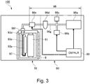
- FIG 3 is an illustration of a high-pressure air path of the image forming apparatus.
- the fixing device 9 in which the discharging unit 93 is mounted is disposed by being shifted toward a front (surface) side of the image forming apparatus 100.
- a high-pressure air path 96 by an air supplying mechanism for supplying the compressed air to the discharging unit 93 is disposed by being shifted toward a rear (surface) side of the image forming apparatus 100.
- a solenoid (electromagnetic) valve 96e functioning as a pressure limiting mechanism and a pressure adjusting valve 96c are provided.
- the compressor 96a generates high-pressure air blown by the air nozzle 93a.
- the air compressor 96a is provided in a casing of the image forming apparatus 100 and compresses ambient air and supplies the compressed air to the high-pressure air path 96.
- a joint part (component) 96j which is an example of a relay member relays an air tube 96g.
- a pressure-heating solenoid valve 96b which is also the pressure limiting mechanism discharges the high-pressure air, in the high-pressure air path 96, to the outside.
- the controller 99 actuates the pressure-heating solenoid valve 96b during actuation of the compressor 96a and lowers the pressure in the high-pressure air path 96 to atmospheric pressure, so that an actuating torque of the compressor 96a is decreased to a small value.
- An air filter 96d separates and discharges a drain, water, dirt and dust contained in the high-pressure air discharged by the air compressor 96a.
- the solenoid valve 93e switches supply and block of the high-pressure air supplied to the air nozzle 93a.
- the solenoid valve 93e is connected with a main assembly-side coupler 96f by the air tube 96g and sends the high-pressure air, in the high-pressure air path 96, to the air nozzle 93a.
- the air nozzle 93a which is an example of an air nozzle is capable of blowing the high-pressure air onto the fixing roller 91.
- the air nozzle 93a blows the high-pressure air onto the leading end of the recording material P and separates the recording material P from the fixing roller 91.
- the main assembly-side coupler 96f is detachably connected to a fixing-side coupler 93d. The high-pressure air supplied from the main assembly-side coupler 96f to the discharging unit 93 through the fixing-side coupler 93d is blown from the air nozzle 93a onto the fixing roller 91.
- the coupler 99 actuates the air compressor 96a and thereafter closes the pressure-heating solenoid valve 96b. Thereafter, compressed air with a pressure P2 adjusted by the pressure adjusting valve 96c is accumulated in the high-pressure air path 96 from the compressor 96s to the solenoid valve 96e.
- the pressure adjusting valve 96c regulates (adjusts) the pressure of the high-pressure air supplied to the air nozzle 93a to a first pressure P2.
- the pressure adjusting valve 96c discharges the high-pressure air, in the high-pressure air path 96, to the outside air at the pressure P2 when the pressure in the high-pressure air path 96 reaches the pressure P2, so that the pressure adjusting valve 96c maintains the pressure, in the high-pressure air path 96 ranging to the solenoid valve 96e, at the pressure P2.
- the solenoid valve 96e is adjusted so that the pressure P2 is about 0.3 MPa.
- the controller 99 actuates the solenoid valve 96e so that the recording material is separated from the fixing roller 91.
- the controller 99 turns on the solenoid valve 96e immediately before the leading end of the recording material reaches a blowing position on the fixing roller 91, and starts blowing of the high-pressure air, accumulated in the high-pressure air path 96 and having the pressure P2, onto the leading end of the recording material. Thereafter the supply of the high-pressure air by the compressor 96a cannot catch up with an amount of flow from the air nozzle 93a, so that blowing pressure of the high-pressure air in the high-pressure air path 96 drastically lowers.
- the controller 99 turns off the solenoid valve 96e at a portion of about 1/3 of a length of the recording material P with respect to the feeding direction and accumulates the high-pressure air with the pressure Ps in the high-pressure air path, and prepares for a leading end of a subsequent recording material P.
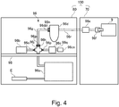
- Figure 4 is an illustration of an arrangement of the air tube.
- Figure 5 includes illustrations of an air tube mounting structure.
- a casing of a compressor unit 80 separable from a main assembly casing in which the fixing device 9 is mounted is provided in the image forming apparatus 100.
- the image forming apparatus 100 which is an example of a first casing accommodates the air nozzle 93a and the solenoid valve 96e.
- the compressor unit 80 which is an example of a second casing is detachably mountable to the image forming apparatus 100 and accommodates the compressor 96a and the pressure adjusting valve 96c.
- the casing of the compressor unit 80 is partitioned by a partition wall 98 into a space in the compressor 96a side and a space in the air filter 96d side.
- the joint part 96j for relaying piping of the high-pressure air path 96 is fixed.
- the joint part 96j is fixed to the partition wall 98 and relays the supply of the high-pressure air supplied from the compressor 96a.
- a cylindrical portion 96jp is a connected portion of the high-pressure air path 96 with the joint part 96j.
- the joint part 96j and the air filter 96d is connected by the air tube 96g.
- An end portion of the air tube 96g formed with a silicone rubber is fit on the cylindrical portion 96jp, formed of alumina, of the joint part 96j.
- the end portion of the air tube 96g is fixed to the joint part 96j by fastening (clamping) an outside (portion) of the air tube 96g with a tube clamp 96h.
- the tube clamp 96h is of a leaf spring type, and increases in inner diameter by pressing both end grips in an approaching direction and decreases in inner diameter by releasing the pressure application of the both end grips thereby to fasten the air tube 96g.
- the air tube 96g is fixed to the cylindrical portion 96jp of the joint part 96j in the following procedure.
- a connected portion between the air tube 96 and the air filter 96d is fixed using a similar constitution.
- An opposite end portion of the air tube 96g from the joint part 96j is fit on a cylindrical portion 96dp, formed of aluminum, of the air filter 96d, and the outside of the air tube 96g is fastened (clamped) by a tube clamp 96n.
- connection is made similarly using air tubes 960, 96p, 96q and 96r.
- the pressure in the high-pressure air path 96 is maintained at an operating pressure (first pressure) by the pressure adjusting valve 96c.
- the air tube 96g of the high-pressure air path 96 is not unclamped (and does not fall off) from the cylindrical portions 96jp and 96dp due to an internal pressure of the air tube 96g by which the fastening forces of the tube clamps 96h and 96n are overpowered.
- the pressure adjusting valve 96c causes clogging
- the pressure in the air tube 96g exceeds the pressure P2 and increases up to a maximum discharge pressure P1 of the compressor 96a.
- the tube clamps 96h and 96n cannot withstand the internal pressure of the air tube 96g.
- the air tube 96g floats from the cylindrical portions 96jp and 96dp by the pressure, so that there is a possibility that the air tube 96g is unclamped (and falls off) from one of the cylindrical portions 96jp and 96dp.
- connection is made similarly using the air tubes 96o, 96p, 96q and 96r, and therefore there is a possibility that also at any connected portion, the air tube is unclamped.
- a phenomenon that the air tube is unclamped by the internal pressure can generate at all of places of the high-pressure air path 96.
- the pressure at which one end portion of the air tube 96g connected with the joint part 96j is unclamped at the connected portion is intentionally made smaller by 20 % or more compared with the pressure at which all of other air tubes are unclamped at the connected portions.
- a plurality of connected portions (air tube clamped portions) in the high-pressure air path 96 includes at least one tube connected portion where the end portion of the air tube is fit on a tubular portion provided at a connected end of the connected portion and is externally fastened by a tube-like clamp which is an example of a fastening member. Further, when a discharge pressure of the compressor 96a is P1, the first pressure P2, and the pressure, in the high-pressure air path 96, at which the end portion of the air tube 96g is unclamped from the cylindrical portion 96jp at one tube connected portion is P3, P1 > P3 > P2 holds. All of the connected portions, in the high-pressure air path 96, other than the one tube connected portion are constituted so as to withstand static pressure larger than P3 by 20 % or more.
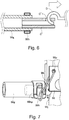
- Figure 6 is an illustration of an unclamping strength test of the air tube.
- the unclamping pressure of the connected portion in the joint part 96j side of the air tube 96g connecting the joint part 96j for relaying piping and the air filter 96d was set so as to be lower than that of the connected portion in the air filter 96d side by 20 % or more.
- the air tube 96g is prepared by cutting a tube material of about 15 mm in outer diameter, about 9 mm in inner diameter and formed of a silicone rubber, into a necessary length.
- the cylindrical portion 96jp, of the joint part 96, to which one end of the air tube 96g is connected, is formed to have a smooth peripheral surface free from unevenness and an outer diameter of about 8.5 mm.
- the cylindrical portion 96dp, of the air filter 96d, to which the other end of the air tube 96g is connected, is formed to have a smooth peripheral surface free from unevenness and an outer diameter of about 9.5 mm.
- the air tubes 96o, 96p, 96q and 96r provided between the devices other than between the joint part 96j and the air filter 96d were prepared by cutting the same materials as that of the air tube 96g into necessary lengths, respectively. Both end portions of each of the air tubes 96o, 96p, 96q and 96r are constituted similarly as the connected portions of the air tube 96g and the air filter 96d, and similar unclamping pressure is set, and the both end portions were connected to corresponding pneumatic elements.
- the clamps 96h and 96n of the leaf spring type are about 13 mm in inner diameter when the pressure application to the grip portions is released, and are about 16 mm in maximum inner diameter when the grip portions are pressed.
- the inner diameter of 9 mm of the air tube 96g exceeds the outer diameter of 8.5 mm of the cylindrical portion 96jp to be connected. However, by fastening the outer periphery of the air tube 96g with the tube clamp 96h, the high-pressure air is prevented from leaking out from a gap between the air tube 96g and the cylindrical portion 96jp.
- Insertion lengths of the air tube 96g into the cylindrical portion, 96jp and 96dp are each about 12 mm, and also widths of the tube clamps 96h and 96n with respect to an insertion direction are about 12 mm.
- a test cylindrical member C' is formed of the same material as the cylindrical portion 96jp which is a connection destination of the air tube 96g and is 8.5 mm in outer diameter which is the same as that of the cylindrical portion 96jp, and a through hole C'1 for locking a hook portion D of a digital force gage is formed.
- test cylindrical member C' An end portion of the test cylindrical member C' is inserted into the air tube 96g, and an end portion of the test cylindrical member C' in a side opposite from the air tube 96g is fixed by an unshown fixing means. Then, from a state in which the tube clamp 96h is mounted and a fastening force is exerted on the air tube 96g and the cylindrical member C', the hook portion D pulls the cylindrical member C' in an arrow direction via the digital force gage. A maximum load measured by the digital force gage in a process in which the tube clamp 96h is unclamped is regarded as the unclamping strength of the air tube 96g.
- Another test cylindrical member C' is formed of the same material as the cylindrical portion 96dp which is a connection destination of the air tube 96g and is 9.5 mm in outer diameter which is the same as that of the cylindrical portion 96dp. Also with regard to another test cylindrical member C', a similar test was conducted and the unclamping strength was obtained. Table 1 COD *1 DS *2 DSP *3 8.5 mm 76 - 89 N 0.8 MPa 9.5 mm 118 - 146 N 1.4 MPa *1: "COD" is the cylindrical portion outer diameter. *2: “DS” is the unclamping strength. *3: “DSP” is the unclamping static pressure.
- the unclamping strength of the air tube 96g was 67 - 89 N (6.7 - 8.9 kgf).
- the unclamping strength of the air tube 96g was 119 - 146 N (11.9 - 14.6 kgf).
- the unclamping strength somewhat varies also depending of difference among individuals of the air tube 96g, the cylindrical portion 96jp and the tube clamp 96h. However, as a result that a repetitive test of 10 times was conducted using the same material, a variation of the unclamping strength from an average of measured values was about 14 % at the maximum.
- the unclamping strength of one end portion of the air tube 96g is made smaller than the unclamping strength of the other end portion of the air tube 96g, and therefore, one end portion of the air tube 96g is unclamped early during the pressure rise in the high-pressure air path. Further, connection of the end portions of other air tubes is constituted in the same manner as that of the other end portion of the air tube 96g, and therefore, of the end portions of all of the air tubes, the other end portion of the air tube 96g is first unclamped.
- the connected portion of the one end portion of the air tube 96g intentionally weaken in unclamping strength is used as a mechanical fuse for releasing the high-pressure air before the pressure of the high-pressure air generated by the air compressor 96a reaches the maximum pressure P1.
- the connecting position of the one end portion of the air tube 96g is determined in advance, and therefore a maintenance property during a recovery operation by a service person becomes good.
- the end portion of the air tube for which the unclamping pressure is set at a small value is not limited to the connected portion with the joint part 96j.
- the end portion may also be any place such that the internal pressure in the high-pressure air path 96 exceeds the pressure P2 and a problem arises.
- protection requiring parts such as an electric substrate are provided in the neighborhood of the piping of the high-pressure air path 96
- a driver substrate E of the air compressor 96a exists in the neighborhood of the high-pressure air path 96.
- the air tube 96g is mounted to the joint part 96j partitioned from the driver substrate E by the partition wall (partition) 98. By doing so, even in the case where a band member 96i is broken, the driver substrate E can be protected from the leaping-off of the tube clamp 96h.
- Figure 7 is an illustration of a retaining member for the tube clamp.
- FIG 3 shows that during pressure rise of the high-pressure air in the high-pressure air path, in the case where the air tube 96g is unclamped vigorously from the cylindrical portion 96jp, there is a possibility that the tube clamp 96h leaps off with the vigor. At this time, there is a possibility that the tube clamp 96h which leaped off runs against a peripheral part and is broken or gets mixed in between devices on a circuit substrate and thus cannot be found.
- the band member 96i which is a flexible retaining member is connected to the tube clamp 96h.
- the band member 96i has a length in which the unclamping of the air tube 96g at the cylindrical portion 96jp cannot be prevented, and a free end thereof is retained by the tube clamp 96h.
- the band member 96i connects a through hole 96hp provided in the tube clamp 96h and a through hole 98h of the partition wall 98 fixed to a destination joint part 96j for the air tube 96g.
- the unclamping pressure fluctuates due to a pressure difference, a temperature difference, the presence or absence of vibration for each of the tube connected portions, differences in direction of the air tube and tensile direction, and the like.
- the difference of 20 % or more evaluated in the pulling-off test shown in Figure 6 is provided between one tube connected portion and all of other tube connected portions.
- the one tube connected portion is unclamped prior to other tube connected portions by artificially increasing the pressure in a normal temperature (20°C) environment by providing the difference of 20 % or more evaluated in the pulling-off test shown in Figure 6 .
- the plurality of connected portions in the high-pressure air path 96 includes two or more tube connected portions excluding the one tube connected portion.
- the tube connected portion can be evaluated.
- the smallest unclamping force of those of two or more tube connected portions is 20 % or more larger than the unclamping force of the one tube connected portion designed so as to be unclamped.
- Embodiment 1 a relationship of P1 > P3 > P2 is set among the pressure P2 adjusted by the pressure adjusting valve 96c, the unclamping pressure P3 at the predetermined one end portion and the maximum discharge pressure P1. For this reason, at the time when the pressure adjusting valve 96c clogs and the internal pressure of the high-pressure air path 96 exceeds P2 and reaches P3, the predetermined one end portion is unclamped to discharge the high-pressure air to the outside, so that further pressure rise can be avoided.
- the unclamping pressure is set at a value smaller than those at any of other end portions by 20 % or more. For this reason, when the pressure in the high-pressure air path 96 increases, the predetermined one end portion is unclamped prior to other end portions with reliability. For this reason, the unclamping air tube end portion is identified from the beginning and finding of the unclamped portion by the service person becomes early, and cause analysis is easy, so that a maintenance property during a recovery operation is satisfactorily maintained. In the fixing device in which the separation of the recording material is assisted using the compressed air, it becomes possible to improve the maintenance property during restoration of the device.
- one connected portion low in pressure resistance is unclamped prior to other connected portions, so that at many connected portions other than the one end portion low in pressure resistance, any of trace, change and lowering in pressure resistance are not caused. For this reason, also during the pressure rise after the unclamping of the air tube 96g is recovered, the air tube is unclamped at the cylindrical portion 96jp prior to other connected portions.
- the cylindrical portion 96jp is smaller in diameter than other tubular portions in the high-pressure air path 96. For this reason, a decrease in unclamping force at the cylindrical portion 96jp can be realized using the same air tube and the same tube clamp 96h.
- the air tube is a silicone rubber tube, and therefore, even when the air tube is used for a long term, the air tube is unclamped with high reproducibility to the pressure without sticking to the cylindrical portion 96jp. Further, the material is soft, and therefore, the unclamping force is easily controlled by a magnitude of the clamping force of the tube clamp.
- the partition wall 98 partitions the inside of the compressor unit into the space where the compressor 96a is disposed and the space where the cylindrical portion 96jp is disposed. For this reason, the tube clamp 96h and the air tube 96g which are unclamped from the cylindrical portion 96jp cannot enter the space where the compressor 96a is disposed.
- FIG 8 is an illustration of an air tube connected portion in Embodiment 2.
- Embodiment 2 is constituted similarly as Embodiment 1 except that the cylindrical portion 96dp in which the air tube 96g is inserted is provided with a constriction.
- constitutions in common with Embodiment 1 are represented by common symbols and will be omitted from redundant description.
- Embodiment 1 all of the tubular portions which are destinations of the air tube connected portions have a straight cylindrical shape, and at a preliminarily selected one tube connected portion, the diameter of the tubular portion was made smaller than those of other tube connected portions, so that the difference in unclamping pressure was set.
- the tubular portion has the straight cylindrical shape at the preliminarily selected one tube connected portion, and at all of other tube connected portions, an outer appearance of the destination tubular portion had a so-called volute (bamboo shoot) type having a ring-shaped unevenness. That is, at the destination tubular portion, a stepped portion functioning as a retainer for the air tube 96g was provided.
- the cylindrical portion 96jp is straight in shape, and other tubular portions are provided with the ring-shaped unevenness. For this reason, a decrease in unclamping force at the cylindrical portion 96jp can be realized using the same air tube and the same clamp 96h.
- a difference in unclamping force was set by a magnitude of a fastening force of the tube clamp.
- an inner diameter dimension of the clamp 96h was made larger than those of other tube connected portions, so that the fastening force for the air tube 96g was made small and thus the unclamping strength was adjusted.
- the tube clamp 96h used at the cylindrical portion 96jp is smaller in fastening force than the tube clamps used at other the ring-shaped portions. For this reason, a decrease in unclamping force at the cylindrical portion 96jp can be realized using the same tubular portion and the same air tube.
- FIG 9 is an illustration of a high-pressure air path in Embodiment 4.
- the unclamping force of the air tube 96g is decreased only at the connected portion between the joint part 96j and the air tube 96g, and the connected portion was used as the mechanical fuse.
- the pressure-heating solenoid valve 96b was used as the mechanical fuse for releasing the compressed air.
- the pressure-heating solenoid valve 96b discharges the high-pressure air, in the high-pressure air path 96, to the outside.
- the controller 99 actuates the pressure-heating solenoid valve 96b during actuation of the compressor 96a and lowers the pressure in the high-pressure air path 96 to atmospheric pressure, so that an actuating torque of the compressor 96a is decreased to a small value.
- the pressure-heating solenoid valve 96b is mechanically actuated when the pressure in the high-pressure air path 96 reaches the allowable pressure (second pressure P4), and lowers the pressure in the high-pressure air path to the atmospheric pressure. With no electrical signal, the pressure-heating solenoid valve 96b is actuated only by reacting with the pressure of the high-pressure air in the joint part 96j.
- the pressure-heating solenoid valve 96b which is an example of the pressure releasing valve is connected with the high-pressure air path 96 and communicates with the ambient air when the pressure in the high-pressure air path 96 reaches the second pressure P4, and thus regulates the pressure in the high-pressure air path 96.
- the pressure-heating solenoid valve 96b (SMC Corporation, VX-240 DA) is a solenoid valve of a type in which the solenoid valve is closed during energization and is open during non-energization, and releases the compressed air remaining inside the piping after the compressor 96a is at rest.
- the pressure-heating solenoid valve 96b When a pressure difference between a primary side and a secondary side of the valve exceeds a maximum operating pressure difference, the pressure-heating solenoid valve 96b is forcedly placed in a valve open state.
- a pressure-heating solenoid valve 96b of 0.4 - 0.5 MPa in maximum operating pressure difference can be used as the pressure-heating solenoid valve 96b.
- the pressure-heating solenoid valve 96b opens, so that the compressed air is released.
- the pressure value of 0.4 - 0.5 MPa at this time is made smaller than a pressure value at which the clamp 96h is unclamped at the tube connected portion lowest in unclamping strength. For this reason, when the inner pressure of the piping increases, first, a safety mechanism of the pressure-heating solenoid valve 96b acts first, so that the compressed air is released. By this, when the second pressure is P4, P1 > P3 > P4 > P2 holds. Accordingly, a possibility that the state of the clamp 96h reaches a leaping-off state can be further lowered, so that the safety can be further enhanced.
- the compressor unit 80 was provided independently of the main assembly casing of the image forming apparatus 100 in which the fixing device 9 was mounted.
- the compressor 96a and the high-pressure air path 96 which are accommodated in the compressor unit 80 may also be provided in the main assembly casing of the image forming apparatus 100 in which the fixing device 9 is mounted.
- the compressor 96a and the high-pressure air path 96 may also be accommodated by providing a casing of the fixing device independent of the main assembly casing of the image forming apparatus 100.
- Embodiment 1 of the pair of rotatable members for forming the nip for carrying out the fixing process, one used the roller member and the other used the endless belt, but a combination of the pair of rotatable members is not limited to the combination of the roller member and the endless belt.
- the combination of the pair of rotatable members may also be combinations of the heating roller and the pressing roller, the heating belt and the pressing roller, and the heating belt and the pressing belt.
- the air tubes are not required that all of the air tubes are flexible, that all of the air tubes are silicone rubber tubes and that all of the air tubes have the same diameter and the same thickness.
- the air tubes may only be required that at least one air tube is lower in unclamping pressure at one end than at the other end, and may only be required that the pressure resistance at the other connected portion in the high-pressure air path 96 is higher than the unclamping pressure at one end.
- the image heating apparatus in which a time required for the recovery operation is shortened.
Landscapes
- Physics & Mathematics (AREA)
- General Physics & Mathematics (AREA)
- Life Sciences & Earth Sciences (AREA)
- Engineering & Computer Science (AREA)
- Atmospheric Sciences (AREA)
- Biodiversity & Conservation Biology (AREA)
- Ecology (AREA)
- Environmental & Geological Engineering (AREA)
- Environmental Sciences (AREA)
- Fixing For Electrophotography (AREA)
- Joints That Cut Off Fluids, And Hose Joints (AREA)
Abstract
Description
- The present invention relates to an image heating apparatus for heating a toner image on a sheet.
- An image forming apparatus in which the toner image is formed on a recording material (sheet) and the recording material on which the toner image is formed is heated and pressed by a fixing device (image heating apparatus) and an image is fixed on the recording material has been widely used. In such a fixing device, at a nip formed by a pair of rotatable members, a fixing process is carried out.
- In the case where the recording material is thin and low in rigidity, the recording material is not readily separated from the rotatable members. For this reason, a proposed that an air nozzle is provided in the neighborhood of the rotatable members and the recording material is forcedly separated from the rotatable members by blowing air, supplied from a compressor, from the air nozzle onto the recording material has been made (Japanese Laid-Open Patent Application
SHO 60-247672 2007-94327 - In an air supplying path from the compressor to the air nozzle, many air tubes are provided for being connected between devices. These air tubes are fixed by clamps in a state in which the air tubes are inserted into the devices, and during operation, are constituted so as not be unclamped when the air tubes are in a normal condition.
- On the other hand, in the case where a pressure in the air supplying path is excessively increased by out-of-order of the device, there is a liability that the air tube is unclamped against a clamp fastening force.
- In such a case, a recovery operation is to be carried out, but when all of the portions where many air tubes are connected are checked thoroughly, the recovery operation requires a long time.
- According to an aspect of the present invention, there is provided an image heating apparatus comprising: first and second rotatable members for forming a nip for heating a toner image on a sheet; a compressor; an air nozzle for blowing air, generated by the compressor, on the first rotatable member; and a supplying mechanism for supplying air from the compressor to the air nozzle, the supplying mechanism including a plurality of air tubes and a plurality of clamps for fixing the plurality of air tubes, wherein a pressure at which the air tube is unclamped is lower only at a predetermined portion of the clamped portions than the other portions by 20% or more.
-
-
Figure 1 is an illustration of a structure of an image forming apparatus. -
Figure 2 is an illustration of a structure of a fixing device. -
Figure 3 is an illustration of a high-pressure air path of the image forming apparatus. -
Figure 4 is an illustration of an arrangement of air tubes. -
Figure 5 includes illustrations of an air tube mounting structure. -
Figure 6 is an illustration of an unclamping strength test of the air tube. -
Figure 7 is an illustration of a retaining member for a tube clamp. -
Figure 8 is an illustration of a connected portion of an air tube in Embodiment 2. -
Figure 9 is an illustration of a high-pressure air path in Embodiment 4. - In the following, with reference to the drawings, an embodiment of the present invention will be described specifically.
-
Figure 1 is an illustration of a structure of an image forming apparatus. As shown inFigure 1 , animage forming apparatus 100 is a tandem-type full-color printer of an intermediary transfer type in which image forming apparatus Pa, Pb, Pc, Pd of yellow, magenta, cyan, black are arranged along anintermediary transfer belt 20. - At the image forming portion Pa, a yellow toner image is formed on a
photosensitive drum 3a and is primary-transferred onto theintermediary transfer belt 20. At the image forming portion Pb, a magenta toner image is formed on aphotosensitive drum 3b and is primary-transferred onto theintermediary transfer belt 20. At the image forming portion Pc and Pd, a cyan toner image and a black toner image on thephotosensitive drums 3c and 3d, respectively, and are primary-transferred onto theintermediary transfer belt 20. - A recording material (sheet) P is taken out one by one from a
cassette 10 and is on stand-by at aregistration roller 12. The recording material P is fed by theregistration roller 12 to a secondary transfer portion T2 in timing with the toner images on theintermediary transfer belt 20, and the toner images are secondary-transferred onto the recording material P. The recording material P on which the toner images of the four colors are secondary-transferred is fed to afixing device 9 and is heated and pressed by thefixing device 9, so that an image is fixed on a surface of the recording material P, and thereafter is discharged on atray 13 outside the apparatus. - In double-side printing, the recording material on which the images are fixed at a front surface thereof by the
fixing device 9 is sent into a reverse feeding path and is switched back, and then passes transfer afeeding path 113 in a state in which a leading end and a trailing end are reversed and in which the front surface and a back surface are reversed, and is on stand-by at theregistration roller 12. Then, the recording material is fed again to the secondary transfer portion T2, where the toner images are transferred onto the back surface of the recording material and are fixed on the back surface of the recording material by thefixing device 9, and thereafter, the recording material is discharged on thetray 13 at an outer portion of the apparatus (printer). - The image forming portions Pa, Pb, Pc, Pd have substantially the same constitution except that the colors of the toners used in developing
devices - At the image forming portion Pa, at a periphery of the
photosensitive drum 3a, a corona charger 2a, anexposure device 5a, the developingdevice 1a, atransfer roller 6a and adrum cleaning device 4a are provided. - The corona charger 2a electrically charges a surface of the
photosensitive drum 3a to a uniform potential. Theexposure device 5a writes the electrostatic image for the image on thephotosensitive drum 3a by scanning the photosensitive drum surface with a laser beam. The developingdevice 1a develops the electrostatic image into the toner image on thephotosensitive drum 3a by transferring the toner on the electrostatic image on thephotosensitive drum 3a. Thetransfer roller 6a primary-transfers the toner image from thephotosensitive drum 3a onto theintermediary transfer belt 20 under application of a voltage of an opposite polarity to a charge polarity of the toner. - The
intermediary transfer belt 20 is extended around and supported by atension roller 14, adriving roller 15 and anopposing roller 16, and is driven by thedriving roller 15, so that theintermediary transfer belt 20 rotates in an arrow direction. Asecondary transfer roller 11 press-contacts theintermediary transfer belt 20 supported by theopposing roller 16 and forms the secondary transfer portion T2. Abelt cleaning device 30 rubs theintermediary transfer belt 20 with a cleaning web and thus removes a transfer residual toner passed transfer the secondary transfer portion T2. -
Figure 2 is an illustration of a structure of the fixing device functioning as an image heating apparatus. As shown inFigure 2 , the recording material P on which the toner image is transferred is fed by apressing belt 92a and is introduced into a fixing nip N, and is nipped and fed by afixing roller 91 and apressing unit 92. The toner image on the recording material P is heated and pressed in a process of passing through the fixing nip N, so that the toner image is fixed on the surface of the recording material. Thefixing device 9 causes thepressing belt unit 92 to press-contact thefixing roller 91, so that the fixing nip is formed between thefixing roller 91 and thepressing belt unit 92. Thefixing roller 91 and thepressing belt unit 92 which are an example of pair of rotatable members heat, the recording material on which the toner image is carried. - The
fixing roller 91 includes acore metal 91a formed of a cylindrical metal, a heat-resistantelastic layer 91b disposed in an outer side of thecore metal 91a, and aparting layer 91c of a heat-resistant fluorine-containing resin material coated on an outer peripheral surface of theelastic layer 91b in order to improve a toner parting property. Thecore metal 91a is an aluminum-mode cylindrical material of 77 mm in outer diameter, 6 mm in thickness and 350 mm in length. Theelastic layer 91b is a 1.5 mm-thick silicone rubber of 20 degrees in JIS-A hardness. Theparting layer 91c is a 50 µm-thick PFA tube. - The
fixing roller 91 is rotatably supported at both end portions by afixing device frame 94, and is rotationally driven at a predetermined speed (e.g., 500 mm/s in peripheral speed) in an arrow A direction by an unshown driving source. - Inside the
core metal 91a, ahalogen heater 102 of 1200 W in (normal) related electric power and heats thefixing roller 91 from the inside of thefixing roller 91. Electric power supply of thehalogen heater 102 is controlled by an unshown temperature control circuit so that a surface temperature of thefixing roller 91 measured by an unshown thermistor maintains a target temperature for temperature adjustment. - The
pressing belt 92a is an endless belt of ϕ70 mm in outer diameter such that a 200 µm-thick elastic layer of a silicone rubber is disposed on a 100 µm-thick base layer formed of polyimide. - The
pressing belt 92a is stretched by an entrance roller (driving roller) 92b, aseparation roller 92c, asteering roller 92d and aphotosensitive drum pad 92e. Thepressing belt 92a is rotationally driven by a driving force inputted from an unshown driving source into theseparation roller 92c. - The
separation roller 92c presses thepressing belt 92a toward thefixing roller 91 by being urged at both end portions by an unshown pressing mechanism (spring). Thepressing pad 92e carries out pressing of 490 N (50 kgf) in total. - The
pressing pad 92e presses thepressing belt 92a toward the fixingroller 91 by being urged at both end portions by an unshown pressing mechanism (spring). Theseparation roller 92c carries out pressing of 490 N (50 kgf) in total. - The fixing
device 9 nips and feeds the recording material, on which the toner image is carried, by the fixingroller 91 and thepressing belt 92a, so that the image is formed on the recording material P. In thefixing device 9, an unfixed toner image formed on the recording material P directly contacts the surface of the fixingroller 91, and therefore there is a possibility that the recording material P sticks to the fixingroller 91 due to viscosity of melted toner and is moved without being peeled off from the fixingroller 91. By this, there is a possibility that a jam of the recording material is caused. - The fixing
device 9 peels off the recording material P sticking to thepressing belt 92a by causing aseparation claw 88, formed of a heat-resistant resin material, to contact and rub the surface of thepressing belt 92a. On theseparation claw 88, there is a need to exert a small pressing force in order to be closely contacted to thepressing belt 92a. - However, in the case where the small pressing force is exerted on the
separation claw 88 by causing theseparation claw 88 to contact the fixingroller 91, a peripheral surface of the fixingroller 91 sliding with a free end of theseparation claw 88 is locally abraded. When a hard foreign matter is deposited on theseparation claw 88, there is a possibility that the surface layer of the fixingroller 91 is damaged. - Further, in the case of the recording material such as thin paper small in weight per unit area, there is a possibility that a leading end portion of the recording material runs against the
separation claw 88 and is damaged, and generates creases, folds or breakage. In order to solve such problems, in Embodiment 1, compressed air is blown onto the leading end of the recording material P on the fixingroller 91, so that the recording material P is peeled off. - A discharging
unit 92 is disposed downstream of the fixing nip N with respect to a recording material feeding direction. The discharging unit 93 separates the recording material P, passed through the fixing nip N, from the fixingroller 91 by high-pressure air blast by anair nozzle 93a, and discharges the recording material P to an outside of the fixingdevice 9 by a feedingroller pair 93c. - The
air nozzle 93a blows high-pressure air onto the leading end of the recording material P, on the fixingroller 91, after passing through the fixing nip N, and peels off the recording material P from the fixingroller 91. The feedingroller pair 93c nips and feeds the peeled recording material P and discharges the recording material P to the outside of the fixingdevice 9. - The discharging unit 93 is rotatable about a
rotation center 94a of the fixingdevice frame 94. The discharging unit 93 is rotatable between a disposing position where the discharging unit 93 is disposed when the fixingdevice 9 performs a fixing operation and a retracted position where the discharging unit 93 is rotated and retracted from the fixingroller 91 when the recording material P remaining in thefixing device 9 is removed during jam clearance. The discharging unit 93 is rotated and raised to the retracted position, whereby a space ensuring an unobstructed view from a downstream side is formed in the downstream side of the fixing nip N, so that the recording material P which has not been discharged can be discharged. - The
air nozzle 93a is supported by the discharging unit 93 rotatably about a nozzle rotation center 93h, and is pressed by a movable end β of a helical torsion coil spring with a fixed end α. To the fixingdevice frame 94, anozzle positioning pin 94b is fixed. When the discharging unit 93 disposed in thefixing device 9, an abutting surface 93g of theair nozzle 93a abuts against thenozzle positioning pin 94b, so that theair nozzle 93a is positioned relative to the fixingroller 91. - In the case where a weight per unit area of the recording material P is 128 g/m2 or less, a
controller 99 discriminates that peeling by compressed air is needed. When the recording material P is sent into the fixingdevice 9, a recordingmaterial detecting sensor 95 detects the leading end of the recording material P. Thecontroller 99 causes theair nozzle 93a to blow the compressed air onto the leading end of the recording material P on the fixingroller 91 at a speed of about 300 m/sec after a lapse of a predetermined time on the basis of timing when the recordingmaterial detecting sensor 95 detected the leading end of the recording material P, and peels off the recording material P from the fixingroller 91. -
Figure 3 is an illustration of a high-pressure air path of the image forming apparatus. As shown inFigure 3 , the fixingdevice 9 in which the discharging unit 93 is mounted is disposed by being shifted toward a front (surface) side of theimage forming apparatus 100. A high-pressure air path 96 by an air supplying mechanism for supplying the compressed air to the discharging unit 93 is disposed by being shifted toward a rear (surface) side of theimage forming apparatus 100. - As shown in
Figure 3 , in the high-pressure air path 96 by the air supplying mechanism for supplying the air from acompressor 96a to theair nozzle 93a, at least a solenoid (electromagnetic)valve 96e functioning as a pressure limiting mechanism and apressure adjusting valve 96c are provided. Thecompressor 96a generates high-pressure air blown by theair nozzle 93a. Theair compressor 96a is provided in a casing of theimage forming apparatus 100 and compresses ambient air and supplies the compressed air to the high-pressure air path 96. As shown inFigure 4 , a joint part (component) 96j which is an example of a relay member relays anair tube 96g. - A pressure-
heating solenoid valve 96b which is also the pressure limiting mechanism discharges the high-pressure air, in the high-pressure air path 96, to the outside. Thecontroller 99 actuates the pressure-heating solenoid valve 96b during actuation of thecompressor 96a and lowers the pressure in the high-pressure air path 96 to atmospheric pressure, so that an actuating torque of thecompressor 96a is decreased to a small value. Anair filter 96d separates and discharges a drain, water, dirt and dust contained in the high-pressure air discharged by theair compressor 96a. - The
solenoid valve 93e switches supply and block of the high-pressure air supplied to theair nozzle 93a. Thesolenoid valve 93e is connected with a main assembly-side coupler 96f by theair tube 96g and sends the high-pressure air, in the high-pressure air path 96, to theair nozzle 93a. Theair nozzle 93a which is an example of an air nozzle is capable of blowing the high-pressure air onto the fixingroller 91. Theair nozzle 93a blows the high-pressure air onto the leading end of the recording material P and separates the recording material P from the fixingroller 91. The main assembly-side coupler 96f is detachably connected to a fixing-side coupler 93d. The high-pressure air supplied from the main assembly-side coupler 96f to the discharging unit 93 through the fixing-side coupler 93d is blown from theair nozzle 93a onto the fixingroller 91. - The
coupler 99 actuates theair compressor 96a and thereafter closes the pressure-heating solenoid valve 96b. Thereafter, compressed air with a pressure P2 adjusted by thepressure adjusting valve 96c is accumulated in the high-pressure air path 96 from the compressor 96s to thesolenoid valve 96e. - The
pressure adjusting valve 96c regulates (adjusts) the pressure of the high-pressure air supplied to theair nozzle 93a to a first pressure P2. Thepressure adjusting valve 96c discharges the high-pressure air, in the high-pressure air path 96, to the outside air at the pressure P2 when the pressure in the high-pressure air path 96 reaches the pressure P2, so that thepressure adjusting valve 96c maintains the pressure, in the high-pressure air path 96 ranging to thesolenoid valve 96e, at the pressure P2. Thesolenoid valve 96e is adjusted so that the pressure P2 is about 0.3 MPa. - The
controller 99 actuates thesolenoid valve 96e so that the recording material is separated from the fixingroller 91. Thecontroller 99 turns on thesolenoid valve 96e immediately before the leading end of the recording material reaches a blowing position on the fixingroller 91, and starts blowing of the high-pressure air, accumulated in the high-pressure air path 96 and having the pressure P2, onto the leading end of the recording material. Thereafter the supply of the high-pressure air by thecompressor 96a cannot catch up with an amount of flow from theair nozzle 93a, so that blowing pressure of the high-pressure air in the high-pressure air path 96 drastically lowers. Thecontroller 99 turns off thesolenoid valve 96e at a portion of about 1/3 of a length of the recording material P with respect to the feeding direction and accumulates the high-pressure air with the pressure Ps in the high-pressure air path, and prepares for a leading end of a subsequent recording material P. -
Figure 4 is an illustration of an arrangement of the air tube.Figure 5 includes illustrations of an air tube mounting structure. As shown inFigure 4 , in theimage forming apparatus 100, a casing of acompressor unit 80 separable from a main assembly casing in which thefixing device 9 is mounted is provided. Theimage forming apparatus 100 which is an example of a first casing accommodates theair nozzle 93a and thesolenoid valve 96e. Thecompressor unit 80 which is an example of a second casing is detachably mountable to theimage forming apparatus 100 and accommodates thecompressor 96a and thepressure adjusting valve 96c. The casing of thecompressor unit 80 is partitioned by apartition wall 98 into a space in thecompressor 96a side and a space in theair filter 96d side. - To the
partition wall 98, thejoint part 96j for relaying piping of the high-pressure air path 96 is fixed. Thejoint part 96j is fixed to thepartition wall 98 and relays the supply of the high-pressure air supplied from thecompressor 96a. A cylindrical portion 96jp is a connected portion of the high-pressure air path 96 with thejoint part 96j. Thejoint part 96j and theair filter 96d is connected by theair tube 96g. An end portion of theair tube 96g formed with a silicone rubber is fit on the cylindrical portion 96jp, formed of alumina, of thejoint part 96j. The end portion of theair tube 96g is fixed to thejoint part 96j by fastening (clamping) an outside (portion) of theair tube 96g with atube clamp 96h. Thetube clamp 96h is of a leaf spring type, and increases in inner diameter by pressing both end grips in an approaching direction and decreases in inner diameter by releasing the pressure application of the both end grips thereby to fasten theair tube 96g. - As shown in
Figure 5 , theair tube 96g is fixed to the cylindrical portion 96jp of thejoint part 96j in the following procedure. - (1) An operator fits the
tube clamp 96h on theair tube 96g at a position somewhat remote from the end portion of theair tube 96g is advance. Thetube clamp 96h is of the leaf spring type, and when the grip portions of thetube clamp 96h are caught using a tool such as a long-nose plier, the inner diameter of thetube clamp 96h is enlarged, so that thetube clamp 96h is slidable in an axial direction. - (2) The operator fits the
air tube 96g on the cylindrical portion 96jp and pushes theair tube 96g to a predetermined position. - (3) The operator slides the
tube clamp 96h along theair tube 96g in a state in which the inner diameter of thetube clamp 96h is enlarged, and positions thetube clamp 96h at an engaging portion with the cylindrical portion 97jp. - (4) The operator releases the pressure application to the grip portions of the
tube clamp 96h. By this, the inner diameter of thetube clamp 96h decreases, and a fastening force acts on theair tube 96g, so that theair tube 96g is fixed to the cylindrical portion 96jp. - As shown in
Figure 4 , also a connected portion between theair tube 96 and theair filter 96d is fixed using a similar constitution. An opposite end portion of theair tube 96g from thejoint part 96j is fit on a cylindrical portion 96dp, formed of aluminum, of theair filter 96d, and the outside of theair tube 96g is fastened (clamped) by atube clamp 96n. - As shown in
Figure 4 , in the high-pressure air path 96, also between pneumatic (air pressure) elements other than between thejoint part 96j and theair filter 96d, connection is made similarly usingair tubes - As shown in
Figure 3 , in the case where the high-pressure air for separating the recording material P from the fixingroller 91 is generated by theair compressor 96a, the pressure in the high-pressure air path 96 is maintained at an operating pressure (first pressure) by thepressure adjusting valve 96c. For this reason, theair tube 96g of the high-pressure air path 96 is not unclamped (and does not fall off) from the cylindrical portions 96jp and 96dp due to an internal pressure of theair tube 96g by which the fastening forces of the tube clamps 96h and 96n are overpowered. - However, in the case where the
pressure adjusting valve 96c causes clogging, there is a possibility that the pressure in theair tube 96g exceeds the pressure P2 and increases up to a maximum discharge pressure P1 of thecompressor 96a. When the internal pressure of theair tube 96g increases, the tube clamps 96h and 96n cannot withstand the internal pressure of theair tube 96g. Theair tube 96g floats from the cylindrical portions 96jp and 96dp by the pressure, so that there is a possibility that theair tube 96g is unclamped (and falls off) from one of the cylindrical portions 96jp and 96dp. - Further, in the high-
pressure air path 96, also between devices other than between thejoint part 96j and theair filter 96d, connection is made similarly using theair tubes pressure air path 96. - When the air tube is unclamped by the internal pressure, in order to check that which end portion of which air tube in the high-pressure air path is unclamped, it is required that all of the connected portions of the high-
pressure air path 96 are checked thoroughly. When all of the connected portions of the high-pressure air path 96 are checked thoroughly, it takes time to identify the cause, so that a device recovery maintenance property by a service person becomes poor. - Therefore, in this embodiment, the pressure at which one end portion of the
air tube 96g connected with thejoint part 96j is unclamped at the connected portion is intentionally made smaller by 20 % or more compared with the pressure at which all of other air tubes are unclamped at the connected portions. By this, when thepressure adjusting valve 96c clogs and the pressure in the high-pressure air path 96 increases, the air tube is unclamped only at one connected portion low in unclamping pressure, so that the pressure in the high-pressure air path 96 is released, and therefore, further pressure increase of the high-pressure air path 96 is prevented. - A plurality of connected portions (air tube clamped portions) in the high-
pressure air path 96 includes at least one tube connected portion where the end portion of the air tube is fit on a tubular portion provided at a connected end of the connected portion and is externally fastened by a tube-like clamp which is an example of a fastening member. Further, when a discharge pressure of thecompressor 96a is P1, the first pressure P2, and the pressure, in the high-pressure air path 96, at which the end portion of theair tube 96g is unclamped from the cylindrical portion 96jp at one tube connected portion is P3, P1 > P3 > P2 holds. All of the connected portions, in the high-pressure air path 96, other than the one tube connected portion are constituted so as to withstand static pressure larger than P3 by 20 % or more. -
Figure 6 is an illustration of an unclamping strength test of the air tube. In Embodiment 1, the unclamping pressure of the connected portion in thejoint part 96j side of theair tube 96g connecting thejoint part 96j for relaying piping and theair filter 96d was set so as to be lower than that of the connected portion in theair filter 96d side by 20 % or more. - The
air tube 96g is prepared by cutting a tube material of about 15 mm in outer diameter, about 9 mm in inner diameter and formed of a silicone rubber, into a necessary length. The cylindrical portion 96jp, of thejoint part 96, to which one end of theair tube 96g is connected, is formed to have a smooth peripheral surface free from unevenness and an outer diameter of about 8.5 mm. The cylindrical portion 96dp, of theair filter 96d, to which the other end of theair tube 96g is connected, is formed to have a smooth peripheral surface free from unevenness and an outer diameter of about 9.5 mm. - As shown in
Figure 4 , theair tubes joint part 96j and theair filter 96d were prepared by cutting the same materials as that of theair tube 96g into necessary lengths, respectively. Both end portions of each of theair tubes air tube 96g and theair filter 96d, and similar unclamping pressure is set, and the both end portions were connected to corresponding pneumatic elements. - The
clamps - The inner diameter of 9 mm of the
air tube 96g exceeds the outer diameter of 8.5 mm of the cylindrical portion 96jp to be connected. However, by fastening the outer periphery of theair tube 96g with thetube clamp 96h, the high-pressure air is prevented from leaking out from a gap between theair tube 96g and the cylindrical portion 96jp. - Insertion lengths of the
air tube 96g into the cylindrical portion, 96jp and 96dp are each about 12 mm, and also widths of the tube clamps 96h and 96n with respect to an insertion direction are about 12 mm. - As shown in
Figure 6 , a sample which reproduces a connection state of theair tube 96g at both end portions was prepared, and the unclamping strength was compared by a tensile test. - A test cylindrical member C' is formed of the same material as the cylindrical portion 96jp which is a connection destination of the
air tube 96g and is 8.5 mm in outer diameter which is the same as that of the cylindrical portion 96jp, and a through hole C'1 for locking a hook portion D of a digital force gage is formed. - An end portion of the test cylindrical member C' is inserted into the
air tube 96g, and an end portion of the test cylindrical member C' in a side opposite from theair tube 96g is fixed by an unshown fixing means. Then, from a state in which thetube clamp 96h is mounted and a fastening force is exerted on theair tube 96g and the cylindrical member C', the hook portion D pulls the cylindrical member C' in an arrow direction via the digital force gage. A maximum load measured by the digital force gage in a process in which thetube clamp 96h is unclamped is regarded as the unclamping strength of theair tube 96g. - Another test cylindrical member C' is formed of the same material as the cylindrical portion 96dp which is a connection destination of the
air tube 96g and is 9.5 mm in outer diameter which is the same as that of the cylindrical portion 96dp. Also with regard to another test cylindrical member C', a similar test was conducted and the unclamping strength was obtained.Table 1 COD*1 DS*2 DSP*3 8.5 mm 76 - 89 N 0.8 MPa 9.5 mm 118 - 146 N 1.4 MPa *1: "COD" is the cylindrical portion outer diameter.
*2: "DS" is the unclamping strength.
*3: "DSP" is the unclamping static pressure. - As shown in Table 1, in the case where the outer diameter of the cylindrical portion 96jp is 9.5 mm, the unclamping strength of the
air tube 96g was 67 - 89 N (6.7 - 8.9 kgf). On the other hand, in the case where the cylindrical portion 96dp is 9.5 mm, the unclamping strength of theair tube 96g was 119 - 146 N (11.9 - 14.6 kgf). - The unclamping strength somewhat varies also depending of difference among individuals of the
air tube 96g, the cylindrical portion 96jp and thetube clamp 96h. However, as a result that a repetitive test of 10 times was conducted using the same material, a variation of the unclamping strength from an average of measured values was about 14 % at the maximum. - In the case where this result is applied to Embodiment 1, when the unclamping strength at the cylindrical portion 96jp of 8.5 mm in outer diameter is converted into a piping internal pressure, the internal pressure is about 0.57 - 0.63 MPa. Accordingly, even when the
pressure adjusting valve 96c clogs and the pressure of the high-pressure air in the high-pressure air path 96 becomes high, one end portion of theair tube 96g is unclamped at the pressure P3 = 0.57 - 0.63 MPa lower than the maximum discharge pressure P1 = 1.5 MPa of the compressor. The high-pressure air is discharged to the outside air from the cylindrical portion 96jp from which one end portion of theair tube 96g is unclamped, so that further pressure rise in the high-pressure air path 96 is avoided. - Further, the unclamping strength of 67 - 89 N at the cylindrical portion 96jp of 8.5 mm in outer diameter and the unclamping strength of 119 - 146 N at the cylindrical portion 96dp of 9.5 mm in outer diameter provide a difference of 20 % or more even when a maximum of the former and a minimum of the latter are compared. For this reason, also the pressure difference between the cylindrical portion 96jp of 8.5 mm in outer diameter and the cylindrical portion 96dp of 9.5 mm in outer diameter is 20 % or more. For this reason, the
air tube 96g is unclamped at the cylindrical portion 96jp prior to the cylindrical portion 96dp without causing unclamping movement thereof at the cylindrical portion 96dp.
- In Embodiment 1, the unclamping strength of one end portion of the
air tube 96g is made smaller than the unclamping strength of the other end portion of theair tube 96g, and therefore, one end portion of theair tube 96g is unclamped early during the pressure rise in the high-pressure air path. Further, connection of the end portions of other air tubes is constituted in the same manner as that of the other end portion of theair tube 96g, and therefore, of the end portions of all of the air tubes, the other end portion of theair tube 96g is first unclamped. - In Embodiment 1, the connected portion of the one end portion of the
air tube 96g intentionally weaken in unclamping strength is used as a mechanical fuse for releasing the high-pressure air before the pressure of the high-pressure air generated by theair compressor 96a reaches the maximum pressure P1. The connecting position of the one end portion of theair tube 96g is determined in advance, and therefore a maintenance property during a recovery operation by a service person becomes good. - Incidentally, the end portion of the air tube for which the unclamping pressure is set at a small value is not limited to the connected portion with the
joint part 96j. The end portion may also be any place such that the internal pressure in the high-pressure air path 96 exceeds the pressure P2 and a problem arises. However, in the case where protection requiring parts such as an electric substrate are provided in the neighborhood of the piping of the high-pressure air path 96, it is desirable that movement of the air tube after the unclamping and leaping-off of theclamp 96h have no influence on these parts. For example, as shown inFigure 4 , a driver substrate E of theair compressor 96a exists in the neighborhood of the high-pressure air path 96. Therefore, in Embodiment 1, theair tube 96g is mounted to thejoint part 96j partitioned from the driver substrate E by the partition wall (partition) 98. By doing so, even in the case where aband member 96i is broken, the driver substrate E can be protected from the leaping-off of thetube clamp 96h. -
Figure 7 is an illustration of a retaining member for the tube clamp. As shown inFigure 3 , during pressure rise of the high-pressure air in the high-pressure air path, in the case where theair tube 96g is unclamped vigorously from the cylindrical portion 96jp, there is a possibility that thetube clamp 96h leaps off with the vigor. At this time, there is a possibility that thetube clamp 96h which leaped off runs against a peripheral part and is broken or gets mixed in between devices on a circuit substrate and thus cannot be found. - For this reason, as shown in
Figure 7 , theband member 96i which is a flexible retaining member is connected to thetube clamp 96h. Theband member 96i has a length in which the unclamping of theair tube 96g at the cylindrical portion 96jp cannot be prevented, and a free end thereof is retained by thetube clamp 96h. Theband member 96i connects a through hole 96hp provided in thetube clamp 96h and a through hole 98h of thepartition wall 98 fixed to a destinationjoint part 96j for theair tube 96g. By this, even when the high-pressure air path 96 is in a high-pressure state and theair tube 96g is unclamped, a leaping-off range of theclamp 96h is limited and thus is readily found. - Incidentally, even when all of the tube connected portions in the high-
pressure air path 96 have the same specification, in relative comparison, one tube connected portion lowest in unclamping pressure exists. In this state, when the pressure in the high-pressure air path 96 exceeds an allowable pressure (second pressure P4), a plurality of tube connected portions start to be unclamped in a simultaneous process. Further, even when the tube connected portion lowest in unclamping pressure is unclamped prior to other tube connected portions, some of other tube connected portions is likely to be unclamped halfway in some cases. In this case, when the unclamped two connected portion is restored, the tube connected portion lowest in unclamping pressure is switched to the tube connected portion likely to be unclamped halfway. - Further, even when all of the tube connected portions in the high-
pressure air path 96 have the same specification, the unclamping pressure fluctuates due to a pressure difference, a temperature difference, the presence or absence of vibration for each of the tube connected portions, differences in direction of the air tube and tensile direction, and the like. For that reason, in Embodiment 1, the difference of 20 % or more evaluated in the pulling-off test shown inFigure 6 is provided between one tube connected portion and all of other tube connected portions. Further, it was confirmed that the one tube connected portion is unclamped prior to other tube connected portions by artificially increasing the pressure in a normal temperature (20°C) environment by providing the difference of 20 % or more evaluated in the pulling-off test shown inFigure 6 . Further, it was confirmed that all of other tube connected portions are subjected to visual inspection at the time of unclamping and there is no progress of the unclamping of each of other tube connected portions. For this reason, it would be considered that when the unclamped one tube connected portion is reconnected as before, there is no case that other tube connected portions are liable to be unclamped. Further, the unclamping order of the plurality of tube connected portions in the temperature rising process results from a relative difference in unclamping strength among the respective connected portions, and therefore, even when the environment changes to a low temperature (10°C) environment or a high temperature (35°C) environment, it would be considered that the one tube connected portion is unclamped prior to other tube connected portions in the pressure rising process. - Further, an experiment in which the pressure in the high-
pressure air path 96 is artificially increased in a rest state of theimage forming apparatus 100 was conducted, so that a relationship between the pulling-off force evaluated in the pulling-off test shown inFigure 6 and the unclamping pressure which is pressure in the high-pressure air path 96 when the tube connected portion is unclamped was checked. As a result, it turned out that two tube connected portions different in pulling-off force evaluated in the pulling-off test shown inFigure 6 by 20 % also provide a difference of almost 20 % in pulling-off pressure. - The plurality of connected portions in the high-
pressure air path 96 includes two or more tube connected portions excluding the one tube connected portion. Other than the evaluation by the static pneumatic pressure application, also by the unclamping force when the tube connected portion is pulled in a direction along the cylindrical portion 96jp in a state in which the pressures in the inside and the outside of the cylindrical portion 96jp are the atmospheric pressure, the tube connected portion can be evaluated. When this evaluation is performed, in Embodiment 1, the smallest unclamping force of those of two or more tube connected portions is 20 % or more larger than the unclamping force of the one tube connected portion designed so as to be unclamped. - In Embodiment 1, a relationship of P1 > P3 > P2 is set among the pressure P2 adjusted by the
pressure adjusting valve 96c, the unclamping pressure P3 at the predetermined one end portion and the maximum discharge pressure P1. For this reason, at the time when thepressure adjusting valve 96c clogs and the internal pressure of the high-pressure air path 96 exceeds P2 and reaches P3, the predetermined one end portion is unclamped to discharge the high-pressure air to the outside, so that further pressure rise can be avoided. - In Embodiment 1, at the predetermined one portion of the end portions of the plurality of air tubes, the unclamping pressure is set at a value smaller than those at any of other end portions by 20 % or more. For this reason, when the pressure in the high-
pressure air path 96 increases, the predetermined one end portion is unclamped prior to other end portions with reliability. For this reason, the unclamping air tube end portion is identified from the beginning and finding of the unclamped portion by the service person becomes early, and cause analysis is easy, so that a maintenance property during a recovery operation is satisfactorily maintained. In the fixing device in which the separation of the recording material is assisted using the compressed air, it becomes possible to improve the maintenance property during restoration of the device. - In Embodiment 1, one connected portion low in pressure resistance is unclamped prior to other connected portions, so that at many connected portions other than the one end portion low in pressure resistance, any of trace, change and lowering in pressure resistance are not caused. For this reason, also during the pressure rise after the unclamping of the
air tube 96g is recovered, the air tube is unclamped at the cylindrical portion 96jp prior to other connected portions. - In Embodiment 1, the cylindrical portion 96jp is smaller in diameter than other tubular portions in the high-
pressure air path 96. For this reason, a decrease in unclamping force at the cylindrical portion 96jp can be realized using the same air tube and thesame tube clamp 96h. - In Embodiment 1, the air tube is a silicone rubber tube, and therefore, even when the air tube is used for a long term, the air tube is unclamped with high reproducibility to the pressure without sticking to the cylindrical portion 96jp. Further, the material is soft, and therefore, the unclamping force is easily controlled by a magnitude of the clamping force of the tube clamp.
- In Embodiment 1, the
partition wall 98 partitions the inside of the compressor unit into the space where thecompressor 96a is disposed and the space where the cylindrical portion 96jp is disposed. For this reason, thetube clamp 96h and theair tube 96g which are unclamped from the cylindrical portion 96jp cannot enter the space where thecompressor 96a is disposed. -
Figure 8 is an illustration of an air tube connected portion in Embodiment 2. As shown inFigure 8 , Embodiment 2 is constituted similarly as Embodiment 1 except that the cylindrical portion 96dp in which theair tube 96g is inserted is provided with a constriction. For this reason, inFigure 8 , constitutions in common with Embodiment 1 are represented by common symbols and will be omitted from redundant description. - As shown in
Figure 5 , in Embodiment 1, all of the tubular portions which are destinations of the air tube connected portions have a straight cylindrical shape, and at a preliminarily selected one tube connected portion, the diameter of the tubular portion was made smaller than those of other tube connected portions, so that the difference in unclamping pressure was set. On the other hand, in Embodiment 2, the tubular portion has the straight cylindrical shape at the preliminarily selected one tube connected portion, and at all of other tube connected portions, an outer appearance of the destination tubular portion had a so-called volute (bamboo shoot) type having a ring-shaped unevenness. That is, at the destination tubular portion, a stepped portion functioning as a retainer for theair tube 96g was provided. - In Embodiment 2, the cylindrical portion 96jp is straight in shape, and other tubular portions are provided with the ring-shaped unevenness. For this reason, a decrease in unclamping force at the cylindrical portion 96jp can be realized using the same air tube and the
same clamp 96h. - As shown in
Figure 5 , a difference in unclamping force was set by a magnitude of a fastening force of the tube clamp. At preliminarily selected one tube connected portion, an inner diameter dimension of theclamp 96h was made larger than those of other tube connected portions, so that the fastening force for theair tube 96g was made small and thus the unclamping strength was adjusted. - In Embodiment 3, the
tube clamp 96h used at the cylindrical portion 96jp is smaller in fastening force than the tube clamps used at other the ring-shaped portions. For this reason, a decrease in unclamping force at the cylindrical portion 96jp can be realized using the same tubular portion and the same air tube. -
Figure 9 is an illustration of a high-pressure air path in Embodiment 4. As shown inFigure 4 , in Embodiment 1, the unclamping force of theair tube 96g is decreased only at the connected portion between thejoint part 96j and theair tube 96g, and the connected portion was used as the mechanical fuse. On the other hand, as shown inFigure 9 , in Embodiment 4, in addition to the connected portion between thejoint part 96j and theair tube 96g, also the pressure-heating solenoid valve 96b was used as the mechanical fuse for releasing the compressed air. As a result, safety is further enhanced against the unclamping of theair tube 96g. - As described above, the pressure-
heating solenoid valve 96b discharges the high-pressure air, in the high-pressure air path 96, to the outside. Thecontroller 99 actuates the pressure-heating solenoid valve 96b during actuation of thecompressor 96a and lowers the pressure in the high-pressure air path 96 to atmospheric pressure, so that an actuating torque of thecompressor 96a is decreased to a small value. - In addition to this, the pressure-
heating solenoid valve 96b is mechanically actuated when the pressure in the high-pressure air path 96 reaches the allowable pressure (second pressure P4), and lowers the pressure in the high-pressure air path to the atmospheric pressure. With no electrical signal, the pressure-heating solenoid valve 96b is actuated only by reacting with the pressure of the high-pressure air in thejoint part 96j. - The pressure-
heating solenoid valve 96b which is an example of the pressure releasing valve is connected with the high-pressure air path 96 and communicates with the ambient air when the pressure in the high-pressure air path 96 reaches the second pressure P4, and thus regulates the pressure in the high-pressure air path 96. The pressure-heating solenoid valve 96b (SMC Corporation, VX-240 DA) is a solenoid valve of a type in which the solenoid valve is closed during energization and is open during non-energization, and releases the compressed air remaining inside the piping after thecompressor 96a is at rest. When a pressure difference between a primary side and a secondary side of the valve exceeds a maximum operating pressure difference, the pressure-heating solenoid valve 96b is forcedly placed in a valve open state. By using this, for example, as the pressure-heating solenoid valve 96b, a pressure-heating solenoid valve 96b of 0.4 - 0.5 MPa in maximum operating pressure difference can be used. By this, even when the pressure in the high-pressure air path 96 increases due to a malfunction of theair compressor 96a and thepressure adjusting valve 96c, at the time when a pressure value reaches 0.4 - 0.5 MPa, the pressure-heating solenoid valve 96b opens, so that the compressed air is released. Further, the pressure value of 0.4 - 0.5 MPa at this time is made smaller than a pressure value at which theclamp 96h is unclamped at the tube connected portion lowest in unclamping strength. For this reason, when the inner pressure of the piping increases, first, a safety mechanism of the pressure-heating solenoid valve 96b acts first, so that the compressed air is released. By this, when the second pressure is P4, P1 > P3 > P4 > P2 holds. Accordingly, a possibility that the state of theclamp 96h reaches a leaping-off state can be further lowered, so that the safety can be further enhanced. - In Embodiment 1, as shown in
Figure 4 , thecompressor unit 80 was provided independently of the main assembly casing of theimage forming apparatus 100 in which thefixing device 9 was mounted. However, thecompressor 96a and the high-pressure air path 96 which are accommodated in thecompressor unit 80 may also be provided in the main assembly casing of theimage forming apparatus 100 in which thefixing device 9 is mounted. Or, thecompressor 96a and the high-pressure air path 96 may also be accommodated by providing a casing of the fixing device independent of the main assembly casing of theimage forming apparatus 100. - In Embodiment 1, of the pair of rotatable members for forming the nip for carrying out the fixing process, one used the roller member and the other used the endless belt, but a combination of the pair of rotatable members is not limited to the combination of the roller member and the endless belt. The combination of the pair of rotatable members may also be combinations of the heating roller and the pressing roller, the heating belt and the pressing roller, and the heating belt and the pressing belt.
- The air tubes are not required that all of the air tubes are flexible, that all of the air tubes are silicone rubber tubes and that all of the air tubes have the same diameter and the same thickness. The air tubes may only be required that at least one air tube is lower in unclamping pressure at one end than at the other end, and may only be required that the pressure resistance at the other connected portion in the high-
pressure air path 96 is higher than the unclamping pressure at one end. - According to the present invention, there is provided the image heating apparatus in which a time required for the recovery operation is shortened.
Claims (7)
- An image heating apparatus comprising:first and second rotatable members for forming a nip for heating a toner image on a sheet;a compressor;an air nozzle for blowing air, generated by said compressor, on said first rotatable member; anda supplying mechanism for supplying air from said compressor to said air nozzle, said supplying mechanism including a plurality of air tubes and a plurality of clamps for fixing said plurality of air tubes,wherein a pressure at which the air tube is unclamped is lower only at a predetermined portion of the clamped portions than the other portions by 20% or more.
- An image heating apparatus according to Claim 1, wherein said supplying mechanism includes a plurality of relay members each provided between adjacent air tubes, and of the clamped portions, a diameter of a portion of an associated relay member into which an associated air tube is inserted is smaller only at the predetermined portion than at other portions.
- An image heating apparatus according to Claim 1, wherein said supplying mechanism includes a plurality of relay members each provided between adjacent air tubes, and of the clamped portions, a force for fastening an associated air tube to an associated relay member by an associated clamp is smaller only at the predetermined portion tan at other portions.
- An image heating apparatus according to Claim 1, wherein said supplying mechanism includes a pressure limiting mechanism for limiting a pressure of the air to a predetermined pressure or less, and at the predetermined portion, the pressure at which the air tube is unclamped is higher than the predetermined pressure.
- An image heating apparatus according to Claim 4, wherein said pressure limiting mechanism includes a pressure releasing valve.
- An image heating apparatus according to any one of Claims 1 - 5, wherein of the clamped portions, only at the predetermined portion, said clamp is fastened.
- An image heating apparatus according to any one of Claims 1 - 6, further comprising a partition for partitioning an inside of said image heating apparatus into a space where said compressor is provided and a space where the predetermined portion is provided.
Applications Claiming Priority (2)
| Application Number | Priority Date | Filing Date | Title |
|---|---|---|---|
| JP2014207005 | 2014-10-08 | ||
| PCT/JP2015/079105 WO2016056671A1 (en) | 2014-10-08 | 2015-10-07 | Image-heating device |
Publications (3)
| Publication Number | Publication Date |
|---|---|
| EP3206085A1 true EP3206085A1 (en) | 2017-08-16 |
| EP3206085A4 EP3206085A4 (en) | 2018-05-23 |
| EP3206085B1 EP3206085B1 (en) | 2021-08-18 |
Family
ID=55653275
Family Applications (1)
| Application Number | Title | Priority Date | Filing Date |
|---|---|---|---|
| EP15848607.6A Active EP3206085B1 (en) | 2014-10-08 | 2015-10-07 | Image-heating device |
Country Status (6)
| Country | Link |
|---|---|
| US (1) | US10042299B2 (en) |
| EP (1) | EP3206085B1 (en) |
| JP (1) | JP6516764B2 (en) |
| KR (1) | KR101866708B1 (en) |
| CN (1) | CN107077090B (en) |
| WO (1) | WO2016056671A1 (en) |
Family Cites Families (14)
| Publication number | Priority date | Publication date | Assignee | Title |
|---|---|---|---|---|
| JPS60247672A (en) | 1984-05-24 | 1985-12-07 | Fuji Xerox Co Ltd | Paper stripper |
| US5520418A (en) * | 1995-02-15 | 1996-05-28 | Burke; Donald D. | Automatic hose uncoupling device |
| JP2000130896A (en) * | 1998-10-29 | 2000-05-12 | Sanden Corp | Air conditioner equipped with safety device |
| JP4551732B2 (en) * | 2004-10-20 | 2010-09-29 | キヤノン株式会社 | Fixing device |
| JP2007094327A (en) | 2005-09-30 | 2007-04-12 | Kyocera Mita Corp | Fixing device and image forming apparatus |
| JP2011175162A (en) * | 2010-02-25 | 2011-09-08 | Ricoh Co Ltd | Image forming apparatus |
| JP5540768B2 (en) * | 2010-02-26 | 2014-07-02 | 株式会社リコー | Image forming apparatus |
| JP5556527B2 (en) * | 2010-07-16 | 2014-07-23 | 株式会社リコー | Image forming apparatus |
| JP5633258B2 (en) * | 2010-09-06 | 2014-12-03 | 株式会社リコー | Image forming apparatus |
| JP5861374B2 (en) * | 2011-10-19 | 2016-02-16 | コニカミノルタ株式会社 | Image forming apparatus |
| JP5590003B2 (en) * | 2011-10-21 | 2014-09-17 | コニカミノルタ株式会社 | Image forming apparatus |
| JP6242180B2 (en) | 2012-12-04 | 2017-12-06 | キヤノン株式会社 | Image heating apparatus and image forming apparatus |
| WO2014136536A1 (en) * | 2013-03-06 | 2014-09-12 | 本田技研工業株式会社 | Tube clip mounting device |
| JP6587441B2 (en) | 2015-07-08 | 2019-10-09 | キヤノン株式会社 | Fixing device |
-
2015
- 2015-10-07 KR KR1020177011150A patent/KR101866708B1/en active Active
- 2015-10-07 JP JP2016553183A patent/JP6516764B2/en active Active
- 2015-10-07 WO PCT/JP2015/079105 patent/WO2016056671A1/en not_active Ceased
- 2015-10-07 EP EP15848607.6A patent/EP3206085B1/en active Active
- 2015-10-07 CN CN201580058364.8A patent/CN107077090B/en active Active
-
2017
- 2017-04-05 US US15/479,501 patent/US10042299B2/en active Active
Also Published As
| Publication number | Publication date |
|---|---|
| US20170205747A1 (en) | 2017-07-20 |
| EP3206085B1 (en) | 2021-08-18 |
| WO2016056671A1 (en) | 2016-04-14 |
| JP6516764B2 (en) | 2019-05-22 |
| EP3206085A4 (en) | 2018-05-23 |
| US10042299B2 (en) | 2018-08-07 |
| KR101866708B1 (en) | 2018-06-11 |
| CN107077090A (en) | 2017-08-18 |
| KR20170062498A (en) | 2017-06-07 |
| CN107077090B (en) | 2020-08-04 |
| JPWO2016056671A1 (en) | 2017-07-27 |
Similar Documents
| Publication | Publication Date | Title |
|---|---|---|
| JP6242180B2 (en) | Image heating apparatus and image forming apparatus | |
| US8532530B2 (en) | Fixing device for fixing on a recording material a toner image formed on the recording material including a fixing roller and heating and pressing members | |
| US8843040B2 (en) | Compressed-air sheet separation mechanism and image forming apparatus including same | |
| JP5645013B2 (en) | Fixing apparatus and image forming apparatus using the same | |
| US6980762B2 (en) | Modular multi-stage fusing system | |
| CN113253589B (en) | Fixing device and image forming apparatus using the same | |
| JP2010026234A (en) | Fixing device in image forming apparatus | |
| EP3121658A1 (en) | Image heating apparatus | |
| EP3206085B1 (en) | Image-heating device | |
| JP4353678B2 (en) | Image forming apparatus | |
| JP2015111256A (en) | Image forming apparatus | |
| JP2008298935A (en) | Image forming apparatus | |
| JP5549514B2 (en) | Fixing apparatus and image forming apparatus | |
| CN100492217C (en) | Fixing device | |
| US6839525B2 (en) | Fixing apparatus for fixing a toner image onto a paper sheet | |
| JP2008225275A (en) | Image forming apparatus | |
| JP2022020036A (en) | Fixing device and image forming apparatus | |
| CN100529992C (en) | Photo fixation device, image forming device and heating control method of fixation device | |
| JP2008033033A (en) | Fixing apparatus and image forming apparatus | |
| JP2003131512A (en) | Fixing device | |
| JPH0549114B2 (en) | ||
| JP2006138941A (en) | Fixing device and image forming apparatus | |
| WO2021071665A1 (en) | Fixing toner image using gloss applying device | |
| JP2011081067A (en) | Fixing device | |
| JP2008268534A (en) | Image heating device |
Legal Events
| Date | Code | Title | Description |
|---|---|---|---|
| STAA | Information on the status of an ep patent application or granted ep patent |
Free format text: STATUS: THE INTERNATIONAL PUBLICATION HAS BEEN MADE |
|
| PUAI | Public reference made under article 153(3) epc to a published international application that has entered the european phase |
Free format text: ORIGINAL CODE: 0009012 |
|
| STAA | Information on the status of an ep patent application or granted ep patent |
Free format text: STATUS: REQUEST FOR EXAMINATION WAS MADE |
|
| 17P | Request for examination filed |
Effective date: 20170508 |
|
| AK | Designated contracting states |
Kind code of ref document: A1 Designated state(s): AL AT BE BG CH CY CZ DE DK EE ES FI FR GB GR HR HU IE IS IT LI LT LU LV MC MK MT NL NO PL PT RO RS SE SI SK SM TR |
|
| AX | Request for extension of the european patent |
Extension state: BA ME |
|
| DAV | Request for validation of the european patent (deleted) | ||
| DAX | Request for extension of the european patent (deleted) | ||
| A4 | Supplementary search report drawn up and despatched |
Effective date: 20180424 |
|
| RIC1 | Information provided on ipc code assigned before grant |
Ipc: G03G 15/20 20060101AFI20180418BHEP Ipc: G03G 21/20 20060101ALN20180418BHEP |
|
| STAA | Information on the status of an ep patent application or granted ep patent |
Free format text: STATUS: EXAMINATION IS IN PROGRESS |
|
| 17Q | First examination report despatched |
Effective date: 20201027 |
|
| GRAP | Despatch of communication of intention to grant a patent |
Free format text: ORIGINAL CODE: EPIDOSNIGR1 |
|
| STAA | Information on the status of an ep patent application or granted ep patent |
Free format text: STATUS: GRANT OF PATENT IS INTENDED |
|
| RIC1 | Information provided on ipc code assigned before grant |
Ipc: G03G 21/20 20060101ALN20210308BHEP Ipc: G03G 15/20 20060101AFI20210308BHEP |
|
| INTG | Intention to grant announced |
Effective date: 20210323 |
|
| GRAS | Grant fee paid |
Free format text: ORIGINAL CODE: EPIDOSNIGR3 |
|
| GRAA | (expected) grant |
Free format text: ORIGINAL CODE: 0009210 |
|
| STAA | Information on the status of an ep patent application or granted ep patent |
Free format text: STATUS: THE PATENT HAS BEEN GRANTED |
|
| AK | Designated contracting states |
Kind code of ref document: B1 Designated state(s): AL AT BE BG CH CY CZ DE DK EE ES FI FR GB GR HR HU IE IS IT LI LT LU LV MC MK MT NL NO PL PT RO RS SE SI SK SM TR |
|
| REG | Reference to a national code |
Ref country code: GB Ref legal event code: FG4D |
|
| REG | Reference to a national code |
Ref country code: CH Ref legal event code: EP |
|
| REG | Reference to a national code |
Ref country code: DE Ref legal event code: R096 Ref document number: 602015072476 Country of ref document: DE |
|
| REG | Reference to a national code |
Ref country code: IE Ref legal event code: FG4D Ref country code: AT Ref legal event code: REF Ref document number: 1422178 Country of ref document: AT Kind code of ref document: T Effective date: 20210915 |
|
| REG | Reference to a national code |
Ref country code: LT Ref legal event code: MG9D |
|
| REG | Reference to a national code |
Ref country code: NL Ref legal event code: MP Effective date: 20210818 |
|
| REG | Reference to a national code |
Ref country code: AT Ref legal event code: MK05 Ref document number: 1422178 Country of ref document: AT Kind code of ref document: T Effective date: 20210818 |
|
| PG25 | Lapsed in a contracting state [announced via postgrant information from national office to epo] |
Ref country code: LT Free format text: LAPSE BECAUSE OF FAILURE TO SUBMIT A TRANSLATION OF THE DESCRIPTION OR TO PAY THE FEE WITHIN THE PRESCRIBED TIME-LIMIT Effective date: 20210818 Ref country code: BG Free format text: LAPSE BECAUSE OF FAILURE TO SUBMIT A TRANSLATION OF THE DESCRIPTION OR TO PAY THE FEE WITHIN THE PRESCRIBED TIME-LIMIT Effective date: 20211118 Ref country code: AT Free format text: LAPSE BECAUSE OF FAILURE TO SUBMIT A TRANSLATION OF THE DESCRIPTION OR TO PAY THE FEE WITHIN THE PRESCRIBED TIME-LIMIT Effective date: 20210818 Ref country code: PT Free format text: LAPSE BECAUSE OF FAILURE TO SUBMIT A TRANSLATION OF THE DESCRIPTION OR TO PAY THE FEE WITHIN THE PRESCRIBED TIME-LIMIT Effective date: 20211220 Ref country code: NO Free format text: LAPSE BECAUSE OF FAILURE TO SUBMIT A TRANSLATION OF THE DESCRIPTION OR TO PAY THE FEE WITHIN THE PRESCRIBED TIME-LIMIT Effective date: 20211118 Ref country code: FI Free format text: LAPSE BECAUSE OF FAILURE TO SUBMIT A TRANSLATION OF THE DESCRIPTION OR TO PAY THE FEE WITHIN THE PRESCRIBED TIME-LIMIT Effective date: 20210818 Ref country code: ES Free format text: LAPSE BECAUSE OF FAILURE TO SUBMIT A TRANSLATION OF THE DESCRIPTION OR TO PAY THE FEE WITHIN THE PRESCRIBED TIME-LIMIT Effective date: 20210818 Ref country code: HR Free format text: LAPSE BECAUSE OF FAILURE TO SUBMIT A TRANSLATION OF THE DESCRIPTION OR TO PAY THE FEE WITHIN THE PRESCRIBED TIME-LIMIT Effective date: 20210818 Ref country code: RS Free format text: LAPSE BECAUSE OF FAILURE TO SUBMIT A TRANSLATION OF THE DESCRIPTION OR TO PAY THE FEE WITHIN THE PRESCRIBED TIME-LIMIT Effective date: 20210818 Ref country code: SE Free format text: LAPSE BECAUSE OF FAILURE TO SUBMIT A TRANSLATION OF THE DESCRIPTION OR TO PAY THE FEE WITHIN THE PRESCRIBED TIME-LIMIT Effective date: 20210818 |
|
| PG25 | Lapsed in a contracting state [announced via postgrant information from national office to epo] |
Ref country code: PL Free format text: LAPSE BECAUSE OF FAILURE TO SUBMIT A TRANSLATION OF THE DESCRIPTION OR TO PAY THE FEE WITHIN THE PRESCRIBED TIME-LIMIT Effective date: 20210818 Ref country code: LV Free format text: LAPSE BECAUSE OF FAILURE TO SUBMIT A TRANSLATION OF THE DESCRIPTION OR TO PAY THE FEE WITHIN THE PRESCRIBED TIME-LIMIT Effective date: 20210818 Ref country code: GR Free format text: LAPSE BECAUSE OF FAILURE TO SUBMIT A TRANSLATION OF THE DESCRIPTION OR TO PAY THE FEE WITHIN THE PRESCRIBED TIME-LIMIT Effective date: 20211119 |
|
| PG25 | Lapsed in a contracting state [announced via postgrant information from national office to epo] |
Ref country code: NL Free format text: LAPSE BECAUSE OF FAILURE TO SUBMIT A TRANSLATION OF THE DESCRIPTION OR TO PAY THE FEE WITHIN THE PRESCRIBED TIME-LIMIT Effective date: 20210818 |
|
| PG25 | Lapsed in a contracting state [announced via postgrant information from national office to epo] |
Ref country code: DK Free format text: LAPSE BECAUSE OF FAILURE TO SUBMIT A TRANSLATION OF THE DESCRIPTION OR TO PAY THE FEE WITHIN THE PRESCRIBED TIME-LIMIT Effective date: 20210818 |
|
| REG | Reference to a national code |
Ref country code: DE Ref legal event code: R097 Ref document number: 602015072476 Country of ref document: DE |
|
| PG25 | Lapsed in a contracting state [announced via postgrant information from national office to epo] |
Ref country code: SM Free format text: LAPSE BECAUSE OF FAILURE TO SUBMIT A TRANSLATION OF THE DESCRIPTION OR TO PAY THE FEE WITHIN THE PRESCRIBED TIME-LIMIT Effective date: 20210818 Ref country code: SK Free format text: LAPSE BECAUSE OF FAILURE TO SUBMIT A TRANSLATION OF THE DESCRIPTION OR TO PAY THE FEE WITHIN THE PRESCRIBED TIME-LIMIT Effective date: 20210818 Ref country code: RO Free format text: LAPSE BECAUSE OF FAILURE TO SUBMIT A TRANSLATION OF THE DESCRIPTION OR TO PAY THE FEE WITHIN THE PRESCRIBED TIME-LIMIT Effective date: 20210818 Ref country code: EE Free format text: LAPSE BECAUSE OF FAILURE TO SUBMIT A TRANSLATION OF THE DESCRIPTION OR TO PAY THE FEE WITHIN THE PRESCRIBED TIME-LIMIT Effective date: 20210818 Ref country code: CZ Free format text: LAPSE BECAUSE OF FAILURE TO SUBMIT A TRANSLATION OF THE DESCRIPTION OR TO PAY THE FEE WITHIN THE PRESCRIBED TIME-LIMIT Effective date: 20210818 Ref country code: AL Free format text: LAPSE BECAUSE OF FAILURE TO SUBMIT A TRANSLATION OF THE DESCRIPTION OR TO PAY THE FEE WITHIN THE PRESCRIBED TIME-LIMIT Effective date: 20210818 |
|
| REG | Reference to a national code |
Ref country code: CH Ref legal event code: PL |
|
| REG | Reference to a national code |
Ref country code: BE Ref legal event code: MM Effective date: 20211031 |
|
| PLBE | No opposition filed within time limit |
Free format text: ORIGINAL CODE: 0009261 |
|
| STAA | Information on the status of an ep patent application or granted ep patent |
Free format text: STATUS: NO OPPOSITION FILED WITHIN TIME LIMIT |
|
| PG25 | Lapsed in a contracting state [announced via postgrant information from national office to epo] |
Ref country code: MC Free format text: LAPSE BECAUSE OF FAILURE TO SUBMIT A TRANSLATION OF THE DESCRIPTION OR TO PAY THE FEE WITHIN THE PRESCRIBED TIME-LIMIT Effective date: 20210818 |
|
| 26N | No opposition filed |
Effective date: 20220519 |
|
| PG25 | Lapsed in a contracting state [announced via postgrant information from national office to epo] |
Ref country code: LU Free format text: LAPSE BECAUSE OF NON-PAYMENT OF DUE FEES Effective date: 20211007 Ref country code: IT Free format text: LAPSE BECAUSE OF FAILURE TO SUBMIT A TRANSLATION OF THE DESCRIPTION OR TO PAY THE FEE WITHIN THE PRESCRIBED TIME-LIMIT Effective date: 20210818 Ref country code: BE Free format text: LAPSE BECAUSE OF NON-PAYMENT OF DUE FEES Effective date: 20211031 |
|
| PG25 | Lapsed in a contracting state [announced via postgrant information from national office to epo] |
Ref country code: SI Free format text: LAPSE BECAUSE OF FAILURE TO SUBMIT A TRANSLATION OF THE DESCRIPTION OR TO PAY THE FEE WITHIN THE PRESCRIBED TIME-LIMIT Effective date: 20210818 Ref country code: LI Free format text: LAPSE BECAUSE OF NON-PAYMENT OF DUE FEES Effective date: 20211031 Ref country code: CH Free format text: LAPSE BECAUSE OF NON-PAYMENT OF DUE FEES Effective date: 20211031 |
|
| PG25 | Lapsed in a contracting state [announced via postgrant information from national office to epo] |
Ref country code: FR Free format text: LAPSE BECAUSE OF NON-PAYMENT OF DUE FEES Effective date: 20211018 |
|
| PG25 | Lapsed in a contracting state [announced via postgrant information from national office to epo] |
Ref country code: IE Free format text: LAPSE BECAUSE OF NON-PAYMENT OF DUE FEES Effective date: 20211007 |
|
| PG25 | Lapsed in a contracting state [announced via postgrant information from national office to epo] |
Ref country code: HU Free format text: LAPSE BECAUSE OF FAILURE TO SUBMIT A TRANSLATION OF THE DESCRIPTION OR TO PAY THE FEE WITHIN THE PRESCRIBED TIME-LIMIT; INVALID AB INITIO Effective date: 20151007 |
|
| PG25 | Lapsed in a contracting state [announced via postgrant information from national office to epo] |
Ref country code: CY Free format text: LAPSE BECAUSE OF FAILURE TO SUBMIT A TRANSLATION OF THE DESCRIPTION OR TO PAY THE FEE WITHIN THE PRESCRIBED TIME-LIMIT Effective date: 20210818 |
|
| PG25 | Lapsed in a contracting state [announced via postgrant information from national office to epo] |
Ref country code: MK Free format text: LAPSE BECAUSE OF FAILURE TO SUBMIT A TRANSLATION OF THE DESCRIPTION OR TO PAY THE FEE WITHIN THE PRESCRIBED TIME-LIMIT Effective date: 20210818 |
|
| PG25 | Lapsed in a contracting state [announced via postgrant information from national office to epo] |
Ref country code: MT Free format text: LAPSE BECAUSE OF FAILURE TO SUBMIT A TRANSLATION OF THE DESCRIPTION OR TO PAY THE FEE WITHIN THE PRESCRIBED TIME-LIMIT Effective date: 20210818 |
|
| PGFP | Annual fee paid to national office [announced via postgrant information from national office to epo] |
Ref country code: GB Payment date: 20250923 Year of fee payment: 11 |
|
| PG25 | Lapsed in a contracting state [announced via postgrant information from national office to epo] |
Ref country code: TR Free format text: LAPSE BECAUSE OF FAILURE TO SUBMIT A TRANSLATION OF THE DESCRIPTION OR TO PAY THE FEE WITHIN THE PRESCRIBED TIME-LIMIT Effective date: 20210818 |
|
| PGFP | Annual fee paid to national office [announced via postgrant information from national office to epo] |
Ref country code: DE Payment date: 20250923 Year of fee payment: 11 |