EP3205910A1 - Six-way reversing valve - Google Patents
Six-way reversing valve Download PDFInfo
- Publication number
- EP3205910A1 EP3205910A1 EP15893804.3A EP15893804A EP3205910A1 EP 3205910 A1 EP3205910 A1 EP 3205910A1 EP 15893804 A EP15893804 A EP 15893804A EP 3205910 A1 EP3205910 A1 EP 3205910A1
- Authority
- EP
- European Patent Office
- Prior art keywords
- valve
- connecting pipe
- chamber
- communicated
- cavity
- Prior art date
- Legal status (The legal status is an assumption and is not a legal conclusion. Google has not performed a legal analysis and makes no representation as to the accuracy of the status listed.)
- Withdrawn
Links
Images




Classifications
-
- F—MECHANICAL ENGINEERING; LIGHTING; HEATING; WEAPONS; BLASTING
- F16—ENGINEERING ELEMENTS AND UNITS; GENERAL MEASURES FOR PRODUCING AND MAINTAINING EFFECTIVE FUNCTIONING OF MACHINES OR INSTALLATIONS; THERMAL INSULATION IN GENERAL
- F16K—VALVES; TAPS; COCKS; ACTUATING-FLOATS; DEVICES FOR VENTING OR AERATING
- F16K11/00—Multiple-way valves, e.g. mixing valves; Pipe fittings incorporating such valves
- F16K11/02—Multiple-way valves, e.g. mixing valves; Pipe fittings incorporating such valves with all movable sealing faces moving as one unit
- F16K11/06—Multiple-way valves, e.g. mixing valves; Pipe fittings incorporating such valves with all movable sealing faces moving as one unit comprising only sliding valves, i.e. sliding closure elements
- F16K11/065—Multiple-way valves, e.g. mixing valves; Pipe fittings incorporating such valves with all movable sealing faces moving as one unit comprising only sliding valves, i.e. sliding closure elements with linearly sliding closure members
- F16K11/07—Multiple-way valves, e.g. mixing valves; Pipe fittings incorporating such valves with all movable sealing faces moving as one unit comprising only sliding valves, i.e. sliding closure elements with linearly sliding closure members with cylindrical slides
-
- F—MECHANICAL ENGINEERING; LIGHTING; HEATING; WEAPONS; BLASTING
- F16—ENGINEERING ELEMENTS AND UNITS; GENERAL MEASURES FOR PRODUCING AND MAINTAINING EFFECTIVE FUNCTIONING OF MACHINES OR INSTALLATIONS; THERMAL INSULATION IN GENERAL
- F16K—VALVES; TAPS; COCKS; ACTUATING-FLOATS; DEVICES FOR VENTING OR AERATING
- F16K31/00—Actuating devices; Operating means; Releasing devices
- F16K31/12—Actuating devices; Operating means; Releasing devices actuated by fluid
- F16K31/122—Actuating devices; Operating means; Releasing devices actuated by fluid the fluid acting on a piston
-
- F—MECHANICAL ENGINEERING; LIGHTING; HEATING; WEAPONS; BLASTING
- F16—ENGINEERING ELEMENTS AND UNITS; GENERAL MEASURES FOR PRODUCING AND MAINTAINING EFFECTIVE FUNCTIONING OF MACHINES OR INSTALLATIONS; THERMAL INSULATION IN GENERAL
- F16K—VALVES; TAPS; COCKS; ACTUATING-FLOATS; DEVICES FOR VENTING OR AERATING
- F16K31/00—Actuating devices; Operating means; Releasing devices
- F16K31/12—Actuating devices; Operating means; Releasing devices actuated by fluid
- F16K31/122—Actuating devices; Operating means; Releasing devices actuated by fluid the fluid acting on a piston
- F16K31/124—Actuating devices; Operating means; Releasing devices actuated by fluid the fluid acting on a piston servo actuated
-
- F—MECHANICAL ENGINEERING; LIGHTING; HEATING; WEAPONS; BLASTING
- F25—REFRIGERATION OR COOLING; COMBINED HEATING AND REFRIGERATION SYSTEMS; HEAT PUMP SYSTEMS; MANUFACTURE OR STORAGE OF ICE; LIQUEFACTION SOLIDIFICATION OF GASES
- F25B—REFRIGERATION MACHINES, PLANTS OR SYSTEMS; COMBINED HEATING AND REFRIGERATION SYSTEMS; HEAT PUMP SYSTEMS
- F25B41/00—Fluid-circulation arrangements
- F25B41/20—Disposition of valves, e.g. of on-off valves or flow control valves
- F25B41/26—Disposition of valves, e.g. of on-off valves or flow control valves of fluid flow reversing valves
-
- F—MECHANICAL ENGINEERING; LIGHTING; HEATING; WEAPONS; BLASTING
- F25—REFRIGERATION OR COOLING; COMBINED HEATING AND REFRIGERATION SYSTEMS; HEAT PUMP SYSTEMS; MANUFACTURE OR STORAGE OF ICE; LIQUEFACTION SOLIDIFICATION OF GASES
- F25B—REFRIGERATION MACHINES, PLANTS OR SYSTEMS; COMBINED HEATING AND REFRIGERATION SYSTEMS; HEAT PUMP SYSTEMS
- F25B13/00—Compression machines, plants or systems, with reversible cycle
-
- F—MECHANICAL ENGINEERING; LIGHTING; HEATING; WEAPONS; BLASTING
- F25—REFRIGERATION OR COOLING; COMBINED HEATING AND REFRIGERATION SYSTEMS; HEAT PUMP SYSTEMS; MANUFACTURE OR STORAGE OF ICE; LIQUEFACTION SOLIDIFICATION OF GASES
- F25B—REFRIGERATION MACHINES, PLANTS OR SYSTEMS; COMBINED HEATING AND REFRIGERATION SYSTEMS; HEAT PUMP SYSTEMS
- F25B2313/00—Compression machines, plants or systems with reversible cycle not otherwise provided for
- F25B2313/027—Compression machines, plants or systems with reversible cycle not otherwise provided for characterised by the reversing means
- F25B2313/0276—Compression machines, plants or systems with reversible cycle not otherwise provided for characterised by the reversing means using six-way valves
Definitions
- the present disclosure relates to a technical field of refrigeration equipment, and more particularly to a six-way directional valve.
- two four-way directional valves are usually connected in series in an air conditioner to achieve directional circulation of the refrigerant in the air conditioner.
- installing the two four-way directional valves in series increases the cost of the directional valve.
- Embodiments of the present disclosure seek to solve at least one of the problems existing in the related art to at least some extent. For that reason, the present disclosure provides a six-way directional valve, which may reduce the cost of the directional valve to some extent.
- the six-way directional valve includes a valve body, the valve body defining a valve cavity therein, the valve body being provided with a first connecting pipe, a second connecting pipe, a third second connecting pipe, a fourth connecting pipe, a fifth connecting pipe and a sixth connecting pipe; a valve spool, movably disposed in the valve cavity, in which, two valve chambers are defined between two moving ends of the valve spool and an inner circumferential wall of the valve cavity, so that the valve spool is allowed to be driven to move by a pressure difference between the two valve chambers, a first chamber and a second chamber are defined between the valve spool and a same side wall of the valve cavity, a third chamber is defined between the valve spool and an inner circumferential wall of the valve cavity, the first connecting pipe is normally communicated with the third chamber, the third connecting pipe is normally communicated with the first chamber, the fifth connecting pipe is normally communicated with the second chamber, the valve spool moves so that one of the second connecting pipe and the sixth
- the six-way directional valve by disposing the first connecting pipe to the sixth connecting pipe on the six-way directional valve, and disposing the valve spool movably in the valve cavity to achieve the directional control function of the six-way directional valve, avoids using a plurality of four-way valves in the air-conditioning outdoor unit to achieve the same effect with the six-way directional valve, reducing the cost of the directional valve to some extent and simplifying the connection of the pipes in the air-conditioning outdoor unit.
- the valve spool includes: two barrier blocks spaced apart from each other, the two valve chambers being defined between the two barrier blocks and the inner circumferential wall of the valve cavity; and a sliding block, disposed between the two barrier blocks and connected to the two barrier blocks through a connecting rod, the first chamber and the second chamber being defined between the sliding block and the same side wall of the valve cavity, and the third chamber being defined between the sliding block, two connecting rods, two barrier blocks and the inner circumferential wall of the valve cavity.
- the two barrier blocks, the sliding block and the two connecting rods are an integrally formed member.
- the first connecting pipe is disposed to a first side wall of the valve body
- the second connecting pipe to the sixth connecting pipe are disposed to a second side wall of the valve body opposite to the first side wall and are arranged successively.
- the valve body has a circular cross section.
- outdoor unit of air conditioner 1000 six-way directional valve 100; valve body 1; first connecting pipe 11; second connecting pipe 12; third connecting pipe 13; fourth connecting pipe 14; fifth connecting pipe 15; sixth connecting pipe 16; valve spool 2; first chamber 21; second chamber 22; third chamber 23; barrier block 24; sliding block 25; connecting rod 26; valve chamber 3; valve cavity 4; pilot valve assembly 5; outdoor unit output port 200; outdoor unit input port 300; compressor 400; air exhaust port 401; air return port 402; outdoor heat exchanger 500; L left; R right.
- the terms “mounted,” “connected,” and “couple” and variations thereof should be used broadly and encompass such as mechanical or electrical mountings, connections and couplings, also can be inner mountings, connections and couplings of two components, and further can be direct and indirect mountings, connections, and couplings, which can be understood by those skilled in the art according to the detail embodiment of the present disclosure.
- a six-way directional valve 100 according to embodiments of the present disclosure will be described in the following with reference to drawings, which may be applied to an air conditioner, and used for switching a following direction of a refrigerant in the air conditioner.
- the six-way directional valve 100 may include a valve body 1, a valve spool 2 and a pilot valve assembly 5.
- valve body 1 defines a valve cavity 4 therein, the valve body 1 is provided with a first connecting pipe 11, a second connecting pipe, a third second connecting pipe, a fourth connecting pipe, a fifth connecting pipe and a sixth connecting pipe 16, the first connecting pipe 11 to the sixth connecting pipe 16 are communicated with other pipes in the air conditioner respectively, so as to facilitate the circulation of the refrigerant.
- the valve spool 2 is movably disposed in the valve cavity 4, that is, the valve spool 2 is movable in the valve cavity 4, thus, by moving the valve spool 2 in the valve cavity 4, a directional control function of the six-way directional valve 100 may be achieved, thus achieving the directional circulation of the refrigerant in the air conditioner.
- Two valve chambers 3 are defined between two moving ends of the valve spool 2 and inner circumferential walls of the valve cavity 4, so that the valve spool 2 is allowed to be driven to move by a pressure difference between the two valve chambers 3, that is, the movement action of the valve spool 2 in the valve cavity 4 is driven by the pressure difference of the two valve chambers 3.
- the valve spool 2 is allowed to move towards the other one valve chamber 3 which has a relatively lower pressure therein, eventually a pressure balance is reached, thus moving the valve spool 2 by this manner, thereby achieving the directional control function of the six-way directional valve 100.
- the pilot valve assembly 5 is connected to the two valve chambers 3, so as to switch the pressures in the two valve chambers 3. For example, when the air conditioner needs to be switched between a refrigeration mode and a heating mode, the pilot valve assembly 5 switches the pressures in the two valve chambers 3, so that the valve spool 2 is allowed to move towards the valve chamber 3 having a lower pressure, thus achieving the directional control of the six-way directional valve 100, and changing the circulation direction of the refrigerant by this way, thereby achieving the refrigeration function or heating function of the air conditioner.
- a first chamber 21 and a second chamber 22 are defined between the valve spool 2 and a same side wall of the valve cavity 4, and a third chamber 23 is defined between the valve spool 2 and an inner circumferential wall of the valve cavity 4.
- the first connecting pipe 11 is normally communicated with the third chamber 23, the third connecting pipe 13 is normally communicated with the first chamber 21, and the fifth connecting pipe 15 is normally communicated with the second chamber 22. That is, no matter whether a direction of the six-way directional valve 100 is controlled or not, the first connecting pipe 11 is always communicated with the third chamber 23, the third connecting pipe 13 is always communicated with the first chamber 21, and the fifth connecting pipe 15 is always communicated with the second chamber 22.
- the valve spool 2 moves so that one of the second connecting pipe 12 and the sixth connecting pipe 16 is communicated with the third chamber 23, the first chamber 21 is communicated with the second connecting pipe 12 or the fourth connecting pipe 14, the second chamber 22 is communicated with the fourth connecting pipe 14 or the sixth connecting pipe 16. That is, when the second connecting pipe 12 is communicated with the third chamber 23, the first chamber 21 is communicated with the fourth connecting pipe 14, and the second chamber 22 is communicated with the sixth connecting pipe 16.
- the sixth connecting pipe 16 is communicated with the third chamber 23, the second connecting pipe 12 is communicated with the first chamber 21, and the fourth connecting pipe 14 is communicated with the second chamber 22.
- the pilot valve assembly 5 switches the pressure in the two valve chambers 3, so that the valve spool 2 is allowed to move towards the valve chamber 3 having the lower pressure.
- the valve spool 2 moves to right, as shown in Figs. 3 and 4 , at this moment, the first connecting pipe 11 and the second connecting pipe 12 are communicated with the third chamber 23, the third connecting pipe 13 and the fourth connecting pipe 14 are communicated with the first chamber 21, and the fifth connecting pipe 15 and the sixth connecting pipe 16 are communicated with the second chamber 22.
- the valve spool 2 moves to left, as shown in Fig.
- the first connecting pipe 11 and the sixth connecting pipe 16 are communicated with the third chamber 23
- the second connecting pipe 12 and the third connecting pipe 13 are communicated with the first chamber 21
- the fourth connecting pipe 14 and the fifth connecting pipe 15 are communicated with the second chamber 22.
- the left and right movements of the valve spool 2 are just explanatory descriptions according to Fig. 3- Fig. 5 , and shall not be construed as a limit to the valve spool 2.
- the movements of the valve spool 2 mentioned in below are all explanatively described by the left or right movement.
- the air conditioner includes an outdoor unit 1000 for the air conditioner and an indoor unit for the air conditioner.
- the outdoor unit 1000 has an outdoor unit output port 200 and an outdoor unit input port 300.
- the outdoor unit 1000 includes a compressor 400, the above-mentioned six-way directional valve 100 and an outdoor heat exchanger 500.
- the first connecting pipe 11 is communicated with an air exhaust port 401 of the compressor 400
- the second connecting pipe 12 is communicated with the outdoor unit output port 200
- the fourth connecting pipe 14 is communicated with an air return port 402 of the compressor 400
- the fifth connecting pipe 15 is communicated with the outdoor unit input port 300
- both ends of the outdoor heat exchanger 500 are respectively communicated with the third connecting pipe 13 and the sixth connecting pipe 16.
- the pilot valve assembly 5 switches the pressures in the two valve chambers 3, so that the valve spool 2 moves to right, at the moment the first connecting pipe 11 and the second connecting pipe 12 are communicated with the third chamber 23, the third connecting pipe 13 and the fourth connecting pipe 14 are communicated with the first chamber 21, and the fifth connecting pipe 15 and the sixth connecting pipe 16 are communicated with the second chamber 22.
- the refrigerant with a high pressure and a high temperature exhausted from the exhaust port 401 of the compressor 400 enters the third chamber 23 through the first connecting pipe 11, then flowing out from the second connecting pipe 12, entering the indoor unit for the air conditioner through the outdoor unit output port 200, and exchanging heat with the indoor environment in the indoor unit for the air conditioner to improve the indoor temperature. Then the refrigerant exhausted from the indoor unit for the air conditioner enters the second chamber 22 through the outdoor unit input port 300 and the fifth connecting pipe 15, subsequently enters the outdoor heat exchanger 500 through the sixth connecting pipe 16, and exchanges heat with the outdoor environment in the outdoor heat exchanger 500.
- the refrigerant enters the first chamber 21 through the third connecting pipe 13 after flowing out from the outdoor heat exchanger 500, and returns to the compressor 400 through the fourth connecting pipe 14 and the air return port 402 of the compressor 400.
- the refrigerant circulates like this to form the heating circulation.
- the pilot valve assembly 5 switches the pressures in the two valve chambers 3, so that the valve spool 2 moves to the left, at the moment the first connecting pipe 11 and the sixth connecting pipe 16 are communicated with the third chamber 23, the second connecting pipe 12 and the third connecting pipe 13 are communicated with the first chamber 21, and the fourth connecting pipe 14 and the fifth connecting pipe 15 are communicated with the second chamber 22.
- the refrigerant with a high pressure and high temperature exhausted from the exhaust port 401 of the compressor 400 enters the third chamber 23 through the first connecting pipe 11, then flows out from the sixth connecting pipe 16, enters the outdoor heat exchanger 500, and exchanges heat with the outdoor environment in the outdoor heat exchanger 500.
- the refrigerant enters the first chamber 21 through the third connecting pipe 13, subsequently flows out from the second connecting pipe 12, and enters the indoor unit for the air conditioner through the outdoor unit output port 200.
- the refrigerant After flowing out from the indoor unit for the air conditioner, the refrigerant enters into the second chamber 22 through the outdoor unit input port 300 and the fifth connecting pipe 15, then flows out from the fourth connecting pipe 14, and returns to the compressor 400 through the air return port 402 of the compressor 400.
- the refrigerant circulates like this to form the refrigeration circulation.
- the first connecting pipe 11 to the sixth connecting pipe 16 are disposed to the six-way directional valve 100 according to the embodiments of the present disclosure, and the valve spool 2 is disposed movably in the valve cavity 4 to achieve the directional control function of the six-way directional valve 100, thus facilitating the directional circulation of the refrigerant in the pipes where the six-way directional valve 100 is, and avoiding using a plurality of four-way valves (to achieve the same effect as the six-way directional valve 100) in the pipes, which reduces the cost of the directional valve to some extent and simplifies the connection of the pipes in the air conditioner.
- the valve spool 2 includes two barrier blocks 24 spaced apart from each other and a sliding block 25.
- valve chambers 3 are defined between the two barrier blocks 24 spaced apart and the inner circumferential wall of the valve cavity 4, thereby facilitating the valve spool 2 moving in the valve cavity 4 to achieve the directional control of the six-way directional valve 100.
- the sliding block 25 is disposed between the two barrier blocks 24, the sliding block 25 is connected to the two barrier blocks 24 through a connecting rod 26, the first chamber 21 and the second chamber 22 are defined between the sliding block 25 and the same side wall of the valve cavity 4, and the third chamber 23 is defined between the sliding block 25, two connecting rods 26, the two barrier blocks 24 and the inner circumferential wall of the valve cavity 4.
- a pressure in the valve chamber 3 having a higher pressure drives the barrier blocks 24, and the barrier blocks 24 drive the sliding block 25 to move towards the valve chamber 3 having a lower pressure, so as to achieve connections between the first chamber 21, the second chamber 22 and the third chamber 23 and the corresponding first connecting pipe 11 to the sixth connecting pipe 16 respectively, thereby achieving the directional control of the six-way directional valve 100.
- the two barrier blocks 24, the sliding block 25 and the two connecting rods 26 are configured as an integrally formed member, thus not only facilitating the production, processing and manufacturing of the barrier blocks 24, the sliding block 25 and the two connecting rods 26, but also saving the production cost of the valve spool 2, in the meanwhile improving the strength of the connection among the barrier blocks 24, the sliding block 25 and the two connecting rods 26 to some extent, and prolonging the service life of the valve 2.
- the first connecting pipe 11 is disposed to a first side wall of the valve body 1
- the second connecting pipe 12 to the sixth connecting pipe 16 are respectively disposed to a second side wall of the valve body 1 opposite to the first side wall and are arranged successively, that is, the first connecting pipe 11 are disposed oppositely to the second connecting pipe to the sixth connecting pipe 12-16, thereby facilitating connections between the first connecting pipe 11 to the sixth connecting pipe 16 and the corresponding first chamber 21 to the third chamber 23 respectively, so as to achieve the directional control of the six-way directional valve 100.
- valve body 1 may have a circular cross section, as shown in Fig. 2 , thereby facilitating the communication between the six-way directional valve 100 and other pipes in an air conditioner.
Landscapes
- Engineering & Computer Science (AREA)
- General Engineering & Computer Science (AREA)
- Mechanical Engineering (AREA)
- Physics & Mathematics (AREA)
- Fluid Mechanics (AREA)
- Thermal Sciences (AREA)
- Multiple-Way Valves (AREA)
Abstract
Description
- The present disclosure relates to a technical field of refrigeration equipment, and more particularly to a six-way directional valve.
- In related technologies, two four-way directional valves are usually connected in series in an air conditioner to achieve directional circulation of the refrigerant in the air conditioner. However, installing the two four-way directional valves in series increases the cost of the directional valve.
- Embodiments of the present disclosure seek to solve at least one of the problems existing in the related art to at least some extent. For that reason, the present disclosure provides a six-way directional valve, which may reduce the cost of the directional valve to some extent.
- The six-way directional valve according to the present disclosure includes a valve body, the valve body defining a valve cavity therein, the valve body being provided with a first connecting pipe, a second connecting pipe, a third second connecting pipe, a fourth connecting pipe, a fifth connecting pipe and a sixth connecting pipe; a valve spool, movably disposed in the valve cavity, in which, two valve chambers are defined between two moving ends of the valve spool and an inner circumferential wall of the valve cavity, so that the valve spool is allowed to be driven to move by a pressure difference between the two valve chambers, a first chamber and a second chamber are defined between the valve spool and a same side wall of the valve cavity, a third chamber is defined between the valve spool and an inner circumferential wall of the valve cavity, the first connecting pipe is normally communicated with the third chamber, the third connecting pipe is normally communicated with the first chamber, the fifth connecting pipe is normally communicated with the second chamber, the valve spool moves so that one of the second connecting pipe and the sixth connecting pipe is communicated with the third chamber, the first chamber is communicated with the second connecting pipe or the fourth connecting pipe, and the second chamber is communicated with the fourth connecting pipe or the sixth connecting pipe; and a pilot valve assembly, connected to the two valve chambers so as to switch pressures in the two valve chambers.
- The six-way directional valve according to the present disclosure, by disposing the first connecting pipe to the sixth connecting pipe on the six-way directional valve, and disposing the valve spool movably in the valve cavity to achieve the directional control function of the six-way directional valve, avoids using a plurality of four-way valves in the air-conditioning outdoor unit to achieve the same effect with the six-way directional valve, reducing the cost of the directional valve to some extent and simplifying the connection of the pipes in the air-conditioning outdoor unit.
- According to some embodiments of the present disclosure, the valve spool includes: two barrier blocks spaced apart from each other, the two valve chambers being defined between the two barrier blocks and the inner circumferential wall of the valve cavity; and a sliding block, disposed between the two barrier blocks and connected to the two barrier blocks through a connecting rod, the first chamber and the second chamber being defined between the sliding block and the same side wall of the valve cavity, and the third chamber being defined between the sliding block, two connecting rods, two barrier blocks and the inner circumferential wall of the valve cavity.
- Further, the two barrier blocks, the sliding block and the two connecting rods are an integrally formed member.
- According to some embodiments of the present disclosure, the first connecting pipe is disposed to a first side wall of the valve body, and the second connecting pipe to the sixth connecting pipe are disposed to a second side wall of the valve body opposite to the first side wall and are arranged successively.
- According to some embodiments of the present disclosure, the valve body has a circular cross section.
-
-
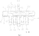
Fig. 1 is a front view of a six-way directional valve according to embodiments of the present disclosure; -
Fig. 2 is a left view of a six-way directional valve according to embodiments of the present disclosure; -
Fig. 3 is a sectional view of the six-way directional valve taken along line A-A shown inFig. 2 ; -
Fig. 4 is a schematic view of a connection between the six-way directional valve according to embodiments of the present disclosure and pipes; -
Fig. 5 is a schematic view of a connection between the six-way directional valve after directional control shown inFig. 4 and the pipes. - outdoor unit of
air conditioner 1000;
six-waydirectional valve 100; valve body 1; first connectingpipe 11; second connectingpipe 12; third connectingpipe 13; fourth connectingpipe 14; fifth connectingpipe 15; sixth connectingpipe 16; valve spool 2;first chamber 21;second chamber 22;third chamber 23;barrier block 24; slidingblock 25; connectingrod 26;valve chamber 3;valve cavity 4; pilot valve assembly 5;
outdoorunit output port 200;
outdoorunit input port 300;
compressor 400;air exhaust port 401;air return port 402;
outdoor heat exchanger 500;
L left; R right. - Reference will be made in detail to embodiments of the present disclosure. The embodiments described herein with reference to drawings are explanatory, illustrative, and used to generally understand the present disclosure. The embodiments shall not be construed to limit the present disclosure.
- In the specification, unless specified or limited otherwise, relative terms such as "transverse". "left", "right", should be construed to refer to the orientation as then described or as shown in the drawings under discussion. These relative terms are for convenience of description and do not require that the present disclosure be constructed or operated in a particular orientation.
- In the description of the present disclosure, unless specified or limited otherwise, the terms "mounted," "connected," and "couple" and variations thereof should be used broadly and encompass such as mechanical or electrical mountings, connections and couplings, also can be inner mountings, connections and couplings of two components, and further can be direct and indirect mountings, connections, and couplings, which can be understood by those skilled in the art according to the detail embodiment of the present disclosure.
- A six-way
directional valve 100 according to embodiments of the present disclosure will be described in the following with reference to drawings, which may be applied to an air conditioner, and used for switching a following direction of a refrigerant in the air conditioner. - As shown in
Figs. 1-5 , the six-waydirectional valve 100 according to the embodiments of the present disclosure may include a valve body 1, a valve spool 2 and a pilot valve assembly 5. - Specifically, the valve body 1 defines a
valve cavity 4 therein, the valve body 1 is provided with a first connectingpipe 11, a second connecting pipe, a third second connecting pipe, a fourth connecting pipe, a fifth connecting pipe and a sixth connectingpipe 16, the first connectingpipe 11 to the sixth connectingpipe 16 are communicated with other pipes in the air conditioner respectively, so as to facilitate the circulation of the refrigerant. - The valve spool 2 is movably disposed in the
valve cavity 4, that is, the valve spool 2 is movable in thevalve cavity 4, thus, by moving the valve spool 2 in thevalve cavity 4, a directional control function of the six-waydirectional valve 100 may be achieved, thus achieving the directional circulation of the refrigerant in the air conditioner. - Two
valve chambers 3 are defined between two moving ends of the valve spool 2 and inner circumferential walls of thevalve cavity 4, so that the valve spool 2 is allowed to be driven to move by a pressure difference between the twovalve chambers 3, that is, the movement action of the valve spool 2 in thevalve cavity 4 is driven by the pressure difference of the twovalve chambers 3. Specifically, when the pressure in onevalve chamber 3 of the twovalve chambers 3 is relatively higher, the valve spool 2 is allowed to move towards the other onevalve chamber 3 which has a relatively lower pressure therein, eventually a pressure balance is reached, thus moving the valve spool 2 by this manner, thereby achieving the directional control function of the six-waydirectional valve 100. - Specifically, the pilot valve assembly 5 is connected to the two
valve chambers 3, so as to switch the pressures in the twovalve chambers 3. For example, when the air conditioner needs to be switched between a refrigeration mode and a heating mode, the pilot valve assembly 5 switches the pressures in the twovalve chambers 3, so that the valve spool 2 is allowed to move towards thevalve chamber 3 having a lower pressure, thus achieving the directional control of the six-waydirectional valve 100, and changing the circulation direction of the refrigerant by this way, thereby achieving the refrigeration function or heating function of the air conditioner. - As shown in
Figs. 3-5 , afirst chamber 21 and asecond chamber 22 are defined between the valve spool 2 and a same side wall of thevalve cavity 4, and athird chamber 23 is defined between the valve spool 2 and an inner circumferential wall of thevalve cavity 4. The first connectingpipe 11 is normally communicated with thethird chamber 23, the third connectingpipe 13 is normally communicated with thefirst chamber 21, and the fifth connectingpipe 15 is normally communicated with thesecond chamber 22. That is, no matter whether a direction of the six-waydirectional valve 100 is controlled or not, the first connectingpipe 11 is always communicated with thethird chamber 23, the third connectingpipe 13 is always communicated with thefirst chamber 21, and the fifth connectingpipe 15 is always communicated with thesecond chamber 22. - The valve spool 2 moves so that one of the second connecting
pipe 12 and the sixth connectingpipe 16 is communicated with thethird chamber 23, thefirst chamber 21 is communicated with the second connectingpipe 12 or the fourth connectingpipe 14, thesecond chamber 22 is communicated with the fourth connectingpipe 14 or the sixth connectingpipe 16. That is, when the second connectingpipe 12 is communicated with thethird chamber 23, thefirst chamber 21 is communicated with the fourth connectingpipe 14, and thesecond chamber 22 is communicated with the sixth connectingpipe 16. When the sixth connectingpipe 16 is communicated with thethird chamber 23, the second connectingpipe 12 is communicated with thefirst chamber 21, and the fourth connectingpipe 14 is communicated with thesecond chamber 22. - Specifically, the pilot valve assembly 5 switches the pressure in the two
valve chambers 3, so that the valve spool 2 is allowed to move towards thevalve chamber 3 having the lower pressure. For example, when the valve spool 2 moves to right, as shown inFigs. 3 and4 , at this moment, the first connectingpipe 11 and the second connectingpipe 12 are communicated with thethird chamber 23, the third connectingpipe 13 and the fourth connectingpipe 14 are communicated with thefirst chamber 21, and the fifth connectingpipe 15 and the sixth connectingpipe 16 are communicated with thesecond chamber 22. When the valve spool 2 moves to left, as shown inFig. 5 , the first connectingpipe 11 and the sixth connectingpipe 16 are communicated with thethird chamber 23, the second connectingpipe 12 and the third connectingpipe 13 are communicated with thefirst chamber 21, the fourth connectingpipe 14 and the fifth connectingpipe 15 are communicated with thesecond chamber 22. It should be understood that, the left and right movements of the valve spool 2 are just explanatory descriptions according toFig. 3- Fig. 5 , and shall not be construed as a limit to the valve spool 2. In order to facilitate the description, the movements of the valve spool 2 mentioned in below are all explanatively described by the left or right movement. - It should be noted that, for facilitating clearly describing the directional principle of the six-way
directional valve 100, the six-waydirectional valve 100 will be described in the following accompanying an air conditioner. The air conditioner includes anoutdoor unit 1000 for the air conditioner and an indoor unit for the air conditioner. In which, theoutdoor unit 1000 has an outdoorunit output port 200 and an outdoorunit input port 300. Theoutdoor unit 1000 includes acompressor 400, the above-mentioned six-waydirectional valve 100 and anoutdoor heat exchanger 500. In which, the first connectingpipe 11 is communicated with anair exhaust port 401 of thecompressor 400, the second connectingpipe 12 is communicated with the outdoorunit output port 200, the fourth connectingpipe 14 is communicated with anair return port 402 of thecompressor 400, the fifth connectingpipe 15 is communicated with the outdoorunit input port 300, and both ends of theoutdoor heat exchanger 500 are respectively communicated with the third connectingpipe 13 and the sixth connectingpipe 16. - As shown in
Fig. 3 andFig. 4 , when the air conditioner is in the heating mode, the pilot valve assembly 5 switches the pressures in the twovalve chambers 3, so that the valve spool 2 moves to right, at the moment the first connectingpipe 11 and the second connectingpipe 12 are communicated with thethird chamber 23, the third connectingpipe 13 and the fourth connectingpipe 14 are communicated with thefirst chamber 21, and the fifth connectingpipe 15 and the sixth connectingpipe 16 are communicated with thesecond chamber 22. The refrigerant with a high pressure and a high temperature exhausted from theexhaust port 401 of thecompressor 400 enters thethird chamber 23 through the first connectingpipe 11, then flowing out from the second connectingpipe 12, entering the indoor unit for the air conditioner through the outdoorunit output port 200, and exchanging heat with the indoor environment in the indoor unit for the air conditioner to improve the indoor temperature. Then the refrigerant exhausted from the indoor unit for the air conditioner enters thesecond chamber 22 through the outdoorunit input port 300 and the fifth connectingpipe 15, subsequently enters theoutdoor heat exchanger 500 through the sixth connectingpipe 16, and exchanges heat with the outdoor environment in theoutdoor heat exchanger 500. And then the refrigerant enters thefirst chamber 21 through the third connectingpipe 13 after flowing out from theoutdoor heat exchanger 500, and returns to thecompressor 400 through the fourth connectingpipe 14 and theair return port 402 of thecompressor 400. The refrigerant circulates like this to form the heating circulation. - As shown in
Fig. 5 , when the air conditioner is in the refrigeration mode, the pilot valve assembly 5 switches the pressures in the twovalve chambers 3, so that the valve spool 2 moves to the left, at the moment the first connectingpipe 11 and the sixth connectingpipe 16 are communicated with thethird chamber 23, the second connectingpipe 12 and the third connectingpipe 13 are communicated with thefirst chamber 21, and the fourth connectingpipe 14 and the fifth connectingpipe 15 are communicated with thesecond chamber 22. The refrigerant with a high pressure and high temperature exhausted from theexhaust port 401 of thecompressor 400 enters thethird chamber 23 through the first connectingpipe 11, then flows out from the sixth connectingpipe 16, enters theoutdoor heat exchanger 500, and exchanges heat with the outdoor environment in theoutdoor heat exchanger 500. Then after flowing out from theoutdoor heat exchanger 500, the refrigerant enters thefirst chamber 21 through the third connectingpipe 13, subsequently flows out from the second connectingpipe 12, and enters the indoor unit for the air conditioner through the outdoorunit output port 200. After flowing out from the indoor unit for the air conditioner, the refrigerant enters into thesecond chamber 22 through the outdoorunit input port 300 and the fifth connectingpipe 15, then flows out from the fourth connectingpipe 14, and returns to thecompressor 400 through theair return port 402 of thecompressor 400. The refrigerant circulates like this to form the refrigeration circulation. - The first connecting
pipe 11 to the sixth connectingpipe 16 are disposed to the six-waydirectional valve 100 according to the embodiments of the present disclosure, and the valve spool 2 is disposed movably in thevalve cavity 4 to achieve the directional control function of the six-waydirectional valve 100, thus facilitating the directional circulation of the refrigerant in the pipes where the six-waydirectional valve 100 is, and avoiding using a plurality of four-way valves (to achieve the same effect as the six-way directional valve 100) in the pipes, which reduces the cost of the directional valve to some extent and simplifies the connection of the pipes in the air conditioner. - According to some embodiments of the present disclosure, the valve spool 2 includes two barrier blocks 24 spaced apart from each other and a sliding
block 25. In which,valve chambers 3 are defined between the two barrier blocks 24 spaced apart and the inner circumferential wall of thevalve cavity 4, thereby facilitating the valve spool 2 moving in thevalve cavity 4 to achieve the directional control of the six-waydirectional valve 100. - The sliding
block 25 is disposed between the two barrier blocks 24, the slidingblock 25 is connected to the two barrier blocks 24 through a connectingrod 26, thefirst chamber 21 and thesecond chamber 22 are defined between the slidingblock 25 and the same side wall of thevalve cavity 4, and thethird chamber 23 is defined between the slidingblock 25, two connectingrods 26, the two barrier blocks 24 and the inner circumferential wall of thevalve cavity 4. Specifically, after that the pilot valve assembly 5 switches the pressures in the twovalve chambers 3, a pressure in thevalve chamber 3 having a higher pressure drives the barrier blocks 24, and the barrier blocks 24 drive the slidingblock 25 to move towards thevalve chamber 3 having a lower pressure, so as to achieve connections between thefirst chamber 21, thesecond chamber 22 and thethird chamber 23 and the corresponding first connectingpipe 11 to the sixth connectingpipe 16 respectively, thereby achieving the directional control of the six-waydirectional valve 100. - Optionally, the two barrier blocks 24, the sliding
block 25 and the two connectingrods 26 are configured as an integrally formed member, thus not only facilitating the production, processing and manufacturing of the barrier blocks 24, the slidingblock 25 and the two connectingrods 26, but also saving the production cost of the valve spool 2, in the meanwhile improving the strength of the connection among the barrier blocks 24, the slidingblock 25 and the two connectingrods 26 to some extent, and prolonging the service life of the valve 2. - According to some embodiments of the present disclosure, as shown in
Fig. 1 andFigs. 3-5 , the first connectingpipe 11 is disposed to a first side wall of the valve body 1, the second connectingpipe 12 to the sixth connectingpipe 16 are respectively disposed to a second side wall of the valve body 1 opposite to the first side wall and are arranged successively, that is, the first connectingpipe 11 are disposed oppositely to the second connecting pipe to the sixth connecting pipe 12-16, thereby facilitating connections between the first connectingpipe 11 to the sixth connectingpipe 16 and the correspondingfirst chamber 21 to thethird chamber 23 respectively, so as to achieve the directional control of the six-waydirectional valve 100. - Optionally, the valve body 1 may have a circular cross section, as shown in
Fig. 2 , thereby facilitating the communication between the six-waydirectional valve 100 and other pipes in an air conditioner. - Reference throughout this specification to "an embodiment," "some embodiments," "one embodiment", "another example," "an example," "a specific example," or "some examples," means that a particular feature, structure, material, or characteristic described in connection with the embodiment or example is included in at least one embodiment or example of the present disclosure. Thus, the appearances of the phrases such as "in some embodiments," "in one embodiment", "in an embodiment", "in another example," "in an example," "in a specific example," or "in some examples," in various places throughout this specification are not necessarily referring to the same embodiment or example of the present disclosure. Furthermore, the particular features, structures, materials, or characteristics may be combined in any suitable manner in one or more embodiments or examples.
- Although explanatory embodiments have been shown and described, it would be appreciated by those skilled in the art that the above embodiments cannot be construed to limit the present disclosure, and changes, alternatives, and modifications can be made in the embodiments without departing from spirit, principles and scope of the present disclosure.
Claims (5)
- A six-way directional valve comprising:a valve body, defining a valve cavity therein and provided with a first connecting pipe, a second connecting pipe, a third second connecting pipe, a fourth connecting pipe, a fifth connecting pipe and a sixth connecting pipe;a valve spool, movably disposed in the valve cavity, wherein two valve chambers are defined between two moving ends of the valve spool and an inner circumferential wall of the valve cavity, so that the valve spool is driven to move by a pressure difference between the two valve chambers, a first chamber and a second chamber are defined between the valve spool and a same side wall of the valve cavity, a third chamber is defined between the valve spool and the inner circumferential wall of the valve cavity, the first connecting pipe is normally communicated with the third chamber, the third connecting pipe is normally communicated with the first chamber, the fifth connecting pipe is normally communicated with the second chamber, the valve spool moves so that one of the second connecting pipe and the sixth connecting pipe is communicated with the third chamber, the first chamber is communicated with the second connecting pipe or the fourth connecting pipe, and the second chamber is communicated with the fourth connecting pipe or the sixth connecting pipe; anda pilot valve assembly, connected with the two valve chambers so as to switch pressures in the two valve chambers.
- The six-way directional valve according to claim 1, wherein the valve spool comprises:two barrier blocks spaced apart from each other, the two valve chambers being defined between the two barrier blocks and the inner circumferential wall of the valve cavity; anda sliding block, disposed between the two barrier blocks and connected to the two barrier blocks through a connecting rod, the first chamber and the second chamber being defined between the sliding block and the same side wall of the valve cavity, and the third chamber being defined between the sliding block, two connecting rods, the two barrier blocks and the inner circumferential wall of the valve cavity.
- The six-way directional valve according to claim 2, wherein the two barrier blocks, the sliding block and the two connecting rods are configured as an integrally formed member.
- The six-way directional valve according to anyone of claims 1-3, wherein the first connecting pipe is disposed to a first side wall of the valve body, and the second connecting pipe to the sixth connecting pipe are disposed to a second side wall of the valve body opposite to the first side wall and are arranged successively.
- The six-way directional valve according to anyone of claims 1-4, wherein the valve body has a circular cross section.
Applications Claiming Priority (3)
| Application Number | Priority Date | Filing Date | Title |
|---|---|---|---|
| CN201520367442.XU CN204729675U (en) | 2015-06-01 | 2015-06-01 | Six-way transfer valve |
| CN201510292204.1A CN104896139A (en) | 2015-06-01 | 2015-06-01 | Six-way reversing valve |
| PCT/CN2015/082247 WO2016192148A1 (en) | 2015-06-01 | 2015-06-24 | Six-way reversing valve |
Publications (2)
| Publication Number | Publication Date |
|---|---|
| EP3205910A1 true EP3205910A1 (en) | 2017-08-16 |
| EP3205910A4 EP3205910A4 (en) | 2018-05-16 |
Family
ID=57439938
Family Applications (1)
| Application Number | Title | Priority Date | Filing Date |
|---|---|---|---|
| EP15893804.3A Withdrawn EP3205910A4 (en) | 2015-06-01 | 2015-06-24 | Six-way reversing valve |
Country Status (3)
| Country | Link |
|---|---|
| US (1) | US10132417B2 (en) |
| EP (1) | EP3205910A4 (en) |
| WO (1) | WO2016192148A1 (en) |
Families Citing this family (3)
| Publication number | Priority date | Publication date | Assignee | Title |
|---|---|---|---|---|
| WO2019215916A1 (en) * | 2018-05-11 | 2019-11-14 | 三菱電機株式会社 | Refrigeration cycle system |
| CN114992357A (en) * | 2021-03-01 | 2022-09-02 | 浙江盾安人工环境股份有限公司 | Reversing valve and assembling method thereof |
| EP4328470A4 (en) * | 2021-05-20 | 2025-02-26 | Zhejiang Dunan Artificial Environment Co., Ltd. | REVERSIBLE SOLENOID VALVE AND AIR CONDITIONING UNIT EQUIPPED THEREWITH |
Family Cites Families (13)
| Publication number | Priority date | Publication date | Assignee | Title |
|---|---|---|---|---|
| JPH07324844A (en) * | 1994-05-31 | 1995-12-12 | Sanyo Electric Co Ltd | Six-way switching valve and refrigerator using the same |
| JPH08170865A (en) * | 1994-12-19 | 1996-07-02 | Sanyo Electric Co Ltd | Switching valve for heat pump air conditioner |
| JPH11201304A (en) | 1998-01-12 | 1999-07-30 | Ntn Corp | Selector valve and resin parts |
| JPH11325634A (en) * | 1998-05-20 | 1999-11-26 | Fujitsu General Ltd | Air conditioner four-way valve cooling system |
| JP2000046213A (en) * | 1998-07-28 | 2000-02-18 | Calsonic Corp | Flow path switching valve |
| JP4826808B2 (en) * | 2007-05-16 | 2011-11-30 | 株式会社富士通ゼネラル | Refrigerant circuit |
| CN101776162B (en) | 2010-02-05 | 2011-06-15 | 清华大学 | Four-way valve for switching natural cooling, refrigerating and heating modes |
| CN102588627B (en) | 2011-01-06 | 2015-08-05 | 浙江三花制冷集团有限公司 | A kind of air conditioning reversing valve and air-conditioning system |
| CN201983529U (en) | 2011-03-03 | 2011-09-21 | 山东朗进科技股份有限公司 | Automobile air conditioning system and six-way valve |
| CN102853114B (en) | 2011-06-29 | 2014-12-17 | 浙江盾安机械有限公司 | Two-position six-way valve for electric vehicle air conditionings and heat-pump heating and cooling air conditioning system for electric vehicles |
| CN203374885U (en) | 2013-07-25 | 2014-01-01 | 珠海格力电器股份有限公司 | Four-way valve and air conditioner |
| CN104390283B (en) * | 2014-10-21 | 2017-06-30 | 广东美的暖通设备有限公司 | Multi-gang air-conditioner device and its outdoor machine system |
| CN104896612A (en) | 2015-06-01 | 2015-09-09 | 广东美的暖通设备有限公司 | Air conditioning outdoor unit and air conditioner |
-
2015
- 2015-06-24 WO PCT/CN2015/082247 patent/WO2016192148A1/en not_active Ceased
- 2015-06-24 EP EP15893804.3A patent/EP3205910A4/en not_active Withdrawn
- 2015-06-24 US US15/325,794 patent/US10132417B2/en active Active
Also Published As
| Publication number | Publication date |
|---|---|
| US10132417B2 (en) | 2018-11-20 |
| WO2016192148A1 (en) | 2016-12-08 |
| EP3205910A4 (en) | 2018-05-16 |
| US20170138488A1 (en) | 2017-05-18 |
Similar Documents
| Publication | Publication Date | Title |
|---|---|---|
| EP3306155B1 (en) | Six-way reversing valve, and air-conditioning outdoor unit, and air conditioner having same | |
| US10253992B2 (en) | Multi-split air-conditioner and outdoor unit system thereof | |
| CN104896612A (en) | Air conditioning outdoor unit and air conditioner | |
| EP3309432B1 (en) | Reversing valve and cooling system having same | |
| CN104896143A (en) | Six-way reversing valve and air conditioning outdoor unit and air conditioner with same | |
| CN104964490B (en) | Four-way valve and air-conditioning system | |
| JP5997491B2 (en) | Four-way selector valve | |
| US10132417B2 (en) | Six-way directional valve | |
| EP3182021A1 (en) | Air-conditioning outdoor unit and air conditioner | |
| CN109973682A (en) | Solenoid directional control valve and refrigeration system with it | |
| CN111120690B (en) | Four-way valve | |
| JP5982871B2 (en) | Four-way valve and heat pump device equipped with it | |
| CN204729675U (en) | Six-way transfer valve | |
| JP2016029323A (en) | Four-way selector valve and refrigerator | |
| CN106288543B (en) | Five-way reversing valve and air conditioning system | |
| CN107166819B (en) | an air conditioning system | |
| CN104896139A (en) | Six-way reversing valve | |
| CN204757182U (en) | Air condensing units and air conditioner | |
| JP2012159101A (en) | Four-way switching valve | |
| JP2016044777A (en) | Flow passage selector valve and refrigeration cycle using the same | |
| CN104180020A (en) | Reversing valve for refrigerating system and pilot valve of reversing valve | |
| CN107642835B (en) | Multi-split outdoor unit and multi-split with same | |
| JP6329513B2 (en) | Switching valve and refrigeration cycle system | |
| CN207540030U (en) | Multi-connected machine outdoor unit and with its multi-connected machine | |
| JP2012202588A (en) | Four-way valve and heat pump device with the same |
Legal Events
| Date | Code | Title | Description |
|---|---|---|---|
| STAA | Information on the status of an ep patent application or granted ep patent |
Free format text: STATUS: THE INTERNATIONAL PUBLICATION HAS BEEN MADE |
|
| PUAI | Public reference made under article 153(3) epc to a published international application that has entered the european phase |
Free format text: ORIGINAL CODE: 0009012 |
|
| STAA | Information on the status of an ep patent application or granted ep patent |
Free format text: STATUS: REQUEST FOR EXAMINATION WAS MADE |
|
| 17P | Request for examination filed |
Effective date: 20170324 |
|
| AK | Designated contracting states |
Kind code of ref document: A1 Designated state(s): AL AT BE BG CH CY CZ DE DK EE ES FI FR GB GR HR HU IE IS IT LI LT LU LV MC MK MT NL NO PL PT RO RS SE SI SK SM TR |
|
| AX | Request for extension of the european patent |
Extension state: BA ME |
|
| A4 | Supplementary search report drawn up and despatched |
Effective date: 20180412 |
|
| RIC1 | Information provided on ipc code assigned before grant |
Ipc: F16K 11/07 20060101ALI20180406BHEP Ipc: F16K 31/122 20060101ALI20180406BHEP Ipc: F16K 11/065 20060101AFI20180406BHEP Ipc: F16K 31/124 20060101ALI20180406BHEP |
|
| DAV | Request for validation of the european patent (deleted) | ||
| DAX | Request for extension of the european patent (deleted) | ||
| STAA | Information on the status of an ep patent application or granted ep patent |
Free format text: STATUS: EXAMINATION IS IN PROGRESS |
|
| 17Q | First examination report despatched |
Effective date: 20190214 |
|
| STAA | Information on the status of an ep patent application or granted ep patent |
Free format text: STATUS: THE APPLICATION IS DEEMED TO BE WITHDRAWN |
|
| 18D | Application deemed to be withdrawn |
Effective date: 20200603 |