EP3205889B1 - Serial-parallel hydraulic valve with logic switching element - Google Patents
Serial-parallel hydraulic valve with logic switching element Download PDFInfo
- Publication number
- EP3205889B1 EP3205889B1 EP17155506.3A EP17155506A EP3205889B1 EP 3205889 B1 EP3205889 B1 EP 3205889B1 EP 17155506 A EP17155506 A EP 17155506A EP 3205889 B1 EP3205889 B1 EP 3205889B1
- Authority
- EP
- European Patent Office
- Prior art keywords
- switching element
- channel
- logic switching
- pressure
- valve
- Prior art date
- Legal status (The legal status is an assumption and is not a legal conclusion. Google has not performed a legal analysis and makes no representation as to the accuracy of the status listed.)
- Active
Links
Images



Classifications
-
- F—MECHANICAL ENGINEERING; LIGHTING; HEATING; WEAPONS; BLASTING
- F15—FLUID-PRESSURE ACTUATORS; HYDRAULICS OR PNEUMATICS IN GENERAL
- F15B—SYSTEMS ACTING BY MEANS OF FLUIDS IN GENERAL; FLUID-PRESSURE ACTUATORS, e.g. SERVOMOTORS; DETAILS OF FLUID-PRESSURE SYSTEMS, NOT OTHERWISE PROVIDED FOR
- F15B11/00—Servomotor systems without provision for follow-up action; Circuits therefor
- F15B11/16—Servomotor systems without provision for follow-up action; Circuits therefor with two or more servomotors
- F15B11/20—Servomotor systems without provision for follow-up action; Circuits therefor with two or more servomotors controlling several interacting or sequentially-operating members
-
- F—MECHANICAL ENGINEERING; LIGHTING; HEATING; WEAPONS; BLASTING
- F15—FLUID-PRESSURE ACTUATORS; HYDRAULICS OR PNEUMATICS IN GENERAL
- F15B—SYSTEMS ACTING BY MEANS OF FLUIDS IN GENERAL; FLUID-PRESSURE ACTUATORS, e.g. SERVOMOTORS; DETAILS OF FLUID-PRESSURE SYSTEMS, NOT OTHERWISE PROVIDED FOR
- F15B11/00—Servomotor systems without provision for follow-up action; Circuits therefor
- F15B11/16—Servomotor systems without provision for follow-up action; Circuits therefor with two or more servomotors
- F15B11/161—Servomotor systems without provision for follow-up action; Circuits therefor with two or more servomotors with sensing of servomotor demand or load
-
- F—MECHANICAL ENGINEERING; LIGHTING; HEATING; WEAPONS; BLASTING
- F15—FLUID-PRESSURE ACTUATORS; HYDRAULICS OR PNEUMATICS IN GENERAL
- F15B—SYSTEMS ACTING BY MEANS OF FLUIDS IN GENERAL; FLUID-PRESSURE ACTUATORS, e.g. SERVOMOTORS; DETAILS OF FLUID-PRESSURE SYSTEMS, NOT OTHERWISE PROVIDED FOR
- F15B13/00—Details of servomotor systems ; Valves for servomotor systems
- F15B13/02—Fluid distribution or supply devices characterised by their adaptation to the control of servomotors
- F15B13/06—Fluid distribution or supply devices characterised by their adaptation to the control of servomotors for use with two or more servomotors
-
- F—MECHANICAL ENGINEERING; LIGHTING; HEATING; WEAPONS; BLASTING
- F15—FLUID-PRESSURE ACTUATORS; HYDRAULICS OR PNEUMATICS IN GENERAL
- F15B—SYSTEMS ACTING BY MEANS OF FLUIDS IN GENERAL; FLUID-PRESSURE ACTUATORS, e.g. SERVOMOTORS; DETAILS OF FLUID-PRESSURE SYSTEMS, NOT OTHERWISE PROVIDED FOR
- F15B13/00—Details of servomotor systems ; Valves for servomotor systems
- F15B13/02—Fluid distribution or supply devices characterised by their adaptation to the control of servomotors
- F15B13/06—Fluid distribution or supply devices characterised by their adaptation to the control of servomotors for use with two or more servomotors
- F15B13/08—Assemblies of units, each for the control of a single servomotor only
-
- F—MECHANICAL ENGINEERING; LIGHTING; HEATING; WEAPONS; BLASTING
- F15—FLUID-PRESSURE ACTUATORS; HYDRAULICS OR PNEUMATICS IN GENERAL
- F15B—SYSTEMS ACTING BY MEANS OF FLUIDS IN GENERAL; FLUID-PRESSURE ACTUATORS, e.g. SERVOMOTORS; DETAILS OF FLUID-PRESSURE SYSTEMS, NOT OTHERWISE PROVIDED FOR
- F15B18/00—Parallel arrangements of independent servomotor systems
-
- F—MECHANICAL ENGINEERING; LIGHTING; HEATING; WEAPONS; BLASTING
- F15—FLUID-PRESSURE ACTUATORS; HYDRAULICS OR PNEUMATICS IN GENERAL
- F15B—SYSTEMS ACTING BY MEANS OF FLUIDS IN GENERAL; FLUID-PRESSURE ACTUATORS, e.g. SERVOMOTORS; DETAILS OF FLUID-PRESSURE SYSTEMS, NOT OTHERWISE PROVIDED FOR
- F15B2211/00—Circuits for servomotor systems
- F15B2211/20—Fluid pressure source, e.g. accumulator or variable axial piston pump
- F15B2211/205—Systems with pumps
- F15B2211/2053—Type of pump
- F15B2211/20538—Type of pump constant capacity
-
- F—MECHANICAL ENGINEERING; LIGHTING; HEATING; WEAPONS; BLASTING
- F15—FLUID-PRESSURE ACTUATORS; HYDRAULICS OR PNEUMATICS IN GENERAL
- F15B—SYSTEMS ACTING BY MEANS OF FLUIDS IN GENERAL; FLUID-PRESSURE ACTUATORS, e.g. SERVOMOTORS; DETAILS OF FLUID-PRESSURE SYSTEMS, NOT OTHERWISE PROVIDED FOR
- F15B2211/00—Circuits for servomotor systems
- F15B2211/30—Directional control
- F15B2211/305—Directional control characterised by the type of valves
- F15B2211/30525—Directional control valves, e.g. 4/3-directional control valve
- F15B2211/3053—In combination with a pressure compensating valve
- F15B2211/30535—In combination with a pressure compensating valve the pressure compensating valve is arranged between pressure source and directional control valve
-
- F—MECHANICAL ENGINEERING; LIGHTING; HEATING; WEAPONS; BLASTING
- F15—FLUID-PRESSURE ACTUATORS; HYDRAULICS OR PNEUMATICS IN GENERAL
- F15B—SYSTEMS ACTING BY MEANS OF FLUIDS IN GENERAL; FLUID-PRESSURE ACTUATORS, e.g. SERVOMOTORS; DETAILS OF FLUID-PRESSURE SYSTEMS, NOT OTHERWISE PROVIDED FOR
- F15B2211/00—Circuits for servomotor systems
- F15B2211/30—Directional control
- F15B2211/305—Directional control characterised by the type of valves
- F15B2211/3056—Assemblies of multiple valves
- F15B2211/3059—Assemblies of multiple valves having multiple valves for multiple output members
- F15B2211/30595—Assemblies of multiple valves having multiple valves for multiple output members with additional valves between the groups of valves for multiple output members
-
- F—MECHANICAL ENGINEERING; LIGHTING; HEATING; WEAPONS; BLASTING
- F15—FLUID-PRESSURE ACTUATORS; HYDRAULICS OR PNEUMATICS IN GENERAL
- F15B—SYSTEMS ACTING BY MEANS OF FLUIDS IN GENERAL; FLUID-PRESSURE ACTUATORS, e.g. SERVOMOTORS; DETAILS OF FLUID-PRESSURE SYSTEMS, NOT OTHERWISE PROVIDED FOR
- F15B2211/00—Circuits for servomotor systems
- F15B2211/30—Directional control
- F15B2211/31—Directional control characterised by the positions of the valve element
- F15B2211/3122—Special positions other than the pump port being connected to working ports or the working ports being connected to the return line
Definitions
- the present invention finds application in hydraulic valves and its object is the implementation of a dedicated hydraulic circuit for lifting applications in the presence of hydraulic valves with multiple functions intended for operating machines, such as front loaders, shovels, buckets.
- the invention relates to a logic element insertable inside said hydraulic circuit of control valves for utilities, wherein said logic element is capable of ensuring an overall operation of the circuit in series or in parallel depending on the operating conditions of the valve.
- the invention provides for multiple possibilities to solve and manage these operating conditions.
- EP 2 381 115 A describes a hydraulic circuit for a construction machine.
- the present invention aims to find a solution that allows, in a single circuit, the benefits of both configurations described to be obtained, as a function of the working conditions.
- One object of the present invention is to solve the limits of circuits for hydraulic valves in "series” ( fig. 1 ) and “parallel” ( fig. 2 ) intended for front loading circuits described above, with a simple, rational and rather cost-effective solution.
- the logic switching element ensures an overall operation of the circuit in series or in parallel depending on the plant operating conditions.
- the logic switching element is controlled by a sequence valve or by a pressure relief valve.
- the circuit ensures a more stable operation upon switching from series to parallel circuit and vice versa, thereby delegating the calibration of the sequence valve or the spool position as responsible for the switching of the logic element.
- valve and mixed series-parallel hydraulic circuit object of the present invention which is defined by the claims below.
- Fig. 3 shows the basic construction of the logic element E.
- the latter reaches the second position, which involves closing between channel S and P1 and the simultaneous opening of the parallel channel P towards branch P1.
- channel S is set to discharge by the connection with T.
- a control channel 1 is also part of the logic element E, which copies the signal from branch P and brings it on one side of the logic element. Furthermore, spring 2, which has the function of keeping the logic element in that neutral position and the calibration of which determines the pressure value P required for the switching of the logic element E.
- this logic element E is inserted in a complete hydraulic circuit for front loader, implementing in this way the circuit shown in Fig. 1 and 2 .
- Fig. 4 proposes the scheme in fig. 3 but with a different constructive solution.
- the logic element E1 is coupled with a sequence valve VS.
- Valve VS consists of a distributor CS associated with a spring 9, a pressure relief valve VM and relative connections.
- a control line 7 including two chokes 4 and 8 is added in the illustrated solution.
- spring 2a changes function with respect to spring 2 seen in fig. 3 .
- the logic element E1 in rest configuration involves the connection of S with P1, and since the pressure value on P is reported on both sides of the logic element by virtue of connections 1 and 6, this is guaranteed by the second spring 2a.
- the calibration value of valve VM set onto spring 5 is reached on P, this opens the connection of the control line 7 towards the discharge.
- distributor CS opens in position to set both branch controls 10 and 11 to discharge.
- the pressure difference generated by choke 4 causes the displacement of the logic element E1 to a second position, as the pressure value on channel 6 is lower than the value on channel 1.
- this logic element E1 is inserted in a complete hydraulic circuit for front loader, implementing in this way the circuit shown in Fig. 1 and 2 .
- the sequence valve VS described in fig. 4 is schematized.
- the logic element E2 consists of a 6-way, 2 positions distributor. Connection 6a and 12 is added to channels P, S, T, P1, which remain the same as regards the connections as compared to the solutions shown above. In neutral position of the logic element, the two signals 6a and 12 are closed in the logic element. In switching position of element E2, channels 6a and 12 are connected through the element.
- Spring 2a is the same as in solution in fig. 4 , as well as channel 7, choke 4 and also the pressure relief valve VM and relative spring 5.
- the logic element E2 in rest configuration involves the connection of S with P1, and since the pressure value on P is reported on both sides of the logic element by virtue of connections 1 and 6, said connection is guaranteed by spring 2a. Once the calibration value of valve VM set onto spring 5 is reached on P, this opens the connection of the control line 7 towards the channel 14, not necessarily to discharge:
- Channel 14 is interrupted, the pressure increase on channels 14, 12, 6a, 6 results in the switching of the logic element E2 to neutral.
- Channel 13 is essential to prevent the increased pressure from reopening valve VM without having switched the logic element E2.
- this logic element E2 is inserted in a complete hydraulic circuit for front loader, implementing in this way the circuit shown in Fig. 1 and 2 .
- Fig. 6 the logic element E1 in fig. 4 is inserted in a complete hydraulic circuit for frontal loader similar to that in fig. 4A , but in this case repeated for a circuit with multiple sections, in this case 3.
Landscapes
- Engineering & Computer Science (AREA)
- Physics & Mathematics (AREA)
- Fluid Mechanics (AREA)
- Mechanical Engineering (AREA)
- General Engineering & Computer Science (AREA)
- Fluid-Pressure Circuits (AREA)
Description
- The present invention finds application in hydraulic valves and its object is the implementation of a dedicated hydraulic circuit for lifting applications in the presence of hydraulic valves with multiple functions intended for operating machines, such as front loaders, shovels, buckets.
- More precisely, the invention relates to a logic element insertable inside said hydraulic circuit of control valves for utilities, wherein said logic element is capable of ensuring an overall operation of the circuit in series or in parallel depending on the operating conditions of the valve. The invention provides for multiple possibilities to solve and manage these operating conditions.
-
EP 2 381 115 A - A common problem of the existing open center hydraulic circuits in "series" configuration (as shown in
figure 1 ) is the following: let's assume that the elements of the hydraulic distributor actuate cylinders, in the case of simultaneous use of two or more sections, if one these cylinders reached the end of stroke, the others stop as well. - Similarly, for a hydraulic valve entirely in "parallel" configuration (see
figure 2 ), in case of flow demand of multiple elements (utilities), the distribution of the same among the elements depends on the pressures generated by the loads and therefore potentially, in certain situations, simultaneous movements are not guaranteed. - Both series/parallel circuits, have advantages and drawbacks. The present invention aims to find a solution that allows, in a single circuit, the benefits of both configurations described to be obtained, as a function of the working conditions.
- One object of the present invention is to solve the limits of circuits for hydraulic valves in "series" (
fig. 1 ) and "parallel" (fig. 2 ) intended for front loading circuits described above, with a simple, rational and rather cost-effective solution. - These and other objects are achieved with the features of the invention described in the independent claim 1. The dependent claims describe preferred and/or particularly advantageous aspects of the invention.
- With this solution, the logic switching element ensures an overall operation of the circuit in series or in parallel depending on the plant operating conditions.
- According to preferred embodiments of the invention, the logic switching element is controlled by a sequence valve or by a pressure relief valve.
- With this solution, the circuit ensures a more stable operation upon switching from series to parallel circuit and vice versa, thereby delegating the calibration of the sequence valve or the spool position as responsible for the switching of the logic element.
- Said objects and advantages are all achieved by the valve and mixed series-parallel hydraulic circuit object of the present invention, which is defined by the claims below.
- This and other features will become more apparent from the following description of some of the configurations, illustrated purely by way of example in the accompanying drawings, in which:
-
FIG. 1 shows a hydraulic circuit for front loader with 2 sections in "series" configuration; -
FIG. 2 shows a hydraulic circuit for front loader with 2 sections in "parallel" configuration; -
FIG. 3 schematically shows the logic element to be included in the circuit; -
FIG. 3A shows the diagram of a hydraulic circuit for front loader with 2 sections with the integration of the logic element schematized inFig. 3 . -
FIG. 4 schematically shows the logic element controlled by a sequence valve; -
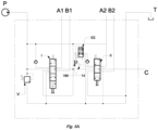
FIG. 4A shows the diagram of a hydraulic circuit for front loader with 2 sections with the integration of the logic element controlled by a sequence valve schematized inFig. 4 . -
FIG. 5 schematically shows the 6-way, 2-position logic element controlled by a pressure relief valve; -
FIG. 5A shows the diagram of a hydraulic circuit for front loader with 2 sections with the integration of the 6-way, 2-position logic element controlled by a pressure relief valve schematized inFig. 5 . -
FIG. 6 shows the diagram of a hydraulic circuit for front loader with the integration of the logic element controlled by a sequence valve shown inFig. 4 but repeated for a 3-section circuit. - With reference to the accompanying figures,
Fig. 3 shows the basic construction of the logic element E. - It is a 4-way, 2-position distributor, in which
spring 2 keeps the logic element in the rest position, where channel S, or series, is connected with the branch named P1. At the same time, the pressure channel P, i.e. parallel, is isolated from the logic element E, as the discharge channel T is isolated. - In the switching step of the distributor, the latter reaches the second position, which involves closing between channel S and P1 and the simultaneous opening of the parallel channel P towards branch P1. In this case, channel S is set to discharge by the connection with T.
- A control channel 1 is also part of the logic element E, which copies the signal from branch P and brings it on one side of the logic element. Furthermore,
spring 2, which has the function of keeping the logic element in that neutral position and the calibration of which determines the pressure value P required for the switching of the logic element E. - In
Fig. 3A , this logic element E is inserted in a complete hydraulic circuit for front loader, implementing in this way the circuit shown inFig. 1 and 2 . - One can see where the various ways P, T, S, P1 of the logic element E described in
Fig. 3 are connected. -
Fig. 4 proposes the scheme infig. 3 but with a different constructive solution. The logic element E1 is coupled with a sequence valve VS. Valve VS consists of a distributor CS associated with a spring 9, a pressure relief valve VM and relative connections. A control line 7 including twochokes spring 2a changes function with respect tospring 2 seen infig. 3 . - The logic element E1 in rest configuration involves the connection of S with P1, and since the pressure value on P is reported on both sides of the logic element by virtue of
connections 1 and 6, this is guaranteed by thesecond spring 2a. Once the calibration value of valve VM set ontospring 5 is reached on P, this opens the connection of the control line 7 towards the discharge. Due to the pressure difference generated bychoke 8, distributor CS opens in position to set bothbranch controls choke 4 causes the displacement of the logic element E1 to a second position, as the pressure value onchannel 6 is lower than the value on channel 1. - If the pressure on branch 7 drops, VM is closed again, thereby interrupting the connection with the discharge. Closing the VM does not cause a new displacement of the logic element E1 since distributor CS remains in the discharge position of the signal due to the pressure difference on
signals signal 10 falls below the calibration of spring 9. In order for everything to work correctly, the pressure value of spring 9 must be lower than the value ofspring 5 of the valve VM. - In
Fig. 4A , this logic element E1 is inserted in a complete hydraulic circuit for front loader, implementing in this way the circuit shown inFig. 1 and 2 . The sequence valve VS described infig. 4 is schematized. - In this circuit, one can see the connections of the various ways P, T, S, P1 of the logic element E1 described in
fig. 4 , in addition to valve VS. - In
Fig. 5 , the logic element E2 consists of a 6-way, 2 positions distributor.Connection signals channels Spring 2a is the same as in solution infig. 4 , as well as channel 7,choke 4 and also the pressure relief valve VM andrelative spring 5. - The logic element E2 in rest configuration involves the connection of S with P1, and since the pressure value on P is reported on both sides of the logic element by virtue of
connections 1 and 6, said connection is guaranteed byspring 2a. Once the calibration value of valve VM set ontospring 5 is reached on P, this opens the connection of the control line 7 towards thechannel 14, not necessarily to discharge: - if
channel 14 is closed, the logic element E2 will not open on the spool downstream of the VM, - if
channel 14 is set to discharge through the spool, the pressure difference generated bychoke 4 causes the displacement of the logic element E2 to a second position, as the pressure value onchannel 6 is lower than the value on channel 1. - If the pressure on the control line 7 drops, VM is closed again, thereby interrupting the connection with
channel 14. Closing the VM does not cause a new displacement of the logic element E2 asconnection 6a with 12 in the logic element, which bypasses the VM, remains open. - If for some reason (that will be seen in
fig. 5A ), the connection ofchannel 14 is interrupted, the pressure increase onchannels Channel 13 is essential to prevent the increased pressure from reopening valve VM without having switched the logic element E2. - In
Fig. 5A , this logic element E2 is inserted in a complete hydraulic circuit for front loader, implementing in this way the circuit shown inFig. 1 and 2 . - In this circuit, one can see the connections of the various ways P, T, S, P1 of the logic element E2 described in
fig. 5 . - From this image it is clear that operation is also associated with the position of spool II.
Channel 14 is in fact closed by spool II when this is in the neutral position. Conversely, when spool II is controlled in one of the two positions,connection 14 is connected to the discharge of the distributor. - In
Fig. 6 , the logic element E1 infig. 4 is inserted in a complete hydraulic circuit for frontal loader similar to that infig. 4A , but in this case repeated for a circuit with multiple sections, in this case 3. - The operation obtained for 2 sections is therefore extensible also to distributors with n-sections.
Claims (10)
- Hydraulic directional valve, with mixed series (S) and parallel (P) hydraulic circuit made of two or more sections each comprising a spool (I, II, II) and which can be mutually connected by both series and parallel connections, said valve comprising series channel (S) and parallel channel (P) for series and parallel connection, respectively, said parallel channel corresponding to a pressure channel of the valve, characterized in that said valve comprises a logic switching element (E, E1, E2) comprising a distributor, wherein said logic switching element (E, E1, E2) in a neutral position connects the series channel (S) of said mixed series and parallel hydraulic circuit with a downstream pressure branch (P1) positioned downstream the logic switching element (E, E1, E2) and connecting to a spool (II) downstream of the logic switching element (E, E1, E2), and at the same time isolates a pressure branch of the parallel channel (P) of a parallel connection and of a discharge branch (T); wherein, when switching the distributor of the logic switching element (E, E1, E2), the latter reaches a second position, in which the series channel (S) is closed and simultaneously the parallel channel (P) is opened towards the downstream pressure branch (P1), and in said second position said series channel (S) is set to discharge by connection with the discharge branch (T), wherein the logic switching element (E) comprises a control channel (1) bringing the signal from the pressure channel (P) on one side of the logic switching element (E, E1, E2) and a spring (2; 2a) located on a side opposite to the one in which the pressure channel (P) is brought, wherein the logic switching element (E) is retained in said neutral position by the spring (2), a calibration value of said spring (2) determining the pressure value in the control channel (1) for switching of the logic switching element (E) from the neutral position to said second position.
- Valve according to claim 1, characterized in that said switching of the logic switching element (E1) is controlled by a sequence valve (VS) coupled with said logic switching element (E1), formed by a further distributor (CS) associated with a spring (9) and a pressure relief valve (VM); said sequence valve (VS) defines two different switching pressures of the logic switching element (E1) and the further distributor (CS):a. it opens once the calibration value of a further spring (5) of the pressure relief valve (VM) of said sequence valve (VS) is reached;b. it only closes when the pressure value on a first control signal (10) drops below the calibration of spring (9) associated with said further distributor (CS), the control signal (10) being opposed to the spring (9) of said further distributor (CS), the pressure value of the spring (9) of said further distributor (CS) being lower than the value of the further spring (5) of the pressure relief valve (VM).
- Valve according to claim 2, characterized in that it comprises a control line (7) comprising two chokes (4, 8), the further distributor (CS) having a second control signal (11) a first choke (8) being placed between the two control signals (10, 11) of the further distributor (CS), wherein, in resting configuration, said logic switching element (E1) connects the channel series (S) with the downstream pressure branch (P1) by the action of the spring (2a) of the logic switching element (E1), the value of the pressure channel (P) being shown on both sides of the logic switching element (E1) by said control channel (1) and a second control channel (6); said pressure relief valve (VM) is configured to open the connection of the control line (7) towards the discharge (T), once the calibration value of the pressure relief valve (VM) set on the spring (5) of the pressure relief valve (VM) is reached on the pressure channel (P):- the further distributor (CS) opens to discharge as a function of the pressure difference generated by the choke (8) on the two control signals (10, 11),- the pressure difference generated by a second choke (4) causes the displacement of the logic switching element (E1) to a second position, as the pressure value on the second control channel (6) is lower than the value on said control channel (1),- wherein closing the pressure relief valve (VM) does not cause a new displacement of the logic switching element (E1); the further distributor (CS) remains in the discharge position of the signal due to the pressure difference on the two control signals (10, 11).
- Valve according to claim 1, characterized in that said switching of the logic switching element (E2) is controlled:a. in opening by a pressure relief valve (VM) with relative spring (5) coupled with said logic switching element (E2); said pressure relief valve (VM) is configured to open a connection of a control line (7) towards a channel (14) set to discharge through the spool (II) downstream of the logic switching element and to allow switching the logic switching element (E2);b. in closing by a further connections (6a, 12) on said logic switching element (E2) which bypasses the pressure relief valve (VM) and by the interruption of the channel (14) which causes an increase in pressure on channel (14), causing the switching of the logic switching element (E2) to neutral position;c. a further channel (13) associated with the pressure relief valve (VM) and branching off a connection (12) of said further connections prevents the increased pressure from reopening pressure relief valve (VM) without having switched the logic switching element (E2).
- Valve according to claim 4, characterized in that said further connections (6a12) are closed in the logic switching element (E2) when said logic switching element (E2) is in neutral position, while in the switching position of the logic switching element (E2), the further connections (6a, 12) are connected through the logic switching element itself.
- Valve according to claim 4, characterized in that it comprises a choke (4) on the relative connection channel (7) of said parallel channel (P) with said pressure relief valve (VM),
- Valve according to claim 4 and 6, characterized in that with the logic switching element (E2) switched and the pressure relief valve (VM) closed, the connection between the further connections (6a, 12) into the logic switching element which bypasses the pressure relief valve (VM) remains open and no displacement of the logic switching element (E2) is caused.
- Valve according to claim 4 and 6, characterized in that said logic switching element (E2) in resting configuration involves the connection of the channel series (S) with the downstream branch (P1); since the pressure value on the pressure channel (P) is shown on both sides of the logic switching element due to the control channels (1, 6), said connection is ensured by the spring (2a) of the logic switching element once the calibration value of the pressure relief valve (VM) set on the spring (5) of the pressure relief valve (VM) is reached on the parallel channel (P), this opens the connection of the control line (7) towards the channel (14), the latter not necessarily set to discharge; in this configuration:a. if the channel (14) is closed, the logic switching element (E2) will not open on the spool downstream of the pressure relief valve (VM),b. if the channel (14) is set to discharge through the spool (II), the pressure difference generated by the choke (4) causes the displacement of the logic switching element (E2) to a second position, as the pressure value on the channel (6) is lower than the value on the channel (1).
- Valve according to any one of the preceding claims, wherein said logic switching element is a 4-way, 2-position distributor, in which said spring (2) of the logic switching element keeps the logic switching element in the rest position, wherein channel series (S) is connected with said branch (P1).
- A front loader comprising a valve device according to at least one of the preceding claims.
Applications Claiming Priority (1)
| Application Number | Priority Date | Filing Date | Title |
|---|---|---|---|
| ITUB2016A000596A ITUB20160596A1 (en) | 2016-02-09 | 2016-02-09 | HYDRAULIC VALVE SERIES AND PARALLEL WITH LOGIC SWITCHING ELEMENT |
Publications (2)
| Publication Number | Publication Date |
|---|---|
| EP3205889A1 EP3205889A1 (en) | 2017-08-16 |
| EP3205889B1 true EP3205889B1 (en) | 2024-10-30 |
Family
ID=55948966
Family Applications (1)
| Application Number | Title | Priority Date | Filing Date |
|---|---|---|---|
| EP17155506.3A Active EP3205889B1 (en) | 2016-02-09 | 2017-02-09 | Serial-parallel hydraulic valve with logic switching element |
Country Status (2)
| Country | Link |
|---|---|
| EP (1) | EP3205889B1 (en) |
| IT (1) | ITUB20160596A1 (en) |
Citations (3)
| Publication number | Priority date | Publication date | Assignee | Title |
|---|---|---|---|---|
| JPH0571404U (en) * | 1992-02-28 | 1993-09-28 | 株式会社タダノ | Hydraulic circuit for traveling of work vehicle |
| US5335499A (en) * | 1992-09-24 | 1994-08-09 | Viking Engineering & Development, Incorporated | Multiple hydraulic actuators with series/parallel operation |
| US20040228733A1 (en) * | 2003-04-15 | 2004-11-18 | Riccardo Mares | Series-parallel hydrostatic transmission |
Family Cites Families (7)
| Publication number | Priority date | Publication date | Assignee | Title |
|---|---|---|---|---|
| DE3139635A1 (en) * | 1981-10-06 | 1983-04-21 | Robert Bosch Gmbh, 7000 Stuttgart | Hydraulic control device with at least two directional control valves for controlling hydraulic consumption units |
| SE522173C2 (en) * | 2001-07-05 | 2004-01-20 | Hydrauto Valves Ab | A priority valve |
| JP4193830B2 (en) * | 2005-09-02 | 2008-12-10 | コベルコ建機株式会社 | Hydraulic control device for work machine |
| US8707690B2 (en) * | 2008-12-24 | 2014-04-29 | Doosan Infracore Co., Ltd. | Hydraulic pump controller for construction machine |
| WO2012125792A2 (en) * | 2011-03-15 | 2012-09-20 | Husco International, Inc. | Multiple function hydraulic system with a variable displacement pump and a hydrostatic pump-motor |
| JP6004900B2 (en) * | 2012-11-07 | 2016-10-12 | Kyb株式会社 | Hydraulic pressure control device for power shovel |
| JP6235917B2 (en) * | 2014-01-23 | 2017-11-22 | 川崎重工業株式会社 | Hydraulic drive system |
-
2016
- 2016-02-09 IT ITUB2016A000596A patent/ITUB20160596A1/en unknown
-
2017
- 2017-02-09 EP EP17155506.3A patent/EP3205889B1/en active Active
Patent Citations (3)
| Publication number | Priority date | Publication date | Assignee | Title |
|---|---|---|---|---|
| JPH0571404U (en) * | 1992-02-28 | 1993-09-28 | 株式会社タダノ | Hydraulic circuit for traveling of work vehicle |
| US5335499A (en) * | 1992-09-24 | 1994-08-09 | Viking Engineering & Development, Incorporated | Multiple hydraulic actuators with series/parallel operation |
| US20040228733A1 (en) * | 2003-04-15 | 2004-11-18 | Riccardo Mares | Series-parallel hydrostatic transmission |
Also Published As
| Publication number | Publication date |
|---|---|
| ITUB20160596A1 (en) | 2017-08-09 |
| EP3205889A1 (en) | 2017-08-16 |
Similar Documents
| Publication | Publication Date | Title |
|---|---|---|
| CN101003977B (en) | Hydraulic control device for working machine | |
| EP1178157B1 (en) | Hydraulic driving system for a civil engineering or construction machine. | |
| US7513109B2 (en) | Hydraulic controller for working machine | |
| US11692332B2 (en) | Hydraulic control system | |
| US20180127949A1 (en) | Hydraulic circuit and working machine | |
| US20200232482A1 (en) | Hydraulic circuit | |
| WO2012129042A1 (en) | Regeneration circuit | |
| GB2536177A (en) | Fluidic system | |
| KR100226281B1 (en) | Variable priority device | |
| EP3205889A1 (en) | Serial-parallel hydraulic valve with logic switching element | |
| CN110486341B (en) | Hydraulic control system and mobile working equipment | |
| EP0704630B1 (en) | Variable priority device for heavy construction equipment | |
| CN212924200U (en) | Novel crane hydraulic valve group | |
| JP3803186B2 (en) | Hydraulic circuit configuration of multiple actuators and excavation attachment equipped with the hydraulic circuit | |
| US7117670B2 (en) | Control device | |
| JP2018054031A (en) | Hydraulic control device for work vehicle | |
| CN111364550A (en) | Split hydraulic multi-way valve system and excavator | |
| US20150089935A1 (en) | Control valve apparatus of power shovel | |
| JP2002004339A (en) | Control circuit for hydraulic backhoe | |
| KR200257578Y1 (en) | A flow rate controlling apparatus for operating boom of an excavator | |
| RU78536U1 (en) | SECTIONAL HYDRAULIC DISTRIBUTOR | |
| EP3744984B1 (en) | Oleodynamic valve | |
| JPS608162Y2 (en) | hydraulic control device | |
| JP2003287002A (en) | Hydraulic circuit in working machinery | |
| JP2002081405A (en) | Hydraulic circuit in work machine |
Legal Events
| Date | Code | Title | Description |
|---|---|---|---|
| PUAI | Public reference made under article 153(3) epc to a published international application that has entered the european phase |
Free format text: ORIGINAL CODE: 0009012 |
|
| STAA | Information on the status of an ep patent application or granted ep patent |
Free format text: STATUS: THE APPLICATION HAS BEEN PUBLISHED |
|
| AK | Designated contracting states |
Kind code of ref document: A1 Designated state(s): AL AT BE BG CH CY CZ DE DK EE ES FI FR GB GR HR HU IE IS IT LI LT LU LV MC MK MT NL NO PL PT RO RS SE SI SK SM TR |
|
| AX | Request for extension of the european patent |
Extension state: BA ME |
|
| STAA | Information on the status of an ep patent application or granted ep patent |
Free format text: STATUS: REQUEST FOR EXAMINATION WAS MADE |
|
| 17P | Request for examination filed |
Effective date: 20180216 |
|
| RBV | Designated contracting states (corrected) |
Designated state(s): AL AT BE BG CH CY CZ DE DK EE ES FI FR GB GR HR HU IE IS IT LI LT LU LV MC MK MT NL NO PL PT RO RS SE SI SK SM TR |
|
| STAA | Information on the status of an ep patent application or granted ep patent |
Free format text: STATUS: EXAMINATION IS IN PROGRESS |
|
| 17Q | First examination report despatched |
Effective date: 20191212 |
|
| GRAP | Despatch of communication of intention to grant a patent |
Free format text: ORIGINAL CODE: EPIDOSNIGR1 |
|
| STAA | Information on the status of an ep patent application or granted ep patent |
Free format text: STATUS: GRANT OF PATENT IS INTENDED |
|
| INTG | Intention to grant announced |
Effective date: 20240521 |
|
| GRAS | Grant fee paid |
Free format text: ORIGINAL CODE: EPIDOSNIGR3 |
|
| GRAA | (expected) grant |
Free format text: ORIGINAL CODE: 0009210 |
|
| STAA | Information on the status of an ep patent application or granted ep patent |
Free format text: STATUS: THE PATENT HAS BEEN GRANTED |
|
| AK | Designated contracting states |
Kind code of ref document: B1 Designated state(s): AL AT BE BG CH CY CZ DE DK EE ES FI FR GB GR HR HU IE IS IT LI LT LU LV MC MK MT NL NO PL PT RO RS SE SI SK SM TR |
|
| REG | Reference to a national code |
Ref country code: GB Ref legal event code: FG4D |
|
| REG | Reference to a national code |
Ref country code: CH Ref legal event code: EP |
|
| REG | Reference to a national code |
Ref country code: IE Ref legal event code: FG4D |
|
| REG | Reference to a national code |
Ref country code: DE Ref legal event code: R096 Ref document number: 602017085744 Country of ref document: DE |
|
| REG | Reference to a national code |
Ref country code: LT Ref legal event code: MG9D |
|
| P01 | Opt-out of the competence of the unified patent court (upc) registered |
Free format text: CASE NUMBER: APP_3574/2025 Effective date: 20250122 |
|
| REG | Reference to a national code |
Ref country code: NL Ref legal event code: MP Effective date: 20241030 |
|
| PG25 | Lapsed in a contracting state [announced via postgrant information from national office to epo] |
Ref country code: HR Free format text: LAPSE BECAUSE OF FAILURE TO SUBMIT A TRANSLATION OF THE DESCRIPTION OR TO PAY THE FEE WITHIN THE PRESCRIBED TIME-LIMIT Effective date: 20241030 Ref country code: PT Free format text: LAPSE BECAUSE OF FAILURE TO SUBMIT A TRANSLATION OF THE DESCRIPTION OR TO PAY THE FEE WITHIN THE PRESCRIBED TIME-LIMIT Effective date: 20250228 Ref country code: IS Free format text: LAPSE BECAUSE OF FAILURE TO SUBMIT A TRANSLATION OF THE DESCRIPTION OR TO PAY THE FEE WITHIN THE PRESCRIBED TIME-LIMIT Effective date: 20250228 |
|
| PG25 | Lapsed in a contracting state [announced via postgrant information from national office to epo] |
Ref country code: FI Free format text: LAPSE BECAUSE OF FAILURE TO SUBMIT A TRANSLATION OF THE DESCRIPTION OR TO PAY THE FEE WITHIN THE PRESCRIBED TIME-LIMIT Effective date: 20241030 Ref country code: NL Free format text: LAPSE BECAUSE OF FAILURE TO SUBMIT A TRANSLATION OF THE DESCRIPTION OR TO PAY THE FEE WITHIN THE PRESCRIBED TIME-LIMIT Effective date: 20241030 |
|
| REG | Reference to a national code |
Ref country code: AT Ref legal event code: MK05 Ref document number: 1737117 Country of ref document: AT Kind code of ref document: T Effective date: 20241030 |
|
| PG25 | Lapsed in a contracting state [announced via postgrant information from national office to epo] |
Ref country code: BG Free format text: LAPSE BECAUSE OF FAILURE TO SUBMIT A TRANSLATION OF THE DESCRIPTION OR TO PAY THE FEE WITHIN THE PRESCRIBED TIME-LIMIT Effective date: 20241030 |
|
| PG25 | Lapsed in a contracting state [announced via postgrant information from national office to epo] |
Ref country code: ES Free format text: LAPSE BECAUSE OF FAILURE TO SUBMIT A TRANSLATION OF THE DESCRIPTION OR TO PAY THE FEE WITHIN THE PRESCRIBED TIME-LIMIT Effective date: 20241030 |
|
| PG25 | Lapsed in a contracting state [announced via postgrant information from national office to epo] |
Ref country code: NO Free format text: LAPSE BECAUSE OF FAILURE TO SUBMIT A TRANSLATION OF THE DESCRIPTION OR TO PAY THE FEE WITHIN THE PRESCRIBED TIME-LIMIT Effective date: 20250130 |
|
| PG25 | Lapsed in a contracting state [announced via postgrant information from national office to epo] |
Ref country code: LV Free format text: LAPSE BECAUSE OF FAILURE TO SUBMIT A TRANSLATION OF THE DESCRIPTION OR TO PAY THE FEE WITHIN THE PRESCRIBED TIME-LIMIT Effective date: 20241030 Ref country code: GR Free format text: LAPSE BECAUSE OF FAILURE TO SUBMIT A TRANSLATION OF THE DESCRIPTION OR TO PAY THE FEE WITHIN THE PRESCRIBED TIME-LIMIT Effective date: 20250131 Ref country code: AT Free format text: LAPSE BECAUSE OF FAILURE TO SUBMIT A TRANSLATION OF THE DESCRIPTION OR TO PAY THE FEE WITHIN THE PRESCRIBED TIME-LIMIT Effective date: 20241030 |
|
| PG25 | Lapsed in a contracting state [announced via postgrant information from national office to epo] |
Ref country code: PL Free format text: LAPSE BECAUSE OF FAILURE TO SUBMIT A TRANSLATION OF THE DESCRIPTION OR TO PAY THE FEE WITHIN THE PRESCRIBED TIME-LIMIT Effective date: 20241030 |
|
| PG25 | Lapsed in a contracting state [announced via postgrant information from national office to epo] |
Ref country code: RS Free format text: LAPSE BECAUSE OF FAILURE TO SUBMIT A TRANSLATION OF THE DESCRIPTION OR TO PAY THE FEE WITHIN THE PRESCRIBED TIME-LIMIT Effective date: 20250130 |
|
| PG25 | Lapsed in a contracting state [announced via postgrant information from national office to epo] |
Ref country code: SM Free format text: LAPSE BECAUSE OF FAILURE TO SUBMIT A TRANSLATION OF THE DESCRIPTION OR TO PAY THE FEE WITHIN THE PRESCRIBED TIME-LIMIT Effective date: 20241030 |
|
| PG25 | Lapsed in a contracting state [announced via postgrant information from national office to epo] |
Ref country code: DK Free format text: LAPSE BECAUSE OF FAILURE TO SUBMIT A TRANSLATION OF THE DESCRIPTION OR TO PAY THE FEE WITHIN THE PRESCRIBED TIME-LIMIT Effective date: 20241030 |
|
| PG25 | Lapsed in a contracting state [announced via postgrant information from national office to epo] |
Ref country code: EE Free format text: LAPSE BECAUSE OF FAILURE TO SUBMIT A TRANSLATION OF THE DESCRIPTION OR TO PAY THE FEE WITHIN THE PRESCRIBED TIME-LIMIT Effective date: 20241030 |
|
| PG25 | Lapsed in a contracting state [announced via postgrant information from national office to epo] |
Ref country code: RO Free format text: LAPSE BECAUSE OF FAILURE TO SUBMIT A TRANSLATION OF THE DESCRIPTION OR TO PAY THE FEE WITHIN THE PRESCRIBED TIME-LIMIT Effective date: 20241030 |
|
| PG25 | Lapsed in a contracting state [announced via postgrant information from national office to epo] |
Ref country code: SK Free format text: LAPSE BECAUSE OF FAILURE TO SUBMIT A TRANSLATION OF THE DESCRIPTION OR TO PAY THE FEE WITHIN THE PRESCRIBED TIME-LIMIT Effective date: 20241030 |
|
| PG25 | Lapsed in a contracting state [announced via postgrant information from national office to epo] |
Ref country code: CZ Free format text: LAPSE BECAUSE OF FAILURE TO SUBMIT A TRANSLATION OF THE DESCRIPTION OR TO PAY THE FEE WITHIN THE PRESCRIBED TIME-LIMIT Effective date: 20241030 |
|
| REG | Reference to a national code |
Ref country code: DE Ref legal event code: R097 Ref document number: 602017085744 Country of ref document: DE |
|
| PLBE | No opposition filed within time limit |
Free format text: ORIGINAL CODE: 0009261 |
|
| STAA | Information on the status of an ep patent application or granted ep patent |
Free format text: STATUS: NO OPPOSITION FILED WITHIN TIME LIMIT |
|
| PG25 | Lapsed in a contracting state [announced via postgrant information from national office to epo] |
Ref country code: SE Free format text: LAPSE BECAUSE OF FAILURE TO SUBMIT A TRANSLATION OF THE DESCRIPTION OR TO PAY THE FEE WITHIN THE PRESCRIBED TIME-LIMIT Effective date: 20241030 |
|
| PG25 | Lapsed in a contracting state [announced via postgrant information from national office to epo] |
Ref country code: MC Free format text: LAPSE BECAUSE OF FAILURE TO SUBMIT A TRANSLATION OF THE DESCRIPTION OR TO PAY THE FEE WITHIN THE PRESCRIBED TIME-LIMIT Effective date: 20241030 |
|
| REG | Reference to a national code |
Ref country code: CH Ref legal event code: PL |
|
| 26N | No opposition filed |
Effective date: 20250731 |
|
| PG25 | Lapsed in a contracting state [announced via postgrant information from national office to epo] |
Ref country code: LU Free format text: LAPSE BECAUSE OF NON-PAYMENT OF DUE FEES Effective date: 20250209 |
|
| PG25 | Lapsed in a contracting state [announced via postgrant information from national office to epo] |
Ref country code: CH Free format text: LAPSE BECAUSE OF NON-PAYMENT OF DUE FEES Effective date: 20250228 |
|
| GBPC | Gb: european patent ceased through non-payment of renewal fee |
Effective date: 20250209 |
|
| REG | Reference to a national code |
Ref country code: BE Ref legal event code: MM Effective date: 20250228 |
|
| PG25 | Lapsed in a contracting state [announced via postgrant information from national office to epo] |
Ref country code: GB Free format text: LAPSE BECAUSE OF NON-PAYMENT OF DUE FEES Effective date: 20250209 |
|
| PG25 | Lapsed in a contracting state [announced via postgrant information from national office to epo] |
Ref country code: BE Free format text: LAPSE BECAUSE OF NON-PAYMENT OF DUE FEES Effective date: 20250228 |
|
| PG25 | Lapsed in a contracting state [announced via postgrant information from national office to epo] |
Ref country code: IE Free format text: LAPSE BECAUSE OF NON-PAYMENT OF DUE FEES Effective date: 20250209 |
|
| PGFP | Annual fee paid to national office [announced via postgrant information from national office to epo] |
Ref country code: DE Payment date: 20260218 Year of fee payment: 10 |
|
| PGFP | Annual fee paid to national office [announced via postgrant information from national office to epo] |
Ref country code: IT Payment date: 20260227 Year of fee payment: 10 |
|
| PGFP | Annual fee paid to national office [announced via postgrant information from national office to epo] |
Ref country code: FR Payment date: 20260218 Year of fee payment: 10 |