EP3205823A1 - Thermal stress relief of a component - Google Patents
Thermal stress relief of a component Download PDFInfo
- Publication number
- EP3205823A1 EP3205823A1 EP17155626.9A EP17155626A EP3205823A1 EP 3205823 A1 EP3205823 A1 EP 3205823A1 EP 17155626 A EP17155626 A EP 17155626A EP 3205823 A1 EP3205823 A1 EP 3205823A1
- Authority
- EP
- European Patent Office
- Prior art keywords
- side wall
- cold side
- component
- hot side
- thermal stress
- Prior art date
- Legal status (The legal status is an assumption and is not a legal conclusion. Google has not performed a legal analysis and makes no representation as to the accuracy of the status listed.)
- Withdrawn
Links
- 230000008646 thermal stress Effects 0.000 title claims abstract description 68
- 238000001816 cooling Methods 0.000 claims abstract description 39
- 238000004519 manufacturing process Methods 0.000 claims description 22
- 238000000034 method Methods 0.000 claims description 18
- 239000000654 additive Substances 0.000 claims description 16
- 230000000996 additive effect Effects 0.000 claims description 16
- 239000007789 gas Substances 0.000 description 32
- 238000002485 combustion reaction Methods 0.000 description 21
- 230000035882 stress Effects 0.000 description 14
- 239000000567 combustion gas Substances 0.000 description 10
- 239000000446 fuel Substances 0.000 description 5
- 239000012530 fluid Substances 0.000 description 4
- 230000008901 benefit Effects 0.000 description 3
- 238000010586 diagram Methods 0.000 description 3
- 238000011144 upstream manufacturing Methods 0.000 description 3
- 230000008859 change Effects 0.000 description 2
- 230000007246 mechanism Effects 0.000 description 2
- 239000000203 mixture Substances 0.000 description 2
- 230000001141 propulsive effect Effects 0.000 description 2
- 238000000110 selective laser sintering Methods 0.000 description 2
- 238000000926 separation method Methods 0.000 description 2
- 238000010146 3D printing Methods 0.000 description 1
- 230000003466 anti-cipated effect Effects 0.000 description 1
- 238000000149 argon plasma sintering Methods 0.000 description 1
- 230000009286 beneficial effect Effects 0.000 description 1
- 238000009792 diffusion process Methods 0.000 description 1
- 238000010894 electron beam technology Methods 0.000 description 1
- 238000002844 melting Methods 0.000 description 1
- 230000008018 melting Effects 0.000 description 1
- 239000002184 metal Substances 0.000 description 1
- 230000037361 pathway Effects 0.000 description 1
- 230000001902 propagating effect Effects 0.000 description 1
- 238000005245 sintering Methods 0.000 description 1
Images



Classifications
-
- F—MECHANICAL ENGINEERING; LIGHTING; HEATING; WEAPONS; BLASTING
- F01—MACHINES OR ENGINES IN GENERAL; ENGINE PLANTS IN GENERAL; STEAM ENGINES
- F01D—NON-POSITIVE DISPLACEMENT MACHINES OR ENGINES, e.g. STEAM TURBINES
- F01D5/00—Blades; Blade-carrying members; Heating, heat-insulating, cooling or antivibration means on the blades or the members
- F01D5/12—Blades
- F01D5/14—Form or construction
- F01D5/18—Hollow blades, i.e. blades with cooling or heating channels or cavities; Heating, heat-insulating or cooling means on blades
- F01D5/186—Film cooling
-
- F—MECHANICAL ENGINEERING; LIGHTING; HEATING; WEAPONS; BLASTING
- F01—MACHINES OR ENGINES IN GENERAL; ENGINE PLANTS IN GENERAL; STEAM ENGINES
- F01D—NON-POSITIVE DISPLACEMENT MACHINES OR ENGINES, e.g. STEAM TURBINES
- F01D9/00—Stators
- F01D9/06—Fluid supply conduits to nozzles or the like
- F01D9/065—Fluid supply or removal conduits traversing the working fluid flow, e.g. for lubrication-, cooling-, or sealing fluids
-
- F—MECHANICAL ENGINEERING; LIGHTING; HEATING; WEAPONS; BLASTING
- F01—MACHINES OR ENGINES IN GENERAL; ENGINE PLANTS IN GENERAL; STEAM ENGINES
- F01D—NON-POSITIVE DISPLACEMENT MACHINES OR ENGINES, e.g. STEAM TURBINES
- F01D25/00—Component parts, details, or accessories, not provided for in, or of interest apart from, other groups
- F01D25/08—Cooling; Heating; Heat-insulation
- F01D25/14—Casings modified therefor
-
- F—MECHANICAL ENGINEERING; LIGHTING; HEATING; WEAPONS; BLASTING
- F01—MACHINES OR ENGINES IN GENERAL; ENGINE PLANTS IN GENERAL; STEAM ENGINES
- F01D—NON-POSITIVE DISPLACEMENT MACHINES OR ENGINES, e.g. STEAM TURBINES
- F01D25/00—Component parts, details, or accessories, not provided for in, or of interest apart from, other groups
- F01D25/24—Casings; Casing parts, e.g. diaphragms, casing fastenings
-
- F—MECHANICAL ENGINEERING; LIGHTING; HEATING; WEAPONS; BLASTING
- F01—MACHINES OR ENGINES IN GENERAL; ENGINE PLANTS IN GENERAL; STEAM ENGINES
- F01D—NON-POSITIVE DISPLACEMENT MACHINES OR ENGINES, e.g. STEAM TURBINES
- F01D5/00—Blades; Blade-carrying members; Heating, heat-insulating, cooling or antivibration means on the blades or the members
- F01D5/12—Blades
- F01D5/14—Form or construction
- F01D5/18—Hollow blades, i.e. blades with cooling or heating channels or cavities; Heating, heat-insulating or cooling means on blades
-
- F—MECHANICAL ENGINEERING; LIGHTING; HEATING; WEAPONS; BLASTING
- F01—MACHINES OR ENGINES IN GENERAL; ENGINE PLANTS IN GENERAL; STEAM ENGINES
- F01D—NON-POSITIVE DISPLACEMENT MACHINES OR ENGINES, e.g. STEAM TURBINES
- F01D9/00—Stators
- F01D9/02—Nozzles; Nozzle boxes; Stator blades; Guide conduits, e.g. individual nozzles
- F01D9/04—Nozzles; Nozzle boxes; Stator blades; Guide conduits, e.g. individual nozzles forming ring or sector
- F01D9/041—Nozzles; Nozzle boxes; Stator blades; Guide conduits, e.g. individual nozzles forming ring or sector using blades
-
- F—MECHANICAL ENGINEERING; LIGHTING; HEATING; WEAPONS; BLASTING
- F05—INDEXING SCHEMES RELATING TO ENGINES OR PUMPS IN VARIOUS SUBCLASSES OF CLASSES F01-F04
- F05D—INDEXING SCHEME FOR ASPECTS RELATING TO NON-POSITIVE-DISPLACEMENT MACHINES OR ENGINES, GAS-TURBINES OR JET-PROPULSION PLANTS
- F05D2220/00—Application
- F05D2220/30—Application in turbines
- F05D2220/32—Application in turbines in gas turbines
-
- F—MECHANICAL ENGINEERING; LIGHTING; HEATING; WEAPONS; BLASTING
- F05—INDEXING SCHEMES RELATING TO ENGINES OR PUMPS IN VARIOUS SUBCLASSES OF CLASSES F01-F04
- F05D—INDEXING SCHEME FOR ASPECTS RELATING TO NON-POSITIVE-DISPLACEMENT MACHINES OR ENGINES, GAS-TURBINES OR JET-PROPULSION PLANTS
- F05D2230/00—Manufacture
- F05D2230/30—Manufacture with deposition of material
-
- F—MECHANICAL ENGINEERING; LIGHTING; HEATING; WEAPONS; BLASTING
- F05—INDEXING SCHEMES RELATING TO ENGINES OR PUMPS IN VARIOUS SUBCLASSES OF CLASSES F01-F04
- F05D—INDEXING SCHEME FOR ASPECTS RELATING TO NON-POSITIVE-DISPLACEMENT MACHINES OR ENGINES, GAS-TURBINES OR JET-PROPULSION PLANTS
- F05D2240/00—Components
- F05D2240/10—Stators
- F05D2240/12—Fluid guiding means, e.g. vanes
-
- F—MECHANICAL ENGINEERING; LIGHTING; HEATING; WEAPONS; BLASTING
- F05—INDEXING SCHEMES RELATING TO ENGINES OR PUMPS IN VARIOUS SUBCLASSES OF CLASSES F01-F04
- F05D—INDEXING SCHEME FOR ASPECTS RELATING TO NON-POSITIVE-DISPLACEMENT MACHINES OR ENGINES, GAS-TURBINES OR JET-PROPULSION PLANTS
- F05D2260/00—Function
- F05D2260/20—Heat transfer, e.g. cooling
- F05D2260/201—Heat transfer, e.g. cooling by impingement of a fluid
-
- F—MECHANICAL ENGINEERING; LIGHTING; HEATING; WEAPONS; BLASTING
- F05—INDEXING SCHEMES RELATING TO ENGINES OR PUMPS IN VARIOUS SUBCLASSES OF CLASSES F01-F04
- F05D—INDEXING SCHEME FOR ASPECTS RELATING TO NON-POSITIVE-DISPLACEMENT MACHINES OR ENGINES, GAS-TURBINES OR JET-PROPULSION PLANTS
- F05D2260/00—Function
- F05D2260/94—Functionality given by mechanical stress related aspects such as low cycle fatigue [LCF] of high cycle fatigue [HCF]
- F05D2260/941—Functionality given by mechanical stress related aspects such as low cycle fatigue [LCF] of high cycle fatigue [HCF] particularly aimed at mechanical or thermal stress reduction
-
- Y—GENERAL TAGGING OF NEW TECHNOLOGICAL DEVELOPMENTS; GENERAL TAGGING OF CROSS-SECTIONAL TECHNOLOGIES SPANNING OVER SEVERAL SECTIONS OF THE IPC; TECHNICAL SUBJECTS COVERED BY FORMER USPC CROSS-REFERENCE ART COLLECTIONS [XRACs] AND DIGESTS
- Y02—TECHNOLOGIES OR APPLICATIONS FOR MITIGATION OR ADAPTATION AGAINST CLIMATE CHANGE
- Y02T—CLIMATE CHANGE MITIGATION TECHNOLOGIES RELATED TO TRANSPORTATION
- Y02T50/00—Aeronautics or air transport
- Y02T50/60—Efficient propulsion technologies, e.g. for aircraft
Definitions
- the present subject matter relates generally to a double-walled component for a gas turbine engine.
- a gas turbine engine generally includes a fan and a core arranged in flow communication with one another. Additionally, the core of the gas turbine engine general includes, in serial flow order, a compressor section, a combustion section, a turbine section, and an exhaust section.
- air is provided from the fan to an inlet of the compressor section where one or more axial compressors progressively compress the air until it reaches the combustion section.
- Fuel is mixed with the compressed air and burned within the combustion section to provide combustion gases.
- the combustion gases are routed from the combustion section to the turbine section.
- the flow of combustion gasses through the turbine section drives the turbine section and is then routed through the exhaust section, e.g., to atmosphere.
- the turbine section typically includes a plurality of sequentially arranged stage(s) of turbine nozzles and turbine rotor blades.
- the turbine nozzles and/or turbine rotor blades may be configured as a double-walled airfoil. More particularly, the airfoil may include a first wall exposed to the hot temperatures within a hot gas path of the gas turbine engine, and a second, interior wall spaced apart from the first wall. The second wall is typically rigidly connected to the first wall through one or more connection members.
- a temperature of the first wall may become substantially higher than a temperature of the second wall.
- a temperature differential of the first and second walls, and the rigid connection between the first and second walls, and undesirable amount of thermal stress may be generated within the airfoil.
- an airfoil or other double-walled component capable of better accommodating a temperature differential between a pair of walls would be useful.
- an airfoil or other double-walled component capable of accommodating a relative thermal expansion between a pair of walls to minimize an amount of thermal stress generated within the component would be particularly beneficial.
- a component for a turbomachine defines in part a core air flowpath.
- the component includes a hot side wall exposed to the core air flowpath, and a plurality of connection walls.
- the component additionally includes a cold side wall spaced from the hot side wall and rigidly connected to the hot side wall through the plurality of connection walls.
- the hot side wall, connection walls, and cold side wall together define a cooling air cavity.
- the cold side wall defines a thermal stress relief slot for at least partially accommodating a relative thermal expansion between the hot side wall and the cold side wall.
- a method for manufacturing a component for a gas turbine engine defines in part a core air flowpath.
- the method includes forming a hot side wall to be exposed to the core air flowpath, and forming a plurality of connection walls.
- the plurality of connection walls are rigidly connected to or formed integrally with the hot side wall.
- the method also includes forming a cold side wall using an additive manufacturing process.
- the cold side wall is rigidly connected to or formed integrally with the connection walls.
- the cold side wall is spaced from the hot side wall and defines a cooling air cavity together with the connection walls and hot side wall.
- the cold side wall is formed to define a thermal stress relief slot for at least partially accommodating a relative thermal expansion between the hot side wall and the cold side wall.
- a turbomachine in another exemplary embodiment of the present disclosure, includes a a turbine section defining in part a core air flowpath.
- the turbomachine also includes a component.
- the component includes a hot side wall exposed to the core air flowpath, and a plurality of connection walls.
- the component additionally includes a cold side wall spaced from the hot side wall and rigidly connected to the hot side wall through the plurality of connection walls.
- the hot side wall, connection walls, and cold side wall together define a cooling air cavity.
- the cold side wall defines a thermal stress relief slot for at least partially accommodating a relative thermal expansion between the hot side wall and the cold side wall.
- FIG. 1 is a schematic cross-sectional view of a turbomachine in accordance with an exemplary embodiment of the present disclosure. More particularly, for the embodiment of FIG. 1 , the turbomachine is configured as a gas turbine engine, or rather as a high-bypass turbofan jet engine 12, referred to herein as "turbofan engine 12." As shown in FIG. 1 , the turbofan engine 12 defines an axial direction A (extending parallel to a longitudinal centerline 13 provided for reference), a radial direction R, and a circumferential direction (not shown) extending about the axial direction A. In general, the turbofan 12 includes a fan section 14 and a core turbine engine 16 disposed downstream from the fan section 14.
- the exemplary core turbine engine 16 depicted generally includes a substantially tubular outer casing 18 that defines an annular inlet 20.
- the outer casing 18 encases and the core turbine engine 16 includes, in serial flow relationship, a compressor section including a booster or low pressure (LP) compressor 22 and a high pressure (HP) compressor 24; a combustion section 26; a turbine section including a high pressure (HP) turbine 28 and a low pressure (LP) turbine 30; and a jet exhaust nozzle section 32.
- a high pressure (HP) shaft or spool 34 drivingly connects the HP turbine 28 to the HP compressor 24.
- a low pressure (LP) shaft or spool 36 drivingly connects the LP turbine 30 to the LP compressor 22. Accordingly, the LP shaft 36 and HP shaft 34 are each rotary components, rotating about the axial direction A during operation of the turbofan engine 12.
- the fan section 14 includes a variable pitch fan 38 having a plurality of fan blades 40 coupled to a disk 42 in a spaced apart manner. As depicted, the fan blades 40 extend outwardly from disk 42 generally along the radial direction R. Each fan blade 40 is rotatable relative to the disk 42 about a pitch axis P by virtue of the fan blades 40 being operatively coupled to a suitable pitch change mechanism 44 configured to collectively vary the pitch of the fan blades 40 in unison.
- the fan blades 40, disk 42, and pitch change mechanism 44 are together rotatable about the longitudinal axis 12 by LP shaft 36 across a power gear box 46.
- the power gear box 46 includes a plurality of gears for adjusting the rotational speed of the fan 38 relative to the LP shaft 36 to a more efficient rotational fan speed. More particularly, the fan section includes a fan shaft rotatable by the LP shaft 36 across the power gearbox 46. Accordingly, the fan shaft may also be considered a rotary component, and is similarly supported by one or more bearings.
- the disk 42 is covered by a rotatable front hub 48 aerodynamically contoured to promote an airflow through the plurality of fan blades 40.
- the exemplary fan section 14 includes an annular fan casing or outer nacelle 50 that circumferentially surrounds the fan 38 and/or at least a portion of the core turbine engine 16.
- the exemplary nacelle 50 is supported relative to the core turbine engine 16 by a plurality of circumferentially-spaced outlet guide vanes 52.
- a downstream section 54 of the nacelle 50 extends over an outer portion of the core turbine engine 16 so as to define a bypass airflow passage 56 therebetween.
- a volume of air 58 enters the turbofan 12 through an associated inlet 60 of the nacelle 50 and/or fan section 14.
- a first portion of the air 58 as indicated by arrows 62 is directed or routed into the bypass airflow passage 56 and a second portion of the air 58 as indicated by arrow 64 is directed or routed into the core air flowpath 37, or more specifically into the LP compressor 22.
- the ratio between the first portion of air 62 and the second portion of air 64 is commonly known as a bypass ratio.
- the pressure of the second portion of air 64 is then increased as it is routed through the high pressure (HP) compressor 24 and into the combustion section 26, where it is mixed with fuel and burned to provide combustion gases 66.
- HP high pressure
- the combustion gases 66 are routed through the HP turbine 28 where a portion of thermal and/or kinetic energy from the combustion gases 66 is extracted via sequential stages of HP turbine stator vanes 68 that are coupled to the outer casing 18 and HP turbine rotor blades 70 that are coupled to the HP shaft or spool 34, thus causing the HP shaft or spool 34 to rotate, thereby supporting operation of the HP compressor 24.
- the combustion gases 66 are then routed through the LP turbine 30 where a second portion of thermal and kinetic energy is extracted from the combustion gases 66 via sequential stages of LP turbine stator vanes 72 that are coupled to the outer casing 18 and LP turbine rotor blades 74 that are coupled to the LP shaft or spool 36, thus causing the LP shaft or spool 36 to rotate, thereby supporting operation of the LP compressor 22 and/or rotation of the fan 38.
- the combustion gases 66 are subsequently routed through the jet exhaust nozzle section 32 of the core turbine engine 16 to provide propulsive thrust. Simultaneously, the pressure of the first portion of air 62 is substantially increased as the first portion of air 62 is routed through the bypass airflow passage 56 before it is exhausted from a fan nozzle exhaust section 76 of the turbofan 12, also providing propulsive thrust.
- the HP turbine 28, the LP turbine 30, and the jet exhaust nozzle section 32 at least partially define a hot gas path 78 for routing the combustion gases 66 through the core turbine engine 16.
- turbofan engine 12 depicted in FIG. 1 is provided by way of example only, and that in other exemplary embodiments, the turbofan engine 12 may have any other suitable configuration.
- aspects of the present disclosure may be incorporated into any other suitable gas turbine engine.
- aspects of the present disclosure may be incorporated into, e.g., a turboprop engine, a turboshaft engine, or a turbojet engine.
- aspects of the present disclosure may be incorporated into any other suitable turbomachine, including, without limitation, a steam turbine, a centrifugal compressor, and/or a turbocharger.
- the combustion section 26 depicted generally includes a combustor 79 having a combustion chamber 80 defined by an inner liner 82 and an outer liner 84, the combustion chamber 80 extending generally along the axial direction A from a forward end 86 to an aft end 88.
- a plurality of fuel nozzles 90 are positioned at the forward end 86 of the combustion chamber 80 for providing the combustion chamber 80 with a mixture of fuel and compressed air from the compressor section. As discussed above, the fuel and air mixture is combusted within the combustion chamber 80 to generate a flow of combustion gasses therethrough.
- the HP turbine 28 Downstream of the combustion section 26, the HP turbine 28 includes a plurality of turbine component stages, each turbine component stage comprising a plurality of turbine component sections. More particularly, for the embodiment depicted, the HP turbine 28 includes a plurality of turbine nozzle stages, as well as one or more stages of turbine rotor blades. Specifically, for the embodiment depicted, the HP turbine 28 includes a first turbine nozzle stage 92 and a second turbine nozzle stage 94, each configured to direct a flow of combustion gasses therethrough.
- the first turbine nozzle stage 92 includes a plurality of turbine nozzle sections 96 spaced along a circumferential direction C (a direction extending about the axial direction A; see FIG. 3 ).
- the first turbine nozzle stage 92 is located immediately downstream from the combustion section 26, and thus may also be referred to as a combustor discharge nozzle stage having a plurality of combustion discharge nozzle sections.
- the second turbine nozzle stage 94 also includes a plurality of turbine nozzle sections 98 spaced along the circumferential direction C.
- Each of the turbine nozzle sections 96, 98 forming the first and second turbine nozzle stages 92, 94 includes a turbine nozzle 100 positioned within the core air flowpath 37, exposed to and at least partially defining the core air flowpath 37.
- the turbine nozzle 100 is configured as an airfoil.
- the turbine nozzle sections 96, 98 also include an endwall, or more particularly, an inner endwall 102 and an outer endwall 104.
- the nozzle 100 extends generally along the radial direction R from the inner endwall 102 to the outer endwall 104.
- the turbine nozzle 100, inner endwall 102, and outer endwall 104 each include a flowpath surface 106 at least partially exposed to the core air flowpath 37.
- the HP turbine 28 Located immediately downstream of the first turbine nozzle stage 92 and immediately upstream of the second turbine nozzle stage 94, the HP turbine 28 includes a first turbine rotor blade stage 108.
- the first turbine rotor blade stage 108 includes a plurality of turbine rotor blade sections 110 spaced along the circumferential direction C and a first stage rotor disk 112.
- the plurality of turbine rotor blade sections 110 are attached to the first stage rotor disk 112, and although not depicted, the turbine rotor disk 112 is, in turn, connected to the HP shaft 34 (see FIG. 1 ).
- the turbofan engine 12 additionally includes a shroud 113 exposed to and at least partially defining the core air flowpath 37.
- the shroud 113 is configured to form a seal with the first turbine rotor blade stage 108.
- each of the plurality of turbine rotor blade sections 110 includes a turbine rotor blade 114, a wall or platform 116, and a base 118.
- the rotor blade 114 is also configured as an airfoil, and extends outwardly along a spanwise direction (or rather, along the radial direction R when installed) to define a spanwise height S. Specifically, the rotor blade 114 extends along the radial direction R from a radially inner end 115 at the platform 116 to a tip 120 of the rotor blade 114.
- the tip 120 of the rotor blade 114 is configured to form a seal with the shroud 113 (see FIG. 2 ).
- the turbine rotor blade 114 defines a leading edge 122 and an opposite trailing edge 124, as well as a pressure side 126 and an opposite suction side 128.
- hot combustion gases are generated in the combustion section and flow in a downstream direction D (see FIG. 2 ) over the turbine rotor blades 114, the turbine rotor blades 114 extracting energy therefrom for rotating the rotor disk 112 supporting the rotor blades 114, which may in turn rotate the HP shaft 34.
- the turbine rotor blade 114 additionally includes one or more thermal management features, or more particular, includes a plurality of cooling holes 130.
- the rotor blade 114 defines a plurality of cooling holes 130 extending along the spanwise height S of the rotor blade 114 at the leading edge 122, a plurality of cooling holes 130 extending along the spanwise height S of the rotor blade 114 at the trailing edge 122, and a plurality of other cooling holes 130 extending along the spanwise height S on the pressure side 126.
- the rotor blade 114 may also include a plurality of cooling holes 130 extending along the spanwise height S of the rotor blade 114 on the suction side 128.
- the turbine rotor blade 114 is configured as a double-walled airfoil. More particularly, the turbine rotor blade 114 generally includes a body section 132 and a trailing edge section 134. The body section 132 of the turbine rotor blade 114 is formed of two substantially parallel walls.
- the exemplary turbine rotor blade 114 depicted includes a hot side wall 136 exposed to the core air flowpath and a cold side wall 138 spaced from the hot side wall 136 and positioned within the turbine rotor blade 114.
- the rotor blade 114 additionally includes a plurality of connection walls 140, with the cold side wall 138 rigidly connected to the hot side wall 136 through the plurality of connection walls 140.
- the exemplary turbine rotor blade 114 defines a core cavity 142 and a plurality of cooling air cavities 144.
- the hot side wall 136, connection walls 140, and cold side wall 138 together define the plurality of cooling air cavities 144.
- FIG. 5 an inside view of a section of the rotor blade 114 of FIG. 4 is provided, taken along Line 5-5 of FIG. 4 . More particularly, FIG. 5 provides a plane view of the cold side wall 138 from the core cavity 142 of the turbine rotor blade 114, from the radially inner end 115 where the rotor blade 114 is attached to the platform 116 to the tip 120 of the rotor blade 114.
- the exemplary cold side wall 138 depicted additionally includes a plurality of impingement holes 146 to allow a cooling airflow from the core cavity 142 into the cooling air cavity 144.
- the cooling airflow may be provided to the cooling air cavities 144 additionally, or alternatively, from around an end of the cold side wall 138, such as through a root or from a tip of the cold side wall 138. Accordingly, in certain embodiments, the cold side wall 138 may not include the impingement holes 146.
- a cooling airflow may be provided through, e.g., the base 118 of the rotor blade section 110 (see FIG.
- the hot side wall 136 additionally defines the plurality of cooling holes 130.
- the plurality of cooling holes 130 defined by the hot side wall 136 may be configured for allowing the cooling airflow from the cooling air cavity 144 to flow through the hot side wall 136 to provide a cooling film along an exterior surface of the rotor blade 114.
- the hot side wall 136 will be exposed to the relatively high temperatures within the core air flowpath.
- the cold side wall 138 will be exposed on one side to the core cavity 142 and on the other side to the cooling air cavity 144. Accordingly, during operation a temperature of the cold side wall 138 may be substantially less than a temperature of the hot side wall 136.
- the inventor of the present disclosure has discovered that as the cold side wall 138 is rigidly connected to the hot side wall 136 through the various connection walls 140, a temperature differential between the cold side wall 138 and hot side wall 136 may cause an undesirable amount of thermal stress in one or both of the hot side wall 136 or the cold side wall 138.
- the cold side wall 138 defines a thermal stress relief slot 148. Inclusion of the stress relief slot 148 allows the cold side wall 138 to at least partially accommodate relative thermal expansion between the hot side wall 136 and cold side wall 138 with less thermal stress in the components.
- the hot side wall 136 extends along the entire spanwise height S of the rotor blade 114 and the cold side wall 138 extends at least substantially along the entire spanwise height S of the rotor blade 114.
- the hot side wall 136 extends from the radially inner end 115 of the rotor blade 114 to the tip 120 of the rotor blade 114
- the cold side wall 138 extends from the radially inner end 115 of the rotor blade 114 substantially to the tip 120 of the rotor blade 114.
- the cold side wall 138 (and cooling air cavity 144) may not extend entirely from the radially inner end 115 to the tip 120 of the rotor blade 114.
- the thermal stress relief slot 148 defined by the cold side wall 138 also extends in a direction parallel to the spanwise height S of the rotor blade 114 (i.e., along the spanwise direction/ radial direction R). Additionally, for the embodiment depicted the thermal stress relief slot 148 extends continuously and substantially along an entirety of the spanwise height S of the rotor blade 114. More particularly, for the embodiment depicted, the thermal stress relief slot 148 defines a length 152, the length 152 being substantially equal to the spanwise height S of the rotor blade 114. It should be appreciated, that as used herein, terms of approximation, such as "about” or “substantially,” refers to being within a 10% margin of error.
- each of the connection walls 140 also extend in a direction parallel to the spanwise height S of the rotor blade 114 (i.e., along the spanwise direction/ radial direction R). Additionally, for the embodiment depicted, the thermal stress relief slot 148 is defined by the cold side wall 138 at a location substantially equidistant between two adjacent connection walls 140.
- the cold side wall 138 additionally defines a plurality of impingement holes 146 for providing an airflow communication between the core cavity 142 and the cooling air cavities 144.
- the impingement holes 146 provide an opening through the cold side wall 138, the impingement holes 146 do not provide a meaningful thermal stress relief.
- the thermal stress relief slot 148 provides an opening through the cold side wall 138, the thermal stress relief slots 148 do not provide substantial airflow communication between the core cavity 142 and the cooling air cavity 144.
- the thermal stress relief slot 148 defines a width 150 in a direction perpendicular to the direction in which it extends. In certain embodiments, the width 150 of the thermal stress relief slot 148 may be less than about one (1) millimeters ("mm").
- the width 150 of the thermal stress relief slot 148 may be less than about one-half (0.5) mm, less than about one-fourth (0.25) mm, or less than about one-tenth (0.1) mm.
- the width 150 of the stress release slot 148 may be less than or equal to about 0.025 mm.
- the thermal stress relief slot 148 defines a substantially constant width 150 along the entire length 152 of the slot 148.
- the cold side wall 138 may instead define a variable width 150 stress release slot 148 based on an anticipated amount of expansion/thermal stress of the components.
- the cold side wall 138 may define any other suitable thermal stress relief slot(s) 148.
- FIG. 6 an inside view/ plane view is provided of a cold side wall 138 from a core cavity 142 of a turbine rotor blade 114 in accordance with another exemplary embodiment of the present disclosure.
- the turbine rotor blade 114 depicted in FIG. 6 may be configured in substantially the same manner as exemplary turbine rotor blade 114 described above with reference to FIG. 5 . Accordingly, the same or similar numbering may refer to same or similar part.
- the cold side wall 138 further defines a plurality of thermal stress relief slots 148.
- Each of the plurality of thermal stress relief slots are aligned and extend in a direction parallel to a spanwise height S of the rotor blade 114. Further, the plurality thermal stress relief slots 148 together extend substantially along the entire spanwise height S of the rotor blade 114. More particularly, each of the thermal stress relief slots 148 define a length 152, and the sum of the lengths 152 of the aligned thermal stress relief slots 148 is substantially equal to the spanwise height S of the rotor blade 114.
- the plurality thermal stress relief slots 148 may still provide a desired amount of thermal stress relief during operation of the turbofan engine 12.
- the stress release slots 148 depicted may in other respects be configured in the same manner as exemplary stress release slots 148 defined by the cold side wall 138 described above.
- the cold side wall 138 may define any other suitable form of stress relief slots 148.
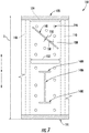
- FIG. 7 an inside view/plane view is provided of a cold side wall 138 from a core cavity 142 of a turbine rotor blade 114 in accordance with still another exemplary embodiment of the present disclosure.
- the turbine rotor blade 114 depicted in FIG. 7 may also be configured in substantially the same manner as exemplary turbine rotor blade 114 described above with reference to FIG. 5 . Accordingly, the same or similar numbering may also refer to the same or similar part.
- the cold side wall 138 also defines a plurality of thermal stress relief slots 148.
- one or more of the stress relief slots 148 defined by the exemplary cold side wall 138 of FIG. 7 do not extend in a direction parallel to the spanwise height S of the rotor blade 114 (i.e. the radial direction R), and instead extend in a direction perpendicular to the spanwise height S of the rotor blade 114.
- the thermal stress relief slots 148 extending in a direction perpendicular to the spanwise height S of the rotor blade 114 extend substantially between adjacent connection walls 140 (depicted in phantom).
- connection walls 140 define a separation distance 156 therebetween, and a length 152 of the thermal stress relief slot 148 extending in a direction perpendicular to the spanwise height S of the rotor blade 114 is substantially equal to the separation distance 156.
- the exemplary embodiment of FIG. 7 additionally includes one or more slanted thermal stress relief slots 148 defining an angle 158 with the direction parallel to the spanwise height S of the rotor blade 114 (i.e., the radial direction R).
- the angle 158 is greater than zero degrees (0°) and less than ninety degrees (90°).
- the slanted thermal stress relief slots 148 define an angle 158 with the direction parallel to the spanwise height S of the rotor blade 114 (i.e., the radial direction R) of about forty-five degrees (45°).
- these slanted thermal stress relief slots 148 defined by the cold side wall 138 also extend substantially between adjacent connection walls 140 (depicted in phantom).
- the exemplary embodiment of FIG. 7 additionally includes one or more thermal stress relief slots 148 having stress relief slots 148 defined integrally at one or both terminating ends.
- the embodiment of FIG. 7 includes a first stress relief slot 148A extending in a direction parallel to the spanwise height S, with a second stress relief slot 148B defined integrally at a first terminal end and a third stress relief slot 148C defined integrally at a second terminal end.
- the slots 148B, 148C at the terminal ends may be orthogonal to the first stress relief slot 148A. Such a configuration may minimize a risk of the slots 148 generating and propagating cracks in the cold side wall 138.
- a component for a gas turbine engine including a cold side wall defining a thermal stress relief slot in accordance with one or more embodiments of the present disclosure may allow for a component to include less thermal stress during operation of the gas turbine engine. More particularly, a component for a gas turbine engine including a cold side wall defining a thermal stress relief slot in accordance with one or more embodiments of the present disclosure may allow for the component to include the double walled configuration as is desirable in certain components, without necessarily including increased thermal stress within the component due to the inevitable temperature differentials between the cold side wall and a hot side sidewall.
- the various exemplary thermal stress relief slots 148 defined by the cold side walls 138 described above with reference to FIGS. 4 through 7 are provided by way of example only.
- the thermal stress relief slots 148 defined by the cold side wall 138 may have any other suitable shape, size, or configuration for providing a thermal stress relief for the component.
- the thermal stress relief slots 148 may define a zig-zag shape, a curved shape, or any other suitable shape.
- the slots 148 may define an angle through a thickness (i.e., in a direction from the core air cavity 142 to the cooling air cavity 144, as shown in FIG. 4 ).
- the component including a cold side wall 138 configured in accordance with one or more embodiments described herein may instead be any other component for a gas turbine engine having a double-walled configuration.
- the component may be a nozzle section of a nozzle stage in a turbine section of the gas turbine engine.
- the component may be a nozzle of the nozzle section and/or an end wall of the nozzle section (e.g., nozzle 100, and endwalls 102, 104).
- the component may be a shroud for the gas turbine engine (e.g., shroud 113), or may be a component of the combustor.
- the cold side wall 138 of the component may be formed using an additive manufacturing process (also known as rapid prototyping, rapid manufacturing, and 3D printing).
- the cold side wall 138 of the component (defining the thermal stress relief slot 148) may be formed using selective laser sintering (SLS), direct metal laser sintering (DMLS), electron beam melting (EBM), diffusion bonding, or selective heat sintering (SHS).
- SLS selective laser sintering
- DMLS direct metal laser sintering
- EBM electron beam melting
- SHS selective heat sintering
- the connection walls 140 may also be formed integrally with the cold side wall 138 using an additive manufacturing process.
- the hot side wall 136 may also be formed integrally with the connection walls 140 and cold side wall 138 using an additive manufacturing process.
- a component formed in accordance with one or more these embodiments may allow for the cold side wall 138 to define the relatively fine details described herein.
- the gas turbine engine may be configured in substantially the same manner as the exemplary turbofan engine 12 described above with reference to FIG. 1 . Accordingly, the exemplary gas turbine engine may define in part a core air flowpath.
- the exemplary method (200) includes at (202) forming a hot side wall to be exposed to the core air flowpath. Additionally, the exemplary method (200) includes at (204) forming a plurality of connection walls. The plurality of connection walls formed at (204) are rigidly connected to or are formed integrally with the hot side wall formed at (202). Further, the exemplary method (200) of FIG. 8 includes at (206) forming a cold side wall using an additive manufacturing process. The cold side wall formed at (206) is rigidly connected to or is formed integrally with the connection walls formed at (204). The cold side wall is spaced from the hot side wall and defines a cooling air cavity together with the connection walls and the hot side wall. The cold side wall is formed at (206) to define a thermal stress relief slot for at least partially accommodating relative thermal expansion between the hot side wall and the cold side wall.
- connection walls and hot side wall may be formed integrally with the cold side wall using an additive manufacturing process.
- forming the plurality of connection walls at (204) may include forming the plurality of connection walls integrally with the cold side wall formed at (206) using an additive manufacturing process.
- forming the hot side wall at (202) may further include forming the hot side wall integrally with the cold side wall and the connection walls using an additive manufacturing process. Accordingly, in such an embodiment, the entire component may be formed integrally using an additive manufacturing process.
- a component for a gas turbine engine formed in accordance with one or more the exemplary aspects described herein may allow for the component to define the relatively fine details of certain of the exemplary embodiments described herein.
- a component for a gas turbine engine formed in accordance with one or more of the exemplary aspects described herein may include a thermal stress relief slot to relieve a thermal stress within the component due to a relative temperature differential between certain aspects of the component, without substantially altering cooling airflow patterns therethrough.
Landscapes
- Engineering & Computer Science (AREA)
- Mechanical Engineering (AREA)
- General Engineering & Computer Science (AREA)
- Physics & Mathematics (AREA)
- Fluid Mechanics (AREA)
- Turbine Rotor Nozzle Sealing (AREA)
Abstract
A component for a gas turbine engine includes a hot side wall 136, a plurality of connection walls 140, and a cold side wall 138. The hot side wall 136 is exposed to a core air flowpath 37 defined by the gas turbine engine. The cold side wall 138 is spaced from the hot side wall 136 and rigidly connected to the hot side wall 136 through the plurality of connection walls 140. The hot side wall 136, connection walls 140, and cold side wall 138 together define a cooling air cavity 144. The cold side wall 138 defines a thermal stress relief slot 148 for at least partially accommodating a relative thermal expansion between the hot side wall 136 and the cold side wall 138 to reduce an amount of thermal stress within the component during operation of the component.
Description
- The present subject matter relates generally to a double-walled component for a gas turbine engine.
- A gas turbine engine generally includes a fan and a core arranged in flow communication with one another. Additionally, the core of the gas turbine engine general includes, in serial flow order, a compressor section, a combustion section, a turbine section, and an exhaust section. In operation, air is provided from the fan to an inlet of the compressor section where one or more axial compressors progressively compress the air until it reaches the combustion section. Fuel is mixed with the compressed air and burned within the combustion section to provide combustion gases. The combustion gases are routed from the combustion section to the turbine section. The flow of combustion gasses through the turbine section drives the turbine section and is then routed through the exhaust section, e.g., to atmosphere.
- The turbine section typically includes a plurality of sequentially arranged stage(s) of turbine nozzles and turbine rotor blades. In at least certain gas turbine engines, the turbine nozzles and/or turbine rotor blades may be configured as a double-walled airfoil. More particularly, the airfoil may include a first wall exposed to the hot temperatures within a hot gas path of the gas turbine engine, and a second, interior wall spaced apart from the first wall. The second wall is typically rigidly connected to the first wall through one or more connection members.
- During operation, however, a temperature of the first wall may become substantially higher than a temperature of the second wall. Given the temperature differential of the first and second walls, and the rigid connection between the first and second walls, and undesirable amount of thermal stress may be generated within the airfoil. Accordingly, an airfoil or other double-walled component capable of better accommodating a temperature differential between a pair of walls would be useful. Further, an airfoil or other double-walled component capable of accommodating a relative thermal expansion between a pair of walls to minimize an amount of thermal stress generated within the component would be particularly beneficial.
- Various aspects and advantages of the invention will be set forth in part in the following description, or may be clear from the description, or may be learned through practice of the invention.
- In one exemplary embodiment of the present disclosure, a component for a turbomachine is provided. The turbomachine defines in part a core air flowpath. The component includes a hot side wall exposed to the core air flowpath, and a plurality of connection walls. The component additionally includes a cold side wall spaced from the hot side wall and rigidly connected to the hot side wall through the plurality of connection walls. The hot side wall, connection walls, and cold side wall together define a cooling air cavity. The cold side wall defines a thermal stress relief slot for at least partially accommodating a relative thermal expansion between the hot side wall and the cold side wall.
- In an exemplary aspect of the present disclosure, a method for manufacturing a component for a gas turbine engine is provided. The gas turbine engine defines in part a core air flowpath. The method includes forming a hot side wall to be exposed to the core air flowpath, and forming a plurality of connection walls. The plurality of connection walls are rigidly connected to or formed integrally with the hot side wall. The method also includes forming a cold side wall using an additive manufacturing process. The cold side wall is rigidly connected to or formed integrally with the connection walls. The cold side wall is spaced from the hot side wall and defines a cooling air cavity together with the connection walls and hot side wall. The cold side wall is formed to define a thermal stress relief slot for at least partially accommodating a relative thermal expansion between the hot side wall and the cold side wall.
- In another exemplary embodiment of the present disclosure, a turbomachine is provided. The turbomachine includes a a turbine section defining in part a core air flowpath. The turbomachine also includes a component. The component includes a hot side wall exposed to the core air flowpath, and a plurality of connection walls. The component additionally includes a cold side wall spaced from the hot side wall and rigidly connected to the hot side wall through the plurality of connection walls. The hot side wall, connection walls, and cold side wall together define a cooling air cavity. The cold side wall defines a thermal stress relief slot for at least partially accommodating a relative thermal expansion between the hot side wall and the cold side wall.
- Various features, aspects and advantages of the present invention will become better understood with reference to the following description and appended claims. The accompanying drawings, which are incorporated in and constitute a part of this specification, illustrate embodiments of the invention and, together with the description, serve to explain the principles of the invention.
- In the drawings:
-
FIG. 1 is a schematic cross-sectional view of an exemplary gas turbine engine according to various embodiments of the present subject matter. -
FIG. 2 is a close-up, side view of a combustion section and a turbine section of the exemplary gas turbine engine ofFIG. 1 . -
FIG. 3 is a perspective view of a rotor blade section in accordance with an exemplary embodiment of the present disclosure, the exemplary rotor blade section being configured for a rotor blade stage of the exemplary gas turbine engine ofFIG. 1 . -
FIG. 4 is a top, cross-sectional view of the exemplary rotor blade section ofFIG. 3 . -
FIG. 5 is a plane view of a cold side wall of the rotor blade section ofFIG. 3 , from an interior portion of the exemplary rotor blade section. -
FIG. 6 is a plane view of a cold side wall of a rotor blade section in accordance with another exemplary embodiment of the present disclosure, from an interior portion of the exemplary rotor blade section. -
FIG. 7 is a plane view of a cold side wall of a rotor blade section in accordance with yet another exemplary embodiment of the present disclosure from an interior portion of the exemplary rotor blade section. -
FIG 8 is a flow diagram of a method for manufacturing a component for a gas turbine engine. - Reference will now be made in detail to present embodiments of the invention, one or more examples of which are illustrated in the accompanying drawings. The detailed description uses numerical and letter designations to refer to features in the drawings. Like or similar designations in the drawings and description have been used to refer to like or similar parts of the invention. As used herein, the terms "first", "second", and "third" may be used interchangeably to distinguish one component from another and are not intended to signify location or importance of the individual components. The terms "upstream" and "downstream" refer to the relative direction with respect to fluid flow in a fluid pathway. For example, "upstream" refers to the direction from which the fluid flows, and "downstream" refers to the direction to which the fluid flows.
- Referring now to the drawings, wherein identical numerals indicate the same elements throughout the figures,
FIG. 1 is a schematic cross-sectional view of a turbomachine in accordance with an exemplary embodiment of the present disclosure. More particularly, for the embodiment ofFIG. 1 , the turbomachine is configured as a gas turbine engine, or rather as a high-bypassturbofan jet engine 12, referred to herein as "turbofan engine 12." As shown inFIG. 1 , theturbofan engine 12 defines an axial direction A (extending parallel to alongitudinal centerline 13 provided for reference), a radial direction R, and a circumferential direction (not shown) extending about the axial direction A. In general, theturbofan 12 includes afan section 14 and acore turbine engine 16 disposed downstream from thefan section 14. - The exemplary
core turbine engine 16 depicted generally includes a substantially tubularouter casing 18 that defines anannular inlet 20. Theouter casing 18 encases and thecore turbine engine 16 includes, in serial flow relationship, a compressor section including a booster or low pressure (LP)compressor 22 and a high pressure (HP)compressor 24; acombustion section 26; a turbine section including a high pressure (HP)turbine 28 and a low pressure (LP)turbine 30; and a jetexhaust nozzle section 32. A high pressure (HP) shaft orspool 34 drivingly connects the HPturbine 28 to the HPcompressor 24. A low pressure (LP) shaft orspool 36 drivingly connects theLP turbine 30 to theLP compressor 22. Accordingly, theLP shaft 36 and HPshaft 34 are each rotary components, rotating about the axial direction A during operation of theturbofan engine 12. - Referring still to the embodiment of
FIG. 1 , thefan section 14 includes avariable pitch fan 38 having a plurality offan blades 40 coupled to adisk 42 in a spaced apart manner. As depicted, thefan blades 40 extend outwardly fromdisk 42 generally along the radial direction R. Eachfan blade 40 is rotatable relative to thedisk 42 about a pitch axis P by virtue of thefan blades 40 being operatively coupled to a suitablepitch change mechanism 44 configured to collectively vary the pitch of thefan blades 40 in unison. Thefan blades 40,disk 42, andpitch change mechanism 44 are together rotatable about thelongitudinal axis 12 byLP shaft 36 across apower gear box 46. Thepower gear box 46 includes a plurality of gears for adjusting the rotational speed of thefan 38 relative to theLP shaft 36 to a more efficient rotational fan speed. More particularly, the fan section includes a fan shaft rotatable by theLP shaft 36 across thepower gearbox 46. Accordingly, the fan shaft may also be considered a rotary component, and is similarly supported by one or more bearings. - Referring still to the exemplary embodiment of
FIG. 1 , thedisk 42 is covered by arotatable front hub 48 aerodynamically contoured to promote an airflow through the plurality offan blades 40. Additionally, theexemplary fan section 14 includes an annular fan casing orouter nacelle 50 that circumferentially surrounds thefan 38 and/or at least a portion of thecore turbine engine 16. Theexemplary nacelle 50 is supported relative to thecore turbine engine 16 by a plurality of circumferentially-spaced outlet guide vanes 52. Moreover, adownstream section 54 of thenacelle 50 extends over an outer portion of thecore turbine engine 16 so as to define abypass airflow passage 56 therebetween. - During operation of the
turbofan engine 12, a volume ofair 58 enters theturbofan 12 through an associatedinlet 60 of thenacelle 50 and/orfan section 14. As the volume ofair 58 passes across thefan blades 40, a first portion of theair 58 as indicated byarrows 62 is directed or routed into thebypass airflow passage 56 and a second portion of theair 58 as indicated byarrow 64 is directed or routed into thecore air flowpath 37, or more specifically into theLP compressor 22. The ratio between the first portion ofair 62 and the second portion ofair 64 is commonly known as a bypass ratio. The pressure of the second portion ofair 64 is then increased as it is routed through the high pressure (HP)compressor 24 and into thecombustion section 26, where it is mixed with fuel and burned to provide combustion gases 66. - The combustion gases 66 are routed through the
HP turbine 28 where a portion of thermal and/or kinetic energy from the combustion gases 66 is extracted via sequential stages of HP turbine stator vanes 68 that are coupled to theouter casing 18 and HPturbine rotor blades 70 that are coupled to the HP shaft orspool 34, thus causing the HP shaft orspool 34 to rotate, thereby supporting operation of theHP compressor 24. The combustion gases 66 are then routed through theLP turbine 30 where a second portion of thermal and kinetic energy is extracted from the combustion gases 66 via sequential stages of LPturbine stator vanes 72 that are coupled to theouter casing 18 and LPturbine rotor blades 74 that are coupled to the LP shaft orspool 36, thus causing the LP shaft orspool 36 to rotate, thereby supporting operation of theLP compressor 22 and/or rotation of thefan 38. - The combustion gases 66 are subsequently routed through the jet
exhaust nozzle section 32 of thecore turbine engine 16 to provide propulsive thrust. Simultaneously, the pressure of the first portion ofair 62 is substantially increased as the first portion ofair 62 is routed through thebypass airflow passage 56 before it is exhausted from a fannozzle exhaust section 76 of theturbofan 12, also providing propulsive thrust. TheHP turbine 28, theLP turbine 30, and the jetexhaust nozzle section 32 at least partially define ahot gas path 78 for routing the combustion gases 66 through thecore turbine engine 16. - It should be appreciated, however, that the
exemplary turbofan engine 12 depicted inFIG. 1 is provided by way of example only, and that in other exemplary embodiments, theturbofan engine 12 may have any other suitable configuration. It should also be appreciated, that in still other exemplary embodiments, aspects of the present disclosure may be incorporated into any other suitable gas turbine engine. For example, in other exemplary embodiments, aspects of the present disclosure may be incorporated into, e.g., a turboprop engine, a turboshaft engine, or a turbojet engine. Further, in still other embodiments, aspects of the present disclosure may be incorporated into any other suitable turbomachine, including, without limitation, a steam turbine, a centrifugal compressor, and/or a turbocharger. - Referring now to
FIG. 2 , a close-up, cross-sectional view is provided of theturbofan engine 12 ofFIG. 1 , and particularly of thecombustion section 26 and theHP turbine 28 of the turbine section. Thecombustion section 26 depicted generally includes acombustor 79 having acombustion chamber 80 defined by aninner liner 82 and anouter liner 84, thecombustion chamber 80 extending generally along the axial direction A from aforward end 86 to anaft end 88. A plurality offuel nozzles 90 are positioned at theforward end 86 of thecombustion chamber 80 for providing thecombustion chamber 80 with a mixture of fuel and compressed air from the compressor section. As discussed above, the fuel and air mixture is combusted within thecombustion chamber 80 to generate a flow of combustion gasses therethrough. - Downstream of the
combustion section 26, theHP turbine 28 includes a plurality of turbine component stages, each turbine component stage comprising a plurality of turbine component sections. More particularly, for the embodiment depicted, theHP turbine 28 includes a plurality of turbine nozzle stages, as well as one or more stages of turbine rotor blades. Specifically, for the embodiment depicted, theHP turbine 28 includes a firstturbine nozzle stage 92 and a secondturbine nozzle stage 94, each configured to direct a flow of combustion gasses therethrough. The firstturbine nozzle stage 92 includes a plurality ofturbine nozzle sections 96 spaced along a circumferential direction C (a direction extending about the axial direction A; seeFIG. 3 ). Notably, the firstturbine nozzle stage 92 is located immediately downstream from thecombustion section 26, and thus may also be referred to as a combustor discharge nozzle stage having a plurality of combustion discharge nozzle sections. Additionally, for the exemplary embodiment depicted, the secondturbine nozzle stage 94 also includes a plurality of turbine nozzle sections 98 spaced along the circumferential direction C. - Each of the
turbine nozzle sections 96, 98 forming the first and second turbine nozzle stages 92, 94 includes aturbine nozzle 100 positioned within thecore air flowpath 37, exposed to and at least partially defining thecore air flowpath 37. Theturbine nozzle 100 is configured as an airfoil. Theturbine nozzle sections 96, 98, also include an endwall, or more particularly, aninner endwall 102 and anouter endwall 104. Thenozzle 100 extends generally along the radial direction R from theinner endwall 102 to theouter endwall 104. Theturbine nozzle 100,inner endwall 102, andouter endwall 104 each include aflowpath surface 106 at least partially exposed to thecore air flowpath 37. - Located immediately downstream of the first
turbine nozzle stage 92 and immediately upstream of the secondturbine nozzle stage 94, theHP turbine 28 includes a first turbinerotor blade stage 108. The first turbinerotor blade stage 108 includes a plurality of turbinerotor blade sections 110 spaced along the circumferential direction C and a firststage rotor disk 112. The plurality of turbinerotor blade sections 110 are attached to the firststage rotor disk 112, and although not depicted, theturbine rotor disk 112 is, in turn, connected to the HP shaft 34 (seeFIG. 1 ). Theturbofan engine 12 additionally includes ashroud 113 exposed to and at least partially defining thecore air flowpath 37. Theshroud 113 is configured to form a seal with the first turbinerotor blade stage 108. - Referring now also to
FIG. 3 , providing a perspective view of one of the plurality of turbinerotor blade sections 110, each of the plurality of turbinerotor blade sections 110 includes aturbine rotor blade 114, a wall orplatform 116, and abase 118. Therotor blade 114 is also configured as an airfoil, and extends outwardly along a spanwise direction (or rather, along the radial direction R when installed) to define a spanwise height S. Specifically, therotor blade 114 extends along the radial direction R from a radiallyinner end 115 at theplatform 116 to atip 120 of therotor blade 114. - As will be appreciated, the
tip 120 of therotor blade 114 is configured to form a seal with the shroud 113 (seeFIG. 2 ). - Additionally, the
turbine rotor blade 114 defines aleading edge 122 and anopposite trailing edge 124, as well as apressure side 126 and anopposite suction side 128. During operation, hot combustion gases are generated in the combustion section and flow in a downstream direction D (seeFIG. 2 ) over theturbine rotor blades 114, theturbine rotor blades 114 extracting energy therefrom for rotating therotor disk 112 supporting therotor blades 114, which may in turn rotate theHP shaft 34. - As is also depicted, the
turbine rotor blade 114 additionally includes one or more thermal management features, or more particular, includes a plurality of cooling holes 130. For theexemplary rotor blade 114 depicted, therotor blade 114 defines a plurality ofcooling holes 130 extending along the spanwise height S of therotor blade 114 at theleading edge 122, a plurality ofcooling holes 130 extending along the spanwise height S of therotor blade 114 at the trailingedge 122, and a plurality ofother cooling holes 130 extending along the spanwise height S on thepressure side 126. Although not depicted, therotor blade 114 may also include a plurality ofcooling holes 130 extending along the spanwise height S of therotor blade 114 on thesuction side 128. - Referring now also to
FIG. 4 , providing a cross-sectional view of the exemplaryturbine rotor blade 114 ofFIG. 3 , theturbine rotor blade 114 is configured as a double-walled airfoil. More particularly, theturbine rotor blade 114 generally includes abody section 132 and a trailingedge section 134. Thebody section 132 of theturbine rotor blade 114 is formed of two substantially parallel walls. For example, the exemplaryturbine rotor blade 114 depicted includes ahot side wall 136 exposed to the core air flowpath and acold side wall 138 spaced from thehot side wall 136 and positioned within theturbine rotor blade 114. Therotor blade 114 additionally includes a plurality ofconnection walls 140, with thecold side wall 138 rigidly connected to thehot side wall 136 through the plurality ofconnection walls 140. - As is also depicted, the exemplary
turbine rotor blade 114 defines acore cavity 142 and a plurality of coolingair cavities 144. Thehot side wall 136,connection walls 140, andcold side wall 138 together define the plurality of coolingair cavities 144. - Referring now to
FIG. 5 , an inside view of a section of therotor blade 114 ofFIG. 4 is provided, taken along Line 5-5 ofFIG. 4 . More particularly,FIG. 5 provides a plane view of thecold side wall 138 from thecore cavity 142 of theturbine rotor blade 114, from the radiallyinner end 115 where therotor blade 114 is attached to theplatform 116 to thetip 120 of therotor blade 114. - As is depicted, the exemplary
cold side wall 138 depicted additionally includes a plurality of impingement holes 146 to allow a cooling airflow from thecore cavity 142 into the coolingair cavity 144. Although not depicted, in certain embodiments, the cooling airflow may be provided to the coolingair cavities 144 additionally, or alternatively, from around an end of thecold side wall 138, such as through a root or from a tip of thecold side wall 138. Accordingly, in certain embodiments, thecold side wall 138 may not include the impingement holes 146. Regardless, during operation of theturbofan engine 12, a cooling airflow may be provided through, e.g., thebase 118 of the rotor blade section 110 (seeFIG. 3 ), to thecore cavity 142, and from thecore cavity 142 to one or more of the coolingair cavities 144. As discussed above, thehot side wall 136 additionally defines the plurality of cooling holes 130. The plurality ofcooling holes 130 defined by thehot side wall 136 may be configured for allowing the cooling airflow from the coolingair cavity 144 to flow through thehot side wall 136 to provide a cooling film along an exterior surface of therotor blade 114. - As will be appreciated, during operation of the
turbofan engine 12, thehot side wall 136 will be exposed to the relatively high temperatures within the core air flowpath. By contrast, thecold side wall 138 will be exposed on one side to thecore cavity 142 and on the other side to the coolingair cavity 144. Accordingly, during operation a temperature of thecold side wall 138 may be substantially less than a temperature of thehot side wall 136. Moreover, the inventor of the present disclosure has discovered that as thecold side wall 138 is rigidly connected to thehot side wall 136 through thevarious connection walls 140, a temperature differential between thecold side wall 138 andhot side wall 136 may cause an undesirable amount of thermal stress in one or both of thehot side wall 136 or thecold side wall 138. In order to relieve at least some of such thermal stress, thecold side wall 138 defines a thermalstress relief slot 148. Inclusion of thestress relief slot 148 allows thecold side wall 138 to at least partially accommodate relative thermal expansion between thehot side wall 136 andcold side wall 138 with less thermal stress in the components. - For the embodiment of
FIG. 5 , thehot side wall 136 extends along the entire spanwise height S of therotor blade 114 and thecold side wall 138 extends at least substantially along the entire spanwise height S of therotor blade 114. For example, thehot side wall 136 extends from the radiallyinner end 115 of therotor blade 114 to thetip 120 of therotor blade 114, and thecold side wall 138 extends from the radiallyinner end 115 of therotor blade 114 substantially to thetip 120 of therotor blade 114. It should be appreciated, however, that in other embodiments, the cold side wall 138 (and cooling air cavity 144) may not extend entirely from the radiallyinner end 115 to thetip 120 of therotor blade 114. - For the embodiment depicted, the thermal
stress relief slot 148 defined by thecold side wall 138 also extends in a direction parallel to the spanwise height S of the rotor blade 114 (i.e., along the spanwise direction/ radial direction R). Additionally, for the embodiment depicted the thermalstress relief slot 148 extends continuously and substantially along an entirety of the spanwise height S of therotor blade 114. More particularly, for the embodiment depicted, the thermalstress relief slot 148 defines alength 152, thelength 152 being substantially equal to the spanwise height S of therotor blade 114. It should be appreciated, that as used herein, terms of approximation, such as "about" or "substantially," refers to being within a 10% margin of error. - Furthermore, as is also depicted in
FIG. 5 , each of theconnection walls 140 also extend in a direction parallel to the spanwise height S of the rotor blade 114 (i.e., along the spanwise direction/ radial direction R). Additionally, for the embodiment depicted, the thermalstress relief slot 148 is defined by thecold side wall 138 at a location substantially equidistant between twoadjacent connection walls 140. - As previously discussed, the
cold side wall 138 additionally defines a plurality of impingement holes 146 for providing an airflow communication between thecore cavity 142 and the coolingair cavities 144. Although the impingement holes 146 provide an opening through thecold side wall 138, the impingement holes 146 do not provide a meaningful thermal stress relief. Additionally, although the thermalstress relief slot 148 provides an opening through thecold side wall 138, the thermalstress relief slots 148 do not provide substantial airflow communication between thecore cavity 142 and the coolingair cavity 144. For example, the thermalstress relief slot 148 defines awidth 150 in a direction perpendicular to the direction in which it extends. In certain embodiments, thewidth 150 of the thermalstress relief slot 148 may be less than about one (1) millimeters ("mm"). Preferably, however, thewidth 150 of the thermalstress relief slot 148 may be less than about one-half (0.5) mm, less than about one-fourth (0.25) mm, or less than about one-tenth (0.1) mm. For example, in certain exemplary embodiments, thewidth 150 of thestress release slot 148 may be less than or equal to about 0.025 mm. - Notably, for the embodiment depicted, the thermal
stress relief slot 148 defines a substantiallyconstant width 150 along theentire length 152 of theslot 148. However, in other embodiments, thecold side wall 138 may instead define avariable width 150stress release slot 148 based on an anticipated amount of expansion/thermal stress of the components. - It should also be appreciated, that in other exemplary embodiments, the
cold side wall 138 may define any other suitable thermal stress relief slot(s) 148. For example, referring now toFIG. 6 , an inside view/ plane view is provided of acold side wall 138 from acore cavity 142 of aturbine rotor blade 114 in accordance with another exemplary embodiment of the present disclosure. Theturbine rotor blade 114 depicted inFIG. 6 may be configured in substantially the same manner as exemplaryturbine rotor blade 114 described above with reference toFIG. 5 . Accordingly, the same or similar numbering may refer to same or similar part. - However, for the embodiment of
FIG. 6 , thecold side wall 138 further defines a plurality of thermalstress relief slots 148. Each of the plurality of thermal stress relief slots are aligned and extend in a direction parallel to a spanwise height S of therotor blade 114. Further, the plurality thermalstress relief slots 148 together extend substantially along the entire spanwise height S of therotor blade 114. More particularly, each of the thermalstress relief slots 148 define alength 152, and the sum of thelengths 152 of the aligned thermalstress relief slots 148 is substantially equal to the spanwise height S of therotor blade 114. Accordingly, although there arebreaks 154 between adjacentstress relief slots 148, the plurality thermalstress relief slots 148 may still provide a desired amount of thermal stress relief during operation of theturbofan engine 12. Despite there being a plurality ofstress relief slots 148, thestress release slots 148 depicted may in other respects be configured in the same manner as exemplarystress release slots 148 defined by thecold side wall 138 described above. - Further, in still other exemplary embodiments the present disclosure, the
cold side wall 138 may define any other suitable form ofstress relief slots 148. For example, referring now toFIG. 7 , an inside view/plane view is provided of acold side wall 138 from acore cavity 142 of aturbine rotor blade 114 in accordance with still another exemplary embodiment of the present disclosure. Theturbine rotor blade 114 depicted inFIG. 7 may also be configured in substantially the same manner as exemplaryturbine rotor blade 114 described above with reference toFIG. 5 . Accordingly, the same or similar numbering may also refer to the same or similar part. - For the embodiment of
FIG. 7 , thecold side wall 138 also defines a plurality of thermalstress relief slots 148. However, one or more of thestress relief slots 148 defined by the exemplarycold side wall 138 ofFIG. 7 do not extend in a direction parallel to the spanwise height S of the rotor blade 114 (i.e. the radial direction R), and instead extend in a direction perpendicular to the spanwise height S of therotor blade 114. For the embodiment depicted, the thermalstress relief slots 148 extending in a direction perpendicular to the spanwise height S of therotor blade 114 extend substantially between adjacent connection walls 140 (depicted in phantom). More particularly, for the embodiment depicted, theadjacent connection walls 140 define aseparation distance 156 therebetween, and alength 152 of the thermalstress relief slot 148 extending in a direction perpendicular to the spanwise height S of therotor blade 114 is substantially equal to theseparation distance 156. - Notably, the exemplary embodiment of
FIG. 7 additionally includes one or more slanted thermalstress relief slots 148 defining anangle 158 with the direction parallel to the spanwise height S of the rotor blade 114 (i.e., the radial direction R). Theangle 158 is greater than zero degrees (0°) and less than ninety degrees (90°). Particularly, for the embodiment depicted, the slanted thermalstress relief slots 148 define anangle 158 with the direction parallel to the spanwise height S of the rotor blade 114 (i.e., the radial direction R) of about forty-five degrees (45°). Notably, these slanted thermalstress relief slots 148 defined by thecold side wall 138 also extend substantially between adjacent connection walls 140 (depicted in phantom). - Moreover, the exemplary embodiment of
FIG. 7 additionally includes one or more thermalstress relief slots 148 havingstress relief slots 148 defined integrally at one or both terminating ends. Specifically, the embodiment ofFIG. 7 includes a firststress relief slot 148A extending in a direction parallel to the spanwise height S, with a secondstress relief slot 148B defined integrally at a first terminal end and a thirdstress relief slot 148C defined integrally at a second terminal end. Theslots stress relief slot 148A. Such a configuration may minimize a risk of theslots 148 generating and propagating cracks in thecold side wall 138. - A component for a gas turbine engine including a cold side wall defining a thermal stress relief slot in accordance with one or more embodiments of the present disclosure may allow for a component to include less thermal stress during operation of the gas turbine engine. More particularly, a component for a gas turbine engine including a cold side wall defining a thermal stress relief slot in accordance with one or more embodiments of the present disclosure may allow for the component to include the double walled configuration as is desirable in certain components, without necessarily including increased thermal stress within the component due to the inevitable temperature differentials between the cold side wall and a hot side sidewall.
- It should be appreciated, however, that the various exemplary thermal
stress relief slots 148 defined by thecold side walls 138 described above with reference toFIGS. 4 through 7 are provided by way of example only. In other exemplary embodiments, the thermalstress relief slots 148 defined by thecold side wall 138 may have any other suitable shape, size, or configuration for providing a thermal stress relief for the component. For example, in other embodiments, the thermalstress relief slots 148 may define a zig-zag shape, a curved shape, or any other suitable shape. Additionally, or alternatively, theslots 148 may define an angle through a thickness (i.e., in a direction from thecore air cavity 142 to the coolingair cavity 144, as shown inFIG. 4 ). - Further, in light of the above benefits, it should be appreciated that in still other embodiments, the component including a
cold side wall 138 configured in accordance with one or more embodiments described herein may instead be any other component for a gas turbine engine having a double-walled configuration. For example, in other exemplary embodiments, the component may be a nozzle section of a nozzle stage in a turbine section of the gas turbine engine. For example, the component may be a nozzle of the nozzle section and/or an end wall of the nozzle section (e.g.,nozzle 100, and endwalls 102, 104). Additionally, or alternatively, the component may be a shroud for the gas turbine engine (e.g., shroud 113), or may be a component of the combustor. - Furthermore, as is discussed in greater detail below with reference to the exemplary flow diagram of
FIG. 8 , thecold side wall 138 of the component may be formed using an additive manufacturing process (also known as rapid prototyping, rapid manufacturing, and 3D printing). For example, in certain exemplary aspects, thecold side wall 138 of the component (defining the thermal stress relief slot 148) may be formed using selective laser sintering (SLS), direct metal laser sintering (DMLS), electron beam melting (EBM), diffusion bonding, or selective heat sintering (SHS). Additionally, in certain embodiments, theconnection walls 140 may also be formed integrally with thecold side wall 138 using an additive manufacturing process. Further, in still other embodiments, thehot side wall 136 may also be formed integrally with theconnection walls 140 andcold side wall 138 using an additive manufacturing process. A component formed in accordance with one or more these embodiments may allow for thecold side wall 138 to define the relatively fine details described herein. - Referring now to
FIG. 8 , a flow diagram of a method for manufacturing a component for a gas turbine engine is provided. The gas turbine engine may be configured in substantially the same manner as theexemplary turbofan engine 12 described above with reference toFIG. 1 . Accordingly, the exemplary gas turbine engine may define in part a core air flowpath. - As depicted, the exemplary method (200) includes at (202) forming a hot side wall to be exposed to the core air flowpath. Additionally, the exemplary method (200) includes at (204) forming a plurality of connection walls. The plurality of connection walls formed at (204) are rigidly connected to or are formed integrally with the hot side wall formed at (202). Further, the exemplary method (200) of
FIG. 8 includes at (206) forming a cold side wall using an additive manufacturing process. The cold side wall formed at (206) is rigidly connected to or is formed integrally with the connection walls formed at (204). The cold side wall is spaced from the hot side wall and defines a cooling air cavity together with the connection walls and the hot side wall. The cold side wall is formed at (206) to define a thermal stress relief slot for at least partially accommodating relative thermal expansion between the hot side wall and the cold side wall. - Notably, in certain exemplary aspects, one or more of the connection walls and hot side wall may be formed integrally with the cold side wall using an additive manufacturing process. For example, in certain exemplary aspects, forming the plurality of connection walls at (204) may include forming the plurality of connection walls integrally with the cold side wall formed at (206) using an additive manufacturing process. Additionally, in certain exemplary aspects, forming the hot side wall at (202) may further include forming the hot side wall integrally with the cold side wall and the connection walls using an additive manufacturing process. Accordingly, in such an embodiment, the entire component may be formed integrally using an additive manufacturing process.
- A component for a gas turbine engine formed in accordance with one or more the exemplary aspects described herein may allow for the component to define the relatively fine details of certain of the exemplary embodiments described herein. For example, a component for a gas turbine engine formed in accordance with one or more of the exemplary aspects described herein may include a thermal stress relief slot to relieve a thermal stress within the component due to a relative temperature differential between certain aspects of the component, without substantially altering cooling airflow patterns therethrough.
- This written description uses examples to disclose the invention, including the preferred mode, and also to enable any person skilled in the art to practice the invention, including making and using any devices or systems and performing any incorporated methods. The patentable scope of the invention is defined by the claims, and may include other examples that occur to those skilled in the art. Such other examples are intended to be within the scope of the claims if they include structural elements that do not differ from the literal language of the claims, or if they include equivalent structural elements with insubstantial differences from the literal languages of the claims.
- Various aspects and embodiments of the present invention are defined by the following numbered clauses:
- 1. A component for a turbomachine, the turbomachine defining in part a core air flowpath, the component comprising:
- a hot side wall exposed to the core air flowpath when installed in the gas turbine engine;
- a plurality of connection walls; and
- a cold side wall spaced from the hot side wall and rigidly connected to the hot side wall through the plurality of connection walls, the hot side wall, connection walls, and cold side wall together defining a cooling air cavity, the cold side wall defining a thermal stress relief slot for at least partially accommodating a relative thermal expansion between the hot side wall and the cold side wall.
- 2. The component of clause 1, wherein the component is an airfoil for a turbine section of the gas turbine engine.
- 3. The component of any preceding clause, wherein the airfoil defines a spanwise direction, wherein the hot side wall and the cold side wall each extend along the spanwise direction of the airfoil, and wherein the thermal stress relief slot also extends along the spanwise direction of the airfoil.
- 4. The component of any preceding clause, wherein the plurality of connection walls extend along the spanwise direction, wherein the thermal stress relief slot defined by the cold side wall is defined at a location substantially equidistant between two adjacent connection walls.
- 5. The component of any preceding clause, wherein the airfoil defines a spanwise direction, wherein the hot side wall and the cold side wall each extend along the spanwise direction of the airfoil, and wherein the thermal stress relief slot extends in a direction perpendicular to the spanwise direction of the airfoil.
- 6. The component of any preceding clause, wherein the airfoil defines a spanwise height, wherein the cold side wall extends substantially along an entirety of the spanwise height, and wherein the thermal stress relief slot also extends substantially along an entirety of the spanwise height.
- 7. The component of any preceding clause, wherein the cold side wall further defines a plurality of thermal stress relief slots, wherein the airfoil defines a spanwise height, wherein the cold side wall extends substantially along an entirety of the spanwise height, and wherein the plurality of thermal stress relief slots together extend substantially along an entirety of the spanwise height.
- 8. The component of any preceding clause, wherein the hot side wall defines a plurality of cooling holes for allowing a cooling airflow from the cooling air cavity through the hot side wall.
- 9. The component of any preceding clause, wherein the cold side wall further defines a plurality of impingement holes to allow a cooling airflow into the cooling air cavity.
- 10. The component of any preceding clause, wherein the component is a nozzle section of a nozzle stage for the gas turbine engine, and wherein the hot side wall and cold side wall form an endwall of the nozzle section.
- 11. The component of any preceding clause, wherein the component is a shroud for the gas turbine engine.
- 12. The component of any preceding clause, wherein the cold side wall is formed using an additive manufacturing process.
- 13. The component of any preceding clause, wherein the cold side wall further defines a plurality of thermal stress relief slots.
- 14. The component of any preceding clause, wherein the thermal stress relief slot defines a width, and wherein the width is less than about one millimeter.
- 15. The component of any preceding clause, wherein the thermal stress relief slot defines a width, and wherein the width is less than or equal to about 0.025 millimeters.
- 16. A method for manufacturing a component for a gas turbine engine, the gas turbine engine defining in part a core air flowpath, the method comprising:
- forming a hot side wall to be exposed to the core air flowpath;
- forming a plurality of connection walls, the plurality of connection walls rigidly connected to or formed integrally with the hot side wall; and
- forming a cold side wall, the cold side wall rigidly connected to or formed integrally with the connection walls, the cold side wall spaced from the hot side wall and defining a cooling air cavity together with the connection walls and hot side wall, the cold side wall formed to define a thermal stress relief slot for at least partially accommodating a relative thermal expansion between the hot side wall and the cold side wall.
- 17. The method of any preceding clause, wherein forming the cold side wall comprises forming the cold side wall using an additive manufacturing process.
- 18. The method of any preceding clause, wherein forming the plurality of connection walls comprises forming the plurality of connection walls integrally with the cold side wall using an additive manufacturing process.
- 19. The method of any preceding clause, wherein forming the hot side wall comprises forming the hot side wall integrally with the cold side wall and connection walls using an additive manufacturing process.
- 20. A turbomachine comprising:
- a turbine section defining in part a core air flowpath; and
- a component comprising
- a hot side wall exposed to the core air flowpath;
- a plurality of connection walls; and
- a cold side wall spaced from the hot side wall and rigidly connected to the hot side wall through the plurality of connection walls, the hot side wall, connection walls, and cold side wall together defining a cooling air cavity, the cold side wall defining a thermal stress relief slot for at least partially accommodating a relative thermal expansion between the hot side wall and the cold side wall.
Claims (10)
- A component for a turbomachine, the turbomachine defining in part a core air flowpath (37), the component comprising:a hot side wall (136) exposed to the core air flowpath (37) when installed in the gas turbine engine;a plurality of connection walls (140); anda cold side wall (138) spaced from the hot side wall (136) and rigidly connected to the hot side wall (136) through the plurality of connection walls (140), the hot side wall (136), connection walls (140), and cold side wall (138) together defining a cooling air cavity (144), the cold side wall (138) defining a thermal stress relief slot (148) for at least partially accommodating a relative thermal expansion between the hot side wall (136) and the cold side wall (138).
- The component of claim 1, wherein the component is an airfoil for a turbine section of the gas turbine engine.
- The component of claim 2, wherein the airfoil defines a spanwise direction, wherein the hot side wall (136) and the cold side wall (138) each extend along the spanwise direction of the airfoil, and wherein the thermal stress relief slot (148) also extends along the spanwise direction of the airfoil.
- The component of claim 2 or claim 3, wherein the airfoil defines a spanwise height S, wherein the cold side wall (138) extends substantially along an entirety of the spanwise height S, and wherein the thermal stress relief slot (148) also extends substantially along an entirety of the spanwise height S.
- The component of any preceding claim, wherein the component is a nozzle section of a nozzle stage for the gas turbine engine, and wherein the hot side wall (136) and cold side wall (138) form an endwall of the nozzle section.
- The component of any preceding claim, wherein the cold side wall (138) is formed using an additive manufacturing process.
- The component of any preceding claim, wherein the thermal stress relief slot (148) defines a width (150), and wherein the width is less than about one millimeter.
- A method for manufacturing a component for a gas turbine engine, the gas turbine engine defining in part a core air flowpath, the method comprising:forming at (202) a hot side wall to be exposed to the core air flowpath;forming at (204) a plurality of connection walls, the plurality of connection walls rigidly connected to or formed integrally with the hot side wall; andforming at (206) a cold side wall, the cold side wall rigidly connected to or formed integrally with the connection walls, the cold side wall spaced from the hot side wall and defining a cooling air cavity together with the connection walls and hot side wall, the cold side wall formed to define a thermal stress relief slot for at least partially accommodating a relative thermal expansion between the hot side wall and the cold side wall.
- The method of claim 8, wherein forming the cold side wall at (206) comprises forming the cold side wall using an additive manufacturing process.
- The method of claim 9, wherein forming the hot side wall at (202) comprises forming the hot side wall integrally with the cold side wall and connection walls using an additive manufacturing process.
Applications Claiming Priority (1)
| Application Number | Priority Date | Filing Date | Title |
|---|---|---|---|
| US15/042,674 US10415408B2 (en) | 2016-02-12 | 2016-02-12 | Thermal stress relief of a component |
Publications (1)
| Publication Number | Publication Date |
|---|---|
| EP3205823A1 true EP3205823A1 (en) | 2017-08-16 |
Family
ID=58016627
Family Applications (1)
| Application Number | Title | Priority Date | Filing Date |
|---|---|---|---|
| EP17155626.9A Withdrawn EP3205823A1 (en) | 2016-02-12 | 2017-02-10 | Thermal stress relief of a component |
Country Status (5)
| Country | Link |
|---|---|
| US (1) | US10415408B2 (en) |
| EP (1) | EP3205823A1 (en) |
| JP (1) | JP2017141823A (en) |
| CN (1) | CN107084002B (en) |
| CA (1) | CA2956978A1 (en) |
Families Citing this family (3)
| Publication number | Priority date | Publication date | Assignee | Title |
|---|---|---|---|---|
| US10801351B2 (en) * | 2018-04-17 | 2020-10-13 | Raytheon Technologies Corporation | Seal assembly for gas turbine engine |
| US10845132B2 (en) | 2018-11-05 | 2020-11-24 | Hamilton Sundstrand Corporation | Additively manufactured fin slots for thermal growth |
| CN114420314A (en) * | 2021-12-20 | 2022-04-29 | 核工业西南物理研究院 | First wall structure for high-dose neutron irradiation and megawatt-scale heat loads in fusion reactors |
Citations (4)
| Publication number | Priority date | Publication date | Assignee | Title |
|---|---|---|---|---|
| US5702232A (en) * | 1994-12-13 | 1997-12-30 | United Technologies Corporation | Cooled airfoils for a gas turbine engine |
| US7527474B1 (en) * | 2006-08-11 | 2009-05-05 | Florida Turbine Technologies, Inc. | Turbine airfoil with mini-serpentine cooling passages |
| US20110236221A1 (en) * | 2010-03-26 | 2011-09-29 | Campbell Christian X | Four-Wall Turbine Airfoil with Thermal Strain Control for Reduced Cycle Fatigue |
| US20120269648A1 (en) * | 2011-04-22 | 2012-10-25 | Ching-Pang Lee | Serpentine cooling circuit with t-shaped partitions in a turbine airfoil |
Family Cites Families (14)
| Publication number | Priority date | Publication date | Assignee | Title |
|---|---|---|---|---|
| DE50306044D1 (en) * | 2003-09-05 | 2007-02-01 | Siemens Ag | Shovel of a turbine |
| US6981840B2 (en) * | 2003-10-24 | 2006-01-03 | General Electric Company | Converging pin cooled airfoil |
| EP2412101A1 (en) * | 2009-03-27 | 2012-02-01 | Nokia Corp. | System and method for signaling of interfering spatial layers with dedicated reference signal |
| US8147196B2 (en) * | 2009-05-05 | 2012-04-03 | Siemens Energy, Inc. | Turbine airfoil with a compliant outer wall |
| US8638596B2 (en) * | 2011-07-25 | 2014-01-28 | Qualcomm Incorporated | Non-volatile memory saving cell information in a non-volatile memory array |
| WO2013037387A1 (en) | 2011-09-16 | 2013-03-21 | Stryker Trauma Gmbh | Polyaxial locking hole arrangement |
| US9121286B2 (en) | 2012-04-24 | 2015-09-01 | United Technologies Corporation | Airfoil having tapered buttress |
| US9296039B2 (en) | 2012-04-24 | 2016-03-29 | United Technologies Corporation | Gas turbine engine airfoil impingement cooling |
| US10755292B2 (en) * | 2012-07-06 | 2020-08-25 | Oracle International Corporation | Service design and order fulfillment system with service order |
| US9289826B2 (en) | 2012-09-17 | 2016-03-22 | Honeywell International Inc. | Turbine stator airfoil assemblies and methods for their manufacture |
| EP2900964A4 (en) | 2012-09-28 | 2016-06-29 | United Technologies Corp | Uber-cooled turbine section component made by additive manufacturing |
| US20140216042A1 (en) | 2012-09-28 | 2014-08-07 | United Technologies Corporation | Combustor component with cooling holes formed by additive manufacturing |
| US20140126995A1 (en) * | 2012-11-06 | 2014-05-08 | General Electric Company | Microchannel cooled turbine component and method of forming a microchannel cooled turbine component |
| EP2863010A1 (en) * | 2013-10-21 | 2015-04-22 | Siemens Aktiengesellschaft | Turbine blade |
-
2016
- 2016-02-12 US US15/042,674 patent/US10415408B2/en active Active
-
2017
- 2017-01-27 JP JP2017012601A patent/JP2017141823A/en active Pending
- 2017-02-02 CA CA2956978A patent/CA2956978A1/en not_active Abandoned
- 2017-02-10 EP EP17155626.9A patent/EP3205823A1/en not_active Withdrawn
- 2017-02-10 CN CN201710075031.7A patent/CN107084002B/en active Active
Patent Citations (4)
| Publication number | Priority date | Publication date | Assignee | Title |
|---|---|---|---|---|
| US5702232A (en) * | 1994-12-13 | 1997-12-30 | United Technologies Corporation | Cooled airfoils for a gas turbine engine |
| US7527474B1 (en) * | 2006-08-11 | 2009-05-05 | Florida Turbine Technologies, Inc. | Turbine airfoil with mini-serpentine cooling passages |
| US20110236221A1 (en) * | 2010-03-26 | 2011-09-29 | Campbell Christian X | Four-Wall Turbine Airfoil with Thermal Strain Control for Reduced Cycle Fatigue |
| US20120269648A1 (en) * | 2011-04-22 | 2012-10-25 | Ching-Pang Lee | Serpentine cooling circuit with t-shaped partitions in a turbine airfoil |
Also Published As
| Publication number | Publication date |
|---|---|
| CN107084002A (en) | 2017-08-22 |
| CN107084002B (en) | 2021-07-27 |
| US10415408B2 (en) | 2019-09-17 |
| CA2956978A1 (en) | 2017-08-12 |
| US20170234150A1 (en) | 2017-08-17 |
| JP2017141823A (en) | 2017-08-17 |
Similar Documents
| Publication | Publication Date | Title |
|---|---|---|
| US10450867B2 (en) | Riblets for a flowpath surface of a turbomachine | |
| US10436068B2 (en) | Flowpath contouring | |
| US10260354B2 (en) | Airfoil trailing edge cooling | |
| US10794396B2 (en) | Inlet pre-swirl gas turbine engine | |
| US10495309B2 (en) | Surface contouring of a flowpath wall of a gas turbine engine | |
| US20180363676A1 (en) | Inlet pre-swirl gas turbine engine | |
| US11377957B2 (en) | Gas turbine engine with a diffuser cavity cooled compressor | |
| EP3273005A1 (en) | An air cooled component for a gas turbine engine | |
| EP3514331A1 (en) | Cooled airfoil and corresponding gas turbine engine | |
| US10415408B2 (en) | Thermal stress relief of a component | |
| EP3453831B1 (en) | Airfoil having contoured pedestals | |
| EP3203027A1 (en) | Turbine engine airfoil with cooling | |
| US10815821B2 (en) | Variable airfoil with sealed flowpath | |
| US12535212B2 (en) | Acoustic liner for a gas turbine engine | |
| US20250305447A1 (en) | Compact core arrangement for high bypass ratio gas turbine engine architecture | |
| US20240141834A1 (en) | Air guide for a gas turbine engine |
Legal Events
| Date | Code | Title | Description |
|---|---|---|---|
| PUAI | Public reference made under article 153(3) epc to a published international application that has entered the european phase |
Free format text: ORIGINAL CODE: 0009012 |
|
| STAA | Information on the status of an ep patent application or granted ep patent |
Free format text: STATUS: THE APPLICATION HAS BEEN PUBLISHED |
|
| AK | Designated contracting states |
Kind code of ref document: A1 Designated state(s): AL AT BE BG CH CY CZ DE DK EE ES FI FR GB GR HR HU IE IS IT LI LT LU LV MC MK MT NL NO PL PT RO RS SE SI SK SM TR |
|
| AX | Request for extension of the european patent |
Extension state: BA ME |
|
| STAA | Information on the status of an ep patent application or granted ep patent |
Free format text: STATUS: THE APPLICATION IS DEEMED TO BE WITHDRAWN |
|
| 18D | Application deemed to be withdrawn |
Effective date: 20180217 |