EP3205785B1 - Access structure for modular buildings - Google Patents
Access structure for modular buildings Download PDFInfo
- Publication number
- EP3205785B1 EP3205785B1 EP16155590.9A EP16155590A EP3205785B1 EP 3205785 B1 EP3205785 B1 EP 3205785B1 EP 16155590 A EP16155590 A EP 16155590A EP 3205785 B1 EP3205785 B1 EP 3205785B1
- Authority
- EP
- European Patent Office
- Prior art keywords
- framework module
- access structure
- structure according
- beams
- floor
- Prior art date
- Legal status (The legal status is an assumption and is not a legal conclusion. Google has not performed a legal analysis and makes no representation as to the accuracy of the status listed.)
- Active
Links
Images




Classifications
-
- E—FIXED CONSTRUCTIONS
- E04—BUILDING
- E04B—GENERAL BUILDING CONSTRUCTIONS; WALLS, e.g. PARTITIONS; ROOFS; FLOORS; CEILINGS; INSULATION OR OTHER PROTECTION OF BUILDINGS
- E04B1/00—Constructions in general; Structures which are not restricted either to walls, e.g. partitions, or floors or ceilings or roofs
- E04B1/348—Structures composed of units comprising at least considerable parts of two sides of a room, e.g. box-like or cell-like units closed or in skeleton form
- E04B1/34815—Elements not integrated in a skeleton
- E04B1/3483—Elements not integrated in a skeleton the supporting structure consisting of metal
-
- E—FIXED CONSTRUCTIONS
- E04—BUILDING
- E04B—GENERAL BUILDING CONSTRUCTIONS; WALLS, e.g. PARTITIONS; ROOFS; FLOORS; CEILINGS; INSULATION OR OTHER PROTECTION OF BUILDINGS
- E04B1/00—Constructions in general; Structures which are not restricted either to walls, e.g. partitions, or floors or ceilings or roofs
- E04B1/348—Structures composed of units comprising at least considerable parts of two sides of a room, e.g. box-like or cell-like units closed or in skeleton form
- E04B2001/34892—Means allowing access to the units, e.g. stairs or cantilevered gangways
-
- E—FIXED CONSTRUCTIONS
- E04—BUILDING
- E04G—SCAFFOLDING; FORMS; SHUTTERING; BUILDING IMPLEMENTS OR AIDS, OR THEIR USE; HANDLING BUILDING MATERIALS ON THE SITE; REPAIRING, BREAKING-UP OR OTHER WORK ON EXISTING BUILDINGS
- E04G27/00—Temporary arrangements for giving access from one level to another for men or vehicles, e.g. steps, ramps
Definitions
- the present invention relates to an access structure for modular buildings.
- a modular building is a building which is manufactured as individual modules, which can be arranged in different ways to form the building, by means of a single module or several modules. Often these kinds of buildings are temporarily used for some weeks up to some years.
- Modular buildings include many different buildings, from small site cabins to large multi storey buildings.
- the modular buildings have to be complemented on site with an access structure, in particular for floors above ground floor, where people otherwise have no access.
- the access structure includes some kind of base platform, outside the entrance door of the module, and, at least above ground floor, a stair.
- Current access structures are often built of wood, which is not satisfactory. The problems are inter alia that the strength of the wooden structures is never calculated, and they are not fire-rated. Besides, they are time consuming to build.
- an access structure for modular buildings wherein the access structure is self-contained and comprises a stackable framework module, which has an overall box shape in a mounting state.
- the framework module comprises vertical and horizontal edge beams, top interconnection portions, for interconnection with another framework module stacked on top of the framework module, bottom interconnection portions, for interconnection with another framework module on top of which the framework module is stacked, an entrance stairway connection portion, a floor and a roof.
- the framework module is positionable at a distance from the modular building, in order to facilitate access to the connections at the wall of the modular building.
- the framework module has a front side and a rear side, and the roof comprises a sliding part, which is slidable between a position where it has been slided to protrude at the front side, thereby providing an opening through the roof letting a person pass and a position where it has been slided to protrude at the rear side.
- the modular building has for instance wall connections for sanitary conduits at floor level, which are hereby given space for.
- the slidable part of the roof adds a flexibility to the structure as regards the positioning of the structure relative to the modular building with a similar weather protection.
- the access structure it comprises an additional floor part, which is arrangeable to cover the distance between the framework module and the modular building at floor level.
- the edge beams comprise bottom beams defining a bottom frame, and floor beams defining a floor frame carrying the floor, wherein the floor frame is positioned a distance above the bottom frame.
- the floor is levelled with the entrance door of the module, and room is created beneath the floor for providing fork lift pockets and connection possibilities for additional parts stairways and fence posts, which may be included in the access structure.
- the edge beams comprise vertical corner beams defining four corners of the framework module, and top beams defining a top frame, wherein the corner beams comprise end protrusions, which protrude above the top frame, wherein the top interconnection portions comprise the end protrusions.
- the framework module is collapsible and raisable between a collapsed state and a raised state.
- This embodiment has the advantage of reduced storage and transporting volume.
- the edge beams comprise corner posts defining four corners of the framework module, and top beams defining a top frame connected with the vertical corner beams at a top portion of corner posts, wherein each corner post is foldable.
- each corner post comprises an upper portion and a lower portion, which are hingedly interconnected at a first hinge portion, wherein the upper portion is hingedly and displaceably connected with the top portion, which is fixedly connected with the top frame, and wherein the lower portion is hingedly interconnected with a fixed bottom portion of the corner post at a second hinge portion.
- each top portion comprises a recess
- each upper portion comprises a pin at an upper end of the upper portion, wherein the pin is arranged to be engaged with the recess when the framework module is in the raised state, and thereby to lock the interconnection between the upper portion and the top portion.
- the framework module comprises a first sleeve, which is arranged at one of the corner posts, and which is movable along the corner post.
- each of the corner posts is provided with a first sleeve, which, in the raised state, is arranged to be positioned at the first hinge portion and lock the first hinge portion.
- the sleeve locks the upper and lower parts in the unfolded straight position and thereby prevents the corner post from folding.
- each corner post is provided with a second sleeve, which is movable along the corner post, and which is arranged to lock the second hinge portion when the framework module is in the raised state. Consequently, the second sleeves serve a similar purpose for the second hinge portions as the first sleeves serve for the first hinge portions.
- each one of the first hinge portions comprises a stiffening element, which is operable to stiffen the first hinge portion in the raised state.
- the stiffening elements are an additional security detail.
- the hinge portions are already secured by the sleeves to prevent them from folding. However, by additionally stiffening the hinge portions a second folding prevention is provided and additionally, the user perceives the structure as more rigid and safer since the minor play in the hinge portions when not stiffened is removed.
- the access structure 1 it comprises a stackable framework module 2, which has an overall box shape in a mounting state, as shown for example in Fig. 1 .
- the framework module 2 comprises vertical and horizontal edge beams 3, 4, 5, 6, 7, top interconnection portions 8, for interconnection with another framework module 75, also included in the access structure 1, as shown in Fig. 2 , stacked on top of the framework module 2, bottom interconnection portions 9, for interconnection with another framework module on top of which the framework module 2 is stacked, an entrance stairway connection portion 10, 70 a floor 11 and a roof 12.
- the edge beams are e.g. made by square tubes, but any useful beam profile will do as recognized by the person skilled in the art.
- edge beams constitute bottom beams 3, which define a bottom frame 13, and floor beams 4, which define a floor frame 14. More particularly, the bottom frame 13 and the floor frame 14 are two rectangles of edge beams, one on top of the other, with a distance between them.
- the floor 11 is attached to the floor frame 14. The bottom frame 13 rests on the ground.
- the roof 12 comprises a fixed part 16 extending from a front side 17 of the framework module 2 and towards a rear side 18 of the framework module 2, covering a fraction of the distance between the front side 17 and the rear side 18.
- the front side 17 can also be defined as a vertical side plane defined by some of the edge beams
- the rear side 18 can also be defined as a vertical side plane defined by the some other of the edge beams.
- the fixed part 16 covers about half the depth of the framework module 2, i.e. the distance from between the front side 17 and the rear side 18.
- the roof 12 comprises a sliding roof part 19, which is slidable between an open position, and a rearwards protruding position.
- the sliding roof part 19 provides an opening extending across about a rear half of the depth of the framework module 2.
- the opening provides for the passage of a person who is to fasten the framework module 2 at the modular building, as will be explained below, or do some other work requiring access to the top area of the framework module 2, the modular building, or another framework module 75 placed on top of the first one.
- the sliding roof part 19 protrudes from the rear side 18.
- the sliding roof part 19 has been pushed into abutment against the wall of the modular building in order to shield the entrance to the modular building from rain.
- edge beams 3-7 comprise vertical corner beams 6 defining four corners of the framework module, and top beams 7 defining a top frame 21.
- Each one of the vertical corner beams 6 comprises an end protrusion 22, which protrudes above the top frame 21.
- the end protrusions 22 are comprised in the above-mentioned top interconnection portions 8.
- the framework module 2 is raisable and collapsible, and it is shown in a collapsed state in Fig. 5 , and in a raised state in, for instance, Fig. 1 .
- the edge beams 3-7 comprise corner posts 23, comprising the corner beams 6, and defining four corners of the framework module 2, wherein each corner post 23 is foldable.
- the corner posts 23 are connected with the top frame 21 at a top portion 27 of each corner post 23.
- Each corner post 23 comprises an upper portion 24 and a lower portion 25, which are hingedly interconnected, at a common first hinge portion 26. Additionally, the upper portion 24 is hingedly and displaceably connected with the top portion 27, which is fixedly connected with the top frame 21. The lower portion 25 is hingedly connected, at a second hinge portion 67, with a fixed bottom portion 28 of the corner post 23. Furthermore, each top portion 27 comprises a vertically, i.e. along the length of the top portion 27, elongated through hole 29, and a recess 30, which opens to one side of the top portion 27. The recess 30 is positioned below the through hole 29. Each upper portion 24 comprises two pins 31, 32, an upper pin 31 and a lower pin 32, at an upper end of the upper portion 24.
- the upper pin 31 extends through the through hole 29, and thereby forms a hinge.
- the lower pin 32 is arranged to be engaged with the recess 30 when the framework module 2 is in the raised state, and thereby to lock the interconnection between the upper portion and the top portion.
- the length of the through hole 29 exceeds the width of the upper pin 31, which is thus arranged with a play in the through hole 29.
- the recess 30 extends obliquely towards the top of the top portion 27 forming a seat where the lower pin 32 can be retained.
- the framework module 2 further comprises at least one first sleeve 33, and in this embodiment four first sleeves, each arranged at a respective one of the corner posts 23.
- the sleeves 33 are movable along the corner posts 23.
- the first sleeve 33 is meant to be positioned at the first hinge portion 26 to enclose and lock the first hinge portion 26 when the framework module 2 is in the raised state.
- Each corner post 23 is, additionally, provided with a second sleeve 35, which is movable along the corner post 23, and which is arranged to lock a second hinge portion 67, i.e. the hinged interconnection between the lower portion and the bottom portion when the framework module is in the raised state.
- each one of the first and second hinge portions 26, 67 comprises a stiffening element 69, such as a screw acting on a locking member.
- the hinge portion 26, 67 has two hinges and a middle element, admitting the upper and lower parts 24, 25 fold 180 degrees, and the stiffening element 69 is a screw arranged in the middle element.
- the stiffening element 69 is a screw arranged in the middle element.
- the first and second sleeves 33, 35 are each provided with a hole giving access to the stiffening element 69 through the wall of the sleeve 33, 35 when the sleeves 33, 35 are positioned at the first and second hinge portions 26, 67.
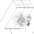
- the access structure 15 shown in Fig. 2 it comprises first and second framework modules 2, 75; fences 36, 37 for the respective framework module 2, 75; a first stairway 38 for the first framework module 2; and a second stairway 39 for reaching the second framework module 75.
- Both stairways 38, 39 are however mounted at the first framework module 2, at respective bottom and top entrance stairway connection portions 10, 70.
- the bottom entrance stairway connection portion 10 used by the first stairway 38 simply is provided by the edge beams 3, 4 of the bottom frame 13 and the floor frame 14, while the top entrance stairway connection portion 70 used by the second stairway 39 is an end beam 7 of the top frame 21.
- Each stairway 38, 39 comprises a hook portion, which engages with the edge beams to hold the stairway 38, 39 in place.
- the second stairway 39 is a long stairway adapted to reach the first floor, from the ground. In order to have the second stairway 39 mounted at about the same angle irrespective of unevenness of the ground, it is provided with an extension bottom part 40.
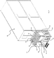
- the framework module 42 is provided with a fixed roof part 43, as however best seen in Fig. 4 , and a sliding roof part 44 comprising three roof pieces 45, 46, 47, constituted by two side pieces 45, 46 arranged at either side of a middle piece 47.
- a sliding roof part 44 comprising three roof pieces 45, 46, 47, constituted by two side pieces 45, 46 arranged at either side of a middle piece 47.
- the securing is made by means of straps 52, which are fastened on one hand at a centre loop 53 at a centre beam 5 of the top frame 55, and on the other hand at fork lift pockets of the modular building 49.
- the centre loop 53 can also be used for raising the framework module from the collapsed state.
- no fork lift pockets are available other attachment are arranged, such as borings in the bottom portion of the modular building 49.
- the access structure 57 has been mounted at a minor distance from the modular building 58, and an end wall of the modular building 58, in order to make room for external connections of for instance water and sanitary conduits to a connection port 59 of the modular building 58 arranged at floor level thereof.
- the sliding roof part 44 i.e. all three roof pieces 45-47, has been pushed rearwards to protrude from the framework module 60 into abutment against the end wall of the modular building 58.
- the access structure 57 comprises an additional floor part 62, and additional fence parts 64.
- the floor 61 of the framework module 57 has been completed with the additional floor part 62, which has been mounted at the rear side of the framework module to cover the distance up to the entrance door of the modular building 58 at floor level, while leaving a floor opening at the connection port 59.
- the fence 63 has been completed with the additional fence parts 64 closing the gaps.
- the framework module 2 is raised in the following way.
- the corner posts 23 In the collapsed state the corner posts 23 have been folded inwards and rest on the floor 11, extending along the floor 11 with the upper portions 24 on top of the lower portions 25.
- the framework module 2 is very compact with a height that is only a fraction of its height in the raised state.
- the framework module 2 is locked in the collapsed state by means of a cotter pin 72 at each corner post 23.
- the cotter pin 72 works as a transport locking device.
- the cotter pin 72 extends through an apertures of the top portion 27 and the bottom portion 28 of the corner post 23.
- the framework module 2 can be raised with any suitable aid, such as a crane lorry. When using straps they can be fastened in for example merely the centre loop 53, or in corner loops 65 at the upper ends of the corner posts 23.
- the corner posts 23 automatically unfolds, as illustrated in Fig. 6 .
- the corner posts 23 have been fully unfolded and have become straight, as shown in Fig. 7 .
- the lower pin 32 at the upper end of the upper portion 24 of each corner post 23 has entered the recess 30 of the associated top portion 27.
- the upper pin 31 is at a lower edge of the through hole 29.
- the top frame 21 is slightly lowered causing the through hole 29 and the recess 30 to move relative to the upper and lower pins 31, 32. This movement results in that the lower pin 31 is fully received in the recess 30, as shown in Fig.
- the second sleeve 35 of each corner post 23 has moved downwards as well, and locks the second hinge portion 67. Finally, the locking elements69 of the first and second sleeves 33, 35 are tightened.
- the framework module 2 is now ready to be lifted in place at a modular building.
Landscapes
- Engineering & Computer Science (AREA)
- Architecture (AREA)
- Physics & Mathematics (AREA)
- Electromagnetism (AREA)
- Civil Engineering (AREA)
- Structural Engineering (AREA)
- Buildings Adapted To Withstand Abnormal External Influences (AREA)
- Joining Of Building Structures In Genera (AREA)
- Residential Or Office Buildings (AREA)
Description
- The present invention relates to an access structure for modular buildings.
- A modular building is a building which is manufactured as individual modules, which can be arranged in different ways to form the building, by means of a single module or several modules. Often these kinds of buildings are temporarily used for some weeks up to some years. Modular buildings include many different buildings, from small site cabins to large multi storey buildings. The modular buildings have to be complemented on site with an access structure, in particular for floors above ground floor, where people otherwise have no access. The access structure includes some kind of base platform, outside the entrance door of the module, and, at least above ground floor, a stair.
Current access structures are often built of wood, which is not satisfactory. The problems are inter alia that the strength of the wooden structures is never calculated, and they are not fire-rated. Besides, they are time consuming to build. There are also access structures built of steel by means of scaffolding, which are neither strength calculated for these kind of applications, nor adapted for use by any person. Therefore, application specific arrangements and complements must be done. Further alternatives are steel structures, which are primarily fastened in the modules, and more particularly in their fork lift pockets. If there are no forklift pockets they are impossible or most difficult to use at all. When the modular building is to be demounted and removed, the current access structures are cumbersome to remove.US3788016 A discloses one example of a mountable and demountable access structure for modular buildings according to the preamble ofclaim 1. It is a portable porch unit for a mobile home. The access structure has a steel framework module containing many parts which are assembled and deassembled. - It would be advantageous to provide a solution for an access structure, which is quick to mount and causes no or little damage to the modular building. This and other objects are achieved by an access structure according to
claim 1 and by a method of mounting an access structure according toclaim 14. According to the invention there is presented an access structure for modular buildings, wherein the access structure is self-contained and comprises a stackable framework module, which has an overall box shape in a mounting state. The framework module comprises vertical and horizontal edge beams, top interconnection portions, for interconnection with another framework module stacked on top of the framework module, bottom interconnection portions, for interconnection with another framework module on top of which the framework module is stacked, an entrance stairway connection portion, a floor and a roof. Thereby, an access structure is provided, which can be used with both single story and multi storey modular buildings, and which is easy to mount and demount at the modular building. - In accordance with an embodiment of the access structure the framework module is positionable at a distance from the modular building, in order to facilitate access to the connections at the wall of the modular building. The framework module has a front side and a rear side, and the roof comprises a sliding part, which is slidable between a position where it has been slided to protrude at the front side, thereby providing an opening through the roof letting a person pass and a position where it has been slided to protrude at the rear side. It is common that the modular building has for instance wall connections for sanitary conduits at floor level, which are hereby given space for. In addition to facilitating mounting, the slidable part of the roof adds a flexibility to the structure as regards the positioning of the structure relative to the modular building with a similar weather protection.
- In accordance with an embodiment of the access structure it comprises an additional floor part, which is arrangeable to cover the distance between the framework module and the modular building at floor level.
- In accordance with an embodiment of the access structure the edge beams comprise bottom beams defining a bottom frame, and floor beams defining a floor frame carrying the floor, wherein the floor frame is positioned a distance above the bottom frame. Thereby the floor is levelled with the entrance door of the module, and room is created beneath the floor for providing fork lift pockets and connection possibilities for additional parts stairways and fence posts, which may be included in the access structure.
- In accordance with an embodiment of the access structure the edge beams comprise vertical corner beams defining four corners of the framework module, and top beams defining a top frame, wherein the corner beams comprise end protrusions, which protrude above the top frame, wherein the top interconnection portions comprise the end protrusions. Thereby a simple yet reliable structure is obtained, and the stacking of the access structures is facilitated.
- In accordance with an embodiment of the access structure the framework module is collapsible and raisable between a collapsed state and a raised state. This embodiment has the advantage of reduced storage and transporting volume.
- In accordance with an embodiment of the access structure the edge beams comprise corner posts defining four corners of the framework module, and top beams defining a top frame connected with the vertical corner beams at a top portion of corner posts, wherein each corner post is foldable.
- In accordance with an embodiment of the access structure each corner post comprises an upper portion and a lower portion, which are hingedly interconnected at a first hinge portion, wherein the upper portion is hingedly and displaceably connected with the top portion, which is fixedly connected with the top frame, and wherein the lower portion is hingedly interconnected with a fixed bottom portion of the corner post at a second hinge portion.
- In accordance with an embodiment of the access structure each top portion comprises a recess, and wherein each upper portion comprises a pin at an upper end of the upper portion, wherein the pin is arranged to be engaged with the recess when the framework module is in the raised state, and thereby to lock the interconnection between the upper portion and the top portion.
- In accordance with an embodiment of the access structure the framework module comprises a first sleeve, which is arranged at one of the corner posts, and which is movable along the corner post.
- In accordance with an embodiment of the access structure each of the corner posts is provided with a first sleeve, which, in the raised state, is arranged to be positioned at the first hinge portion and lock the first hinge portion. By being positioned at the first hinge portion and thereby covering the hinge portion, the sleeve locks the upper and lower parts in the unfolded straight position and thereby prevents the corner post from folding.
- In accordance with an embodiment of the access structure each corner post is provided with a second sleeve, which is movable along the corner post, and which is arranged to lock the second hinge portion when the framework module is in the raised state. Consequently, the second sleeves serve a similar purpose for the second hinge portions as the first sleeves serve for the first hinge portions.
- In accordance with an embodiment of the access structure each one of the first hinge portions comprises a stiffening element, which is operable to stiffen the first hinge portion in the raised state. The stiffening elements are an additional security detail. The hinge portions are already secured by the sleeves to prevent them from folding. However, by additionally stiffening the hinge portions a second folding prevention is provided and additionally, the user perceives the structure as more rigid and safer since the minor play in the hinge portions when not stiffened is removed.
- According to the invention there is provided a method of mounting an access structure for modular buildings. The method provides corresponding problem solutions and advantages as the access structure.
- The invention will now be described in more detail and with reference to the appended drawings in which:
-
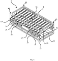
Fig. 1 is a schematic perspective view of an embodiment of the access structure according to the present invention: -
Fig. 2 is a schematic perspective view of an embodiment of the access structure according to the invention mounted at a modular building; -
Fig. 3 is a schematic perspective view of an embodiment of the access structure according to the invention mounted at a modular building; -
Fig. 4 is a schematic perspective view of an embodiment of the access structure according to the invention showing an alternative mounting; -
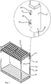
Figs. 5 to 8 are schematic perspective views illustrating raising a framework module included in the access structure from a collapsed state to a raised state. - According to an embodiment of the
access structure 1 it comprises astackable framework module 2, which has an overall box shape in a mounting state, as shown for example inFig. 1 . Theframework module 2 comprises vertical andhorizontal edge beams top interconnection portions 8, for interconnection with anotherframework module 75, also included in theaccess structure 1, as shown inFig. 2 , stacked on top of theframework module 2,bottom interconnection portions 9, for interconnection with another framework module on top of which theframework module 2 is stacked, an entrancestairway connection portion 10, 70 afloor 11 and aroof 12. The edge beams are e.g. made by square tubes, but any useful beam profile will do as recognized by the person skilled in the art. Some of the edge beams constitutebottom beams 3, which define abottom frame 13, andfloor beams 4, which define afloor frame 14. More particularly, thebottom frame 13 and thefloor frame 14 are two rectangles of edge beams, one on top of the other, with a distance between them. Thefloor 11 is attached to thefloor frame 14. Thebottom frame 13 rests on the ground. - The
roof 12 comprises afixed part 16 extending from afront side 17 of theframework module 2 and towards arear side 18 of theframework module 2, covering a fraction of the distance between thefront side 17 and therear side 18. Thefront side 17 can also be defined as a vertical side plane defined by some of the edge beams, and therear side 18 can also be defined as a vertical side plane defined by the some other of the edge beams. Thefixed part 16 covers about half the depth of theframework module 2, i.e. the distance from between thefront side 17 and therear side 18. Further, theroof 12 comprises a slidingroof part 19, which is slidable between an open position, and a rearwards protruding position. In the open position, the slidingroof part 19 provides an opening extending across about a rear half of the depth of theframework module 2. The opening provides for the passage of a person who is to fasten theframework module 2 at the modular building, as will be explained below, or do some other work requiring access to the top area of theframework module 2, the modular building, or anotherframework module 75 placed on top of the first one. In the rearwards protruding position, the slidingroof part 19 protrudes from therear side 18. Typically, the slidingroof part 19 has been pushed into abutment against the wall of the modular building in order to shield the entrance to the modular building from rain. - Furthermore, the edge beams 3-7 comprise
vertical corner beams 6 defining four corners of the framework module, andtop beams 7 defining atop frame 21. Each one of the vertical corner beams 6 comprises anend protrusion 22, which protrudes above thetop frame 21. The end protrusions 22 are comprised in the above-mentionedtop interconnection portions 8. - Furthermore, in this embodiment, the
framework module 2 is raisable and collapsible, and it is shown in a collapsed state inFig. 5 , and in a raised state in, for instance,Fig. 1 . In order to obtain this the edge beams 3-7 comprise corner posts 23, comprising the corner beams 6, and defining four corners of theframework module 2, wherein eachcorner post 23 is foldable. The corner posts 23 are connected with thetop frame 21 at atop portion 27 of eachcorner post 23. - Each corner post 23 comprises an
upper portion 24 and alower portion 25, which are hingedly interconnected, at a commonfirst hinge portion 26. Additionally, theupper portion 24 is hingedly and displaceably connected with thetop portion 27, which is fixedly connected with thetop frame 21. Thelower portion 25 is hingedly connected, at asecond hinge portion 67, with a fixedbottom portion 28 of thecorner post 23. Furthermore, eachtop portion 27 comprises a vertically, i.e. along the length of thetop portion 27, elongated throughhole 29, and arecess 30, which opens to one side of thetop portion 27. Therecess 30 is positioned below the throughhole 29. Eachupper portion 24 comprises twopins upper pin 31 and alower pin 32, at an upper end of theupper portion 24. Theupper pin 31 extends through the throughhole 29, and thereby forms a hinge. Thelower pin 32 is arranged to be engaged with therecess 30 when theframework module 2 is in the raised state, and thereby to lock the interconnection between the upper portion and the top portion. The length of the throughhole 29 exceeds the width of theupper pin 31, which is thus arranged with a play in the throughhole 29. Therecess 30 extends obliquely towards the top of thetop portion 27 forming a seat where thelower pin 32 can be retained. - The
framework module 2 further comprises at least onefirst sleeve 33, and in this embodiment four first sleeves, each arranged at a respective one of the corner posts 23. Thesleeves 33 are movable along the corner posts 23. Thefirst sleeve 33 is meant to be positioned at thefirst hinge portion 26 to enclose and lock thefirst hinge portion 26 when theframework module 2 is in the raised state. - Each corner post 23 is, additionally, provided with a
second sleeve 35, which is movable along thecorner post 23, and which is arranged to lock asecond hinge portion 67, i.e. the hinged interconnection between the lower portion and the bottom portion when the framework module is in the raised state. - Furthermore, the each one of the first and
second hinge portions stiffening element 69, such as a screw acting on a locking member. In this embodiment, thehinge portion lower parts stiffening element 69 is a screw arranged in the middle element. When the screw is tightened it protrudes into abutment against the inner wall of thesleeve hinge portion sleeve element 69 at thefirst hinge portion 26 is tightened thefirst hinge portion 26 is stiffened, i.e. the upper andlower portions sleeve 33. The similar stiffening is obtained at thesecond hinge portion 67 by tightening the stiffeningelement 69 at thesecond hinge portion 67. Thereby the user perceives theframework module 2 more stable and rigid, although it is not necessary from a perspective of strength. The first andsecond sleeves stiffening element 69 through the wall of thesleeve sleeves second hinge portions - It should be noted that even if all
sleeves hinge portions element 69 has been tightened, theframework module 2 will keep standing due to the pin locking arrangement at the top of the corner posts 23. - According to an embodiment of the
access structure 15 shown inFig. 2 it comprises first andsecond framework modules fences respective framework module first stairway 38 for thefirst framework module 2; and asecond stairway 39 for reaching thesecond framework module 75. Bothstairways first framework module 2, at respective bottom and top entrancestairway connection portions stairway connection portion 10 used by thefirst stairway 38 simply is provided by the edge beams 3, 4 of thebottom frame 13 and thefloor frame 14, while the top entrancestairway connection portion 70 used by thesecond stairway 39 is anend beam 7 of thetop frame 21. Eachstairway stairway second stairway 39 is a long stairway adapted to reach the first floor, from the ground. In order to have thesecond stairway 39 mounted at about the same angle irrespective of unevenness of the ground, it is provided with an extensionbottom part 40. - Referring to
Fig. 3 , theframework module 42 is provided with a fixedroof part 43, as however best seen inFig. 4 , and a slidingroof part 44 comprising threeroof pieces side pieces middle piece 47. When theside pieces modular building 49 at which theframework module 42 is mounted,openings access structure 41 has been mounted at a long side of themodular building 49. A person is able to pass theopenings framework module 42 to themodular building 49. For instance, the securing is made by means ofstraps 52, which are fastened on one hand at acentre loop 53 at acentre beam 5 of thetop frame 55, and on the other hand at fork lift pockets of themodular building 49. Thecentre loop 53 can also be used for raising the framework module from the collapsed state. When no fork lift pockets are available other attachment are arranged, such as borings in the bottom portion of themodular building 49. - As shown in
Fig. 4 , theaccess structure 57 has been mounted at a minor distance from themodular building 58, and an end wall of themodular building 58, in order to make room for external connections of for instance water and sanitary conduits to aconnection port 59 of themodular building 58 arranged at floor level thereof. The slidingroof part 44, i.e. all three roof pieces 45-47, has been pushed rearwards to protrude from theframework module 60 into abutment against the end wall of themodular building 58. Furthermore, theaccess structure 57 comprises anadditional floor part 62, andadditional fence parts 64. Thus, thefloor 61 of theframework module 57 has been completed with theadditional floor part 62, which has been mounted at the rear side of the framework module to cover the distance up to the entrance door of themodular building 58 at floor level, while leaving a floor opening at theconnection port 59. Similarly, thefence 63 has been completed with theadditional fence parts 64 closing the gaps. - As illustrated in
Figs. 5-8 , theframework module 2 is raised in the following way. In the collapsed state the corner posts 23 have been folded inwards and rest on thefloor 11, extending along thefloor 11 with theupper portions 24 on top of thelower portions 25. Thereby theframework module 2 is very compact with a height that is only a fraction of its height in the raised state. Theframework module 2 is locked in the collapsed state by means of acotter pin 72 at eachcorner post 23. Thecotter pin 72 works as a transport locking device. Thecotter pin 72 extends through an apertures of thetop portion 27 and thebottom portion 28 of thecorner post 23. Theframework module 2 can be raised with any suitable aid, such as a crane lorry. When using straps they can be fastened in for example merely thecentre loop 53, or incorner loops 65 at the upper ends of the corner posts 23. - During the raising of the
framework module 2 the corner posts 23 automatically unfolds, as illustrated inFig. 6 . When the corner posts 23 have been fully unfolded and have become straight, as shown inFig. 7 , thelower pin 32 at the upper end of theupper portion 24 of eachcorner post 23 has entered therecess 30 of the associatedtop portion 27. Similarly, theupper pin 31 is at a lower edge of the throughhole 29. Then, thetop frame 21 is slightly lowered causing the throughhole 29 and therecess 30 to move relative to the upper andlower pins lower pin 31 is fully received in therecess 30, as shown inFig. 8 , which thereby locks thelower pin 32, and consequently the upper andlower pins corner post 23 straight and prevents the corner post 23 from folding. This pin lock provides enough stability to the corner posts 23 to keep them from folding again when the lifting device is lowered to be loosened from theframework module 2. When theframework module 2 has been raised, thefirst sleeve 33 of eachcorner post 23 has moved down, by gravity, to a position where it locks thefirst hinge portion 26 between the upper andlower portions corner post 23. Thefirst sleeve 33 is prevented from moving further down by astop lug 66 comprised in thelower portion 25 just below thefirst hinge portion 26, see alsoFig. 1 . Thesecond sleeve 35 of eachcorner post 23 has moved downwards as well, and locks thesecond hinge portion 67. Finally, the locking elements69 of the first andsecond sleeves framework module 2 is now ready to be lifted in place at a modular building. - While the invention has been illustrated and described in detail in the drawings and foregoing description, such illustration and description are to be considered illustrative or exemplary and not restrictive; the invention is not limited to the disclosed embodiments.
- Other variations to the disclosed embodiments can be understood and effected by those skilled in the art in practicing the claimed invention, from a study of the drawings, the disclosure, and the appended claims. In the claims, the word "comprising" does not exclude other elements or steps, and the indefinite article "a" or "an" does not exclude a plurality. The mere fact that certain measures are recited in mutually different dependent claims does not indicate that a combination of these measured cannot be used to advantage. Any reference signs in the claims should not be construed as limiting the scope.
Claims (15)
- A mountable and demountable access structure for modular buildings, wherein the access structure (1) comprises a framework module (2), which has an overall box shape in a mounting state, wherein the framework module comprises vertical and horizontal edge beams (3, 4, 5, 6, 7), an entrance stairway connection portion (10, 70), a floor (11) and a roof (12), characterized in that the access structure is self-contained, and in that the framework module is stackable and further comprises top interconnection portions (8), for interconnection with another framework module stacked on top of the framework module, and bottom interconnection portions (9), for interconnection with another framework module on top of which the framework module is stacked.
- The access structure according to claim 1, wherein the framework module is positionable at a distance from the modular building, in order to facilitate access to the connections at the wall of the modular building, wherein the framework module (2) has a front side (17) and a rear side (18), wherein the roof (12) comprises a sliding part (19), which is slidable between a position where it has been slided to protrude at the front side, thereby providing an opening through the roof letting a person pass, and a position where it has been slided to protrude at the rear side.
- The access structure according to claim 2, comprising an additional floor part (62), which is arrangeable to cover the distance between the framework module (2) and the modular building at floor level.
- The access structure according to claim 1, 2, or 3, wherein the edge beams (3, 4, 5, 6, 7) comprise bottom beams (3) defining a bottom frame (13), and floor beams (4) defining a floor frame (14) carrying the floor (11), wherein the floor frame is positioned a distance above the bottom frame.
- The access structure according to any one of the preceding claims, wherein the edge beams (3, 4, 5, 6, 7) comprise vertical corner beams (6) defining four corners of the framework module (2), and top beams (7) defining a top frame (21), wherein the corner beams comprise end protrusions (22), which protrude above the top frame, wherein the top interconnection portions (8) comprise the end protrusions.
- The access structure according to any one of the preceding claims, wherein the framework module (2) is collapsible and raisable between a collapsed state and a raised state.
- The access structure according to claim 6, wherein the edge beams (3, 4, 5, 6, 7) comprise corner posts (23) defining four corners of the framework module (2), and top beams (7) defining a top frame connected with the corner posts at a top portion (27) of the corner posts, wherein each corner post is foldable.
- The access structure according to claim 7, wherein each corner post (23) comprises an upper portion (24) and a lower portion (25), which are hingedly interconnected at a first hinge portion (26), wherein the upper portion is hingedly and displaceably connected with the top portion (27), which is fixedly connected with the top frame (21), and wherein the lower portion is hingedly interconnected with a fixed bottom portion (28) of the corner post at a second hinge portion (67).
- The access structure according to claim 8, wherein each top portion (27) comprises a recess (30), and wherein each upper portion (24) comprises a pin (32) at an upper end of the upper portion, wherein the pin is arranged to be engaged with the recess when the framework module (2) is in the raised state, and thereby to lock the interconnection between the upper portion and the top portion.
- The access structure according to claim 8 or 9, wherein the framework module (2) comprises a first sleeve (33), which is arranged at one of the corner posts (23), and which is movable along the corner post.
- The access structure according to claim 10, wherein each of the corner posts (23) is provided with a first sleeve (33), which, in the raised state, is arranged to be positioned at the first hinge portion (26) and lock the first hinge portion.
- The access structure according to any one of claims 8 to 11, wherein each corner post (23) is provided with a second sleeve (35), which is movable along the corner post, and which is arranged to lock the second hinge portion (67) when the framework module (2) is in the raised state.
- The access structure according to any one of claims 8 to 12, wherein each one of the first hinge portions (26) comprises a stiffening element (69), which is operable to stiffen the first hinge portion in the raised state.
- A method of mounting an access structure for modular buildings, wherein the access structure (1) is according to claim 1, characterized by:- lifting a first framework module in place at a modular building;- lifting a second framework module in place on top of the first access structure, wherein the bottom interconnection portions (9) of the second framework module are engaged with the top interconnection portions (8) of the first framework module; and- mounting an entrance stairway (38) at the entrance stairway connection portion at an upper portion of the first framework module.
- The method according to claim 14, further comprising:- moving a slidable part (19) of a roof (12) of the framework module (2) to obtain an opening, and securing a top portion of the framework module at the modular building through the opening.
Priority Applications (4)
| Application Number | Priority Date | Filing Date | Title |
|---|---|---|---|
| EP16155590.9A EP3205785B1 (en) | 2016-02-12 | 2016-02-12 | Access structure for modular buildings |
| DK16155590.9T DK3205785T3 (en) | 2016-02-12 | 2016-02-12 | INPUT STRUCTURE FOR MODULE BUILDINGS |
| PL16155590T PL3205785T3 (en) | 2016-02-12 | 2016-02-12 | Access structure for modular buildings |
| LTEP16155590.9T LT3205785T (en) | 2016-02-12 | 2016-02-12 | Access structure for modular buildings |
Applications Claiming Priority (1)
| Application Number | Priority Date | Filing Date | Title |
|---|---|---|---|
| EP16155590.9A EP3205785B1 (en) | 2016-02-12 | 2016-02-12 | Access structure for modular buildings |
Publications (2)
| Publication Number | Publication Date |
|---|---|
| EP3205785A1 EP3205785A1 (en) | 2017-08-16 |
| EP3205785B1 true EP3205785B1 (en) | 2018-08-29 |
Family
ID=55453004
Family Applications (1)
| Application Number | Title | Priority Date | Filing Date |
|---|---|---|---|
| EP16155590.9A Active EP3205785B1 (en) | 2016-02-12 | 2016-02-12 | Access structure for modular buildings |
Country Status (4)
| Country | Link |
|---|---|
| EP (1) | EP3205785B1 (en) |
| DK (1) | DK3205785T3 (en) |
| LT (1) | LT3205785T (en) |
| PL (1) | PL3205785T3 (en) |
Families Citing this family (3)
| Publication number | Priority date | Publication date | Assignee | Title |
|---|---|---|---|---|
| CN111779139B (en) * | 2020-08-14 | 2021-08-06 | 浙江正立高科建设有限公司 | A prefabricated building structure system and construction method |
| CN113833321A (en) * | 2021-11-04 | 2021-12-24 | 安捷诚栋国际集成房屋(北京)有限公司 | Modularized integrated box-type house frame structure and box-type house |
| CN119711643B (en) * | 2025-01-09 | 2025-10-24 | 重庆大学 | Retractable and foldable building structure skeleton |
Family Cites Families (3)
| Publication number | Priority date | Publication date | Assignee | Title |
|---|---|---|---|---|
| US3788016A (en) * | 1972-05-17 | 1974-01-29 | J Richardson | Portable porch unit for mobile homes |
| US4852309A (en) * | 1988-06-08 | 1989-08-01 | Stamp Sr Homer M | Modular porch for a mobile home |
| DE20305795U1 (en) * | 2003-04-10 | 2003-06-26 | G T M Gitterroste + Treppen GmbH, 46354 Südlohn | Method for access to container accommodation units with a modular assembly framework with platform and steps |
-
2016
- 2016-02-12 EP EP16155590.9A patent/EP3205785B1/en active Active
- 2016-02-12 DK DK16155590.9T patent/DK3205785T3/en active
- 2016-02-12 PL PL16155590T patent/PL3205785T3/en unknown
- 2016-02-12 LT LTEP16155590.9T patent/LT3205785T/en unknown
Also Published As
| Publication number | Publication date |
|---|---|
| LT3205785T (en) | 2018-10-25 |
| EP3205785A1 (en) | 2017-08-16 |
| PL3205785T3 (en) | 2019-05-31 |
| DK3205785T3 (en) | 2018-11-05 |
Similar Documents
| Publication | Publication Date | Title |
|---|---|---|
| US5127492A (en) | Scaffolding | |
| CN104114784A (en) | Height-adjustable pillars for building structures in shipping containers | |
| US5653459A (en) | Transportable modular landing assembly for a trailer | |
| US10940380B2 (en) | Fast-rope training apparatus | |
| US20110011674A1 (en) | Ladder equipped with safety bar | |
| KR20100099159A (en) | Extendible height container and shelter | |
| US20200407998A1 (en) | Rapidly deployable modular shelter system | |
| WO2016131839A1 (en) | Collapsible elevated platforms | |
| US20200109039A1 (en) | Foldable Personnel Basket For A Crane | |
| EP3205785A1 (en) | Access structure for modular buildings | |
| US20100096216A1 (en) | Scaffolding | |
| US9550661B2 (en) | Self-contained, portable and self-supporting scaffolding kit | |
| CN1965136A (en) | Combined multi-layer channel platform and its construction method | |
| US9938720B2 (en) | Support structure module and modular beam structure | |
| US20180370781A1 (en) | Foldable Personnel Basket For A Crane | |
| GB2431427A (en) | Scaffolding guard rail | |
| EP4186816B1 (en) | Telescopic shipping container | |
| EP1611288A1 (en) | Transportable safety module construction | |
| AU649856B2 (en) | Cantilever scaffold device | |
| WO2012064204A2 (en) | A scaffold and method for construction of same | |
| EP1500754A2 (en) | Improvements in or relating to an access platform | |
| KR102230963B1 (en) | Variable Type boarding box of high place works car | |
| CN118056054A (en) | Scaffold tower and scaffold and use of a tower and scaffold | |
| US10612257B2 (en) | Supervised swimming pool gateway | |
| WO2004097130A1 (en) | A transportable building and self-levelling chassis therefor |
Legal Events
| Date | Code | Title | Description |
|---|---|---|---|
| PUAI | Public reference made under article 153(3) epc to a published international application that has entered the european phase |
Free format text: ORIGINAL CODE: 0009012 |
|
| STAA | Information on the status of an ep patent application or granted ep patent |
Free format text: STATUS: THE APPLICATION HAS BEEN PUBLISHED |
|
| AK | Designated contracting states |
Kind code of ref document: A1 Designated state(s): AL AT BE BG CH CY CZ DE DK EE ES FI FR GB GR HR HU IE IS IT LI LT LU LV MC MK MT NL NO PL PT RO RS SE SI SK SM TR |
|
| AX | Request for extension of the european patent |
Extension state: BA ME |
|
| STAA | Information on the status of an ep patent application or granted ep patent |
Free format text: STATUS: REQUEST FOR EXAMINATION WAS MADE |
|
| GRAP | Despatch of communication of intention to grant a patent |
Free format text: ORIGINAL CODE: EPIDOSNIGR1 |
|
| STAA | Information on the status of an ep patent application or granted ep patent |
Free format text: STATUS: GRANT OF PATENT IS INTENDED |
|
| 17P | Request for examination filed |
Effective date: 20180216 |
|
| RBV | Designated contracting states (corrected) |
Designated state(s): AL AT BE BG CH CY CZ DE DK EE ES FI FR GB GR HR HU IE IS IT LI LT LU LV MC MK MT NL NO PL PT RO RS SE SI SK SM TR |
|
| INTG | Intention to grant announced |
Effective date: 20180327 |
|
| GRAS | Grant fee paid |
Free format text: ORIGINAL CODE: EPIDOSNIGR3 |
|
| GRAA | (expected) grant |
Free format text: ORIGINAL CODE: 0009210 |
|
| STAA | Information on the status of an ep patent application or granted ep patent |
Free format text: STATUS: THE PATENT HAS BEEN GRANTED |
|
| AK | Designated contracting states |
Kind code of ref document: B1 Designated state(s): AL AT BE BG CH CY CZ DE DK EE ES FI FR GB GR HR HU IE IS IT LI LT LU LV MC MK MT NL NO PL PT RO RS SE SI SK SM TR |
|
| REG | Reference to a national code |
Ref country code: GB Ref legal event code: FG4D |
|
| REG | Reference to a national code |
Ref country code: CH Ref legal event code: EP |
|
| REG | Reference to a national code |
Ref country code: AT Ref legal event code: REF Ref document number: 1035295 Country of ref document: AT Kind code of ref document: T Effective date: 20180915 |
|
| REG | Reference to a national code |
Ref country code: IE Ref legal event code: FG4D |
|
| REG | Reference to a national code |
Ref country code: DE Ref legal event code: R096 Ref document number: 602016005047 Country of ref document: DE |
|
| REG | Reference to a national code |
Ref country code: DK Ref legal event code: T3 Effective date: 20181022 |
|
| REG | Reference to a national code |
Ref country code: EE Ref legal event code: FG4A Ref document number: E016305 Country of ref document: EE Effective date: 20181004 |
|
| REG | Reference to a national code |
Ref country code: NL Ref legal event code: MP Effective date: 20180829 |
|
| REG | Reference to a national code |
Ref country code: SE Ref legal event code: TRGR |
|
| REG | Reference to a national code |
Ref country code: NO Ref legal event code: T2 Effective date: 20180829 |
|
| PG25 | Lapsed in a contracting state [announced via postgrant information from national office to epo] |
Ref country code: GR Free format text: LAPSE BECAUSE OF FAILURE TO SUBMIT A TRANSLATION OF THE DESCRIPTION OR TO PAY THE FEE WITHIN THE PRESCRIBED TIME-LIMIT Effective date: 20181130 Ref country code: IS Free format text: LAPSE BECAUSE OF FAILURE TO SUBMIT A TRANSLATION OF THE DESCRIPTION OR TO PAY THE FEE WITHIN THE PRESCRIBED TIME-LIMIT Effective date: 20181229 Ref country code: RS Free format text: LAPSE BECAUSE OF FAILURE TO SUBMIT A TRANSLATION OF THE DESCRIPTION OR TO PAY THE FEE WITHIN THE PRESCRIBED TIME-LIMIT Effective date: 20180829 Ref country code: SE Free format text: LAPSE BECAUSE OF FAILURE TO SUBMIT A TRANSLATION OF THE DESCRIPTION OR TO PAY THE FEE WITHIN THE PRESCRIBED TIME-LIMIT Effective date: 20180829 Ref country code: NL Free format text: LAPSE BECAUSE OF FAILURE TO SUBMIT A TRANSLATION OF THE DESCRIPTION OR TO PAY THE FEE WITHIN THE PRESCRIBED TIME-LIMIT Effective date: 20180829 Ref country code: BG Free format text: LAPSE BECAUSE OF FAILURE TO SUBMIT A TRANSLATION OF THE DESCRIPTION OR TO PAY THE FEE WITHIN THE PRESCRIBED TIME-LIMIT Effective date: 20181129 |
|
| REG | Reference to a national code |
Ref country code: AT Ref legal event code: MK05 Ref document number: 1035295 Country of ref document: AT Kind code of ref document: T Effective date: 20180829 |
|
| PG25 | Lapsed in a contracting state [announced via postgrant information from national office to epo] |
Ref country code: HR Free format text: LAPSE BECAUSE OF FAILURE TO SUBMIT A TRANSLATION OF THE DESCRIPTION OR TO PAY THE FEE WITHIN THE PRESCRIBED TIME-LIMIT Effective date: 20180829 Ref country code: AL Free format text: LAPSE BECAUSE OF FAILURE TO SUBMIT A TRANSLATION OF THE DESCRIPTION OR TO PAY THE FEE WITHIN THE PRESCRIBED TIME-LIMIT Effective date: 20180829 |
|
| REG | Reference to a national code |
Ref country code: SK Ref legal event code: T3 Ref document number: E 29079 Country of ref document: SK |
|
| PG25 | Lapsed in a contracting state [announced via postgrant information from national office to epo] |
Ref country code: AT Free format text: LAPSE BECAUSE OF FAILURE TO SUBMIT A TRANSLATION OF THE DESCRIPTION OR TO PAY THE FEE WITHIN THE PRESCRIBED TIME-LIMIT Effective date: 20180829 Ref country code: IT Free format text: LAPSE BECAUSE OF FAILURE TO SUBMIT A TRANSLATION OF THE DESCRIPTION OR TO PAY THE FEE WITHIN THE PRESCRIBED TIME-LIMIT Effective date: 20180829 Ref country code: RO Free format text: LAPSE BECAUSE OF FAILURE TO SUBMIT A TRANSLATION OF THE DESCRIPTION OR TO PAY THE FEE WITHIN THE PRESCRIBED TIME-LIMIT Effective date: 20180829 Ref country code: ES Free format text: LAPSE BECAUSE OF FAILURE TO SUBMIT A TRANSLATION OF THE DESCRIPTION OR TO PAY THE FEE WITHIN THE PRESCRIBED TIME-LIMIT Effective date: 20180829 |
|
| PG25 | Lapsed in a contracting state [announced via postgrant information from national office to epo] |
Ref country code: SM Free format text: LAPSE BECAUSE OF FAILURE TO SUBMIT A TRANSLATION OF THE DESCRIPTION OR TO PAY THE FEE WITHIN THE PRESCRIBED TIME-LIMIT Effective date: 20180829 |
|
| REG | Reference to a national code |
Ref country code: DE Ref legal event code: R097 Ref document number: 602016005047 Country of ref document: DE |
|
| PLBE | No opposition filed within time limit |
Free format text: ORIGINAL CODE: 0009261 |
|
| STAA | Information on the status of an ep patent application or granted ep patent |
Free format text: STATUS: NO OPPOSITION FILED WITHIN TIME LIMIT |
|
| 26N | No opposition filed |
Effective date: 20190531 |
|
| PG25 | Lapsed in a contracting state [announced via postgrant information from national office to epo] |
Ref country code: SI Free format text: LAPSE BECAUSE OF FAILURE TO SUBMIT A TRANSLATION OF THE DESCRIPTION OR TO PAY THE FEE WITHIN THE PRESCRIBED TIME-LIMIT Effective date: 20180829 |
|
| REG | Reference to a national code |
Ref country code: CH Ref legal event code: PL |
|
| PG25 | Lapsed in a contracting state [announced via postgrant information from national office to epo] |
Ref country code: MC Free format text: LAPSE BECAUSE OF FAILURE TO SUBMIT A TRANSLATION OF THE DESCRIPTION OR TO PAY THE FEE WITHIN THE PRESCRIBED TIME-LIMIT Effective date: 20180829 Ref country code: LU Free format text: LAPSE BECAUSE OF NON-PAYMENT OF DUE FEES Effective date: 20190212 |
|
| REG | Reference to a national code |
Ref country code: BE Ref legal event code: MM Effective date: 20190228 |
|
| REG | Reference to a national code |
Ref country code: IE Ref legal event code: MM4A |
|
| PG25 | Lapsed in a contracting state [announced via postgrant information from national office to epo] |
Ref country code: CH Free format text: LAPSE BECAUSE OF NON-PAYMENT OF DUE FEES Effective date: 20190228 Ref country code: LI Free format text: LAPSE BECAUSE OF NON-PAYMENT OF DUE FEES Effective date: 20190228 |
|
| PG25 | Lapsed in a contracting state [announced via postgrant information from national office to epo] |
Ref country code: IE Free format text: LAPSE BECAUSE OF NON-PAYMENT OF DUE FEES Effective date: 20190212 |
|
| PG25 | Lapsed in a contracting state [announced via postgrant information from national office to epo] |
Ref country code: BE Free format text: LAPSE BECAUSE OF NON-PAYMENT OF DUE FEES Effective date: 20190228 |
|
| PG25 | Lapsed in a contracting state [announced via postgrant information from national office to epo] |
Ref country code: TR Free format text: LAPSE BECAUSE OF FAILURE TO SUBMIT A TRANSLATION OF THE DESCRIPTION OR TO PAY THE FEE WITHIN THE PRESCRIBED TIME-LIMIT Effective date: 20180829 |
|
| PG25 | Lapsed in a contracting state [announced via postgrant information from national office to epo] |
Ref country code: MT Free format text: LAPSE BECAUSE OF NON-PAYMENT OF DUE FEES Effective date: 20190212 Ref country code: PT Free format text: LAPSE BECAUSE OF FAILURE TO SUBMIT A TRANSLATION OF THE DESCRIPTION OR TO PAY THE FEE WITHIN THE PRESCRIBED TIME-LIMIT Effective date: 20181229 |
|
| PG25 | Lapsed in a contracting state [announced via postgrant information from national office to epo] |
Ref country code: CY Free format text: LAPSE BECAUSE OF FAILURE TO SUBMIT A TRANSLATION OF THE DESCRIPTION OR TO PAY THE FEE WITHIN THE PRESCRIBED TIME-LIMIT Effective date: 20180829 |
|
| PG25 | Lapsed in a contracting state [announced via postgrant information from national office to epo] |
Ref country code: HU Free format text: LAPSE BECAUSE OF FAILURE TO SUBMIT A TRANSLATION OF THE DESCRIPTION OR TO PAY THE FEE WITHIN THE PRESCRIBED TIME-LIMIT; INVALID AB INITIO Effective date: 20160212 |
|
| PG25 | Lapsed in a contracting state [announced via postgrant information from national office to epo] |
Ref country code: MK Free format text: LAPSE BECAUSE OF FAILURE TO SUBMIT A TRANSLATION OF THE DESCRIPTION OR TO PAY THE FEE WITHIN THE PRESCRIBED TIME-LIMIT Effective date: 20180829 |
|
| PGFP | Annual fee paid to national office [announced via postgrant information from national office to epo] |
Ref country code: SE Payment date: 20260114 Year of fee payment: 11 |
|
| PGFP | Annual fee paid to national office [announced via postgrant information from national office to epo] |
Ref country code: GB Payment date: 20260115 Year of fee payment: 11 Ref country code: LT Payment date: 20260123 Year of fee payment: 11 |
|
| PGFP | Annual fee paid to national office [announced via postgrant information from national office to epo] |
Ref country code: NO Payment date: 20260116 Year of fee payment: 11 Ref country code: DK Payment date: 20260114 Year of fee payment: 11 Ref country code: DE Payment date: 20260116 Year of fee payment: 11 |
|
| PGFP | Annual fee paid to national office [announced via postgrant information from national office to epo] |
Ref country code: FI Payment date: 20260115 Year of fee payment: 11 |
|
| PGFP | Annual fee paid to national office [announced via postgrant information from national office to epo] |
Ref country code: FR Payment date: 20260113 Year of fee payment: 11 |
|
| PGFP | Annual fee paid to national office [announced via postgrant information from national office to epo] |
Ref country code: CZ Payment date: 20260204 Year of fee payment: 11 |
|
| PGFP | Annual fee paid to national office [announced via postgrant information from national office to epo] |
Ref country code: PL Payment date: 20260112 Year of fee payment: 11 |
|
| PGFP | Annual fee paid to national office [announced via postgrant information from national office to epo] |
Ref country code: EE Payment date: 20260223 Year of fee payment: 11 Ref country code: LV Payment date: 20260213 Year of fee payment: 11 Ref country code: SK Payment date: 20260204 Year of fee payment: 11 |