EP3205582A1 - Total air temperature probe with efficient particle pass through - Google Patents
Total air temperature probe with efficient particle pass through Download PDFInfo
- Publication number
- EP3205582A1 EP3205582A1 EP17155028.8A EP17155028A EP3205582A1 EP 3205582 A1 EP3205582 A1 EP 3205582A1 EP 17155028 A EP17155028 A EP 17155028A EP 3205582 A1 EP3205582 A1 EP 3205582A1
- Authority
- EP
- European Patent Office
- Prior art keywords
- air temperature
- total air
- airflow
- temperature probe
- housing
- Prior art date
- Legal status (The legal status is an assumption and is not a legal conclusion. Google has not performed a legal analysis and makes no representation as to the accuracy of the status listed.)
- Granted
Links
Images


Classifications
-
- G—PHYSICS
- G01—MEASURING; TESTING
- G01K—MEASURING TEMPERATURE; MEASURING QUANTITY OF HEAT; THERMALLY-SENSITIVE ELEMENTS NOT OTHERWISE PROVIDED FOR
- G01K13/00—Thermometers specially adapted for specific purposes
- G01K13/02—Thermometers specially adapted for specific purposes for measuring temperature of moving fluids or granular materials capable of flow
-
- G—PHYSICS
- G01—MEASURING; TESTING
- G01K—MEASURING TEMPERATURE; MEASURING QUANTITY OF HEAT; THERMALLY-SENSITIVE ELEMENTS NOT OTHERWISE PROVIDED FOR
- G01K13/00—Thermometers specially adapted for specific purposes
- G01K13/02—Thermometers specially adapted for specific purposes for measuring temperature of moving fluids or granular materials capable of flow
- G01K13/028—Thermometers specially adapted for specific purposes for measuring temperature of moving fluids or granular materials capable of flow for use in total air temperature [TAT] probes
-
- B—PERFORMING OPERATIONS; TRANSPORTING
- B64—AIRCRAFT; AVIATION; COSMONAUTICS
- B64D—EQUIPMENT FOR FITTING IN OR TO AIRCRAFT; FLIGHT SUITS; PARACHUTES; ARRANGEMENT OR MOUNTING OF POWER PLANTS OR PROPULSION TRANSMISSIONS IN AIRCRAFT
- B64D43/00—Arrangements or adaptations of instruments
-
- B—PERFORMING OPERATIONS; TRANSPORTING
- B64—AIRCRAFT; AVIATION; COSMONAUTICS
- B64D—EQUIPMENT FOR FITTING IN OR TO AIRCRAFT; FLIGHT SUITS; PARACHUTES; ARRANGEMENT OR MOUNTING OF POWER PLANTS OR PROPULSION TRANSMISSIONS IN AIRCRAFT
- B64D45/00—Aircraft indicators or protectors not otherwise provided for
-
- G—PHYSICS
- G01—MEASURING; TESTING
- G01K—MEASURING TEMPERATURE; MEASURING QUANTITY OF HEAT; THERMALLY-SENSITIVE ELEMENTS NOT OTHERWISE PROVIDED FOR
- G01K13/00—Thermometers specially adapted for specific purposes
- G01K13/02—Thermometers specially adapted for specific purposes for measuring temperature of moving fluids or granular materials capable of flow
- G01K13/024—Thermometers specially adapted for specific purposes for measuring temperature of moving fluids or granular materials capable of flow of moving gases
Definitions
- TAT Total air temperature
- Aircraft operators use this measurement and values derived therefrom for, among other things, true air speed calculations and fuel burn monitoring.
- Icing conditions can be problematic for the accuracy of TAT measurements.
- solid particles, ice crystals, ice particles, and/or water droplets can accumulate on the sensing element within the probe, resulting in erroneous measurements.
- Conventional TAT probe designs use streamlined airflow passages and an inertial separation bump to prevent these particles from accumulating on the sensing element; however, these airflow geometries create impact surfaces for ingested particles. Impact surfaces cause deflection, fracturing, and small particle generation that increase the likelihood of accumulation on the sensing element and, as a result, measurement error. Additionally, more accurate TAT measurements may be necessary to meet rising aircraft cost and performance demands.
- a total air temperature probe in one embodiment, includes a housing having inner surfaces defining an airflow passage, a first section of the airflow passage of the housing having an airflow inlet scoop with a first cross-sectional area and an inertial separation bend downstream of the airflow inlet scoop, wherein the airflow passage is configured to be substantially straight; and a second section of the airflow passage of the housing having a main exit channel and an elongated outlet with a second cross-sectional area, wherein the airflow passage is configured to be contoured to direct particle deflections to the elongated outlet, wherein the second section is downstream from the first section, and wherein the first cross-sectional area is greater than the second cross-sectional area.
- a total air temperature probe in another embodiment, includes a housing having inner surfaces defining an airflow passage, a strut connected to and configured to support the housing, a main exit channel formed in the housing, a mouth portion of the main exit channel having a first cross-sectional area defined by an upper portion of an inertial separation bend and a upper portion of a lower exit channel wall, and a throat portion of the of the main exit channel having a second cross-sectional area defined by a lower portion of the inertial separation bend and a lower portion of the lower exit channel wall, wherein the first cross-sectional area is greater than the second cross-sectional area.
- FIG. 1A is a front-facing perspective view of total air temperature (TAT) probe 10.
- FIG. 1B is a rear-facing perspective view of TAT probe 10 shown in FIG. 1A.
- FIG. 1C is a front view of TAT probe 10 shown in FIG. 1A .
- TAT probe 10 includes housing 12, strut 14, mounting region 16, mounting flange 18, electronics housing 20, inlet scoop 22, elongated outlet 24, and external air passage 26.
- Housing 12 is connected to strut 14.
- Strut 14 is connected to housing 12 and mounting region 16.
- Mounting region 16 is connected to strut 14 and mounting flange 18.
- Mounting flange 18 is connected to mounting region 16 and electronics housing 20.
- Inlet scoop 22 is positioned at the front end of housing 12.
- Elongated outlet 24 is positioned at the rear end of housing 12.
- External air passage 26 is positioned between housing 12 and strut 14.
- Housing 12 defines an airflow passage within TAT probe 10 having an inlet at inlet scoop 22 and an outlet at elongated outlet 24. Air enters TAT probe 10 at inlet scoop 22 and a portion of the entering air exits at elongated outlet 24. Elongated outlet 24 provides a larger outlet than conventional TAT probes to ensure that particles are expelled rather than deflected or fractured.
- Strut 14 supports housing 12 and connects to mounting region 16. Mounting region 16 connects strut 14 to mounting flange 18. Mounting flange 18 connects to electronics housing 20 and connects TAT probe 10 to the aircraft. Electronics housing 20 contains the electronic equipment.
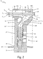
- FIG. 2 is a cross-sectional view TAT probe 10 taken along line 2-2 of FIG. 1C and showing airflow particle trajectories therein.
- TAT probe 10 includes housing 12, strut 14, mounting region 16, mounting flange 18, electronics housing 20, inlet scoop 22, elongated outlet 24, external air passage 26, airflow inlet channel 28 (which includes upper wall 28U and lower wall 28L), main air exit channel 30 (which includes upper exit channel wall 30U and lower exit channel wall 30L), sensor flow channel 32 (which includes front wall 32F and rear wall 32R), inertial separation bend 34, bleed ports 36, sensing element 38, sensing element housing 40, and exit ports 42.
- sections S 1 and S 2 particle trajectories P 1 , P 2 , and P 3 ; airflow axis line L 1 and longitudinal axis line L 2; and angle ⁇ .
- Housing 12 is connected to strut 14.
- Strut 14 is connected to housing 12 and mounting region 16.
- Mounting region 16 is connected to strut 14 and mounting flange 18.
- Mounting flange 18 is connected to mounting region 16 and electronics housing 20.
- Inlet scoop 22 is positioned at the front end of housing 12 in section S 1 .
- Elongated outlet 24 is positioned at the rear end of housing 12 in section S 2 .
- Airflow inlet channel 28 is positioned within section S 1 of housing 12 and has a first end at inlet scoop 22 and a second end at inertial separation bend 34.
- Upper wall 28U of airflow inlet channel 28 is connected to inlet scoop 22 and upper exit channel wall 30U of main air exit channel 30.
- Lower wall 28L of airflow inlet channel 28 is connected to inlet scoop 22 and inertial separation bend 34.
- Inertial separation bend 34 is positioned within section S 1 of housing 12 and is connected to external air passage 26, lower wall 28L, and front wall 32F of sensor flow channel 32.
- Bleed ports 36 are positioned within inertial separation bend 34.
- External air passage 26 is positioned between housing 12 and strut 14 and is connected to housing 12, strut 14, inertial separation bend 34, and bleed ports 36.
- Main air exit channel 30 is positioned within section S 2 of housing 12 and has a first end at inertial separation bend 34 and a second end at elongated outlet 24.
- Upper exit channel wall 30U of main air exit channel 30 is connected to elongated outlet 24 and upper wall 28U.
- Lower exit channel wall 30L of main air exit channel 30 is connected to elongated outlet 24 and rear wall 32R of sensor flow channel 32.
- Sensor flow channel 32 is positioned at the lower end of inertial separation bend 34 and at the lower end of lower exit channel wall 30L.
- Front wall 32F of sensor flow channel 32 is connected to inertial separation bend 34.
- Rear wall 32R of sensor flow channel 32 is connected to lower exit channel wall 30L of main air exit channel 30.
- the upper portion of sensor flow channel 32 is positioned generally along longitudinal axis line L 2 .
- Longitudinal axis line L 2 forms angle ⁇ with airflow axis line L 1 , which represents the direction of travel of free stream airflow. In one embodiment, angle ⁇ can be 120 degrees.
- Sensing element 38 and sensor housing 40 are positioned within sensor flow channel 32.
- Exit ports 42 are positioned in strut 14 and are connected to sensor flow channel 32.
- Free stream airflow enters TAT probe 10 at inlet scoop 22 and proceeds along airflow inlet channel 28 to inertial separation bend 34.
- Inertial separation bend 34 separates the airflow from airflow inlet channel 28 so that one portion of the airflow proceeds to main air exit channel 30 and another portion of the airflow continues to sensor flow channel 32.
- the portion of the airflow proceeding to main air exit channel 30 is then expelled from elongated outlet 24.
- the portion of the airflow entering sensor flow channel 32 engages with sensing element 38.
- the temperature of this airflow portion can be measured by sensing element 38 before being expelled from TAT probe 10 at exit ports 42.
- section S 1 of TAT probe 10 free stream air enters inlet scoop 22 and proceeds along airflow inlet channel 28 to inertial separation bend 34.
- Upper wall 28U and lower wall 28L of airflow inlet channel 28 are configured to be substantially parallel.
- Inertial separation bend 34 remains substantially flat with respect to lower wall 28L, rather than ramping toward upper wall 28U or acting as an air bump.
- This airflow geometry in section S 1 ensures that any solid particles, ice crystals, or ice particles entering airflow inlet channel 28 are less likely to deflect or fracture because there are fewer impact surfaces, while also separating the airflow path to proceed to main air exit channel 30 and sensor flow channel 32.
- Particle trajectories P 1 , P 2 , and P 3 illustrate efficient particle pass through for TAT probe 10, avoiding collision with any of the internal surfaces of airflow inlet channel 28 in section S 1 .
- inertial separation bend 34 diverts one portion of the airflow from airflow inlet channel 28 to main air exit channel 30 and another portion to sensor flow channel 32.
- Upper exit channel wall 30U and lower exit channel wall 30L of main exit channel 30 are contoured to direct particle deflections to elongated outlet 24.
- the cross-sectional area defined by upper exit channel wall 30U and lower exit channel wall 30L decreases in the direction of elongated outlet 24.
- the cross-sectional area defined by inertial separation bend 34 and lower exit channel wall 30L decreases in the direction of mounting flange 18 until reaching wall the upper portion of rear wall 32R.
- the geometry of upper exit channel wall 30U and lower exit channel wall 30L directs particle deflections to elongated outlet 24.
- This geometry also ensures that there is proper restriction on elongated outlet 24 and air stagnation in main air exit channel 30 to facilitate separation of the airflow at inertial separation bend 34.
- particle trajectories P 1 , P 2 , and P 3 avoid collision with any of the internal surfaces of main air exit channel 30 in section S 2 .
- the airflow geometries of sections S 1 and S 2 minimize the likelihood of particle deflections and fracturing and, thus, temperature measurement error in TAT probe 10.
- FIG. 3A is a partial cut away view of prior art TAT probe 100.
- FIG. 3B is a rear view of prior art TAT probe 100 in FIG. 3A .
- Prior art TAT probe 100 includes housing 112, strut 114, mounting flange 118, electronics housing 120, inlet scoop 122, outlet 124, external air passage 126, airflow inlet channel 128 (which includes upper wall 128U and inlet flow ramp 128R), main air exit channel 130 (which includes air bump 130B and lower exit channel wall 130L), sensor flow channel 132, inertial separation bump 134, bleed ports 136, sensing element 138, sensing element housing 140, and exit ports 142. Also included in FIG. 3A is free stream airflow A.
- Housing 112 is connected to strut 114.
- Strut 114 is connected to housing 112 and mounting flange 118.
- Mounting flange 118 is connected to strut 114 and electronics housing 120.
- Inlet scoop 122 is positioned at the front end of housing 112.
- Outlet 124 is positioned at the rear end of housing 112.
- Airflow inlet channel 128 is positioned within housing 112 and has a first end at inlet scoop 122 and a second end at inertial separation bump 134.
- Upper wall 128U of airflow inlet channel 128 is connected to inlet scoop 122 and air bump 130B of main air exit channel 130.
- Inlet flow ramp 128R of airflow inlet channel 128 is connected to inlet scoop 122 and to inertial separation bump 134.
- Inertial separation bump 134 is positioned within housing 112 and is connected to inlet flow ramp 128R. Bleed ports 136 are positioned within inertial separation bump 134.
- External air passage 126 is positioned between housing 112 and strut 114 and is connected to housing 112, strut 114, inertial separation bump 134, and bleed ports 136.
- Main air exit channel 130 is positioned within housing 112 and has a first end at inertial separation bump 134 and a second end at outlet 124. Air bump 130B of main air exit channel 130 is connected to outlet 124 and upper wall 128U. Lower lip 130L of main air exit channel 130 is connected to outlet 124 and sensor flow channel 132.
- Sensor flow channel 132 is positioned at the lower end of inertial separation bump 134 and at lower lip 130L of main air exit channel 130. Sensing element 138 and sensor housing 140 are positioned within sensor flow channel 132. Exit ports 142 are positioned in strut 114 and are connected to sensor flow channel 132.
- Free stream airflow A enters prior art TAT probe 100 at inlet scoop 122 and proceeds along airflow inlet channel 128 to inertial separation bump 134.
- Both lower inlet flow ramp 128R and inertial separation bump 134 angle upward toward upper inlet flow wall 28U, constricting airflow A in airflow inlet channel 128.
- Inertial separation bump 134 separates airflow A so that one portion of airflow A proceeds to main air exit channel 130 and another portion of airflow A continues to sensor flow channel 132.
- the portion of airflow A proceeding to main air exit channel 130 travels around air bump 130B and over lower lip 130L and is then expelled from outlet 124.
- the portion of airflow A entering sensor flow channel 132 engages with sensing element 138.
- the temperature of this airflow portion can be measured by sensing element 138 before being expelled from TAT probe 100 at exit ports 142.
- Airflow A is constricted as airflow inlet channel 128 narrows and at air bump 130B in main air exit channel 130.
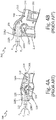
- FIG. 4A is a cross-sectional view of prior art TAT probe 100 shown in in FIGS. 3A and 3B including particle trajectories therein.
- Prior art TAT probe 100 includes housing 112, strut 114, inlet scoop 122, outlet 124, airflow inlet channel 128 (which includes upper wall 128U and inlet flow ramp 128R), main air exit channel 130 (which includes air bump 130B and lower exit channel wall 130L), sensor flow channel 132, and inertial separation bump 134.
- particle trajectories P 1 , P 2 , and P 3 are also included in FIG. 4A .
- inlet flow ramp 128R, inertial separation bump 134, air bump 130B, and over lower lip 130L can act is impact surfaces for solid particles, ice crystals, or ice particles causing deflection and fracturing thereof.
- Particle trajectory P 1 collides with air bump 130B and deflects toward the sensing element.
- Particle trajectories P 2 and P 3 strike and deflect from inertial separation bump 134 and upper wall 128U. Such collisions increase the likelihood of particles accumulating at the sensing element.
- FIG. 4B is a cross-sectional view of prior art TAT probe 200 showing particle trajectories therein.
- Prior art TAT probe 200 includes housing 212, strut 214, inlet scoop 222, outlet 224, airflow inlet channel 228 (which includes upper wall 228U and lower wall 228L), main air exit channel 230 (which includes upper exit channel wall 230U and lower exit channel wall 230L), sensor flow channel 232, and inertial separation bump 234.
- Free stream airflow enters prior art TAT probe 200 at inlet scoop 222 and directed along airflow inlet channel 228 to inertial separation bump 234.
- Both lower inlet flow ramp 228R and inertial separation bump 234 ramp upward toward upper inlet flow wall 228U.
- Inertial separation bump 234 separates the airflow from airflow inlet channel 228 so that one portion of the airflow proceeds to main air exit channel 230 and another portion of the airflow continues to sensor flow channel 232.
- Particle trajectories P 1 , P 2 , and P 3 illustrate that upper wall 228U can act as impact surfaces for solid particles, ice crystals, or ice particles causing deflection and fracturing thereof.
- Particle trajectories P 1 , P 2 , and P 3 strike and collide with upper exit channel wall 230U and deflect in in the direction of sensor flow channel 232, increasing the likelihood of measurement error due to particle accretion at the sensing element.
- a total air temperature probe includes a housing having inner surfaces defining an airflow passage, a first section of the airflow passage of the housing having an airflow inlet scoop with a first cross-sectional area and an inertial separation bend downstream of the airflow inlet scoop, wherein the airflow passage is configured to be substantially straight, and a second section of the airflow passage of the housing having a main exit channel and an elongated outlet with a second cross-sectional area, wherein the airflow passage is contoured to direct particle deflections to the elongated outlet, wherein the second section is downstream from the first section, and wherein the first cross-sectional area is greater than the second cross-sectional area.
- the total air temperature probe of the preceding paragraph can optionally include, additionally and/or alternatively, any one or more of the following features, configurations and/or additional components:
- the total air temperature probe wherein a portion of the sensor flow passage extends longitudinally along an axis, that is oriented to form an angle ⁇ with the airflow passage of the first section.
- the total air temperature probe wherein the angle ⁇ is between 115 and 145 degrees.
- the total air temperature probe wherein the total air temperature sensor is configured to measure a total air temperature of an airflow through the sensor flow passage.
- the total air temperature probe wherein the total air temperature probe is mounted to an aircraft surface.
- the total air temperature probe wherein the elongated outlet is obround.
- a total air temperature probe includes a housing having inner surfaces defining an airflow passage, a strut connected to and configured to support the housing, a main exit channel formed in the housing, a mouth portion of the main exit channel having a first cross-sectional area defined by an upper portion of an inertial separation bend and a upper portion of a lower exit channel wall, and a throat portion of the of the main exit channel having a second cross-sectional area defined by a lower portion of the inertial separation bend and a lower portion of the lower exit channel wall, wherein the first cross-sectional area is greater than the second cross-sectional area.
- the total air temperature probe of the preceding paragraph can optionally include, additionally and/or alternatively, any one or more of the following features, configurations and/or additional components:
- the total air temperature probe further comprising an external air passage.
- the total air temperature probe wherein the inertial separation bend includes bleed ports.
- the total air temperature probe wherein the external air passage is configured to be in fluid connection with the bleed ports and the inertial separation bend.
- the total air temperature probe wherein the lower exit channel wall and an upper exit channel wall of the main exit channel are contoured to direct particles to an elongated outlet.
Landscapes
- Physics & Mathematics (AREA)
- General Physics & Mathematics (AREA)
- Engineering & Computer Science (AREA)
- Aviation & Aerospace Engineering (AREA)
- Measuring Temperature Or Quantity Of Heat (AREA)
- Measuring Volume Flow (AREA)
Abstract
Description
- Safe and efficient aircraft operation requires accurate temperature measurements. Total air temperature (TAT) probes, typically positioned outside the fuselage or at the engine inlet, measure the maximum air temperature attained by converting the kinetic energy of the surrounding airstream to thermal energy. TAT probes stagnate the surrounding free stream airflow to measure the static air temperature and the resulting adiabatic rise in temperature. Aircraft operators use this measurement and values derived therefrom for, among other things, true air speed calculations and fuel burn monitoring.
- Icing conditions can be problematic for the accuracy of TAT measurements. During in flight icing conditions, solid particles, ice crystals, ice particles, and/or water droplets can accumulate on the sensing element within the probe, resulting in erroneous measurements. Conventional TAT probe designs use streamlined airflow passages and an inertial separation bump to prevent these particles from accumulating on the sensing element; however, these airflow geometries create impact surfaces for ingested particles. Impact surfaces cause deflection, fracturing, and small particle generation that increase the likelihood of accumulation on the sensing element and, as a result, measurement error. Additionally, more accurate TAT measurements may be necessary to meet rising aircraft cost and performance demands.
- In one embodiment, a total air temperature probe includes a housing having inner surfaces defining an airflow passage, a first section of the airflow passage of the housing having an airflow inlet scoop with a first cross-sectional area and an inertial separation bend downstream of the airflow inlet scoop, wherein the airflow passage is configured to be substantially straight; and a second section of the airflow passage of the housing having a main exit channel and an elongated outlet with a second cross-sectional area, wherein the airflow passage is configured to be contoured to direct particle deflections to the elongated outlet, wherein the second section is downstream from the first section, and wherein the first cross-sectional area is greater than the second cross-sectional area.
- In another embodiment, a total air temperature probe includes a housing having inner surfaces defining an airflow passage, a strut connected to and configured to support the housing, a main exit channel formed in the housing, a mouth portion of the main exit channel having a first cross-sectional area defined by an upper portion of an inertial separation bend and a upper portion of a lower exit channel wall, and a throat portion of the of the main exit channel having a second cross-sectional area defined by a lower portion of the inertial separation bend and a lower portion of the lower exit channel wall, wherein the first cross-sectional area is greater than the second cross-sectional area.
-
-
FIG. 1 A is a front-facing perspective view of a total air temperature (TAT) probe. -
FIG. 1B is a rear-facing perspective view of the TAT probe shown inFIG. 1A . -
FIG. 1C is a front view of the TAT probe shown inFIG. 1A . -
FIG. 2 is a cross-sectional view of the TAT probe showing particle trajectories therein, taken along line 2-2 ofFIG. 1C . -
FIG. 3A is a partial cut away view of a prior art TAT probe. -
FIG. 3B is a rear view of the prior art TAT probe inFIG. 4A . -
FIG. 4A is a cross-sectional view of the prior art TAT probe ofFIGS. 3A and 3B showing particle trajectories therein. -
FIG. 4B is a cross-sectional view of a second prior art TAT probe showing particle trajectories therein. - FIG. 4C is a cross-sectional view of a third prior art TAT probe showing particle trajectories therein.
- FIG. 4D is a cross-sectional view of a fourth prior art TAT probe showing particle trajectories therein.
-
FIG. 1A is a front-facing perspective view of total air temperature (TAT)probe 10.FIG. 1B is a rear-facing perspective view ofTAT probe 10 shown inFIG. 1A. FIG. 1C is a front view ofTAT probe 10 shown inFIG. 1A . TATprobe 10 includeshousing 12,strut 14,mounting region 16,mounting flange 18,electronics housing 20,inlet scoop 22,elongated outlet 24, andexternal air passage 26.Housing 12 is connected tostrut 14.Strut 14 is connected tohousing 12 and mountingregion 16.Mounting region 16 is connected tostrut 14 and mountingflange 18.Mounting flange 18 is connected to mountingregion 16 andelectronics housing 20.Inlet scoop 22 is positioned at the front end ofhousing 12. Elongatedoutlet 24 is positioned at the rear end ofhousing 12.External air passage 26 is positioned betweenhousing 12 andstrut 14. -
Housing 12 defines an airflow passage within TATprobe 10 having an inlet atinlet scoop 22 and an outlet atelongated outlet 24. Air enters TATprobe 10 atinlet scoop 22 and a portion of the entering air exits atelongated outlet 24. Elongatedoutlet 24 provides a larger outlet than conventional TAT probes to ensure that particles are expelled rather than deflected or fractured. Strut 14 supportshousing 12 and connects to mountingregion 16. Mountingregion 16 connectsstrut 14 to mountingflange 18. Mountingflange 18 connects toelectronics housing 20 and connects TATprobe 10 to the aircraft.Electronics housing 20 contains the electronic equipment. -
FIG. 2 is a cross-sectionalview TAT probe 10 taken along line 2-2 ofFIG. 1C and showing airflow particle trajectories therein.TAT probe 10 includeshousing 12,strut 14,mounting region 16,mounting flange 18,electronics housing 20,inlet scoop 22,elongated outlet 24,external air passage 26, airflow inlet channel 28 (which includesupper wall 28U andlower wall 28L), main air exit channel 30 (which includes upper exit channel wall 30U and lowerexit channel wall 30L), sensor flow channel 32 (which includesfront wall 32F andrear wall 32R),inertial separation bend 34,bleed ports 36,sensing element 38,sensing element housing 40, andexit ports 42. Also shown inFIG. 2 are sections S1 and S2; particle trajectories P1, P2, and P3; airflow axis line L1 and longitudinal axis line L2; and angle θ. -
Housing 12 is connected to strut 14.Strut 14 is connected tohousing 12 and mountingregion 16. Mountingregion 16 is connected to strut 14 and mountingflange 18. Mountingflange 18 is connected to mountingregion 16 andelectronics housing 20.Inlet scoop 22 is positioned at the front end ofhousing 12 in section S1. Elongated outlet 24 is positioned at the rear end ofhousing 12 in section S2. -
Airflow inlet channel 28 is positioned within section S1 ofhousing 12 and has a first end atinlet scoop 22 and a second end atinertial separation bend 34.Upper wall 28U ofairflow inlet channel 28 is connected toinlet scoop 22 and upper exit channel wall 30U of mainair exit channel 30.Lower wall 28L ofairflow inlet channel 28 is connected toinlet scoop 22 andinertial separation bend 34.Inertial separation bend 34 is positioned within section S1 ofhousing 12 and is connected toexternal air passage 26,lower wall 28L, andfront wall 32F of sensor flow channel 32. Bleedports 36 are positioned withininertial separation bend 34.External air passage 26 is positioned betweenhousing 12 and strut 14 and is connected tohousing 12,strut 14,inertial separation bend 34, and bleedports 36. - Main
air exit channel 30 is positioned within section S2 ofhousing 12 and has a first end atinertial separation bend 34 and a second end atelongated outlet 24. Upper exit channel wall 30U of mainair exit channel 30 is connected toelongated outlet 24 andupper wall 28U. Lowerexit channel wall 30L of mainair exit channel 30 is connected toelongated outlet 24 andrear wall 32R of sensor flow channel 32. - Sensor flow channel 32 is positioned at the lower end of
inertial separation bend 34 and at the lower end of lowerexit channel wall 30L.Front wall 32F of sensor flow channel 32 is connected toinertial separation bend 34.Rear wall 32R of sensor flow channel 32 is connected to lowerexit channel wall 30L of mainair exit channel 30. The upper portion of sensor flow channel 32 is positioned generally along longitudinal axis line L2. Longitudinal axis line L2 forms angle θ with airflow axis line L1, which represents the direction of travel of free stream airflow. In one embodiment, angle θ can be 120 degrees. Sensingelement 38 andsensor housing 40 are positioned within sensor flow channel 32.Exit ports 42 are positioned instrut 14 and are connected to sensor flow channel 32. - Free stream airflow enters
TAT probe 10 atinlet scoop 22 and proceeds alongairflow inlet channel 28 toinertial separation bend 34.Inertial separation bend 34 separates the airflow fromairflow inlet channel 28 so that one portion of the airflow proceeds to mainair exit channel 30 and another portion of the airflow continues to sensor flow channel 32. The portion of the airflow proceeding to mainair exit channel 30 is then expelled fromelongated outlet 24. The portion of the airflow entering sensor flow channel 32 engages withsensing element 38. The temperature of this airflow portion can be measured by sensingelement 38 before being expelled fromTAT probe 10 atexit ports 42. - In section S1 of
TAT probe 10, free stream air entersinlet scoop 22 and proceeds alongairflow inlet channel 28 toinertial separation bend 34.Upper wall 28U andlower wall 28L ofairflow inlet channel 28 are configured to be substantially parallel.Inertial separation bend 34 remains substantially flat with respect tolower wall 28L, rather than ramping towardupper wall 28U or acting as an air bump. This airflow geometry in section S1 ensures that any solid particles, ice crystals, or ice particles enteringairflow inlet channel 28 are less likely to deflect or fracture because there are fewer impact surfaces, while also separating the airflow path to proceed to mainair exit channel 30 and sensor flow channel 32. Minimizing deflections and fractures of these particles decreases the likelihood of particle accretion on sensingelement 38 ofTAT probe 10, thereby decreasing the likelihood of temperature measurement error. Particle trajectories P1, P2, and P3 illustrate efficient particle pass through forTAT probe 10, avoiding collision with any of the internal surfaces ofairflow inlet channel 28 in section S1. - In section S2 of
TAT probe 10,inertial separation bend 34 diverts one portion of the airflow fromairflow inlet channel 28 to mainair exit channel 30 and another portion to sensor flow channel 32. Upper exit channel wall 30U and lowerexit channel wall 30L ofmain exit channel 30 are contoured to direct particle deflections toelongated outlet 24. The cross-sectional area defined by upper exit channel wall 30U and lowerexit channel wall 30L decreases in the direction ofelongated outlet 24. The cross-sectional area defined byinertial separation bend 34 and lowerexit channel wall 30L decreases in the direction of mountingflange 18 until reaching wall the upper portion ofrear wall 32R. The geometry of upper exit channel wall 30U and lowerexit channel wall 30L directs particle deflections toelongated outlet 24. This geometry also ensures that there is proper restriction onelongated outlet 24 and air stagnation in mainair exit channel 30 to facilitate separation of the airflow atinertial separation bend 34. As in Section S1, particle trajectories P1, P2, and P3 avoid collision with any of the internal surfaces of mainair exit channel 30 in section S2. The airflow geometries of sections S1 and S2 minimize the likelihood of particle deflections and fracturing and, thus, temperature measurement error inTAT probe 10. -
FIG. 3A is a partial cut away view of priorart TAT probe 100.FIG. 3B is a rear view of priorart TAT probe 100 inFIG. 3A . Priorart TAT probe 100 includeshousing 112,strut 114, mountingflange 118,electronics housing 120,inlet scoop 122,outlet 124,external air passage 126, airflow inlet channel 128 (which includesupper wall 128U andinlet flow ramp 128R), main air exit channel 130 (which includesair bump 130B and lowerexit channel wall 130L),sensor flow channel 132,inertial separation bump 134, bleedports 136, sensingelement 138, sensingelement housing 140, andexit ports 142. Also included inFIG. 3A is free stream airflow A. -
Housing 112 is connected to strut 114.Strut 114 is connected tohousing 112 and mountingflange 118. Mountingflange 118 is connected to strut 114 andelectronics housing 120.Inlet scoop 122 is positioned at the front end ofhousing 112.Outlet 124 is positioned at the rear end ofhousing 112.Airflow inlet channel 128 is positioned withinhousing 112 and has a first end atinlet scoop 122 and a second end atinertial separation bump 134.Upper wall 128U ofairflow inlet channel 128 is connected toinlet scoop 122 andair bump 130B of mainair exit channel 130.Inlet flow ramp 128R ofairflow inlet channel 128 is connected toinlet scoop 122 and toinertial separation bump 134.Inertial separation bump 134 is positioned withinhousing 112 and is connected toinlet flow ramp 128R. Bleedports 136 are positioned withininertial separation bump 134.External air passage 126 is positioned betweenhousing 112 and strut 114 and is connected tohousing 112,strut 114,inertial separation bump 134, and bleedports 136. Mainair exit channel 130 is positioned withinhousing 112 and has a first end atinertial separation bump 134 and a second end atoutlet 124.Air bump 130B of mainair exit channel 130 is connected tooutlet 124 andupper wall 128U.Lower lip 130L of mainair exit channel 130 is connected tooutlet 124 andsensor flow channel 132.Sensor flow channel 132 is positioned at the lower end ofinertial separation bump 134 and atlower lip 130L of mainair exit channel 130.Sensing element 138 andsensor housing 140 are positioned withinsensor flow channel 132.Exit ports 142 are positioned instrut 114 and are connected tosensor flow channel 132. - Free stream airflow A enters prior
art TAT probe 100 atinlet scoop 122 and proceeds alongairflow inlet channel 128 toinertial separation bump 134. Both lowerinlet flow ramp 128R andinertial separation bump 134 angle upward toward upper inlet flowwall 28U, constricting airflow A inairflow inlet channel 128.Inertial separation bump 134 separates airflow A so that one portion of airflow A proceeds to mainair exit channel 130 and another portion of airflow A continues tosensor flow channel 132. The portion of airflow A proceeding to mainair exit channel 130 travels aroundair bump 130B and overlower lip 130L and is then expelled fromoutlet 124. The portion of airflow A enteringsensor flow channel 132 engages withsensing element 138. The temperature of this airflow portion can be measured by sensingelement 138 before being expelled fromTAT probe 100 atexit ports 142. Airflow A is constricted asairflow inlet channel 128 narrows and atair bump 130B in mainair exit channel 130. -
FIG. 4A is a cross-sectional view of priorart TAT probe 100 shown in inFIGS. 3A and 3B including particle trajectories therein. Priorart TAT probe 100 includeshousing 112,strut 114,inlet scoop 122,outlet 124, airflow inlet channel 128 (which includesupper wall 128U andinlet flow ramp 128R), main air exit channel 130 (which includesair bump 130B and lowerexit channel wall 130L),sensor flow channel 132, andinertial separation bump 134. Also included inFIG. 4A are particle trajectories P1, P2, and P3. As illustrated by particle trajectories P1, P2, and P3,inlet flow ramp 128R,inertial separation bump 134,air bump 130B, and overlower lip 130L can act is impact surfaces for solid particles, ice crystals, or ice particles causing deflection and fracturing thereof. Particle trajectory P1 collides withair bump 130B and deflects toward the sensing element. Particle trajectories P2 and P3 strike and deflect frominertial separation bump 134 andupper wall 128U. Such collisions increase the likelihood of particles accumulating at the sensing element. -
FIG. 4B is a cross-sectional view of priorart TAT probe 200 showing particle trajectories therein. Priorart TAT probe 200 includeshousing 212,strut 214, inlet scoop 222,outlet 224, airflow inlet channel 228 (which includesupper wall 228U and lower wall 228L), main air exit channel 230 (which includes upper exit channel wall 230U and lower exit channel wall 230L),sensor flow channel 232, andinertial separation bump 234. Free stream airflow enters priorart TAT probe 200 at inlet scoop 222 and directed alongairflow inlet channel 228 toinertial separation bump 234. Both lowerinlet flow ramp 228R andinertial separation bump 234 ramp upward toward upperinlet flow wall 228U.Inertial separation bump 234 separates the airflow fromairflow inlet channel 228 so that one portion of the airflow proceeds to mainair exit channel 230 and another portion of the airflow continues tosensor flow channel 232. Particle trajectories P1, P2, and P3 illustrate thatupper wall 228U can act as impact surfaces for solid particles, ice crystals, or ice particles causing deflection and fracturing thereof. Particle trajectories P1, P2, and P3 strike and collide with upper exit channel wall 230U and deflect in in the direction ofsensor flow channel 232, increasing the likelihood of measurement error due to particle accretion at the sensing element. - The following are non-exclusive descriptions of possible embodiments of the present invention.
- A total air temperature probe according to an exemplary embodiment of this disclosure, among other possible things, includes a housing having inner surfaces defining an airflow passage, a first section of the airflow passage of the housing having an airflow inlet scoop with a first cross-sectional area and an inertial separation bend downstream of the airflow inlet scoop, wherein the airflow passage is configured to be substantially straight, and a second section of the airflow passage of the housing having a main exit channel and an elongated outlet with a second cross-sectional area, wherein the airflow passage is contoured to direct particle deflections to the elongated outlet, wherein the second section is downstream from the first section, and wherein the first cross-sectional area is greater than the second cross-sectional area.
- The total air temperature probe of the preceding paragraph can optionally include, additionally and/or alternatively, any one or more of the following features, configurations and/or additional components:
- The total air temperature probe further comprising a strut connected to and configured to support the housing, a sensor flow passage formed in the strut, and a total air temperature sensor positioned in the sensor flow passage.
- The total air temperature probe wherein a portion of the sensor flow passage extends longitudinally along an axis, that is oriented to form an angle θ with the airflow passage of the first section.
- The total air temperature probe wherein the angle θ is between 115 and 145 degrees.
- The total air temperature probe wherein the total air temperature sensor is configured to measure a total air temperature of an airflow through the sensor flow passage.
- The total air temperature probe wherein the total air temperature probe is mounted to an aircraft surface.
- The total air temperature probe wherein the elongated outlet is obround.
- A total air temperature probe includes a housing having inner surfaces defining an airflow passage, a strut connected to and configured to support the housing, a main exit channel formed in the housing, a mouth portion of the main exit channel having a first cross-sectional area defined by an upper portion of an inertial separation bend and a upper portion of a lower exit channel wall, and a throat portion of the of the main exit channel having a second cross-sectional area defined by a lower portion of the inertial separation bend and a lower portion of the lower exit channel wall, wherein the first cross-sectional area is greater than the second cross-sectional area.
- The total air temperature probe of the preceding paragraph can optionally include, additionally and/or alternatively, any one or more of the following features, configurations and/or additional components:
- The total air temperature probe further comprising an inertial separation bend within the airflow passage.
- The total air temperature probe further comprising an external air passage.
- The total air temperature probe wherein the inertial separation bend includes bleed ports.
- The total air temperature probe wherein the external air passage is configured to be in fluid connection with the bleed ports and the inertial separation bend.
- The total air temperature probe wherein the lower exit channel wall and an upper exit channel wall of the main exit channel are contoured to direct particles to an elongated outlet.
- While the invention has been described with reference to an exemplary embodiment(s), it will be understood by those skilled in the art that various changes may be made and equivalents may be substituted for elements thereof without departing from the scope of the invention. In addition, many modifications may be made to adapt a particular situation or material to the teachings of the invention without departing from the essential scope thereof. Therefore, it is intended that the invention not be limited to the particular embodiment(s) disclosed, but that the invention will include all embodiments falling within the scope of the appended claims.
Claims (13)
- A total air temperature probe (10) comprising:a housing (12) having inner surfaces defining an airflow passage;a first section of the airflow passage of the housing (12) having an airflow inlet scoop with a first cross-sectional area and an inertial separation bend downstream of the airflow inlet scoop, wherein the airflow passage is configured to be substantially straight; anda second section of the airflow passage of the housing (12) having a main exit channel and an elongated outlet with a second cross-sectional area, wherein the airflow passage is contoured to direct particle deflections to the elongated outlet;wherein the second section is downstream from the first section; andwherein the first cross-sectional area is greater than the second cross-sectional area.
- The total air temperature probe of claim 1, further comprising:a strut (14) connected to and configured to support the housing;a sensor flow passage formed in the strut (14); anda total air temperature sensor positioned in the sensor flow passage.
- The total air temperature probe of claim 2, wherein a portion of the sensor flow passage extends longitudinally along an axis, that is oriented to form an angle θ with the airflow passage of the first section.
- The total air temperature probe of claim 3, wherein the angle θ is between 115 and 145 degrees.
- The total air temperature probe of claim 4, wherein the total air temperature sensor is configured to measure a total air temperature of an airflow through the sensor flow passage.
- The total air temperature probe of claim 5, wherein the total air temperature probe (10) is mounted to an aircraft surface.
- The total air temperature probe of claim 1, wherein the elongated outlet is obround.
- A total air temperature probe (10) comprising:a housing (12) having inner surfaces defining an airflow passage;a strut (14) connected to and configured to support the housing (12);a main exit channel formed in the housing (12);a mouth portion of the main exit channel having a first cross-sectional area defined by an upper portion of an inertial separation bend and a upper portion of a lower exit channel wall; anda throat portion of the main exit channel having a second cross-sectional area defined by a lower portion of the inertial separation bend and a lower portion of the lower exit channel wall;wherein the first cross-sectional area is greater than the second cross-sectional area.
- The total air temperature probe of claim 8, further comprising an inertial separation bend within the airflow passage.
- The total air temperature probe of claim 9, further comprising an external air passage.
- The total air temperature probe of claim 10, wherein the inertial separation bend includes bleed holes.
- The total air temperature probe of claim 11, wherein the external air passage is configured to be in fluid connection with the bleed ports (36) and the inertial separation bend (34).
- The total air temperature probe of claim 8, wherein the lower exit channel wall and an upper exit channel wall of the main exit channel are contoured to direct particles to an elongated outlet.
Applications Claiming Priority (1)
| Application Number | Priority Date | Filing Date | Title |
|---|---|---|---|
| US15/040,627 US10203253B2 (en) | 2016-02-10 | 2016-02-10 | Total air temperature probe with efficient particle pass through |
Publications (2)
| Publication Number | Publication Date |
|---|---|
| EP3205582A1 true EP3205582A1 (en) | 2017-08-16 |
| EP3205582B1 EP3205582B1 (en) | 2019-06-26 |
Family
ID=58016553
Family Applications (1)
| Application Number | Title | Priority Date | Filing Date |
|---|---|---|---|
| EP17155028.8A Active EP3205582B1 (en) | 2016-02-10 | 2017-02-07 | Total air temperature probe with efficient particle pass through |
Country Status (5)
| Country | Link |
|---|---|
| US (1) | US10203253B2 (en) |
| EP (1) | EP3205582B1 (en) |
| CN (1) | CN107063504B (en) |
| BR (1) | BR102016029192B1 (en) |
| CA (1) | CA2949665C (en) |
Cited By (1)
| Publication number | Priority date | Publication date | Assignee | Title |
|---|---|---|---|---|
| EP3581901A1 (en) * | 2018-06-15 | 2019-12-18 | Rosemount Aerospace Inc. | Total air temperature probe with concave flow path transitions to outlet |
Families Citing this family (7)
| Publication number | Priority date | Publication date | Assignee | Title |
|---|---|---|---|---|
| US10203253B2 (en) | 2016-02-10 | 2019-02-12 | Rosemount Aerospace Inc. | Total air temperature probe with efficient particle pass through |
| US10422702B2 (en) | 2017-06-08 | 2019-09-24 | Rosemount Aerospace Inc. | Total air temperature probe with reduced icing sensor flow passage geometry |
| USD976138S1 (en) * | 2018-06-15 | 2023-01-24 | Rosemount Aerospace, Inc. | Aircraft temperature probe |
| USD976139S1 (en) * | 2018-06-15 | 2023-01-24 | Rosemount Aerospace, Inc. | Aircraft temperature probe |
| CN113188593A (en) * | 2021-04-22 | 2021-07-30 | 成都凯天电子股份有限公司 | Pipeline total temperature and total pressure synchronous measurement device |
| US20240272013A1 (en) * | 2023-02-15 | 2024-08-15 | Rosemount Aerospace Inc. | Additively manufactured detectors |
| CN119555236B (en) * | 2024-10-29 | 2025-10-17 | 成都凯天电子股份有限公司 | Total temperature probe with particle high-efficiency carrying-out structure and runner optimization method thereof |
Citations (5)
| Publication number | Priority date | Publication date | Assignee | Title |
|---|---|---|---|---|
| US20030058919A1 (en) * | 2001-09-21 | 2003-03-27 | Ice Paul A. | Total air temperature probe providing improved anti-icing performance and reduced deicing heater error |
| WO2003050496A2 (en) * | 2001-12-11 | 2003-06-19 | Thales | Multipurpose sensor for aircraft |
| EP1992928A2 (en) * | 2007-05-14 | 2008-11-19 | Rosemount Aerospace Inc. | Aspirated enhanced total air temperature probe |
| EP2072981A2 (en) * | 2007-12-18 | 2009-06-24 | Weston Aerospace Limited | Temperature sensor and method for measuring temperature |
| EP2700925A2 (en) * | 2012-08-18 | 2014-02-26 | Rosemount Aerospace Inc. | Total Air Temperature Probes for Reducing Deicing Heater Error |
Family Cites Families (14)
| Publication number | Priority date | Publication date | Assignee | Title |
|---|---|---|---|---|
| US2970475A (en) * | 1956-10-08 | 1961-02-07 | Rosemount Eng Co Ltd | Gas temperature probe |
| US5653538A (en) * | 1995-06-07 | 1997-08-05 | Rosemount Aerospace Inc. | Total temperature probe |
| US5752674A (en) | 1996-08-21 | 1998-05-19 | General Electric Company | Sensor ice shield |
| FR2802647B1 (en) | 1999-12-17 | 2002-03-01 | Thomson Csf Sextant | PROBE FOR AIRCRAFT |
| FR2808874B1 (en) | 2000-05-15 | 2002-07-26 | Auxitrol Sa | SENSOR FOR MEASUREMENT OF PHYSICAL PARAMETERS ON A FLUID FLOW AND IN PARTICULAR AIR TEMPERATURE SENSOR |
| FR2840984B1 (en) | 2002-06-14 | 2005-03-18 | Auxitrol Sa | IMPROVEMENTS IN SENSORS FOR MEASURING AT LEAST ONE PHYSICAL PARAMETER ON A FLUID FLOW AND PARTICULARLY IMPROVEMENTS IN SENSORS DEGIVEN FROM TOTAL AIR TEMPERATURE |
| FR2859787B1 (en) | 2003-09-16 | 2006-01-20 | Thales Sa | DEVICE AND METHOD FOR DETERMINING THE TOTAL TEMPERATURE FOR AN AIRCRAFT |
| US7191643B2 (en) | 2004-06-03 | 2007-03-20 | University Corporation For Atmospheric Research | Sensor system to distinguish frozen and non-frozen liquid particulates |
| US7357572B2 (en) | 2005-09-20 | 2008-04-15 | Rosemount Aerospace Inc. | Total air temperature probe having improved deicing heater error performance |
| FR2956737B1 (en) | 2010-02-25 | 2012-03-30 | Auxitrol Sa | ICE BREAKER PROBE FOR MEASURING THE TOTAL AIR TEMPERATURE |
| US20160102562A1 (en) * | 2013-05-21 | 2016-04-14 | Siemens Energy, Inc. | Cooling arrangement for gas turbine blade platform |
| EP2930492B1 (en) | 2014-04-11 | 2020-09-23 | Bundesrepublik Deutschland, vertreten durch das BMVI, dieses vertreten durch den Deutschen Wetterdienst | Water vapour measuring device |
| US20160238456A1 (en) | 2015-02-12 | 2016-08-18 | Rosemount Aerospace Inc. | Air temperature sensor and fabrication |
| US10203253B2 (en) | 2016-02-10 | 2019-02-12 | Rosemount Aerospace Inc. | Total air temperature probe with efficient particle pass through |
-
2016
- 2016-02-10 US US15/040,627 patent/US10203253B2/en active Active
- 2016-11-24 CA CA2949665A patent/CA2949665C/en active Active
- 2016-12-13 BR BR102016029192-5A patent/BR102016029192B1/en active IP Right Grant
-
2017
- 2017-02-07 EP EP17155028.8A patent/EP3205582B1/en active Active
- 2017-02-09 CN CN201710071358.7A patent/CN107063504B/en active Active
Patent Citations (5)
| Publication number | Priority date | Publication date | Assignee | Title |
|---|---|---|---|---|
| US20030058919A1 (en) * | 2001-09-21 | 2003-03-27 | Ice Paul A. | Total air temperature probe providing improved anti-icing performance and reduced deicing heater error |
| WO2003050496A2 (en) * | 2001-12-11 | 2003-06-19 | Thales | Multipurpose sensor for aircraft |
| EP1992928A2 (en) * | 2007-05-14 | 2008-11-19 | Rosemount Aerospace Inc. | Aspirated enhanced total air temperature probe |
| EP2072981A2 (en) * | 2007-12-18 | 2009-06-24 | Weston Aerospace Limited | Temperature sensor and method for measuring temperature |
| EP2700925A2 (en) * | 2012-08-18 | 2014-02-26 | Rosemount Aerospace Inc. | Total Air Temperature Probes for Reducing Deicing Heater Error |
Cited By (2)
| Publication number | Priority date | Publication date | Assignee | Title |
|---|---|---|---|---|
| EP3581901A1 (en) * | 2018-06-15 | 2019-12-18 | Rosemount Aerospace Inc. | Total air temperature probe with concave flow path transitions to outlet |
| US10852203B2 (en) | 2018-06-15 | 2020-12-01 | Rosemount Aerospace Inc. | Total air temperature probe with concave flow path transitions to outlet |
Also Published As
| Publication number | Publication date |
|---|---|
| BR102016029192B1 (en) | 2022-06-14 |
| US20170227402A1 (en) | 2017-08-10 |
| EP3205582B1 (en) | 2019-06-26 |
| CA2949665C (en) | 2024-04-30 |
| US10203253B2 (en) | 2019-02-12 |
| BR102016029192A2 (en) | 2017-08-15 |
| CN107063504A (en) | 2017-08-18 |
| CN107063504B (en) | 2020-06-19 |
| CA2949665A1 (en) | 2017-08-10 |
Similar Documents
| Publication | Publication Date | Title |
|---|---|---|
| EP3205582B1 (en) | Total air temperature probe with efficient particle pass through | |
| CN108279080B (en) | System and method for an anti-icing total air temperature probe with air jets | |
| US5731507A (en) | Integral airfoil total temperature sensor | |
| CN103884452B (en) | Air temperature sensor device for a vehicle and method for measuring air temperature | |
| EP3399291B1 (en) | Icing resistance total temperature probe with integrated ejector | |
| EP3324165B1 (en) | Systems and methods for icing resistant total air temperature probes | |
| EP1436581B1 (en) | Total air temperature probe providing improved ant-icing performance and reduced deicing heater error | |
| EP3872468B1 (en) | Pressure and temperature sensors and related methods | |
| US8100582B1 (en) | Temperature probe | |
| US12209505B2 (en) | Pressure and temperature sensors and methods of controlling ice accretion on pressure and temperature sensors | |
| EP3872471A1 (en) | Pressure and temperature sensors and methods of removing ice from pressure and temperature sensors | |
| EP3581901B1 (en) | Total air temperature probe with concave flow path transitions to outlet |
Legal Events
| Date | Code | Title | Description |
|---|---|---|---|
| PUAI | Public reference made under article 153(3) epc to a published international application that has entered the european phase |
Free format text: ORIGINAL CODE: 0009012 |
|
| STAA | Information on the status of an ep patent application or granted ep patent |
Free format text: STATUS: THE APPLICATION HAS BEEN PUBLISHED |
|
| AK | Designated contracting states |
Kind code of ref document: A1 Designated state(s): AL AT BE BG CH CY CZ DE DK EE ES FI FR GB GR HR HU IE IS IT LI LT LU LV MC MK MT NL NO PL PT RO RS SE SI SK SM TR |
|
| AX | Request for extension of the european patent |
Extension state: BA ME |
|
| STAA | Information on the status of an ep patent application or granted ep patent |
Free format text: STATUS: REQUEST FOR EXAMINATION WAS MADE |
|
| 17P | Request for examination filed |
Effective date: 20180216 |
|
| RBV | Designated contracting states (corrected) |
Designated state(s): AL AT BE BG CH CY CZ DE DK EE ES FI FR GB GR HR HU IE IS IT LI LT LU LV MC MK MT NL NO PL PT RO RS SE SI SK SM TR |
|
| GRAP | Despatch of communication of intention to grant a patent |
Free format text: ORIGINAL CODE: EPIDOSNIGR1 |
|
| STAA | Information on the status of an ep patent application or granted ep patent |
Free format text: STATUS: GRANT OF PATENT IS INTENDED |
|
| INTG | Intention to grant announced |
Effective date: 20190111 |
|
| GRAS | Grant fee paid |
Free format text: ORIGINAL CODE: EPIDOSNIGR3 |
|
| GRAA | (expected) grant |
Free format text: ORIGINAL CODE: 0009210 |
|
| STAA | Information on the status of an ep patent application or granted ep patent |
Free format text: STATUS: THE PATENT HAS BEEN GRANTED |
|
| AK | Designated contracting states |
Kind code of ref document: B1 Designated state(s): AL AT BE BG CH CY CZ DE DK EE ES FI FR GB GR HR HU IE IS IT LI LT LU LV MC MK MT NL NO PL PT RO RS SE SI SK SM TR |
|
| REG | Reference to a national code |
Ref country code: GB Ref legal event code: FG4D |
|
| REG | Reference to a national code |
Ref country code: CH Ref legal event code: EP |
|
| REG | Reference to a national code |
Ref country code: AT Ref legal event code: REF Ref document number: 1148012 Country of ref document: AT Kind code of ref document: T Effective date: 20190715 |
|
| REG | Reference to a national code |
Ref country code: DE Ref legal event code: R096 Ref document number: 602017004742 Country of ref document: DE |
|
| REG | Reference to a national code |
Ref country code: IE Ref legal event code: FG4D |
|
| REG | Reference to a national code |
Ref country code: NL Ref legal event code: MP Effective date: 20190626 |
|
| PG25 | Lapsed in a contracting state [announced via postgrant information from national office to epo] |
Ref country code: SE Free format text: LAPSE BECAUSE OF FAILURE TO SUBMIT A TRANSLATION OF THE DESCRIPTION OR TO PAY THE FEE WITHIN THE PRESCRIBED TIME-LIMIT Effective date: 20190626 Ref country code: LT Free format text: LAPSE BECAUSE OF FAILURE TO SUBMIT A TRANSLATION OF THE DESCRIPTION OR TO PAY THE FEE WITHIN THE PRESCRIBED TIME-LIMIT Effective date: 20190626 Ref country code: AL Free format text: LAPSE BECAUSE OF FAILURE TO SUBMIT A TRANSLATION OF THE DESCRIPTION OR TO PAY THE FEE WITHIN THE PRESCRIBED TIME-LIMIT Effective date: 20190626 Ref country code: NO Free format text: LAPSE BECAUSE OF FAILURE TO SUBMIT A TRANSLATION OF THE DESCRIPTION OR TO PAY THE FEE WITHIN THE PRESCRIBED TIME-LIMIT Effective date: 20190926 Ref country code: HR Free format text: LAPSE BECAUSE OF FAILURE TO SUBMIT A TRANSLATION OF THE DESCRIPTION OR TO PAY THE FEE WITHIN THE PRESCRIBED TIME-LIMIT Effective date: 20190626 Ref country code: FI Free format text: LAPSE BECAUSE OF FAILURE TO SUBMIT A TRANSLATION OF THE DESCRIPTION OR TO PAY THE FEE WITHIN THE PRESCRIBED TIME-LIMIT Effective date: 20190626 |
|
| REG | Reference to a national code |
Ref country code: LT Ref legal event code: MG4D |
|
| PG25 | Lapsed in a contracting state [announced via postgrant information from national office to epo] |
Ref country code: GR Free format text: LAPSE BECAUSE OF FAILURE TO SUBMIT A TRANSLATION OF THE DESCRIPTION OR TO PAY THE FEE WITHIN THE PRESCRIBED TIME-LIMIT Effective date: 20190927 Ref country code: BG Free format text: LAPSE BECAUSE OF FAILURE TO SUBMIT A TRANSLATION OF THE DESCRIPTION OR TO PAY THE FEE WITHIN THE PRESCRIBED TIME-LIMIT Effective date: 20190926 Ref country code: RS Free format text: LAPSE BECAUSE OF FAILURE TO SUBMIT A TRANSLATION OF THE DESCRIPTION OR TO PAY THE FEE WITHIN THE PRESCRIBED TIME-LIMIT Effective date: 20190626 Ref country code: LV Free format text: LAPSE BECAUSE OF FAILURE TO SUBMIT A TRANSLATION OF THE DESCRIPTION OR TO PAY THE FEE WITHIN THE PRESCRIBED TIME-LIMIT Effective date: 20190626 |
|
| REG | Reference to a national code |
Ref country code: AT Ref legal event code: MK05 Ref document number: 1148012 Country of ref document: AT Kind code of ref document: T Effective date: 20190626 |
|
| PG25 | Lapsed in a contracting state [announced via postgrant information from national office to epo] |
Ref country code: EE Free format text: LAPSE BECAUSE OF FAILURE TO SUBMIT A TRANSLATION OF THE DESCRIPTION OR TO PAY THE FEE WITHIN THE PRESCRIBED TIME-LIMIT Effective date: 20190626 Ref country code: AT Free format text: LAPSE BECAUSE OF FAILURE TO SUBMIT A TRANSLATION OF THE DESCRIPTION OR TO PAY THE FEE WITHIN THE PRESCRIBED TIME-LIMIT Effective date: 20190626 Ref country code: SK Free format text: LAPSE BECAUSE OF FAILURE TO SUBMIT A TRANSLATION OF THE DESCRIPTION OR TO PAY THE FEE WITHIN THE PRESCRIBED TIME-LIMIT Effective date: 20190626 Ref country code: PT Free format text: LAPSE BECAUSE OF FAILURE TO SUBMIT A TRANSLATION OF THE DESCRIPTION OR TO PAY THE FEE WITHIN THE PRESCRIBED TIME-LIMIT Effective date: 20191028 Ref country code: RO Free format text: LAPSE BECAUSE OF FAILURE TO SUBMIT A TRANSLATION OF THE DESCRIPTION OR TO PAY THE FEE WITHIN THE PRESCRIBED TIME-LIMIT Effective date: 20190626 Ref country code: NL Free format text: LAPSE BECAUSE OF FAILURE TO SUBMIT A TRANSLATION OF THE DESCRIPTION OR TO PAY THE FEE WITHIN THE PRESCRIBED TIME-LIMIT Effective date: 20190626 Ref country code: CZ Free format text: LAPSE BECAUSE OF FAILURE TO SUBMIT A TRANSLATION OF THE DESCRIPTION OR TO PAY THE FEE WITHIN THE PRESCRIBED TIME-LIMIT Effective date: 20190626 |
|
| PG25 | Lapsed in a contracting state [announced via postgrant information from national office to epo] |
Ref country code: IS Free format text: LAPSE BECAUSE OF FAILURE TO SUBMIT A TRANSLATION OF THE DESCRIPTION OR TO PAY THE FEE WITHIN THE PRESCRIBED TIME-LIMIT Effective date: 20191026 Ref country code: ES Free format text: LAPSE BECAUSE OF FAILURE TO SUBMIT A TRANSLATION OF THE DESCRIPTION OR TO PAY THE FEE WITHIN THE PRESCRIBED TIME-LIMIT Effective date: 20190626 Ref country code: IT Free format text: LAPSE BECAUSE OF FAILURE TO SUBMIT A TRANSLATION OF THE DESCRIPTION OR TO PAY THE FEE WITHIN THE PRESCRIBED TIME-LIMIT Effective date: 20190626 Ref country code: SM Free format text: LAPSE BECAUSE OF FAILURE TO SUBMIT A TRANSLATION OF THE DESCRIPTION OR TO PAY THE FEE WITHIN THE PRESCRIBED TIME-LIMIT Effective date: 20190626 |
|
| PG25 | Lapsed in a contracting state [announced via postgrant information from national office to epo] |
Ref country code: TR Free format text: LAPSE BECAUSE OF FAILURE TO SUBMIT A TRANSLATION OF THE DESCRIPTION OR TO PAY THE FEE WITHIN THE PRESCRIBED TIME-LIMIT Effective date: 20190626 |
|
| PG25 | Lapsed in a contracting state [announced via postgrant information from national office to epo] |
Ref country code: PL Free format text: LAPSE BECAUSE OF FAILURE TO SUBMIT A TRANSLATION OF THE DESCRIPTION OR TO PAY THE FEE WITHIN THE PRESCRIBED TIME-LIMIT Effective date: 20190626 Ref country code: DK Free format text: LAPSE BECAUSE OF FAILURE TO SUBMIT A TRANSLATION OF THE DESCRIPTION OR TO PAY THE FEE WITHIN THE PRESCRIBED TIME-LIMIT Effective date: 20190626 |
|
| PG25 | Lapsed in a contracting state [announced via postgrant information from national office to epo] |
Ref country code: IS Free format text: LAPSE BECAUSE OF FAILURE TO SUBMIT A TRANSLATION OF THE DESCRIPTION OR TO PAY THE FEE WITHIN THE PRESCRIBED TIME-LIMIT Effective date: 20200320 |
|
| REG | Reference to a national code |
Ref country code: DE Ref legal event code: R097 Ref document number: 602017004742 Country of ref document: DE |
|
| PLBE | No opposition filed within time limit |
Free format text: ORIGINAL CODE: 0009261 |
|
| STAA | Information on the status of an ep patent application or granted ep patent |
Free format text: STATUS: NO OPPOSITION FILED WITHIN TIME LIMIT |
|
| PG2D | Information on lapse in contracting state deleted |
Ref country code: IS |
|
| 26N | No opposition filed |
Effective date: 20200603 |
|
| PG25 | Lapsed in a contracting state [announced via postgrant information from national office to epo] |
Ref country code: SI Free format text: LAPSE BECAUSE OF FAILURE TO SUBMIT A TRANSLATION OF THE DESCRIPTION OR TO PAY THE FEE WITHIN THE PRESCRIBED TIME-LIMIT Effective date: 20190626 |
|
| REG | Reference to a national code |
Ref country code: CH Ref legal event code: PL |
|
| REG | Reference to a national code |
Ref country code: BE Ref legal event code: MM Effective date: 20200229 |
|
| PG25 | Lapsed in a contracting state [announced via postgrant information from national office to epo] |
Ref country code: LU Free format text: LAPSE BECAUSE OF NON-PAYMENT OF DUE FEES Effective date: 20200207 Ref country code: MC Free format text: LAPSE BECAUSE OF FAILURE TO SUBMIT A TRANSLATION OF THE DESCRIPTION OR TO PAY THE FEE WITHIN THE PRESCRIBED TIME-LIMIT Effective date: 20190626 |
|
| PG25 | Lapsed in a contracting state [announced via postgrant information from national office to epo] |
Ref country code: LI Free format text: LAPSE BECAUSE OF NON-PAYMENT OF DUE FEES Effective date: 20200229 Ref country code: CH Free format text: LAPSE BECAUSE OF NON-PAYMENT OF DUE FEES Effective date: 20200229 |
|
| PG25 | Lapsed in a contracting state [announced via postgrant information from national office to epo] |
Ref country code: IE Free format text: LAPSE BECAUSE OF NON-PAYMENT OF DUE FEES Effective date: 20200207 |
|
| PG25 | Lapsed in a contracting state [announced via postgrant information from national office to epo] |
Ref country code: BE Free format text: LAPSE BECAUSE OF NON-PAYMENT OF DUE FEES Effective date: 20200229 |
|
| PG25 | Lapsed in a contracting state [announced via postgrant information from national office to epo] |
Ref country code: MT Free format text: LAPSE BECAUSE OF FAILURE TO SUBMIT A TRANSLATION OF THE DESCRIPTION OR TO PAY THE FEE WITHIN THE PRESCRIBED TIME-LIMIT Effective date: 20190626 Ref country code: CY Free format text: LAPSE BECAUSE OF FAILURE TO SUBMIT A TRANSLATION OF THE DESCRIPTION OR TO PAY THE FEE WITHIN THE PRESCRIBED TIME-LIMIT Effective date: 20190626 |
|
| PG25 | Lapsed in a contracting state [announced via postgrant information from national office to epo] |
Ref country code: MK Free format text: LAPSE BECAUSE OF FAILURE TO SUBMIT A TRANSLATION OF THE DESCRIPTION OR TO PAY THE FEE WITHIN THE PRESCRIBED TIME-LIMIT Effective date: 20190626 |
|
| P01 | Opt-out of the competence of the unified patent court (upc) registered |
Free format text: CASE NUMBER: UPC_APP_0017234_3205582/2025 Effective date: 20251211 |
|
| PGFP | Annual fee paid to national office [announced via postgrant information from national office to epo] |
Ref country code: GB Payment date: 20260121 Year of fee payment: 10 |
|
| PGFP | Annual fee paid to national office [announced via postgrant information from national office to epo] |
Ref country code: DE Payment date: 20260121 Year of fee payment: 10 |
|
| PGFP | Annual fee paid to national office [announced via postgrant information from national office to epo] |
Ref country code: FR Payment date: 20260121 Year of fee payment: 10 |