EP3205461A1 - Electric shaver - Google Patents
Electric shaver Download PDFInfo
- Publication number
- EP3205461A1 EP3205461A1 EP17154724.3A EP17154724A EP3205461A1 EP 3205461 A1 EP3205461 A1 EP 3205461A1 EP 17154724 A EP17154724 A EP 17154724A EP 3205461 A1 EP3205461 A1 EP 3205461A1
- Authority
- EP
- European Patent Office
- Prior art keywords
- rotating body
- rotator
- outer blade
- blade
- main body
- Prior art date
- Legal status (The legal status is an assumption and is not a legal conclusion. Google has not performed a legal analysis and makes no representation as to the accuracy of the status listed.)
- Granted
Links
Images











Classifications
-
- B—PERFORMING OPERATIONS; TRANSPORTING
- B26—HAND CUTTING TOOLS; CUTTING; SEVERING
- B26B—HAND-HELD CUTTING TOOLS NOT OTHERWISE PROVIDED FOR
- B26B19/00—Clippers or shavers operating with a plurality of cutting edges, e.g. hair clippers, dry shavers
- B26B19/38—Details of, or accessories for, hair clippers, or dry shavers, e.g. housings, casings, grips, guards
- B26B19/42—Details of, or accessories for, hair clippers, or dry shavers, e.g. housings, casings, grips, guards providing for straightening the hair to be cut, e.g. by means of bristles; providing for tensioning the skin, e.g. by means of rollers, ledges
-
- B—PERFORMING OPERATIONS; TRANSPORTING
- B26—HAND CUTTING TOOLS; CUTTING; SEVERING
- B26B—HAND-HELD CUTTING TOOLS NOT OTHERWISE PROVIDED FOR
- B26B19/00—Clippers or shavers operating with a plurality of cutting edges, e.g. hair clippers, dry shavers
- B26B19/02—Clippers or shavers operating with a plurality of cutting edges, e.g. hair clippers, dry shavers of the reciprocating-cutter type
- B26B19/04—Cutting heads therefor; Cutters therefor; Securing equipment thereof
- B26B19/06—Cutting heads therefor; Cutters therefor; Securing equipment thereof involving co-operating cutting elements both of which have shearing teeth
- B26B19/063—Movable or adjustable cutting head
-
- B—PERFORMING OPERATIONS; TRANSPORTING
- B26—HAND CUTTING TOOLS; CUTTING; SEVERING
- B26B—HAND-HELD CUTTING TOOLS NOT OTHERWISE PROVIDED FOR
- B26B19/00—Clippers or shavers operating with a plurality of cutting edges, e.g. hair clippers, dry shavers
- B26B19/02—Clippers or shavers operating with a plurality of cutting edges, e.g. hair clippers, dry shavers of the reciprocating-cutter type
- B26B19/04—Cutting heads therefor; Cutters therefor; Securing equipment thereof
- B26B19/042—Long hair cutters or older types comprising a cutting grid
-
- B—PERFORMING OPERATIONS; TRANSPORTING
- B26—HAND CUTTING TOOLS; CUTTING; SEVERING
- B26B—HAND-HELD CUTTING TOOLS NOT OTHERWISE PROVIDED FOR
- B26B19/00—Clippers or shavers operating with a plurality of cutting edges, e.g. hair clippers, dry shavers
- B26B19/02—Clippers or shavers operating with a plurality of cutting edges, e.g. hair clippers, dry shavers of the reciprocating-cutter type
- B26B19/04—Cutting heads therefor; Cutters therefor; Securing equipment thereof
- B26B19/046—Cutters being movable in the cutting head
-
- B—PERFORMING OPERATIONS; TRANSPORTING
- B26—HAND CUTTING TOOLS; CUTTING; SEVERING
- B26B—HAND-HELD CUTTING TOOLS NOT OTHERWISE PROVIDED FOR
- B26B19/00—Clippers or shavers operating with a plurality of cutting edges, e.g. hair clippers, dry shavers
- B26B19/28—Drive layout for hair clippers or dry shavers, e.g. providing for electromotive drive
-
- B—PERFORMING OPERATIONS; TRANSPORTING
- B26—HAND CUTTING TOOLS; CUTTING; SEVERING
- B26B—HAND-HELD CUTTING TOOLS NOT OTHERWISE PROVIDED FOR
- B26B19/00—Clippers or shavers operating with a plurality of cutting edges, e.g. hair clippers, dry shavers
- B26B19/38—Details of, or accessories for, hair clippers, or dry shavers, e.g. housings, casings, grips, guards
- B26B19/3806—Accessories
- B26B19/3813—Attachments
-
- B—PERFORMING OPERATIONS; TRANSPORTING
- B26—HAND CUTTING TOOLS; CUTTING; SEVERING
- B26B—HAND-HELD CUTTING TOOLS NOT OTHERWISE PROVIDED FOR
- B26B19/00—Clippers or shavers operating with a plurality of cutting edges, e.g. hair clippers, dry shavers
- B26B19/38—Details of, or accessories for, hair clippers, or dry shavers, e.g. housings, casings, grips, guards
- B26B19/3846—Blades; Cutters
-
- B—PERFORMING OPERATIONS; TRANSPORTING
- B26—HAND CUTTING TOOLS; CUTTING; SEVERING
- B26B—HAND-HELD CUTTING TOOLS NOT OTHERWISE PROVIDED FOR
- B26B19/00—Clippers or shavers operating with a plurality of cutting edges, e.g. hair clippers, dry shavers
- B26B19/38—Details of, or accessories for, hair clippers, or dry shavers, e.g. housings, casings, grips, guards
- B26B19/3853—Housing or handle
- B26B19/386—Means for attaching the head thereto
Definitions
- electric shaver 10 includes gripper 20 that has holder 60a held by a hand, and head unit 30 that has blade unit 33 and that is supported by gripper 20.
- head unit 30 is supported by gripper 20 so as to be swingable around shaft 40.
- gripper 20 includes grip body 60 that has holder 60a, and base 70 that is fixed to one end side (upper side in vertical direction Z) of grip body 60 and that supports head unit 30.
- first net blade 35a, slit blade 35b, and second net blade 35c are disposed in outer blade holding member 91 so as to be exposed upward.
- Release button 80a (refer to FIGS. 2A and 2B ) is disposed in both right and left ends of head unit body 80 so as to be capable of projecting in lateral direction Y. Release button 80a is pressed inward, thereby releasing outer blade block 90 mounted on head unit body 80.
- Holder member 72 includes loader 73 loaded on tilting surface 71a of base body 71. Mounting pieces 73a extending downward and rearward are respectively formed in both ends in lateral direction Y of loader 73.
- rotating body 220 when rotating body 220 is formed, it is preferable to adopt a configuration in which the diameter in thickest portion (thickest portion of rotating body 220) 221a is 1.8 mm to 2.9 mm.
- Bearing holes 232 and 232 are formed inside the pair of bearings 231 and 231 in lateral direction Y so as to face each other.
- the entire body of rotator 210 configures floater 211 which floats to rotator case 250 (shaver body 100).
- a configuration can also be adopted in which a portion of rotator 210 serves as floater 211.
- rotating body 220 is mounted on supporter 230.
- rotating body unit 200 is mounted on outer blade holding member 91 (shaver body 100) so that overall second inner blade 34c (inner blade 34) overlaps contact-available region R1 (upper end surfaces 231a and 231a and main body 221), in a state where second inner blade 34c (inner blade 34) is viewed in front-back direction X, even if second inner blade 34c (inner blade 34) performing linear reciprocating motion is located at any position.
- floating direction D2 of rotating body 220 is set so that rotating body 220 (floater 211) moves in a direction away from outer blade 35 (rearward in front-back direction X), when rotating body 220 (floater 211) floats downward.
- floating direction D2 is configured to be curved so as to project outward (rearward).
- Utmost top T7 is higher than top T9 of supporter 230. Accordingly, rotating body 220 can be brought into contact with skin S earlier than supporter 230. Therefore, smoother shaving comfort can be realized.
Landscapes
- Life Sciences & Earth Sciences (AREA)
- Forests & Forestry (AREA)
- Engineering & Computer Science (AREA)
- Mechanical Engineering (AREA)
- Dry Shavers And Clippers (AREA)
Abstract
Description
- The present disclosure relates to an electric shaver.
- In the related art, an electric shaver is known which includes a shaver body, an outer blade supported by the shaver body, and an inner blade disposed inside the outer blade so as to be movable relative to the outer blade (for example, refer to Japanese Patent Unexamined Publication No.
2009-232894 - According to Japanese Patent Unexamined Publication No.
2009-232894 - According to this technique in the related art, in order to smoothly rotate roller, a clearance is provided between the roller and the roller support bracket for supporting the roller so as to be rotatable. Therefore, when the electric shaver is driven, there is a possibility that the roller may vibrate and generate an abnormal sound.
- The present disclosure aims to provide an electric shaver which can restrain an abnormal sound caused by vibrations of a roller.
- An electric shaver according to the present disclosure includes a main body, an outer blade that is held by the main body in a state where a surface of the outer blade is exposed, an inner blade that is disposed inside the outer blade so as to be movable relative to the outer blade, and a rotator that has a rotating body disposed in the main body so as to extend in a moving direction of the inner blade, and a supporter disposed in the main body so as to rotatably support the rotating body. The rotator of the electric shaver has an elastic body which enables the rotating body to rotate in a state where the rotating body is in contact with a skin, and which restrains the rotating body from vibrating in a state where the rotating body is not in contact with the skin.
- According to this configuration, in a state where the rotating body is not in contact with the skin, the elastic body can restrain the rotating body from vibrating, and can restrain an abnormal sound from being generated.
- On the other hand, the elastic body supports the rotating body so as to be rotatable in a state where the rotating body is in contact with the skin. Therefore, when the outer blade is moved along the skin, it is possible to reduce a frictional force generated between the outer blade and the skin due to the rotation of the rotating body.
- In this way, according to the present disclosure, it is possible to obtain the electric shaver which can restrain the abnormal sound from being generated.
-
-
FIG. 1A is a perspective view illustrating a configuration of an electric shaver according to the exemplary embodiment of the present disclosure; -
FIG. 1B is a rear view illustrating a configuration of the electric shaver according to the exemplary embodiment of the present disclosure; -
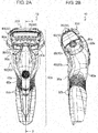
FIG. 2A is a front view illustrating a configuration of the electric shaver according to the exemplary embodiment of the present disclosure; -
FIG. 2B is a side view illustrating a configuration of the electric shaver according to the exemplary embodiment of the present disclosure; -
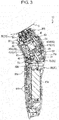
FIG. 3 is a sectional view taken along line 3-3 inFIG. 2A ; -
FIG. 4 is a perspective exploded view illustrating a configuration of the electric shaver according to the exemplary embodiment of the present disclosure; -
FIG. 5 is a perspective view illustrating a configuration of an outer blade block according to the exemplary embodiment of the present disclosure; -
FIG. 6 is a perspective exploded view illustrating a configuration of the outer blade block according to the exemplary embodiment of the present disclosure; -
FIG. 7 is a plan view illustrating a configuration of the outer blade block according to the exemplary embodiment of the present disclosure; -
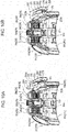
FIG. 8A is a sectional view taken alongline 8A-8A inFIG. 7 in a state where a rotating body of the outer blade block is positioned at a top dead center according to the exemplary embodiment of the present disclosure; -
FIG. 8B is a sectional view taken alongline 8B-8B inFIG. 7 in a state where the rotating body of the outer blade block is positioned at a bottom dead center according to the exemplary embodiment of the present disclosure; -
FIG. 9A is a sectional view taken alongline 9A-9A inFIG. 7 in a state where the rotating body of the outer blade block is positioned at the top dead center according to the exemplary embodiment of the present disclosure; -
FIG. 9B is a sectional view taken alongline 9B-9B inFIG. 7 in a state where the rotating body of the outer blade block is positioned at the bottom dead center according to the exemplary embodiment of the present disclosure; -
FIG. 10A is a sectional view taken alongline 10A-10A inFIG. 7 in a state where the rotating body of the outer blade block is positioned at the top dead center according to the exemplary embodiment of the present disclosure; -
FIG. 10B is a sectional view taken alongline 10B-10B inFIG. 7 in a state where the rotating body of the outer blade block is positioned at the bottom dead center according to the exemplary embodiment of the present disclosure; -
FIG. 11 is a view for describing a position relationship among an outer blade, an outer blade holding member, and the rotating body of the outer blade block according to the exemplary embodiment of the present disclosure; -
FIG. 12 is a view when a rotating body unit is viewed from outside according to the exemplary embodiment of the present disclosure; -
FIG. 13 is a view when the rotating body unit is viewed from inside according to the exemplary embodiment of the present disclosure; -
FIG. 14 is a perspective exploded view illustrating a configuration of the rotating body unit according to the exemplary embodiment of the present disclosure; -
FIG. 15A is a perspective view illustrating the rotating body unit which is partially broken away according to the exemplary embodiment of the present disclosure; -
FIG. 15B is a view when the rotating body unit which is partially broken away is viewed from inside according to the exemplary embodiment of the present disclosure; -
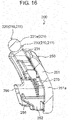
FIG. 16 is a sectional view taken along line 16-16 inFIG. 13 ; -
FIG. 17 is a sectional view taken along line 17-17 inFIG. 13 ; -
FIG. 18 is a view illustrating an enlarged G-portion inFIG. 17 ; -
FIG. 19 is a view illustrating the vicinity of a shaft of the rotating body in the partially enlarged rotating body unit according to the exemplary embodiment of the present disclosure; -
FIG. 20 is a perspective view illustrating a configuration of a rotator case according to the exemplary embodiment of the present disclosure; -
FIG. 21 is a perspective view illustrating a configuration of the outer blade holding member according to the exemplary embodiment of the present disclosure; -
FIG. 22 is a perspective view illustrating a state where the rotating body unit is mounted on the outer blade holding member according to the exemplary embodiment of the present disclosure; -
FIG. 23 is a perspective view illustrating the rotating body unit in a state where one end side of a rotator is moved downward according to the exemplary embodiment of the present disclosure; -
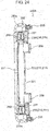
FIG. 24 is a plan view illustrating a configuration of a rotating body unit according to a first modification example of the exemplary embodiment of the present disclosure; -
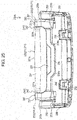
FIG. 25 is a view when a configuration of the rotating body unit is viewed from inside according to the first modification example of the exemplary embodiment of the present disclosure; -
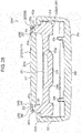
FIG. 26 is a side view illustrating a configuration of the rotating body unit according to the first modification example of the exemplary embodiment of the present disclosure; -
FIG. 27 is an enlarged plan view illustrating the vicinity of a shaft of a rotator in the rotating body unit according to the first modification example of the exemplary embodiment of the present disclosure; -
FIG. 28 is a sectional view taken along line 28-28 inFIG. 26 ; -
FIG. 29 is an enlarged view illustrating the vicinity of the shaft of the rotator inFIG. 28 ; -
FIG. 30 is a view when a configuration of a rotating body unit is viewed from inside according to a second modification example of the exemplary embodiment of the present disclosure; -
FIG. 31 is a side view illustrating a configuration of the rotating body unit according to the second modification example of the exemplary embodiment of the present disclosure; -
FIG. 32 is a sectional view taken along line 32-32 inFIG. 31 ; and -
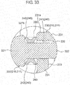
FIG. 33 is an enlarged view illustrating the vicinity of the shaft of the rotator inFIG. 32 . - An electric shaver according to an exemplary embodiment of the present disclosure includes a main body, an outer blade that is held by the main body in a state where a surface of the outer blade is exposed, and an inner blade that is disposed inside the outer blade so as to be movable relative to the outer blade.
- Furthermore, the electric shaver includes a rotator that has a rotating body disposed in the main body so as to extend in a moving direction of the inner blade, and a supporter disposed in the main body so as to rotatably support the rotating body.
- The rotator has an elastic body that enables the rotating body to rotate in a state where the rotating body is in contact with a skin, and that restrains the rotating body from vibrating in a state where the rotating body is not in contact with the skin.
- According to this configuration, in a state where the rotating body is not in contact with the skin, the elastic body can restrain the rotating body from vibrating, and can restrain an abnormal sound from being generated.
- On the other hand, the elastic body supports the rotating body so as to be rotatable in a state where the rotating body is in contact with the skin. Accordingly, when the outer blade is moved along the skin, it is possible to reduce a frictional force generated between the outer blade and the skin due to the rotation of the rotating body.
- A configuration may be adopted as follows. The rotating body has a shaft in both ends in an extending direction of the rotating body. The supporter has a bearing into which the shaft is inserted. The elastic body is a spring that biases the shaft toward an inner surface of the bearing. The spring supports the rotating body so as to be floatable.
- According to this configuration, the elastic body further has a function to bias the rotating body toward the supporter and a function to cause the rotating body to float to the main body. Therefore, the number of components can be reduced, and the configuration can be simplified.
- A configuration may be adopted in which a load applied to the rotating body by the spring is 1 time to 30 times the self-weight of the rotating body.
- According to this configuration, a force of the elastic body to support the rotating body is further ensured. It is possible to restrain a case where the rotating body becomes less likely to rotate due to an excessive frictional force applied to the rotating body.
- A configuration may be adopted in which the outer blade is supported by the main body so as to be floatable, and in which a floating direction of the rotating body intersects a floating direction of the outer blade.
- According to this configuration, a distance between the rotating body and the outer blade is further changed since a displacement height is changed. When the electric shaver is used, the skin can be stretched or squeezed by the rotating body and the outer blade.
- A configuration may be adopted in which the main body has a curve which protrudes outward, and in which a displacement trajectory of the rotating body is curved along the curve of the main body.
- According to this configuration, the main body having the rotator can be further miniaturized.
- A configuration may be adopted in which the rotator is disposed outside the main body.
- According to this configuration, even in a case where the electric shaver is used while the electric shaver touches the skin in a state where the main body of the electric shaver is tilted, a function of the rotator is fulfilled, thereby enabling a user to further feel more comfortable sensation in shaving.
- A configuration may be adopted in which the electric shaver further includes a rotator unit that has the rotator and a rotator case which holds the rotator, and in which the rotator unit is disposed in the main body via the rotator case.
- According to this configuration, the rotator is further integrally held by the rotator case. Therefore, while rigidity can be ensured, a size of the electric shaver can be reduced.
- A configuration may be adopted in which the rotator unit is mounted on the main body so as to be detachable from the main body.
- According to this configuration, for example, the electric shaver is used in a state where the rotator is not disposed in the main body. In this manner, the hair can be more reliably deeply shaved.
- Since the electric shaver is used in a state where the rotator is disposed in the main body, it is possible to reduce a frictional force generated between the outer blade and the skin.
- That is, a use state of the electric shaver can be diversified.
- A configuration may be adopted in which the inner blade is dis posed so as to be capable of linear reciprocating motion, in which the rot ator extends in a reciprocating direction of the inner blade, and is dispose d so as to be floatable to the main body, and in which a length of the ex tending direction of the rotator is greater than a reciprocating range of th e inner blade.
- Furthermore, the rotator also functions as a floater to float to the main body. A width in a reciprocating direction of the inner blade in a contact-available region where the floater can come into contact with the skin may be equal to or wider than a width in the reciprocating direction of the inner blade in a reciprocating region of the inner blade, or may be equal to or narrower than a width in the reciprocating direction of the inner blade in the main body.
- Furthermore, a configuration may be adopted in which one side end in the reciprocating direction of the inner blade in the contact-available region is positioned outside in the reciprocating direction of the inner blade, compared to one side end in the reciprocating direction of the inner blade in the reciprocating region of the inner blade.
- A configuration may be adopted in which the other side end in the reciprocating direction of the inner blade in the contact-available region is positioned outside in the reciprocating direction of the inner blade, compared to the other side end in the reciprocating direction of the inner blade in the reciprocating region of the inner blade.
- According to this configuration, while the rotator is further restrained from increasing in size, the rotator can more reliably disperse a pressing force applied to the skin which is generated by the linear reciprocating motion of the inner blade, and a frictional force applied to the skin.
- A configuration may be adopted in which the rotating body has a circular cross-sectional shape and a diameter in a thickest portion of the rotating body is at least 1.8 mm and at most 2.9 mm.
- According to this configuration, when the electric shaver is used, while a function of the rotator can be further fulfilled, discomfort caused by the rotating body coming into contact with the skin can be alleviated. Therefore, it is possible to obtain more comfortable sensation in shaving.
- A configuration may be adopted in which the rotator is disposed so as to be floatable to the main body, and in which a height of a top a t a top dead center of the rotator becomes lower than a height of a top o f the outer blade, and becomes higher than a height of a top of the main body.
- The height of the top at a bottom dead center of the rotator may become lower than the height of the top of the main body.
- In this manner, while the electric shaver can be restrained from having poor shaving performance, it is possible to obtain more comfortable sensation in shaving.
- A configuration may be adopted in which the top of the rotatin g body has an utmost top whose height becomes highest, and in which th e utmost top becomes higher than the top in both ends of the rotating bo dy and becomes higher than the top of the supporter.
- A configuration may be adopted in which the top in both ends of the rotating body becomes lower than the top of the supporter.
- According to this configuration, while the rotating body can be more reliably brought into contact with the skin, discomfort caused by the rotating body coming into contact with the skin can be alleviated. Therefore, it is possible to obtain more comfortable sensation in shaving.
- A configuration may be adopted in which the rotating body is supported in the supporter by a plurality of the elastic bodies which are elastically deformable independently of each other.
- According to this configuration, the rotating body can be further more reliably brought into contact with the skin having various irregular shapes. Therefore, it is possible to obtain more comfortable sensation in shaving.
- Hereinafter, an embodiment according to the present disclosure will be described with reference to the drawings.
- The embodiment does not limit the present disclosure.
- Hereinafter, description will be made in the following settings. A direction in which a plurality of outer blades are arrayed parallel to each other is referred to as front-back direction (shaving direction) X, a direction in which the respective outer blades extend is referred to as lateral direction Y, and a vertical direction in a state where an outer blade block (head unit) is disposed so that the outer blades face upward is referred to as vertical direction Z.
- A side on which a switch unit of the electric shaver is disposed is referred to as a front side in front-back direction X.
- A direction of the rotating body unit will also be described by using front-back direction X, lateral direction Y, and vertical direction Z which are described above. That is, in a state where the rotating body unit is mounted on an outer blade holding member (shaver body), directions which are coincident with front-back direction X, lateral direction Y, and vertical direction Z of the outer blade block (head unit) are respectively defined as front-back direction X, lateral direction Y, and vertical direction Z of the rotating body unit.
- As illustrated in
FIGS. 1A to FIG. 4 ,electric shaver 10 according to the present exemplary embodiment includesgripper 20 that hasholder 60a held by a hand, andhead unit 30 that hasblade unit 33 and that is supported bygripper 20. - In the present exemplary embodiment,
head unit 30 is swingable in lateral direction Y with respect togripper 20, around an axis ofshaft 40 extending in front-back direction X. - That is,
head unit 30 is supported bygripper 20 so as to be swingable aroundshaft 40. - As illustrated in
FIG. 4 ,gripper 20 includesgrip body 60 that hasholder 60a, andbase 70 that is fixed to one end side (upper side in vertical direction Z) ofgrip body 60 and that supportshead unit 30. -
Grip body 60 includesmain body housing 61 formed of a synthetic resin.Main body housing 61 is formed by joining a plurality of divided bodies with each other. A cavity is formed insidemain body housing 61 formed by joining the divided bodies with each other. The cavity internally accommodates various electrical components. - For example, the plurality of divided bodies can be joined with each other by using screws or by fitting the divided bodies to each other.
- In the present exemplary embodiment,
main body housing 61 is formed by joining the divided bodies such asfront housing 62,rear housing 63, andlower housing 64 with each other. A cavity formed betweenfront housing 62 andrear housing 63 accommodates power supply device (electrical component) 65 configured to includerechargeable battery 65c andcontrol board 65d (refer toFIGS. 3 and4 ). -
Main body housing 61 has pressing-type switch unit 65a which operates (turns on or off a power source of)electric shaver 10. In the present exemplary embodiment, pressing-type switch unit 65a is described as an example of the switch unit. However, as long as the power source can be turned on or off by the switch, a sliding-type switch or other switches may be used. - In the present exemplary embodiment,
switch unit 65a is formed on a front surface offront housing 62, that is, on a front surface (front face) ofelectric shaver 10. The front surface ofelectric shaver 10 means a surface on a side facing a user in a state where the user holdsholder 60a ofelectric shaver 10 when the user normally useselectric shaver 10. - Furthermore, the present exemplary embodiment adopts a configuration in which a
display 65b for displaying a charging state ofrechargeable battery 65c incorporated inmain body housing 61 is disposed in a lower portion ofswitch unit 65a infront housing 62. -
Trimmer unit 63a is disposed in a rear portion ofrear housing 63, that is, in a rear portion ofelectric shaver 10. A configuration without includingtrimmer unit 63a can also be adopted. -
Blade unit 33 includesouter blade 35 andinner blade 34 disposed inside outer blade 35 (lower side of outer blade 35). -
Outer blade 35 is disposed so as to be exposed upward fromhead unit 30. The exposed portion ofouter blade 35 serves as contact surface (surface) 35d which comes into contact with skin S of a user. - The user turns on the power source of
electric shaver 10. In a state whereinner blade 34 is moved relative to outer blade 35 (reciprocating in lateral direction Y,contact surface 35d ofouter blade 35 is moved whilecontact surface 35d is slid by touching skin S of the user. In this manner,inner blade 34 cuts hair introduced into a blade hole ofouter blade 35. - Next, a specific configuration of
head unit 30 andbase 70 for supportinghead unit 30 will be described. - As illustrated in
FIG. 4 ,head unit 30 includeshead unit body 80 mounted on base 70 (gripper 20), andouter blade block 90 mounted onhead unit body 80 so as to be detachable therefrom. -
Head unit body 80 includeshead case 81 that is open upward and that hasdrive mechanism accommodator 82 for accommodatingdrive mechanism 84, and head case cover 83 that covers the upward opening ofhead case 81 in a state wheredrive mechanism 84 is accommodated inside drive mechanism accommodator 82 (refer toFIGS. 3 and4 ). - In the present exemplary embodiment, a vibration-type linear actuator is described as an example of
drive mechanism 84. Without being limited to the vibration-type linear actuator,drive mechanism 84 may employ a known drive mechanism, for example, such as a drive mechanism configured to include a rotary motor and a conversion mechanism for converting a rotary motion into a linear reciprocating motion. -
Drive mechanism accommodator 82 is caused to function as a waterproof space (sealed space). It is preferable to restrain water used when the hair shaved byblade unit 33 andinner blade 34 are cleaned from entering the insidedrive mechanism accommodator 82. - On the other hand, as illustrated in
FIG. 4 ,outer blade block 90 includes substantially cylindrical (including a cylinder) outerblade holding member 91 on whichouter blade 35 is mounted so as to be vertically movable (floatable). - Outer
blade holding member 91 includes substantially cylindrical (including a cylinder)circumferential wall 91c on whichupper opening 91a andlower opening 91b are formed (refer toFIG. 6 ). - In the present exemplary embodiment,
circumferential wall 91c includesfront wall 91d andrear wall 91e which extend in lateral direction Y and vertical direction Z (on plane YZ), and a pair of right and leftside walls front wall 91d andrear wall 91e. Box-shapedouter blade cassette 92 which supportsouter blade 35 so as to be vertically movable is formed, andouter blade cassette 92 is mounted on outerblade holding member 91 by being accommodated therein from below. In this manner,outer blade 35 is mounted on outerblade holding member 91 so as to be vertically movable. - In the present exemplary embodiment, a plurality of
outer blades 35 arrayed parallel to each other in front-back direction X are supported byouter blade cassette 92. - Specifically,
outer blade 35 includes firstnet blade 35a, slitblade 35b, and secondnet blade 35c. Firstnet blade 35a, slitblade 35b, and secondnet blade 35c are disposed parallel to each other in front-back direction X (refer toFIG. 6 ). - In the present exemplary embodiment, respective outer blades 35 (first
net blade 35a, slitblade 35b, and secondnet blade 35c) are mounted on substantially frame-shapedouter blade frame 93 so as to be vertically movable independently of each other, thereby formingouter blade cassette 92. - As illustrated in
FIGS. 5 to 7 , both firstnet blade 35a and secondnet blade 35c are formed by being curved in an inverted U shape along front-back direction (short side direction) X so that the upper sides project in a side view (state whereouter blade 35 is viewed in lateral direction Y). Furthermore, firstnet blade 35a and secondnet blade 35c are formed by being slightly curved along lateral direction (longitudinal direction) Y so that the upper sides project in a front view (state whereouter blade 35 is viewed in front-back direction X). - In the present exemplary embodiment, first
net blade 35a and secondnet blade 35c are curved so that the upper sides project in a front view. However, it is not always essential that firstnet blade 35a and secondnet blade 35c are curved. - Multiple blade holes (not illustrated) are formed in each of first
net blade 35a and secondnet blade 35c. - As illustrated in
FIGS. 8A to 10B , slitblade 35b is formed by being folded in front-back direction (short side direction) X. Multiple slits (blade holes) extending from an upper flat wall to a side wall are drilled. - That is, in
slit blade 35b, multiple slits (blade holes) are formed while being divided by a crosspiece extending from the upper flat wall to the side wall and a crosspiece extending along longitudinal direction (lateral direction) Y in the lower portion of the side wall. - In the present exemplary embodiment, first
net blade 35a, secondnet blade 35c, and slitblade 35b which configureouter blade 35 are respectively mounted on a dedicated outer blade frame, thereby forming outer blade units. - The outer blade units respectively engage with outer blade frames 93 so as to be vertically movable independently of each other, thereby forming
outer blade cassette 92. - As illustrated in
FIG. 6 ,elastic pieces 94 respectively extend downward in both right and left ends ofouter blade frame 93. Through-holes 94a penetrating in the lateral direction are formed in a pair of right and leftelastic pieces 94. -
Recesses side walls blade holding member 91 in which both upper and lower ends are open, that is, in whichupper opening 91a andlower opening 91b are formed.Hooks respective recesses side walls - If
outer blade cassette 92 is inserted into outerblade holding member 91 fromlower opening 91b whileelastic pieces outer blade frame 93 pass throughrecesses blade holding member 91 engage with through-holes outer blade cassette 92 is mounted on outerblade holding member 91. - According to this configuration, sequentially from the front in front-back direction X, first
net blade 35a, slitblade 35b, and secondnet blade 35c are disposed in outerblade holding member 91 so as to be exposed upward. - In the present exemplary embodiment,
outer blade cassette 92 is mounted on outerblade holding member 91 so as to be detachable therefrom, and is also mounted onhead unit body 80 so as to be detachable therefrom. - In
inner blade 34, a dedicated inner blade is installed for firstnet blade 35a, secondnet blade 35c, and slitblade 35b which configureouter blade 35. Specifically, inverted U-shaped inner blades (firstinner blade 34a and secondinner blade 34c) which extend along respective curve shapes of firstnet blade 35a and secondnet blade 35c are disposed below (inside) firstnet blade 35a and secondnet blade 35c (refer toFIGS. 8A and 8B ). Slitinner blade 34b extending along a folded shape ofslit blade 35b is disposed below (inside) slitblade 35b. -
Inner blades 34 are mounted ondrive mechanism 84. Ifdrive mechanism 84 is driven,inner blades 34 respectively reciprocate in lateral direction (longitudinal direction) Y. - First
inner blade 34a, secondinner blade 34c, and slitinner blade 34b are mounted ondrive mechanism 84 so as to be vertically movable independently of each other. Respectiveinner blades 34 are disposed on the lower side of correspondingouter blade 35 so as to slide on the inner surface ofouter blade 35 wheninner blades 34 reciprocate in lateral direction (longitudinal direction) Y. - In this way, first
inner blade 34a, secondinner blade 34c, and slitinner blade 34b which are respectively disposed below (inside) firstnet blade 35a, secondnet blade 35c, and slitblade 35b are respectively moved relative to respective outer blades 35 (caused to reciprocate in lateral direction Y). In this manner, the hair introduced into the blade holes and slits of respectiveouter blades 35 can be cut by a plurality ofouter blades 35 in cooperation withinner blades 34 respectively corresponding to the plurality ofouter blades 35. - In the present exemplary embodiment, slit
inner blade 34b is mounted onouter blade cassette 92 so as to be capable of reciprocating with respect toslit blade 35b. -
Release button 80a (refer toFIGS. 2A and 2B ) is disposed in both right and left ends ofhead unit body 80 so as to be capable of projecting in lateral directionY. Release button 80a is pressed inward, thereby releasingouter blade block 90 mounted onhead unit body 80. - When
outer blade block 90 is mounted onhead unit body 80, a space which can collect the hair shaved byblade unit 33 is formed in an upper portion ofhead case cover 83. -
Window 80c through which the space communicates with an external space is formed in a front portion of head unit 30 (refer toFIG. 2A ).Window 80c functions as an introduction port for introducing water into the space when the hair collected in the space is cleaned, and as a discharge port for discharging the hair and the water inside the space. - A shutter (lid) 80b which covers
window 80c so as to be openable or closeable is disposed in the front portion ofhead unit 30 so as to be slidable in the vertical direction. - In the present exemplary embodiment, as illustrated in
FIGS. 3 and4 ,gripper 20 andhead unit 30 are connected to each other viaconnection member 41. - That is, one end (lower side) of
connection member 41 is connected to gripper 20, and the other end (upper side) is connected to headunit 30. - In this case, a configuration is adopted in which
connection member 41 moves relative togripper 20 in an intersecting direction (direction along plane YZ) intersecting the extending direction (front-back direction X) ofshaft 40. -
Connection member 41 is connected to headunit 30 viashaft 40.Head unit 30 laterally swings with respect toconnection member 41 aroundshaft 40. - In the present exemplary embodiment,
connection member 41 is connected toholder member 72 ofbase 70 configuring a portion ofgripper 20, and is also connected to headcase 81 configuring a portion of head unit 30 (refer toFIGS. 5 to 8B ). - Furthermore,
connection member 41 includesfront connection member 41A andrear connection member 41B formed separate fromfront connection member 41A.Front connection member 41A andrear connection member 41B are respectively connected to holder member 72 (gripper 20) and head case 81 (head unit 30). - In the present exemplary embodiment,
shaft 40 formed separate fromhead unit 30 andconnection member 41 is used.Shaft 40 includesfront shaft 40A andrear shaft 40B formed separate fromfront shaft 40A. -
Front connection member 41A is connected to a front portion of head case 81 (head unit 30) viafront shaft 40A, andrear connection member 41B is connected to a rear portion of head case 81 (head unit 30) viarear shaft 40B (refer toFIG. 3 ). -
Base 70 includesbase body 71 fixed to one end side (upper side in vertical direction Z) ofgrip body 60, andholder member 72 which is mounted onbase body 71 and to which connection member 41 (front connection member 41A andrear connection member 41B) is connected. -
Base body 71 is mounted ongrip body 60. In a state where the longitudinal direction ofgrip body 60 is positioned to be the vertical direction, when viewed in lateral direction Y,base body 71 has a triangular shape in which the upper portion ofbase body 71 serves as a tilting piece tilting forward and downward.Holder member 72 is mounted on the upper portion ofbase body 71, that is, on tiltingsurface 71a tilting forward and downward (refer toFIG. 4 ). - In the present exemplary embodiment, a direction perpendicular to tilting
surface 71a is coincident with vertical direction Z which is the vertical direction ofhead unit 30. Therefore, in the present exemplary embodiment,head unit 30 is mounted ongrip body 60 so that the upper portion ofhead unit 30 tilts forward and downward when viewed in lateral direction Y, in a state where the longitudinal direction ofgrip body 60 becomes the vertical direction (refer toFIG. 2B ). -
Holder member 72 includesloader 73 loaded on tiltingsurface 71a ofbase body 71. Mountingpieces 73a extending downward and rearward are respectively formed in both ends in lateral direction Y ofloader 73. - Right and left mounting
pieces 73a are fixed tobase body 71 byscrews 73b, thereby mountingholder member 72 on base body 71 (refer toFIG. 4 ). - As illustrated in
FIG. 4 ,holder member 72 includesfront connection piece 74 which is connected to a front end ofloader 73 and which extends forward and upward, andrear connection piece 75 which is connected to a rear end ofloader 73 and which extends rearward and upward. -
Front connection piece 74 andfront connection member 41A are connected to each other, andrear connection piece 75 andrear connection member 41B are connected to each other (refer toFIG. 4 ). - Here, in the present exemplary embodiment, substantially cylindrical (including a cylinder) projection 41aA projecting forward is formed at a position shifted from
front shaft 40A, which is immediately belowfront shaft 40A infront connection member 41A. - Substantially circular (including a circular shape)
insertion hole 74a into which projection 41aA is inserted is formed infront connection piece 74. - An inner diameter of
insertion hole 74a is configured to be larger than an outer diameter of projection 41aA. In this manner, in a state where connection member 41 (front connection member 41A) is connected to gripper 20 (holder member 72), when viewed in front-back direction X (extending direction of shaft 40), substantially annular (including an annular shape)clearance 42 which allows connection member 41 (front connection member 41A) to move relative to gripper 20 (holder member 72) in the intersecting direction (direction along plane YZ) is formed between connection member 41 (front connection member 41A) and gripper 20 (holder member 72). - O-ring (elastic member) 43 is disposed in substantially
annular clearance 42. In this manner, connection member 41 (front connection member 41A) is connected to gripper 20 (holder member 72) via O-ring 43. - According to this configuration, while
connection member 41 is allowed to move relative to gripper 20 in the intersecting direction, rattling ofconnection member 41 can be more reliably restrained. - According to the configuration, in a state where a central axis of
front shaft 40A and a central axis ofrear shaft 40B are positioned on a substantially straight line (including a straight line),head unit 30 is supported bygripper 20. Accordingly,head unit 30 is enabled to more smoothly swing with respect togripper 20. - In the present exemplary embodiment,
wiring tube 51 is fixed to a lower portion ofhead case 81 by wiringtube holding member 52. Wiringtube holding member 52 andbase body 71 are connected to each other bytension spring 53. In this way, wiringtube holding member 52 andbase body 71 are connected to each other bytension spring 53, thereby causinghead unit 30 to return to a neutral position. -
Electric shaver 10 includes shaver body (main body) 100,outer blade 35 held byshaver body 100 in a state where contact surface (surface) 35d is exposed, andinner blade 34 disposed insideouter blade 35 so as to be movable relative toouter blade 35. - In the present exemplary embodiment, among components configuring
electric shaver 10, those which are configured to includegripper 20 andhead unit 30 other thanblade unit 33 serve asshaver body 100. -
Shaver body 100 includesdrive body 110 which drives mountedinner blade 34, and outerblade holding member 91 which holdsouter blade 35 in a state where contact surface (surface) 35d is exposed. - Outer
blade holding member 91 is mounted ondrive body 110 so as to be detachable therefrom. - In the present exemplary embodiment,
outer blade block 90 including outerblade holding member 91 is mounted onhead unit body 80 so as to be detachable therefrom. Accordingly, among components configuringelectric shaver 10, those which are configured to include components remaining by detachingouter blade block 90 andinner blade 34 serve asdrive body 110. - Therefore, outer
blade holding member 91 is mounted ondrive body 110 so as to be detachable therefrom viaouter blade frame 93 ofouter blade cassette 92. - In this way, in the present exemplary embodiment,
shaver body 100 includesdrive body 110, outerblade holding member 91, andouter blade frame 93. - In the present exemplary embodiment, rotating
body unit 200 is disposed in outerblade holding member 91 ofshaver body 100. In this manner, whenouter blade 35 is moved along skin S, rotatingbody 220 ofrotating body unit 200 rotates while coming into contact with skin S. - According to this configuration, when
outer blade 35 is moved along skin S, it is possible to reduce a frictional force generated betweenouter blade 35 and skin S. Therefore, the hair can be more comfortably and more effectively shaved. - Next, a specific configuration of
rotating body unit 200 and a structure of mountingrotating body unit 200 onshaver body 100 will be described. -
Rotating body unit 200 described above is one of components configuringelectric shaver 10. However, hereinafter, an example will be described in which rotatingbody unit 200 does not configureshaver body 100. - That is, the above description of "among components configuring
electric shaver 10, those which are configured to includegripper 20 andhead unit 30 other thanblade unit 33 serve asshaver body 100" means that among components configuringelectric shaver 10, those which are configured to includegripper 20 and head unit 30 (however,blade unit 33 androtating body unit 200 are excluded) configureshaver body 100. - As illustrated in
FIG. 12 , rotatingbody unit 200 according to the present exemplary embodiment is formed in such a way that rotatorcase 250 holds rotator 210 formed bysupporter 230 supportingrotating body 220 so as to be rotatable. - That is,
rotating body unit 200 includes rotator 210 androtator case 250 which integrally holds rotator 210. - Rotator 210 has rotating
body 220 mounted onshaver body 100 so as to be rotatable, andsupporter 230 which supportsrotating body 220 so as to be rotatable. - As illustrated in
FIG. 14 , rotatingbody 220 includesmain body 221 which extends in lateral direction Y andshafts 222 which project outward in lateral direction Y from each of both ends 221b and 221b ofmain body 221. It is preferable thatrotating body 220 is formed of a material which is not easily deformed, such as resins, metal, and ceramics. - In the present exemplary embodiment,
main body 221 has a substantially circular (including a circular shape) cross-sectional shape. An upper side ridge line in a front view (state wheremain body 221 is viewed in front-back direction X) configures top T6. Top T6 is formed by being curved along lateral direction (longitudinal direction of main body 221) Y so that the upper side projects in a front view (refer toFIG. 12 ). - That is,
main body 221 is formed so that the diameter decreases from the center toward both ends in lateral direction Y In the present exemplary embodiment, in both ends 221b and 221b ofmain body 221, the diameter increases outward in lateral direction Y. However, a height of top T6 in the center ofmain body 221 is configured to become higher than a height of top T6 in both ends 221b and 221b ofmain body 221. - In this way, in the present exemplary embodiment,
main body 221 hasthickest portion 221a in which a center in lateral direction Y is thickest (diameter is maximized). Top T6 inthickest portion 221a is utmost top T7 (refer toFIG. 12 ). - That is, top T6 of
rotating body 220 has utmost top T7 whose height is highest at the center in lateral direction Y. Height T7a of utmost top T7 is higher than height T8a of top T8 in each of both ends 221b and 221b of rotating body 220 (refer toFIG. 19 ). - If the outer diameter of
rotating body 220 is too large (for example, the diameter inthickest portion 221a is larger than 2.9 mm), there is a possibility that a user may feel discomfort on the skin when usingelectric shaver 10. On the other hand, if the outer diameter ofrotating body 220 is too small (for example, the diameter inthickest portion 221a is smaller than 1.8 mm), rotatingbody 220 is less likely to rotate. - Therefore, when rotating
body 220 is formed, it is preferable to adopt a configuration in which the diameter in thickest portion (thickest portion of rotating body 220) 221a is 1.8 mm to 2.9 mm. - As described above, rotating
body 220 configured in this way is supported by support member (supporter) 230 so as to be rotatable. - As illustrated in
FIG. 14 ,supporter 230 includes a pair ofbearings connectors 234 connected to a lower end of the pair ofbearings - The pair of
bearings holes shafts rotating body 220 are inserted. - Bearing holes 232 and 232 are formed inside the pair of
bearings - An opening diameter of the pair of
bearings shafts - Therefore, in a state where
rotating body 220 is supported bysupporter 230 after respectively inserting right and leftshafts 222 into the pair of bearingholes 232,clearance 241 is formed betweencircumferential surface 222a ofshaft 222 andinner surface 232a of bearing hole 232 (refer toFIG. 18 ). - A configuration is adopted in which
clearance 242 is also formed betweenmain body 221 ofrotating body 220 andbearings FIG. 19 ). - In this way, in the present exemplary embodiment, rotating
body 220 is supported bysupporter 230 in a state where clearance 240 (clearance 241 and clearance 242) is formed betweenrotating body 220 andsupporter 230. - Since
clearance 240 is formed,rotating body 220 smoothly rotates with respect tosupporter 230. - In the present exemplary embodiment, curves 234a and 234a are formed in
connector 234 so thatconnector 234 can be elastically deformed.Connector 234 is elastically deformed fromcurves bearings - In a state where the pair of
bearings shafts holes body 220 can be mounted onsupporter 230. - In a state where
rotating body 220 is mounted onsupporter 230, height T7a of utmost top T7 ofrotating body 220 is configured to be higher than height T9a of top T9 ofsupporter 230. Height T8a of top T8 in both ends 221b and 221b ofrotating body 220 is configured to be lower than height T9a of top T9 of supporter 230 (refer toFIG. 19 ). - In the present exemplary embodiment,
upper end surfaces bearings supporter 230. - In this way, rotating
body 220 is mounted onsupporter 230 so as to be rotatable, thereby forming rotator 210. - Rotator 210 is held integrally with
rotator case 250, thereby formingrotating body unit 200. - As illustrated in
FIG. 14 ,rotator case 250 includesrear wall 251 which covers rotator 210 from rear when rotatingbody unit 200 is mounted on outer blade holding member 91 (shaver body 100).Bottom wall 252 is connected to a lower portion ofrear wall 251 so as to extend forward. A pair ofside walls rear wall 251 so as to extend forward. -
Accommodation space 254 which accommodates rotator 210 is formed byrear wall 251,bottom wall 252, and the pair ofside walls - Here, in the present exemplary embodiment, rotator 210 has floater 211 which floats to rotator case 250 (shaver body 100).
- Specifically, an entire body of rotator 210 including
rotating body 220 is configured to be supported by coil spring (elastic body) 270 so as to be floatable torotator case 250, thereby forming floater 211. - In this way, in the present exemplary embodiment, the entire body of rotator 210 configures floater 211 which floats to rotator case 250 (shaver body 100). A configuration can also be adopted in which a portion of rotator 210 serves as floater 211.
- Next, a structure will be described in detail in which rotator 210 floats to rotator case 250 (shaver body 100).
- First, in the present exemplary embodiment, spring insertion holes 233 and 233 extending in substantially vertical direction Z are respectively formed in the pair of
bearings holes 232 and 232 (refer toFIG. 18 ). - A configuration is adopted in which coil springs (elastic bodies) 270 and 270 are inserted from below into respective spring insertion holes 233 and 233 so as to bring
upper ends circumferential surfaces shafts - On the other hand, lower ends 272 and 272 of coil springs (elastic bodies) 270 and 270 are supported by
bottom wall 252 ofrotator case 250 viaspring receiving members 260 and 260 (refer toFIG. 17 ). - Specifically, as illustrated in
FIG. 14 ,spring receiving member 260 includesspring receiving body 261 in which spring receivingprojection 261a is formed at the center, and a pair ofhooks spring receiving body 261. -
Spring receiving member 260 is inserted from below intoinsertion hole 257 formed onbottom wall 252, and the pair ofhooks bottom wall 252, thereby mounting,spring receiving member 260 onbottom wall 252. - In this case,
spring receiving projection 261a is inserted intolower end 272 of coil spring (elastic body) 270. In this manner, coil spring (elastic body) 270 is supported bybottom wall 252 ofrotator case 250 viaspring receiving member 260. - Furthermore, in the present exemplary embodiment, guide
projections bearings Y. Guide projections guide grooves rotator case 250 so as to be respectively slidable (refer toFIGS. 10A and 10B ). - In the present exemplary embodiment,
top walls front walls side walls rotator case 250, thereby formingguide grooves - In this way, guide
projections guide grooves guide projections guide grooves - The present exemplary embodiment adopts a configuration which regulates rotator 210 (floater 211) floating to
rotator case 250 in an upward direction by briningguide projections top walls - On the other hand, rotator 210 (floater 211) floating to
rotator case 250 in a downward direction is regulated by bringingconnector 234 ofsupporter 230 into contact withregulation projections bottom wall 252 of rotator case 250 (refer toFIG. 13 ). - For example, rotating
body unit 200 configured in this way can be assembled using the following method. -
Connector 234 is elastically deformed fromcurves bearings - In a state where the pair of
bearings shafts holes - In this manner, rotating
body 220 is mounted onsupporter 230. - Next, guide
projections supporter 230 on which rotatingbody 220 is mounted are inserted intoguide grooves rotator case 250. - In this state, two coil springs (elastic bodies) 270 and 270 are inserted from below into
insertion holes bottom wall 252, and are inserted into spring insertion holes 233 and 233 formed inbearings - Thereafter, in a state where
spring receiving projection 261a is inserted intolower end 272 of coil spring (elastic body) 270,spring receiving member 260 is inserted from below intoinsertion hole 257 formed onbottom wall 252, and the pair ofhooks bottom wall 252. - In this way, rotating
body unit 200 is formed in which rotator 210 (floater 211) is held byrotator case 250 so as to be floatable. - In this case, in a state of being contracted than a natural state (free state), coil spring (elastic body) 270 which supports floater 211 so as to be floatable to
rotator case 250 is disposed between rotator 210 (floater 211) androtator case 250. - Therefore, rotating
body 220 is always biased toward supporter 230 (biased upward) by coil spring (elastic body) 270. That is, in a state whererotating body 220 is not in contact with skin S, rotatingbody 220 is supported byupper end 271 of coil spring (elastic body) 270 in a state wherecircumferential surface 222a ofshaft 222 is in contact withinner surface 232a of bearinghole 232. In this manner, rotatingbody 220 is restrained from vibrating. - When rotating
body 220 is brought into contact with skin S, in rotatingbody 220,shaft 222 moves downward relative to bearing 231 against a biasing force of coil spring (elastic body) 270. In this manner, contact betweencircumferential surface 222a ofshaft 222 andinner surface 232a of bearinghole 232 is released. This configuration allowsrotating body 220 to rotate. - In this way, the present exemplary embodiment adopts a configuration in which
rotating body 220 is supported insupporter 230 by coil spring (elastic body) 270 which restrainsrotating body 220 from vibrating in a state whererotating body 220 is not in contact with skin S while allowingrotating body 220 to rotate in a state whererotating body 220 is in contact with skin S. - In this case, it is preferable that a load applied to
rotating body 220 by coil spring (elastic body) 270 is 1 time to 30 times the self-weight ofrotating body 220. - If the load applied to
rotating body 220 is smaller than the self-weight ofrotating body 220, the rotation and the vibrations ofrotating body 220 cannot be reduced by coil spring (elastic body) 270, thereby causing a possibility that abnormal sounds and vibrations may be generated. On the other hand, the load applied torotating body 220 is greater than 30 times the self-weight ofrotating body 220, an excessive frictional force is applied torotating body 220. Consequently, rotatingbody 220 cannot be smoothly rotated. - In order to smoothly rotate
rotating body 220 in a state whererotating body 220 is in contact with skin S, it is preferable to adopt a configuration in which contact betweenupper end 271 of coil spring (elastic body) 270 andcircumferential surface 222a ofshaft 222 is line contact or point contact. The present exemplary embodiment adopts a configuration in whichupper end 271 of coil spring (elastic body) 270 comes into point contact withcircumferential surface 222a ofshaft 222 at one point or two points. In order to bringupper end 271 into line contact or point contact withcircumferential surface 222a ofshaft 222, it is preferable that the elastic body is formed using a hard material. - Top T1 of rotator 210 (floater 211) is set so as to float between height T1a at a top dead center and height T1b at a bottom dead center (refer to
FIG. 11 ). - While height T1a at the top dead center of top T1 is configured to be higher than height T4a of top (utmost top) T4 in both ends of
rotator case 250, height T1b at the bottom dead center of top T1 is configured to be lower than height T4a of top (utmost top: upper end surface oftop wall 253a) T4 in both ends ofrotator case 250. - Furthermore, in the present exemplary embodiment, the center in lateral direction Y of
rear wall 251 is formed so as to be recessed downward. Height T1b at the bottom dead center of top T1 is configured to be higher than height T5a of top T5 at the center ofrotator case 250. -
Rotating body unit 200 having this configuration is mounted on outer blade holding member 91 (shaver body 100). - Specifically, engagement hooks 256 respectively formed on
bottom wall 252 and the pair ofside walls rotator case 250 are caused to engage withengagement grooves 91j formed onrear wall 91e of outerblade holding member 91, thereby mountingrotating body unit 200 on outer blade holding member 91 (shaver body 100) from outside. - In this way, in the present exemplary embodiment, rotator 210 is integrally held by
rotator case 250, and is disposed in outer blade holding member 91 (shaver body 100) viarotator case 250. - A configuration may be adopted in which rotating
body unit 200 is mounted on outer blade holding member 91 (shaver body 100) so as to be detachable therefrom. -
Rotating body unit 200 is mounted onrear wall 91e of outerblade holding member 91 from outside. In this manner, rotatingbody unit 200 is mounted on the outside of outer blade holding member 91 (shaver body 100) in a direction in which the plurality ofouter blades 35 are arrayed parallel to each other (front-back direction X). - Therefore, rotating
body 220 is disposed so as to extend in the reciprocating direction (lateral direction Y) ofinner blade 34 disposed so as to be capable of linear reciprocating motion in lateral direction Y (refer toFIGS. 5 and7 ). - In the present exemplary embodiment, in rotator 210,
upper end surfaces bearings main body 221 ofrotating body 220 serve as contact-available region R1 in which floater 211 can come into contact with skin S (refer toFIG. 5 ). - Width W1 in lateral direction (reciprocating direction of inner blade 34) Y in contact-available region R1 is configured to be equal to or wider than width W4 in lateral direction (reciprocating direction of inner blade 34) Y of second
inner blade 34c (inner blade 34), and is configured to be equal to or wider than width W2 in lateral direction (reciprocating direction of inner blade 34) Y in reciprocating region R2 of secondinner blade 34c (inner blade 34). - Furthermore, width W1 in lateral direction (reciprocating direction of inner blade 34) Y in contact-available region R1 is configured to be equal to or narrower than width (maximum width) W3 in lateral direction (reciprocating direction of inner blade 34) Y in outer blade holding member 91 (shaver body 100).
- End portion R1a on one side in lateral direction (reciprocating direction of inner blade 34) Y in contact-available region R1 is configured to be positioned outside in lateral direction (reciprocating direction of inner blade 34) Y, compared to end portion R2a on one side in lateral direction (reciprocating direction of inner blade 34) Y in reciprocating region R2 of second
inner blade 34c (inner blade 34). Furthermore, end portion R1b on the other side in lateral direction (reciprocating direction of inner blade 34) Y in contact-available region R1 is configured to be positioned outside in lateral direction (reciprocating direction of inner blade 34) Y, compared to end portion R2b on the other side in lateral direction (reciprocating direction of inner blade 34) Y in reciprocating region R2 of secondinner blade 34c (inner blade 34). - That is,
rotating body unit 200 is mounted on outer blade holding member 91 (shaver body 100) so that overall secondinner blade 34c (inner blade 34) overlaps contact-available region R1 (upper end surfaces inner blade 34c (inner blade 34) is viewed in front-back direction X, even if secondinner blade 34c (inner blade 34) performing linear reciprocating motion is located at any position. - In this way, an arrangement relationship between contact-available region R1 and inner blade 34 (in the present exemplary embodiment, second
inner blade 34c) adjacent thereto in front-back direction X is specified. In this manner, the hair can be more comfortably and more effectively shaved. - In the present exemplary embodiment, as illustrated in
FIG. 11 , in a state whererotating body unit 200 is mounted on outer blade holding member 91 (shaver body 100), height T1a at the top dead center of top T1 of rotator 210 (floater 211) is configured to be lower than height T2a of top T2 at the top dead center of secondnet blade 35c (outer blade 35). In this case, it is preferable to adopt a configuration in which a difference between height T2a and height T1a is greater than 0 mm, and is equal to or smaller than 2 mm. - If a configuration is adopted in which the difference between height T2a and height T1a is equal to or greater than a blade thickness of
outer blade 35, the top ofinner blade 34 can be located at a position higher than height T1a. Accordingly, when the hair is cut byinner blade 34 andouter blade 35, it is possible to restrain a possibility that the hair may not be deeply shaved since rotator 210 (floater 211) interferes with the skin. - Furthermore, height T1b at the bottom dead center of top T1 is configured to be lower than height T2b of top T2 at the bottom dead center of second
net blade 35c (outer blade 35). - Height T1b at the bottom dead center of top T1 is configured to be lower than height T3a of top T3 of outer blade holding member 91 (shaver body 100).
- Height T2b at the bottom dead center of top T2 is configured to be higher than height T4a of top (utmost top: upper end surface of
top wall 253a) T4 in both ends ofrotator case 250, and is configured to be higher than height T3a of top T3 of outer blade holding member 91 (shaver body 100). - Furthermore, the present exemplary embodiment adopts a configuration in which floating direction D2 of rotating body 220 (floater 211) intersects floating direction D1 (vertical direction Z) of outer blade 35 (refer to
FIG. 8A ). - Specifically, floating direction D2 of rotating body 220 (floater 211) is set so that rotating body 220 (floater 211) moves in a direction away from outer blade 35 (rearward in front-back direction X), when rotating body 220 (floater 211) floats downward. In the present exemplary embodiment, floating direction D2 is configured to be curved so as to project outward (rearward).
- Specifically,
curve 91i which projects outward (rearward) is formed onrear wall 91e of outer blade holding member 91 (shaver body 100), andcurve 251a which is curved alongcurve 91i is formed onrear wall 251 ofrotator case 250. - Furthermore, guide
grooves rotator case 250 are also curved alongcurve 91i. - If rotating body 220 (floater 211) is caused to float, guide
projection 235 moves alongguide groove 255. A trajectory drawn in this case is displacement trajectory P2 ofguide projection 235, and displacement trajectory P2 is curved alongcurve 91i (refer toFIG. 11 ). - As
guide projection 235 is displaced, rotating body 220 (floater 211) is also displaced. A trajectory drawn by rotating body 220 (floater 211) is displacement trajectory P1 of rotatingbody 220. Similarly to displacement trajectory P2, displacement trajectory P1 of rotatingbody 220 is curved alongcurve 91i. A direction extending along displacement trajectory P1 of rotatingbody 220 is floating direction D2. - According to this configuration, if rotating body 220 (floater 211) is caused to float (move) from above to below, rotating body 220 (floater 211) is displaced so that a distance between rotating body 220 (floater 211) and second
net blade 35c (outer blade 35) increases from L1 to L2 (refer toFIGS. 8A and 8B ). - However, in the present exemplary embodiment, floating direction D2 is curved along
curve 91i. Accordingly, as rotating body 220 (floater 211) further moves downward, a displacement amount of rotating body 220 (floater 211) displaced from secondnet blade 35c (outer blade 35) decreases. - In the present exemplary embodiment, rotating
body 220 is supported bysupporter 230 using the plurality of (two) coil springs (elastic bodies) 270 and 270 which are elastically deformable independently of each other. - According to this configuration, rotator 210 (floater 211) can be displaced with a posture different from that of blade unit 33 (
outer blade 35 and inner blade 34) (refer toFIG. 23 ). - Next, modification examples of the rotating body unit will be described.
- As the rotating body unit, it is possible to use
rotating body unit 200A illustrated inFIGS. 24 to 29 , for example. - Basically, rotating
body unit 200A has a configuration which is substantially the same as that ofrotating body unit 200 described above.Rotating body unit 200A adopts a configuration in which rotator 210 formed in such a way thatrotating body 220 is rotatably supported insupporter 230 is integrally held byrotator case 250. -
Rotating body unit 200A is also configured to be supported insupporter 230 byelastic body 280 which restrainsrotating body 220 from vibrating in a state whererotating body 220 is not in contact with skin S while allowsrotating body 220 to rotate in a state whererotating body 220 is in contact with skin S. - Specifically, substantially U-shaped (including U-shape) slit 281 is formed in the pair of
bearings elastic piece 282 which is elastically deformable. - In this way, in rotating
body unit 200A,elastic body 280 is integrally formed insupporter 230. - According to this configuration, it is possible to reduce the number of components.
-
Projections shafts elastic piece 282.Circumferential surfaces shafts projections circumferential surface 222a ofshaft 222 into contact withinner surface 232a of bearinghole 232. - As another example of the rotating body unit, it is also possible to use
rotating body unit 200B illustrated inFIGS. 30 to 33 , for example. - Basically, rotating
body unit 200B also has a configuration which is substantially the same as that ofrotating body unit 200 described above.Rotating body unit 200B adopts a configuration in which rotator 210 formed in such a way thatrotating body 220 is rotatably supported insupporter 230 is integrally held byrotator case 250. -
Rotating body unit 200B is also configured to be supported insupporter 230 byelastic body 290 which restrainsrotating body 220 from vibrating in a state whererotating body 220 is not in contact with skin S while allowsrotating body 220 to rotate in a state whererotating body 220 is in contact with skin S. - Specifically, a soft elastic body (elastic body 290) such as rubber or cushion is interposed in
clearance 242 formed betweenmain body 221 ofrotating body 220 andbearings supporter 230. In this manner, rotatingbody unit 200B is configured to be capable of restrainingrotating body 220 from vibrating in a state whererotating body 220 is not in contact with skin S while allowsrotating body 220 to rotate in a state whererotating body 220 is in contact with skin S. - In this way, while strength of
supporter 230 can be reliably ensured, it is possible to realize an elastic support structure of a space-saving and compact rotating body. - As described above,
electric shaver 10 according to the present exemplary embodiment includesshaver body 100,outer blade 35 held byshaver body 100 in a state where contact surface (surface) 35d is exposed, andinner blade 34 disposed insideouter blade 35 so as to be movable relative toouter blade 35. - Furthermore,
electric shaver 10 includes rotator 210 that has rotatingbody 220 mounted onshaver body 100 so as to be rotatable, andsupporter 230 which supportsrotating body 220 so as to be rotatable. -
Rotating body 220 is supported insupporter 230 by the elastic body which restrainsrotating body 220 from vibrating in a state whererotating body 220 is not in contact with skin S while allowsrotating body 220 to rotate in a state whererotating body 220 is in contact with skin S. As the elastic body, for example, at least any one ofcoil spring 270,elastic body 280, and softelastic body 290 is used. - According to this configuration, the elastic body restrains rotating
body 220 from vibrating in a state whererotating body 220 is not in contact with skin S. Accordingly, it is possible to restrain an abnormal sound from being generated. - On the other hand, elastic body supports rotating
body 220 so as to be rotatable in a state whererotating body 220 is in contact with skin S. Accordingly, whenouter blade 35 is moved along skin S, rotatingbody 220 is rotated, thereby reducing a frictional force generated betweenouter blade 35 and skin S. - In this way, according to the present embodiment, it is possible to obtain
electric shaver 10 which can restrain abnormal sounds and vibrations from being generated while more comfortably and more effectively cut the hair. - A configuration may be adopted in which the elastic body has
coil spring 270 for biasingrotating body 220 towardsupporter 230, and in whichcoil spring 270supports rotating body 220 so as to be floatable. - In this way,
coil spring 270 has a function to biasrotating body 220 towardsupporter 230, and a function to causerotating body 220 to float toshaver body 100. Accordingly, it is possible to reduce the number of components, and it is possible to simplify the configuration. - Since
coil spring 270 is used, while the elastic body is allowed to have a small size, a load can be adjusted. Therefore, it is possible to obtain high reliability in contacting and high reliability in pressing. - A load applied to
rotating body 220 bycoil spring 270 may be 1 time to 30 times the self-weight ofrotating body 220. - In this manner, a force of
coil spring 270 to supportrotating body 220 is ensured. It is possible to restrain a case whererotating body 220 becomes less likely to rotate due to an excessive frictional force applied torotating body 220. - A configuration may be adopted in which
outer blade 35 is supported byshaver body 100 so as to be floatable, and in which floating direction D2 ofrotating body 220 intersects floating direction D1 ofouter blade 35. - In this manner, a distance between
rotating body 220 andouter blade 35 is changed since a displacement height is changed. Whenelectric shaver 10 is used, the skin can be stretched or squeezed by rotatingbody 220 andouter blade 35. As a result, the hair can be more easily and deeply shaved. - A configuration may be adopted in which
shaver body 100 hascurve 91i which protrudes outward, and in which displacement trajectory P1 of rotatingbody 220 is curved alongcurve 91i ofshaver body 100. - In this manner,
shaver body 100 having rotator 210 can be miniaturized. - A configuration may be adopted in which rotator 210 is disposed outside
shaver body 100. - In this way, rotator 210 is disposed outside
shaver body 100 which is most likely to touch the skin. Accordingly, even in a case whereshaver body 100 in a tilting state is used while touching skin S, a function of rotator 210 can be fulfilled. Therefore, it is possible to obtain more comfortable sensation in shaving. - A configuration may be adopted in which rotator 210 is integrally held by
rotator case 250, and in which rotator 210 is disposed inshaver body 100 viarotator case 250. - In this way, rotator 210 is integrally held by
rotator case 250. Therefore, while rigidity can be ensured, a size ofshaver body 100 can be reduced. - A configuration may be adopted in which
rotator case 250 is mounted onshaver body 100 so as to be detachable therefrom. - In this way, rotator 210 is used in a state where rotator 210 is not disposed in
shaver body 100. In this manner, the hair can be more reliably deeply shaved. Rotator 210 is used in a state where rotator 210 is disposed inshaver body 100. In this manner, it is possible to reduce a frictional force generated betweenouter blade 35 and skin S. That is, a use state ofelectric shaver 10 can be diversified. - A plurality of types are prepared for the rotating body unit. Therefore, in accordance with use of the rotating body unit,
electric shaver 10 can be properly used. - A configuration may be adopted in which
inner blade 34 is disposed so as to be capable of linear reciprocating motion with respect toouter blade 35, and in whichrotating body 220 is disposed so as to extend in the reciprocating direction (lateral direction Y) ofinner blade 34. A configuration may be adopted in which rotator 210 has floater 211 which floats toshaver body 100. - A configuration may be adopted in which width W1 in the reciprocating direction of
inner blade 34 in contact-available region R1 in which floater 211 can come into contact with skin S is equal to or wider than width W2 in the reciprocating direction ofinner blade 34 in reciprocating region R2 ofinner blade 34, and is equal to or narrower than width W3 in the reciprocating direction ofinner blade 34 inshaver body 100. - Furthermore, end portion R1a on one side in the reciprocating direction of
inner blade 34 in contact-available region R1 may be positioned outside in the reciprocating direction ofinner blade 34, compared to end portion R2a on one side in the reciprocating direction ofinner blade 34 in reciprocating region R2 ofinner blade 34. End portion R1b on the other side in the reciprocating direction ofinner blade 34 in contact-available region R1 may be positioned outside in the reciprocating direction ofinner blade 34, compared to end portion R2b on the other side in the reciprocating direction ofinner blade 34 in reciprocating region R2 ofinner blade 34. - In this manner, while rotator 210 is restrained from increasing in size, rotator 210 can more reliably disperse a pressing force applied to the skin which is generated by the linear reciprocating motion of
inner blade 34, and a frictional force applied to the skin. -
Rotating body 220 may have a circular cross-sectional shape, and the diameter in the thickest portion (thickest portion 221a) ofrotating body 220 may be 1.8 mm to 2.9 mm. - In this manner, when
electric shaver 10 is used, while a function of rotator 210 can be fulfilled, discomfort caused by rotatingbody 220 coming into contact with skin S can be alleviated. Therefore, it is possible to obtain more comfortable sensation in shaving. - A configuration may be adopted in which rotator 210 has floater 211 which floats to
shaver body 100. A configuration may be adopted in which height T1a of top T1 at the top dead center of floater 211 is lower than top T2 ofouter blade 35 and is higher than top T3 ofshaver body 100. - A configuration may be adopted in which height T1b of top T1 at the bottom dead center of floater 211 is lower than top T3 of
shaver body 100. - In this way, height T1a of top T1 at the top dead center of floater 211 is lower than top T2 of
outer blade 35. Accordingly, when the hair is shaved in irregular portions of the skin and portions below the nose, it is possible to restrain rotator 210 from interfering with such portions. As a result,electric shaver 10 can be restrained from having poor shaving performance. Height T1a of top T1 at the top dead center of floater 211 is higher than top T3 ofshaver body 100. Accordingly, it is possible to restrain a function of rotator 210 from being hindered. - A configuration may be adopted in which height T1b of top T1 at the bottom dead center of floater 211 is lower than top T3 of
shaver body 100. In this manner, when a user excessively pressesouter blade 35 against skin S, a pressing force applied to skin S by rotator 210 can be alleviated. As a result, it is possible to obtain more comfortable sensation in shaving. Rotator 210 can be restrained from being damaged by impact when dropped, and thus long-term durability can be ensured. - In this way, each height of rotator 210,
outer blade 35, andshaver body 100 is set to the above-described range. Accordingly, whileelectric shaver 10 can be restrained from having poor shaving performance, it is possible to obtain more comfortable sensation in shaving. - A configuration may be adopted in which top T6 of
rotating body 220 has utmost top T7 whose height is highest, and in which utmost top T7 is higher than top T8 in both ends 221b ofrotating body 220 and is higher than top T9 ofsupporter 230. - Top T8 in both ends 221b of
rotating body 220 may be lower than top T9 ofsupporter 230. - In this way, in a front view (in a state where
rotating body 220 is viewed in front-back direction X), the height of top T6 ofrotating body 220 is caused to vary. Accordingly, a position ofouter blade 35 androtating body 220 can be set to an optimal position for any portion in lateral direction Y. Therefore, the hair can be shaved in a state whererotating body 220 is in closer contact with the skin. - Utmost top T7 is higher than top T9 of
supporter 230. Accordingly, rotatingbody 220 can be brought into contact with skin S earlier thansupporter 230. Therefore, smoother shaving comfort can be realized. - According to a configuration in which top T8 in both ends 221b of
rotating body 220 is lower than top T9 ofsupporter 230, it is possible to restrain bothends 221b ofrotating body 220 from coming into contact with skin S. Therefore, the hair can be more safely shaved. - In this way, each height of
rotating body 220 andsupporter 230 is set to the above-described range. Accordingly, while rotatingbody 220 can be more reliably brought into contact with skin S, discomfort caused by rotatingbody 220 coming into contact with skin S can be alleviated. Therefore, it is possible to obtain more safe and more comfortable sensation in shaving. -
Rotating body 220 is supported insupporter 230 by the plurality of coil springs (elastic bodies) 270 which are elastically deformable independently of each other. - In this manner, rotating
body 220 can be more reliably brought into contact with skin S having various irregular shapes. Therefore, it is possible to obtain more comfortable sensation in shaving. -
Shaver body 100 may includedrive body 110 which drivesinner blade 34, and outerblade holding member 91 which supportsouter blade 35 in a state where contact surface (surface) 35d is exposed. - Outer
blade holding member 91 may be mounted ondrive body 110 so as to be detachable therefrom, and rotator 210 may be disposed in outerblade holding member 91. - In this manner, maintenance work (cleaning or the like) for
outer blade 35 disposed in outerblade holding member 91 and rotator 210 can be easily carried out. Outerblade holding member 91 ofelectric shaver 10 can be more easily replaced. - Outer
blade holding member 91 according to the present exemplary embodiment holdsouter blade 35 in a state where contact surface (surface) 35d is exposed, and is mounted ondrive body 110 ofshaver body 100 so as to be detachable therefrom. Rotator 210 is disposed in outerblade holding member 91. - In this way, outer
blade holding member 91 which has rotator 210 and holdsouter blade 35 is detached fromdrive body 110. Accordingly, maintenance work (cleaning or the like) forouter blade 35 disposed in outerblade holding member 91 and rotator 210 can be easily carried out. Outerblade holding member 91 can be more easily replaced. -
Rotating body units electric shaver 10, androtator case 250 which integrally holds rotator 210. - In this way, rotator 210 can be unitized. Accordingly, while rigidity can be ensured, a size of
electric shaver 10 can be reduced. - Maintenance work (cleaning or the like) and replacement work for rotating
body units shaver body 100. - Hitherto, a preferred embodiment according to the present disclosure have been described. However, without being limited to the above-described embodiment, the present disclosure can be modified in various ways.
- For example, in the above-described embodiment,
electric shaver 10 includinggripper 20 andhead unit 30 has been described as an example. However, the present disclosure is also applicable to an electric shaver having no head unit. - Specifications (shape, size, layout and the like) of the main body, the rotator, and other detailed members can also be appropriately changed.
- As described above, according to the present disclosure, it is possible to usefully obtain the electric shaver which can restrain an abnormal sound from being generated.
Claims (14)
- An electric shaver comprising:a main body;an outer blade that is held by the main body in a state where a surface of the outer blade is exposed;an inner blade that is disposed inside the outer blade so as to be movable relative to the outer blade; anda rotator that has a rotating body disposed in the main body so as to extend in a moving direction of the inner blade, and a supporter disposed in the main body so as to rotatably support the rotating body,wherein the rotator has an elastic body which enables the rotating body to rotate in a state where the rotating body is in contact with a skin, and which restrains the rotating body from vibrating in a state where the rotating body is not in contact with the skin.
- The electric shaver of Claim 1,
wherein the rotating body has a shaft in both ends of an extending direction of the rotating body,
wherein the supporter has a bearing into which the shaft is inserted, wherein the elastic body is a spring that biases the shaft toward an inner surface of the bearing, and
wherein the spring supports the rotating body so as to be floatable. - The electric shaver of Claim 2,
wherein a load applied to the rotating body by the spring is 1 time to 30 times the self-weight of the rotating body. - The electric shaver of Claim 2 or 3,
wherein the outer blade is supported by the main body so as to be floatable, and
wherein a floating direction of the rotating body intersects a floating direction of the outer blade. - The electric shaver of any one of Claims 2 to 4,
wherein the main body has a curve which protrudes outward, and wherein a displacement trajectory of the rotating body is curved along the curve of the main body. - The electric shaver of any one of Claims 1 to 5,
wherein the rotator is disposed outside the main body. - The electric shaver of any one of Claims 1 to 6, further comprising:a rotator unit that has the rotator and a rotator case which holds the rotator,wherein the rotator unit is disposed in the main body via the rotator case.
- The electric shaver of Claim 7,
wherein the rotator unit is mounted on the main body so as to be detachable from the main body. - The electric shaver of any one of Claims 1 to 8,
wherein the inner blade is disposed so as to be capable of linear reciprocating motion,
wherein the rotator extends in a reciprocating direction of the inner blade, and is disposed so as to be floatable to the main body, and
wherein a length of the extending direction of the rotator is greater than a reciprocating range of the inner blade. - The electric shaver of any one of Claims 1 to 9,
wherein the rotating body has a circular cross-sectional shape, and a diameter in a thickest portion of the rotating body is at least 1.8 mm and at most 2.9 mm. - The electric shaver of any one of Claims 1 to 10,
wherein the rotator is disposed so as to be floatable to the main body,
wherein a height of a top at a top dead center of the rotator becomes lower than a height of a top of the outer blade, and becomes higher than a height of a top of the main body, and
wherein the height of the top at a bottom dead center of the rotator becomes lower than the height of the top of the main body. - The electric shaver of any one of Claims 1 to 11,
wherein the top of the rotating body has an utmost top whose height becomes highest, and
wherein the utmost top becomes higher than the top in both ends of the rotating body, and becomes higher than the top of the supporter. - The electric shaver of any one of Claims 1 to 12,
wherein the rotating body is supported by a plurality of the elastic bodies which are elastically deformable independently of each other. - The electric shaver of any one of Claims 1 to 13,
wherein the main body has a drive body which drives the inner blade, and an outer blade holding member which supports the outer blade in a state where the surface of the outer blade is exposed,
wherein the outer blade holding member is mounted on the drive body so as to be detachable from the drive body, and
wherein the rotator is disposed in the outer blade holding member.
Applications Claiming Priority (1)
| Application Number | Priority Date | Filing Date | Title |
|---|---|---|---|
| JP2016022464A JP6655821B2 (en) | 2016-02-09 | 2016-02-09 | Electric razor, outer blade holding member and rotating body unit |
Publications (2)
| Publication Number | Publication Date |
|---|---|
| EP3205461A1 true EP3205461A1 (en) | 2017-08-16 |
| EP3205461B1 EP3205461B1 (en) | 2019-07-17 |
Family
ID=57965800
Family Applications (1)
| Application Number | Title | Priority Date | Filing Date |
|---|---|---|---|
| EP17154724.3A Active EP3205461B1 (en) | 2016-02-09 | 2017-02-06 | Electric shaver |
Country Status (4)
| Country | Link |
|---|---|
| US (1) | US10220530B2 (en) |
| EP (1) | EP3205461B1 (en) |
| JP (1) | JP6655821B2 (en) |
| CN (1) | CN107042529B (en) |
Families Citing this family (3)
| Publication number | Priority date | Publication date | Assignee | Title |
|---|---|---|---|---|
| CN112248034B (en) * | 2020-11-11 | 2024-08-30 | 海宁市新艺机电有限公司 | Shaver and universal floating connection structure of its head |
| JP7702620B2 (en) * | 2021-03-30 | 2025-07-04 | パナソニックIpマネジメント株式会社 | Blade unit and electric shaver |
| USD1105609S1 (en) | 2022-05-16 | 2025-12-09 | Spectrum Brands, Inc. | Shaver |
Citations (7)
| Publication number | Priority date | Publication date | Assignee | Title |
|---|---|---|---|---|
| US2749613A (en) * | 1952-10-31 | 1956-06-12 | Miller Raymond Vernon | Skin tensioner for shavers |
| US2880503A (en) * | 1956-04-26 | 1959-04-07 | Sperry Rand Corp | Shaver with rolling combs |
| US3148447A (en) * | 1959-01-05 | 1964-09-15 | Sperry Rand Corp | Comb roller adjustment mechanism for electric dry shavers |
| US3181237A (en) * | 1961-12-18 | 1965-05-04 | Sunbeam Corp | Electric dry shaver |
| WO1999006190A1 (en) * | 1997-07-30 | 1999-02-11 | Friedman, Mark, M. | Shaving apparatus and method of shaving |
| EP1930135A1 (en) * | 2006-12-08 | 2008-06-11 | Matsushita Electric Works, Ltd. | Dry shaver |
| JP2009232894A (en) | 2008-03-25 | 2009-10-15 | Panasonic Electric Works Co Ltd | Razor |
Family Cites Families (9)
| Publication number | Priority date | Publication date | Assignee | Title |
|---|---|---|---|---|
| BE454252A (en) * | 1943-02-05 | |||
| US5152064A (en) * | 1991-09-09 | 1992-10-06 | Johnston William M | Shaving method and apparatus |
| US5283953A (en) * | 1991-11-26 | 1994-02-08 | Matsushita Electric Works, Ltd. | Rotary dry shaver |
| US8307552B1 (en) * | 2005-04-28 | 2012-11-13 | Drouillard Gerald E | Heatable shaving accessory |
| JP4229091B2 (en) * | 2005-05-31 | 2009-02-25 | パナソニック電工株式会社 | Hair treatment equipment |
| JP5522715B2 (en) * | 2009-05-28 | 2014-06-18 | 日立マクセル株式会社 | Rotary electric razor |
| CN102001099B (en) * | 2010-11-02 | 2013-12-25 | 温州市百特电器有限公司 | Rotary tool bit of electric shaver |
| JP2014023743A (en) * | 2012-07-27 | 2014-02-06 | Panasonic Corp | Electric shaver |
| JP2014030476A (en) * | 2012-08-01 | 2014-02-20 | Panasonic Corp | Razor device and head housing of razor device |
-
2016
- 2016-02-09 JP JP2016022464A patent/JP6655821B2/en active Active
-
2017
- 2017-01-25 CN CN201710061132.9A patent/CN107042529B/en active Active
- 2017-02-03 US US15/423,828 patent/US10220530B2/en active Active
- 2017-02-06 EP EP17154724.3A patent/EP3205461B1/en active Active
Patent Citations (7)
| Publication number | Priority date | Publication date | Assignee | Title |
|---|---|---|---|---|
| US2749613A (en) * | 1952-10-31 | 1956-06-12 | Miller Raymond Vernon | Skin tensioner for shavers |
| US2880503A (en) * | 1956-04-26 | 1959-04-07 | Sperry Rand Corp | Shaver with rolling combs |
| US3148447A (en) * | 1959-01-05 | 1964-09-15 | Sperry Rand Corp | Comb roller adjustment mechanism for electric dry shavers |
| US3181237A (en) * | 1961-12-18 | 1965-05-04 | Sunbeam Corp | Electric dry shaver |
| WO1999006190A1 (en) * | 1997-07-30 | 1999-02-11 | Friedman, Mark, M. | Shaving apparatus and method of shaving |
| EP1930135A1 (en) * | 2006-12-08 | 2008-06-11 | Matsushita Electric Works, Ltd. | Dry shaver |
| JP2009232894A (en) | 2008-03-25 | 2009-10-15 | Panasonic Electric Works Co Ltd | Razor |
Also Published As
| Publication number | Publication date |
|---|---|
| US10220530B2 (en) | 2019-03-05 |
| CN107042529A (en) | 2017-08-15 |
| CN107042529B (en) | 2020-07-21 |
| JP6655821B2 (en) | 2020-02-26 |
| US20170225342A1 (en) | 2017-08-10 |
| JP2017140137A (en) | 2017-08-17 |
| EP3205461B1 (en) | 2019-07-17 |
Similar Documents
| Publication | Publication Date | Title |
|---|---|---|
| JP4229091B2 (en) | Hair treatment equipment | |
| JP4604846B2 (en) | Hair treatment equipment | |
| JP7078384B2 (en) | Electric tool | |
| KR100598004B1 (en) | Reciprocating Electric Shaver | |
| JP6468644B2 (en) | Electric razor | |
| EP3205461B1 (en) | Electric shaver | |
| EP2492066B1 (en) | Electric shaver | |
| US10434669B2 (en) | Electric shaver | |
| JP2018047631A (en) | Printer | |
| CN103659752A (en) | Power tools | |
| JP7353911B2 (en) | reciprocating saw | |
| US11554430B2 (en) | Reciprocating tool | |
| CN102666044B (en) | There is the electric tool of depth adjusting mechanism | |
| JP6940379B2 (en) | Work tools | |
| JP6894271B2 (en) | Work tools | |
| JP6769264B2 (en) | Printing equipment | |
| JP3861796B2 (en) | Electric razor movable head holding structure | |
| JPS6171087A (en) | Electric razor | |
| JP2008093237A (en) | Reciprocating electric shaver | |
| JP2019155049A (en) | Electric razor | |
| JP2016195663A (en) | Electric razor | |
| JPH07284578A (en) | Rotary electric razor |
Legal Events
| Date | Code | Title | Description |
|---|---|---|---|
| PUAI | Public reference made under article 153(3) epc to a published international application that has entered the european phase |
Free format text: ORIGINAL CODE: 0009012 |
|
| STAA | Information on the status of an ep patent application or granted ep patent |
Free format text: STATUS: THE APPLICATION HAS BEEN PUBLISHED |
|
| AK | Designated contracting states |
Kind code of ref document: A1 Designated state(s): AL AT BE BG CH CY CZ DE DK EE ES FI FR GB GR HR HU IE IS IT LI LT LU LV MC MK MT NL NO PL PT RO RS SE SI SK SM TR |
|
| AX | Request for extension of the european patent |
Extension state: BA ME |
|
| STAA | Information on the status of an ep patent application or granted ep patent |
Free format text: STATUS: REQUEST FOR EXAMINATION WAS MADE |
|
| 17P | Request for examination filed |
Effective date: 20180131 |
|
| RBV | Designated contracting states (corrected) |
Designated state(s): AL AT BE BG CH CY CZ DE DK EE ES FI FR GB GR HR HU IE IS IT LI LT LU LV MC MK MT NL NO PL PT RO RS SE SI SK SM TR |
|
| REG | Reference to a national code |
Ref country code: DE Ref legal event code: R079 Ref document number: 602017005248 Country of ref document: DE Free format text: PREVIOUS MAIN CLASS: B26B0019420000 Ipc: B26B0019040000 |
|
| GRAP | Despatch of communication of intention to grant a patent |
Free format text: ORIGINAL CODE: EPIDOSNIGR1 |
|
| STAA | Information on the status of an ep patent application or granted ep patent |
Free format text: STATUS: GRANT OF PATENT IS INTENDED |
|
| RIC1 | Information provided on ipc code assigned before grant |
Ipc: B26B 19/42 20060101ALI20190305BHEP Ipc: B26B 19/04 20060101AFI20190305BHEP |
|
| INTG | Intention to grant announced |
Effective date: 20190320 |
|
| GRAA | (expected) grant |
Free format text: ORIGINAL CODE: 0009210 |
|
| STAA | Information on the status of an ep patent application or granted ep patent |
Free format text: STATUS: THE PATENT HAS BEEN GRANTED |
|
| AK | Designated contracting states |
Kind code of ref document: B1 Designated state(s): AL AT BE BG CH CY CZ DE DK EE ES FI FR GB GR HR HU IE IS IT LI LT LU LV MC MK MT NL NO PL PT RO RS SE SI SK SM TR |
|
| REG | Reference to a national code |
Ref country code: GB Ref legal event code: FG4D |
|
| REG | Reference to a national code |
Ref country code: CH Ref legal event code: EP |
|
| REG | Reference to a national code |
Ref country code: IE Ref legal event code: FG4D |
|
| REG | Reference to a national code |
Ref country code: DE Ref legal event code: R096 Ref document number: 602017005248 Country of ref document: DE |
|
| REG | Reference to a national code |
Ref country code: AT Ref legal event code: REF Ref document number: 1155411 Country of ref document: AT Kind code of ref document: T Effective date: 20190815 |
|
| REG | Reference to a national code |
Ref country code: NL Ref legal event code: MP Effective date: 20190717 |
|
| REG | Reference to a national code |
Ref country code: LT Ref legal event code: MG4D |
|
| REG | Reference to a national code |
Ref country code: AT Ref legal event code: MK05 Ref document number: 1155411 Country of ref document: AT Kind code of ref document: T Effective date: 20190717 |
|
| PG25 | Lapsed in a contracting state [announced via postgrant information from national office to epo] |
Ref country code: NL Free format text: LAPSE BECAUSE OF FAILURE TO SUBMIT A TRANSLATION OF THE DESCRIPTION OR TO PAY THE FEE WITHIN THE PRESCRIBED TIME-LIMIT Effective date: 20190717 Ref country code: SE Free format text: LAPSE BECAUSE OF FAILURE TO SUBMIT A TRANSLATION OF THE DESCRIPTION OR TO PAY THE FEE WITHIN THE PRESCRIBED TIME-LIMIT Effective date: 20190717 Ref country code: LT Free format text: LAPSE BECAUSE OF FAILURE TO SUBMIT A TRANSLATION OF THE DESCRIPTION OR TO PAY THE FEE WITHIN THE PRESCRIBED TIME-LIMIT Effective date: 20190717 Ref country code: BG Free format text: LAPSE BECAUSE OF FAILURE TO SUBMIT A TRANSLATION OF THE DESCRIPTION OR TO PAY THE FEE WITHIN THE PRESCRIBED TIME-LIMIT Effective date: 20191017 Ref country code: PT Free format text: LAPSE BECAUSE OF FAILURE TO SUBMIT A TRANSLATION OF THE DESCRIPTION OR TO PAY THE FEE WITHIN THE PRESCRIBED TIME-LIMIT Effective date: 20191118 Ref country code: HR Free format text: LAPSE BECAUSE OF FAILURE TO SUBMIT A TRANSLATION OF THE DESCRIPTION OR TO PAY THE FEE WITHIN THE PRESCRIBED TIME-LIMIT Effective date: 20190717 Ref country code: FI Free format text: LAPSE BECAUSE OF FAILURE TO SUBMIT A TRANSLATION OF THE DESCRIPTION OR TO PAY THE FEE WITHIN THE PRESCRIBED TIME-LIMIT Effective date: 20190717 Ref country code: NO Free format text: LAPSE BECAUSE OF FAILURE TO SUBMIT A TRANSLATION OF THE DESCRIPTION OR TO PAY THE FEE WITHIN THE PRESCRIBED TIME-LIMIT Effective date: 20191017 Ref country code: AT Free format text: LAPSE BECAUSE OF FAILURE TO SUBMIT A TRANSLATION OF THE DESCRIPTION OR TO PAY THE FEE WITHIN THE PRESCRIBED TIME-LIMIT Effective date: 20190717 |
|
| PG25 | Lapsed in a contracting state [announced via postgrant information from national office to epo] |
Ref country code: LV Free format text: LAPSE BECAUSE OF FAILURE TO SUBMIT A TRANSLATION OF THE DESCRIPTION OR TO PAY THE FEE WITHIN THE PRESCRIBED TIME-LIMIT Effective date: 20190717 Ref country code: IS Free format text: LAPSE BECAUSE OF FAILURE TO SUBMIT A TRANSLATION OF THE DESCRIPTION OR TO PAY THE FEE WITHIN THE PRESCRIBED TIME-LIMIT Effective date: 20191117 Ref country code: ES Free format text: LAPSE BECAUSE OF FAILURE TO SUBMIT A TRANSLATION OF THE DESCRIPTION OR TO PAY THE FEE WITHIN THE PRESCRIBED TIME-LIMIT Effective date: 20190717 Ref country code: AL Free format text: LAPSE BECAUSE OF FAILURE TO SUBMIT A TRANSLATION OF THE DESCRIPTION OR TO PAY THE FEE WITHIN THE PRESCRIBED TIME-LIMIT Effective date: 20190717 Ref country code: GR Free format text: LAPSE BECAUSE OF FAILURE TO SUBMIT A TRANSLATION OF THE DESCRIPTION OR TO PAY THE FEE WITHIN THE PRESCRIBED TIME-LIMIT Effective date: 20191018 Ref country code: RS Free format text: LAPSE BECAUSE OF FAILURE TO SUBMIT A TRANSLATION OF THE DESCRIPTION OR TO PAY THE FEE WITHIN THE PRESCRIBED TIME-LIMIT Effective date: 20190717 |
|
| PG25 | Lapsed in a contracting state [announced via postgrant information from national office to epo] |
Ref country code: TR Free format text: LAPSE BECAUSE OF FAILURE TO SUBMIT A TRANSLATION OF THE DESCRIPTION OR TO PAY THE FEE WITHIN THE PRESCRIBED TIME-LIMIT Effective date: 20190717 |
|
| PG25 | Lapsed in a contracting state [announced via postgrant information from national office to epo] |
Ref country code: DK Free format text: LAPSE BECAUSE OF FAILURE TO SUBMIT A TRANSLATION OF THE DESCRIPTION OR TO PAY THE FEE WITHIN THE PRESCRIBED TIME-LIMIT Effective date: 20190717 Ref country code: EE Free format text: LAPSE BECAUSE OF FAILURE TO SUBMIT A TRANSLATION OF THE DESCRIPTION OR TO PAY THE FEE WITHIN THE PRESCRIBED TIME-LIMIT Effective date: 20190717 Ref country code: RO Free format text: LAPSE BECAUSE OF FAILURE TO SUBMIT A TRANSLATION OF THE DESCRIPTION OR TO PAY THE FEE WITHIN THE PRESCRIBED TIME-LIMIT Effective date: 20190717 Ref country code: IT Free format text: LAPSE BECAUSE OF FAILURE TO SUBMIT A TRANSLATION OF THE DESCRIPTION OR TO PAY THE FEE WITHIN THE PRESCRIBED TIME-LIMIT Effective date: 20190717 Ref country code: PL Free format text: LAPSE BECAUSE OF FAILURE TO SUBMIT A TRANSLATION OF THE DESCRIPTION OR TO PAY THE FEE WITHIN THE PRESCRIBED TIME-LIMIT Effective date: 20190717 |
|
| PG25 | Lapsed in a contracting state [announced via postgrant information from national office to epo] |
Ref country code: IS Free format text: LAPSE BECAUSE OF FAILURE TO SUBMIT A TRANSLATION OF THE DESCRIPTION OR TO PAY THE FEE WITHIN THE PRESCRIBED TIME-LIMIT Effective date: 20200224 Ref country code: SM Free format text: LAPSE BECAUSE OF FAILURE TO SUBMIT A TRANSLATION OF THE DESCRIPTION OR TO PAY THE FEE WITHIN THE PRESCRIBED TIME-LIMIT Effective date: 20190717 Ref country code: CZ Free format text: LAPSE BECAUSE OF FAILURE TO SUBMIT A TRANSLATION OF THE DESCRIPTION OR TO PAY THE FEE WITHIN THE PRESCRIBED TIME-LIMIT Effective date: 20190717 Ref country code: SK Free format text: LAPSE BECAUSE OF FAILURE TO SUBMIT A TRANSLATION OF THE DESCRIPTION OR TO PAY THE FEE WITHIN THE PRESCRIBED TIME-LIMIT Effective date: 20190717 |
|
| REG | Reference to a national code |
Ref country code: DE Ref legal event code: R097 Ref document number: 602017005248 Country of ref document: DE |
|
| PLBE | No opposition filed within time limit |
Free format text: ORIGINAL CODE: 0009261 |
|
| STAA | Information on the status of an ep patent application or granted ep patent |
Free format text: STATUS: NO OPPOSITION FILED WITHIN TIME LIMIT |
|
| PG2D | Information on lapse in contracting state deleted |
Ref country code: IS |
|
| 26N | No opposition filed |
Effective date: 20200603 |
|
| PG25 | Lapsed in a contracting state [announced via postgrant information from national office to epo] |
Ref country code: SI Free format text: LAPSE BECAUSE OF FAILURE TO SUBMIT A TRANSLATION OF THE DESCRIPTION OR TO PAY THE FEE WITHIN THE PRESCRIBED TIME-LIMIT Effective date: 20190717 |
|
| REG | Reference to a national code |
Ref country code: CH Ref legal event code: PL |
|
| REG | Reference to a national code |
Ref country code: BE Ref legal event code: MM Effective date: 20200229 |
|
| PG25 | Lapsed in a contracting state [announced via postgrant information from national office to epo] |
Ref country code: LU Free format text: LAPSE BECAUSE OF NON-PAYMENT OF DUE FEES Effective date: 20200206 Ref country code: MC Free format text: LAPSE BECAUSE OF FAILURE TO SUBMIT A TRANSLATION OF THE DESCRIPTION OR TO PAY THE FEE WITHIN THE PRESCRIBED TIME-LIMIT Effective date: 20190717 |
|
| PG25 | Lapsed in a contracting state [announced via postgrant information from national office to epo] |
Ref country code: CH Free format text: LAPSE BECAUSE OF NON-PAYMENT OF DUE FEES Effective date: 20200229 Ref country code: LI Free format text: LAPSE BECAUSE OF NON-PAYMENT OF DUE FEES Effective date: 20200229 |
|
| PG25 | Lapsed in a contracting state [announced via postgrant information from national office to epo] |
Ref country code: FR Free format text: LAPSE BECAUSE OF NON-PAYMENT OF DUE FEES Effective date: 20200229 Ref country code: IE Free format text: LAPSE BECAUSE OF NON-PAYMENT OF DUE FEES Effective date: 20200206 |
|
| PG25 | Lapsed in a contracting state [announced via postgrant information from national office to epo] |
Ref country code: BE Free format text: LAPSE BECAUSE OF NON-PAYMENT OF DUE FEES Effective date: 20200229 |
|
| GBPC | Gb: european patent ceased through non-payment of renewal fee |
Effective date: 20210206 |
|
| PG25 | Lapsed in a contracting state [announced via postgrant information from national office to epo] |
Ref country code: GB Free format text: LAPSE BECAUSE OF NON-PAYMENT OF DUE FEES Effective date: 20210206 |
|
| PG25 | Lapsed in a contracting state [announced via postgrant information from national office to epo] |
Ref country code: MT Free format text: LAPSE BECAUSE OF FAILURE TO SUBMIT A TRANSLATION OF THE DESCRIPTION OR TO PAY THE FEE WITHIN THE PRESCRIBED TIME-LIMIT Effective date: 20190717 Ref country code: CY Free format text: LAPSE BECAUSE OF FAILURE TO SUBMIT A TRANSLATION OF THE DESCRIPTION OR TO PAY THE FEE WITHIN THE PRESCRIBED TIME-LIMIT Effective date: 20190717 |
|
| PG25 | Lapsed in a contracting state [announced via postgrant information from national office to epo] |
Ref country code: MK Free format text: LAPSE BECAUSE OF FAILURE TO SUBMIT A TRANSLATION OF THE DESCRIPTION OR TO PAY THE FEE WITHIN THE PRESCRIBED TIME-LIMIT Effective date: 20190717 |
|
| PGFP | Annual fee paid to national office [announced via postgrant information from national office to epo] |
Ref country code: DE Payment date: 20260218 Year of fee payment: 10 |