EP3205417B1 - Rolling mill - Google Patents
Rolling mill Download PDFInfo
- Publication number
- EP3205417B1 EP3205417B1 EP14903624.6A EP14903624A EP3205417B1 EP 3205417 B1 EP3205417 B1 EP 3205417B1 EP 14903624 A EP14903624 A EP 14903624A EP 3205417 B1 EP3205417 B1 EP 3205417B1
- Authority
- EP
- European Patent Office
- Prior art keywords
- rolling mill
- pair
- orifice
- hydraulic
- discharge pipe
- Prior art date
- Legal status (The legal status is an assumption and is not a legal conclusion. Google has not performed a legal analysis and makes no representation as to the accuracy of the status listed.)
- Active
Links
Images





Classifications
-
- B—PERFORMING OPERATIONS; TRANSPORTING
- B21—MECHANICAL METAL-WORKING WITHOUT ESSENTIALLY REMOVING MATERIAL; PUNCHING METAL
- B21B—ROLLING OF METAL
- B21B13/00—Metal-rolling stands, i.e. an assembly composed of a stand frame, rolls, and accessories
- B21B13/02—Metal-rolling stands, i.e. an assembly composed of a stand frame, rolls, and accessories with axes of rolls arranged horizontally
- B21B13/023—Metal-rolling stands, i.e. an assembly composed of a stand frame, rolls, and accessories with axes of rolls arranged horizontally the axis of the rolls being other than perpendicular to the direction of movement of the product, e.g. cross-rolling
-
- B—PERFORMING OPERATIONS; TRANSPORTING
- B21—MECHANICAL METAL-WORKING WITHOUT ESSENTIALLY REMOVING MATERIAL; PUNCHING METAL
- B21B—ROLLING OF METAL
- B21B31/00—Rolling stand structures; Mounting, adjusting, or interchanging rolls, roll mountings, or stand frames
- B21B31/02—Rolling stand frames or housings; Roll mountings ; Roll chocks
-
- B—PERFORMING OPERATIONS; TRANSPORTING
- B21—MECHANICAL METAL-WORKING WITHOUT ESSENTIALLY REMOVING MATERIAL; PUNCHING METAL
- B21B—ROLLING OF METAL
- B21B31/00—Rolling stand structures; Mounting, adjusting, or interchanging rolls, roll mountings, or stand frames
- B21B31/16—Adjusting or positioning rolls
- B21B31/18—Adjusting or positioning rolls by moving rolls axially
- B21B31/185—Adjusting or positioning rolls by moving rolls axially and by crossing rolls
-
- B—PERFORMING OPERATIONS; TRANSPORTING
- B21—MECHANICAL METAL-WORKING WITHOUT ESSENTIALLY REMOVING MATERIAL; PUNCHING METAL
- B21B—ROLLING OF METAL
- B21B37/00—Control devices or methods specially adapted for metal-rolling mills or the work produced thereby
- B21B37/007—Control for preventing or reducing vibration, chatter or chatter marks
-
- B—PERFORMING OPERATIONS; TRANSPORTING
- B21—MECHANICAL METAL-WORKING WITHOUT ESSENTIALLY REMOVING MATERIAL; PUNCHING METAL
- B21B—ROLLING OF METAL
- B21B37/00—Control devices or methods specially adapted for metal-rolling mills or the work produced thereby
- B21B37/58—Roll-force control; Roll-gap control
-
- B—PERFORMING OPERATIONS; TRANSPORTING
- B21—MECHANICAL METAL-WORKING WITHOUT ESSENTIALLY REMOVING MATERIAL; PUNCHING METAL
- B21B—ROLLING OF METAL
- B21B13/00—Metal-rolling stands, i.e. an assembly composed of a stand frame, rolls, and accessories
- B21B13/02—Metal-rolling stands, i.e. an assembly composed of a stand frame, rolls, and accessories with axes of rolls arranged horizontally
- B21B2013/025—Quarto, four-high stands
-
- B—PERFORMING OPERATIONS; TRANSPORTING
- B21—MECHANICAL METAL-WORKING WITHOUT ESSENTIALLY REMOVING MATERIAL; PUNCHING METAL
- B21B—ROLLING OF METAL
- B21B2203/00—Auxiliary arrangements, devices or methods in combination with rolling mills or rolling methods
- B21B2203/18—Rolls or rollers
-
- B—PERFORMING OPERATIONS; TRANSPORTING
- B21—MECHANICAL METAL-WORKING WITHOUT ESSENTIALLY REMOVING MATERIAL; PUNCHING METAL
- B21B—ROLLING OF METAL
- B21B2269/00—Roll bending or shifting
- B21B2269/12—Axial shifting the rolls
- B21B2269/14—Work rolls
-
- B—PERFORMING OPERATIONS; TRANSPORTING
- B21—MECHANICAL METAL-WORKING WITHOUT ESSENTIALLY REMOVING MATERIAL; PUNCHING METAL
- B21B—ROLLING OF METAL
- B21B31/00—Rolling stand structures; Mounting, adjusting, or interchanging rolls, roll mountings, or stand frames
- B21B31/16—Adjusting or positioning rolls
- B21B31/20—Adjusting or positioning rolls by moving rolls perpendicularly to roll axis
- B21B31/32—Adjusting or positioning rolls by moving rolls perpendicularly to roll axis by liquid pressure, e.g. hydromechanical adjusting
-
- B—PERFORMING OPERATIONS; TRANSPORTING
- B21—MECHANICAL METAL-WORKING WITHOUT ESSENTIALLY REMOVING MATERIAL; PUNCHING METAL
- B21B—ROLLING OF METAL
- B21B37/00—Control devices or methods specially adapted for metal-rolling mills or the work produced thereby
- B21B37/16—Control of thickness, width, diameter or other transverse dimensions
Definitions
- the present invention relates to a rolling mill, or more specifically, to a device to control vibration of a hot rolling mill which occurs in the course of rolling with the rolling mill.
- Hot rolling may cause mill vibration in the course of rolling.
- the mill vibration means vibration of upper and lower work rolls (WRs) in a horizontal direction (a rolling direction) and in mutually reverse phases.
- the mutually reverse phases represent a phenomenon that the lower WR moves to a downstream side when the upper WR moves to an upstream side, and on the other hand, the lower WR moves to the upstream side when the upper WR moves to the downstream side.
- the mill vibration leads to a fluctuation in strip thickness, loosening of various fastening bolts used in the rolling mill, vibration of pipes, and the like.
- the vibration has heretofore been controlled by focusing on a static stiffness.
- a conventional concept has been designed to eliminate a gap between a housing and a work roll chock in a rolling mill by applying pressure with a hydraulic cylinder, and thus to improve the static stiffness in a horizontal direction.
- the static stiffness has been improved by reducing a diameter (an orifice diameter) of an orifice provided to a hydraulic supply-discharge pipe of a hydraulic cylinder (see Patent Document 1 below).
- Patent Document 1 Japanese Patent Application Publication No. 2001-113308 corresponding to EP 1120172 A1 (The pre-characterising part of claim 1 starts out from Figs. 1 and 2 of this document.)
- the conventional technique provides the reduced orifice diameter (about ⁇ 2.0 mm or below) as the means for further improving the static stiffness. Nonetheless, the reduction in the orifice diameter has a limitation because too small an orifice diameter may cause dust clogging, a failure to achieve a designed cylinder operation speed, and the like. Hence, there has been a problem that a sufficient vibration control effect was not actually available therefrom.
- an object of the present invention is to provide a rolling mill which is capable of controlling mill vibration without having to reduce an orifice diameter excessively.
- a rolling mill according to a second aspect of the invention to solve the above problems is the rolling mill according to the first aspect of the invention, characterized in that a volume of the expanding unit is set in a range from 7% to 180% relative to a volume of the hydraulic pressing means .
- a rolling mill according to a third aspect of the invention to solve the above problems is the rolling mill according to the first or second aspect of the invention, characterized in that a distance between the flow contracting unit at the hydraulic supply-discharge pipe and the hydraulic pressing means is set equal to or below 7 m.
- a rolling mill according to a fourth aspect of the invention to solve the above problems is the rolling mill according to any one of the first to third aspects of the invention, characterized in that a distance between the expanding unit and the flow contracting unit at the hydraulic supply-discharge pipe is set equal to or below 3.5 m.
- a rolling mill according to the present invention the earnest investigations by the inventors have revealed a characteristic that a damping ratio varies with an orifice diameter by providing an appropriate chamber, and also the existence of an appropriate range for the orifice diameter from the viewpoint of controlling mill vibration by focusing on a dynamic stiffness derived from a static stiffness and the damping ratio. In addition, the existence of an appropriate range for a chamber volume has also been revealed.
- a rolling mill according to the present invention will be described below in the form of an embodiment and by using the drawings.
- Fig. 1 includes schematic diagrams of the rolling mill according to the first embodiment of the present invention.
- the rolling mill includes a housing 11, work rolls 12, work roll chocks 13, backup rolls 14, backup roll chocks 15, roll gap controlling means 16, hydraulic cylinders 17 (hydraulic pressing means, first supporting means), housing liners 18 (second supporting means), a hydraulic supply-discharge pipe 19, an orifice 20 (a flow contracting unit), a chamber 21 (an expanding unit), and a hydraulic pressure source 22.
- the pair of upper and lower work roll chocks 13 are supported by the housing 11.
- the pair of upper and lower work rolls 12 are opposed to each other and are pivotally supported by the pair of upper and lower work roll chocks 13, respectively.
- the pair of upper and lower backup rolls 14 are pivotally supported by the pair of upper and backup roll chocks 15 and are opposed to the pair of upper and lower work rolls 12, respectively.
- the roll gap controlling means 16 applies a predetermined pressure to the work rolls 12 through the backup rolls 14.
- the pair of upper and lower hydraulic cylinders 17 are provided to the housing 11 at positions on one side in a rolling direction so as to support the pair of upper and lower work roll chocks 13, and are made capable of pressing the pair of upper and lower work roll chocks 13 in a horizontal direction.
- the pair of upper and lower housing liners 18 are provided to the housing 11 at positions on the other side in the rolling direction so as to support the pair of upper and lower work roll chocks 13.
- the orifice 20 and the chamber 21 are provided to a portion of the hydraulic supply-discharge pipe 19 on a head side of the corresponding hydraulic cylinder 17 such that the orifice 20 is disposed closer to the hydraulic cylinder 17 than the chamber 21 is.
- the rolling mill according to the first embodiment of the present invention may be configured to dispose the chamber 21 while branching off a pipe from the hydraulic supply-discharge pipe 19.
- an orifice diameter an inside diameter of the orifice 20.
- the rolling mill according to the first embodiment of the present invention focuses on an improvement of a dynamic stiffness in the horizontal direction of the rolling mill in order to control mill vibration.
- the dynamic stiffness (K d ) is expressed by 2 ⁇ a static stiffness (K) ⁇ a damping ratio ( ⁇ ).
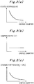
- Fig. 2 includes graphs showing relations of an orifice diameter with a static stiffness, a damping ratio, and a dynamic stiffness, respectively, in a conventional rolling mill.
- Fig. 3 includes graphs showing relations of the orifice diameter with the static stiffness, the damping ratio, and the dynamic stiffness, respectively, in the rolling mill according to the first embodiment of the present invention.
- Figs. 2 (a) and 3 (a) are each a graph showing the relation between the static stiffness and the orifice diameter.
- Figs. 2(b) and 3(b) are each a graph showing the relation between the damping ratio and the orifice diameter.
- Figs. 2(c) and 3(c) are each a graph showing the relation between the dynamic stiffness and the orifice diameter.
- this embodiment provides the chamber 21, and finds an appropriate range of the orifice diameter, which can further increase a vibration control effect, by focusing on the orifice diameter and the damping ratio, i.e., the dynamic stiffness.
- a valve stand is located distant from the hydraulic cylinder 17 and the diameter of the hydraulic supply-discharge pipe 19 is reduced by using the orifice 20 as well. Accordingly, the mere provision of the orifice 20 can result in a situation where the oil inside the hydraulic supply-discharge pipe 19 flows less smoothly whereby the damping ratio is kept from increasing.
- the chamber is installed in the middle of the hydraulic supply-discharge pipe 19 and on an outlet side of orifice 20, so that the damping ratio can be improved by creating a pressure difference while feeding the oil through the orifice 20.
- the dynamic stiffness was improved in particular by setting a volume of the chamber 21 within predetermined range (to be described later).
- Fig. 4 is a simulation model diagram in terms of the dynamic stiffness.
- Fig. 4 depicts models by using A as the orifice 20, B as the hydraulic supply-discharge pipe 19, K1 as a housing spring constant, K as the static stiffness of the model as a whole, c as a damping coefficient of a structure, D as the housing 11, E as the work rolls 12 and the work roll chocks 13, F as the hydraulic cylinder 17, and P as the hydraulic pump, respectively.
- motion equations of the work rolls 12 and the work roll chocks 13, and a characteristic of the orifice 20 to determine its flow rate depending on the pressure difference are incorporated.
- the dynamic stiffness K d is defined as the smallest value out of the ratios of the excitation force f 0 to the work roll displacement X, which are obtained by giving values of the excitation force f 0 to the respective excitation frequency ⁇ .
- the dynamic stiffness K d is a value to determine movement at the time of vibration.
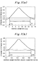
- Fig. 7(a) is a graph showing a relation between the orifice diameter and the dynamic stiffness ratio
- Fig. 7(b) is a graph showing a relation between the dynamic stiffness ratio and a ratio of the orifice diameter to an inside diameter of the hydraulic supply-discharge pipe 19 (an orifice diameter-to-pipe-inside-diameter ratio).
- Fig. 7(a) shows the case where the inside diameter (the pipe inside diameter) of the hydraulic supply-discharge pipe 19 is equal to ⁇ 18 mm.
- the dynamic stiffness ratio means a ratio to the dynamic stiffness when the orifice diameter is equal to 0, i.e., when the hydraulic cylinder is fully closed (the same applies to Figs. 8 and 9 ).
- Figs. 7(a) and 7(b) the orifice diameter previously designed to be equal to or below about ⁇ 2.0 mm is then designed in a larger size to the contrary. In this way, it turned out that the dynamic stiffness ratio was improved further. Particularly, in Fig. 7(a) , there are inflection points where the orifice diameter is equal to 2.5 mm and 15 mm, respectively, and the dynamic stiffness ratio rises sharply in the range from 2.5 mm to 15 mm inclusive. In Fig.
- the orifice diameter is set to such a size equal to or above ⁇ 2.5 mm with the ratio to the pipe inside diameter within the range of 15% to 85%.
- the dynamic stiffness ratio is improved to 1.2 or above.
- Fig. 8 (a) is a graph showing a relation between the volume of the chamber 21 (a chamber volume) and the dynamic stiffness ratio
- Fig. 8(b) is a graph showing a relation between the dynamic stiffness ratio and a ratio of the chamber volume to a volume of the hydraulic cylinder 17 (a chamber-volume-to-cylinder-volume ratio).
- the cylinder volume is defined as a volume to be determined by a cylinder diameter and a stroke.
- the cylinder sizes is described as D 250 mm (a head diameter) / d 230 mm (a rod diameter) ⁇ a 90-mm stroke
- the chamber-volume-to-cylinder-volume ratio is in a range from 0.07 to 1.8 in the case of the chamber volume in a range from 0.3 to 8.0 liters as described later.
- the dynamic stiffness ratio is improved to 1.2 and above, or up to about 3.0 at the maximum.
- the dynamic stiffness ratio is improved to 1.2 and above, or up to about 3.0 at the maximum.
- the chamber-volume-to-cylinder-volume ratio is set equal to or above 0.07 and equal to or below 1.8 (i.e., equal to or above 7% and equal to or below 180%).
- the dynamic stiffness ratio is equal to or above 1.2 in this case.
- the cylinder-to-orifice distance is set equal or below 7.0 m.
- the orifice-to-chamber distance is set equal or below 3.5 m.
- the rolling mill according to the first embodiment of the present invention has been described above.
- the rolling mill according to the first embodiment of the present invention is provided with the orifice 20 and the chamber 21 only on the head side of the hydraulic supply-discharge pipe 19.
- another orifice and another chamber may be provided on a rod side thereof.
- only the orifice may be provided while not providing the chamber. In any case, the effect of the orifice 20 and the chamber 21 remains the same.
- the rolling mill according to the first embodiment of the present invention can control mill vibration without having to reduce the orifice diameter excessively.
- the present invention is suitable for a rolling mill, or more specifically, to a device to control vibration of a hot rolling mill which occurs in the course of rolling with the rolling mill.
Landscapes
- Engineering & Computer Science (AREA)
- Mechanical Engineering (AREA)
- Control Of Metal Rolling (AREA)
- Reduction Rolling/Reduction Stand/Operation Of Reduction Machine (AREA)
Description
- The present invention relates to a rolling mill, or more specifically, to a device to control vibration of a hot rolling mill which occurs in the course of rolling with the rolling mill.
- Hot rolling may cause mill vibration in the course of rolling. The mill vibration means vibration of upper and lower work rolls (WRs) in a horizontal direction (a rolling direction) and in mutually reverse phases. Here, the mutually reverse phases represent a phenomenon that the lower WR moves to a downstream side when the upper WR moves to an upstream side, and on the other hand, the lower WR moves to the upstream side when the upper WR moves to the downstream side. The mill vibration leads to a fluctuation in strip thickness, loosening of various fastening bolts used in the rolling mill, vibration of pipes, and the like.
- The vibration has heretofore been controlled by focusing on a static stiffness. Specifically, a conventional concept has been designed to eliminate a gap between a housing and a work roll chock in a rolling mill by applying pressure with a hydraulic cylinder, and thus to improve the static stiffness in a horizontal direction. Further, by way of extension, the static stiffness has been improved by reducing a diameter (an orifice diameter) of an orifice provided to a hydraulic supply-discharge pipe of a hydraulic cylinder (see
Patent Document 1 below). - Patent Document 1: Japanese Patent Application Publication No.
2001-113308 EP 1120172 A1 (The pre-characterising part ofclaim 1 starts out fromFigs. 1 and2 of this document.) - As described above, the conventional technique provides the reduced orifice diameter (about φ2.0 mm or below) as the means for further improving the static stiffness. Nonetheless, the reduction in the orifice diameter has a limitation because too small an orifice diameter may cause dust clogging, a failure to achieve a designed cylinder operation speed, and the like. Hence, there has been a problem that a sufficient vibration control effect was not actually available therefrom.
- In view of the above, an object of the present invention is to provide a rolling mill which is capable of controlling mill vibration without having to reduce an orifice diameter excessively.
- The invention is defined by the appended claims.
- A rolling mill according to a first aspect of the invention to solve the above problems is characterized in that the rolling mill comprises:
- a housing;
- a pair of upper and lower work roll chocks supported by the housing;
- a pair of upper and lower work rolls opposed to each other and pivotally supported by the pair of upper and lower work roll chocks, respectively;
- roll gap controlling means for applying a predetermined pressure to the work rolls;
- a pair of upper and lower first supporting means provided to the housing at positions on one side in a rolling direction for supporting the pair of upper and lower work roll chocks; and
- a pair of upper and lower second supporting means provided to the housing at positions on another side in the rolling direction for supporting the pair of upper and lower work roll chocks, wherein
- the first supporting means is used as hydraulic pressing means and is made capable of pressing the pair of upper and lower work roll chocks in a horizontal direction,
- a flow contracting unit and an expanding unit are provided to a portion of a hydraulic supply-discharge pipe on a head side of the hydraulic pressing means, while disposing the flow contracting unit closer to the hydraulic pressing means than the expanding unit, and
- an inside diameter of the flow contracting unit is set equal to or above φ2.5 mm and in a size of from 15% to 85% relative to an inside diameter of the hydraulic supply-discharge pipe.
- A rolling mill according to a second aspect of the invention to solve the above problems is the rolling mill according to the first aspect of the invention, characterized in that a volume of the expanding unit is set in a range from 7% to 180% relative to a volume of the hydraulic pressing means .
- A rolling mill according to a third aspect of the invention to solve the above problems is the rolling mill according to the first or second aspect of the invention, characterized in that a distance between the flow contracting unit at the hydraulic supply-discharge pipe and the hydraulic pressing means is set equal to or below 7 m.
- A rolling mill according to a fourth aspect of the invention to solve the above problems is the rolling mill according to any one of the first to third aspects of the invention, characterized in that a distance between the expanding unit and the flow contracting unit at the hydraulic supply-discharge pipe is set equal to or below 3.5 m.
- According to a rolling mill of the present invention, it is possible to control mill vibration without having to reduce an orifice diameter excessively.
-
-
Fig. 1 includes schematic diagrams of a rolling mill according to a first embodiment of the present invention. -
Fig. 2 includes graphs showing relations of an orifice diameter with a static stiffness, a damping ratio, and a dynamic stiffness, respectively, in a conventional rolling mill. -
Fig. 3 includes graphs showing relations of an orifice diameter with a static stiffness, a damping ratio, and a dynamic stiffness, respectively, in the rolling mill according to the first embodiment of the present invention. -
Fig. 4 is an analysis model diagram concerning the dynamic stiffness of the rolling mill according to the first embodiment of the present invention. -
Fig. 5 is a graph showing an excitation force and a work roll displacement in the rolling mill according to the first embodiment of the present invention. -
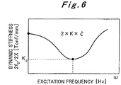
Fig. 6 is a graph showing a relation between an excitation frequency and the dynamic stiffness in the rolling mill according to the first embodiment of the present invention. -
Fig. 7 illustrates graphs showing a relation between the orifice diameter and a dynamic stiffness ratio in the rolling mill according to the first embodiment of the present invention. -
Fig. 8 illustrates graphs showing a relation between a chamber volume and the dynamic stiffness ratio in the rolling mill according to the first embodiment of the present invention. -
Fig. 9 is a graph showing a relation between a cylinder-to-orifice distance and the dynamic stiffness ratio in the rolling mill according to the first embodiment of the present invention. -
Fig. 10 is a graph showing a relation between an orifice-to-chamber distance and the dynamic stiffness ratio in the rolling mill according to the first embodiment of the present invention. - In regard to a rolling mill according to the present invention, the earnest investigations by the inventors have revealed a characteristic that a damping ratio varies with an orifice diameter by providing an appropriate chamber, and also the existence of an appropriate range for the orifice diameter from the viewpoint of controlling mill vibration by focusing on a dynamic stiffness derived from a static stiffness and the damping ratio. In addition, the existence of an appropriate range for a chamber volume has also been revealed. A rolling mill according to the present invention will be described below in the form of an embodiment and by using the drawings.
- First, a rolling mill according to a first embodiment of the present invention will be described by using
Fig. 1. Fig. 1 includes schematic diagrams of the rolling mill according to the first embodiment of the present invention. - As shown in
Fig. 1(a) , the rolling mill according to the first embodiment of the present invention includes ahousing 11,work rolls 12,work roll chocks 13,backup rolls 14,backup roll chocks 15, roll gap controllingmeans 16, hydraulic cylinders 17 (hydraulic pressing means, first supporting means), housing liners 18 (second supporting means), a hydraulic supply-discharge pipe 19, an orifice 20 (a flow contracting unit), a chamber 21 (an expanding unit), and ahydraulic pressure source 22. - The pair of upper and lower
work roll chocks 13 are supported by thehousing 11. - The pair of upper and
lower work rolls 12 are opposed to each other and are pivotally supported by the pair of upper and lowerwork roll chocks 13, respectively. - The pair of upper and
lower backup rolls 14 are pivotally supported by the pair of upper andbackup roll chocks 15 and are opposed to the pair of upper andlower work rolls 12, respectively. - The roll gap controlling means 16 applies a predetermined pressure to the work rolls 12 through the
backup rolls 14. - The pair of upper and lower
hydraulic cylinders 17 are provided to thehousing 11 at positions on one side in a rolling direction so as to support the pair of upper and lowerwork roll chocks 13, and are made capable of pressing the pair of upper and lowerwork roll chocks 13 in a horizontal direction. - The pair of upper and
lower housing liners 18 are provided to thehousing 11 at positions on the other side in the rolling direction so as to support the pair of upper and lowerwork roll chocks 13. - The
orifice 20 and thechamber 21 are provided to a portion of the hydraulic supply-discharge pipe 19 on a head side of the correspondinghydraulic cylinder 17 such that theorifice 20 is disposed closer to thehydraulic cylinder 17 than thechamber 21 is. Alternatively, as shown inFig. 1(b) , the rolling mill according to the first embodiment of the present invention may be configured to dispose thechamber 21 while branching off a pipe from the hydraulic supply-discharge pipe 19. - In the following, a description will be given of an orifice diameter (an inside diameter of the orifice 20).
- The rolling mill according to the first embodiment of the present invention focuses on an improvement of a dynamic stiffness in the horizontal direction of the rolling mill in order to control mill vibration. The dynamic stiffness (Kd) is expressed by 2 × a static stiffness (K) × a damping ratio (ζ).
-
Fig. 2 includes graphs showing relations of an orifice diameter with a static stiffness, a damping ratio, and a dynamic stiffness, respectively, in a conventional rolling mill.Fig. 3 includes graphs showing relations of the orifice diameter with the static stiffness, the damping ratio, and the dynamic stiffness, respectively, in the rolling mill according to the first embodiment of the present invention.Figs. 2 (a) and3 (a) are each a graph showing the relation between the static stiffness and the orifice diameter.Figs. 2(b) and3(b) are each a graph showing the relation between the damping ratio and the orifice diameter.Figs. 2(c) and3(c) are each a graph showing the relation between the dynamic stiffness and the orifice diameter. - As shown in
Figs. 2 (a) and 2(b) , the static stiffness and the dynamic stiffness have heretofore been considered to become larger as the orifice diameter is made smaller based on the concept that the damping ratio remains constant irrespective of the orifice diameter. However, the earnest investigations by the inventors have revealed the characteristic that the damping ratio varies with the orifice diameter as shown inFig. 3(b) by providing an appropriate chamber. - Specifically, as shown in
Figs. 3(a) and 3(b) , while the static stiffness becomes larger as the orifice diameter is made smaller, the damping ratio is reduced because oil in the hydraulic supply-discharge pipe 19 flows less smoothly in theorifice 20. On the other hand, while the static stiffness becomes smaller as the orifice diameter is made larger, the damping ratio is increased because the oil in the hydraulic supply-discharge pipe 19 flows more smoothly in theorifice 20. - Further, as shown in
Fig. 3(c) , it turned out that the dynamic stiffness was improved in particular by setting the orifice diameter within a predetermined range (to be described later). - In the past, nonetheless, in the case where only an
orifice 20 was provided to the hydraulic supply-discharge pipe 19, the orifice diameter has been reduced (to about φ 2.0 mm or below) while focusing only on the static stiffness based on the concept as shown inFigs. 2(a) and 2(b) that the damping ratio remains constant even if the orifice diameter is expanded. - However, it turned out that the installation of the
chamber 21 made it possible to improve the damping ratio along with the expansion of the orifice diameter as mentioned above. Accordingly, this embodiment provides thechamber 21, and finds an appropriate range of the orifice diameter, which can further increase a vibration control effect, by focusing on the orifice diameter and the damping ratio, i.e., the dynamic stiffness. - In the meantime, a valve stand is located distant from the
hydraulic cylinder 17 and the diameter of the hydraulic supply-discharge pipe 19 is reduced by using theorifice 20 as well. Accordingly, the mere provision of theorifice 20 can result in a situation where the oil inside the hydraulic supply-discharge pipe 19 flows less smoothly whereby the damping ratio is kept from increasing. - On the other hand, according to the rolling mill of the first embodiment of the present invention, the chamber is installed in the middle of the hydraulic supply-
discharge pipe 19 and on an outlet side oforifice 20, so that the damping ratio can be improved by creating a pressure difference while feeding the oil through theorifice 20. - Meanwhile, from the viewpoint of the dynamic stiffness, it also turned out that the dynamic stiffness was improved in particular by setting a volume of the
chamber 21 within predetermined range (to be described later). - Now, the range of the orifice diameter with which to improve the dynamic stiffness in particular will be determined.
-
Fig. 4 is a simulation model diagram in terms of the dynamic stiffness.Fig. 4 depicts models by using A as theorifice 20, B as the hydraulic supply-discharge pipe 19, K1 as a housing spring constant, K as the static stiffness of the model as a whole, c as a damping coefficient of a structure, D as thehousing 11, E as the work rolls 12 and the work roll chocks 13, F as thehydraulic cylinder 17, and P as the hydraulic pump, respectively. Here, motion equations of the work rolls 12 and the work roll chocks 13, and a characteristic of theorifice 20 to determine its flow rate depending on the pressure difference are incorporated. - According to
Fig. 4 , the motion equations are expressed by the following formulae (1) and (2):
[Formula 1]
[Formula 2]
- In addition, the dynamic stiffness Kd is expressed by the following formula (3):
[Formula 3]
- From the formula (1), a relation between the excitation force f0 and the work roll displacement X is derived as shown in a graph of
Fig. 5 . - Then, the work roll displacement X for each excitation frequency ω is calculated and a ratio of the excitation force f0 to the work roll displacement X is calculated (the formula (3)). Note that values of this ratio vary with values of the excitation frequency ω as shown in
Fig. 6 . - Therefore, the smallest value out of the ratios of the excitation force f0 to the work roll displacement X that vary with the values of the excitation frequency ω is evaluated as the dynamic stiffness Kd. Specifically, the dynamic stiffness Kd is defined as the smallest value out of the ratios of the excitation force f0 to the work roll displacement X, which are obtained by giving values of the excitation force f0 to the respective excitation frequency ω. The dynamic stiffness Kd is a value to determine movement at the time of vibration.
- The values of the dynamic stiffness Kd are evaluated as described above by using various orifice diameters. Results are shown in
Figs. 7(a) and 7(b) . -
Fig. 7(a) is a graph showing a relation between the orifice diameter and the dynamic stiffness ratio, andFig. 7(b) is a graph showing a relation between the dynamic stiffness ratio and a ratio of the orifice diameter to an inside diameter of the hydraulic supply-discharge pipe 19 (an orifice diameter-to-pipe-inside-diameter ratio). Here,Fig. 7(a) shows the case where the inside diameter (the pipe inside diameter) of the hydraulic supply-discharge pipe 19 is equal to φ18 mm. In the meantime, the dynamic stiffness ratio means a ratio to the dynamic stiffness when the orifice diameter is equal to 0, i.e., when the hydraulic cylinder is fully closed (the same applies toFigs. 8 and9 ). - As shown in
Figs. 7(a) and 7(b) , the orifice diameter previously designed to be equal to or below about φ2.0 mm is then designed in a larger size to the contrary. In this way, it turned out that the dynamic stiffness ratio was improved further. Particularly, inFig. 7(a) , there are inflection points where the orifice diameter is equal to 2.5 mm and 15 mm, respectively, and the dynamic stiffness ratio rises sharply in the range from 2.5 mm to 15 mm inclusive. InFig. 7(b) , there are inflection points where the orifice diameter-to-pipe-inside-diameter ratio is equal to 0.15 (15%) and 0.85 (85%), respectively, and the dynamic stiffness ratio rises sharply in the range from 15% to 85% inclusive. - In addition, the previously problematic dust clogging is less likely to occur by setting the orifice diameter equal to or above φ2.5 mm.
- Accordingly, in the rolling mill of the first embodiment of the present invention, the orifice diameter is set to such a size equal to or above φ2.5 mm with the ratio to the pipe inside diameter within the range of 15% to 85%. In this case, the dynamic stiffness ratio is improved to 1.2 or above.
- Meanwhile, a relation between a volume of the
chamber 21 and the dynamic stiffness ratio has also been sought. Results turned out as shown inFigs. 8(a) and 8(b) . -
Fig. 8 (a) is a graph showing a relation between the volume of the chamber 21 (a chamber volume) and the dynamic stiffness ratio, andFig. 8(b) is a graph showing a relation between the dynamic stiffness ratio and a ratio of the chamber volume to a volume of the hydraulic cylinder 17 (a chamber-volume-to-cylinder-volume ratio). - Here, the cylinder volume is defined as a volume to be determined by a cylinder diameter and a stroke. In a specific example, when the cylinder sizes is described as D 250 mm (a head diameter) / d 230 mm (a rod diameter) × a 90-mm stroke, the cylinder volume Vc is expressed by Vc = (π/4) × 252 × 9 (cm3), which is equal to about 4.4 liters. Accordingly, the chamber-volume-to-cylinder-volume ratio is in a range from 0.07 to 1.8 in the case of the chamber volume in a range from 0.3 to 8.0 liters as described later.
- As shown in
Fig. 8(a) , when the chamber volume is equal to or above 0.3 liter, the dynamic stiffness ratio is improved to 1.2 and above, or up to about 3.0 at the maximum. In other words, as shown inFig. 8(b) , when the chamber-volume-to-cylinder-volume ratio is equal to or above 0.07, the dynamic stiffness ratio is improved to 1.2 and above, or up to about 3.0 at the maximum. - Here, regarding values of the chamber volume greater than 8.0 liters in
Fig. 8(a) , i.e., values of the chamber-volume-to-cylinder-volume ratio greater than 1.8 inFig. 8(b) , the graphs reach saturation levels where the dynamic stiffness ratio is hardly improved any more. Thus, the increase in chamber volume above the aforementioned value turned out not to contribute to a significant increase in effect. - Accordingly, in the rolling mill of the first embodiment of the present invention, the chamber-volume-to-cylinder-volume ratio is set equal to or above 0.07 and equal to or below 1.8 (i.e., equal to or above 7% and equal to or below 180%). Here, the dynamic stiffness ratio is equal to or above 1.2 in this case.
- In the meantime, a relation between a distance from the
hydraulic cylinder 17 to the orifice 20 (a cylinder-to-orifice distance) and the dynamic stiffness ratio has also been investigated. As a consequence, the dynamic stiffness ratio turns out to be equal to or above 1.2 when the cylinder-to-orifice distance is equal to or below 7.0 mas shown in a graph ofFig. 9 . - Accordingly, in the rolling mill of the first embodiment of the present invention, the cylinder-to-orifice distance is set equal or below 7.0 m.
- In addition, a relation between a distance from the
orifice 20 to the chamber 21 (an orifice-to-chamber distance) and the dynamic stiffness ratio has also been investigated. As a consequence, the dynamic stiffness ratio turns out to be equal to or above 1.2 when the orifice-to-chamber distance is equal to or below 3.5 m as shown in a graph ofFig. 10 . - Accordingly, in the rolling mill of the first embodiment of the present invention, the orifice-to-chamber distance is set equal or below 3.5 m.
- The rolling mill according to the first embodiment of the present invention has been described above. In
Figs. 1 and2 , the rolling mill according to the first embodiment of the present invention is provided with theorifice 20 and thechamber 21 only on the head side of the hydraulic supply-discharge pipe 19. In addition, however, another orifice and another chamber may be provided on a rod side thereof. Alternatively, on the rod side of the hydraulic supply-discharge tube 19, only the orifice may be provided while not providing the chamber. In any case, the effect of theorifice 20 and thechamber 21 remains the same. - By adopting the above-described configuration, the rolling mill according to the first embodiment of the present invention can control mill vibration without having to reduce the orifice diameter excessively.
- The present invention is suitable for a rolling mill, or more specifically, to a device to control vibration of a hot rolling mill which occurs in the course of rolling with the rolling mill.
-
- 11
- housing
- 12
- work roll
- 13
- work roll chock
- 14
- backup roll
- 15
- backup roll chock
- 16
- roll gap controlling means
- 17
- hydraulic cylinder
- 18
- housing liner
- 19
- hydraulic supply-discharge pipe
- 20
- orifice
- 21
- chamber
- 22
- hydraulic pressure source
Claims (4)
- A rolling mill which comprises:a housing (11);a pair of upper and lower work roll chocks (13) supported by the housing (11);a pair of upper and lower work rolls (12) opposed to each other and pivotally supported by the pair of upper and lower work roll chocks (13), respectively;roll gap controlling means (16) for applying a predetermined pressure to the work rolls (12);a pair of upper and lower first supporting means (17) provided to the housing (11) at positions on one side in a rolling direction for supporting the pair of upper and lower work roll chocks (13); anda pair of upper and lower second supporting means (18) provided to the housing (11) at positions on another side in the rolling direction for supporting the pair of upper and lower work roll chocks (13), whereinthe first supporting means (17) is used as hydraulic pressing means (17) and is made capable of pressing the pair of upper and lower work roll chocks (13) in a horizontal direction, anda flow contracting unit (20) is provided to a portion of a hydraulic supply-discharge pipe (19) on a head side of the hydraulic pressing means (17),characterised in thatan expanding unit (21) is provided to the portion of said hydraulic supply-discharge pipe (19) on the head side of the hydraulic pressing means (17), while disposing the flow contracting unit (20) closer to the hydraulic pressing means (17) than the expanding unit (21), andan inside diameter of the flow contracting unit (20) is set equal to or above φ2.5 mm and in a size of from 15% to 85% relative to an inside diameter of the hydraulic supply-discharge pipe (19).
- The rolling mill according to claim 1, characterized in that a volume of the expanding unit (21) is set in a range from 7% to 180% relative to a volume of the hydraulic pressing means (17) .
- The rolling mill according to claim 1 or 2, characterized in that a distance between the flow contracting unit (20) at the hydraulic supply-discharge pipe (19) and the hydraulic pressing means (17) is set equal to or below 7 m.
- The rolling mill according to any one of claims 1 to 3, characterized in that a distance between the expanding unit (21) and the flow contracting unit (20) at the hydraulic supply-discharge pipe (19) is set equal to or below 3.5 m.
Applications Claiming Priority (1)
| Application Number | Priority Date | Filing Date | Title |
|---|---|---|---|
| PCT/JP2014/077052 WO2016056097A1 (en) | 2014-10-09 | 2014-10-09 | Rolling mill |
Publications (3)
| Publication Number | Publication Date |
|---|---|
| EP3205417A1 EP3205417A1 (en) | 2017-08-16 |
| EP3205417A4 EP3205417A4 (en) | 2018-06-27 |
| EP3205417B1 true EP3205417B1 (en) | 2019-09-04 |
Family
ID=55652753
Family Applications (1)
| Application Number | Title | Priority Date | Filing Date |
|---|---|---|---|
| EP14903624.6A Active EP3205417B1 (en) | 2014-10-09 | 2014-10-09 | Rolling mill |
Country Status (5)
| Country | Link |
|---|---|
| EP (1) | EP3205417B1 (en) |
| JP (1) | JP6345262B2 (en) |
| KR (1) | KR101908872B1 (en) |
| CN (1) | CN107000002B (en) |
| WO (1) | WO2016056097A1 (en) |
Family Cites Families (9)
| Publication number | Priority date | Publication date | Assignee | Title |
|---|---|---|---|---|
| CN85101137B (en) * | 1985-04-01 | 1988-01-06 | 株式会社日立制作所 | Rolling mill |
| JPS61259810A (en) * | 1985-05-10 | 1986-11-18 | Ishikawajima Harima Heavy Ind Co Ltd | Method and apparatus for rolling |
| JPH02151310A (en) * | 1988-12-05 | 1990-06-11 | Sumitomo Light Metal Ind Ltd | Vibration isolator in rolling mill |
| JPH04190904A (en) * | 1990-11-22 | 1992-07-09 | Ube Ind Ltd | rolling mill |
| JP4402264B2 (en) * | 1999-08-11 | 2010-01-20 | 三菱重工業株式会社 | Rolling mill |
| JP2004314089A (en) * | 2003-04-11 | 2004-11-11 | Ishikawajima Harima Heavy Ind Co Ltd | Roll gap adjusting device and adjusting method, rolling mill and rolling method |
| FR2869819B1 (en) * | 2004-05-07 | 2006-08-04 | Vai Clecim Soc Par Actions Sim | METHOD AND DEVICE FOR DAMPING A ROLLER CAGE |
| JP4679642B2 (en) * | 2006-06-30 | 2011-04-27 | 三菱日立製鉄機械株式会社 | Rolling mill |
| CN202539185U (en) * | 2011-11-23 | 2012-11-21 | 西安曼海特工业技术有限公司 | A shake-proof sheet steel rolling mill |
-
2014
- 2014-10-09 KR KR1020177004801A patent/KR101908872B1/en active Active
- 2014-10-09 CN CN201480082485.1A patent/CN107000002B/en active Active
- 2014-10-09 JP JP2016552761A patent/JP6345262B2/en active Active
- 2014-10-09 WO PCT/JP2014/077052 patent/WO2016056097A1/en not_active Ceased
- 2014-10-09 EP EP14903624.6A patent/EP3205417B1/en active Active
Non-Patent Citations (1)
| Title |
|---|
| None * |
Also Published As
| Publication number | Publication date |
|---|---|
| KR101908872B1 (en) | 2018-10-16 |
| EP3205417A1 (en) | 2017-08-16 |
| EP3205417A4 (en) | 2018-06-27 |
| JPWO2016056097A1 (en) | 2017-04-27 |
| WO2016056097A1 (en) | 2016-04-14 |
| JP6345262B2 (en) | 2018-06-20 |
| CN107000002B (en) | 2019-08-27 |
| KR20170033408A (en) | 2017-03-24 |
| CN107000002A (en) | 2017-08-01 |
Similar Documents
| Publication | Publication Date | Title |
|---|---|---|
| He et al. | Research on vertical vibration characteristics of rolling mill based on magnetorheological fluid damper absorber | |
| Yun et al. | Chatter in the strip rolling process, part 1: dynamic model of rolling | |
| US6510721B1 (en) | Rolling mill | |
| CN101842760B (en) | Control device with linear unit for position control of hydraulic cylinder units | |
| Radionov et al. | Automatic gap control of plan view pattern control mechatronics system | |
| Pagilla et al. | Dynamics and control of accumulators in continuous strip processing lines | |
| EP3205417A1 (en) | Rolling mill | |
| Guo et al. | The flow model of the overlap spool valve considering the transition between laminar and turbulent flow | |
| Genić et al. | Economic optimization of pipe diameter for complete turbulence | |
| Al-Abri et al. | Analytical model for stick–slip phenomenon in solid tubular expansion | |
| CN209701941U (en) | Tension control device for slitting tension machine | |
| Wu et al. | Coupling vibration model for hot rolling mills and its application | |
| TW200512051A (en) | Rolling device | |
| JP2014034039A (en) | Method and apparatus for controlling motion of tandem mill, and method and apparatus for producing hot-rolled steel sheet | |
| Kim et al. | Short stroke control model for improving width precision at head and tail of slab in hot vertical–horizontal rolling process | |
| CN203778500U (en) | Constant-pressure turbid circulating water system | |
| JP4679642B2 (en) | Rolling mill | |
| CA2594794C (en) | Method and computer program for controlling a rolling process | |
| Bosserman II et al. | Fundamentals of Hydraulic Transients | |
| Dvořák et al. | Pressure regulators as valves for saving compressed air and their influence on system dynamics | |
| Murti | Effect of velocity slip in an externally pressurized porous thrust bearing working with an incompressible fluid | |
| JP2014161894A (en) | Manufacturing apparatus and manufacturing method for differential thickness steel plate | |
| Rekach et al. | Water Hammer Decrease by Introduction of Pipes With Low Speed Pressure Waves Propagation | |
| Lozinsky et al. | RESEARCH OF THE CONTOL SYSTEM OF THE PROPORTIONAL ELECTROHYDRAULIC DISTRIBUTOR | |
| Kővári | Dynamic Model of Rolling Mill’s Electro-Hydraulic Gap Adjustment System |
Legal Events
| Date | Code | Title | Description |
|---|---|---|---|
| STAA | Information on the status of an ep patent application or granted ep patent |
Free format text: STATUS: THE INTERNATIONAL PUBLICATION HAS BEEN MADE |
|
| PUAI | Public reference made under article 153(3) epc to a published international application that has entered the european phase |
Free format text: ORIGINAL CODE: 0009012 |
|
| STAA | Information on the status of an ep patent application or granted ep patent |
Free format text: STATUS: REQUEST FOR EXAMINATION WAS MADE |
|
| 17P | Request for examination filed |
Effective date: 20170509 |
|
| AK | Designated contracting states |
Kind code of ref document: A1 Designated state(s): AL AT BE BG CH CY CZ DE DK EE ES FI FR GB GR HR HU IE IS IT LI LT LU LV MC MK MT NL NO PL PT RO RS SE SI SK SM TR |
|
| AX | Request for extension of the european patent |
Extension state: BA ME |
|
| DAX | Request for extension of the european patent (deleted) | ||
| A4 | Supplementary search report drawn up and despatched |
Effective date: 20180528 |
|
| RIC1 | Information provided on ipc code assigned before grant |
Ipc: B21B 31/02 20060101AFI20180522BHEP Ipc: B21B 31/18 20060101ALI20180522BHEP Ipc: B21B 37/00 20060101ALI20180522BHEP Ipc: B21B 13/02 20060101ALI20180522BHEP |
|
| GRAP | Despatch of communication of intention to grant a patent |
Free format text: ORIGINAL CODE: EPIDOSNIGR1 |
|
| STAA | Information on the status of an ep patent application or granted ep patent |
Free format text: STATUS: GRANT OF PATENT IS INTENDED |
|
| RIC1 | Information provided on ipc code assigned before grant |
Ipc: B21B 13/02 20060101ALI20190408BHEP Ipc: B21B 31/02 20060101AFI20190408BHEP Ipc: B21B 31/18 20060101ALI20190408BHEP Ipc: B21B 37/00 20060101ALI20190408BHEP |
|
| INTG | Intention to grant announced |
Effective date: 20190513 |
|
| GRAS | Grant fee paid |
Free format text: ORIGINAL CODE: EPIDOSNIGR3 |
|
| GRAA | (expected) grant |
Free format text: ORIGINAL CODE: 0009210 |
|
| STAA | Information on the status of an ep patent application or granted ep patent |
Free format text: STATUS: THE PATENT HAS BEEN GRANTED |
|
| RAP1 | Party data changed (applicant data changed or rights of an application transferred) |
Owner name: PRIMETALS TECHNOLOGIES JAPAN, LTD. |
|
| AK | Designated contracting states |
Kind code of ref document: B1 Designated state(s): AL AT BE BG CH CY CZ DE DK EE ES FI FR GB GR HR HU IE IS IT LI LT LU LV MC MK MT NL NO PL PT RO RS SE SI SK SM TR |
|
| REG | Reference to a national code |
Ref country code: GB Ref legal event code: FG4D |
|
| REG | Reference to a national code |
Ref country code: CH Ref legal event code: EP |
|
| REG | Reference to a national code |
Ref country code: AT Ref legal event code: REF Ref document number: 1174633 Country of ref document: AT Kind code of ref document: T Effective date: 20190915 |
|
| REG | Reference to a national code |
Ref country code: DE Ref legal event code: R096 Ref document number: 602014053254 Country of ref document: DE |
|
| REG | Reference to a national code |
Ref country code: IE Ref legal event code: FG4D |
|
| REG | Reference to a national code |
Ref country code: NL Ref legal event code: MP Effective date: 20190904 |
|
| REG | Reference to a national code |
Ref country code: LT Ref legal event code: MG4D |
|
| PG25 | Lapsed in a contracting state [announced via postgrant information from national office to epo] |
Ref country code: SE Free format text: LAPSE BECAUSE OF FAILURE TO SUBMIT A TRANSLATION OF THE DESCRIPTION OR TO PAY THE FEE WITHIN THE PRESCRIBED TIME-LIMIT Effective date: 20190904 Ref country code: BG Free format text: LAPSE BECAUSE OF FAILURE TO SUBMIT A TRANSLATION OF THE DESCRIPTION OR TO PAY THE FEE WITHIN THE PRESCRIBED TIME-LIMIT Effective date: 20191204 Ref country code: NO Free format text: LAPSE BECAUSE OF FAILURE TO SUBMIT A TRANSLATION OF THE DESCRIPTION OR TO PAY THE FEE WITHIN THE PRESCRIBED TIME-LIMIT Effective date: 20191204 Ref country code: HR Free format text: LAPSE BECAUSE OF FAILURE TO SUBMIT A TRANSLATION OF THE DESCRIPTION OR TO PAY THE FEE WITHIN THE PRESCRIBED TIME-LIMIT Effective date: 20190904 Ref country code: LT Free format text: LAPSE BECAUSE OF FAILURE TO SUBMIT A TRANSLATION OF THE DESCRIPTION OR TO PAY THE FEE WITHIN THE PRESCRIBED TIME-LIMIT Effective date: 20190904 Ref country code: FI Free format text: LAPSE BECAUSE OF FAILURE TO SUBMIT A TRANSLATION OF THE DESCRIPTION OR TO PAY THE FEE WITHIN THE PRESCRIBED TIME-LIMIT Effective date: 20190904 |
|
| PG25 | Lapsed in a contracting state [announced via postgrant information from national office to epo] |
Ref country code: GR Free format text: LAPSE BECAUSE OF FAILURE TO SUBMIT A TRANSLATION OF THE DESCRIPTION OR TO PAY THE FEE WITHIN THE PRESCRIBED TIME-LIMIT Effective date: 20191205 Ref country code: LV Free format text: LAPSE BECAUSE OF FAILURE TO SUBMIT A TRANSLATION OF THE DESCRIPTION OR TO PAY THE FEE WITHIN THE PRESCRIBED TIME-LIMIT Effective date: 20190904 Ref country code: RS Free format text: LAPSE BECAUSE OF FAILURE TO SUBMIT A TRANSLATION OF THE DESCRIPTION OR TO PAY THE FEE WITHIN THE PRESCRIBED TIME-LIMIT Effective date: 20190904 Ref country code: ES Free format text: LAPSE BECAUSE OF FAILURE TO SUBMIT A TRANSLATION OF THE DESCRIPTION OR TO PAY THE FEE WITHIN THE PRESCRIBED TIME-LIMIT Effective date: 20190904 Ref country code: AL Free format text: LAPSE BECAUSE OF FAILURE TO SUBMIT A TRANSLATION OF THE DESCRIPTION OR TO PAY THE FEE WITHIN THE PRESCRIBED TIME-LIMIT Effective date: 20190904 |
|
| PG25 | Lapsed in a contracting state [announced via postgrant information from national office to epo] |
Ref country code: EE Free format text: LAPSE BECAUSE OF FAILURE TO SUBMIT A TRANSLATION OF THE DESCRIPTION OR TO PAY THE FEE WITHIN THE PRESCRIBED TIME-LIMIT Effective date: 20190904 Ref country code: RO Free format text: LAPSE BECAUSE OF FAILURE TO SUBMIT A TRANSLATION OF THE DESCRIPTION OR TO PAY THE FEE WITHIN THE PRESCRIBED TIME-LIMIT Effective date: 20190904 Ref country code: NL Free format text: LAPSE BECAUSE OF FAILURE TO SUBMIT A TRANSLATION OF THE DESCRIPTION OR TO PAY THE FEE WITHIN THE PRESCRIBED TIME-LIMIT Effective date: 20190904 Ref country code: PT Free format text: LAPSE BECAUSE OF FAILURE TO SUBMIT A TRANSLATION OF THE DESCRIPTION OR TO PAY THE FEE WITHIN THE PRESCRIBED TIME-LIMIT Effective date: 20200106 Ref country code: PL Free format text: LAPSE BECAUSE OF FAILURE TO SUBMIT A TRANSLATION OF THE DESCRIPTION OR TO PAY THE FEE WITHIN THE PRESCRIBED TIME-LIMIT Effective date: 20190904 |
|
| PG25 | Lapsed in a contracting state [announced via postgrant information from national office to epo] |
Ref country code: IS Free format text: LAPSE BECAUSE OF FAILURE TO SUBMIT A TRANSLATION OF THE DESCRIPTION OR TO PAY THE FEE WITHIN THE PRESCRIBED TIME-LIMIT Effective date: 20200224 Ref country code: SK Free format text: LAPSE BECAUSE OF FAILURE TO SUBMIT A TRANSLATION OF THE DESCRIPTION OR TO PAY THE FEE WITHIN THE PRESCRIBED TIME-LIMIT Effective date: 20190904 Ref country code: CZ Free format text: LAPSE BECAUSE OF FAILURE TO SUBMIT A TRANSLATION OF THE DESCRIPTION OR TO PAY THE FEE WITHIN THE PRESCRIBED TIME-LIMIT Effective date: 20190904 Ref country code: SM Free format text: LAPSE BECAUSE OF FAILURE TO SUBMIT A TRANSLATION OF THE DESCRIPTION OR TO PAY THE FEE WITHIN THE PRESCRIBED TIME-LIMIT Effective date: 20190904 |
|
| REG | Reference to a national code |
Ref country code: CH Ref legal event code: PL |
|
| REG | Reference to a national code |
Ref country code: DE Ref legal event code: R097 Ref document number: 602014053254 Country of ref document: DE |
|
| PLBE | No opposition filed within time limit |
Free format text: ORIGINAL CODE: 0009261 |
|
| STAA | Information on the status of an ep patent application or granted ep patent |
Free format text: STATUS: NO OPPOSITION FILED WITHIN TIME LIMIT |
|
| PG2D | Information on lapse in contracting state deleted |
Ref country code: IS |
|
| PG25 | Lapsed in a contracting state [announced via postgrant information from national office to epo] |
Ref country code: CH Free format text: LAPSE BECAUSE OF NON-PAYMENT OF DUE FEES Effective date: 20191031 Ref country code: LU Free format text: LAPSE BECAUSE OF NON-PAYMENT OF DUE FEES Effective date: 20191009 Ref country code: LI Free format text: LAPSE BECAUSE OF NON-PAYMENT OF DUE FEES Effective date: 20191031 Ref country code: DK Free format text: LAPSE BECAUSE OF FAILURE TO SUBMIT A TRANSLATION OF THE DESCRIPTION OR TO PAY THE FEE WITHIN THE PRESCRIBED TIME-LIMIT Effective date: 20190904 Ref country code: IS Free format text: LAPSE BECAUSE OF FAILURE TO SUBMIT A TRANSLATION OF THE DESCRIPTION OR TO PAY THE FEE WITHIN THE PRESCRIBED TIME-LIMIT Effective date: 20200105 |
|
| 26N | No opposition filed |
Effective date: 20200605 |
|
| REG | Reference to a national code |
Ref country code: BE Ref legal event code: MM Effective date: 20191031 |
|
| PG25 | Lapsed in a contracting state [announced via postgrant information from national office to epo] |
Ref country code: BE Free format text: LAPSE BECAUSE OF NON-PAYMENT OF DUE FEES Effective date: 20191031 Ref country code: SI Free format text: LAPSE BECAUSE OF FAILURE TO SUBMIT A TRANSLATION OF THE DESCRIPTION OR TO PAY THE FEE WITHIN THE PRESCRIBED TIME-LIMIT Effective date: 20190904 Ref country code: MC Free format text: LAPSE BECAUSE OF FAILURE TO SUBMIT A TRANSLATION OF THE DESCRIPTION OR TO PAY THE FEE WITHIN THE PRESCRIBED TIME-LIMIT Effective date: 20190904 |
|
| GBPC | Gb: european patent ceased through non-payment of renewal fee |
Effective date: 20191204 |
|
| PG25 | Lapsed in a contracting state [announced via postgrant information from national office to epo] |
Ref country code: IE Free format text: LAPSE BECAUSE OF NON-PAYMENT OF DUE FEES Effective date: 20191009 Ref country code: GB Free format text: LAPSE BECAUSE OF NON-PAYMENT OF DUE FEES Effective date: 20191204 Ref country code: FR Free format text: LAPSE BECAUSE OF NON-PAYMENT OF DUE FEES Effective date: 20191104 |
|
| PG25 | Lapsed in a contracting state [announced via postgrant information from national office to epo] |
Ref country code: CY Free format text: LAPSE BECAUSE OF FAILURE TO SUBMIT A TRANSLATION OF THE DESCRIPTION OR TO PAY THE FEE WITHIN THE PRESCRIBED TIME-LIMIT Effective date: 20190904 |
|
| PG25 | Lapsed in a contracting state [announced via postgrant information from national office to epo] |
Ref country code: HU Free format text: LAPSE BECAUSE OF FAILURE TO SUBMIT A TRANSLATION OF THE DESCRIPTION OR TO PAY THE FEE WITHIN THE PRESCRIBED TIME-LIMIT; INVALID AB INITIO Effective date: 20141009 Ref country code: MT Free format text: LAPSE BECAUSE OF FAILURE TO SUBMIT A TRANSLATION OF THE DESCRIPTION OR TO PAY THE FEE WITHIN THE PRESCRIBED TIME-LIMIT Effective date: 20190904 |
|
| REG | Reference to a national code |
Ref country code: AT Ref legal event code: UEP Ref document number: 1174633 Country of ref document: AT Kind code of ref document: T Effective date: 20190904 |
|
| PG25 | Lapsed in a contracting state [announced via postgrant information from national office to epo] |
Ref country code: MK Free format text: LAPSE BECAUSE OF FAILURE TO SUBMIT A TRANSLATION OF THE DESCRIPTION OR TO PAY THE FEE WITHIN THE PRESCRIBED TIME-LIMIT Effective date: 20190904 |
|
| PGFP | Annual fee paid to national office [announced via postgrant information from national office to epo] |
Ref country code: IT Payment date: 20250922 Year of fee payment: 12 |
|
| PGFP | Annual fee paid to national office [announced via postgrant information from national office to epo] |
Ref country code: DE Payment date: 20250902 Year of fee payment: 12 |
|
| PGFP | Annual fee paid to national office [announced via postgrant information from national office to epo] |
Ref country code: AT Payment date: 20250925 Year of fee payment: 12 |
|
| PGFP | Annual fee paid to national office [announced via postgrant information from national office to epo] |
Ref country code: TR Payment date: 20251002 Year of fee payment: 12 |