EP3203522A1 - Oled display substrate, oled display device and mask plate - Google Patents
Oled display substrate, oled display device and mask plate Download PDFInfo
- Publication number
- EP3203522A1 EP3203522A1 EP15791465.6A EP15791465A EP3203522A1 EP 3203522 A1 EP3203522 A1 EP 3203522A1 EP 15791465 A EP15791465 A EP 15791465A EP 3203522 A1 EP3203522 A1 EP 3203522A1
- Authority
- EP
- European Patent Office
- Prior art keywords
- sub
- pixel units
- oled display
- pixel
- pixel unit
- Prior art date
- Legal status (The legal status is an assumption and is not a legal conclusion. Google has not performed a legal analysis and makes no representation as to the accuracy of the status listed.)
- Withdrawn
Links
Images



Classifications
-
- H—ELECTRICITY
- H10—SEMICONDUCTOR DEVICES; ELECTRIC SOLID-STATE DEVICES NOT OTHERWISE PROVIDED FOR
- H10K—ORGANIC ELECTRIC SOLID-STATE DEVICES
- H10K59/00—Integrated devices, or assemblies of multiple devices, comprising at least one organic light-emitting element covered by group H10K50/00
- H10K59/30—Devices specially adapted for multicolour light emission
- H10K59/35—Devices specially adapted for multicolour light emission comprising red-green-blue [RGB] subpixels
- H10K59/352—Devices specially adapted for multicolour light emission comprising red-green-blue [RGB] subpixels the areas of the RGB subpixels being different
-
- H—ELECTRICITY
- H10—SEMICONDUCTOR DEVICES; ELECTRIC SOLID-STATE DEVICES NOT OTHERWISE PROVIDED FOR
- H10K—ORGANIC ELECTRIC SOLID-STATE DEVICES
- H10K59/00—Integrated devices, or assemblies of multiple devices, comprising at least one organic light-emitting element covered by group H10K50/00
- H10K59/10—OLED displays
- H10K59/12—Active-matrix OLED [AMOLED] displays
-
- H—ELECTRICITY
- H10—SEMICONDUCTOR DEVICES; ELECTRIC SOLID-STATE DEVICES NOT OTHERWISE PROVIDED FOR
- H10K—ORGANIC ELECTRIC SOLID-STATE DEVICES
- H10K59/00—Integrated devices, or assemblies of multiple devices, comprising at least one organic light-emitting element covered by group H10K50/00
- H10K59/30—Devices specially adapted for multicolour light emission
- H10K59/35—Devices specially adapted for multicolour light emission comprising red-green-blue [RGB] subpixels
-
- H—ELECTRICITY
- H10—SEMICONDUCTOR DEVICES; ELECTRIC SOLID-STATE DEVICES NOT OTHERWISE PROVIDED FOR
- H10K—ORGANIC ELECTRIC SOLID-STATE DEVICES
- H10K59/00—Integrated devices, or assemblies of multiple devices, comprising at least one organic light-emitting element covered by group H10K50/00
- H10K59/30—Devices specially adapted for multicolour light emission
- H10K59/35—Devices specially adapted for multicolour light emission comprising red-green-blue [RGB] subpixels
- H10K59/353—Devices specially adapted for multicolour light emission comprising red-green-blue [RGB] subpixels characterised by the geometrical arrangement of the RGB subpixels
-
- H—ELECTRICITY
- H10—SEMICONDUCTOR DEVICES; ELECTRIC SOLID-STATE DEVICES NOT OTHERWISE PROVIDED FOR
- H10K—ORGANIC ELECTRIC SOLID-STATE DEVICES
- H10K71/00—Manufacture or treatment specially adapted for the organic devices covered by this subclass
-
- H—ELECTRICITY
- H10—SEMICONDUCTOR DEVICES; ELECTRIC SOLID-STATE DEVICES NOT OTHERWISE PROVIDED FOR
- H10K—ORGANIC ELECTRIC SOLID-STATE DEVICES
- H10K71/00—Manufacture or treatment specially adapted for the organic devices covered by this subclass
- H10K71/10—Deposition of organic active material
- H10K71/16—Deposition of organic active material using physical vapour deposition [PVD], e.g. vacuum deposition or sputtering
- H10K71/164—Deposition of organic active material using physical vapour deposition [PVD], e.g. vacuum deposition or sputtering using vacuum deposition
-
- H—ELECTRICITY
- H10—SEMICONDUCTOR DEVICES; ELECTRIC SOLID-STATE DEVICES NOT OTHERWISE PROVIDED FOR
- H10K—ORGANIC ELECTRIC SOLID-STATE DEVICES
- H10K59/00—Integrated devices, or assemblies of multiple devices, comprising at least one organic light-emitting element covered by group H10K50/00
- H10K59/10—OLED displays
- H10K59/12—Active-matrix OLED [AMOLED] displays
- H10K59/1201—Manufacture or treatment
-
- H—ELECTRICITY
- H10—SEMICONDUCTOR DEVICES; ELECTRIC SOLID-STATE DEVICES NOT OTHERWISE PROVIDED FOR
- H10K—ORGANIC ELECTRIC SOLID-STATE DEVICES
- H10K71/00—Manufacture or treatment specially adapted for the organic devices covered by this subclass
- H10K71/10—Deposition of organic active material
- H10K71/16—Deposition of organic active material using physical vapour deposition [PVD], e.g. vacuum deposition or sputtering
- H10K71/166—Deposition of organic active material using physical vapour deposition [PVD], e.g. vacuum deposition or sputtering using selective deposition, e.g. using a mask
Definitions
- the present invention relates to the field of display technology, and in particular, relates to an OLED display substrate, an OLED display device, and a mask.
- an active matrix organic light emitting diode (AMOLED) display device As compared with a traditional liquid crystal display device, an active matrix organic light emitting diode (AMOLED) display device has advantages of faster response, higher contrast, wider angle of view, and the like.
- AMOLED active matrix organic light emitting diode
- Fig. 1 is a schematic diagram showing the arrangement of sub-pixel units and display regions thereof in an OLED display substrate in the prior art
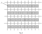
- Fig. 2 is a schematic diagram showing the arrangement of cathodes in the OLED display substrate in the prior art.
- the OLED display substrate includes a plurality of pixel units Pixel, each of which includes a red sub-pixel unit R, a green sub-pixel unit G, and a blue sub-pixel unit B sequentially arranged in the horizontal direction, and all of the sub-pixel units in the OLED display substrate are arranged in a matrix.
- Each of the sub-pixel units includes a display region 1 and a non-display region 2, and the display region 1 of each sub-pixel unit is located at the center of the sub-pixel unit, that is, the display regions 1 of any two adjacent sub-pixel units in the same row are arranged side by side.
- a cathode 3, an anode (not shown), and an electroluminescent layer (not shown) are included in the display region 1, wherein the electroluminescent layer is located between the cathode 3 and the anode, and is used for generating predetermined color light to achieve display.
- the electroluminescent layer may be formed on the OLED display substrate by vapor deposition. During vapor deposition, it is necessary to use a corresponding mask to pattern the electroluminescent layer. During manufacturing the OLED display substrate in the prior art, a vapor deposition process must be performed three times to form electroluminescent layers of respective colors (i.e., red, green, and blue) in the display regions 1 of sub-pixel units of respective colors, respectively.
- respective colors i.e., red, green, and blue
- a distance d1 between the display regions of two adjacent sub-pixel units in the horizontal direction in the OLED display substrate in the prior art is relatively small, and the display regions of two adjacent sub-pixel units in the same row are arranged side by side, which easily causes electroluminescent layer material, which should be located in only one sub-pixel unit, to be evaporated and deposited into the display region of another sub-pixel unit adjacent to the one sub-pixel unit in the same row.
- electroluminescent layer material which should be located in only one sub-pixel unit
- color mixture of the electroluminescent layers with two different colors occurs, which causes the another sub-pixel unit adjacent to the one sub-pixel unit in the same row unable to emit predetermined color light. Therefore, the display of a display device is affected.
- the embodiments of present invention provide an OLED display substrate, an OLED display device, and a mask, which can effectively solve the problem of color mixture of adjacent sub-pixel units in the same row occurring during vapor deposition of an electroluminescent material.
- One embodiment of the present invention provides an OLED display substrate, including a plurality of pixel units, each of which including a plurality of sub-pixel units arranged in horizontal direction, wherein, each of the plurality of sub-pixel units includes a display region and a non-display region, and the display regions in two adjacent columns of the sub-pixel units are arranged in staggered positions.
- each of the plurality of pixel units includes a red sub-pixel unit, a green sub-pixel unit, and a blue sub-pixel unit arranged in a predetermined order in the horizontal direction.
- the display region of the red sub-pixel unit, the display region of the green sub-pixel unit, and the display region of the blue sub-pixel unit in each of the plurality of pixel units are arranged in a triangle or an inverted triangle.
- the display regions of the sub-pixel units corresponding to a same color in two adjacent pixel units in a same row are arranged in staggered positions.
- all of the sub-pixel units in a same column are sub-pixel units with same color.
- an area of the display region of the blue sub-pixel unit is larger than an area of the display region of the red sub-pixel unit
- the area of the display region of the red sub-pixel unit is larger than that of the display region of the green sub-pixel unit.
- a shape of the display region is a rectangle.
- One embodiment of the present invention further provides an OLED display device including an OLED display substrate, wherein the OLED display substrate is any one of the above OLED display substrates.
- One embodiment of the present invention further provides a mask, which is configured to manufacture the sub-pixel units with same color in any one of the above OLED display substrates during a vapor deposition process.
- a shape of an opening region in the mask is a rectangle.
- the problem of color mixture of electroluminescent layers with different colors occurring during vapor deposition of an electroluminescent material is effectively solved by arranging the display regions in any two adjacent columns of the sub-pixel units in the OLED display substrate in staggered positions.
- Fig. 3 is a schematic diagram showing the arrangement of sub-pixel units and display regions thereof in an OLED display substrate provided by a first embodiment of the present invention
- Fig. 4 is a schematic diagram showing the arrangement of cathodes in the OLED display substrate provided by the first embodiment of the present invention.
- the OLED display substrate includes a plurality of pixel units, each of which includes a plurality of sub-pixel units arranged in the horizontal direction.
- Each of the plurality of sub-pixel units includes a display region 1 and a non-display region 2, wherein all of the sub-pixel units in the OLED display substrate are arranged in a matrix, and the display regions 1 in two adjacent columns of the sub-pixel units are arranged in staggered positions.
- cathodes 3 (and anodes) in any two adjacent columns in the OLED display substrate are arranged in staggered positions.
- the display regions 1 in any two adjacent columns of the sub-pixel units are arranged in staggered positions, even if a case where electroluminescent layer material, which should be located in only one sub-pixel unit, is evaporated and deposited into another sub-pixel unit adjacent to the one sub-pixel unit in the same row occurs during vapor deposition, the material falling into the another sub-pixel unit adjacent to the one sub-pixel unit in the same row will fall into only the non-display region 2 of the another sub-pixel unit adjacent to the one sub-pixel unit in the same row. Thus, a phenomenon of color mixture will not occur in the display region 1 of the another sub-pixel unit adjacent to the one sub-pixel unit in the same row.
- a size of the display region 1 in each of the sub-pixel units may be enlarged in the horizontal direction (i.e., a row direction), that is, an area of the display region 1 in each of the sub-pixel units may be increased accordingly, thereby increasing an aperture ratio of each of the sub-pixel units effectively.
- each of the pixel units includes a red sub-pixel unit R, a green sub-pixel unit G, and a blue sub-pixel unit B arranged in a predetermined order in the horizontal direction.
- all of the sub-pixel units in a same column in the OLED display substrate correspond to a same color. That is, in Fig. 3 , all of the sub-pixel units in a first column are red sub-pixel units R, all of the sub-pixel units in a second column are green sub-pixel units G, and all of the sub-pixel units in a third column are blue sub-pixel units B, and such arrangement is repeated.
- the display region 1 in each of the red sub-pixel units R in the first column is located in the lower half region of the red sub-pixel unit R, and the display regions 1 in two adjacent columns of the sub-pixel units are arranged in staggered positions, thus, the display region 1 in each of the green sub-pixel units G in the second column is located in the upper half region of the green sub-pixel unit G, the display region 1 in each of the blue sub-pixel units B in the third column is located in the lower half region of the blue sub-pixel unit B, the display region 1 in each of the red sub-pixel units R in a fourth column is located in the upper half region of the red sub-pixel unit R, the display region 1 in each of the green sub-pixel units G in a fifth column is located in the lower half region of the green sub-pixel unit G, and the display region 1 in each of the blue sub-pixel units B in a sixth column is located in the upper half region of the blue sub-pixel unit B, every six columns being a cycle and sub-pixel units in other columns being arranged in such
- the OLED display substrate there are two kinds of pixel units with different structure, which are a first pixel unit Pixel_1 and a second pixel unit Pixel_2, respectively.
- the first pixel unit Pixel_1 the display region 1 of the red sub-pixel unit R, the display region 1 of the green sub-pixel unit G, and the display region 1 of the blue sub-pixel unit B are arranged in a triangle.
- the second pixel unit Pixel_2 the display region 1 of the red sub-pixel unit R, the display region 1 of the green sub-pixel unit G, and the display region 1 of the blue sub-pixel unit B are arranged in an inverted triangle.
- the above expression of "being arranged in a triangle” refers to that, a line sequentially connecting the centers of the display regions 1 of the three sub-pixel units in the pixel unit forms a triangle of which the base side is located at the bottom.
- the above expression of "being arranged in an inverted triangle” refers to that, a line sequentially connecting the centers of the display regions 1 of the three sub-pixel units in the pixel unit forms a triangle of which the base side is located at the top.
- the base side may be substantially parallel to the horizontal direction.
- the first pixel unit Pixel_1 and the second pixel unit Pixel-2 are alternately arranged in the horizontal direction, and the display regions 1 of the sub-pixel units corresponding to a same color in the first pixel unit Pixel_1 and the second pixel unit Pixel_2 are arranged in staggered positions.
- the display regions 1 of the sub-pixel units corresponding to a same color i.e., two sub-pixel units with a same color
- two adjacent pixel units e.g., the first pixel unit Pixel_1 and the second pixel unit Pixel_2
- the display regions 1 of the sub-pixel units corresponding to a same color i.e., two sub-pixel units with a same color
- two adjacent pixel units e.g., the first pixel unit Pixel_1 and the second pixel unit Pixel_2
- Fig. 5 is a schematic diagram showing a mask for manufacturing electroluminescent layers in the red sub-pixel units R in the OLED display substrate in the prior art.
- a distance between two adjacent opening regions 4 in the horizontal direction is L1
- the amount of the distance L1 being approximately equal to a width of two sub-pixel units in the horizontal direction
- a distance between two adjacent opening regions 4 in the vertical direction is L3
- the amount of the distance L3 being dependent on a manufacturing process of the mask and generally being a fixed value.
- Fig. 6 is a schematic diagram showing a mask for manufacturing electroluminescent layers in the red sub-pixel units R in the OLED display substrate provided by the first embodiment of the present invention.
- a distance between two adjacent opening regions 4 in the horizontal direction is L2, the amount of the distance L2 being approximately equal to a width of five sub-pixel units in the horizontal direction, thus it can be seen that L2>L1; and a distance between two adjacent opening regions 4 in the vertical direction is L3 (which is the same as that in the prior art).
- the present invention can effectively increase a distance between two adjacent opening regions 4 in the mask in the horizontal direction in a case where the resolution of the OLED display substrate remains unchanged.
- the strength of the mask is increased.
- a shape of the display region 1 in each of the sub-pixel units is a rectangle.
- a shape of each of the opening regions 4 in the corresponding mask is also a rectangle.
- the shape of each of the opening regions 4 in the mask is provided as a rectangle, which can greatly reduce the difficulty of making the mask. It should be noted that, the case where the shape of the display region 1 in each of the sub-pixel units is a rectangle in the present embodiment is only a preferred embodiment of the present invention, and the technical solutions of the present invention are not limited thereto.
- a shape of each of the display regions 1 in the present invention may be another shape, and detailed description thereof is omitted herein.
- Masks for manufacturing electroluminescent layers in the green sub-pixel units G and those in the blue sub-pixel units B are similar to the mask for manufacturing electroluminescent layers in the red sub-pixel units R, and detailed description thereof is omitted herein.
- the display region 1 in each of the sub-pixel units may be enlarged in the horizontal direction (i.e. a row direction), so that the areas of the enlarged display regions 1 in the sub-pixel units satisfy the following relationship: the area of the display region 1 of the blue sub-pixel unit B is larger than that of the display region 1 of the red sub-pixel unit R; and the area of the display region 1 of the red sub-pixel unit R is larger than that of the display region 1 of the green sub-pixel unit G.
- the luminous efficiency and service life of an electroluminescent material for emitting blue light are less than those of an electroluminescent material for emitting red light respectively, and the luminous efficiency and service life of the electroluminescent material for emitting red light are less than those of an electroluminescent material for emitting green light respectively.
- the service life of an entire OLED display device mainly depends on the service life of the electroluminescent material for emitting blue light.
- the luminous intensity of the electroluminescent material for emitting blue light in each of the blue sub-pixel units B may be decreased correspondingly.
- the density of current passing through the electroluminescent material may be decreased accordingly, thus the service life of the electroluminescent material for emitting blue light can be extended, that is, the service life of an OLED display device is extended.
- the present embodiment can balance the service lives of the electroluminescent materials in the red sub-pixel unit R, the green sub-pixel unit G, and the blue sub-pixel unit B, by setting the area of the display region 1 of the blue sub-pixel unit B to being larger than that of the display region 1 of the red sub-pixel unit R and setting the area of the display region 1 of the red sub-pixel unit R to being larger than that of the display region 1 of the green sub-pixel unit G.
- the first embodiment of the present invention provides an OLED display substrate.
- the OLED display substrate includes a plurality of pixel units, each of which includes a plurality of sub-pixel units arranged in the horizontal direction.
- Each of the plurality of sub-pixel units includes a display region and a non-display region, wherein the display regions in two adjacent columns of the sub-pixel units in the OLED display substrate are arranged in staggered positions.
- the technical solutions of the present invention effectively solve the problem of color mixture of electroluminescent layers with different colors occurring during vapor deposition of an electroluminescent material, by arranging the display regions in two adjacent columns of the sub-pixel units in the OLED display substrate in staggered positions.
- a second embodiment of the present invention provides an OLED display device including an OLED display substrate, wherein the OLED display substrate is the OLED display substrate provided by the first embodiment.
- the specific configuration of the OLED display substrate may be referred to the description for the first embodiment, and detailed description thereof is omitted herein. Since the OLED display device provided by the second embodiment of the present invention includes the OLED display substrates provided by the first embodiment, the OLED display device provided by the present embodiment of the present invention can achieve at least all of the advantageous effects of the first embodiment.
- a third embodiment of the present invention provides a mask, which is configured to perform masking when the sub-pixel units with same color in the OLED display substrate provided by the first embodiment are manufactured by a vapor deposition process.
- the arrangement of the opening regions of the mask corresponds to the arrangement of the sub-pixel units with same color in the OLED display substrate of the first embodiment. It can be seen from the description for the first embodiment that, as compared with the prior art, the mask provided by the third embodiment of the present invention has a higher strength and a better practicability.
- the shape of each of the opening regions in the mask is provided as a rectangle, which can greatly reduce the difficulty of making the mask.
Landscapes
- Engineering & Computer Science (AREA)
- Manufacturing & Machinery (AREA)
- Microelectronics & Electronic Packaging (AREA)
- Electroluminescent Light Sources (AREA)
Abstract
Description
- The present invention relates to the field of display technology, and in particular, relates to an OLED display substrate, an OLED display device, and a mask.
- As compared with a traditional liquid crystal display device, an active matrix organic light emitting diode (AMOLED) display device has advantages of faster response, higher contrast, wider angle of view, and the like.
-
Fig. 1 is a schematic diagram showing the arrangement of sub-pixel units and display regions thereof in an OLED display substrate in the prior art, andFig. 2 is a schematic diagram showing the arrangement of cathodes in the OLED display substrate in the prior art. As shown inFigs. 1 and2 , the OLED display substrate includes a plurality of pixel units Pixel, each of which includes a red sub-pixel unit R, a green sub-pixel unit G, and a blue sub-pixel unit B sequentially arranged in the horizontal direction, and all of the sub-pixel units in the OLED display substrate are arranged in a matrix. Each of the sub-pixel units includes adisplay region 1 and anon-display region 2, and thedisplay region 1 of each sub-pixel unit is located at the center of the sub-pixel unit, that is, thedisplay regions 1 of any two adjacent sub-pixel units in the same row are arranged side by side. Acathode 3, an anode (not shown), and an electroluminescent layer (not shown) are included in thedisplay region 1, wherein the electroluminescent layer is located between thecathode 3 and the anode, and is used for generating predetermined color light to achieve display. - In the prior art, the electroluminescent layer may be formed on the OLED display substrate by vapor deposition. During vapor deposition, it is necessary to use a corresponding mask to pattern the electroluminescent layer. During manufacturing the OLED display substrate in the prior art, a vapor deposition process must be performed three times to form electroluminescent layers of respective colors (i.e., red, green, and blue) in the
display regions 1 of sub-pixel units of respective colors, respectively. - However, a distance d1 between the display regions of two adjacent sub-pixel units in the horizontal direction in the OLED display substrate in the prior art is relatively small, and the display regions of two adjacent sub-pixel units in the same row are arranged side by side, which easily causes electroluminescent layer material, which should be located in only one sub-pixel unit, to be evaporated and deposited into the display region of another sub-pixel unit adjacent to the one sub-pixel unit in the same row. Thus, color mixture of the electroluminescent layers with two different colors occurs, which causes the another sub-pixel unit adjacent to the one sub-pixel unit in the same row unable to emit predetermined color light. Therefore, the display of a display device is affected.
- The embodiments of present invention provide an OLED display substrate, an OLED display device, and a mask, which can effectively solve the problem of color mixture of adjacent sub-pixel units in the same row occurring during vapor deposition of an electroluminescent material.
- One embodiment of the present invention provides an OLED display substrate, including a plurality of pixel units, each of which including a plurality of sub-pixel units arranged in horizontal direction, wherein, each of the plurality of sub-pixel units includes a display region and a non-display region, and the display regions in two adjacent columns of the sub-pixel units are arranged in staggered positions.
- Alternatively, each of the plurality of pixel units includes a red sub-pixel unit, a green sub-pixel unit, and a blue sub-pixel unit arranged in a predetermined order in the horizontal direction.
- Alternatively, the display region of the red sub-pixel unit, the display region of the green sub-pixel unit, and the display region of the blue sub-pixel unit in each of the plurality of pixel units are arranged in a triangle or an inverted triangle.
- Alternatively, the display regions of the sub-pixel units corresponding to a same color in two adjacent pixel units in a same row are arranged in staggered positions.
- Alternatively, all of the sub-pixel units in a same column are sub-pixel units with same color.
- Alternatively, an area of the display region of the blue sub-pixel unit is larger than an area of the display region of the red sub-pixel unit; and
- the area of the display region of the red sub-pixel unit is larger than that of the display region of the green sub-pixel unit.
- Alternatively, a shape of the display region is a rectangle.
- One embodiment of the present invention further provides an OLED display device including an OLED display substrate, wherein the OLED display substrate is any one of the above OLED display substrates.
- One embodiment of the present invention further provides a mask, which is configured to manufacture the sub-pixel units with same color in any one of the above OLED display substrates during a vapor deposition process.
- Alternatively, a shape of an opening region in the mask is a rectangle.
- An advantageous technical effect of the present invention is as follows.
- In the OLED display substrate, the OLED display device, and the mask provided by the present invention, the problem of color mixture of electroluminescent layers with different colors occurring during vapor deposition of an electroluminescent material is effectively solved by arranging the display regions in any two adjacent columns of the sub-pixel units in the OLED display substrate in staggered positions.
-
-
Fig. 1 is a schematic diagram showing the arrangement of sub-pixel units and display regions thereof in an OLED display substrate in the prior art; -
Fig. 2 is a schematic diagram showing the arrangement of cathodes in the OLED display substrate in the prior art; -
Fig. 3 is a schematic diagram showing the arrangement of sub-pixel units and display regions thereof in an OLED display substrate provided by a first embodiment of the present invention; -
Fig. 4 is a schematic diagram showing the arrangement of cathodes in the OLED display substrate provided by the first embodiment of the present invention; -
Fig. 5 is a schematic diagram showing a mask for manufacturing the electroluminescent layers in the red sub-pixel units in the OLED display substrate in the prior art; and -
Fig. 6 is a schematic diagram showing a mask for manufacturing the electroluminescent layers in the red sub-pixel units in the OLED display substrate provided by the first embodiment of the present invention. - For better understanding the technical solutions of the present invention by a person skilled in the art, an OLED display substrate, an OLED display device, and a mask provided by the present invention will be described in detail with reference to the drawings.
-
Fig. 3 is a schematic diagram showing the arrangement of sub-pixel units and display regions thereof in an OLED display substrate provided by a first embodiment of the present invention, andFig. 4 is a schematic diagram showing the arrangement of cathodes in the OLED display substrate provided by the first embodiment of the present invention. As shown inFigs. 3 and4 , the OLED display substrate includes a plurality of pixel units, each of which includes a plurality of sub-pixel units arranged in the horizontal direction. Each of the plurality of sub-pixel units includes adisplay region 1 and anon-display region 2, wherein all of the sub-pixel units in the OLED display substrate are arranged in a matrix, and thedisplay regions 1 in two adjacent columns of the sub-pixel units are arranged in staggered positions. Correspondingly, cathodes 3 (and anodes) in any two adjacent columns in the OLED display substrate are arranged in staggered positions. - In the present embodiment, since the
display regions 1 in any two adjacent columns of the sub-pixel units are arranged in staggered positions, even if a case where electroluminescent layer material, which should be located in only one sub-pixel unit, is evaporated and deposited into another sub-pixel unit adjacent to the one sub-pixel unit in the same row occurs during vapor deposition, the material falling into the another sub-pixel unit adjacent to the one sub-pixel unit in the same row will fall into only thenon-display region 2 of the another sub-pixel unit adjacent to the one sub-pixel unit in the same row. Thus, a phenomenon of color mixture will not occur in thedisplay region 1 of the another sub-pixel unit adjacent to the one sub-pixel unit in the same row. - Based on the above inventive concept, in the present embodiment, a size of the
display region 1 in each of the sub-pixel units may be enlarged in the horizontal direction (i.e., a row direction), that is, an area of thedisplay region 1 in each of the sub-pixel units may be increased accordingly, thereby increasing an aperture ratio of each of the sub-pixel units effectively. - As a specific implementation of the present embodiment, each of the pixel units includes a red sub-pixel unit R, a green sub-pixel unit G, and a blue sub-pixel unit B arranged in a predetermined order in the horizontal direction. Further, all of the sub-pixel units in a same column in the OLED display substrate correspond to a same color. That is, in
Fig. 3 , all of the sub-pixel units in a first column are red sub-pixel units R, all of the sub-pixel units in a second column are green sub-pixel units G, and all of the sub-pixel units in a third column are blue sub-pixel units B, and such arrangement is repeated. - Description will be made by taking a case where the
display region 1 in each of the red sub-pixel units R in the first column is located in the lower half region of the red sub-pixel unit R as an example. - The
display region 1 in each of the red sub-pixel units R in the first column is located in the lower half region of the red sub-pixel unit R, and thedisplay regions 1 in two adjacent columns of the sub-pixel units are arranged in staggered positions, thus, thedisplay region 1 in each of the green sub-pixel units G in the second column is located in the upper half region of the green sub-pixel unit G, thedisplay region 1 in each of the blue sub-pixel units B in the third column is located in the lower half region of the blue sub-pixel unit B, thedisplay region 1 in each of the red sub-pixel units R in a fourth column is located in the upper half region of the red sub-pixel unit R, thedisplay region 1 in each of the green sub-pixel units G in a fifth column is located in the lower half region of the green sub-pixel unit G, and thedisplay region 1 in each of the blue sub-pixel units B in a sixth column is located in the upper half region of the blue sub-pixel unit B, every six columns being a cycle and sub-pixel units in other columns being arranged in such a way. - In the OLED display substrate provided by the present embodiment, there are two kinds of pixel units with different structure, which are a first pixel unit Pixel_1 and a second pixel unit Pixel_2, respectively. In the first pixel unit Pixel_1, the
display region 1 of the red sub-pixel unit R, thedisplay region 1 of the green sub-pixel unit G, and thedisplay region 1 of the blue sub-pixel unit B are arranged in a triangle. In the second pixel unit Pixel_2, thedisplay region 1 of the red sub-pixel unit R, thedisplay region 1 of the green sub-pixel unit G, and thedisplay region 1 of the blue sub-pixel unit B are arranged in an inverted triangle. The above expression of "being arranged in a triangle" refers to that, a line sequentially connecting the centers of thedisplay regions 1 of the three sub-pixel units in the pixel unit forms a triangle of which the base side is located at the bottom. The above expression of "being arranged in an inverted triangle" refers to that, a line sequentially connecting the centers of thedisplay regions 1 of the three sub-pixel units in the pixel unit forms a triangle of which the base side is located at the top. The base side may be substantially parallel to the horizontal direction. The first pixel unit Pixel_1 and the second pixel unit Pixel-2 are alternately arranged in the horizontal direction, and thedisplay regions 1 of the sub-pixel units corresponding to a same color in the first pixel unit Pixel_1 and the second pixel unit Pixel_2 are arranged in staggered positions. - In the present embodiment, the
display regions 1 of the sub-pixel units corresponding to a same color (i.e., two sub-pixel units with a same color) in two adjacent pixel units (e.g., the first pixel unit Pixel_1 and the second pixel unit Pixel_2) in a same row are arranged in staggered positions, which can increase the strength of a corresponding mask effectively. Description will be made by taking a mask configured to manufacture electroluminescent layers in the red sub-pixel units R as an example. -
Fig. 5 is a schematic diagram showing a mask for manufacturing electroluminescent layers in the red sub-pixel units R in the OLED display substrate in the prior art. As shown inFig. 5 , in the mask for manufacturing electroluminescent layers in the red sub-pixel units R in the OLED display substrate in the prior art, a distance between two adjacentopening regions 4 in the horizontal direction is L1, the amount of the distance L1 being approximately equal to a width of two sub-pixel units in the horizontal direction, and a distance between two adjacentopening regions 4 in the vertical direction is L3, the amount of the distance L3 being dependent on a manufacturing process of the mask and generally being a fixed value. -
Fig. 6 is a schematic diagram showing a mask for manufacturing electroluminescent layers in the red sub-pixel units R in the OLED display substrate provided by the first embodiment of the present invention. As shown inFig. 6 , in the mask for manufacturing electroluminescent layers in the red sub-pixel units R in the OLED display substrate provided by the first embodiment of the present invention, a distance between two adjacentopening regions 4 in the horizontal direction is L2, the amount of the distance L2 being approximately equal to a width of five sub-pixel units in the horizontal direction, thus it can be seen that L2>L1; and a distance between two adjacentopening regions 4 in the vertical direction is L3 (which is the same as that in the prior art). It can be seen that, as compared with the prior art, the present invention can effectively increase a distance between two adjacentopening regions 4 in the mask in the horizontal direction in a case where the resolution of the OLED display substrate remains unchanged. In the present embodiment, since a distance between two adjacentopening regions 4 in the horizontal direction is increased, the strength of the mask is increased. - In the present embodiment, alternatively, a shape of the
display region 1 in each of the sub-pixel units is a rectangle. In this case, a shape of each of theopening regions 4 in the corresponding mask is also a rectangle. In the present embodiment, the shape of each of theopening regions 4 in the mask is provided as a rectangle, which can greatly reduce the difficulty of making the mask. It should be noted that, the case where the shape of thedisplay region 1 in each of the sub-pixel units is a rectangle in the present embodiment is only a preferred embodiment of the present invention, and the technical solutions of the present invention are not limited thereto. A shape of each of thedisplay regions 1 in the present invention may be another shape, and detailed description thereof is omitted herein. - Masks for manufacturing electroluminescent layers in the green sub-pixel units G and those in the blue sub-pixel units B are similar to the mask for manufacturing electroluminescent layers in the red sub-pixel units R, and detailed description thereof is omitted herein.
- In the present embodiment, alternatively, the
display region 1 in each of the sub-pixel units may be enlarged in the horizontal direction (i.e. a row direction), so that the areas of theenlarged display regions 1 in the sub-pixel units satisfy the following relationship: the area of thedisplay region 1 of the blue sub-pixel unit B is larger than that of thedisplay region 1 of the red sub-pixel unit R; and the area of thedisplay region 1 of the red sub-pixel unit R is larger than that of thedisplay region 1 of the green sub-pixel unit G. - In a practical production, the luminous efficiency and service life of an electroluminescent material for emitting blue light are less than those of an electroluminescent material for emitting red light respectively, and the luminous efficiency and service life of the electroluminescent material for emitting red light are less than those of an electroluminescent material for emitting green light respectively. Thus, the service life of an entire OLED display device mainly depends on the service life of the electroluminescent material for emitting blue light. When the area of the
display region 1 in each of the blue sub-pixel units B is increased, the luminous intensity of the electroluminescent material for emitting blue light in each of the blue sub-pixel units B may be decreased correspondingly. In this case, the density of current passing through the electroluminescent material may be decreased accordingly, thus the service life of the electroluminescent material for emitting blue light can be extended, that is, the service life of an OLED display device is extended. - Based on the above principle, the present embodiment can balance the service lives of the electroluminescent materials in the red sub-pixel unit R, the green sub-pixel unit G, and the blue sub-pixel unit B, by setting the area of the
display region 1 of the blue sub-pixel unit B to being larger than that of thedisplay region 1 of the red sub-pixel unit R and setting the area of thedisplay region 1 of the red sub-pixel unit R to being larger than that of thedisplay region 1 of the green sub-pixel unit G. - Of course, the above definition to the
display region 1 in each of the sub-pixel units is only a preferred implementation of the present embodiment, and the technical solutions of the present invention are not limited thereto. - As described above, the first embodiment of the present invention provides an OLED display substrate. The OLED display substrate includes a plurality of pixel units, each of which includes a plurality of sub-pixel units arranged in the horizontal direction. Each of the plurality of sub-pixel units includes a display region and a non-display region, wherein the display regions in two adjacent columns of the sub-pixel units in the OLED display substrate are arranged in staggered positions. The technical solutions of the present invention effectively solve the problem of color mixture of electroluminescent layers with different colors occurring during vapor deposition of an electroluminescent material, by arranging the display regions in two adjacent columns of the sub-pixel units in the OLED display substrate in staggered positions.
- A second embodiment of the present invention provides an OLED display device including an OLED display substrate, wherein the OLED display substrate is the OLED display substrate provided by the first embodiment. The specific configuration of the OLED display substrate may be referred to the description for the first embodiment, and detailed description thereof is omitted herein. Since the OLED display device provided by the second embodiment of the present invention includes the OLED display substrates provided by the first embodiment, the OLED display device provided by the present embodiment of the present invention can achieve at least all of the advantageous effects of the first embodiment.
- A third embodiment of the present invention provides a mask, which is configured to perform masking when the sub-pixel units with same color in the OLED display substrate provided by the first embodiment are manufactured by a vapor deposition process. Obviously, the arrangement of the opening regions of the mask corresponds to the arrangement of the sub-pixel units with same color in the OLED display substrate of the first embodiment. It can be seen from the description for the first embodiment that, as compared with the prior art, the mask provided by the third embodiment of the present invention has a higher strength and a better practicability.
- Further, in the present embodiment, the shape of each of the opening regions in the mask is provided as a rectangle, which can greatly reduce the difficulty of making the mask.
- It should be understood that, the above embodiments are only exemplary embodiments for the purpose of explaining the principle of the present invention, and the present invention is not limited thereto. For a person skilled in the art, various improvements and modifications may be applied to the present invention without departing from the spirit and essence of the present invention. These improvements and modifications also fall within the protection scope of the present invention.
Claims (10)
- An OLED display substrate, including a plurality of pixel units, each of which including a plurality of sub-pixel units arranged in horizontal direction, wherein, each of the plurality of sub-pixel units includes a display region and a non-display region, and the display regions in two adjacent columns of the sub-pixel units are arranged in staggered positions.
- The OLED display substrate according to claim 1, wherein, each of the plurality of pixel units includes a red sub-pixel unit, a green sub-pixel unit, and a blue sub-pixel unit arranged in a predetermined order in the horizontal direction.
- The OLED display substrate according to claim 2, wherein, the display region of the red sub-pixel unit, the display region of the green sub-pixel unit, and the display region of the blue sub-pixel unit in each of the plurality of pixel units are arranged in a triangle or an inverted triangle.
- The OLED display substrate according to claim 2, wherein, the display regions of the sub-pixel units corresponding to a same color in two adjacent pixel units in a same row are arranged in staggered positions.
- The OLED display substrate according to claim 2, wherein, all of the sub-pixel units in a same column are sub-pixel units with same color.
- The OLED display substrate according to claim 2, wherein, an area of the display region of the blue sub-pixel unit is larger than an area of the display region of the red sub-pixel unit; and
the area of the display region of the red sub-pixel unit is larger than that of the display region of the green sub-pixel unit. - The OLED display substrate according to any one of claims 1 to 6, wherein, a shape of the display region is a rectangle.
- An OLED display device, including the OLED display substrate according to any one of claims 1 to 7.
- A mask, configured to manufacture the sub-pixel units with same color in the OLED display substrate according to any one of claims 1 to 7 during a vapor deposition process.
- The mask according to claim 9, wherein, a shape of an opening region in the mask is a rectangle.
Applications Claiming Priority (2)
| Application Number | Priority Date | Filing Date | Title |
|---|---|---|---|
| CN201410520623.1A CN104347679A (en) | 2014-09-30 | 2014-09-30 | OLED (Organic Light Emitting Diode) display substrate, OLED display device and mask |
| PCT/CN2015/070670 WO2016050010A1 (en) | 2014-09-30 | 2015-01-14 | Oled display substrate, oled display device and mask plate |
Publications (2)
| Publication Number | Publication Date |
|---|---|
| EP3203522A1 true EP3203522A1 (en) | 2017-08-09 |
| EP3203522A4 EP3203522A4 (en) | 2018-07-04 |
Family
ID=52502900
Family Applications (1)
| Application Number | Title | Priority Date | Filing Date |
|---|---|---|---|
| EP15791465.6A Withdrawn EP3203522A4 (en) | 2014-09-30 | 2015-01-14 | Oled display substrate, oled display device and mask plate |
Country Status (4)
| Country | Link |
|---|---|
| US (1) | US20160254326A1 (en) |
| EP (1) | EP3203522A4 (en) |
| CN (1) | CN104347679A (en) |
| WO (1) | WO2016050010A1 (en) |
Families Citing this family (10)
| Publication number | Priority date | Publication date | Assignee | Title |
|---|---|---|---|---|
| CN104617131B (en) | 2015-02-15 | 2019-10-01 | 京东方科技集团股份有限公司 | A pixel arrangement structure and display device |
| US9837008B2 (en) * | 2015-09-25 | 2017-12-05 | Dell Products, Lp | Information handling system with a double blue-blue pixel structure arrangement |
| CN106783937B (en) * | 2017-01-25 | 2020-04-17 | 上海天马有机发光显示技术有限公司 | Array substrate with curve-shaped edge, display panel and display device |
| CN107121853B (en) * | 2017-06-21 | 2020-08-07 | 上海天马微电子有限公司 | Liquid crystal display panel and liquid crystal display device |
| CN109147576A (en) * | 2018-09-05 | 2019-01-04 | 福建华佳彩有限公司 | The method for cutting edge of the pixel scrap region of abnormity cutting display panel |
| CN110767830A (en) * | 2018-12-28 | 2020-02-07 | 云谷(固安)科技有限公司 | Transparent OLED substrate, array substrate, display screen and display device |
| CN109872685B (en) * | 2019-04-04 | 2020-12-25 | 京东方科技集团股份有限公司 | Display panel, manufacturing method thereof and display device |
| CN111596531B (en) * | 2020-06-18 | 2023-08-01 | 京东方科技集团股份有限公司 | Exposure method of exposure machine and display substrate |
| CN113964157B (en) * | 2021-09-17 | 2025-05-09 | 上海和辉光电股份有限公司 | An OLED panel that avoids color mixing during evaporation and a method for preparing the same |
| CN115101564A (en) * | 2022-06-27 | 2022-09-23 | 武汉天马微电子有限公司 | Display panel and display device |
Family Cites Families (17)
| Publication number | Priority date | Publication date | Assignee | Title |
|---|---|---|---|---|
| US6867549B2 (en) * | 2002-12-10 | 2005-03-15 | Eastman Kodak Company | Color OLED display having repeated patterns of colored light emitting elements |
| WO2004073356A1 (en) * | 2003-02-13 | 2004-08-26 | Fujitsu Limited | Display apparatus and manufacturing method thereof |
| JP2005100724A (en) * | 2003-09-24 | 2005-04-14 | Sanyo Electric Co Ltd | Top emission type organic EL display |
| JP4662306B2 (en) * | 2005-08-09 | 2011-03-30 | セイコーエプソン株式会社 | Electro-optical device, electronic equipment |
| US20080001525A1 (en) * | 2006-06-30 | 2008-01-03 | Au Optronics Corporation | Arrangements of color pixels for full color OLED |
| US8803417B2 (en) * | 2009-12-01 | 2014-08-12 | Ignis Innovation Inc. | High resolution pixel architecture |
| CN101752407B (en) * | 2009-12-31 | 2011-03-30 | 四川虹视显示技术有限公司 | OLED display, mask and mask alignment method thereof |
| KR101663564B1 (en) * | 2010-03-26 | 2016-10-17 | 엘지디스플레이 주식회사 | Organic electro-luminescence device and method of fabricating the same |
| KR101833946B1 (en) * | 2011-11-03 | 2018-03-05 | 삼성디스플레이 주식회사 | Pixel arrangement structure for organic light emitting display device |
| CN103123927B (en) * | 2013-01-24 | 2015-05-06 | 昆山维信诺显示技术有限公司 | Pixel structure for OLED display screen and metal mask thereof |
| KR102025300B1 (en) * | 2013-03-19 | 2019-09-26 | 삼성디스플레이 주식회사 | Organic light emitting didoe display |
| KR102096051B1 (en) * | 2013-03-27 | 2020-04-02 | 삼성디스플레이 주식회사 | Substrate formed thin film transistor array and organic light emitting diode display |
| TWI548079B (en) * | 2013-04-16 | 2016-09-01 | 友達光電股份有限公司 | Transparent display and transparent display panel |
| TWI536076B (en) * | 2013-06-11 | 2016-06-01 | 友達光電股份有限公司 | Pixel array and color development compensating method |
| KR101750022B1 (en) * | 2013-08-21 | 2017-06-22 | 엘지디스플레이 주식회사 | Organic Light Emitting Diode Display Device |
| CN103777393B (en) * | 2013-12-16 | 2016-03-02 | 北京京东方光电科技有限公司 | Display panel and display packing, display device |
| CN103904105A (en) * | 2014-03-13 | 2014-07-02 | 昆山允升吉光电科技有限公司 | Pixel structure of OLED display screen |
-
2014
- 2014-09-30 CN CN201410520623.1A patent/CN104347679A/en active Pending
-
2015
- 2015-01-14 US US14/768,504 patent/US20160254326A1/en not_active Abandoned
- 2015-01-14 EP EP15791465.6A patent/EP3203522A4/en not_active Withdrawn
- 2015-01-14 WO PCT/CN2015/070670 patent/WO2016050010A1/en not_active Ceased
Also Published As
| Publication number | Publication date |
|---|---|
| US20160254326A1 (en) | 2016-09-01 |
| EP3203522A4 (en) | 2018-07-04 |
| CN104347679A (en) | 2015-02-11 |
| WO2016050010A1 (en) | 2016-04-07 |
Similar Documents
| Publication | Publication Date | Title |
|---|---|---|
| US11561465B2 (en) | Pixel arrangement structure, organic light emitting device, display device and mask | |
| US11626068B2 (en) | Pixel arrangement structure for organic light emitting diode display | |
| US20160254326A1 (en) | Oled display substrate, oled display device, and mask | |
| US10692940B2 (en) | Pixel structure and display panel having the same | |
| EP3451382B1 (en) | Pixel array and manufacturing method therefor, and organic light emitting diode array substrate | |
| US10790339B2 (en) | OLED array substrate and manufacturing method thereof, and display device | |
| CN206163494U (en) | Structure, organic electroluminescence device , display device , mask slice are arranged to pixel | |
| CN106449710B (en) | Dot structure and OLED display panel comprising the dot structure | |
| CN109801944B (en) | Pixel Arrangement Structure of Organic Light Emitting Diode Display | |
| CN206322697U (en) | Dot structure and the OLED display panel for including the dot structure | |
| CN104835832A (en) | Pixel arrangement structure, organic electroluminescent device, display device, and mask plate | |
| CN204614789U (en) | Pixel arrangement structure, organic electroluminescence device, display unit, mask plate | |
| US20180247984A1 (en) | Pixel structure and oled display panel | |
| CN104377229B (en) | Array base palte, display device | |
| US9660000B2 (en) | Organic light emitting diode (OLED) array substrate and fabricating method thereof, display device | |
| CN104659069A (en) | Organic light-emitting display device and manufacturing method thereof | |
| CN105895663B (en) | A kind of electro-luminescence display device, its production method and display device | |
| US20210210562A1 (en) | Pixel structure and fabrication method thereof, display substrate and display apparatus | |
| CN105140421B (en) | Mask plate assembly and method for fabricating electroluminescent layer, display panel and drive method | |
| KR102028989B1 (en) | Organic light emitting diode display device | |
| WO2020215401A1 (en) | Light-emitting device and manufacturing method therefor, and display panel | |
| CN104659064B (en) | Organic light emitting diode display pixel arrangement structure and display device | |
| CN108091667A (en) | Dot structure and the OLED display panel for including the dot structure | |
| KR20150106622A (en) | Organic light emitting display apparatus | |
| US11302751B2 (en) | Pixel unit, pixel structure, and manufacturing method thereof |
Legal Events
| Date | Code | Title | Description |
|---|---|---|---|
| PUAI | Public reference made under article 153(3) epc to a published international application that has entered the european phase |
Free format text: ORIGINAL CODE: 0009012 |
|
| 17P | Request for examination filed |
Effective date: 20151119 |
|
| AK | Designated contracting states |
Kind code of ref document: A1 Designated state(s): AL AT BE BG CH CY CZ DE DK EE ES FI FR GB GR HR HU IE IS IT LI LT LU LV MC MK MT NL NO PL PT RO RS SE SI SK SM TR |
|
| AX | Request for extension of the european patent |
Extension state: BA ME |
|
| DAX | Request for extension of the european patent (deleted) | ||
| A4 | Supplementary search report drawn up and despatched |
Effective date: 20180605 |
|
| RIC1 | Information provided on ipc code assigned before grant |
Ipc: H01L 27/32 20060101AFI20180529BHEP Ipc: G03F 1/00 20120101ALI20180529BHEP Ipc: H01L 51/00 20060101ALN20180529BHEP Ipc: H01L 21/77 20170101ALI20180529BHEP Ipc: H01L 51/56 20060101ALI20180529BHEP |
|
| 17Q | First examination report despatched |
Effective date: 20200330 |
|
| STAA | Information on the status of an ep patent application or granted ep patent |
Free format text: STATUS: THE APPLICATION HAS BEEN WITHDRAWN |
|
| 18W | Application withdrawn |
Effective date: 20200803 |