EP3203498A1 - Appareil d'exposition et procédé de fabrication du dispositif - Google Patents
Appareil d'exposition et procédé de fabrication du dispositif Download PDFInfo
- Publication number
- EP3203498A1 EP3203498A1 EP16204702.1A EP16204702A EP3203498A1 EP 3203498 A1 EP3203498 A1 EP 3203498A1 EP 16204702 A EP16204702 A EP 16204702A EP 3203498 A1 EP3203498 A1 EP 3203498A1
- Authority
- EP
- European Patent Office
- Prior art keywords
- liquid
- substrate
- exposure apparatus
- exposure
- optical system
- Prior art date
- Legal status (The legal status is an assumption and is not a legal conclusion. Google has not performed a legal analysis and makes no representation as to the accuracy of the status listed.)
- Withdrawn
Links
- 238000004519 manufacturing process Methods 0.000 title claims description 65
- 239000007788 liquid Substances 0.000 claims abstract description 1460
- 239000000758 substrate Substances 0.000 claims abstract description 352
- 238000011084 recovery Methods 0.000 claims abstract description 287
- 230000003287 optical effect Effects 0.000 claims abstract description 225
- 230000007246 mechanism Effects 0.000 claims abstract description 219
- 238000007654 immersion Methods 0.000 claims abstract description 147
- 238000005259 measurement Methods 0.000 claims abstract description 102
- 238000000034 method Methods 0.000 claims abstract description 100
- 230000008569 process Effects 0.000 claims abstract description 57
- XLYOFNOQVPJJNP-UHFFFAOYSA-N water Substances O XLYOFNOQVPJJNP-UHFFFAOYSA-N 0.000 claims description 84
- 239000000203 mixture Substances 0.000 claims description 33
- CURLTUGMZLYLDI-UHFFFAOYSA-N Carbon dioxide Chemical compound O=C=O CURLTUGMZLYLDI-UHFFFAOYSA-N 0.000 claims description 6
- 239000005871 repellent Substances 0.000 claims description 5
- 229910002092 carbon dioxide Inorganic materials 0.000 claims description 3
- 239000001569 carbon dioxide Substances 0.000 claims description 3
- 230000002940 repellent Effects 0.000 claims 1
- 238000001514 detection method Methods 0.000 description 43
- 238000003860 storage Methods 0.000 description 35
- 230000002159 abnormal effect Effects 0.000 description 29
- 238000005286 illumination Methods 0.000 description 28
- 239000002245 particle Substances 0.000 description 27
- VYPSYNLAJGMNEJ-UHFFFAOYSA-N Silicium dioxide Chemical compound O=[Si]=O VYPSYNLAJGMNEJ-UHFFFAOYSA-N 0.000 description 26
- 238000012423 maintenance Methods 0.000 description 23
- 230000002950 deficient Effects 0.000 description 21
- 239000007789 gas Substances 0.000 description 21
- 230000010287 polarization Effects 0.000 description 20
- IJGRMHOSHXDMSA-UHFFFAOYSA-N Atomic nitrogen Chemical compound N#N IJGRMHOSHXDMSA-UHFFFAOYSA-N 0.000 description 18
- 241000894006 Bacteria Species 0.000 description 17
- 238000004140 cleaning Methods 0.000 description 17
- 238000002834 transmittance Methods 0.000 description 17
- 238000007689 inspection Methods 0.000 description 16
- 239000000463 material Substances 0.000 description 16
- QVGXLLKOCUKJST-UHFFFAOYSA-N atomic oxygen Chemical compound [O] QVGXLLKOCUKJST-UHFFFAOYSA-N 0.000 description 15
- 230000001276 controlling effect Effects 0.000 description 15
- 239000001301 oxygen Substances 0.000 description 15
- 229910052760 oxygen Inorganic materials 0.000 description 15
- 238000012546 transfer Methods 0.000 description 14
- OKTJSMMVPCPJKN-UHFFFAOYSA-N Carbon Chemical compound [C] OKTJSMMVPCPJKN-UHFFFAOYSA-N 0.000 description 12
- 229910052799 carbon Inorganic materials 0.000 description 12
- 230000006870 function Effects 0.000 description 12
- 238000005070 sampling Methods 0.000 description 12
- 239000000377 silicon dioxide Substances 0.000 description 12
- 230000007547 defect Effects 0.000 description 11
- 239000010419 fine particle Substances 0.000 description 11
- 230000008859 change Effects 0.000 description 10
- 238000010586 diagram Methods 0.000 description 10
- 229910021642 ultra pure water Inorganic materials 0.000 description 10
- 239000012498 ultrapure water Substances 0.000 description 10
- 210000000887 face Anatomy 0.000 description 9
- 239000012535 impurity Substances 0.000 description 9
- 229910021645 metal ion Inorganic materials 0.000 description 9
- 229910052757 nitrogen Inorganic materials 0.000 description 9
- 230000005856 abnormality Effects 0.000 description 8
- 238000002407 reforming Methods 0.000 description 8
- 239000004065 semiconductor Substances 0.000 description 8
- 230000007423 decrease Effects 0.000 description 7
- 238000004458 analytical method Methods 0.000 description 6
- 230000000844 anti-bacterial effect Effects 0.000 description 6
- 239000003014 ion exchange membrane Substances 0.000 description 6
- 230000005540 biological transmission Effects 0.000 description 5
- 230000006866 deterioration Effects 0.000 description 5
- 230000000694 effects Effects 0.000 description 5
- 238000011010 flushing procedure Methods 0.000 description 5
- 238000003384 imaging method Methods 0.000 description 5
- 238000012544 monitoring process Methods 0.000 description 5
- 229920002120 photoresistant polymer Polymers 0.000 description 5
- 238000012545 processing Methods 0.000 description 5
- 230000001360 synchronised effect Effects 0.000 description 5
- 239000010409 thin film Substances 0.000 description 5
- 238000011109 contamination Methods 0.000 description 4
- 230000009467 reduction Effects 0.000 description 4
- 230000001105 regulatory effect Effects 0.000 description 4
- 230000002411 adverse Effects 0.000 description 3
- 230000004075 alteration Effects 0.000 description 3
- 230000008901 benefit Effects 0.000 description 3
- 230000003247 decreasing effect Effects 0.000 description 3
- 230000005611 electricity Effects 0.000 description 3
- 230000002070 germicidal effect Effects 0.000 description 3
- JEIPFZHSYJVQDO-UHFFFAOYSA-N iron(III) oxide Inorganic materials O=[Fe]O[Fe]=O JEIPFZHSYJVQDO-UHFFFAOYSA-N 0.000 description 3
- 230000007257 malfunction Effects 0.000 description 3
- 230000010363 phase shift Effects 0.000 description 3
- 230000003068 static effect Effects 0.000 description 3
- 101000891579 Homo sapiens Microtubule-associated protein tau Proteins 0.000 description 2
- UFHFLCQGNIYNRP-UHFFFAOYSA-N Hydrogen Chemical compound [H][H] UFHFLCQGNIYNRP-UHFFFAOYSA-N 0.000 description 2
- MHAJPDPJQMAIIY-UHFFFAOYSA-N Hydrogen peroxide Chemical compound OO MHAJPDPJQMAIIY-UHFFFAOYSA-N 0.000 description 2
- 102100040243 Microtubule-associated protein tau Human genes 0.000 description 2
- XUIMIQQOPSSXEZ-UHFFFAOYSA-N Silicon Chemical compound [Si] XUIMIQQOPSSXEZ-UHFFFAOYSA-N 0.000 description 2
- 230000015572 biosynthetic process Effects 0.000 description 2
- 230000015556 catabolic process Effects 0.000 description 2
- 238000006243 chemical reaction Methods 0.000 description 2
- 238000012937 correction Methods 0.000 description 2
- 238000013461 design Methods 0.000 description 2
- 238000001704 evaporation Methods 0.000 description 2
- 230000008020 evaporation Effects 0.000 description 2
- 239000000835 fiber Substances 0.000 description 2
- 230000014509 gene expression Effects 0.000 description 2
- 239000012510 hollow fiber Substances 0.000 description 2
- 239000001257 hydrogen Substances 0.000 description 2
- 229910052739 hydrogen Inorganic materials 0.000 description 2
- 238000011835 investigation Methods 0.000 description 2
- 239000004973 liquid crystal related substance Substances 0.000 description 2
- 239000012528 membrane Substances 0.000 description 2
- QSHDDOUJBYECFT-UHFFFAOYSA-N mercury Chemical compound [Hg] QSHDDOUJBYECFT-UHFFFAOYSA-N 0.000 description 2
- 229910052753 mercury Inorganic materials 0.000 description 2
- 239000010702 perfluoropolyether Substances 0.000 description 2
- 230000000737 periodic effect Effects 0.000 description 2
- -1 polytetrafluoroethylene Polymers 0.000 description 2
- 229920001343 polytetrafluoroethylene Polymers 0.000 description 2
- 239000004810 polytetrafluoroethylene Substances 0.000 description 2
- 238000012805 post-processing Methods 0.000 description 2
- 230000002265 prevention Effects 0.000 description 2
- 210000001747 pupil Anatomy 0.000 description 2
- 239000010453 quartz Substances 0.000 description 2
- 238000000926 separation method Methods 0.000 description 2
- 238000004904 shortening Methods 0.000 description 2
- 229910052710 silicon Inorganic materials 0.000 description 2
- 239000010703 silicon Substances 0.000 description 2
- 239000007787 solid Substances 0.000 description 2
- 239000000725 suspension Substances 0.000 description 2
- 239000004925 Acrylic resin Substances 0.000 description 1
- 229920000178 Acrylic resin Polymers 0.000 description 1
- ZOXJGFHDIHLPTG-UHFFFAOYSA-N Boron Chemical compound [B] ZOXJGFHDIHLPTG-UHFFFAOYSA-N 0.000 description 1
- VYZAMTAEIAYCRO-UHFFFAOYSA-N Chromium Chemical compound [Cr] VYZAMTAEIAYCRO-UHFFFAOYSA-N 0.000 description 1
- 206010010071 Coma Diseases 0.000 description 1
- LFQSCWFLJHTTHZ-UHFFFAOYSA-N Ethanol Chemical compound CCO LFQSCWFLJHTTHZ-UHFFFAOYSA-N 0.000 description 1
- PXGOKWXKJXAPGV-UHFFFAOYSA-N Fluorine Chemical compound FF PXGOKWXKJXAPGV-UHFFFAOYSA-N 0.000 description 1
- CBENFWSGALASAD-UHFFFAOYSA-N Ozone Chemical compound [O-][O+]=O CBENFWSGALASAD-UHFFFAOYSA-N 0.000 description 1
- 239000004809 Teflon Substances 0.000 description 1
- 229920006362 Teflon® Polymers 0.000 description 1
- 230000001133 acceleration Effects 0.000 description 1
- 239000002253 acid Substances 0.000 description 1
- 230000009471 action Effects 0.000 description 1
- PNEYBMLMFCGWSK-UHFFFAOYSA-N aluminium oxide Inorganic materials [O-2].[O-2].[O-2].[Al+3].[Al+3] PNEYBMLMFCGWSK-UHFFFAOYSA-N 0.000 description 1
- 150000001412 amines Chemical class 0.000 description 1
- 150000001450 anions Chemical class 0.000 description 1
- 238000000149 argon plasma sintering Methods 0.000 description 1
- 229910052796 boron Inorganic materials 0.000 description 1
- WUKWITHWXAAZEY-UHFFFAOYSA-L calcium difluoride Chemical compound [F-].[F-].[Ca+2] WUKWITHWXAAZEY-UHFFFAOYSA-L 0.000 description 1
- 239000010627 cedar oil Substances 0.000 description 1
- 239000000919 ceramic Substances 0.000 description 1
- 229910052681 coesite Inorganic materials 0.000 description 1
- 239000000470 constituent Substances 0.000 description 1
- 230000007797 corrosion Effects 0.000 description 1
- 238000005260 corrosion Methods 0.000 description 1
- 229910052593 corundum Inorganic materials 0.000 description 1
- 239000006059 cover glass Substances 0.000 description 1
- 229910052906 cristobalite Inorganic materials 0.000 description 1
- 230000007812 deficiency Effects 0.000 description 1
- 238000006731 degradation reaction Methods 0.000 description 1
- 238000009826 distribution Methods 0.000 description 1
- 230000007613 environmental effect Effects 0.000 description 1
- 230000001747 exhibiting effect Effects 0.000 description 1
- 239000010408 film Substances 0.000 description 1
- 229910052731 fluorine Inorganic materials 0.000 description 1
- 239000011737 fluorine Substances 0.000 description 1
- 239000010436 fluorite Substances 0.000 description 1
- 239000011521 glass Substances 0.000 description 1
- 238000010438 heat treatment Methods 0.000 description 1
- 230000006872 improvement Effects 0.000 description 1
- 238000009434 installation Methods 0.000 description 1
- 230000010354 integration Effects 0.000 description 1
- 150000002500 ions Chemical class 0.000 description 1
- 230000001678 irradiating effect Effects 0.000 description 1
- 238000005339 levitation Methods 0.000 description 1
- 229910001635 magnesium fluoride Inorganic materials 0.000 description 1
- 239000003921 oil Substances 0.000 description 1
- 239000003960 organic solvent Substances 0.000 description 1
- 238000012858 packaging process Methods 0.000 description 1
- 238000009304 pastoral farming Methods 0.000 description 1
- 230000002093 peripheral effect Effects 0.000 description 1
- 229910052698 phosphorus Inorganic materials 0.000 description 1
- 238000009428 plumbing Methods 0.000 description 1
- 230000007261 regionalization Effects 0.000 description 1
- 239000011347 resin Substances 0.000 description 1
- 229920005989 resin Polymers 0.000 description 1
- 238000012552 review Methods 0.000 description 1
- 229910001415 sodium ion Inorganic materials 0.000 description 1
- 238000007711 solidification Methods 0.000 description 1
- 230000008023 solidification Effects 0.000 description 1
- 230000001954 sterilising effect Effects 0.000 description 1
- 229910052682 stishovite Inorganic materials 0.000 description 1
- 239000008400 supply water Substances 0.000 description 1
- 238000004381 surface treatment Methods 0.000 description 1
- 239000008399 tap water Substances 0.000 description 1
- 235000020679 tap water Nutrition 0.000 description 1
- 238000013519 translation Methods 0.000 description 1
- 229910052905 tridymite Inorganic materials 0.000 description 1
- 229910001845 yogo sapphire Inorganic materials 0.000 description 1
Images


Classifications
-
- G—PHYSICS
- G03—PHOTOGRAPHY; CINEMATOGRAPHY; ANALOGOUS TECHNIQUES USING WAVES OTHER THAN OPTICAL WAVES; ELECTROGRAPHY; HOLOGRAPHY
- G03F—PHOTOMECHANICAL PRODUCTION OF TEXTURED OR PATTERNED SURFACES, e.g. FOR PRINTING, FOR PROCESSING OF SEMICONDUCTOR DEVICES; MATERIALS THEREFOR; ORIGINALS THEREFOR; APPARATUS SPECIALLY ADAPTED THEREFOR
- G03F7/00—Photomechanical, e.g. photolithographic, production of textured or patterned surfaces, e.g. printing surfaces; Materials therefor, e.g. comprising photoresists; Apparatus specially adapted therefor
- G03F7/70—Microphotolithographic exposure; Apparatus therefor
- G03F7/70216—Mask projection systems
- G03F7/70341—Details of immersion lithography aspects, e.g. exposure media or control of immersion liquid supply
-
- H—ELECTRICITY
- H01—ELECTRIC ELEMENTS
- H01L—SEMICONDUCTOR DEVICES NOT COVERED BY CLASS H10
- H01L21/00—Processes or apparatus adapted for the manufacture or treatment of semiconductor or solid state devices or of parts thereof
- H01L21/02—Manufacture or treatment of semiconductor devices or of parts thereof
- H01L21/027—Making masks on semiconductor bodies for further photolithographic processing not provided for in group H01L21/18 or H01L21/34
- H01L21/0271—Making masks on semiconductor bodies for further photolithographic processing not provided for in group H01L21/18 or H01L21/34 comprising organic layers
- H01L21/0273—Making masks on semiconductor bodies for further photolithographic processing not provided for in group H01L21/18 or H01L21/34 comprising organic layers characterised by the treatment of photoresist layers
- H01L21/0274—Photolithographic processes
-
- G—PHYSICS
- G03—PHOTOGRAPHY; CINEMATOGRAPHY; ANALOGOUS TECHNIQUES USING WAVES OTHER THAN OPTICAL WAVES; ELECTROGRAPHY; HOLOGRAPHY
- G03B—APPARATUS OR ARRANGEMENTS FOR TAKING PHOTOGRAPHS OR FOR PROJECTING OR VIEWING THEM; APPARATUS OR ARRANGEMENTS EMPLOYING ANALOGOUS TECHNIQUES USING WAVES OTHER THAN OPTICAL WAVES; ACCESSORIES THEREFOR
- G03B27/00—Photographic printing apparatus
- G03B27/32—Projection printing apparatus, e.g. enlarger, copying camera
- G03B27/42—Projection printing apparatus, e.g. enlarger, copying camera for automatic sequential copying of the same original
-
- G—PHYSICS
- G03—PHOTOGRAPHY; CINEMATOGRAPHY; ANALOGOUS TECHNIQUES USING WAVES OTHER THAN OPTICAL WAVES; ELECTROGRAPHY; HOLOGRAPHY
- G03F—PHOTOMECHANICAL PRODUCTION OF TEXTURED OR PATTERNED SURFACES, e.g. FOR PRINTING, FOR PROCESSING OF SEMICONDUCTOR DEVICES; MATERIALS THEREFOR; ORIGINALS THEREFOR; APPARATUS SPECIALLY ADAPTED THEREFOR
- G03F7/00—Photomechanical, e.g. photolithographic, production of textured or patterned surfaces, e.g. printing surfaces; Materials therefor, e.g. comprising photoresists; Apparatus specially adapted therefor
- G03F7/20—Exposure; Apparatus therefor
- G03F7/2041—Exposure; Apparatus therefor in the presence of a fluid, e.g. immersion; using fluid cooling means
-
- G—PHYSICS
- G03—PHOTOGRAPHY; CINEMATOGRAPHY; ANALOGOUS TECHNIQUES USING WAVES OTHER THAN OPTICAL WAVES; ELECTROGRAPHY; HOLOGRAPHY
- G03F—PHOTOMECHANICAL PRODUCTION OF TEXTURED OR PATTERNED SURFACES, e.g. FOR PRINTING, FOR PROCESSING OF SEMICONDUCTOR DEVICES; MATERIALS THEREFOR; ORIGINALS THEREFOR; APPARATUS SPECIALLY ADAPTED THEREFOR
- G03F7/00—Photomechanical, e.g. photolithographic, production of textured or patterned surfaces, e.g. printing surfaces; Materials therefor, e.g. comprising photoresists; Apparatus specially adapted therefor
- G03F7/70—Microphotolithographic exposure; Apparatus therefor
- G03F7/70216—Mask projection systems
- G03F7/70258—Projection system adjustments, e.g. adjustments during exposure or alignment during assembly of projection system
-
- G—PHYSICS
- G03—PHOTOGRAPHY; CINEMATOGRAPHY; ANALOGOUS TECHNIQUES USING WAVES OTHER THAN OPTICAL WAVES; ELECTROGRAPHY; HOLOGRAPHY
- G03F—PHOTOMECHANICAL PRODUCTION OF TEXTURED OR PATTERNED SURFACES, e.g. FOR PRINTING, FOR PROCESSING OF SEMICONDUCTOR DEVICES; MATERIALS THEREFOR; ORIGINALS THEREFOR; APPARATUS SPECIALLY ADAPTED THEREFOR
- G03F7/00—Photomechanical, e.g. photolithographic, production of textured or patterned surfaces, e.g. printing surfaces; Materials therefor, e.g. comprising photoresists; Apparatus specially adapted therefor
- G03F7/70—Microphotolithographic exposure; Apparatus therefor
- G03F7/708—Construction of apparatus, e.g. environment aspects, hygiene aspects or materials
- G03F7/70858—Environment aspects, e.g. pressure of beam-path gas, temperature
- G03F7/70866—Environment aspects, e.g. pressure of beam-path gas, temperature of mask or workpiece
- G03F7/70875—Temperature, e.g. temperature control of masks or workpieces via control of stage temperature
-
- G—PHYSICS
- G03—PHOTOGRAPHY; CINEMATOGRAPHY; ANALOGOUS TECHNIQUES USING WAVES OTHER THAN OPTICAL WAVES; ELECTROGRAPHY; HOLOGRAPHY
- G03F—PHOTOMECHANICAL PRODUCTION OF TEXTURED OR PATTERNED SURFACES, e.g. FOR PRINTING, FOR PROCESSING OF SEMICONDUCTOR DEVICES; MATERIALS THEREFOR; ORIGINALS THEREFOR; APPARATUS SPECIALLY ADAPTED THEREFOR
- G03F7/00—Photomechanical, e.g. photolithographic, production of textured or patterned surfaces, e.g. printing surfaces; Materials therefor, e.g. comprising photoresists; Apparatus specially adapted therefor
- G03F7/70—Microphotolithographic exposure; Apparatus therefor
- G03F7/708—Construction of apparatus, e.g. environment aspects, hygiene aspects or materials
- G03F7/70908—Hygiene, e.g. preventing apparatus pollution, mitigating effect of pollution or removing pollutants from apparatus
- G03F7/70916—Pollution mitigation, i.e. mitigating effect of contamination or debris, e.g. foil traps
Definitions
- the present invention relates to an exposure apparatus that exposes a substrate via a projection optical system and a liquid, and to a device manufacturing method.
- Semiconductor devices and liquid crystal display devices are manufactured by a so-called photolithographic method, in which a pattern formed on a mask is transferred onto a photosensitive substrate.
- An exposure apparatus used in the photolithographic process has a mask stage that supports a mask, and a substrate stage that supports a substrate, and it transfer a pattern on the mask onto the substrate via a projection optical system, while sequentially moving the mask stage and the substrate stage.
- the resolution of the projection optical system increases as an exposure wavelength to be used becomes shorter and a numerical aperture of the projection optical system becomes larger. Therefore, the exposure wavelength used in the exposure apparatus becomes shorter year after year, and the numerical aperture increases as well.
- the exposure wavelength, which is dominantly used at present is 248 nm of a KrF excimer laser. However, the exposure wavelength of 193 nm of the ArF excimer laser, which is shorter than the above, is also practically used.
- depth of focus (DOF) is important as well as the resolution.
- ⁇ represents the exposure wavelength
- NA represents the numerical aperture of the projection optical system
- k 1 and k 2 represents process coefficients.
- the liquid immersion method has been suggested, which is disclosed, for example, in Patent Document 1 described below as a method for substantially shortening the exposure wavelength and widening the depth of focus.
- the space between a bottom surface of the projection optical system and the substrate surface is filled with a liquid such as water or any organic solvent to form a liquid immersion area, to improve the resolution and, at the same time, enlarge the depth of focus by approximately n times by taking advantage of the fact that the wavelength of the exposure light in the liquid becomes l/n times that in the air (n represents the refractive index of the liquid, and is generally about 1.2 to 1.6).
- Patent Document 1 PCT International Publication No. WO99/49504
- an object of the present invention to provide an exposure apparatus that can accurately perform the exposure process and the measurement process based on the liquid immersion method, and a device manufacturing method.
- the present invention adopts the following configuration corresponding to FIGS. 1 to 9 shown in the embodiment.
- An exposure apparatus (EX) of the present invention is an exposure apparatus, which forms a liquid immersion area (AR2) of a liquid (LQ) on an image surface side of a projection optical system (PL), and exposes a substrate (P) via the projection optical system (PL) and the liquid (LQ) of the liquid immersion area (AR2), comprising a measuring device (60) which measures at least one of a property and composition of the liquid (LQ) for forming the liquid immersion area (AR2).
- the measuring device measures at least one of the property and composition of the liquid, it can be determined whether the liquid is in a desired state based on the measurement result.
- an appropriate measure can be taken quickly addressing the problem. Accordingly, the exposure process and the measurement process via the liquid can be accurately performed.
- items of the property and composition of the liquid to be measured by the measuring device include a specific resistance value of the liquid, total organic carbon (TOC) in the liquid, particles or foreign matter including bubbles contained in the liquid, dissolved gas containing dissolved oxygen (DO) and dissolved nitrogen (DN), silica concentration in the liquid, and live bacteria in the liquid.
- TOC total organic carbon
- DO dissolved oxygen
- DN dissolved nitrogen
- An exposure apparatus (EX) of the present invention is an exposure apparatus, which forms a liquid immersion area (AR2) of a liquid (LQ) on an image surface side of a projection optical system (PL), and exposes a substrate (P) via the projection optical system (PL) and the liquid (LQ) of the liquid immersion area (AR2), comprising a functional liquid supply device (120) which supplies a functional liquid having a predetermined function to a predetermined member (2,13, 23, 33, 51, and 70) in contact with the liquid (LQ).
- the functional liquid supply device supplies the functional liquid to the predetermined member in contact with the liquid
- the predetermined member can be made in the desired state relative to the liquid. Accordingly, even when there is a problem in the predetermined member or the liquid in contact with the predetermined member, the liquid in contact with the predetermined member can be maintained in or changed to the desired state by supplying the functional liquid addressing the problem. As a result, the exposure process and the measurement process via the liquid can be accurately performed.
- An exposure apparatus (EX) of the present invention is an exposure apparatus, which forms a liquid immersion area (AR2) of a liquid (LQ) on an image surface side of a projection optical system (PL) and sequentially exposes a plurality of shot areas (S1 to S24) set on a substrate (P) via the projection optical system (PL) and the liquid (LQ) of the liquid immersion area (AR2), comprising a liquid supply mechanism (10) for supplying a liquid (LQ), a first liquid recovery mechanism (20) for recovering the liquid (LQ), a second liquid recovery mechanism (30) for recovering the liquid (LQ), which is not recovered by the first liquid recovery mechanism (20), a detector (90) which detects whether the second liquid recovery mechanism (30) has recovered the liquid (LQ), and a storage device (MRY) which stores a detection result of the detector (90) in correspondence with the shot areas (S1 to S24).
- a liquid supply mechanism (10) for supplying a liquid (LQ)
- the second liquid recovery mechanism detects whether the liquid has been recovered by using the detector, and the storage device stores the detection result in correspondence with the shot areas on the substrate. Accordingly, the cause of the problem generated on the shot area can be analyzed by using the storage device information in the storage device. In other words, in a shot area exposed when the second liquid recovery mechanism has recovered the liquid, there is concern that a problem may occur such that the exposure accuracy in the shot area deteriorates. In this case, the cause of the problem can be specified by using the memory information. Therefore, an appropriate measure can be taken quickly corresponding to the specified cause of the problem, thereby enabling to perform the exposure process and the measurement process via the liquid accurately.
- a device manufacturing method uses the exposure apparatus (EX) described above. According to the present invention, since devices can be manufactured in a state with the exposure accuracy and measurement accuracy being maintained well, devices exhibiting desired performance can be manufactured.
- a maintenance method of the present invention is a maintenance method of an exposure apparatus (EX) which forms a liquid immersion area (AR2) of a liquid (LQ) on an image surface side of a projection optical system (PL), and exposes a substrate (P) via the projection optical system (PL) and the liquid in the liquid immersion area, and comprises a step for replacing the liquid forming the liquid immersion area with a functional liquid (LK) having a predetermined function.
- EX an exposure apparatus
- LQ liquid immersion area
- PL projection optical system
- LK functional liquid
- the exposure process and the measurement process via the liquid can be performed accurately.
- FIG. 1 is a schematic block diagram showing one embodiment of the exposure apparatus of the present invention.
- the exposure apparatus EX comprises a mask stage MST movable while holding a mask M, a substrate stage PST movable while holding a substrate P, an illumination optical system IL which illuminates the mask M held on the mask stage MST with exposure light EL, a projection optical system PL which projection-exposes a pattern image of the mask M illuminated with the exposure light EL onto the substrate P held on the substrate stage PST, and a controller CONT which centrally controls the whole operation of the exposure apparatus EX.
- a notifying device INF for reporting information relating to the exposure process is connected to the controller CONT.
- the notifying device INF includes an alarm device which issues a signal (warning) by using a display device, or by means of sound or light.
- the notifying device INF is further connected to a storage device MRY for storing information relating the exposure process.
- the entire exposure apparatus EX is driven by power from a commercial power supply (first driving source) 100A supplied from a power company.
- the exposure apparatus EX in this embodiment is a liquid immersion exposure apparatus applying the liquid immersion method in order to improve the resolution by substantially shortening the exposure wavelength, and to widen the depth of focus substantially, which comprises a liquid supply mechanism 10 for supplying a liquid LQ to an image surface side of the projection optical system PL, a first liquid recovery mechanism 20 and a second liquid recovery mechanism 30 for recovering the liquid LQ.
- the exposure apparatus EX locally forms a liquid immersion area AR2 larger than a projection area AR1 and smaller than the substrate P, on a part of the substrate P including the projection area AR1 of the projection optical system PL by the liquid LQ supplied from the liquid supply mechanism 10, at least while transferring the pattern image of the mask M to the substrate P.
- the exposure apparatus EX adopts a local liquid immersion method in which the liquid LQ is filled in a space between the optical element 2 at the end of the image surface side of the projection optical system PL and the surface of the substrate P arranged on the image surface side, and the pattern on the mask M is projection-exposed on the substrate P by irradiating the exposure light EL having passed through the mask M to the substrate P via the liquid LQ between the projection optical system PL and the substrate P and the projection optical system PL.
- the controller CONT supplies the liquid LQ onto the substrate P in a predetermined amount by using the liquid supply mechanism 10, and recovers the liquid LQ on the substrate P in a predetermined amount by using the first liquid recovery mechanism 20, thereby locally forming the liquid immersion area AR2 of the liquid LQ on the substrate P.
- the second liquid recovery mechanism 30 recovers the liquid LQ, which cannot be recovered by the first liquid recovery mechanism 20.
- the exposure apparatus EX further comprises a measuring device 60 for measuring at least one of the property and composition of the liquid LQ for forming the liquid immersion area AR2.
- the measuring device 60 measures the liquid LQ supplied by the liquid supply mechanism 10.
- the liquid supply mechanism 10 includes a functional liquid supply device 120 capable of supplying a functional liquid having a predetermined function separate from the liquid LQ for forming the liquid immersion area AR2.
- the exposure apparatus EX further comprises a detector 90 for detecting whether the second liquid recovery mechanism 30 has recovered the liquid LQ.
- a first nozzle member 70 described later in detail is arranged near the image surface side of the projection optical system PL, more specifically, near the optical element 2 at the end of the image surface side of the projection optical system PL.
- the first nozzle member 70 is an annular member provided so as to surround the optical element 2 above the substrate P (the substrate stage PST).
- a second nozzle member 80 separate from the first nozzle member 70 is arranged outside of the first nozzle member 70, with respect to the projection area AR1 of the projection optical system PL.
- the second nozzle member 80 is an annular member provided so as to surround the first nozzle member 70 above the substrate P (the substrate stage PST).
- the first nozzle member 70 constitutes a part of the liquid supply mechanism 10 and the first liquid recovery mechanism 20.
- the second nozzle member 80 constitutes a part of the second liquid recovery mechanism 30.
- a scanning type exposure apparatus (a so-called scanning stepper), which exposes a pattern formed on the mask M on the substrate P while synchronously moving the mask M and the substrate P in different directions (to opposite directions) in the scanning direction, is used as the exposure apparatus EX, is described as an example.
- the direction that matches the optical axis AX of the projection optical system PL is designated as the Z-axis direction
- the synchronous movement direction (scanning direction) of the mask M and the substrate P within a plane perpendicular to the Z-axis direction is designated as the X-axis direction
- the direction (non-scanning direction) perpendicular to the Z-axis direction and the X-axis direction is designated as the Y-axis direction
- rotation (inclination) directions about the X axis, Y axis, and Z axis are respectively designated as the ⁇ X, ⁇ Y, and ⁇ Z directions.
- the exposure apparatus EX includes a base BP provided on the floor, and a main column 1 installed on the base BP. On the main column 1 are formed an upper step 7 and a lower step 8 protruding inward.
- the illumination optical system IL is for illuminating the mask M supported on the mask stage MST with the exposure light EL, and is supported by a support frame 3 fixed to an upper part of the main column 1.
- the illumination optical system IL has; an exposure light source, an optical integrator which equalizes illuminance of beams emitted from the exposure light source, a condenser lens which focuses the exposure light EL from the optical integrator, a relay lens system, and a variable field stop for setting an illumination area on the mask M by the exposure light EL in a slit shape.
- the predetermined illumination area on the mask M is illuminated with the exposure light EL having a uniform illumination distribution, from the illumination optical system IL.
- emission lines in the ultraviolet region radiated, for example, from a mercury lamp, deep ultraviolet light beams (DUV light beams) such as the KrF excimer laser beam (wavelength: 248 nm), and vacuum ultraviolet light beams (VUV light beams) such as the ArF excimer laser beam (wavelength: 193 nm) and the F 2 laser beam (wavelength: 157 nm) are used.
- DUV light beams deep ultraviolet light beams
- VUV light beams vacuum ultraviolet light beams
- ArF excimer laser beam is used.
- pure water is used as the liquid LQ.
- the pure water can transmit not only the ArF excimer laser beam but also the emission lines (g-ray, h-ray, i-ray) in the ultraviolet region radiated, for example, from a mercury lamp, and the deep ultraviolet light (DUV light beams) such as the KrF excimer laser beam (wavelength: 248 nm).
- the mask stage MST can move, while holding the mask M.
- the mask stage MST holds the mask M by vacuum suction (electrostatic attraction).
- a plurality of air bearings 45 is provided on the bottom surface of the mask stage MST.
- the mask stage MST is supported in a non-contact manner relative to the upper face (guide face) of a mask board 4 by the air bearings 45. Openings MK1 and MK2 for allowing the pattern image of the mask M to pass through are respectively formed in the center of the mask stage MST and the mask board 4.
- the mask board 4 is supported on the upper step 7 of the main column 1 via an isolator 46.
- the mask stage MST is supported by the main column 1 (the upper step 7) via the isolator 46 and the mask board 4. Moreover, the mask board 4 and the main column 1 are vibrationally separated by the isolator 46 so that vibrations of the main column 1 are not transmitted to the mask board 4 supporting the mask stage MST.
- the mask stage MST can move two-dimensionally in a plane vertical to the optical axis AX of the projection optical system PL, that is, in an XY plane, and can slightly rotate in the ⁇ Z direction, on the mask board 4, in the state of holding the mask M, driven by a mask stage drive MSTD including a linear motor controlled by the controller CONT.
- the mask stage MST can move at a specified scanning speed in the X-axis direction, and has at least a movement stroke in the X-axis direction so that the whole face of the mask M can cross the optical axis AX of the projection optical system PL.
- a movable mirror 41 is provided on the mask stage MST.
- a laser interferometer 42 is provided at a position opposite to the movable mirror 41.
- a two-dimensional position of the mask M on the mask stage MST and an angle of rotation in the ⁇ Z direction are measured by the laser interferometer 42 on a real time basis.
- a measurement result of the laser interferometer 42 is output to the controller CONT.
- the controller CONT drives the mask stage drive MSTD based on the measurement result of the laser interferometer 42, to control the position of the mask M held on the mask stage MST.
- the projection optical system PL is for projection-exposing the pattern of the mask M on the substrate P at a predetermined projection magnification ⁇ , and is formed of a plurality of optical elements including the optical element 2 provided at the end on the substrate P side, and these optical elements are supported by a lens-barrel PK.
- the projection optical system PL is a reduction system having the projection magnification of, for example, 1/4, 1/5, or 1/8.
- the projection optical system PL may be an equal magnification system or an enlarging system.
- the optical element 2 at the end of the projection optical system PL in the embodiment is exposed from the lens-barrel PK, and the liquid LQ in the liquid immersion area AR2 comes in contact with the optical element 2.
- a flange PF is provided on the outer periphery of the lens-barrel PK holding the projection optical system PL, and the projection optical system PL is supported by a lens-barrel board 5 via the flange PF.
- the lens-barrel board 5 is supported by the lower step 8 of the main column 1 via an isolator 47.
- the projection optical system PL is supported by the main column 1 (the lower step 8) via the isolator 47 and the lens-barrel board 5.
- the lens-barrel board 5 and the main column 1 are vibrationally separated by the isolator 47 so that vibrations of the main column 1 are not transmitted to the lens-barrel board 5 supporting the projection optical system PL.
- the substrate stage PST can move while supporting a substrate holder PH for holding the substrate P.
- the substrate holder PH holds the substrate P by, for example, vacuum suction.
- a plurality of air bearings 48 is provided on the bottom surface of the substrate stage PST.
- the substrate stage PST is supported in a non-contact manner relative to the upper face (guide face) of a substrate board 6 by the air bearings 48.
- the substrate board 6 is supported on the base BP via an isolator 49.
- the substrate board 6 and the main column 1 and the base BP are vibrationally separated from each other by the isolator 49 so that vibrations of the base BP (the floor) and the main column 1 are not transmitted to the substrate board 6 supporting the substrate stage PST.
- the substrate stage PST can move two-dimensionally in the XY plane, and can slightly rotate in the ⁇ Z direction, on the substrate board 6, in the state of holding the substrate P via the substrate holder PH, driven by a substrate stage drive PSTD including a linear motor controlled by the controller CONT.
- the substrate stage PST can further move in the Z-axis direction, the ⁇ X direction, and the ⁇ Y direction.
- a movable mirror 43 is provided on the substrate stage PST.
- a laser interferometer 44 is provided at a position opposite to the movable mirror 43.
- a two-dimensional position of the substrate P on the substrate stage PST and an angle of rotation are measured by the laser interferometer 44 on a real time basis.
- the exposure apparatus EX includes a grazing incidence focus/leveling detection system, which detects position information of the surface of the substrate P supported on the substrate stage PST, such as the one disclosed for example in Japanese Unexamined Patent Application, First Publication No. H08-37149 .
- the focus/leveling detection system one using a capacitance type sensor can be adopted.
- the focus/leveling detection system detects the position information of the surface of the substrate P in the Z-axis direction and the inclination information of the substrate P in the ⁇ X and ⁇ Y directions.
- a measurement result of the laser interferometer 44 is output to the controller CONT.
- a detection result of the focus/leveling detection system is also output to the controller CONT.
- the controller CONT drives the substrate stage drive PSTD based on the detection result of the focus/leveling detection system, to control the focus position and the inclination angle of the substrate P, so that the surface of the substrate P is matched with the image surface of the projection optical system PL according to an auto-focus method and an auto-leveling method, and also controls the position of the substrate P in the X-axis direction and the Y-axis direction based on the measurement result of the laser interferometer 44.
- a depression 50 is provided in the substrate stage PST, and the substrate holder PH for holding the substrate P is arranged in the depression 50.
- the upper face 51 of the substrate stage PST other than the depression 50 is a flat surface (flat portion) so as to be the same height as (to be flush with) the surface of the substrate P held in the substrate holder PH.
- the upper face of the movable mirror 43 is also provided so as to be flush with the upper face 51 of the substrate stage PST.
- the liquid LQ is held on the image surface side of the projection optical system PL, to form the liquid immersion area AR2 excellently.
- the liquid LQ due to surface tension of the liquid LQ, the liquid LQ hardly flows into the gap, and even when the vicinity of the periphery of the substrate P is exposed, the liquid LQ can be held below the projection optical system PL by the upper face 51.
- the liquid supply mechanism 10 is for supplying the liquid LQ to the image surface side of the projection optical system PL, and includes a liquid supply device 11 capable of feeding the liquid LQ and a supply pipe 13 connected to one end of the liquid supply device 11. The other end of the supply pipe 13 is connected to the first nozzle member 70.
- the liquid supply mechanism 10 is for supplying pure water
- the liquid supply device 11 includes a pure water production device 16 and a temperature controller 17 for controlling the temperature of the liquid (pure water) LQ to be supplied.
- the pure water production device a pure water production device in a factory in which the exposure apparatus EX is installed may be used, without providing the pure water production device in the exposure apparatus EX.
- the liquid supply mechanism 10 supplies the liquid LQ in a predetermined amount onto the substrate P arranged on the image surface side of the projection optical system PL.
- the measuring device 60 which measures at least one of the property and composition of the liquid LQ to be fed out from the liquid supply device 11 and supplied to the image surface side of the projection optical system PL, is provided somewhere in the supply pipe 13.
- the measuring device 60 comprises a device capable of measuring the water quality in order to supply water as the liquid LQ.
- the first liquid recovery mechanism 20 is for recovering the liquid LQ on the image surface side of the projection optical system PL, and includes a first liquid recovery device 21 capable of recovering the liquid LQ and a recovery pipe 23, one end of which is connected to the first liquid recovery device 21. The other end of the recovery pipe 23 is connected to the first nozzle member 70.
- the first liquid recovery device 21 includes a vacuum system (suction device) 26 such as a vacuum pump, a gas-liquid separator 27 for separating the recovered liquid LQ from the gas, and the like.
- a vacuum system in the factory in which the exposure apparatus EX is installed may be used, without providing the vacuum pump in the exposure apparatus EX.
- the first liquid recovery mechanism 20 recovers the liquid LQ on the substrate P supplied from the liquid supply mechanism 10 in a predetermined amount.
- the second liquid recovery mechanism 30 is for recovering the liquid LQ on the image surface side of the projection optical system PL, and includes a second liquid recovery device 31 capable of recovering the liquid LQ and a recovery pipe 33, one end of which is connected to the second liquid recovery device 31.
- the other end of the recovery pipe 33 is connected to the second nozzle member 80.
- the second liquid recovery device 31 includes a vacuum system (suction device) 36 such as a vacuum pump, a gas-liquid separator 37 for separating the recovered liquid LQ from the gas, and the like.
- a vacuum system suction device
- the vacuum system in the factory in which the exposure apparatus EX is installed may be used, without providing the vacuum pump in the exposure apparatus EX.
- the second liquid recovery mechanism 30 can recover the liquid LQ, which cannot be recovered by the first liquid recovery mechanism 20.
- the second liquid recovery mechanism 30 has an uninterruptible power supply (second driving source) 100B separate from the commercial power supply 100A, which is a driving source of the entire exposure apparatus EX including the first liquid recovery mechanism 20.
- the uninterruptible power supply 100B supplies power (driving force) to a driving device of the second liquid recovery mechanism 30, for example, at the time of power failure of the commercial power supply 100A.
- the second liquid recovery device 31 in the second liquid recovery mechanism 30 is driven by the power supplied from the uninterruptible power supply 100B.
- the liquid recovery operation of the second liquid recovery mechanism 30 including the second liquid recovery device 31 is not controlled by the controller CONT, but is controlled based on a command signal from another controller built, for example, in the second liquid recovery mechanism 30.
- the uninterruptible power supply 100B can supply power also to the controller CONT in addition to the second liquid recovery mechanism 30.
- the controller CONT driven by the power from the uninterruptible power supply 100B can control the liquid recovery operation of the second liquid recovery mechanism 30.
- the second liquid recovery mechanism 30 may be driven by the uninterruptible power supply 100B all the time.
- the first liquid recovery mechanism 20 and the second liquid recovery mechanism 30 are respectively driven by the separate power supplies 100A and 100B.
- the liquid LQ recovered by the first liquid recovery mechanism 20 and the second liquid recovery mechanism 30 is returned to the liquid supply device 11 in the liquid supply mechanism 10.
- the exposure apparatus EX in the embodiment includes a circulatory system, which circulates the liquid LQ between the liquid supply mechanism 10, the first liquid recovery mechanism 20, and the second liquid recovery mechanism 30.
- the liquid LQ returned to the liquid supply device 11 in the liquid supply mechanism 10 is purified by the pure water production device 16 and supplied again to the image surface side of the projection optical system PL (onto the substrate P). All or part of the liquid LQ recovered by the first and second liquid recovery mechanisms 20 and 30 may be returned to the liquid supply mechanism 10.
- the liquid LQ recovered by the first and second liquid recovery mechanisms 20 and 30 may not be returned to the liquid supply mechanism 10, but the liquid LQ supplied from another supply source may be supplied, or tap water may be purified by the pure water production device 16 and then supplied to the image surface side of the projection optical system PL.
- the configuration may be such that a first mode in which the recovered liquid LQ is purified and returned to the liquid supply device 11 to be circulated, and a second mode in which the recovered liquid LQ is disposed of, and new liquid LQ is supplied from the liquid supply device 11, are changed over according to need.
- connection pipe 9 The supply pipe 13 and the recovery pipe 23 are connected to each other via a connection pipe 9.
- One end of the connection pipe 9 is connected to a predetermined position somewhere along the supply pipe 13, and the other end thereof is connected to a predetermined position somewhere along the recovery pipe 23.
- a first valve 13B for opening and closing a flow channel of the supply pipe 13 is provided somewhere along the supply pipe 13
- a second valve 23B for opening and closing a flow channel of the recovery pipe 23 is provided somewhere along the recovery pipe 23
- a third valve 9B for opening and closing a flow channel of the connection pipe 9 is provided somewhere along the connection pipe 9.
- the first valve 13B is provided in the supply pipe 13 on the first nozzle member 70 side from the connection position with the connection pipe 9, and the second valve 23B is provided in the recovery pipe 23 on the first nozzle member 70 side from the connection position with the connection pipe 9.
- the operation of the respective valves 13B, 23B, and 9B is controlled by the controller CONT.
- the flow channel of the liquid LQ fed from the liquid supply device 11 is changed by these valves 13B, 23B, and 9B.
- a timer 13T is connected to the first valve 13B.
- the timer 13T can measure the time duration during which the first valve 13B is opened and the time duration during which the first valve 13B is closed. Moreover, the timer 13T can detect whether the first valve 13B is closing the flow channel of the supply pipe 13.
- the timer 13T starts to measure the time, when the timer 13T detects that the first valve 13B has opened the flow channel of the supply pipe 13. Moreover, the timer 13T can also start to measure the time, when the timer 13T detects that the first valve 13B has closed the flow channel of the supply pipe 13.
- the timer 13 can measure elapsed time since the first valve 13B opened the flow channel of the supply pipe 13, that is, the elapsed time since the start of liquid supply by the liquid supply mechanism 10. Information relating to the elapsed time measured by the timer 13T is output to the controller CONT. The timer 13T stops the time measuring operation when it detects that the first valve 13B has closed the flow channel of the supply pipe 13, and resets the measured time (returns the measured time to zero). Furthermore, the timer 13T can measure elapsed time since the first valve 13B closed the flow channel of the supply pipe 13, that is, the elapsed time since suspension of liquid supply by the liquid supply mechanism 10. Information relating to the elapsed time measured by the timer 13T is output to the controller CONT. The timer 13T stops the time measuring operation when it detects that the first valve 13B has opened the flow channel of the supply pipe 13, and resets the measured time (returns the measured time to zero).
- the first nozzle member 70 constituting a part of the liquid supply mechanism 10 and the first liquid recovery mechanism 20 is held by a first nozzle holding member 52, and the first nozzle holding member 52 is connected to the lower step 8 of the main column 1.
- the second nozzle member 80 constituting a part of the second liquid recovery mechanism 30 is held by a second nozzle holding member 53, and the second nozzle holding member 53 is connected to the lower step 8 of the main column 1.
- the first nozzle holding member 52 and the second nozzle holding member 53 are members independent of each other.
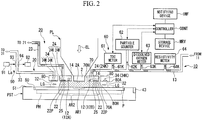
- FIG. 2 is an enlarged diagram of the principal part, showing the vicinity of the image surface side of the projection optical system PL.
- the first nozzle member 70 is an annular member arranged near the optical element 2 at the end of the projection optical system PL so as to surround the optical element 2 above the substrate P (the substrate stage PST).
- the first nozzle member 70 has a hole 70H in which the projection optical system PL (the optical element 2) can be arranged in the middle thereof.
- a bottom surface 70A of the first nozzle member 70 is provided so as to face the substrate P held on the substrate stage PST.
- the first nozzle member 70 held by the first nozzle holding member 52 is away from the projection optical system PL (the optical element 2).
- a gap is provided between the inner face of the first nozzle member 70, being an annular member, and the outer face of the optical element 2 of the projection optical system PL.
- the gap is provided for vibrationally separating the projection optical system PL and the first nozzle member 70 from each other. As a result, vibrations generated by the first nozzle member 70 can be prevented from being transmitted to the projection optical system PL side.
- the second nozzle member 80 is an annular member provided so as to surround the first nozzle member 70 above the substrate P (the substrate stage PST).
- the second nozzle member 80 has a hole 80H in which a part of the first nozzle member 70 can be arranged in the middle thereof.
- a bottom surface 80A of the second nozzle member 80 is provided so as to face the substrate P held on the substrate stage PST.
- the first nozzle member 70 held by the first nozzle holding member 52 and the second nozzle member 80 held by the second nozzle holding member 53 (see FIG. 1 ) are away from each other.
- a gap is provided between the inner face of the second nozzle member 80, being an annular member, and the outer face of the first nozzle member 70.
- the gap is provided for vibrationally separating the first nozzle member 70 and the second nozzle member 80 from each other. As a result, vibrations generated by the second nozzle member 80 can be prevented from being transmitted to the first nozzle member 70 side.
- the main column 1 supporting the first and the second nozzle members 70 and 80 via the first and the second nozzle holding members 52 and 53 and the lens-barrel board 5 supporting the lens-barrel PK of the projection optical system PL via the flange PF, are vibrationally separated from each other via the isolator 47. Accordingly, a situation where the vibrations generated by the first nozzle member 70 and the second nozzle member 80 are transmitted to the projection optical system PL is prevented. Moreover, the main column 1 supporting the first and the second nozzle members 70 and 80 via the first and the second nozzle holding members 52 and 53 and the substrate board 6 supporting the substrate stage PST are vibrationally separated from each other via the isolator 49.
- the main column 1 supporting the first and the second nozzle members 70 and 80 via the first and the second nozzle holding members 52 and 53 and the mask board 4 supporting the mask stage MST are vibrationally separated from each other via the isolator 46. Accordingly, a situation where the vibrations generated by the first nozzle member 70 and the second nozzle member 80 are transmitted to the mask stage MST via the main column 1 is prevented.
- a supply outlet 12 (12A, 12B) constituting a part of the liquid supply mechanism 10 is provided in the bottom surface 70A of the first nozzle member 70.
- the supply outlets 12A and 12B are formed substantially in a circular shape, but may be formed in an optional shape such as an elliptic shape, a rectangular shape, or a slit shape.
- the supply outlets 12A and 12B may be substantially in the same size, or may be in different sizes.
- a first collection inlet 22 constituting a part of the first liquid recovery mechanism 20 is provided outside of the supply outlet 12, relative to the projection area AR1 of the projection optical system PL.
- the first collection inlet 22 is formed in an annular shape so as to surround the projection area AR1 and the supply outlets 12A and 12B.
- the first collection inlet 22 is provided with a porous body 22P.
- the other end of the supply pipe 13 is connected to one end of a supply channel 14 formed in the first nozzle member 70.
- the other end of the supply channel 14 of the first nozzle member 70 is connected to the supply outlet 12 formed in the bottom surface 70A of the first nozzle member 70.
- the supply channel 14 formed in the first nozzle member 70 is branched somewhere so as to be connectable to the plurality of (two) supply outlets (12A and 12B) at the other ends thereof.
- the liquid supply operation of the liquid supply device 11 is controlled by the controller CONT.
- the controller CONT feeds the liquid LQ1 from the liquid supply device 11 of the liquid supply mechanism 10.
- the liquid LQ fed out from the liquid supply device 11 flows in the supply pipe 13, and then flows into the one end of the supply channel 14 formed in the first nozzle member 70.
- the liquid LQ flowing into the one end of the supply channel 14 is branched somewhere, and supplied to the space between the optical element 2 and the substrate P from the plurality of (two) supply outlets 12A and 12B formed in the bottom surface 70A of the first nozzle member 70.
- the other end of the recovery pipe 23 is connected to one end of a manifold channel 24M constituting a part of the first recovery channel 24 formed in the first nozzle member 70.
- the other end of the manifold channel 24M is formed in an annular shape as seen in plan view so as to correspond to the first collection inlet 22, and is connected to a part of an annular channel 24K constituting a part of the first recovery channel 24 connected to the first collection inlet 22.
- the liquid recovery operation of the first liquid recovery device 21 is controlled by the controller CONT.
- the controller CONT drives the first liquid recovery device 21 in the first liquid recovery mechanism 20 in order to recover the liquid LQ. Due to the drive of the first liquid recovery device 21 having the vacuum system 26, the liquid LQ on the substrate P flows into the annular channel 24K perpendicularly upward (in the +Z direction) via the first collection inlet 22 provided above the substrate P. The liquid LQ having flowed into the annular channel 24K in the +Z direction is collected in the manifold channel 24M, and then flows in the manifold channel 24M. Thereafter, the liquid LQ is sucked and recovered by the first liquid recovery device 21 via the recovery pipe 23.
- a second collection inlet 32 constituting a part of the second liquid recovery mechanism 30 is provided on the bottom surface 80A of the second nozzle member 80.
- the second collection inlet 32 is formed in the bottom surface 80A of the second nozzle member 80 opposite to the substrate P.
- the second nozzle member 80 is provided outside of the first nozzle member 70, and the second collection inlet 32 provided in the second nozzle member 80 is provided further outside than the first collection inlet 22 provided in the first nozzle member 70, relative to the projection area AR1 of the projection optical system PL.
- the second collection inlet 32 is formed in an annular shape so as to surround the first collection inlet 22.
- the other end of the recovery pipe 33 is connected to one end of the manifold channel 34M constituting a part of the second recovery channel 34 formed in the second nozzle member 80.
- the other end of the manifold channel 34M is formed in an annular shape as seen in plan view so as to correspond to the second collection inlet 32, and is connected to a part of an annular channel 34K constituting a part of the second recovery channel 34 connected to the second collection inlet 32.
- the liquid recovery operation of the second liquid recovery device 31 is controlled by the controller CONT.
- the controller CONT drives the second liquid recovery device 31 in the second liquid recovery mechanism 30 in order to recover the liquid LQ. Due to the drive of the second liquid recovery device 31 having the vacuum system 36, the liquid LQ on the substrate P flows into the annular channel 34K perpendicularly upward (in the +Z direction) via the second collection inlet 32 provided above the substrate P. The liquid LQ having flowed into the annular channel 34K in the +Z direction is collected in the manifold channel 34M, and then flows in the manifold channel 34M. Thereafter, the liquid LQ is sucked and recovered by the second liquid recovery device 31 via the recovery pipe 33.
- the controller CONT performs the liquid recovery operation (suction operation) by the second liquid recovery mechanism 30 all the time during the liquid immersion exposure and before and after the exposure of the substrate P.
- the measuring device 60 measures the property or composition (water quality) of the liquid LQ supplied by the liquid supply mechanism 10.
- the property or composition of the liquid LQ measured by the measuring device 60 is determined, taking into consideration an influence on the exposure accuracy of the exposure apparatus EX or an influence on the exposure apparatus EX itself.
- Table 1 shows one example of the property or composition of the liquid LQ and the influence on the exposure accuracy of the exposure apparatus EX or on the exposure apparatus EX itself.
- the property or composition of the liquid LQ includes; specific resistance, metal ion, total organic carbon (TOC), particle bubbles, live bacteria, dissolved oxygen (DO), and dissolved nitrogen (DN).
- the items affecting the exposure accuracy of the exposure apparatus EX or the exposure apparatus EX itself include; cloudiness of the lens (particularly, the optical element 2), generation of a water mark (remaining attachment due to solidification of impurities in the liquid, resulting from evaporation of the liquid LQ), degradation of optical performance due to a change in refractive index or light scattering, influence on a resist process (resist pattern formation), and generation of rust in respective members.
- Table 1 it is shown which property or composition affects which performance and how much, and a circle is given to an item, which is expected to be affected.
- the property or composition of the liquid LQ to be measured by the measuring device 60 is selected according to requirements from Table 1, based on the influence on the exposure accuracy of the exposure apparatus EX or the exposure apparatus EX itself. It is a matter of course that all items can be measured, or a property or composition not shown in Table 1 can be also measured.
- the measuring device 60 has a plurality of meters.
- the measuring device 60 can include, as the meter, a resistivity meter for measuring the specific resistance value, a TOC meter for measuring the total organic carbon, a particle counter for measuring foreign matter including fine particles and bubbles, a DO meter for measuring the dissolved oxygen (dissolved oxygen concentration), a DN meter for measuring the dissolved nitrogen (dissolved nitrogen concentration), a silica meter for measuring concentration of silica, and an analyzer capable of analyzing the type and amount of the live bacteria.
- the total organic carbon, particle bubbles, dissolved oxygen, and specific resistance value are selected as the items to be measured, and as shown in FIG.
- the measuring device 60 includes a TOC meter 61 for measuring the total organic carbon, a particle counter 62 for measuring foreign matter including fine particles and bubbles, a dissolved oxygen meter (DO meter) 63 for measuring the dissolved oxygen, and a resistivity meter 64 for measuring the specific resistance value.
- a TOC meter 61 for measuring the total organic carbon
- a particle counter 62 for measuring foreign matter including fine particles and bubbles
- a dissolved oxygen meter (DO meter) 63 for measuring the dissolved oxygen
- resistivity meter 64 for measuring the specific resistance value.
- the TOC meter 61 is connected to a branch pipe (branch channel) 61 K branched somewhere along the supply pipe (supply channel) 13 connected to the supply outlet 12. A part of the liquid LQ fed out from the liquid supply device 11 and flowing in the supply pipe 13 is supplied onto the substrate P from the supply outlet 12 of the first nozzle member 70, and a part of the remaining liquid LQ flows in the branch pipe 61K and into the TOC meter 61.
- the TOC meter 61 measures the total organic carbon (TOC) of the liquid LQ flowing in the branch channel formed by the branch pipe 61K.
- the particle counter 62, the dissolved oxygen meter 63, and the resistivity meter 64 are respectively connected to respective branch pipes 62K, 63K, and 64K branched somewhere along the supply pipe 13, to measure foreign matter (fine particles or bubbles), dissolved oxygen, and the specific resistance value of the liquid LQ flowing in the branch channels formed by these branch pipes 62K, 63K, and 64K.
- the silica meter and/or the live bacteria analyzer can be also connected to the branch pipe branched somewhere along the supply pipe 13.
- the branch pipes 61K to 64K respectively form an independent branch channel, and respective meters 61 to 64 are connected to respective branch channels independent of each other.
- a plurality of meters 61 to 64 is connected parallel with each other relative to the supply pipe 13 via the branch pipes 61K to 64K.
- a plurality of meters may be serially connected relative to the supply pipe 13, such that the liquid LQ branched from the supply pipe 13 is measured by a first meter, and the liquid LQ having passed the first meter is measured by a second meter.
- the same type of meters may be arranged at a plurality of positions along the supply pipe 13. According to such an arrangement, it can be specified at which position of the supply pipe 13 the property or composition of the liquid LQ has changed, thereby facilitating cause investigation of the change.
- the measuring device 60 measures the property or composition of the liquid LQ flowing in the branch channel branched somewhere along the supply channel formed by the supply pipe 13, according to an in-line method.
- the liquid LQ is supplied to the measuring device 60 all the time. Therefore, the measuring device 60 can measure the property or composition (water quality) of the liquid LQ all the time during exposure and before and after the exposure.
- the measuring device 60 can measure the liquid LQ, concurrently with the liquid immersion exposure operation to the substrate P.
- the measurement result of the measuring device 60 is output to the controller CONT.
- the controller CONT can monitor the property or composition (water quality) of the liquid LQ supplied onto the substrate P by the liquid supply mechanism 10 all the time.
- the liquid LQ is sampled, and by using an analyzer provided separately from the exposure apparatus EX, the type of the metal ion can be determined. As a result, an appropriate measure can be taken corresponding to the specified metal ion.
- the liquid LQ is sampled, and by using a total evaporative residue meter provided separately from the exposure apparatus EX, the total evaporative residue amount in the liquid LQ can be measured.
- the analyzer and the total evaporative residue meter may automatically perform sampling of the liquid LQ regularly, and inform the type of the metal ion and the measurement result of the total evaporative residue meter to the exposure apparatus EX.
- the exposure apparatus EX can compare the informed measurement result with a reference value stored beforehand, and when the measurement result exceeds the reference value, can issue a warning.
- the detector 90 detects whether the second liquid recovery mechanism 30 has recovered the liquid LQ. In the embodiment, the detector 90 detects optically whether the liquid LQ is flowing in the recovery pipe 33 of the second liquid recovery mechanism 30, to thereby detect whether the liquid LQ has been recovered via the second collection inlet 32 of the second liquid recovery mechanism 30.
- the detector 90 includes a floodlight device 91 for emitting a detection beam La, and a light receiving device 92 for receiving the detection beam La. Transmission windows 93 and 94 capable of transmitting the detection beam La are provided somewhere along the recovery pipe 33. The detector 90 irradiates the detection beam La to the transmission window 93 from the floodlight device 91.
- the detection beam La having transmitted through the transmission window 93 passes inside of the recovery pipe 33, and is then received by the light receiving device 92 via the transmission window 94.
- the light reception result of the light receiving device 92 is output to the controller CONT.
- the light receiving amount by the light receiving device 92 is different in a case where there is the liquid LQ in the recovery pipe 33 (on the optical path of the detection beams La) and in a case where there is no liquid LQ therein. Accordingly, the controller CONT can determine whether there is the liquid LQ (whether the liquid LQ is flowing) in the recovery pipe 33, that is, whether the second liquid recovery mechanism 30 has recovered the liquid LQ, based on the light reception result by the light receiving device 92.
- the detector 90 needs only to detect whether the liquid LQ has been recovered via the second collection inlet 32, and for example, may be a liquid presence sensor provided inside of the recovery pipe 33.
- the installation position of the liquid presence sensor is not limited to somewhere along the recovery pipe 33, but may be near the second collection inlet 32 of the second nozzle member 80 or inside of the second recovery channel 34.
- a flow rate controller flow element
- mass flow controller may be provided somewhere along the recovery pipe 33, to determine whether the liquid LQ has been recovered via the second collection inlet 32 based on the detection result of the mass flow controller.
- the detector 90 including the floodlight device and the light receiving device and the detector including the mass flow controller can detect the liquid recovery amount per unit time by the second liquid recovery mechanism 30.
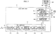
- FIG. 3 shows the configuration of the liquid supply device 11 in detail.
- the liquid supply device 11 includes the pure water production device 16 and the temperature controller 17 which controls the temperature of the liquid produced by the pure water production device 16.
- the pure water production device 16 includes a pure water production unit 161 which produces pure water of predetermined purity by purifying water including, for example, suspended matter and impurities, and an ultra-pure water production unit 162 which produces pure water of high purity (ultra-pure water) by removing impurities from the pure water produced by the pure water production unit 161.
- the pure water production unit 161 (or the ultra-pure water production unit 162) includes a liquid reforming member such as an ion exchange membrane or a particle filter, and a liquid reformer such as an ultraviolet irradiation device (UV lamp), to control the specific resistance value of the liquid, the amount of foreign matter (fine particles and bubbles), the total organic carbon, and the amount of live bacteria, to desired values by using the liquid reforming member and the liquid reformer.
- a liquid reforming member such as an ion exchange membrane or a particle filter
- a liquid reformer such as an ultraviolet irradiation device (UV lamp)
- the liquid LQ recovered by the first liquid recovery mechanism 20 and the second liquid recovery mechanism 30 is returned to the liquid supply device 11 of the liquid supply mechanism 10.
- the liquid LQ recovered by the first liquid recovery mechanism 20 and the second liquid recovery mechanism 30 is supplied to the pure water production device 16 (the pure water production unit 161) in the liquid supply device 11 via a return pipe 18.
- the return pipe 18 is provided with a valve 18B for opening and closing the flow channel of the return pipe 18.
- the pure water production device 16 purifies the liquid returned via the return pipe 18 by using the liquid reforming member and the liquid reformer, and supplies the liquid to the temperature controller 17.
- the functional liquid supply device 120 is connected to the pure water production device 16 (the pure water production unit 161) in the liquid supply device 11 via a supply pipe 19.
- the functional liquid supply device 120 can supply a functional liquid LK having a predetermined function separate from the liquid LQ for forming the liquid immersion area AR2.
- the functional liquid supply device 120 supplies a liquid (functional liquid) LK having a germicidal action.
- the supply pipe 19 is provided with a valve 19B for opening and closing the flow channel of the supply pipe 19.
- the controller CONT operates the valve 19B to close the flow channel of the supply pipe 19, to thereby suspend the supply of the functional liquid LK, when the valve 18B is operated to open the flow channel of the return pipe 18 so as to supply the liquid LQ.
- the controller CONT operates the valve 18B to close the flow channel of the return pipe 18, to thereby suspend the supply of the liquid LQ.
- the temperature controller 17 controls the temperature of the liquid (pure water) LQ produced by the pure water production device 16 and supplied to the supply pipe 13, and one end thereof is connected to the pure water production device 16 (the ultra-pure water production unit 162), and the other end thereof is connected to the supply pipe 13. After controlling the temperature of the liquid LQ produced by the pure water production device 16, the temperature controller 17 feeds the temperature-controlled liquid LQ to the supply pipe 13.
- the temperature controller 17 includes a rough temperature controller 171 which roughly controls the temperature of the liquid LQ supplied from the ultra-pure water production unit 162 in the pure water production device 16, a flow rate controller 172 referred to as a mass flow controller and provided on the downstream side (supply pipe 13 side) of the flow channel of the rough temperature controller 171 for controlling the amount of the liquid LQ per unit time to be allowed to flow to the supply pipe 13, a degasifier 173 for decreasing the concentration of the dissolved gas (dissolved oxygen concentration, dissolved nitrogen concentration) in the liquid LQ having passed the flow rate controller 172, a filter 174 for removing foreign matter (fine particles and bubbles) in the liquid LQ degasified by the degasifier 173, and a fine temperature controller 175 for finely controlling the temperature of the liquid LQ having passed the filter 174.
- a rough temperature controller 171 which roughly controls the temperature of the liquid LQ supplied from the ultra-pure water production unit 162 in the pure water production device 16
- a flow rate controller 172 referred to as a
- the rough temperature controller 171 is for controlling the temperature of the liquid LQ fed from the ultra-pure water production unit 162 with rough accuracy of about ⁇ 0.1 °C with respect to a target temperature (for example, 23 °C).
- the flow rate controller 172 is arranged between the rough temperature controller 171 and the degasifier 173, and controls the flow rate per unit time of the liquid LQ temperature-controlled by the rough temperature controller 171 with respect to the degasifier 173 side.
- the degasifier 173 is arranged between the rough temperature controller 171 and the fine temperature controller 175, specifically between the flow rate controller 172 and the filter 174, and degasifies the liquid LQ fed from the flow rate controller 172 to decrease the concentration of the dissolved gas in the liquid LQ.
- a known degasifier such as a decompressor, which degasifies by decompressing the supplied liquid LQ, can be used.
- an apparatus including a deaeration filter which performs gas-liquid separation of the liquid LQ by using a filter such as a hollow fiber membrane filter and removes the separated gas component by using solid fibers
- an apparatus including a deaeration pump which performs gas-liquid separation of the liquid LQ by using a centrifugal force and removes the separated gas component by using solid fibers
- the degasifier 173 adjusts the concentration of the dissolved gas to a desired value, by the liquid reforming member including the deaeration filter and the liquid reformer including the deaeration pump.
- the filter 174 is arranged between the rough temperature controller 171 and the fine temperature controller 175, specifically between the degasafier 173 and the fine temperature controller 175, and removes foreign matter in the liquid LQ fed from the degasifier 173.
- foreign matter particles
- the filter 174 a known filter such as the hollow fiber membrane filter and the particle filter can be used.
- the filter 174 including the liquid reforming member such as the particle filter adjusts the amount of foreign matter (fine particles and bubbles) in the liquid LQ to a tolerance or below.
- the fine temperature controller 175 is arranged between the rough temperature controller 171 and the supply pipe 13, specifically between the filter 174 and the supply pipe 13, and performs fine temperature control of the liquid LQ with high accuracy.
- the fine temperature controller 175 finely adjusts the temperature (temperature stability, temperature uniformity) of the liquid LQ fed from the filter 174 with high accuracy of about ⁇ 0.01°C to ⁇ 0.001°C relative to a target temperature.
- the fine temperature controller 175 is arranged at a position closest to the substrate P, which is an object to which the liquid LQ is supplied, and hence, the liquid LQ temperature-controlled with high accuracy can be supplied to the substrate P.
- the filter 174 is arranged between the rough temperature controller 171 and the fine temperature controller 175 in the temperature controller 17, but may be arranged at a different position in the temperature controller 17, or may be arranged outside the temperature controller 17.
- the pure water production unit 161, the ultra-pure water production unit 162, the degasifier 173, and the filter 174 respectively include the liquid reforming member and the liquid reformer, to constitute an adjusting device for regulating the water quality (property or composition) of the liquid LQ.
- These respective devices 161, 162, and 174 are respectively provided at a plurality of predetermined positions of the flow channel, in which the liquid LQ flows, of the liquid supply mechanism 10.
- one liquid supply device 11 is arranged with respect to one exposure apparatus EX (see FIG. 1 ), but the present invention is not limited thereto, and one liquid supply device 11 may be shared by a plurality of exposure apparatuses EX.
- an area (footprint) occupied by the liquid supply device 11 can be reduced.
- the pure water production device 16 and the temperature controller 17 constituting the liquid supply device 11 may be separated to share the pure water production device 16 by the plurality of exposure apparatuses EX, and the temperature controller 17 may be arranged for each exposure apparatus EX.
- the footprint can be reduced, and temperature control for each exposure apparatus can be realized.
- the liquid supply device 11 or the pure water production device 16 shared by the plurality of exposure apparatuses EX is arranged on a floor (for example, under the floor) separate from the floor where the exposure apparatus EX is arranged, the space of the clean room where the exposure apparatus EX is installed can be used more effectively.
- FIG. 4 is a plan view of the substrate stage PST as viewed from the top.
- a plurality of shot areas S1 to S24 is set on the substrate P carried (loaded) onto the substrate stage PST by an unillustrated carrier system (loader).
- An alignment mark AM is respectively added to each of the shot areas S1 to S24 on the substrate P.
- H07-176468 is arranged at a predetermined position on the substrate stage PST.
- an illuminance unevenness sensor 400 as disclosed in Japanese Unexamined Patent Application, First Publication No. S57-117238
- a space image measuring sensor 500 as disclosed in Japanese Unexamined Patent Application, First Publication No. 2002-14005
- an illuminance sensor 600 as disclosed in Japanese Unexamined Patent Application, First Publication No. H11-16816 , are provided at predetermined positions on the substrate stage PST as light measuring devices.
- the upper faces of the measuring member 300 and the light measuring devices 400, 500, and 600 are substantially flush with the upper face 51 of the substrate stage PST.
- the controller CONT Before starting exposure of the substrate P, the controller CONT measures the position relation (baseline amount) between a detection reference position of the substrate alignment system and a projection position of the pattern image of the mask M by using the substrate alignment system, the mask alignment system, and the reference member 300.
- the position of the substrate stage PST when the reference marks MFM and PFM on the reference member 300 are measured is measured by the laser interferometer 44.
- the controller CONT performs a measurement process using the respective light measuring devices 400, 500, and 600 provided on the substrate stage PST, to perform various correction processes such as lens calibration and the like based on the measurement results.
- the controller CONT performs position control of the substrate stage PST to make the projection optical system PL face the reference member 300, to thereby perform a liquid supply operation and a liquid recovery operation by the liquid supply mechanism 10 and the first liquid recovery mechanism 20, and measures the reference mark MFM on the reference member 300 via the projection optical system PL and the liquid LQ, in a state with the liquid immersion area AR2 of the liquid LQ being formed on the reference member 300.
- the controller CONT performs a measurement process via the liquid LQ in a state with the liquid immersion area AR2 of the liquid LQ being formed on the respective light measuring devices 400, 500, and 600.
- the controller CONT drives the first valve 13B to open the flow channel of the supply pipe 13, in a state with the flow channel of the connection pipe 9 being closed by the third valve 9B.
- the controller CONT drives the second valve 23B to open the flow channel of the recovery pipe 23.
- the liquid LQ in the liquid immersion area AR2 comes in contact with the bottom surface (liquid contact face) 2A of the optical element 2 of the projection optical system PL closest to the image surface and the bottom surfaces (liquid contact faces) 70A and 80A of the nozzle members 70 and 80. Furthermore, the liquid LQ comes in contact with the upper face 51 of the substrate stage PST including the measuring member 300 and the light measuring devices 400, 500, and 600.
- the controller CONT measures the alignment mark AM formed on each of the shot areas S 1 to S24 on the substrate P by using the substrate alignment system, in order to perform superposition exposure with respect to the substrate P.
- the position of the substrate stage PST when the substrate alignment system measures the alignment mark AM is measured by the laser interferometer 44.
- the controller CONT obtains position information of the shot areas S 1 to S24 relative to the detection reference position of the substrate alignment system in a coordinate system specified by the laser interferometer 44, based on the detection result of the alignment mark AM, and moves the substrate stage PST based on the position information and the baseline amount measured previously, to thereby adjust positions of the shot areas S1 and S24 with respect to the projection position of the pattern image of the mask M.
- the liquid immersion area AR2 is not formed on the substrate P (substrate stage PST), and the substrate alignment system measures the alignment mark AM in a non-liquid immersion state (in a dry state).
- the controller CONT drives the third valve 9B to open the flow channel of the connection pipe 9, in a state with the flow channel of the supply pipe 13 being closed by the first valve 13B.
- the liquid LQ flowing from the liquid supply device 11 including the temperature controller 17 to the supply pipe 13 flows to the recovery pipe 23 via the connection pipe 9.
- the liquid supply device 11 including the temperature controller 17 is driven all the time, and at the time of supplying the liquid to the image surface side of the projection optical system PL, the controller CONT drives the first valve 13B to open the flow channel of the supply pipe 13, and closes the flow channel of the connection pipe 9 by the third valve 9B, to thereby supply the liquid LQ fed from the liquid supply device 11 to the image surface side of the projection optical system PL.
- the controller CONT drives the third valve 9B to open the flow channel of the connection pipe 9, and closes the flow channel of the supply pipe 13 by the first valve 13B, so that the liquid LQ fed from the liquid supply device 11 is not supplied to the image surface side of the projection optical system PL, but is recovered by the liquid recovery device 21 via the recovery pipe 23.
- the controller CONT outputs a command signal to start liquid immersion exposure (step SA2).
- the controller CONT closes the flow channel of the connection pipe 9 by the third valve 9B, in a state that the optical element 2 of the projection optical system PL faces the predetermined area on the substrate stage PST including the substrate P, and drives the first valve 13B to open the supply pipe 13, to thereby start supply of the liquid LQ to the substrate P by the liquid supply mechanism 10.
- the controller CONT starts liquid recovery by the first liquid recovery mechanism 20, substantially simultaneously with the start of supply of the liquid LQ by the liquid supply mechanism 10.
- the liquid supply amount per unit time by the liquid supply mechanism 10 and the liquid recovery amount per unit time by the first liquid recovery mechanism 20 are approximately constant.
- the liquid LQ in the liquid immersion area AR2 formed so as to perform liquid immersion exposure with respect to the substrate P comes in contact with the bottom surface 2A of the optical element 2 and the bottom surface 70A of the first nozzle member 70.
- the liquid recovery operation (suction operation) by the first liquid recovery mechanism 20 can be performed before starting the liquid supply by the liquid supply mechanism 10 (even in the state with liquid supply being suspended).
- the second liquid recovery mechanism 30 is driven all the time, and the suction operation via the second collection inlet 32 by the second liquid recovery mechanism 30 is performed all the time.
- the controller CONT irradiates the exposure light EL onto the substrate P in a state with the projection optical system PL facing the substrate P, so that the pattern image of the mask M is exposed on the substrate P via the projection optical system PL and the liquid LQ.
- the reason why exposure is not performed until the predetermined time has passed since the release of the first valve 13B is that there is concern that bubbles generated due to the operation of the valve may be left in the liquid immersion area AR2 immediately after the release of the valve.
- the controller CONT projection-exposes the pattern image of the mask M on the substrate P via the liquid LQ between the projection optical system PL and the substrate P and the projection optical system PL, while performing recovery of the liquid LQ by the first liquid recovery mechanism 20 and moving the substrate stage PST supporting the substrate P in the X-axis direction (in the scanning direction), concurrently with supply of the liquid LQ by the liquid supply mechanism 10.
- the exposure apparatus EX in the embodiment is for projection-exposing the pattern image of the mask M, while moving the mask M and the substrate P in the X-axis direction (in the scanning direction).
- a part of the pattern image of the mask M is projected in the projection area AR1 via the liquid LQ in the liquid immersion area AR2 and the projection optical system PL, and the substrate P moves in the +X direction (or -X direction) relative to the projection area AR1 at a speed of ⁇ •V ( ⁇ is projection magnification), synchronously with the movement of the mask M in the -X direction (or +X direction) at a speed of V.
- the next shot area moves to a scanning start position by stepping movement of the substrate P, and thereafter, the scanning exposure process with respect to respective shot areas S1 to S24 is sequentially performed, while moving the substrate P according to the step and scan method.
- a shot area set in the boundary area of the substrate P for example, shot area S1, S4, S21, S24, or the like
- the liquid LQ in the liquid immersion area AR2 larger than the projection area AR1 comes in contact with the upper face 51 of the substrate stage PST.
- the property or composition (water quality) of the liquid LQ supplied on the substrate P by the liquid supply mechanism 10 is measured (monitored) by the measuring device 60 all the time.
- the measurement result of the measuring device 60 is output to the controller CONT, and the controller CONT stores the measurement result (monitor information) of the measuring device 60 in the storage device MRY (step SA3).
- the controller CONT stores the measurement result of the measuring device 60 in correspondence with the time course, in the storage device MRY.
- the controller CONT can store the measurement result of the measuring device 60 in correspondence with the time course in the storage device MRY, for example, based on the output of the timer 13T, designating the time when the first valve 13B opens the flow channel of the supply pipe 13 as a measurement starting point (reference) of the time course.
- first log information information in which the measurement result of the measuring device 60 is stored in correspondence with the time course.
- the controller CONT further stores the measurement result of the measuring device 60 in correspondence with the shot areas S 1 to S24 to be exposed, in the storage device MRY.
- the controller CONT can obtain position information of the shot areas S1 to S24 in the coordinate system specified by the laser interferometer 44, for example, based on the output of the laser interferometer 44, which measures the position of the substrate stage PST, and store the measurement result of the measuring device 60 at the time of exposing the shot area, whose position information has been obtained, in correspondence with the shot area in the storage device MRY.
- the information in which the measurement result of the measuring device 60 is stored in correspondence with the shot area is referred to as "second log information”.
- the controller CONT determines whether the measurement result of the measuring device 60 is abnormal (step SA4). The controller CONT then controls the exposure operation based on the determination result.
- the measurement result of the measuring device 60 being abnormal indicates a situation in which a measurement of respective items (specific resistance value, TOC, foreign matter, dissolved gas concentration, silica concentration, live bacteria, and the like) to be measured by the measuring device 60 is outside the tolerance, and the exposure process and the measurement process via the liquid LQ cannot be performed in a desired state.
- a tolerance as one example, 18.2 M ⁇ cm at 25°C
- metal ions such as sodium ions may be contained in a large amount in the liquid LQ.
- the liquid immersion area AR2 is formed on the substrate P with the liquid LQ containing metal ions in a large amount, there is a possibility that the metal ions in the liquid LQ infiltrate into a photosensitive material on the substrate P, and adhere on a device pattern (wiring pattern) already formed below the photosensitive material, thereby causing malfunction of the device.
- the metal ions in the liquid LQ are seen individually, when the metal ions are contained larger than a tolerance (as one example, 3 ppt, more preferably, 1 ppt), when boron is contained larger than a tolerance (as one example, 3 ppt, more preferably, 1 ppt), when silica is contained larger than a tolerance (as one example, 1 ppt, more preferably, 0.75 ppt), or when anions are contained larger than a tolerance (as one example, 400 ppt), similar contamination occurs, and malfunction of the device may be caused.
- a tolerance as one example, 3 ppt, more preferably, 1 ppt
- boron is contained larger than a tolerance
- silica as one example, 1 ppt, more preferably, 0.75 ppt
- anions are contained larger than a tolerance (as one example, 400 ppt)
- the value of total organic carbon in the liquid LQ is larger than a tolerance (as one example, 5.0 ppb, more preferably, 1.0 ppb), there is a possibility that light transmittance of the liquid LQ might be decreased.
- the exposure accuracy via the liquid LQ and the measurement accuracy by the light measuring device via the liquid LQ deteriorate.
- the light transmittance of the liquid LQ decreases, the exposure amount on the substrate P changes, thereby causing a difference in an exposure line width to be formed on the substrate P.
- the liquid LQ absorbs more optical energy by the decrease of the light transmittance, and hence, the liquid temperature increases.
- the focal length of the projection optical system PL resulting from the temperature increase.
- a decrease of the light transmittance of the liquid LQ causes a deterioration of the exposure accuracy. Therefore, taking these circumstances into consideration, a predetermined light transmittance is required for the liquid LQ, and the value of the total organic carbon (TOC) is specified corresponding thereto.
- the light transmittance required for the liquid LQ is equal to or higher than 99% per 1 mm of thickness of the liquid LQ, and the TOC required for the liquid LQ corresponding thereto is equal to or lower than 1.0 ppb.
- the amount of foreign matter including fine particles and bubbles in the liquid LQ is larger than a tolerance (abnormal) (as one example, 0.1 or more preferably 0.02 particles and bubbles having a size of 0.1 ⁇ m or larger are included in 1 milliliter), the possibility that a defect is caused in the pattern transferred to the substrate P via the liquid LQ increases.
- a tolerance as one example, 0.1 or more preferably 0.02 particles and bubbles having a size of 0.1 ⁇ m or larger are included in 1 milliliter
- the value of the dissolved gas including dissolved oxygen and dissolved nitrogen in the liquid LQ (dissolved gas concentration) is larger than a tolerance (abnormal) (as one example, 3 ppb or more preferably 1 ppb in the case of dissolved oxygen, and 3 ppm in the case of dissolved nitrogen), for example when the liquid LQ supplied onto the substrate P via the supply outlet 12 is released to the air, the possibility that bubbles are generated in the liquid LQ due to the dissolved gas in the liquid LQ increases. If bubbles are generated in the liquid LQ, the possibility that a defect is caused in the pattern transferred to the substrate P via the liquid LQ increases as well.
- a tolerance as one example, 3 ppb or more preferably 1 ppb in the case of dissolved oxygen, and 3 ppm in the case of dissolved nitrogen
- the liquid LQ is contaminated to deteriorate the light transmittance.
- a tolerance as one example, 1.0 cfu/L, more preferably, 0.1 cfu/L
- the members coming in contact with the liquid LQ are also contaminated.
- a water mark may adhere to the optical element 2 of the projection optical system PL or cloudiness may be generated.
- the controller CONT continues the liquid immersion operation (step SA5).
- the controller CONT stops the exposure operation (step SA6).
- the controller CONT can drive the first valve 13B to close the flow channel of the supply pipe 13, so as to suspend the supply of the liquid LQ.
- the controller CONT may recover the liquid LQ remaining on the substrate P by using the first nozzle member 70 and the first liquid recovery mechanism 20.
- the recovered liquid LQ may be disposed of without being returned to the liquid supply device 11, and new liquid LQ may be injected to the liquid supply device 11 so as to replace the whole liquid LQ.
- the substrate P may be carried out (unloaded) from the substrate stage PST. This can prevent an undesirable situation such as where defective shots (defective substrates) are formed in a large quantity resulting from continuance of the exposure process via the abnormal liquid LQ.
- the controller CONT informs the measurement result (monitoring result) of the measuring device 60 by the notifying device TNF (step SA7). For example, information relating to a variation amount of the TOC and the dissolved gas concentration in the liquid LQ with the lapse of time, and information relating to the TOC and the dissolved gas concentration in the liquid LQ at the time of exposing a shot area (for example, shot area S15) of the plurality of shot areas S1 to S24 can be displayed by the notifying device INF including a display device. Moreover, when determining that the measurement result of the measuring device 60 is abnormal, the controller CONT can inform that the measurement result is abnormal by the notifying device INF, for example, by issuing an alarm (a warning) from the notifying device INF.
- the controller CONT can inform that the measurement result is abnormal by the notifying device INF, for example, by issuing an alarm (a warning) from the notifying device INF.
- the controller CONT can specify in which section an abnormality has occurred based on the measurement results of these meters.
- the controller CONT then can inform that an abnormality has occurred in a certain section by the notifying device INF, to urge an investigation of the section, thereby enabling early recovery from the problem.
- the liquid supply device 11 has the liquid reforming member and the liquid reformer, and includes a plurality of adjusting devices (pure water production unit 161, ultra-pure water production unit 162, degasifier 163, and filter 164) for regulating the water quality (property or composition) of the liquid LQ.
- the controller CONT can specify at least one adjusting device from these adjusting devices based on the measurement result of the measuring device 60, and inform information relating to the specified adjusting device by the notifying device INF.
- the controller CONT displays (informs) a display of a content urging maintenance (inspection and replacement) of, for example, the deaeration filter or the deaeration pump of the degasifier 173, of the plurality of adjusting devices by the notifying device INF.
- the controller CONT displays (informs) a display of a content urging maintenance (inspection and replacement) of, for example, the pure water production device of the plurality of adjusting devices.
- the controller CONT When determining that the total organic carbon in the liquid LQ is abnormal based on the measurement result of the TOC meter of the measuring device 60, the controller CONT displays (informs) a display of a content urging maintenance (inspection and replacement) of, for example, the UV lamp of the pure water production device 16 of the plurality of adjusting devices.
- the controller CONT displays (informs) a display of a content urging maintenance (inspection and replacement) of, for example, the filter 174 or the particle filter of the pure water production device 16 of the plurality of adjusting devices.
- the controller CONT When determining that the amount of live bacteria in the liquid LQ is abnormal based on the measurement result of the live bacteria analyzer of the measuring device 60, the controller CONT displays (informs) a display of a content urging maintenance (inspection and replacement) of, for example, the UV lamp of the pure water production device 16 of the plurality of adjusting devices.
- the controller CONT displays (informs) a display of a content urging maintenance (inspection and replacement) of, for example, the filter for removing silica of the pure water production device 16 of the plurality of adjusting devices.
- the controller CONT can control the valve 18B corresponding to the water quality (property or composition) of the liquid LQ, to suspend circulation of the liquid LQ.
- the controller CONT can control so as to recover and dispose of the whole contaminated liquid LQ, and inject new liquid LQ to the liquid supply device 11 so as to replace the liquid LQ in the system by the new liquid LQ.
- the controller CONT can continue the exposure operation even when it determines that the liquid LQ has an abnormality.
- the controller CONT determines that the measurement result of the particle counter of the measuring device 60 is abnormal at the time of exposing, for example, the shot area S 15
- the controller CONT stores the abnormal measurement result of the particle counter in correspondence with the shot area S 15 as second log information in the storage device MRY.
- the controller CONT can remove the shot area S 15 in which defective pattern transfer may have occurred due to the abnormality (existence of foreign matter) of the liquid LQ, or can control so that the shot area S15 is not exposed at the time of the next superposition exposure.
- the controller CONT When the shot area S 15 is inspected and if there is no abnormality in the formed pattern, the controller CONT continues device formation using the shot area S15, without removing the shot area S15. Alternatively, the controller CONT can inform that the measurement result of the particle counter is abnormal, in correspondence with the shot area S15, by the notifying device INF. Thus, the controller CONT can display the log information by the notifying device INF, other than the configuration in which the measurement result of the measuring device 60 is displayed by the notifying device INF as the monitoring information on a real time basis.
- the controller CONT can control the exposure operation based on the measurement result of the measuring device 60. For example, as described above, before exposure of the substrate P, an exposure dose (illuminance) of the exposure light EL is measured by the light-measuring device 600 (step SA1), and after the exposure dose (illuminance) of the exposure light EL is optimally set (corrected) based on the measurement result, the exposure operation is started. However, during the exposure of the substrate P, the light transmittance of the liquid LQ may vary due to variations of the TOC in the liquid LQ.
- the exposure amount (accumulated exposure amount) on the substrate P changes, and as a result, there may be a problem such that there is a difference in the exposure line width of the device pattern to be formed in the shot areas. Therefore, a relation between the TOC in the liquid LQ and the light transmittance of the liquid LQ at that time is obtained and stored in advance in the storage device MRY, and the controller CONT controls the exposure amount based on the stored information and the measurement result of the measuring device 60 (the TOC meter 61), thereby enabling prevention of the problem.
- the controller CONT derives the light transmittance corresponding to the change of the TOC in the liquid LQ based on the stored information, and controls so as to keep the exposure amount on the substrate P constant.
- the exposure amount on the substrate P corresponding to the change of the TOC measured by the TOC meter 61, the exposure amount in the substrate (between shots) or between the substrates becomes constant, and hence, a difference in the exposure line width can be reduced.
- the relation between the TOC and the light transmittance of the liquid LQ can be obtained by the measurement process via the liquid LQ using the light-measuring device 600.
- the exposure amount on the substrate P can be controlled by using a method for controlling the energy (luminous energy) per pulse or controlling the number of pulses.
- the exposure amount on the substrate P can be controlled.
- the measuring operation using the light-measuring device 600 (step SA1) is performed during the exposure sequence, for every predetermined time interval, or for every predetermined number of substrates to be processed, and correction control of the exposure amount described above is performed between the measuring operations during the exposure sequence, and is reset for each measuring operation.
- the measuring device 60 for measuring at least one of the property and composition of the liquid LQ since the measuring device 60 for measuring at least one of the property and composition of the liquid LQ is provided, it can be determined whether the liquid LQ for forming the liquid immersion area AR2 is in a desired state (abnormal or not) based on the measurement result.
- a desired state abnormal or not
- an appropriate measure for turning the liquid LQ into the desired state can be taken quickly, or by controlling the exposure operation, deterioration of the exposure accuracy can be prevented.
- the accuracy of the measurement process using the measuring member via the liquid LQ and the light-measuring device can be maintained.
- the water quality of the liquid can be maintained, and excellent exposure accuracy and measurement accuracy via the liquid LQ can be maintained.
- the first liquid recovery mechanism 20 cannot recover all of the liquid LQ during the liquid immersion exposure of the substrate P, and the liquid LQ flows outside of the first collection inlet 22.
- the first liquid recovery mechanism 20 may have some abnormality and cannot perform the liquid recovery operation, or such a situation may occur that the liquid supply mechanism 10 has some abnormality and has a malfunction, thereby supplying the liquid LQ in a large amount and the liquid LQ cannot be recovered only by the first liquid recovery mechanism 20.
- the second liquid recovery mechanism 30 recovers the liquid LQ, which cannot be recovered by the first liquid recovery mechanism 20 and flows outside of the first collection inlet 22, via the second collection inlet 32. As shown in the diagram of FIG.
- the first liquid recovery mechanism 20 has such a configuration that large vibrations do not occur at the time of recovering the liquid LQ, since it recovers only the liquid LQ.
- the second liquid recovery mechanism 30 has such a configuration that the liquid LQ is recovered together with the ambient gas, and hence, when the liquid LQ is recovered together with the ambient gas at the time of recovering the liquid LQ from the second collection inlet 32 of the second liquid recovery mechanism 30, there is a possibility that the recovered liquid LQ strikes against the recovery channel and the inner wall of the recovery pipe in a droplet form, thereby causing vibrations in the second nozzle member 80.
- vibrations occur in the second nozzle member 80, there is a possibility that the vibrations are transmitted to the first nozzle member 70 via the lower step 8 of the main column 1, to vibrate the liquid immersion area AR2 of the liquid LQ coming in contact with the first nozzle member 70, thereby vibrating the substrate P and the substrate stage PST coming in contact with the liquid immersion area AR2.
- the vibrations occurring in the second nozzle member 80 may vibrate the projection optical system PL, to deteriorate the imaging characteristics via the projection optical system PL and the liquid LQ.
- the liquid LQ in the liquid immersion area AR2 vibrates due to the vibrations occurring in the second nozzle member 80, to thereby deteriorate the imaging characteristics due to the vibrations.
- the detector 90 detects (monitors) all the time whether the second liquid recovery mechanism 30 has recovered the liquid LQ, during the liquid immersion exposure and during the measuring operation via the liquid LQ (step SA1).
- the detection result of the detector 90 is output to the controller CONT, and the controller CONT stores the detection result of the detector 90 (monitoring information) in the storage device MRY (step SA8).
- the controller CONT stores the detection result of the detector 90 in correspondence with the time course, in the storage device MRY.
- the controller CONT can store the detection result of the detector 90 in correspondence with the time course in the storage device MRY, for example, based on the output of the timer 13T, designating the time when the first valve 13B opens the flow channel of the supply pipe 13 as the measurement starting point (reference) of the time course.
- third log information information in which the detection result of the detector 90 is stored in correspondence with the time course.
- the controller CONT further stores the detection result of the detector 90 in correspondence with the shot areas S1 to S24 to be exposed, in the storage device MRY.
- the controller CONT can obtain position information of the shot areas S1 to S24 in the coordinate system specified by the laser interferometer 44, for example, based on the output of the laser interferometer 44, which measures the position of the substrate stage PST, and store the detection result of the detector 90 at the time of exposing the shot area, whose position information has been obtained, in correspondence with the shot area in the storage device MRY.
- a timewise deviation corresponding to a distance between a detection area of the detector 90 (corresponding to the transmission windows 93 and 94) and the second collection inlet 32 occurs, between a point in time when the liquid LQ on the substrate P (shot area) is recovered via the second collection inlet 32 and a point in time when the recovered liquid LQ flows in the recovery pipe 23 and is detected by the detector 90. Accordingly, the information to be stored in the storage device MRY needs to be corrected, taking the distance into consideration. In the description below, the information in which the detection result of the detector 90 is stored in correspondence with the shot area is referred to as "fourth log information".
- the detector 90 can detect a liquid recovery amount per unit time by the second liquid recovery mechanism 30.
- the controller CONT stores the information relating to the liquid recovery amount per unit time detected by the detector 90 in the storage device MRY.
- the information relating to the liquid recovery amount per unit time can be stored in correspondence with the time course as the third log information, or in correspondence with the shot area as the fourth log information.
- the controller CONT can determine whether vibrations have occurred accompanying the liquid recovery operation of the second liquid recovery mechanism 30 at the time of exposing the substrate P (shot area), based on the detection result of the detector 90.
- the controller CONT can take an appropriate measure so as not to produce a defective shot (defective substrate) or in order to maintain excellent exposure accuracy and measurement accuracy, based on the detection result of the detector 90.
- the controller CONT determines whether the second liquid recovery mechanism 30 has recovered the liquid LQ based on the detection result of the detector 90 (step SA9). The controller CONT then controls the exposure operation based on the determination result. Specifically, when determining that the second liquid recovery mechanism 30 has not recovered the liquid LQ during the liquid immersion exposure (during supply of the liquid LQ), the controller CONT continues the liquid immersion exposure operation (step SA5). On the other hand, when determining that the second liquid recovery mechanism 30 has recovered the liquid LQ during the liquid immersion exposure (during supply of the liquid LQ), the controller CONT suspends the exposure operation (step SA6).
- the substrate P may be carried out (unloaded) from the substrate stage PST after suspension of the exposure operation. This can prevent an undesirable situation such as where defective shots (defective substrates) are formed in a large quantity resulting from continuance of the exposure process in the state that vibrations are occurring accompanying the liquid recovery operation of the second liquid recovery mechanism 30.
- the controller CONT may suspend liquid supply from the liquid supply mechanism 10.
- the controller CONT can suspend power supply, for example, to electrical equipment including an actuator (a linear motor) for driving the substrate stage PST.
- the second liquid recovery mechanism 30 has recovered the liquid LQ, there is a high possibility that the liquid LQ is flowing out. In this case, therefore, by suspending power supply to the electrical equipment, occurrence of short circuit can be prevented, even if the effluent liquid LQ splashes onto the electrical equipment.
- the controller CONT also informs the detection result (monitoring information) of the detector 90 by the notifying device INF (step SA7).
- the controller CONT may issue an alarm (a warning) indicating that the second liquid recovery mechanism 30 has recovered the liquid LQ from the notifying device INF including an alarm system.
- the controller CONT can display the information relating to the liquid recovery amount per unit time by the second liquid recovery mechanism 30, or information relating to whether the second liquid recovery mechanism 30 has recovered the liquid LQ at the time of exposing a certain shot area (for example, the shot area S15) of the plurality of shot areas S1 to S24, by the notifying device INF including the display device.
- the detector 90 can detect the liquid recovery amount per unit time by the second liquid recovery mechanism 30, the notifying device INF can also display the liquid recovery amount.
- the controller CONT can continue the exposure operation.
- the controller CONT stores the information that the second liquid recovery mechanism 30 has recovered the liquid LQ in correspondence with the shot area S15 as the fourth log information in the storage device MRY.
- the controller CONT can remove the shot area S15, in which defective pattern transfer may have occurred due to liquid recovery by the second liquid recovery mechanism 30 (occurrence of vibrations), or can take a measure so that the shot area S 15 is not exposed at the time of the next superposition exposure.
- the controller CONT When the shot area S15 is inspected and if there is no abnormality in the formed pattern, the controller CONT continues device formation using the shot area S15, without removing the shot area S15. Alternatively, the controller CONT can inform that the second liquid recovery mechanism 30 has recovered the liquid LQ at the time of exposing the shot area S 15, in correspondence with the shot area S 15 by the notifying device INF. Thus, the controller CONT can display the log information by the notifying device INF, other than the configuration in which the detection result of the detector 90 is displayed by the notifying device INF as the monitoring information on a real time basis.
- the detector 90 detects that the second liquid recovery mechanism 30 has recovered the liquid LQ during exposure of the first shot area of the plurality of shot areas S1 to S24 set on the substrate P (for example, the shot area S15), the second shot area (S16) next to the first shot area (S15) may be exposed, after waiting until the detector 90 cannot detect the liquid anymore LQ.
- the time while the second liquid recovery mechanism 30 is recovering the liquid LQ that is, the time when vibrations are occurring is long (for example, several seconds) relative to the irradiation time (for example, several hundred milliseconds) of the exposure light EL with respect to one shot area
- waiting time is provided after the exposure of the first shot area, and after waiting until the detector 90 does not detect the liquid recovered by the second liquid recovery mechanism 30 (after waiting until the vibrations subside), the exposure operation with respect to the shot area is resumed, thereby suppressing the occurrence of a defective shot.
- an acceleration sensor vibration sensor
- the second shot area can be exposed after waiting until a detection value of the vibration sensor becomes equal to or lower than a tolerance.
- the controller CONT stops the supply of the liquid LQ via the supply outlet 12 by the liquid supply mechanism 10.
- the controller CONT then recovers the liquid LQ remaining on the substrate P and the substrate stage PST via the first collection inlet 22 of the first liquid recovery mechanism 20 and the second collection inlet 32 of the second liquid recovery mechanism 30.
- the substrate P subjected to the exposure process is unloaded from the substrate stage PST (step SA10).
- the controller CONT drives the third valve 9B to open the flow channel of the connection pipe 9, in the state with the flow channel of the supply pipe 13 being closed by the first valve 13B. This allows the liquid LQ flowing from the liquid supply device 11 including the temperature controller 17 to the supply pipe 13 to flow to the recovery pipe 23 via the connection pipe 9, and when it is not necessary to supply the liquid, the liquid LQ fed from the liquid supply device 11 is not supplied onto the substrate P, but is recovered by the liquid recovery device 21 via the recovery pipe 23.
- the exposed substrate P is unloaded from the substrate stage PST, a new substrate P to be exposed is loaded on the substrate stage PST. Then, the above described exposure sequence is repeated.
- the first to the fourth log information is accumulated and stored in the storage device MRY.
- the first and the second log information relating to the property or composition (water quality) of the liquid LQ, and the third and the fourth log information relating to the liquid recovery operation (recovery situation) by the second liquid recovery mechanism 30 are stored in the storage device MRY.
- analysis of defective exposure (error) and control of the exposure apparatus EX can be performed (step SA11).
- respective adjusting devices constituting the liquid supply device 11 can be maintained (inspected and replaced) at an optimum timing.
- the frequency of inspection and replacement can be set optimally corresponding to the respective adjusting devices. For example, when it is found from the first log information that the measurement value of the particle counter deteriorates with the lapse of time, optimal replacement timing (replacement frequency) of the particle filter can be predicted and optimally set based on the degree of changes of the measurement value with the lapse of time.
- the performance of the particle filter to be used can be optimally set based on the first log information.
- a high-performance particle filter is used, and when the measurement value of the particle counter does not change largely, a relatively low-performance (low price) particle filter can be used to reduce the cost.
- the occurrence of a problem such as where excessive (unnecessary) maintenance is performed, thereby decreasing the operating ratio of the exposure apparatus, or on the contrary, maintenance is neglected, and the liquid LQ in the desired state cannot be supplied, can be prevented.
- the first log information is water quality information associated with the time course, it can be specified from which point in time the water quality has deteriorated. Accordingly, the cause of generation of defective exposure can be analyzed in correspondence with the time course.
- the cause of problems such as defective exposure (pattern defect) can be analyzed by using the first and the second log information.
- the cause of the problem can be analyzed and specified by collating the inspection result with the first and the second log information, to perform analysis.
- the second log information is referred to, and when the measurement value of the particle counter at the time of exposing the lot (or the shot area) shows an abnormal value, it can be analyzed that the cause of the pattern defect is foreign matter (fine particles and bubbles).
- the cause of the problem can be specified.
- an appropriate measure can be taken, such as replacing the particle filter or the deaeration filter so as not to generate a pattern defect.
- the cause of various problems can be specified.
- the controller CONT also controls the exposure operation and the measurement operation based on the first and the second log information. For example, when it is determined that the value of TOC deteriorates with the lapse of time based on the first log information, the exposure apparatus EX controls the exposure amount corresponding to the time course based on a value (variation) corresponding to the time course of the TOC stored as the first log information, thereby making the exposure amount constant between substrates P, to reduce a difference in the exposure line width.
- a method for controlling the energy (luminous energy) per pulse, a method for controlling the number of pulses, or a method for controlling the scanning speed of the substrate P can be employed.
- the cause of problems such as defective exposure (a difference in line width) can be also analyzed by using the third and the fourth log information. If vibrations are generated accompanying the liquid recovery by the second liquid recovery mechanism 30, a difference (including a difference in line width in the substrate and a difference in line width in the shot) likely occurs in the exposure line width of the pattern. Specifically, after the exposure of the substrate P, when the substrate P is inspected in a certain inspection process, which is post-processing thereof, the cause of the problem can be analyzed and specified by collating the inspection result with the third and the fourth log information, to perform analysis.
- the fourth log information is referred to, and when the second liquid recovery mechanism 30 recovers the liquid LQ at the time of exposing the lot (or the shot area), it can be analyzed that the cause of the pattern defect is vibrations generated accompanying the liquid recovery operation by the second liquid recovery mechanism 30.
- the detection result of the detector 90 liquid recovery state of the second liquid recovery mechanism 30
- the change in the line width the influence of the liquid recovery operation by the second liquid recovery mechanism 30 on the exposure accuracy is determined, and the cause of the problem (difference in line width) can be specified.
- the information relating to the liquid recovery operation (recovery situation) of the second liquid recovery mechanism 30 is stored as the third and the fourth log information, and by analyzing the correlation between the detection result of the detector 90 (the liquid recovery situation of the second liquid recovery mechanism 30) and the accuracy of synchronous movement and the focus accuracy, the influence of the liquid recovery operation by the second liquid recovery mechanism 30 on the exposure accuracy is determined, whereby the cause of the problem (deterioration of the accuracy of synchronous movement and the focus accuracy) can be specified.
- an appropriate measure can be taken such that the liquid supply amount per unit time by the liquid supply mechanism 10 is changed, the liquid recovery amount per unit time by the first liquid recovery mechanism 20 is changed, or the moving speed (scanning speed) of the substrate P is changed, so as not to generate a difference in the line width or the like, more specifically, so that the second liquid recovery mechanism 30 does not recover the liquid LQ,
- the third log information is the information relating to the liquid recovery operation of the second liquid recovery mechanism 30 associated with the time course, it can be specified at which point in time the liquid LQ has been recovered by the second liquid recovery mechanism 30. Therefore, the cause of generation of defective exposure can be analyzed associated with the time course.
- the controller CONT can take a measure such that the particular shot area is removed, or the shot area is not exposed at the time of next superposition exposure.
- the controller CONT can output an instruction to perform more detailed inspection of the particular shot area than usual, to an inspection device which performs the inspection process.
- the influence of the liquid recovery operation by the second liquid recovery mechanism 30 on the exposure accuracy can be determined by analyzing the correlation between the liquid recovery situation of the second liquid recovery mechanism 30 and changes in the line width, or the correlation between the accuracy of synchronous movement and the focus accuracy.
- the pattern transfer accuracy onto the substrate P when the second liquid recovery mechanism 30 recovers the liquid LQ can be obtained beforehand.
- the degree of deterioration of the pattern transfer accuracy changes corresponding to the liquid recovery amount per unit time by the second liquid recovery mechanism 30, pattern transfer accuracy corresponding to the liquid recovery amount can be obtained beforehand.
- the controller CONT can predict the pattern transfer accuracy in a shot area on the substrate P, to which the pattern of the mask M has been transferred when the second liquid recovery mechanism 30 recovers the liquid LQ, based on the detection result of the detector 90 and the memory information stored in the storage device MRY. Then the controller CONT can inform the predicted result by the notifying device INF. As a result, after the substrate P has been exposed, when it is predicted that the predicted pattern transfer accuracy is equal to or higher than the tolerance, thereby causing a defective shot, the controller CONT can take a measure such as removing the defective shot without going through the inspection process.
- the supplied liquid LQ may be sampled at a predetermined timing, and the liquid LQ may be measured (analyzed) by using a measuring device (analyzer) provided separately from the exposure apparatus EX.
- a measuring device analyzer
- the liquid LQ may be sampled at a predetermined timing, and the liquid LQ may be measured by using the measuring device provided separately from the exposure apparatus EX.
- a valve may be provided for each of the branch pipes 61K to 63K, and the valve may be operated to allow the liquid LQ flowing in the supply pipe 13 to flow into the measuring device 60 at a predetermined timing, so as to measure the liquid LQ intermittently.
- measurement by the measuring device 60 can be stabilized by supplying the liquid LQ flowing in the supply pipe 13 to the measuring device 60 all the time to measure the liquid continuously.
- the branch pipes 61K, 62K, 63K, and 64K are connected to the connection pipe 13 between the liquid supply device 11 and the first nozzle member 70, and the measuring device 60 measures the liquid LQ branched from the supply pipe 13.
- the branch pipes are provided as close as possible to the first nozzle member 70 (the supply outlet 12).
- the branch pipes 61K, 62K, 63K, and 64K function as sampling ports for sampling the liquid LQ flowing in the supply pipe 13, and the measuring device 60 measures the liquid LQ sampled by using the branch channel provided somewhere in the supply pipe 13 between the temperature controller 17 and the first nozzle member 70.
- the sampling port may be fitted to, for example, near the supply outlet 12 of the first nozzle member 70, so that the measuring device 60 measures the liquid LQ flowing near the supply outlet 12.
- the sampling port may be provided between the pure water production device 16 and the temperature controller 17, immediately after the temperature controller 17 on the downstream side, or the sampling port may be provided in the connection pipe 9, so that the measuring device 60 measures the liquid LQ flowing in the connection pipe 9.
- the measuring device 60' may measure the liquid LQ recovered by the first liquid recovery mechanism 20.
- a meter 65 of the measuring device 60' is connected to a branch pipe 65K branched from somewhere along the recovery pipe 23 of the first liquid recovery mechanism 20. That is, in the example shown in FIG. 7 , the sampling port of the measuring device 60' is provided in the recovery pipe 23.
- the meter 65 measures the liquid LQ coming in contact with the substrate P.
- the liquid LQ coming in contact with the substrate P may contain eluates from a protection film referred to as a photoresist of a top coat provided on the substrate P.
- the meter 65 can measure the property and composition of the liquid LQ containing these eluates.
- the controller CONT can store the measurement result of the meter 65 in correspondence with the time course or the shot area in the storage device MRY as log information.
- the controller CONT can determine a change amount of the eluates with the lapse of time based on the log information. When the change amount considerably increases with the lapse of time, it can be determined that the photoresist is soluble relative to the liquid LQ. Furthermore, the controller CONT can determine acidity of the recovered liquid LQ. The liquid LQ having high acidity causes corrosion (rust) of members coming in contact with the liquid LQ, such as the recovery pipe 23. Therefore, the controller CONT informs a measurement result (log information) of the property or composition of the recovered liquid LQ, for example, by the notifying device INF, so as to take a measure such as urging review (change) of the type of the photoresist to be used.
- a measurement result log information
- the notifying device INF so as to take a measure such as urging review (change) of the type of the photoresist to be used.
- the controller CONT informs the measurement result (log information) of the property or composition of the recovered liquid LQ, for example, by the notifying device INF, so as to take a measure such as urging replacement or cleaning of the porous body 22P.
- a measuring device 60" may be provided on the substrate stage PST.
- the measuring device 60" includes a meter 66 embedded in the substrate stage PST, and a sampling port (hole) 67 provided on the upper face 51 of the substrate stage PST.
- the meter 66 measures the liquid LQ
- the liquid immersion area AR2 of the liquid LQ is formed on the image surface side of the projection optical system PL
- the liquid immersion area AR2 and the substrate stage PST are relatively moved so as to arrange the liquid immersion area AR2 above the sampling port 67, and the liquid LQ is allowed to flow to the sampling port 67.
- the meter 66 measures the liquid LQ obtained via the sampling port 67.
- the controller CONT can supply a functional liquid LK from the liquid supply mechanism 10 to respective members coming in contact with the liquid LQ forming the liquid immersion area AR2, to clean these members.
- the liquid LQ is not in a desired state but is contaminated, for example, lots of live bacteria are contained in the liquid LQ, there is a possibility of contaminating the respective members coming in contact with the liquid LQ, specifically, the liquid contact face 70A of the first nozzle member 70, the liquid contact face 80A of the second nozzle member 80, the supply channel 14 and the first recovery channel 24 as inner channels of the first nozzle member 70, the second recovery channel 34 as the inner channel of the second nozzle member 80, the supply pipe 13 as a channel forming member coming in contact with the first nozzle member 70, the recovery pipe 33 connected to the second nozzle member 80, the liquid contact face 2A of the optical element 2, the upper face 51 of the substrate stage PST, and the measuring member 300 and the light measuring devices 400, 500, and 600 on the substrate stage PST.
- the controller CONT supplies a functional liquid LK having a bactericidal action to the above described respective members from the functional liquid supply device (cleaning device) 120 constituting a part of the liquid supply mechanism 10, to thereby clean the respective members.
- the functional liquid supply device 120 supplies the functional liquid LK having the bactericidal action.
- the functional liquid LK having the bactericidal action for example, hydrogen peroxide solution or liquid containing ozone can be mentioned.
- the controller CONT drives the valve 19B provided in the supply pipe 19 connecting the functional liquid supply device 120 and the liquid supply device 11, to open the flow channel of the supply pipe 19, and closes the flow channel of the return pipe 18 by the valve 18B.
- the functional liquid LK having the bactericidal action is supplied from the functional liquid supply device 120 to the liquid supply device 11 (step SB1).
- the functional liquid LK supplied from the functional liquid supply device 120 flows in the liquid supply device 11 including the pure water production device 16 and the temperature controller 17, then flows in the supply pipe 13 and the supply channel 14 of the first nozzle member 70, and is supplied to the image surface side of the projection optical system PL via the supply outlet 12.
- the functional liquid supply device 120 supplies the functional liquid LK to the flow channels (the supply pipe 13, the supply channel 14, and the like) constituting the liquid supply mechanism 10, through which the liquid LQ flows, to thereby clean these flow channels.
- the member needs to be removed beforehand. Specifically, since the ion exchange membrane mounted on the pure water production unit 161 will be broken if the hydrogen peroxide solution passes therethrough, the ion exchange membrane is removed beforehand.
- the controller CONT instructs to remove the ion exchange membrane by the notifying device INF before driving the valve 19B.
- the functional liquid supply device 120 When the functional liquid supply device 120 is supplying the functional liquid LK to the image surface side of the projection optical system PL, a dummy substrate is held on the substrate stage PST (the substrate holder PH).
- the dummy substrate has substantially the same size and shape as those of the substrate P for device production.
- the dummy substrate has liquid repellency with respect to the functional liquid LK.
- the dummy substrate need not have liquid repellency with respect to the functional liquid LK.
- the functional liquid LK fed from the functional liquid supply device 120 is supplied onto the dummy substrate from the supply outlet 12, to form the liquid immersion area on the image surface side of the projection optical system PL.
- the first liquid recovery mechanism 20 and the second liquid recovery mechanism 30 are performing the liquid recovery operation (suction operation), similar to at the time of the liquid immersion exposure operation. Therefore, the functional liquid LK in the liquid immersion area formed on the image surface side of the projection optical system PL is recovered via the first collection inlet 22, flows in the first recovery channel 24 and the recovery pipe 23, and is then recovered by the first liquid recovery device 21.
- the controller CONT increases the supply amount of the functional liquid per unit time from the functional liquid supply device 120, or decreases the recovery amount of the functional liquid per unit time by the first liquid recovery mechanism 20, to thereby increase the liquid immersion area of the functional liquid LK, and the functional liquid LK in the liquid immersion area is recovered via the second collection inlet 32 of the second liquid recovery mechanism 30.
- the functional liquid LK recovered via the second collection inlet 32 flows in the second recovery channel 34 and the recovery pipe 33, and is recovered by the second liquid recovery device 31.
- the functional liquid LK flows in the flow channels of the first and the second liquid recovery mechanisms 20 and 30, these flow channels are cleaned.
- the functional liquid LK recovered via the first and the second collection inlets 22 and 33 may be recovered by another recovery device separate from the first and the second liquid recovery devices 21 and 31, instead of being recovered by the first and the second liquid recovery devices 21 and 31.
- the recovered functional liquid LK may be returned to the liquid supply device 11 again, or may be disposed of.
- the liquid LQ is replaced by the functional liquid LK (step SB2).
- the functional liquid LK in the liquid immersion area formed on the image surface side of the projection optical system PL also comes in contact with the liquid contact face 2A of the optical element 2 and the liquid contact faces 70A and 80A of the nozzle members 70 and 80, and hence, these liquid contact faces 2A, 70A and 80A can be cleaned.
- the substrate stage PST in the XY directions relative to the liquid immersion area in a state with the liquid immersion area of the functional liquid LK being formed, the upper face 51 of the substrate stage PST, the measuring member 300, and the light measuring devices 400, 500, and 600 provided on the substrate stage PST can be cleaned (step SB3).
- the respective members can be efficiently cleaned simultaneously.
- the functional liquid LK As the cleaning procedure using the functional liquid LK, after the functional liquid LK is supplied from the functional liquid supply device 120, supply and recovery operations of the functional liquid LK are continued for a predetermined time in the same procedure as at the time of the liquid immersion exposure operation, to thereby form the liquid immersion area of the functional liquid LK on the image surface side of the projection optical system PL.
- the functional liquid LK After heating the functional liquid LK, the functional liquid LK may be allowed to flow to the liquid supply mechanism 10 and the flow channels of the first and the second liquid recovery mechanisms 20 and 30. After a predetermined time has passed, the supply and recovery operations of the functional liquid LK are stopped. In this state, the functional liquid LK is held on the image surface side of the projection optical system PL, to form an immersion state.
- the controller CONT operates the valves 19B and 18B again to switch the piping channels, so as to supply the liquid LQ from the liquid supply device 11 to the supply pipe 13 (step SB4).
- the supply and recovery operations of the liquid LQ are performed for a predetermined time by the liquid supply mechanism 10 and the first and the second liquid recovery mechanisms 20 and 30, to thereby form the liquid immersion area of the liquid LQ on the image surface side of the projection optical system PL.
- the liquid LQ flows in respective flow channels of the liquid supply mechanism 10, the first liquid recovery mechanism 20, and the second liquid recovery mechanism 30, and the functional liquid LK remaining in the flow channels is washed away by the liquid LQ (step SB5).
- the liquid contact face 2A of the optical element 2 and the liquid contact faces 70A and 80A of the nozzle members 70 and the second nozzle member 80 are also cleaned by the liquid immersion area of the pure water.
- the functional liquid LK remaining on the upper face 51 of the substrate stage PST, the measuring member 300, and the light measuring devices 400, 500, and 600, with which the functional liquid LK has come in contact are washed away by the liquid LQ.
- the liquid LQ is measured by the measuring device 60, whereby it can be confirmed whether the cleaning process has been performed satisfactorily, that is, whether the liquid LQ is in the desired state.
- the upper face 51 of the substrate stage PST has liquid repellency in order to suppress the outflow of the liquid LQ to the outside of the substrate P (outside of the upper face 51) during liquid immersion exposure, and to prevent an undesirable situation where the liquid LQ can be smoothly recovered after the liquid immersion exposure and the liquid LQ remains on the upper face 51.
- the upper face 51 is formed of a material having liquid repellency such as polytetrafluoroethylene (Teflon (registered trademark)).
- the upper face 51 may be made liquid-repellent by performing liquid-repellent processing, for example, applying a liquid-repellent material, such as a fluororesin material such as polytetrafluoroethylene, an acrylic resin material, or a silicon resin material, or by affixing a thin film formed of the above liquid-repellent materials.
- a liquid-repellent material such as a fluororesin material such as polytetrafluoroethylene, an acrylic resin material, or a silicon resin material, or by affixing a thin film formed of the above liquid-repellent materials.
- the optical element 2 is formed of fluorite or quartz and the liquid contact face 2A of the optical element 2 has a lyophilic property. Moreover, the liquid contact face 70A of the first nozzle member 70 (and the liquid contact face 80A of the second nozzle member 80 according to circumstances) also has the lyophilic property. Since these liquid contact faces have the lyophilic property, the liquid can be satisfactorily held on the image surface side of the projection optical system PL, thereby forming the liquid immersion area. When lyophilic processing is performed with respect to the liquid contact faces 2A and 70A to make these faces lyophilic, for example, lyophilic materials such as MgF 2 , Al 2 O 3 , or SiO 2 can be adhered (applied) thereto.
- lyophilic materials such as MgF 2 , Al 2 O 3 , or SiO 2 can be adhered (applied) thereto.
- the liquid LQ in the embodiment is water having large polarity
- a material having a large molecular structure such as alcohol as the lyophilic processing (hydrophilic processing)
- hydrophilic processing hydrophilic processing
- the functional liquid LK is formed of a material, which does not affect these liquid contact faces.
- the functional liquid LK is formed of a material which does not affect the upper face 51 of the substrate stage PST and the liquid contact faces 2A, 70A, and 80A.
- the liquid immersion area of the functional liquid LK can be formed on the image surface side of the projection optical system PL, in a state with the dummy substrate covering the whole area of the upper face 51 of the substrate stage PST, mounted on the substrate stage PST.
- the operation of the liquid supply mechanism 10 including the functional liquid supply device 120 is controlled based on the measurement result of the measuring device 60, to perform the cleaning process.
- the cleaning process is performed, for example, at intervals of predetermined time (for example, every month, or every year), without depending on the measurement result of the measuring device 60.
- the liquid LQ the first nozzle member 70, the optical element 2, and the like
- not only the contaminated liquid LQ, but also impurities floating in the air may adhere to these members, thereby contaminating the members.
- by performing the cleaning process at intervals of predetermined time without depending on the measurement result of the measuring device 60, contamination of the members, and contamination of the liquid LQ coming contact with the members can be prevented.
- a cleaning liquid having a bactericidal action is supplied as the functional liquid LK, however, foreign matter adhering to the members including the supply pipe 13 and the recovery pipe 23 can be removed by flushing hydrogen water as the functional liquid LK.
- the functional liquid hydrogen water
- carbon dioxide water as the functional liquid, electrical conductivity of the member including the supply pipe 13 and the recovery pipe 23 can be controlled.
- the process for flushing the functional liquid LK (cleaning process) and the liquid immersion exposure process are executed separately.
- the functional liquid LK can be used as the liquid for the liquid immersion exposure
- the liquid immersion area AR2 for performing liquid immersion exposure can be formed by the functional liquid LK. In this case, the cleaning process and the liquid immersion exposure process are performed simultaneously.
- the functional liquid supply device 120 supplies the functional liquid LK to the pure water production device 16.
- the configuration may be such that the functional liquid supply device 120 is connected to between the pure water production device 16 and the temperature controller 17, and a valve for preventing the functional liquid LK from flowing backward to the pure water production device 16 is provided, so as to supply the functional liquid LK to the downstream of the temperature controller 17. According to this configuration, at the time of supplying the functional liquid LK, the ion exchange membrane of the pure water production device 16 need not be removed.
- the liquid LQ in the above embodiments is constituted by pure water.
- Pure water has the advantage that it is easily available in bulk in, e.g., semiconductor manufacturing factories and also the advantage that it does not adversely affect photoresist on the substrate P, optical elements (lenses), etc. Further, pure water does not adversely affect the environment and contains scarcely any impurities; thus, the effect that it cleans the surface of the substrate P and the surface of the optical element provided at the end portion of projection optical system PL can be expected.
- the exposure apparatus may include an ultra-pure water production device.
- the refractive index n of pure water (water) relative to the exposure light EL having a wavelength of about 193 nm is approximately 1.44, and thus when the ArF excimer laser light (wavelength of 193 nm) is used as the light source of the exposure light EL, the wavelength of the exposure light is effectively shortened, on the substrate P, as if multiplied by 1/n, i.e., effectively becomes approximately 134 nm, and thus, a high resolution can be obtained.
- the numerical aperture of the projection optical system PL can be further increased; which also improves the resolution.
- the numerical aperture NA of the projection optical system PL may become 0.9 to 1.3.
- the numerical aperture NA of the projection optical system PL becomes large, random-polarized light conventionally used as the exposure light may, because of its polarization effect, adversely affect the imaging performance; thus, a polarized light illumination method is preferably used.
- S polarization components TE polarization components
- diffracted lights of the polarization components having the polarization direction in line with the longitudinal direction of the line pattern are emitted in large quantities from the pattern of the mask (reticle).
- H06-188169 and the like are appropriately combined, it works more effectively.
- the combination of the linearly polarized light illumination system and the dipole illumination system is particularly effective, when the periodic direction of the line-and-space pattern is limited to a predetermined one direction, or when the hole patterns are overcrowded along a predetermined one direction.
- the depth of focus (DOF) can be increased by about 150 nm, more than for a case of using random-polarized light.
- the mask M acts as a polarizing plate due to a wave guide effect depending on the structure of the mask M (for example, fineness of the pattern and thickness of chrome), and hence, the diffracted lights from the S polarization components (TE polarization components) are emitted from the mask M in larger quantities than the diffracted light from P polarization components (TM polarization components), which decreases contrast.
- TE polarization components the diffracted lights from the S polarization components
- TM polarization components diffracted light from P polarization components
- the halftone-type phase shift mask (a pattern having a half pitch of about 63 nm) having a transmittance of 6% is illuminated by using both the polarized light illumination system which linearly polarizes in the tangential direction of the circle centering on the optical axis and the annular illumination system (zone ratio: 3/4)
- the depth of focus (DOF) can be increased by about 250 nm, more than for a case of using the random-polarized light.
- the depth of focus (DOF) can be increased by about 100 nm.
- the optical element (lens) 2 is attached to the end of the projection optical system PL, and with the aid of this lens, the optical characteristics of the projection optical system PL, for example, aberration (spherical aberration, coma aberration, etc.) can be adjusted.
- the configuration is such that the optical path space on the emission side of the optical element 2 of the projection optical system PL is filled with the liquid LQ to expose the substrate P.
- both of the optical path space on the incident side and the optical path space on the emission side of optical element 2 of the projection optical system PL maybe filled with the liquid LQ.
- a part or all of the matters described in the above embodiments may be applied to the liquid LQ to be filled in the optical path space on the incident side of the optical element 2.
- the property or composition of the liquid LQ to be supplied to the incident side of the optical element 2 can be controlled as in the liquid LQ to be supplied to the emission side.
- a control value of the property or composition of the liquid LQ is made different between the incident side and the emission side of the optical element 2, taking into consideration a difference of influence on the exposure performance, so as to control the property or composition of the liquid LQ independently.
- the functional liquid LK may be introduced also to the incident side of the optical element 2, so as to perform cleaning and discharge.
- an optical plate used for the adjustment of the optical characteristics of the projection optical system PL may be utilized.
- a plane parallel plate that can transmit exposure light EL may be utilized.
- the optical element may be rigidly fixed so as not to move due to the pressure, instead of making the optical element replaceable.
- the configuration is such that the space between the projection optical system PL and the surface of the substrate P is filled with the liquid LQ, however the configuration may also be, for example, such that the space is filled with the liquid LQ in the state that a cover glass constituted by a plane parallel plate is attached to the surface of the substrate P
- the liquid LQ is water, but the liquid LQ may be a liquid other than water.
- the light source of the exposure light EL is an F 2 laser
- the F 2 laser light does not transmit through water, and thus, as the liquid LQ, a fluorofluid that can transmit the F 2 laser light, such as perfluoropolyether (PFPE) or fluorochemical oil, may be used.
- PFPE perfluoropolyether
- a thin film is formed on a portion coming in contact with liquid LQ with a material having a molecular structure having small polarity, for example, containing fluorine, to perform lyophilic processing.
- liquid LQ a material (e.g., cedar oil) that can transmit the exposure light EL, has a high refractive index as high as practicable, and does not affect the projection optical system PL and the photoresist applied to the surface of substrate P can also be used. Also in this case, the surface treatment is applied in accordance with the polarity of the liquid LQ to be used.
- cedar oil e.g., cedar oil
- the substrate P of each of the above-described embodiments not only a semiconductor wafer for manufacturing a semiconductor device, but also a glass substrate for a display device, a ceramic wafer for a thin film magnetic head, a master mask or reticle (synthetic quartz or silicon wafer), etc. used in the exposure apparatus can be used.
- the exposure apparatus EX in addition to a scan type exposure apparatus (scanning stepper) of a step-and-scan method in which while synchronously moving the mask M and the substrate P, the pattern of the mask M is scan-exposed, a step-and-repeat type projection exposure apparatus (stepper) in which the pattern of the mask M is exposed in a batch in the state with the mask M and the substrate P being stationary, and the substrate P is successively moved stepwise can be used.
- the present invention can be applied to an exposure apparatus EX of a method in which a reduced image of a first pattern is exposed in a batch on the substrate P by using the projection optical system (for example, a refractive projection optical system having, for example, a reduction magnification of 1/8, which does not include a reflecting element), in the state with the first pattern and the substrate P being substantially stationary.
- the present invention can be also applied to a stitch type batch exposure apparatus in which after the reduced image of the first pattern is exposed in a batch, a reduced image of a second pattern is exposed in a batch on the substrate P, partially overlapped on the first pattern by using the projection optical system, in the state with the second pattern and the substrate P being substantially stationary.
- the stitch type exposure apparatus a step-and-stitch type exposure apparatus in which at least two patterns are transferred onto the substrate P in a partially overlapping manner, and the substrate P is sequentially moved, can be used.
- the present invention can be applied to a twin stage type exposure apparatus as disclosed in Japanese Unexamined Patent Application, First Publication No. H10-163099 , Japanese Unexamined Patent Application, First Publication No. H10-214783 , and Published Japanese Translation No. 2000-505958 of PCT International Application.
- an exposure apparatus in which the liquid is locally filled in the space between the projection optical system PL and the substrate P is used.
- the present invention can be also applied to a liquid immersion exposure apparatus in which a stage holding a substrate to be exposed is moved in a liquid tank, as disclosed in Japanese Unexamined Patent Application, First Publication No. H06-124873 .
- the present invention is not limited to an exposure apparatus which exposes a semiconductor pattern onto the substrate P, for manufacturing semiconductor devices, but can also be applied to a variety of exposure apparatuses, e.g., an exposure apparatus for manufacturing liquid crystal display devices or displays, an exposure apparatus for manufacturing thin film magnetic heads, and an exposure apparatus for manufacturing image pickup devices (CCD), reticles or masks.
- an exposure apparatus for manufacturing liquid crystal display devices or displays e.g., an exposure apparatus for manufacturing liquid crystal display devices or displays, an exposure apparatus for manufacturing thin film magnetic heads, and an exposure apparatus for manufacturing image pickup devices (CCD), reticles or masks.
- CCD image pickup devices
- each of the substrate stage PST and the mask stage MST may be either of a type moving along a guide, or of a guideless type having no guide.
- a planar motor in which by making a magnet unit in which magnets are two-dimensionally arranged and an armature unit in which coils are two-dimensionally arranged face each other, each of the substrate stage PST and the mask stage MST is driven by an electromagnetic force, may be used.
- either one of the magnet unit and the armature unit is attached to the stage PST and the stage MST, and the other unit is attached to the moving surface side of the stage PST or the stage MST
- a reaction force generated by the movement of the substrate stage PST may be, as described in Japanese Unexamined Patent Application, First Publication No. H08-166475 ( U.S. Patent No. 5,528,118 ), mechanically released to the floor (earth) by use of a frame member so that the force does not transmit to the projection optical system PL.
- a reaction force generated by the movement of the mask stage MST may be, as described in Japanese Unexamined Patent Application, First Publication No. H08-330224 ( U.S. Patent Application Serial No. 08/416,558 ), mechanically released to the floor (earth) by use of a frame member so that the force does not transmit to the projection optical system PL.
- the exposure apparatus EX is built by assembling various subsystems, including each element listed in the claims of the present application, in such a manner that prescribed mechanical accuracy, electrical accuracy, and optical accuracy are maintained.
- every optical system is adjusted to achieve its optical accuracy
- every mechanical system is adjusted to achieve its mechanical accuracy
- every electrical system is adjusted to achieve its electrical accuracy.
- the process of assembling each subsystem into the exposure apparatus includes mechanical interfaces, electrical circuit wiring connections, and air pressure plumbing connections between each subsystem. Needless to say, there is also a process where each subsystem is assembled prior to the assembling of the exposure apparatus from the various subsystems. On completion of the process of assembling the various subsystems in the exposure apparatus, overall adjustment is performed to make sure that the above accuracies are maintained in the complete exposure apparatus. Additionally, it is desirable to manufacture the exposure apparatus in a clean room, in which the temperature, purity, etc. are controlled.
- micro devices such as semiconductor devices are manufactured by a series of steps, including: a step 201 in which the micro device's function and performance design is performed; a step 202 in which a mask (reticle) is manufactured based on the design step; a step 203 in which a substrate, the device's base material, is manufactured; a substrate process step 204 in which the mask pattern is exposed onto the substrate by the exposure apparatus EX according to the above-described embodiments; a device assembly step 205 (including the dicing process, bonding process, and packaging process); and an inspection step 206.
- a step 201 in which the micro device's function and performance design is performed
- a step 202 in which a mask (reticle) is manufactured based on the design step
- a step 203 in which a substrate, the device's base material, is manufactured
- a substrate process step 204 in which the mask pattern is exposed onto the substrate by the exposure apparatus EX according to the above-described embodiments
- a device assembly step 205 including the
Applications Claiming Priority (3)
| Application Number | Priority Date | Filing Date | Title |
|---|---|---|---|
| JP2004171115 | 2004-06-09 | ||
| EP05749073.2A EP1783821B1 (fr) | 2004-06-09 | 2005-06-07 | Système d'exposition et méthode de production du dispositif |
| EP15166205.3A EP2966670B1 (fr) | 2004-06-09 | 2005-06-07 | Appareil d'exposition et procédé de fabrication d'un dispositif |
Related Parent Applications (3)
| Application Number | Title | Priority Date | Filing Date |
|---|---|---|---|
| EP15166205.3A Division-Into EP2966670B1 (fr) | 2004-06-09 | 2005-06-07 | Appareil d'exposition et procédé de fabrication d'un dispositif |
| EP15166205.3A Division EP2966670B1 (fr) | 2004-06-09 | 2005-06-07 | Appareil d'exposition et procédé de fabrication d'un dispositif |
| EP05749073.2A Division EP1783821B1 (fr) | 2004-06-09 | 2005-06-07 | Système d'exposition et méthode de production du dispositif |
Publications (1)
| Publication Number | Publication Date |
|---|---|
| EP3203498A1 true EP3203498A1 (fr) | 2017-08-09 |
Family
ID=35503354
Family Applications (3)
| Application Number | Title | Priority Date | Filing Date |
|---|---|---|---|
| EP05749073.2A Not-in-force EP1783821B1 (fr) | 2004-06-09 | 2005-06-07 | Système d'exposition et méthode de production du dispositif |
| EP16204702.1A Withdrawn EP3203498A1 (fr) | 2004-06-09 | 2005-06-07 | Appareil d'exposition et procédé de fabrication du dispositif |
| EP15166205.3A Not-in-force EP2966670B1 (fr) | 2004-06-09 | 2005-06-07 | Appareil d'exposition et procédé de fabrication d'un dispositif |
Family Applications Before (1)
| Application Number | Title | Priority Date | Filing Date |
|---|---|---|---|
| EP05749073.2A Not-in-force EP1783821B1 (fr) | 2004-06-09 | 2005-06-07 | Système d'exposition et méthode de production du dispositif |
Family Applications After (1)
| Application Number | Title | Priority Date | Filing Date |
|---|---|---|---|
| EP15166205.3A Not-in-force EP2966670B1 (fr) | 2004-06-09 | 2005-06-07 | Appareil d'exposition et procédé de fabrication d'un dispositif |
Country Status (8)
| Country | Link |
|---|---|
| US (5) | US8520184B2 (fr) |
| EP (3) | EP1783821B1 (fr) |
| JP (12) | JP4760708B2 (fr) |
| KR (9) | KR101422964B1 (fr) |
| CN (8) | CN101776850B (fr) |
| HK (5) | HK1101294A1 (fr) |
| TW (7) | TWI495960B (fr) |
| WO (1) | WO2005122218A1 (fr) |
Families Citing this family (111)
| Publication number | Priority date | Publication date | Assignee | Title |
|---|---|---|---|---|
| ATE449982T1 (de) | 2003-04-11 | 2009-12-15 | Nikon Corp | Reinigungsverfahren für optik in immersionslithographie |
| TWI518742B (zh) | 2003-05-23 | 2016-01-21 | 尼康股份有限公司 | A method of manufacturing an exposure apparatus and an element |
| EP1486827B1 (fr) | 2003-06-11 | 2011-11-02 | ASML Netherlands B.V. | Appareil lithographique et méthode de fabrication d'un dispositif |
| TWI245163B (en) | 2003-08-29 | 2005-12-11 | Asml Netherlands Bv | Lithographic apparatus and device manufacturing method |
| KR101741343B1 (ko) | 2004-02-04 | 2017-05-29 | 가부시키가이샤 니콘 | 노광 장치, 노광 방법 및 디바이스 제조 방법 |
| US7050146B2 (en) | 2004-02-09 | 2006-05-23 | Asml Netherlands B.V. | Lithographic apparatus and device manufacturing method |
| US8520184B2 (en) | 2004-06-09 | 2013-08-27 | Nikon Corporation | Immersion exposure apparatus and device manufacturing method with measuring device |
| JP4543767B2 (ja) * | 2004-06-10 | 2010-09-15 | 株式会社ニコン | 露光装置及びデバイス製造方法 |
| EP3190605B1 (fr) * | 2004-06-21 | 2018-05-09 | Nikon Corporation | Appareil d'exposition, procédé d'exposition et procédé de production d'un dispositif |
| JP2006032750A (ja) * | 2004-07-20 | 2006-02-02 | Canon Inc | 液浸型投影露光装置、及びデバイス製造方法 |
| US7385670B2 (en) | 2004-10-05 | 2008-06-10 | Asml Netherlands B.V. | Lithographic apparatus, cleaning system and cleaning method for in situ removing contamination from a component in a lithographic apparatus |
| US20090021709A1 (en) * | 2004-10-13 | 2009-01-22 | Nikon Corporation | Exposure apparatus, exposure method, and method for producing device |
| KR20070100865A (ko) * | 2004-12-06 | 2007-10-12 | 가부시키가이샤 니콘 | 기판 처리 방법, 노광 방법, 노광 장치 및 디바이스 제조방법 |
| JP4752473B2 (ja) | 2004-12-09 | 2011-08-17 | 株式会社ニコン | 露光装置、露光方法及びデバイス製造方法 |
| US7880860B2 (en) | 2004-12-20 | 2011-02-01 | Asml Netherlands B.V. | Lithographic apparatus and device manufacturing method |
| KR101555707B1 (ko) * | 2005-04-18 | 2015-09-25 | 가부시키가이샤 니콘 | 노광 장치 및 노광 방법, 그리고 디바이스 제조 방법 |
| KR101466533B1 (ko) | 2005-04-25 | 2014-11-27 | 가부시키가이샤 니콘 | 노광 방법, 노광 장치 및 액체 공급 방법 |
| JP5239337B2 (ja) | 2005-04-28 | 2013-07-17 | 株式会社ニコン | 露光方法及び露光装置、並びにデバイス製造方法 |
| US8125610B2 (en) * | 2005-12-02 | 2012-02-28 | ASML Metherlands B.V. | Method for preventing or reducing contamination of an immersion type projection apparatus and an immersion type lithographic apparatus |
| TW200725195A (en) | 2005-12-06 | 2007-07-01 | Nikon Corp | Exposure method, exposure apparatus, and unit manufacturing method |
| US7405417B2 (en) * | 2005-12-20 | 2008-07-29 | Asml Netherlands B.V. | Lithographic apparatus having a monitoring device for detecting contamination |
| WO2007086316A1 (fr) * | 2006-01-26 | 2007-08-02 | Nikon Corporation | Procédé et appareil de gestion de superposition, appareil de traitement, appareil de mesure et appareil d'exposition, système de fabrication de dispositif et procédé de fabrication de dispositif, et programme, et support d'enregistrement d'informations |
| KR20080097991A (ko) * | 2006-02-03 | 2008-11-06 | 가부시키가이샤 니콘 | 기판 처리 방법, 기판 처리 시스템, 프로그램 및 기록매체 |
| JP2007227543A (ja) * | 2006-02-22 | 2007-09-06 | Toshiba Corp | 液浸光学装置、洗浄方法及び液浸露光方法 |
| WO2007105645A1 (fr) * | 2006-03-13 | 2007-09-20 | Nikon Corporation | Appareil d'exposition, procede de maintenance, procede d'exposition et procede de fabrication du dispositif |
| US7602471B2 (en) * | 2006-05-17 | 2009-10-13 | Taiwan Semiconductor Manufacturing Company, Ltd. | Apparatus and method for particle monitoring in immersion lithography |
| CN102298274A (zh) * | 2006-05-18 | 2011-12-28 | 株式会社尼康 | 曝光方法及装置、维护方法、以及组件制造方法 |
| CN102109773A (zh) * | 2006-05-22 | 2011-06-29 | 株式会社尼康 | 曝光方法、曝光装置以及维修方法 |
| KR20090023331A (ko) | 2006-05-23 | 2009-03-04 | 가부시키가이샤 니콘 | 메인터넌스 방법, 노광 방법 및 장치, 그리고 디바이스 제조 방법 |
| KR20090033170A (ko) | 2006-06-30 | 2009-04-01 | 가부시키가이샤 니콘 | 메인터넌스 방법, 노광 방법 및 장치 및 디바이스 제조 방법 |
| CN100541713C (zh) * | 2006-07-18 | 2009-09-16 | 东京毅力科创株式会社 | 高折射率液体循环系统、图案形成装置以及图案形成方法 |
| US20080043211A1 (en) * | 2006-08-21 | 2008-02-21 | Nikon Corporation | Apparatus and methods for recovering fluid in immersion lithography |
| KR101523388B1 (ko) * | 2006-08-30 | 2015-05-27 | 가부시키가이샤 니콘 | 노광 장치, 디바이스 제조 방법, 클리닝 방법 및 클리닝용 부재 |
| US7826030B2 (en) * | 2006-09-07 | 2010-11-02 | Asml Netherlands B.V. | Lithographic apparatus and device manufacturing method |
| KR20090060270A (ko) | 2006-09-08 | 2009-06-11 | 가부시키가이샤 니콘 | 클리닝용 부재, 클리닝 방법, 그리고 디바이스 제조 방법 |
| KR100830586B1 (ko) * | 2006-12-12 | 2008-05-21 | 삼성전자주식회사 | 기판을 노광하는 장치 및 방법 |
| JP4366407B2 (ja) * | 2007-02-16 | 2009-11-18 | キヤノン株式会社 | 露光装置及びデバイス製造方法 |
| US20080198347A1 (en) * | 2007-02-16 | 2008-08-21 | Canon Kabushiki Kaisha | Immersion exposure apparatus and method of manufacturing device |
| US7763869B2 (en) * | 2007-03-23 | 2010-07-27 | Asm Japan K.K. | UV light irradiating apparatus with liquid filter |
| US8947629B2 (en) | 2007-05-04 | 2015-02-03 | Asml Netherlands B.V. | Cleaning device, a lithographic apparatus and a lithographic apparatus cleaning method |
| US9013672B2 (en) | 2007-05-04 | 2015-04-21 | Asml Netherlands B.V. | Cleaning device, a lithographic apparatus and a lithographic apparatus cleaning method |
| JP4992558B2 (ja) * | 2007-06-04 | 2012-08-08 | 株式会社ニコン | 液浸露光装置、デバイス製造方法、及び評価方法 |
| JP2008311372A (ja) * | 2007-06-13 | 2008-12-25 | Nomura Micro Sci Co Ltd | 超純水中の溶存窒素の測定方法及び溶存窒素測定装置 |
| JP5031459B2 (ja) * | 2007-06-27 | 2012-09-19 | 株式会社アルバック | 粗微移動装置及びそれを備えた液体供給装置 |
| JP4490459B2 (ja) | 2007-06-29 | 2010-06-23 | キヤノン株式会社 | 露光装置及びデバイス製造方法 |
| JP5018277B2 (ja) * | 2007-07-02 | 2012-09-05 | 株式会社ニコン | 露光装置、デバイス製造方法、及びクリーニング方法 |
| US7817241B2 (en) * | 2007-07-05 | 2010-10-19 | Asml Netherlands B.V. | Lithographic apparatus and device manufacturing method |
| CN105487351A (zh) * | 2007-07-18 | 2016-04-13 | 株式会社尼康 | 曝光装置、曝光方法、及元件制造方法 |
| US7916269B2 (en) | 2007-07-24 | 2011-03-29 | Asml Netherlands B.V. | Lithographic apparatus and contamination removal or prevention method |
| US9019466B2 (en) * | 2007-07-24 | 2015-04-28 | Asml Netherlands B.V. | Lithographic apparatus, reflective member and a method of irradiating the underside of a liquid supply system |
| US9025126B2 (en) | 2007-07-31 | 2015-05-05 | Nikon Corporation | Exposure apparatus adjusting method, exposure apparatus, and device fabricating method |
| EP2023207A1 (fr) * | 2007-08-10 | 2009-02-11 | Canon Kabushiki Kaisha | Appareil d'exposition et méthode de fabrication d'un dispositif |
| JP2009071193A (ja) * | 2007-09-14 | 2009-04-02 | Canon Inc | 露光装置及びデバイスの製造方法 |
| NL1035942A1 (nl) | 2007-09-27 | 2009-03-30 | Asml Netherlands Bv | Lithographic Apparatus and Method of Cleaning a Lithographic Apparatus. |
| SG151198A1 (en) | 2007-09-27 | 2009-04-30 | Asml Netherlands Bv | Methods relating to immersion lithography and an immersion lithographic apparatus |
| JP5017232B2 (ja) * | 2007-10-31 | 2012-09-05 | エーエスエムエル ネザーランズ ビー.ブイ. | クリーニング装置および液浸リソグラフィ装置 |
| NL1036273A1 (nl) | 2007-12-18 | 2009-06-19 | Asml Netherlands Bv | Lithographic apparatus and method of cleaning a surface of an immersion lithographic apparatus. |
| NL1036306A1 (nl) | 2007-12-20 | 2009-06-23 | Asml Netherlands Bv | Lithographic apparatus and in-line cleaning apparatus. |
| US8339572B2 (en) | 2008-01-25 | 2012-12-25 | Asml Netherlands B.V. | Lithographic apparatus and device manufacturing method |
| US20100039628A1 (en) * | 2008-03-19 | 2010-02-18 | Nikon Corporation | Cleaning tool, cleaning method, and device fabricating method |
| US8654306B2 (en) * | 2008-04-14 | 2014-02-18 | Nikon Corporation | Exposure apparatus, cleaning method, and device fabricating method |
| TW201009895A (en) * | 2008-08-11 | 2010-03-01 | Nikon Corp | Exposure apparatus, maintaining method and device fabricating method |
| US8435723B2 (en) | 2008-09-11 | 2013-05-07 | Nikon Corporation | Pattern forming method and device production method |
| JP2010098172A (ja) * | 2008-10-17 | 2010-04-30 | Canon Inc | 液体回収装置、露光装置及びデバイス製造方法 |
| TW201017347A (en) * | 2008-10-31 | 2010-05-01 | Nikon Corp | Exposure device, exposure method, and device manufacturing method |
| JP5245740B2 (ja) * | 2008-11-13 | 2013-07-24 | 株式会社ニコン | 露光装置及び露光方法 |
| NL2003820A (en) * | 2008-12-22 | 2010-06-23 | Asml Netherlands Bv | Fluid handling structure, table, lithographic apparatus, immersion lithographic apparatus, and device manufacturing methods. |
| WO2010103822A1 (fr) | 2009-03-10 | 2010-09-16 | 株式会社ニコン | Dispositif et procédé d'exposition, et procédé de fabrication de dispositif |
| JP5453878B2 (ja) * | 2009-03-31 | 2014-03-26 | 栗田工業株式会社 | 超純水製造設備及び超純水のモニタリング方法 |
| JPWO2010117047A1 (ja) | 2009-04-10 | 2012-10-18 | 株式会社ニコン | 光学材料、光学素子、及びその製造方法 |
| NL2004540A (en) * | 2009-05-14 | 2010-11-18 | Asml Netherlands Bv | Lithographic apparatus and a method of operating the apparatus. |
| US20110001945A1 (en) | 2009-07-01 | 2011-01-06 | Masayuki Shiraishi | Projection optical system, exposure apparatus, and assembly method thereof |
| US20110199591A1 (en) * | 2009-10-14 | 2011-08-18 | Nikon Corporation | Exposure apparatus, exposing method, maintenance method and device fabricating method |
| KR101733257B1 (ko) * | 2009-11-05 | 2017-05-24 | 가부시키가이샤 니콘 | 포커스 테스트 마스크, 포커스 계측 방법, 노광 장치, 및 노광 방법 |
| WO2011096453A1 (fr) | 2010-02-03 | 2011-08-11 | 株式会社ニコン | Dispositif optique d'illumination, procédé d'illumination, procédé et dispositif d'exposition |
| JP5131312B2 (ja) * | 2010-04-26 | 2013-01-30 | 株式会社ニコン | 露光装置、露光方法、及びデバイス製造方法 |
| KR20130083901A (ko) * | 2010-07-20 | 2013-07-23 | 가부시키가이샤 니콘 | 노광 방법, 노광 장치 및 세정 방법 |
| US20120019803A1 (en) * | 2010-07-23 | 2012-01-26 | Nikon Corporation | Cleaning method, liquid immersion member, immersion exposure apparatus, device fabricating method, program, and storage medium |
| US8795953B2 (en) * | 2010-09-14 | 2014-08-05 | Nikon Corporation | Pattern forming method and method for producing device |
| WO2012039353A1 (fr) | 2010-09-22 | 2012-03-29 | 株式会社ニコン | Modulateur optique spatial, appareil d'exposition, et procédé de fabrication d'un dispositif |
| US9599906B2 (en) | 2010-09-27 | 2017-03-21 | Nikon Corporation | Method for driving spatial light modulator, method for forming pattern for exposure, exposure method, and exposure apparatus |
| JP2012080007A (ja) * | 2010-10-05 | 2012-04-19 | Nikon Corp | 露光装置、メンテナンス方法、及びデバイス製造方法 |
| TW201227178A (en) * | 2010-11-02 | 2012-07-01 | Nikon Corp | Liquid supply apparatus, liquid supply method, management apparatus, management method, exposure apparatus, exposure method, device fabricating system, device fabricating method, program and recording medium |
| US10120283B2 (en) | 2011-06-06 | 2018-11-06 | Nikon Corporation | Illumination method, illumination optical device, and exposure device |
| JPWO2013031901A1 (ja) | 2011-09-02 | 2015-03-23 | 株式会社ニコン | 空間光変調器の検査方法及び装置、並びに露光方法及び装置 |
| WO2013061858A1 (fr) | 2011-10-24 | 2013-05-02 | 株式会社ニコン | Ensemble optique d'éclairage, appareil d'exposition et procédé de fabrication de dispositifs |
| CA3202964A1 (fr) | 2011-12-06 | 2013-06-13 | Delta Faucet Company | Distribution d'ozone dans un robinet |
| JP6137485B2 (ja) | 2012-01-18 | 2017-05-31 | 株式会社ニコン | 露光方法及び装置、並びにデバイス製造方法 |
| JP2012195606A (ja) * | 2012-06-13 | 2012-10-11 | Nikon Corp | 露光装置、デバイス製造方法、及びクリーニング方法 |
| CN107219721B (zh) | 2012-07-10 | 2020-08-21 | 株式会社尼康 | 标记形成方法和器件制造方法 |
| JP6269964B2 (ja) | 2012-07-10 | 2018-01-31 | 株式会社ニコン | マーク形成方法 |
| ITMI20121541A1 (it) * | 2012-09-18 | 2014-03-19 | Saati Spa | Metodo per la realizzazione di tessuti in monofilo sintetico, parzialmente metallizzati, per applicazioni estetiche o di marcatura. |
| JP6347329B2 (ja) | 2012-10-19 | 2018-06-27 | 株式会社ニコン | パターン形成方法及びデバイス製造方法 |
| TWI614586B (zh) | 2012-12-20 | 2018-02-11 | Nikon Corp | 評估方法及裝置、加工方法、以及曝光系統 |
| TWI672788B (zh) | 2013-03-27 | 2019-09-21 | 日商尼康股份有限公司 | 標記形成方法、標記檢測方法、及元件製造方法 |
| JP6333039B2 (ja) | 2013-05-16 | 2018-05-30 | キヤノン株式会社 | インプリント装置、デバイス製造方法およびインプリント方法 |
| JP6315904B2 (ja) * | 2013-06-28 | 2018-04-25 | キヤノン株式会社 | インプリント方法、インプリント装置及びデバイスの製造方法 |
| JP6306377B2 (ja) * | 2014-03-11 | 2018-04-04 | 株式会社Screenホールディングス | 描画方法および描画装置 |
| TWI639064B (zh) * | 2014-04-01 | 2018-10-21 | 日商尼康股份有限公司 | 基板處理裝置及元件製造方法 |
| CN104035288A (zh) * | 2014-06-05 | 2014-09-10 | 浙江大学 | 用于浸没式光刻机中的负压环境下的连续气液分离装置 |
| JP6132072B2 (ja) * | 2014-06-12 | 2017-05-24 | 富士電機株式会社 | 不純物添加装置、不純物添加方法及び半導体素子の製造方法 |
| CN105983552B (zh) * | 2015-02-15 | 2019-12-24 | 盛美半导体设备(上海)有限公司 | 一种防掉落的半导体清洗装置 |
| JP6468041B2 (ja) * | 2015-04-13 | 2019-02-13 | 富士電機株式会社 | 不純物導入装置、不純物導入方法及び半導体素子の製造方法 |
| CN108463437B (zh) | 2015-12-21 | 2022-07-08 | 德尔塔阀门公司 | 包括消毒装置的流体输送系统 |
| CN107241545A (zh) * | 2016-03-29 | 2017-10-10 | 齐发光电股份有限公司 | 对焦方法及对焦装置 |
| JP6399037B2 (ja) | 2016-05-18 | 2018-10-03 | 横河電機株式会社 | 対物レンズユニット及び液浸顕微鏡 |
| CN108535963B (zh) * | 2017-03-03 | 2021-04-02 | 中芯国际集成电路制造(上海)有限公司 | 边缘曝光装置、晶圆结构及其形成方法 |
| CN108983552B (zh) * | 2017-05-31 | 2020-01-24 | 上海微电子装备(集团)股份有限公司 | 一种移入移出机构及光刻机工件台移入移出装置 |
| CN107255907B (zh) * | 2017-08-17 | 2021-01-22 | 京东方科技集团股份有限公司 | 一种补偿装置、曝光装置及曝光补偿方法 |
| CN111971623A (zh) * | 2018-04-16 | 2020-11-20 | Asml荷兰有限公司 | 清洁装置和清洁方法 |
| WO2024037801A1 (fr) * | 2022-08-19 | 2024-02-22 | Asml Netherlands B.V. | Système, agencement et procédé de conditionnement |
Citations (21)
| Publication number | Priority date | Publication date | Assignee | Title |
|---|---|---|---|---|
| JPS57117238A (en) | 1981-01-14 | 1982-07-21 | Nippon Kogaku Kk <Nikon> | Exposing and baking device for manufacturing integrated circuit with illuminometer |
| JPH0465603A (ja) | 1990-07-05 | 1992-03-02 | Nikon Corp | アライメント方法,露光装置,並びに位置検出方法及び装置 |
| JPH0653120A (ja) | 1992-07-27 | 1994-02-25 | Nikon Corp | 照明光学装置 |
| JPH06124873A (ja) | 1992-10-09 | 1994-05-06 | Canon Inc | 液浸式投影露光装置 |
| JPH06188169A (ja) | 1992-08-24 | 1994-07-08 | Canon Inc | 結像方法及び該方法を用いる露光装置及び該方法を用いるデバイス製造方法 |
| JPH07176468A (ja) | 1993-02-26 | 1995-07-14 | Nikon Corp | 投影露光方法 |
| JPH0837149A (ja) | 1994-05-18 | 1996-02-06 | Nikon Corp | 投影露光装置 |
| US5528118A (en) | 1994-04-01 | 1996-06-18 | Nikon Precision, Inc. | Guideless stage with isolated reaction stage |
| JPH08330224A (ja) | 1995-04-04 | 1996-12-13 | Nikon Corp | ステージ機構及びその動作方法 |
| US5623853A (en) | 1994-10-19 | 1997-04-29 | Nikon Precision Inc. | Precision motion stage with single guide beam and follower stage |
| JPH10163099A (ja) | 1996-11-28 | 1998-06-19 | Nikon Corp | 露光方法及び露光装置 |
| JPH10214783A (ja) | 1996-11-28 | 1998-08-11 | Nikon Corp | 投影露光装置及び投影露光方法 |
| JPH1116816A (ja) | 1997-06-25 | 1999-01-22 | Nikon Corp | 投影露光装置、該装置を用いた露光方法、及び該装置を用いた回路デバイスの製造方法 |
| WO1999049504A1 (fr) | 1998-03-26 | 1999-09-30 | Nikon Corporation | Procede et systeme d'exposition par projection |
| JP2000505958A (ja) | 1996-12-24 | 2000-05-16 | コーニンクレッカ フィリップス エレクトロニクス エヌ ヴィ | 2個の物品ホルダを有する二次元バランス位置決め装置及びこの位置決め装置を有するリソグラフ装置 |
| JP2002014005A (ja) | 2000-04-25 | 2002-01-18 | Nikon Corp | 空間像計測方法、結像特性計測方法、空間像計測装置及び露光装置 |
| WO2004019128A2 (fr) | 2002-08-23 | 2004-03-04 | Nikon Corporation | Systeme optique de projection et procede associe pour la photolithographie, et appareil d'exposition et procede associe |
| EP1420299A2 (fr) * | 2002-11-12 | 2004-05-19 | ASML Netherlands B.V. | Appareil lithographique à immersion et méthode de fabrication d'un dispositif |
| EP1420298A2 (fr) * | 2002-11-12 | 2004-05-19 | ASML Netherlands B.V. | Appareil lithographique à immersion et méthode de fabrication d'un dispositif |
| CN1501175A (zh) * | 2002-11-12 | 2004-06-02 | Asml荷兰有限公司 | 光刻装置和器件制造方法 |
| EP1703548A1 (fr) * | 2004-01-05 | 2006-09-20 | Nikon Corporation | Appareil et procede d'exposition, dispositif associe |
Family Cites Families (291)
| Publication number | Priority date | Publication date | Assignee | Title |
|---|---|---|---|---|
| US677257A (en) * | 1900-01-16 | 1901-06-25 | Daniel c oliver | Mechanism for the manufacture of buffer-wheels, &c. |
| US3139101A (en) | 1962-07-23 | 1964-06-30 | Gen Motors Corp | Sonic surface cleaner |
| GB1242527A (en) * | 1967-10-20 | 1971-08-11 | Kodak Ltd | Optical instruments |
| EP0023231B1 (fr) | 1979-07-27 | 1982-08-11 | Tabarelli, Werner, Dr. | Procédé de lithographic optique et dispositif pour copier un dessin sur une plaquette semiconductrice |
| US4346164A (en) | 1980-10-06 | 1982-08-24 | Werner Tabarelli | Photolithographic method for the manufacture of integrated circuits |
| US4509852A (en) * | 1980-10-06 | 1985-04-09 | Werner Tabarelli | Apparatus for the photolithographic manufacture of integrated circuit elements |
| JPS57153433A (en) | 1981-03-18 | 1982-09-22 | Hitachi Ltd | Manufacturing device for semiconductor |
| JPS58202448A (ja) | 1982-05-21 | 1983-11-25 | Hitachi Ltd | 露光装置 |
| JPS5919912A (ja) | 1982-07-26 | 1984-02-01 | Hitachi Ltd | 液浸距離保持装置 |
| DD221563A1 (de) | 1983-09-14 | 1985-04-24 | Mikroelektronik Zt Forsch Tech | Immersionsobjektiv fuer die schrittweise projektionsabbildung einer maskenstruktur |
| DD224448A1 (de) | 1984-03-01 | 1985-07-03 | Zeiss Jena Veb Carl | Einrichtung zur fotolithografischen strukturuebertragung |
| JPS6197918A (ja) * | 1984-10-19 | 1986-05-16 | Hitachi Ltd | X線露光装置 |
| JPS6265326A (ja) | 1985-09-18 | 1987-03-24 | Hitachi Ltd | 露光装置 |
| JPH0782981B2 (ja) | 1986-02-07 | 1995-09-06 | 株式会社ニコン | 投影露光方法及び装置 |
| JPH0695511B2 (ja) | 1986-09-17 | 1994-11-24 | 大日本スクリ−ン製造株式会社 | 洗浄乾燥処理方法 |
| WO1988004582A1 (fr) * | 1986-12-18 | 1988-06-30 | Eastman Kodak Company | Appareil et procede de nettoyage ultrasonique |
| JPS63157419A (ja) | 1986-12-22 | 1988-06-30 | Toshiba Corp | 微細パタ−ン転写装置 |
| JPS6463099A (en) | 1987-09-01 | 1989-03-09 | Kyoritsu Yuki Co Ltd | Method for caking sludge |
| JPH047417A (ja) | 1990-04-24 | 1992-01-10 | Fujibayashi Concrete Kogyo Kk | 重力式プレキャスト擁壁 |
| JPH04305917A (ja) | 1991-04-02 | 1992-10-28 | Nikon Corp | 密着型露光装置 |
| JPH04305915A (ja) | 1991-04-02 | 1992-10-28 | Nikon Corp | 密着型露光装置 |
| JPH0562877A (ja) | 1991-09-02 | 1993-03-12 | Yasuko Shinohara | 光によるlsi製造縮小投影露光装置の光学系 |
| JPH05100182A (ja) | 1991-10-11 | 1993-04-23 | Nikon Corp | レーザトラツプ集塵装置及び集塵方法 |
| JPH05304072A (ja) | 1992-04-08 | 1993-11-16 | Nec Corp | 半導体装置の製造方法 |
| JPH06459A (ja) | 1992-06-19 | 1994-01-11 | T H I Syst Kk | 洗浄乾燥方法とその装置 |
| JP2753930B2 (ja) * | 1992-11-27 | 1998-05-20 | キヤノン株式会社 | 液浸式投影露光装置 |
| JPH06181157A (ja) | 1992-12-15 | 1994-06-28 | Nikon Corp | 低発塵性の装置 |
| JP2520833B2 (ja) | 1992-12-21 | 1996-07-31 | 東京エレクトロン株式会社 | 浸漬式の液処理装置 |
| JPH07220990A (ja) | 1994-01-28 | 1995-08-18 | Hitachi Ltd | パターン形成方法及びその露光装置 |
| US7365513B1 (en) * | 1994-04-01 | 2008-04-29 | Nikon Corporation | Positioning device having dynamically isolated frame, and lithographic device provided with such a positioning device |
| US6989647B1 (en) * | 1994-04-01 | 2006-01-24 | Nikon Corporation | Positioning device having dynamically isolated frame, and lithographic device provided with such a positioning device |
| JP3613288B2 (ja) | 1994-10-18 | 2005-01-26 | 株式会社ニコン | 露光装置用のクリーニング装置 |
| JP3647100B2 (ja) | 1995-01-12 | 2005-05-11 | キヤノン株式会社 | 検査装置およびこれを用いた露光装置やデバイス生産方法 |
| JPH08195375A (ja) | 1995-01-17 | 1996-07-30 | Sony Corp | 回転乾燥方法および回転乾燥装置 |
| US6008500A (en) | 1995-04-04 | 1999-12-28 | Nikon Corporation | Exposure apparatus having dynamically isolated reaction frame |
| JPH08316124A (ja) * | 1995-05-19 | 1996-11-29 | Hitachi Ltd | 投影露光方法及び露光装置 |
| JPH08316125A (ja) | 1995-05-19 | 1996-11-29 | Hitachi Ltd | 投影露光方法及び露光装置 |
| US6297871B1 (en) | 1995-09-12 | 2001-10-02 | Nikon Corporation | Exposure apparatus |
| US5798838A (en) | 1996-02-28 | 1998-08-25 | Nikon Corporation | Projection exposure apparatus having function of detecting intensity distribution of spatial image, and method of detecting the same |
| US5825043A (en) * | 1996-10-07 | 1998-10-20 | Nikon Precision Inc. | Focusing and tilting adjustment system for lithography aligner, manufacturing apparatus or inspection apparatus |
| JPH10116760A (ja) | 1996-10-08 | 1998-05-06 | Nikon Corp | 露光装置及び基板保持装置 |
| US6033478A (en) * | 1996-11-05 | 2000-03-07 | Applied Materials, Inc. | Wafer support with improved temperature control |
| CN1244020C (zh) * | 1996-11-28 | 2006-03-01 | 株式会社尼康 | 曝光装置 |
| US5815246A (en) | 1996-12-24 | 1998-09-29 | U.S. Philips Corporation | Two-dimensionally balanced positioning device, and lithographic device provided with such a positioning device |
| JP3626504B2 (ja) * | 1997-03-10 | 2005-03-09 | アーエスエム リソグラフィ ベスローテン フェンノートシャップ | 2個の物品ホルダを有する位置決め装置 |
| JPH10255319A (ja) | 1997-03-12 | 1998-09-25 | Hitachi Maxell Ltd | 原盤露光装置及び方法 |
| DE69817663T2 (de) | 1997-04-23 | 2004-06-24 | Nikon Corp. | Optischer Belichtungsapparat und optisches Reinigungsverfahren |
| JP3747566B2 (ja) * | 1997-04-23 | 2006-02-22 | 株式会社ニコン | 液浸型露光装置 |
| US6268904B1 (en) | 1997-04-23 | 2001-07-31 | Nikon Corporation | Optical exposure apparatus and photo-cleaning method |
| JP3817836B2 (ja) | 1997-06-10 | 2006-09-06 | 株式会社ニコン | 露光装置及びその製造方法並びに露光方法及びデバイス製造方法 |
| US6503711B1 (en) | 1997-06-18 | 2003-01-07 | Ulrich J. Krull | Nucleic acid biosensor diagnostics |
| US5980647A (en) | 1997-07-15 | 1999-11-09 | International Business Machines Corporation | Metal removal cleaning process and apparatus |
| US6085764A (en) * | 1997-07-22 | 2000-07-11 | Tdk Corporation | Cleaning apparatus and method |
| JP3445120B2 (ja) | 1997-09-30 | 2003-09-08 | キヤノン株式会社 | 露光装置及びデバイスの製造方法 |
| JP4210871B2 (ja) | 1997-10-31 | 2009-01-21 | 株式会社ニコン | 露光装置 |
| JPH11283903A (ja) | 1998-03-30 | 1999-10-15 | Nikon Corp | 投影光学系検査装置及び同装置を備えた投影露光装置 |
| JPH11162831A (ja) | 1997-11-21 | 1999-06-18 | Nikon Corp | 投影露光装置及び投影露光方法 |
| AU1175799A (en) * | 1997-11-21 | 1999-06-15 | Nikon Corporation | Projection aligner and projection exposure method |
| JPH11166990A (ja) | 1997-12-04 | 1999-06-22 | Nikon Corp | ステージ装置及び露光装置並びに走査型露光装置 |
| JPH11176727A (ja) | 1997-12-11 | 1999-07-02 | Nikon Corp | 投影露光装置 |
| US6208407B1 (en) | 1997-12-22 | 2001-03-27 | Asm Lithography B.V. | Method and apparatus for repetitively projecting a mask pattern on a substrate, using a time-saving height measurement |
| JPH11191525A (ja) | 1997-12-26 | 1999-07-13 | Nikon Corp | 投影露光装置 |
| JP4207240B2 (ja) | 1998-02-20 | 2009-01-14 | 株式会社ニコン | 露光装置用照度計、リソグラフィ・システム、照度計の較正方法およびマイクロデバイスの製造方法 |
| US5913981A (en) * | 1998-03-05 | 1999-06-22 | Micron Technology, Inc. | Method of rinsing and drying semiconductor wafers in a chamber with a moveable side wall |
| US5958143A (en) | 1998-04-28 | 1999-09-28 | The Regents Of The University Of California | Cleaning process for EUV optical substrates |
| US6459472B1 (en) | 1998-05-15 | 2002-10-01 | Asml Netherlands B.V. | Lithographic device |
| JP2000058436A (ja) | 1998-08-11 | 2000-02-25 | Nikon Corp | 投影露光装置及び露光方法 |
| JP2000091207A (ja) | 1998-09-14 | 2000-03-31 | Nikon Corp | 投影露光装置及び投影光学系の洗浄方法 |
| JP2000097616A (ja) | 1998-09-22 | 2000-04-07 | Nikon Corp | 干渉計 |
| JP3690569B2 (ja) * | 1998-11-20 | 2005-08-31 | 大日本インキ化学工業株式会社 | 超純水の比抵抗調整装置及び調整方法 |
| JP2000311933A (ja) | 1999-04-27 | 2000-11-07 | Canon Inc | 基板保持装置、基板搬送システム、露光装置、塗布装置およびデバイス製造方法ならびに基板保持部クリーニング方法 |
| JP2000354835A (ja) | 1999-06-15 | 2000-12-26 | Toshiba Corp | 超音波洗浄処理方法及びその装置 |
| JP2001013677A (ja) | 1999-06-28 | 2001-01-19 | Shin Etsu Chem Co Ltd | ペリクル収納容器の洗浄方法 |
| US6459672B1 (en) | 1999-09-28 | 2002-10-01 | Sony Corporation | Optical head and optical disc device |
| WO2001035168A1 (fr) | 1999-11-10 | 2001-05-17 | Massachusetts Institute Of Technology | Lithographie interferentielle utilisant des faisceaux de balayage a verrouillage de phase |
| US6496259B2 (en) | 1999-12-28 | 2002-12-17 | Robert John Barish | Optical device providing relative alignment |
| US6995930B2 (en) | 1999-12-29 | 2006-02-07 | Carl Zeiss Smt Ag | Catadioptric projection objective with geometric beam splitting |
| US7187503B2 (en) | 1999-12-29 | 2007-03-06 | Carl Zeiss Smt Ag | Refractive projection objective for immersion lithography |
| US6421932B2 (en) | 2000-02-14 | 2002-07-23 | Hitachi Electronics Engineering Co., Ltd. | Method and apparatus for drying substrate plates |
| HU225403B1 (en) * | 2000-03-13 | 2006-11-28 | Andras Dr Boerzsoenyi | Method and apparatus for calibration of flowmeter of liquid flowing in canal |
| JP3996730B2 (ja) | 2000-03-31 | 2007-10-24 | 株式会社日立製作所 | 半導体部品の製造方法 |
| US6466365B1 (en) | 2000-04-07 | 2002-10-15 | Corning Incorporated | Film coated optical lithography elements and method of making |
| JP2001291855A (ja) | 2000-04-08 | 2001-10-19 | Takashi Miura | 固体撮像素子 |
| JP3531914B2 (ja) | 2000-04-14 | 2004-05-31 | キヤノン株式会社 | 光学装置、露光装置及びデバイス製造方法 |
| US20020041377A1 (en) * | 2000-04-25 | 2002-04-11 | Nikon Corporation | Aerial image measurement method and unit, optical properties measurement method and unit, adjustment method of projection optical system, exposure method and apparatus, making method of exposure apparatus, and device manufacturing method |
| CN1327888A (zh) * | 2000-06-09 | 2001-12-26 | 株式会社平间理化研究所 | 基板表面处理装置 |
| US6446365B1 (en) | 2000-09-15 | 2002-09-10 | Vermeer Manufacturing Company | Nozzle mount for soft excavation |
| KR100798769B1 (ko) * | 2000-09-25 | 2008-01-29 | 동경 엘렉트론 주식회사 | 기판 처리장치 |
| JP3840388B2 (ja) | 2000-09-25 | 2006-11-01 | 東京エレクトロン株式会社 | 基板処理装置 |
| KR100866818B1 (ko) * | 2000-12-11 | 2008-11-04 | 가부시키가이샤 니콘 | 투영광학계 및 이 투영광학계를 구비한 노광장치 |
| JP2002289514A (ja) * | 2000-12-22 | 2002-10-04 | Nikon Corp | 露光装置及び露光方法 |
| KR100555930B1 (ko) | 2001-01-19 | 2006-03-03 | 에이에스엠엘 네델란즈 비.브이. | 리소그래피 장치, 디바이스 제조방법 및 그 디바이스 |
| KR20040007444A (ko) * | 2001-02-06 | 2004-01-24 | 가부시키가이샤 니콘 | 노광장치 및 노광방법, 그리고 디바이스 제조방법 |
| TW550635B (en) * | 2001-03-09 | 2003-09-01 | Toshiba Corp | Manufacturing system of electronic devices |
| US20020163629A1 (en) | 2001-05-07 | 2002-11-07 | Michael Switkes | Methods and apparatus employing an index matching medium |
| DE10123027B4 (de) | 2001-05-11 | 2005-07-21 | Evotec Oai Ag | Vorrichtung zur Untersuchung chemischer und/oder biologischer Proben |
| JP2002336804A (ja) | 2001-05-15 | 2002-11-26 | Nikon Corp | 光学部品の洗浄方法及び露光装置 |
| EP2017675A1 (fr) * | 2001-07-09 | 2009-01-21 | Canon Kabushiki Kaisha | Appareil d'exposition |
| TW529172B (en) | 2001-07-24 | 2003-04-21 | Asml Netherlands Bv | Imaging apparatus |
| US7145671B2 (en) | 2001-08-16 | 2006-12-05 | Hewlett-Packard Development Company, L.P. | Image forming devices, methods of operating an image forming device, a method of providing consumable information, and a method of operating a printer |
| JP2003124089A (ja) * | 2001-10-09 | 2003-04-25 | Nikon Corp | 荷電粒子線露光装置及び露光方法 |
| EP1313337A1 (fr) * | 2001-11-15 | 2003-05-21 | Siemens Aktiengesellschaft | Procédé permettant de transmettre des informations dans un système cellulaire de radiocommunications comprenant des secteurs |
| EP1329773A3 (fr) | 2002-01-18 | 2006-08-30 | ASML Netherlands B.V. | Appareil lithographique, méthode pour la purification de l'appareil et méthode pour la fabrication d'un dispositif |
| EP1480258A4 (fr) * | 2002-01-29 | 2005-11-09 | Nikon Corp | Dispositif et procede d'exposition |
| US7154676B2 (en) * | 2002-03-01 | 2006-12-26 | Carl Zeiss Smt A.G. | Very-high aperture projection objective |
| DE10229249A1 (de) * | 2002-03-01 | 2003-09-04 | Zeiss Carl Semiconductor Mfg | Refraktives Projektionsobjektiv mit einer Taille |
| US7190527B2 (en) * | 2002-03-01 | 2007-03-13 | Carl Zeiss Smt Ag | Refractive projection objective |
| KR20040096654A (ko) * | 2002-03-06 | 2004-11-16 | 이 아이 듀폰 디 네모아 앤드 캄파니 | 진공 자외선에서 고투명도를 갖는 불소 함유 화합물 |
| DE10210899A1 (de) | 2002-03-08 | 2003-09-18 | Zeiss Carl Smt Ag | Refraktives Projektionsobjektiv für Immersions-Lithographie |
| DE10229818A1 (de) | 2002-06-28 | 2004-01-15 | Carl Zeiss Smt Ag | Verfahren zur Fokusdetektion und Abbildungssystem mit Fokusdetektionssystem |
| US7092069B2 (en) * | 2002-03-08 | 2006-08-15 | Carl Zeiss Smt Ag | Projection exposure method and projection exposure system |
| JP2003317472A (ja) * | 2002-04-17 | 2003-11-07 | Mitsubishi Electric Corp | 半導体記憶装置 |
| US20030200996A1 (en) * | 2002-04-30 | 2003-10-30 | Hiatt William Mark | Method and system for cleaning a wafer chuck |
| KR20040104691A (ko) * | 2002-05-03 | 2004-12-10 | 칼 짜이스 에스엠테 아게 | 높은 개구를 갖는 투영 대물렌즈 |
| US6853794B2 (en) * | 2002-07-02 | 2005-02-08 | Lightel Technologies Inc. | Apparatus for cleaning optical fiber connectors and fiber optic parts |
| US6696731B2 (en) * | 2002-07-26 | 2004-02-24 | Micrel, Inc. | ESD protection device for enhancing reliability and for providing control of ESD trigger voltage |
| US20040021061A1 (en) * | 2002-07-30 | 2004-02-05 | Frederik Bijkerk | Photodiode, charged-coupled device and method for the production |
| JP2004071855A (ja) * | 2002-08-07 | 2004-03-04 | Tokyo Electron Ltd | 基板処理装置及び基板処理方法 |
| JP3922637B2 (ja) * | 2002-08-30 | 2007-05-30 | 本田技研工業株式会社 | サイドエアバッグシステム |
| TW559895B (en) * | 2002-09-27 | 2003-11-01 | Taiwan Semiconductor Mfg | Exposure system and exposure method thereof |
| US7367345B1 (en) | 2002-09-30 | 2008-05-06 | Lam Research Corporation | Apparatus and method for providing a confined liquid for immersion lithography |
| US6954993B1 (en) | 2002-09-30 | 2005-10-18 | Lam Research Corporation | Concentric proximity processing head |
| US6988326B2 (en) | 2002-09-30 | 2006-01-24 | Lam Research Corporation | Phobic barrier meniscus separation and containment |
| US7093375B2 (en) | 2002-09-30 | 2006-08-22 | Lam Research Corporation | Apparatus and method for utilizing a meniscus in substrate processing |
| CN1245668C (zh) * | 2002-10-14 | 2006-03-15 | 台湾积体电路制造股份有限公司 | 曝光系统及其曝光方法 |
| US6788477B2 (en) * | 2002-10-22 | 2004-09-07 | Taiwan Semiconductor Manufacturing Co., Ltd. | Apparatus for method for immersion lithography |
| US7110081B2 (en) * | 2002-11-12 | 2006-09-19 | Asml Netherlands B.V. | Lithographic apparatus and device manufacturing method |
| EP1420300B1 (fr) * | 2002-11-12 | 2015-07-29 | ASML Netherlands B.V. | Appareil lithographique et méthode de fabrication d'un dispositif |
| SG121822A1 (en) | 2002-11-12 | 2006-05-26 | Asml Netherlands Bv | Lithographic apparatus and device manufacturing method |
| DE60335595D1 (de) * | 2002-11-12 | 2011-02-17 | Asml Netherlands Bv | Lithographischer Apparat mit Immersion und Verfahren zur Herstellung einer Vorrichtung |
| SG135052A1 (en) * | 2002-11-12 | 2007-09-28 | Asml Netherlands Bv | Lithographic apparatus and device manufacturing method |
| EP1429188B1 (fr) | 2002-11-12 | 2013-06-19 | ASML Netherlands B.V. | Appareil lithographique à projection |
| CN101382738B (zh) | 2002-11-12 | 2011-01-12 | Asml荷兰有限公司 | 光刻投射装置 |
| EP1420302A1 (fr) * | 2002-11-18 | 2004-05-19 | ASML Netherlands B.V. | Appareil lithographique et méthode de fabrication d'un dispositif |
| DE10253679A1 (de) | 2002-11-18 | 2004-06-03 | Infineon Technologies Ag | Optische Einrichtung zur Verwendung bei einem Lithographie-Verfahren, insbesondere zur Herstellung eines Halbleiter-Bauelements, sowie optisches Lithographieverfahren |
| SG131766A1 (en) | 2002-11-18 | 2007-05-28 | Asml Netherlands Bv | Lithographic apparatus and device manufacturing method |
| EP1424599B1 (fr) * | 2002-11-29 | 2008-03-12 | ASML Netherlands B.V. | Appareil lithographique et méthode de fabrication d'un dispositif |
| TW200412617A (en) | 2002-12-03 | 2004-07-16 | Nikon Corp | Optical illumination device, method for adjusting optical illumination device, exposure device and exposure method |
| DE10258718A1 (de) | 2002-12-09 | 2004-06-24 | Carl Zeiss Smt Ag | Projektionsobjektiv, insbesondere für die Mikrolithographie, sowie Verfahren zur Abstimmung eines Projektionsobjektives |
| JP4352874B2 (ja) * | 2002-12-10 | 2009-10-28 | 株式会社ニコン | 露光装置及びデバイス製造方法 |
| JP4525062B2 (ja) * | 2002-12-10 | 2010-08-18 | 株式会社ニコン | 露光装置及びデバイス製造方法、露光システム |
| WO2004053952A1 (fr) | 2002-12-10 | 2004-06-24 | Nikon Corporation | Appareil d'exposition et procede de fabrication de ce dispositif |
| KR20130010039A (ko) * | 2002-12-10 | 2013-01-24 | 가부시키가이샤 니콘 | 노광 장치 및 디바이스 제조 방법 |
| US6992750B2 (en) | 2002-12-10 | 2006-01-31 | Canon Kabushiki Kaisha | Exposure apparatus and method |
| KR20120127755A (ko) | 2002-12-10 | 2012-11-23 | 가부시키가이샤 니콘 | 노광장치 및 디바이스 제조방법 |
| CN100370533C (zh) | 2002-12-13 | 2008-02-20 | 皇家飞利浦电子股份有限公司 | 用于照射层的方法和用于将辐射导向层的装置 |
| US7010958B2 (en) | 2002-12-19 | 2006-03-14 | Asml Holding N.V. | High-resolution gas gauge proximity sensor |
| EP1579435B1 (fr) | 2002-12-19 | 2007-06-27 | Koninklijke Philips Electronics N.V. | Procede et dispositif permettant d'irradier des points sur une couche |
| EP1732075A3 (fr) | 2002-12-19 | 2007-02-21 | Koninklijke Philips Electronics N.V. | Procédé et dispositif pour irradier des points sur une couche |
| US6781670B2 (en) | 2002-12-30 | 2004-08-24 | Intel Corporation | Immersion lithography |
| JP2004007417A (ja) | 2003-02-10 | 2004-01-08 | Fujitsu Ltd | 情報提供システム |
| US7090964B2 (en) | 2003-02-21 | 2006-08-15 | Asml Holding N.V. | Lithographic printing with polarized light |
| US6943941B2 (en) | 2003-02-27 | 2005-09-13 | Asml Netherlands B.V. | Stationary and dynamic radial transverse electric polarizer for high numerical aperture systems |
| US7206059B2 (en) | 2003-02-27 | 2007-04-17 | Asml Netherlands B.V. | Stationary and dynamic radial transverse electric polarizer for high numerical aperture systems |
| US7029832B2 (en) * | 2003-03-11 | 2006-04-18 | Samsung Electronics Co., Ltd. | Immersion lithography methods using carbon dioxide |
| US20050164522A1 (en) | 2003-03-24 | 2005-07-28 | Kunz Roderick R. | Optical fluids, and systems and methods of making and using the same |
| WO2004093159A2 (fr) | 2003-04-09 | 2004-10-28 | Nikon Corporation | Systeme de regulation des fluides pour lithographie par immersion |
| KR20180089562A (ko) | 2003-04-10 | 2018-08-08 | 가부시키가이샤 니콘 | 액침 리소그래피 장치용 진공 배출을 포함하는 환경 시스템 |
| KR101323993B1 (ko) * | 2003-04-10 | 2013-10-30 | 가부시키가이샤 니콘 | 액침 리소그래피 장치용 운반 영역을 포함하는 환경 시스템 |
| EP2921905B1 (fr) | 2003-04-10 | 2017-12-27 | Nikon Corporation | Trajet d'écoulement permettant de recueillir un liquide pour un appareil de lithographie par immersion |
| WO2004090633A2 (fr) | 2003-04-10 | 2004-10-21 | Nikon Corporation | Systeme environnemental avec un element electro-osmotique pour un appareil lithographique a immersion |
| WO2004092830A2 (fr) | 2003-04-11 | 2004-10-28 | Nikon Corporation | Systeme de projection et de recuperation de liquides pour lithographie par immersion |
| ATE449982T1 (de) * | 2003-04-11 | 2009-12-15 | Nikon Corp | Reinigungsverfahren für optik in immersionslithographie |
| SG194264A1 (en) | 2003-04-11 | 2013-11-29 | Nikon Corp | Apparatus having an immersion fluid system configured to maintain immersion fluid in a gap adjacent an optical assembly |
| WO2004095135A2 (fr) | 2003-04-17 | 2004-11-04 | Nikon Corporation | Dispositif optique d'elements a mise au point automatique destine a etre utilise en lithographie par immersion |
| JP4025683B2 (ja) | 2003-05-09 | 2007-12-26 | 松下電器産業株式会社 | パターン形成方法及び露光装置 |
| JP4146755B2 (ja) | 2003-05-09 | 2008-09-10 | 松下電器産業株式会社 | パターン形成方法 |
| TWI295414B (en) * | 2003-05-13 | 2008-04-01 | Asml Netherlands Bv | Lithographic apparatus and device manufacturing method |
| WO2004102646A1 (fr) | 2003-05-15 | 2004-11-25 | Nikon Corporation | Appareil d'exposition et procede de fabrication de dispositif |
| TW201515064A (zh) | 2003-05-23 | 2015-04-16 | 尼康股份有限公司 | 曝光方法及曝光裝置以及元件製造方法 |
| JP2005277363A (ja) * | 2003-05-23 | 2005-10-06 | Nikon Corp | 露光装置及びデバイス製造方法 |
| TWI282487B (en) | 2003-05-23 | 2007-06-11 | Canon Kk | Projection optical system, exposure apparatus, and device manufacturing method |
| TWI518742B (zh) * | 2003-05-23 | 2016-01-21 | 尼康股份有限公司 | A method of manufacturing an exposure apparatus and an element |
| KR101548832B1 (ko) | 2003-05-28 | 2015-09-01 | 가부시키가이샤 니콘 | 노광 방법, 노광 장치, 및 디바이스 제조 방법 |
| JP2004356356A (ja) * | 2003-05-29 | 2004-12-16 | Oki Electric Ind Co Ltd | 洗浄終了判定方法および洗浄装置 |
| US7317504B2 (en) * | 2004-04-08 | 2008-01-08 | Asml Netherlands B.V. | Lithographic apparatus and device manufacturing method |
| EP1486827B1 (fr) * | 2003-06-11 | 2011-11-02 | ASML Netherlands B.V. | Appareil lithographique et méthode de fabrication d'un dispositif |
| JP4054285B2 (ja) | 2003-06-12 | 2008-02-27 | 松下電器産業株式会社 | パターン形成方法 |
| JP4084710B2 (ja) | 2003-06-12 | 2008-04-30 | 松下電器産業株式会社 | パターン形成方法 |
| US6867844B2 (en) | 2003-06-19 | 2005-03-15 | Asml Holding N.V. | Immersion photolithography system and method using microchannel nozzles |
| JP4084712B2 (ja) | 2003-06-23 | 2008-04-30 | 松下電器産業株式会社 | パターン形成方法 |
| JP4029064B2 (ja) | 2003-06-23 | 2008-01-09 | 松下電器産業株式会社 | パターン形成方法 |
| EP1498778A1 (fr) * | 2003-06-27 | 2005-01-19 | ASML Netherlands B.V. | Appareil lithographique et méthode de fabrication d'un dispositif |
| US6809794B1 (en) | 2003-06-27 | 2004-10-26 | Asml Holding N.V. | Immersion photolithography system and method using inverted wafer-projection optics interface |
| EP1639391A4 (fr) | 2003-07-01 | 2009-04-29 | Nikon Corp | Utilisation de fluides specifies isotopiquement comme elements optiques |
| JP4835155B2 (ja) | 2003-07-09 | 2011-12-14 | 株式会社ニコン | 露光装置及びデバイス製造方法 |
| US7384149B2 (en) | 2003-07-21 | 2008-06-10 | Asml Netherlands B.V. | Lithographic projection apparatus, gas purging method and device manufacturing method and purge gas supply system |
| US20050021372A1 (en) * | 2003-07-25 | 2005-01-27 | Dimagi, Inc. | Interactive motivation systems and methods for self-care compliance |
| US7006209B2 (en) * | 2003-07-25 | 2006-02-28 | Advanced Micro Devices, Inc. | Method and apparatus for monitoring and controlling imaging in immersion lithography systems |
| US7326522B2 (en) | 2004-02-11 | 2008-02-05 | Asml Netherlands B.V. | Device manufacturing method and a substrate |
| WO2005010962A1 (fr) * | 2003-07-28 | 2005-02-03 | Nikon Corporation | Appareil d'exposition, procede de production de dispositif, et procede de commande d'appareil d'exposition |
| US7175968B2 (en) * | 2003-07-28 | 2007-02-13 | Asml Netherlands B.V. | Lithographic apparatus, device manufacturing method and a substrate |
| US7779781B2 (en) * | 2003-07-31 | 2010-08-24 | Asml Netherlands B.V. | Lithographic apparatus and device manufacturing method |
| US7370659B2 (en) * | 2003-08-06 | 2008-05-13 | Micron Technology, Inc. | Photolithographic stepper and/or scanner machines including cleaning devices and methods of cleaning photolithographic stepper and/or scanner machines |
| US7700267B2 (en) * | 2003-08-11 | 2010-04-20 | Taiwan Semiconductor Manufacturing Company, Ltd. | Immersion fluid for immersion lithography, and method of performing immersion lithography |
| US7061578B2 (en) | 2003-08-11 | 2006-06-13 | Advanced Micro Devices, Inc. | Method and apparatus for monitoring and controlling imaging in immersion lithography systems |
| US7579135B2 (en) * | 2003-08-11 | 2009-08-25 | Taiwan Semiconductor Manufacturing Company, Ltd. | Lithography apparatus for manufacture of integrated circuits |
| US7085075B2 (en) * | 2003-08-12 | 2006-08-01 | Carl Zeiss Smt Ag | Projection objectives including a plurality of mirrors with lenses ahead of mirror M3 |
| US6844206B1 (en) * | 2003-08-21 | 2005-01-18 | Advanced Micro Devices, Llp | Refractive index system monitor and control for immersion lithography |
| JP2005072404A (ja) * | 2003-08-27 | 2005-03-17 | Sony Corp | 露光装置および半導体装置の製造方法 |
| JP4333281B2 (ja) * | 2003-08-28 | 2009-09-16 | 株式会社ニコン | 液浸光学系及び液体媒体並びに露光装置 |
| JP4305095B2 (ja) * | 2003-08-29 | 2009-07-29 | 株式会社ニコン | 光学部品の洗浄機構を搭載した液浸投影露光装置及び液浸光学部品洗浄方法 |
| TWI245163B (en) * | 2003-08-29 | 2005-12-11 | Asml Netherlands Bv | Lithographic apparatus and device manufacturing method |
| US6954256B2 (en) * | 2003-08-29 | 2005-10-11 | Asml Netherlands B.V. | Gradient immersion lithography |
| EP1670039B1 (fr) | 2003-08-29 | 2014-06-04 | Nikon Corporation | Appareil d'exposition et procede de production d'un dispositif |
| US7070915B2 (en) * | 2003-08-29 | 2006-07-04 | Tokyo Electron Limited | Method and system for drying a substrate |
| TWI622083B (zh) | 2003-08-29 | 2018-04-21 | Nikon Corp | Exposure apparatus, liquid removal method, and component manufacturing method |
| US7014966B2 (en) * | 2003-09-02 | 2006-03-21 | Advanced Micro Devices, Inc. | Method and apparatus for elimination of bubbles in immersion medium in immersion lithography systems |
| KR101238114B1 (ko) | 2003-09-03 | 2013-02-27 | 가부시키가이샤 니콘 | 액침 리소그래피용 유체를 제공하기 위한 장치 및 방법 |
| US6961186B2 (en) * | 2003-09-26 | 2005-11-01 | Takumi Technology Corp. | Contact printing using a magnified mask image |
| WO2005031820A1 (fr) | 2003-09-26 | 2005-04-07 | Nikon Corporation | Dispositif d'eclairage de projection, procede de nettoyage et d'entretien du dispositif d'eclairage de projection, et procede de fabrication d'un tel dispositif |
| KR101311046B1 (ko) * | 2003-09-29 | 2013-09-24 | 가부시키가이샤 니콘 | 투영 노광 장치, 투영 노광 방법 및 디바이스 제조 방법 |
| US7369217B2 (en) * | 2003-10-03 | 2008-05-06 | Micronic Laser Systems Ab | Method and device for immersion lithography |
| JP2005136374A (ja) * | 2003-10-06 | 2005-05-26 | Matsushita Electric Ind Co Ltd | 半導体製造装置及びそれを用いたパターン形成方法 |
| EP1524558A1 (fr) | 2003-10-15 | 2005-04-20 | ASML Netherlands B.V. | Appareil lithographique et procédé pour la production d'un dispositif |
| US7678527B2 (en) * | 2003-10-16 | 2010-03-16 | Intel Corporation | Methods and compositions for providing photoresist with improved properties for contacting liquids |
| WO2005050324A2 (fr) | 2003-11-05 | 2005-06-02 | Dsm Ip Assets B.V. | Procede et appareil de production de microcircuits |
| US7924397B2 (en) * | 2003-11-06 | 2011-04-12 | Taiwan Semiconductor Manufacturing Company, Ltd. | Anti-corrosion layer on objective lens for liquid immersion lithography applications |
| US8854602B2 (en) | 2003-11-24 | 2014-10-07 | Asml Netherlands B.V. | Holding device for an optical element in an objective |
| US7545481B2 (en) * | 2003-11-24 | 2009-06-09 | Asml Netherlands B.V. | Lithographic apparatus and device manufacturing method |
| US7125652B2 (en) | 2003-12-03 | 2006-10-24 | Advanced Micro Devices, Inc. | Immersion lithographic process using a conforming immersion medium |
| US7385764B2 (en) | 2003-12-15 | 2008-06-10 | Carl Zeiss Smt Ag | Objectives as a microlithography projection objective with at least one liquid lens |
| WO2005059617A2 (fr) | 2003-12-15 | 2005-06-30 | Carl Zeiss Smt Ag | Objectif de projection a grande ouverture et surface d'extremite plane |
| JP4720506B2 (ja) | 2003-12-15 | 2011-07-13 | 株式会社ニコン | ステージ装置、露光装置、及び露光方法 |
| US20050185269A1 (en) | 2003-12-19 | 2005-08-25 | Carl Zeiss Smt Ag | Catadioptric projection objective with geometric beam splitting |
| JP5102492B2 (ja) | 2003-12-19 | 2012-12-19 | カール・ツァイス・エスエムティー・ゲーエムベーハー | 結晶素子を有するマイクロリソグラフィー投影用対物レンズ |
| US7292315B2 (en) * | 2003-12-19 | 2007-11-06 | Asml Masktools B.V. | Optimized polarization illumination |
| US7460206B2 (en) | 2003-12-19 | 2008-12-02 | Carl Zeiss Smt Ag | Projection objective for immersion lithography |
| JP4323946B2 (ja) * | 2003-12-19 | 2009-09-02 | キヤノン株式会社 | 露光装置 |
| US7589818B2 (en) | 2003-12-23 | 2009-09-15 | Asml Netherlands B.V. | Lithographic apparatus, alignment apparatus, device manufacturing method, and a method of converting an apparatus |
| US7394521B2 (en) | 2003-12-23 | 2008-07-01 | Asml Netherlands B.V. | Lithographic apparatus and device manufacturing method |
| US7119884B2 (en) | 2003-12-24 | 2006-10-10 | Asml Netherlands B.V. | Lithographic apparatus and device manufacturing method |
| US20050147920A1 (en) | 2003-12-30 | 2005-07-07 | Chia-Hui Lin | Method and system for immersion lithography |
| US7145641B2 (en) | 2003-12-31 | 2006-12-05 | Asml Netherlands, B.V. | Lithographic apparatus, device manufacturing method, and device manufactured thereby |
| US7088422B2 (en) | 2003-12-31 | 2006-08-08 | International Business Machines Corporation | Moving lens for immersion optical lithography |
| JP4371822B2 (ja) | 2004-01-06 | 2009-11-25 | キヤノン株式会社 | 露光装置 |
| JP4429023B2 (ja) | 2004-01-07 | 2010-03-10 | キヤノン株式会社 | 露光装置及びデバイス製造方法 |
| US20050153424A1 (en) | 2004-01-08 | 2005-07-14 | Derek Coon | Fluid barrier with transparent areas for immersion lithography |
| CN102169226B (zh) | 2004-01-14 | 2014-04-23 | 卡尔蔡司Smt有限责任公司 | 反射折射投影物镜 |
| KR101233879B1 (ko) | 2004-01-16 | 2013-02-15 | 칼 짜이스 에스엠티 게엠베하 | 편광변조 광학소자 |
| WO2005069078A1 (fr) | 2004-01-19 | 2005-07-28 | Carl Zeiss Smt Ag | Dispositif d'exposition par projection microlithographique avec objectif de projection par immersion |
| KR101204157B1 (ko) | 2004-01-20 | 2012-11-22 | 칼 짜이스 에스엠테 게엠베하 | 마이크로 리소그래픽 투영 노광 장치 및 그 투영 렌즈를 위한 측정 장치 |
| US7026259B2 (en) | 2004-01-21 | 2006-04-11 | International Business Machines Corporation | Liquid-filled balloons for immersion lithography |
| US7391501B2 (en) | 2004-01-22 | 2008-06-24 | Intel Corporation | Immersion liquids with siloxane polymer for immersion lithography |
| EP1723467A2 (fr) | 2004-02-03 | 2006-11-22 | Rochester Institute of Technology | Proc d de photolithographie utilisant un fluide et syst me associ |
| US7050146B2 (en) | 2004-02-09 | 2006-05-23 | Asml Netherlands B.V. | Lithographic apparatus and device manufacturing method |
| WO2005076084A1 (fr) | 2004-02-09 | 2005-08-18 | Carl Zeiss Smt Ag | Objectif de projection pour appareil d'exposition microlithographique a projection |
| EP1724815B1 (fr) | 2004-02-10 | 2012-06-13 | Nikon Corporation | Aligneur, procede de fabrication de dispositif, procede de maintenance et procede d alignement |
| EP1714192A1 (fr) | 2004-02-13 | 2006-10-25 | Carl Zeiss SMT AG | Objectif de projection pour un appareil d'exposition de projection microlithographique |
| JP2007523383A (ja) | 2004-02-18 | 2007-08-16 | コーニング インコーポレイテッド | 深紫外光による大開口数結像のための反射屈折結像光学系 |
| JP2005236047A (ja) * | 2004-02-19 | 2005-09-02 | Canon Inc | 露光装置及び方法 |
| EP1727188A4 (fr) | 2004-02-20 | 2008-11-26 | Nikon Corp | Appareil d'exposition, procede d'alimentation et de recuperation, procede d'exposition, et procede de fabrication de l'appareil |
| US20050205108A1 (en) | 2004-03-16 | 2005-09-22 | Taiwan Semiconductor Manufacturing Co., Ltd. | Method and system for immersion lithography lens cleaning |
| US7027125B2 (en) | 2004-03-25 | 2006-04-11 | International Business Machines Corporation | System and apparatus for photolithography |
| US7084960B2 (en) | 2004-03-29 | 2006-08-01 | Intel Corporation | Lithography using controlled polarization |
| US7034917B2 (en) | 2004-04-01 | 2006-04-25 | Asml Netherlands B.V. | Lithographic apparatus, device manufacturing method and device manufactured thereby |
| US7227619B2 (en) | 2004-04-01 | 2007-06-05 | Asml Netherlands B.V. | Lithographic apparatus and device manufacturing method |
| US7295283B2 (en) | 2004-04-02 | 2007-11-13 | Asml Netherlands B.V. | Lithographic apparatus and device manufacturing method |
| WO2005098504A1 (fr) | 2004-04-08 | 2005-10-20 | Carl Zeiss Smt Ag | Systeme d'imagerie comprenant un groupe de miroirs |
| US7898642B2 (en) | 2004-04-14 | 2011-03-01 | Asml Netherlands B.V. | Lithographic apparatus and device manufacturing method |
| US7271878B2 (en) | 2004-04-22 | 2007-09-18 | International Business Machines Corporation | Wafer cell for immersion lithography |
| US7244665B2 (en) | 2004-04-29 | 2007-07-17 | Micron Technology, Inc. | Wafer edge ring structures and methods of formation |
| US7379159B2 (en) | 2004-05-03 | 2008-05-27 | Asml Netherlands B.V. | Lithographic apparatus and device manufacturing method |
| US20060244938A1 (en) | 2004-05-04 | 2006-11-02 | Karl-Heinz Schuster | Microlitographic projection exposure apparatus and immersion liquid therefore |
| WO2005111722A2 (fr) | 2004-05-04 | 2005-11-24 | Nikon Corporation | Appareil et procede d'approvisionnement en fluide pour la lithographie par immersion |
| US7091502B2 (en) | 2004-05-12 | 2006-08-15 | Taiwan Semiconductor Manufacturing, Co., Ltd. | Apparatus and method for immersion lithography |
| KR101376931B1 (ko) | 2004-05-17 | 2014-03-25 | 칼 짜이스 에스엠티 게엠베하 | 중간이미지를 갖는 카타디옵트릭 투사 대물렌즈 |
| US7616383B2 (en) | 2004-05-18 | 2009-11-10 | Asml Netherlands B.V. | Lithographic apparatus and device manufacturing method |
| US7486381B2 (en) | 2004-05-21 | 2009-02-03 | Asml Netherlands B.V. | Lithographic apparatus and device manufacturing method |
| KR101368523B1 (ko) | 2004-06-04 | 2014-02-27 | 칼 짜이스 에스엠테 게엠베하 | 광학적 결상 시스템의 결상 품질을 측정하기 위한 시스템 |
| US7123348B2 (en) * | 2004-06-08 | 2006-10-17 | Asml Netherlands B.V | Lithographic apparatus and method utilizing dose control |
| US8520184B2 (en) | 2004-06-09 | 2013-08-27 | Nikon Corporation | Immersion exposure apparatus and device manufacturing method with measuring device |
| JP4543767B2 (ja) * | 2004-06-10 | 2010-09-15 | 株式会社ニコン | 露光装置及びデバイス製造方法 |
| JP2006024692A (ja) * | 2004-07-07 | 2006-01-26 | Toshiba Corp | レジストパターン形成方法 |
| US7463330B2 (en) | 2004-07-07 | 2008-12-09 | Asml Netherlands B.V. | Lithographic apparatus and device manufacturing method |
| JP2006024819A (ja) * | 2004-07-09 | 2006-01-26 | Renesas Technology Corp | 液浸露光装置、及び電子デバイスの製造方法 |
| US7224427B2 (en) * | 2004-08-03 | 2007-05-29 | Taiwan Semiconductor Manufacturing Company, Ltd. | Megasonic immersion lithography exposure apparatus and method |
| US7304715B2 (en) | 2004-08-13 | 2007-12-04 | Asml Netherlands B.V. | Lithographic apparatus and device manufacturing method |
| FR2877604B3 (fr) * | 2004-11-10 | 2007-04-06 | Erca Formseal Sa | Procede de fabrication de recipients par thermoformage et de mise en place de banderoles de decor sur ces recipients. |
| US7446850B2 (en) | 2004-12-03 | 2008-11-04 | Asml Netherlands B.V. | Lithographic apparatus and device manufacturing method |
| US7804576B2 (en) * | 2004-12-06 | 2010-09-28 | Nikon Corporation | Maintenance method, maintenance device, exposure apparatus, and device manufacturing method |
| US7248334B2 (en) | 2004-12-07 | 2007-07-24 | Asml Netherlands B.V. | Sensor shield |
| JP4752473B2 (ja) * | 2004-12-09 | 2011-08-17 | 株式会社ニコン | 露光装置、露光方法及びデバイス製造方法 |
| US7880860B2 (en) | 2004-12-20 | 2011-02-01 | Asml Netherlands B.V. | Lithographic apparatus and device manufacturing method |
| US7450217B2 (en) | 2005-01-12 | 2008-11-11 | Asml Netherlands B.V. | Exposure apparatus, coatings for exposure apparatus, lithographic apparatus, device manufacturing method, and device manufactured thereby |
| US7262422B2 (en) | 2005-07-01 | 2007-08-28 | Spansion Llc | Use of supercritical fluid to dry wafer and clean lens in immersion lithography |
| US8125610B2 (en) | 2005-12-02 | 2012-02-28 | ASML Metherlands B.V. | Method for preventing or reducing contamination of an immersion type projection apparatus and an immersion type lithographic apparatus |
| US7522295B2 (en) * | 2006-11-07 | 2009-04-21 | Tokyo Electron Limited | Consecutive measurement of structures formed on a semiconductor wafer using a polarized reflectometer |
| US9019466B2 (en) * | 2007-07-24 | 2015-04-28 | Asml Netherlands B.V. | Lithographic apparatus, reflective member and a method of irradiating the underside of a liquid supply system |
| US7822906B2 (en) * | 2007-07-30 | 2010-10-26 | Via Technologies, Inc. | Data flush methods |
| JP4672763B2 (ja) * | 2008-09-16 | 2011-04-20 | 株式会社東芝 | レジストパターン形成方法 |
-
2005
- 2005-06-07 US US11/570,219 patent/US8520184B2/en not_active Expired - Fee Related
- 2005-06-07 KR KR1020127000370A patent/KR101422964B1/ko active IP Right Grant
- 2005-06-07 CN CN2010101278158A patent/CN101776850B/zh not_active Expired - Fee Related
- 2005-06-07 EP EP05749073.2A patent/EP1783821B1/fr not_active Not-in-force
- 2005-06-07 CN CN2010101278020A patent/CN101819386B/zh not_active Expired - Fee Related
- 2005-06-07 CN CN201610366219.2A patent/CN105911821B/zh not_active Expired - Fee Related
- 2005-06-07 WO PCT/JP2005/010412 patent/WO2005122218A1/fr active Application Filing
- 2005-06-07 KR KR1020147025197A patent/KR101561796B1/ko active IP Right Grant
- 2005-06-07 CN CN2005800183590A patent/CN101095213B/zh not_active Expired - Fee Related
- 2005-06-07 KR KR1020127025606A patent/KR101433496B1/ko active IP Right Grant
- 2005-06-07 EP EP16204702.1A patent/EP3203498A1/fr not_active Withdrawn
- 2005-06-07 CN CN201510891261.1A patent/CN105467775B/zh not_active Expired - Fee Related
- 2005-06-07 KR KR1020137023316A patent/KR101421915B1/ko active IP Right Grant
- 2005-06-07 CN CN201310051383.0A patent/CN103439863B/zh not_active Expired - Fee Related
- 2005-06-07 KR KR1020137023317A patent/KR101440746B1/ko active IP Right Grant
- 2005-06-07 KR KR1020177003247A patent/KR20170016532A/ko active IP Right Grant
- 2005-06-07 JP JP2006514514A patent/JP4760708B2/ja not_active Expired - Fee Related
- 2005-06-07 CN CN201310395481.6A patent/CN103605262B/zh not_active Expired - Fee Related
- 2005-06-07 KR KR1020157010305A patent/KR101747662B1/ko active IP Right Grant
- 2005-06-07 CN CN201810156462.0A patent/CN108490741A/zh active Pending
- 2005-06-07 KR KR1020077000539A patent/KR101162128B1/ko active IP Right Grant
- 2005-06-07 KR KR1020127003719A patent/KR101512884B1/ko active IP Right Grant
- 2005-06-07 EP EP15166205.3A patent/EP2966670B1/fr not_active Not-in-force
- 2005-06-09 TW TW101109466A patent/TWI495960B/zh not_active IP Right Cessation
- 2005-06-09 TW TW102131788A patent/TWI547767B/zh not_active IP Right Cessation
- 2005-06-09 TW TW102131792A patent/TWI584076B/zh not_active IP Right Cessation
- 2005-06-09 TW TW094118981A patent/TWI417669B/zh not_active IP Right Cessation
- 2005-06-09 TW TW106132273A patent/TW201802619A/zh unknown
- 2005-06-09 TW TW105117356A patent/TWI613529B/zh not_active IP Right Cessation
- 2005-06-09 TW TW100136677A patent/TWI483086B/zh not_active IP Right Cessation
-
2006
- 2006-10-05 JP JP2006274332A patent/JP4665883B2/ja not_active Expired - Fee Related
-
2007
- 2007-06-22 US US11/767,441 patent/US8525971B2/en not_active Expired - Fee Related
- 2007-08-23 HK HK07109175.1A patent/HK1101294A1/xx not_active IP Right Cessation
-
2008
- 2008-06-06 US US12/134,950 patent/US8704997B2/en not_active Expired - Fee Related
- 2008-06-24 JP JP2008164527A patent/JP4666014B2/ja not_active Expired - Fee Related
-
2010
- 2010-02-09 JP JP2010026922A patent/JP5056866B2/ja not_active Expired - Fee Related
-
2011
- 2011-04-13 JP JP2011089245A patent/JP5170279B2/ja not_active Expired - Fee Related
-
2012
- 2012-03-30 JP JP2012083218A patent/JP5573878B2/ja not_active Expired - Fee Related
-
2013
- 2013-07-25 US US13/950,338 patent/US9645505B2/en not_active Expired - Fee Related
- 2013-12-27 JP JP2013272925A patent/JP5804046B2/ja not_active Expired - Fee Related
-
2014
- 2014-02-07 HK HK14101137.6A patent/HK1189400A1/zh not_active IP Right Cessation
- 2014-06-27 HK HK14106529.1A patent/HK1193656A1/zh not_active IP Right Cessation
- 2014-11-10 JP JP2014228342A patent/JP5904258B2/ja active Active
-
2015
- 2015-09-28 JP JP2015189284A patent/JP6288025B2/ja not_active Expired - Fee Related
-
2016
- 2016-03-30 HK HK16103657.0A patent/HK1215755A1/zh not_active IP Right Cessation
- 2016-07-21 HK HK16108786.3A patent/HK1221289A1/zh not_active IP Right Cessation
- 2016-11-04 JP JP2016216513A patent/JP6319402B2/ja active Active
-
2017
- 2017-03-31 JP JP2017069847A patent/JP6308316B2/ja not_active Expired - Fee Related
- 2017-05-03 US US15/585,664 patent/US20170235238A1/en not_active Abandoned
- 2017-12-12 JP JP2017237927A patent/JP2018036677A/ja not_active Ceased
Patent Citations (22)
| Publication number | Priority date | Publication date | Assignee | Title |
|---|---|---|---|---|
| JPS57117238A (en) | 1981-01-14 | 1982-07-21 | Nippon Kogaku Kk <Nikon> | Exposing and baking device for manufacturing integrated circuit with illuminometer |
| JPH0465603A (ja) | 1990-07-05 | 1992-03-02 | Nikon Corp | アライメント方法,露光装置,並びに位置検出方法及び装置 |
| JPH0653120A (ja) | 1992-07-27 | 1994-02-25 | Nikon Corp | 照明光学装置 |
| JPH06188169A (ja) | 1992-08-24 | 1994-07-08 | Canon Inc | 結像方法及び該方法を用いる露光装置及び該方法を用いるデバイス製造方法 |
| JPH06124873A (ja) | 1992-10-09 | 1994-05-06 | Canon Inc | 液浸式投影露光装置 |
| JPH07176468A (ja) | 1993-02-26 | 1995-07-14 | Nikon Corp | 投影露光方法 |
| US5528118A (en) | 1994-04-01 | 1996-06-18 | Nikon Precision, Inc. | Guideless stage with isolated reaction stage |
| JPH08166475A (ja) | 1994-04-01 | 1996-06-25 | Nikon Corp | 位置決め装置、アライメント装置、及び、位置決め方法 |
| JPH0837149A (ja) | 1994-05-18 | 1996-02-06 | Nikon Corp | 投影露光装置 |
| US5623853A (en) | 1994-10-19 | 1997-04-29 | Nikon Precision Inc. | Precision motion stage with single guide beam and follower stage |
| JPH08330224A (ja) | 1995-04-04 | 1996-12-13 | Nikon Corp | ステージ機構及びその動作方法 |
| JPH10163099A (ja) | 1996-11-28 | 1998-06-19 | Nikon Corp | 露光方法及び露光装置 |
| JPH10214783A (ja) | 1996-11-28 | 1998-08-11 | Nikon Corp | 投影露光装置及び投影露光方法 |
| JP2000505958A (ja) | 1996-12-24 | 2000-05-16 | コーニンクレッカ フィリップス エレクトロニクス エヌ ヴィ | 2個の物品ホルダを有する二次元バランス位置決め装置及びこの位置決め装置を有するリソグラフ装置 |
| JPH1116816A (ja) | 1997-06-25 | 1999-01-22 | Nikon Corp | 投影露光装置、該装置を用いた露光方法、及び該装置を用いた回路デバイスの製造方法 |
| WO1999049504A1 (fr) | 1998-03-26 | 1999-09-30 | Nikon Corporation | Procede et systeme d'exposition par projection |
| JP2002014005A (ja) | 2000-04-25 | 2002-01-18 | Nikon Corp | 空間像計測方法、結像特性計測方法、空間像計測装置及び露光装置 |
| WO2004019128A2 (fr) | 2002-08-23 | 2004-03-04 | Nikon Corporation | Systeme optique de projection et procede associe pour la photolithographie, et appareil d'exposition et procede associe |
| EP1420299A2 (fr) * | 2002-11-12 | 2004-05-19 | ASML Netherlands B.V. | Appareil lithographique à immersion et méthode de fabrication d'un dispositif |
| EP1420298A2 (fr) * | 2002-11-12 | 2004-05-19 | ASML Netherlands B.V. | Appareil lithographique à immersion et méthode de fabrication d'un dispositif |
| CN1501175A (zh) * | 2002-11-12 | 2004-06-02 | Asml荷兰有限公司 | 光刻装置和器件制造方法 |
| EP1703548A1 (fr) * | 2004-01-05 | 2006-09-20 | Nikon Corporation | Appareil et procede d'exposition, dispositif associe |
Also Published As
Similar Documents
| Publication | Publication Date | Title |
|---|---|---|
| EP2966670B1 (fr) | Appareil d'exposition et procédé de fabrication d'un dispositif |
Legal Events
| Date | Code | Title | Description |
|---|---|---|---|
| PUAI | Public reference made under article 153(3) epc to a published international application that has entered the european phase |
Free format text: ORIGINAL CODE: 0009012 |
|
| AC | Divisional application: reference to earlier application |
Ref document number: 1783821 Country of ref document: EP Kind code of ref document: P Ref document number: 2966670 Country of ref document: EP Kind code of ref document: P |
|
| AK | Designated contracting states |
Kind code of ref document: A1 Designated state(s): AT BE BG CH CY CZ DE DK EE ES FI FR GB GR HU IE IS IT LI LT LU MC NL PL PT RO SE SI SK TR |
|
| REG | Reference to a national code |
Ref country code: HK Ref legal event code: DE Ref document number: 1235156 Country of ref document: HK |
|
| 17P | Request for examination filed |
Effective date: 20180205 |
|
| RBV | Designated contracting states (corrected) |
Designated state(s): AT BE BG CH CY CZ DE DK EE ES FI FR GB GR HU IE IS IT LI LT LU MC NL PL PT RO SE SI SK TR |
|
| STAA | Information on the status of an ep patent application or granted ep patent |
Free format text: STATUS: THE APPLICATION HAS BEEN WITHDRAWN |
|
| 18W | Application withdrawn |
Effective date: 20190404 |
|
| REG | Reference to a national code |
Ref country code: HK Ref legal event code: WD Ref document number: 1235156 Country of ref document: HK |