EP3203450A1 - Money handling apparatus - Google Patents
Money handling apparatus Download PDFInfo
- Publication number
- EP3203450A1 EP3203450A1 EP17154507.2A EP17154507A EP3203450A1 EP 3203450 A1 EP3203450 A1 EP 3203450A1 EP 17154507 A EP17154507 A EP 17154507A EP 3203450 A1 EP3203450 A1 EP 3203450A1
- Authority
- EP
- European Patent Office
- Prior art keywords
- money
- light emitting
- emitting source
- support
- housing
- Prior art date
- Legal status (The legal status is an assumption and is not a legal conclusion. Google has not performed a legal analysis and makes no representation as to the accuracy of the status listed.)
- Withdrawn
Links
Images


Classifications
-
- H—ELECTRICITY
- H05—ELECTRIC TECHNIQUES NOT OTHERWISE PROVIDED FOR
- H05B—ELECTRIC HEATING; ELECTRIC LIGHT SOURCES NOT OTHERWISE PROVIDED FOR; CIRCUIT ARRANGEMENTS FOR ELECTRIC LIGHT SOURCES, IN GENERAL
- H05B45/00—Circuit arrangements for operating light-emitting diodes [LED]
- H05B45/10—Controlling the intensity of the light
-
- F—MECHANICAL ENGINEERING; LIGHTING; HEATING; WEAPONS; BLASTING
- F21—LIGHTING
- F21V—FUNCTIONAL FEATURES OR DETAILS OF LIGHTING DEVICES OR SYSTEMS THEREOF; STRUCTURAL COMBINATIONS OF LIGHTING DEVICES WITH OTHER ARTICLES, NOT OTHERWISE PROVIDED FOR
- F21V33/00—Structural combinations of lighting devices with other articles, not otherwise provided for
-
- G—PHYSICS
- G07—CHECKING-DEVICES
- G07D—HANDLING OF COINS OR VALUABLE PAPERS, e.g. TESTING, SORTING BY DENOMINATIONS, COUNTING, DISPENSING, CHANGING OR DEPOSITING
- G07D11/00—Devices accepting coins; Devices accepting, dispensing, sorting or counting valuable papers
- G07D11/10—Mechanical details
- G07D11/14—Inlet or outlet ports
-
- G—PHYSICS
- G07—CHECKING-DEVICES
- G07D—HANDLING OF COINS OR VALUABLE PAPERS, e.g. TESTING, SORTING BY DENOMINATIONS, COUNTING, DISPENSING, CHANGING OR DEPOSITING
- G07D11/00—Devices accepting coins; Devices accepting, dispensing, sorting or counting valuable papers
- G07D11/10—Mechanical details
- G07D11/16—Handling of valuable papers
-
- H—ELECTRICITY
- H05—ELECTRIC TECHNIQUES NOT OTHERWISE PROVIDED FOR
- H05B—ELECTRIC HEATING; ELECTRIC LIGHT SOURCES NOT OTHERWISE PROVIDED FOR; CIRCUIT ARRANGEMENTS FOR ELECTRIC LIGHT SOURCES, IN GENERAL
- H05B47/00—Circuit arrangements for operating light sources in general, i.e. where the type of light source is not relevant
- H05B47/10—Controlling the light source
- H05B47/16—Controlling the light source by timing means
-
- F—MECHANICAL ENGINEERING; LIGHTING; HEATING; WEAPONS; BLASTING
- F21—LIGHTING
- F21Y—INDEXING SCHEME ASSOCIATED WITH SUBCLASSES F21K, F21L, F21S and F21V, RELATING TO THE FORM OR THE KIND OF THE LIGHT SOURCES OR OF THE COLOUR OF THE LIGHT EMITTED
- F21Y2115/00—Light-generating elements of semiconductor light sources
- F21Y2115/10—Light-emitting diodes [LED]
Definitions
- the present invention relates to self-checkout technologies in general and, in particular, embodiments described herein relate to a money handling apparatus, a corresponding system and a method for handling money including a money receiving process and a money dispensing process, usable e.g. in a supermarket.
- POS Self Point Of Sales
- a blinking guide light or the like is provided near those insertion opening and dispensing opening.
- a blinking guide light or the like is provided near those insertion opening and dispensing opening.
- the customer takes time to find the insertion opening and the dispensing opening adjacent to the lights.
- a money handling apparatus that performs a money receiving process and a money dispensing process, comprising:
- the money handling apparatus further comprises a sensor configured to detect whether or not there is money held by the support, wherein the controller turns on the light emitting source when the sensor detects that there is money being held by the support.
- the controller turns off the light emitting source when the sensor detects that there is no money being held by the support.
- the controller continues to turn on the light emitting source while money is being held by the support.
- the light emitting source of the illuminating unit emits blue light or yellow light.
- the illuminating unit has a slit to restrict an area to be illuminated by the light from the light emitting source.
- the light emitting source is provided in the housing, and the illuminating unit illuminates the support with the light from the light emitting source through the slit.
- the light emitting source and the slit are provided at predetermined positions, and the predetermined positions are positions realizing that the light, which is emitted from the light emitting source and right reflected by the money held by the support, enters eyes of an operator.
- the money handling apparatus further includes an insertion opening provided to the housing to have money received into the housing; a dispense opening provided to the housing to have money dispensed outside the housing; and a plurality of guide lights provided in each vicinity of the insertion opening and the dispense opening, wherein the controller controls to turn on the plurality of guide lights so that the guide lights to be turned on are switched according to a progress of an operator's operation procedure.
- the invention also relates to a method for handling money by performing a money receiving process and a money dispensing process, comprising the steps of:
- the turning-on step comprises turning on the light emitting source when money is dispensed onto the support from the inside of the housing.
- the method further comprises the step of:
- the invention further concerns a money handling system in which a money receiving process and a money dispensing process are performed, comprising:
- a money handling apparatus performs a money receiving process and a money dispensing process.
- the money handling apparatus includes a housing, a support, an illuminating unit, and a controller.
- the support supports money dispensed from an inside of the housing outside the housing.
- the illuminating unit has a light emitting source that emits light.
- the illuminating unit illuminates the support by illuminating the light emitted from the light emitting source onto the support.
- the controller turns on the light emitting source of the illuminating unit according to a timing in the money dispensing process.
- a payment terminal included in a self checkout apparatus (a self checkout device or a self POS) will be described.
- Fig. 1 is a front view illustrating an external appearance of a self checkout apparatus 100 according to the embodiment.
- the self checkout apparatus 100 includes a payment terminal (payment device) 1, a basket placement table 2, and a bagging table 3.
- the payment terminal 1 performs a money receiving process, a money dispensing process or the like for a later described payment process.
- money includes paper money and coins.
- the payment terminal 1 incudes a money receiving/dispensing unit 4 to perform the money receiving and dispensing processes. Further, the payment terminal 1 includes a reading unit 5, an operation unit 6, and a controller 7 (see Fig. 5 ), which controls each unit.
- the payment terminal 1 includes a first housing 11 and a second housing 12.
- the first housing 11 includes a cover 111, which can be kept open or closed.
- the cover 111 rotates upward and downward about a hinge 111a.
- the first housing 11 contains the money receiving/dispensing unit 4.
- the money receiving/dispensing unit 4 includes a paper money handling unit (paper money handling apparatus) 41 and a coin handling unit (coin handling apparatus) 42 (see Fig. 2 ).
- the first housing 11 contains the reading unit 5.
- the second housing 12 contains the controller 7.
- the reading unit 5 includes a scanner 50.
- the scanner 50 reads, from a product, identification information to identify the product.
- the identification information is, for example, a product code.
- an image of an encoded product code which is a bar code or a sign, is attached.
- the reading unit 5 includes a printer 51.
- the printer 51 issues a receipt by printing information related to a product sales data process executed by the controller 7 on a piece of receipt paper.
- the printer 51 has a receipt support 51a.
- the receipt support 51a supports an issued receipt.
- the receipt support 51a is projected from the first housing 11.
- the receipt support 51a is a convex-shaped support provided projecting from the first housing 11.
- the reading unit 5 includes a card reader 52.
- the card reader 52 reads, from a credit card, information related to the payment process executed by the controller 7.
- the operation unit 6 includes a monitor 61 and a touch panel 62.
- the monitor 61 displays an image according to a control by the controller 7.
- the touch panel 62 is provided on a surface of the monitor 61.
- the touch panel 62 outputs, to the controller 7, information based on a position where an operator (a customer, for example) has touched. In other words, the touch panel 62 outputs, to the controller 7, information based on the customer's operation.
- the basket placement table 2 is a placement table to place a basket when a customer takes out a product from the basket and holds the product in front of the scanner 50.
- the basket placement table 2 is provided in one side (in the right side in Fig. 1 ) of the payment terminal 1.
- the bagging table 3 is a placement table used when the customer puts the product in a bag after scanning the product with the scanner 50.
- the bagging table 3 is provided in the other side (in the different side from the basket placement table 2) of the payment terminal 1.
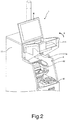
- Fig. 2 is a perspective view illustrating an external appearance of the payment terminal 1 when the cover 111 of the payment terminal 1 is open.
- the cover 111 of the first housing 11 is opened by turning upwards (the direction indicated by the arrow A).
- the paper money handling unit 41 and coin handling unit 42 are contained as being laid one on the other in the first housing 11, and the paper money handling unit 41 is placed under the coin handling unit 42.
- the paper money handling unit 41 performs a paper money receiving process and a paper money dispensing process.
- the paper money handling unit 41 determines whether the received paper money is genuine money.
- the paper money handling unit 41 stores paper money that is determined as genuine money among the received paper money.
- the paper money handling unit 41 dispenses paper money as change calculated based on the received money.
- the coin handling unit 42 performs a coin receiving process and a coin dispensing process.
- the coin handling unit 42 determines whether received coins are genuine money.
- the coin handling unit 42 stores the coin that is determined as genuine money among the received coins.
- the coin handling unit 42 dispenses coins as change calculated based on the received coins.
- the paper money handling unit 41 and the coin handling unit 42 transmit information of an amount of the stored money to the controller 7.
- An amount of money to be dispensed as change is calculated by the controller 7 based on the received money.
- the paper money handling unit 41 and the coin handling unit 42 receives, from the controller 7, information of the amount of money to be dispensed as change.
- the controller 7 integrally controls each unit in the payment terminal 1, which are, for example, the money receiving/dispensing unit 4, the reading unit 5, and the operation unit 6.
- the controller 7 acquires a product code from the scanner 50 of the reading unit 5.
- controller 7 outputs information to be displayed on the monitor 61 of the operation unit 6.
- the controller 7 acquires information of the operator's operation from the touch panel 62 of the operation unit 6.
- controller 7 recognizes the money received by the paper money handling unit 41 and coin handling unit 42 of the money receiving/dispensing unit 4 and instructs the paper money handling unit 41 and the coin handling unit 42 to dispense money.
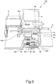
- Fig. 3 is a perspective view of the external appearance, seen from the above, of the self checkout apparatus 100.
- the money receiving/dispensing unit 4 of the first housing 11 has a coin insertion opening 421.
- the coin insertion opening 421 is an opening to which a coin to be put to the coin handling unit 42 is inserted.
- the coin insertion opening 421 is provided at an end on an upper surface of the first housing 11.
- the coin insertion opening 421 can collectively accept a plurality of coins.
- the money receiving/dispensing unit 4 of the first housing 11 has a coin dispense tray 422, a rejection tray 423, a paper money insertion opening 411, and a paper money dispense opening 412.
- the coin dispense tray 422 and the rejection tray 423, and the paper money insertion opening 411 and the paper money dispense opening 412 are provided in a step-like manner in order from the back side where the coin insertion opening 421 is placed toward the front side.
- the surface where the coin insertion opening 421 is provided is an upper face.
- the surface where the coin dispense tray 422 and the rejection tray 423 are provided is a middle face.
- the surface where the paper money insertion opening 411 and the paper money dispense opening 412 are provided is a lower face.
- the customer can take a view of all the insertion openings and dispense openings (dispense trays) from the back side to the front side.
- the coin dispense tray 422 is a receiving tray to receive coins as change dispensed from the coin handling unit 42.
- the rejection tray 423 is a receiving tray to receive a coin which is determined as non-genuine money by the coin handling unit 42 (rejected coins).
- the coin handling unit 42 determines deformed coins, foreign coins, counterfeit coins, and the like as non-genuine money. In other words, the coin handling unit 42 determines those deformed coins, foreign coins, counterfeit coins, and the like as coins which should not be stored.
- a location relation between the coin insertion opening 421, the coin dispense tray 422, and the rejection tray 423 depends on the structure of the coin handling unit 42.
- the coin dispense tray 422 is provided at an end of the payment terminal 1, in a width direction, where is opposite from the other end where the coin insertion opening 421 is provided.
- the coin insertion opening 421 and the coin dispense tray 422 are provided at shifted arrange positions in the height direction, width direction, and depth direction respectively.
- the above arranged positions can improve a visibility and an operability of the coin dispense tray 422.
- the rejection tray 423 is provided next to the coin dispense tray 422, below the coin insertion opening 421.
- the paper money insertion opening 411 is an insertion opening to which paper money to be put in the paper money handling unit 41 is put (inserted).
- the paper money dispense opening 412 is a dispense opening where paper money as change is dispensed from the paper money handling unit 41.
- the location relation of the paper money insertion opening 411 and the paper money dispense opening 412 depends on the structure of the paper money handling unit 41.
- the guide lights 43 to 46 are light emitting diodes (LED), for example.
- the guide lights 43 to 46 are referred to as LEDs 43 to 46.
- the LEDs 43 to 46 inform operation procedures and errors.
- the locations where the LEDs 43 to 46 are provided are not particularly limited as long as provided in vicinity of each unit.
- the number of the LEDs 43 to 46 and the arrangement thereof are not particularly limited.
- the controller 7 When informing an operation procedure, the controller 7 turns on the respective LEDs 43 to 46 at timings when each of the coin insertion opening 421, the coin dispense tray 422, the rejection tray 423, the paper money insertion opening 411, and the paper money dispense opening 412 is used.
- the controller 7 controls to turn on the respective LEDs 43 to 46 so that the LEDs 43 to 46 turned on one after the other according to a progress of the operator's operation procedure.
- the controller 7 turns on the LEDs 43 to 46 near a unit which is in an error (the coin insertion opening 421, the coin dispense tray 422, the rejection tray 423, the paper money insertion opening 411, or the paper money dispense opening 412).
- the payment terminal 1 has a sensor 73 that detects an object (such as a coin) on the coin dispense tray 422 (see Fig. 5 ).
- the senor 73 an optical sensor, a magnetic sensor, an image sensor, or the like is used.
- the optical sensor is provided so that an optical axis of the optical sensor runs across on a bottom of the coin dispense tray 422.
- the optical sensor determines that there is an object on the coin dispense tray 422 when the optical axis is blocked.
- the magnetic sensor is, for example, placed at a position on a rear side of the bottom face of the coin dispense tray 422.
- the magnetic sensor determines that there is an object on the coin dispense tray 422 when a metal is detected.
- the image sensor is placed, for example, above the coin dispense tray 422.
- the image sensor determines that there is an object on the coin dispense tray 422 by an image recognition.
- the paper money insertion opening 411 and the coin insertion opening 421 are examples of openings that take money to be received by the first housing 11.
- the paper money dispense opening 412, the coin dispense tray 422, and the rejection tray 423 are examples of supports for supporting money dispensed from the first housing 11 outside the first housing 11.
- the cover 111 of the first housing 11 has a money placement area 424.
- the money placement area 424 is provided next to the coin insertion opening 421 in a width direction of the payment terminal 1.
- the money placement area 424 is generally referred to as a checking area or a coin checking area.
- the money placement area 424 is used by the customer to visually check money to be used for the payment by putting thereon the money taken from a wallet, for example.
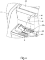
- Fig. 4 is a perspective view illustrating an external appearance of vicinity of the coin dispense tray 422 of the payment terminal 1.
- the illuminating unit 80 illuminates the coin dispense tray 422 by emitting light to the coin dispense tray 422.
- the illuminating unit 80 has a light emitting source 81 and a slit 82.
- the light emitting source 81 emits light to illuminate the coin dispense tray 422.
- the light emitting source 81 is an LED.
- the light emitting source 81 is referred to as an LED 81.
- the LED 81 emits blue light, for example.
- the LED 81 is provided inside the first housing 11.
- the slit 82 is a hole formed in the cover 111 and lets a part of the light emitted by the LED 81 pass therethrough.
- the illuminating unit 80 illuminates the light from the LED 81 onto the coin dispense tray 422 via the slit 82.
- the slit 82 controls an area where is illuminated by the light emitted from the LED 81.
- the LED 81 and slit 82 are provided so that the light that is emitted from the LED 81 and passes though the slit 82 illuminates a predetermined area on the coin dispense tray 422.
- the illuminating unit 80 illuminates the predetermined area as if focusing a spotlight.
- the illuminating unit 80 illuminates the predetermined area from the rear side toward the front side and from the above towards the lower side, not from the right above.
- the LED 81 and the slit 82 are arranged at predetermined positions.
- the predetermined positions are positions that the light emitted from the LED 81 and reflected on a surface of a coin on the coin dispense tray 422 and the coin dispense tray 422 enters eyes of the operator (for example, an adult woman of an average height) who is using the self checkout apparatus 100.
- This arrangement causes a condition that many customers feel brightness from the coin dispense tray 422 and the change.
- Fig. 5 is a block diagram illustrating the hardware configuration of the self checkout apparatus 100.
- the payment terminal 1 incudes the controller 7, an input/output (I/O) device controller 71, and a communication interface (I/F) 72.
- I/O input/output
- I/F communication interface
- the communication I/F 72 communicatably connects the payment terminal 1 to the bagging table 3.
- the I/O device controller 71 connects the controller 7 and the paper money handling unit 41, the coin handling unit 42, the LEDs 43 to 46, 81, the scanner 50, the printer 51, the card reader 52, the monitor 61, the touch panel 62, and the sensor 73.
- the bagging table 3 has an I/O device controller 31, a communication interface (I/F) 32, and a weighing device 33.
- the weighing device 33 weights an item placed on the bagging table 3.
- the communication I/F 32 communicatably connects the bagging table 3 and the payment terminal 1.
- the I/O device controller 31 connects the weighing device 33 to the controller 7 via the communication I/Fs 32 and 72.
- the weighing device 33 weights the item on the bagging table 3 in purpose of fraudulence prevention.
- the controller 7 includes a central processing unit (CPU), a read only memory (ROM), and a random access memory (RAM).
- CPU central processing unit
- ROM read only memory
- RAM random access memory
- the ROM stores various computer programs to be executed by the CPU and various data.
- the RAM temporarily stores the data and computer program when the CPU executes the computer program.
- the controller 7 integrally controls each unit by developing, in the RAM, the computer programs that are read by the CPU from the ROM and executing the program.
- the computer program executed in the self checkout apparatus 100 is stored and provided in a computer-readable recording medium such as a CD-ROM, a flexible disk (FD), a CD-R, a digital versatile disk (DVD) in a file of an installable format or an executable format.
- a computer-readable recording medium such as a CD-ROM, a flexible disk (FD), a CD-R, a digital versatile disk (DVD) in a file of an installable format or an executable format.
- the computer program executed in the self checkout apparatus 100 according to the present embodiment may be stored in a computer connected to a network such as the Internet and provided by being downloaded via the network. Further, the computer program executed in the self checkout apparatus 100 according to the present embodiment may be provided or distributed via the network such as the Internet.
- the computer program executed in the self checkout apparatus 100 may be installed in a ROM or the like in advance and provided.
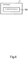
- Fig. 6 is a functional block diagram illustrating a function of the payment process executed by the controller 7 of the payment terminal 1.
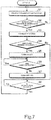
- Fig. 7 is a flowchart illustrating the payment process executed by the payment terminal 1.
- the controller 7 of the payment terminal 1 serves as an illuminating module 701 by following the computer program.
- the illuminating module 701 turns on the LED 81 at timing when a target (which is, the coin dispense tray 422 and the change) is needed to be paid attention.
- the timing when attention is needed is the timing corresponding to the money dispensing process executed by the coin handling unit 42.
- the illuminating module 701 continues the lighting by the LED 81 in a period while the sensor 73 is detecting an object.
- the period is while a coin or the like exists on the coin dispense tray 422, that is, while the coin dispense tray 422 is holding the object, which is assumed as a coin.
- step S1 the controller 7 of the payment terminal 1 executes a product registration process.
- the scanner 50 When the customer holds an image in which a product code is encoded in front of the scanner 50, the scanner 50 reads the encoded image (a bar code or the like) and outputs the product code.
- the encoded image a bar code or the like
- the controller 7 refers to a price look up (PLU) file stored in a storage unit of the payment terminal 1 or an external device connected online.
- the PLU file records product information such as a name, a price, and the like of the product in a format of a table, for example, as associating the information with the product code.
- the controller 7 acquires the product information that is read by the scanner 50 and associated with the product code among the product information recorded in the PLU file. Then, the controller 7 records the product information as purchased product information and adds the price of the product to a purchased amount. In this manner, the product registration process is performed.
- the customer When the customer finishes operating the product registration process and bagging the products, for example, the customer performs an operation on the touch panel 62 to instruct to end the product registration process.
- step S2 the controller 7 of the payment terminal 1 determines whether or not the operation to instruct to end the product registration process is performed on the touch panel 62.
- step S2 When it is determined that the operation to instruct to end the product registration process is performed (step S2, Yes), the process of the controller 7 proceeds to step S3.
- step S3 the controller 7 performs the payment process.
- step S2 No When it is determined that the operation to instruct to end the product registration process is not performed (step S2, No), the process of the controller 7 returns to step S 1.
- the controller 7 of the payment terminal 1 displays a payment amount which is a total of the prices of the products recorded in the monitor 61.
- the controller 7 when receiving an operation to instruct to end the product registration process, displays a payment amount which is a total of the prices of the products recorded in the monitor 61.
- the controller 7 of the payment terminal 1 starts to receive an operation for the payment process by the customer.
- the controller 7 calculates a difference between the received money and the payment amount (change).
- the controller 7 controls the money handling units 41 and 42.
- the controller 7 controls the money handling units 41 and 42 to dispense paper money as change from the paper money dispense opening 412 and coins as change from the coin dispense tray 422.
- step S4 the controller 7 determines whether coins as change are needed.
- step S4 When it is determined that coins as change is needed (step S4, Yes), the process of the controller 7 proceeds to step S5.
- step S5 the controller 7 serves as the illuminating module 701.
- the controller 7 turns on the LED 81.
- step S6 the controller 7 determines whether or not there is an object (coins) on the coin dispense tray 422 by checking the output from the sensor 73.
- step S6 determines that there is an object on the coin dispense tray 422 (step S6, Yes).
- the controller 7 continues a lighting condition of the LED 81.
- step S6 when it is not detected that there is an object on the coin dispense tray 422 (step S6, No), the process of the controller 7 proceeds to step S7.
- step S7 the controller 7 turns off the LED 81.
- step S8 After turning off the LED 81 in step S7 and when it is determined that the coins as change are not needed (step S4, No), the process of the controller 7 proceeds to step S8.
- step S8 the controller 7 determines whether or not the transaction is ended.
- the controller 7 determines that one transaction is ended based on the completion of the payment process.
- step S8, No the controller 7 waits until the transaction is ended.
- step S8 When it is determined that the transaction is ended (step S8, Yes), the process of the controller 7 returns to step S1. The controller 7 waits until a next transaction starts.
- the money handling apparatus (payment terminal 1) according to the present embodiment turns on the LED 81 and illuminates the coin dispense tray 422 according to a timing process of dispensing money to the coin dispense tray 422 of the coin handling unit 42.
- the illumination by the LED 81 can directly illuminate a target compared to one that illuminates in vicinity of the target such as a guide light (LEDs 43 to 46), it can more sufficiently prevent the change from being left without taken.
- the coin dispense tray 422 and the vicinity thereof are composed of a black material, since the coins illuminated by blue light looks sharp and clear, it is further effective to prevent the change from being left without taken.
- the color of the light emitted by the LED 81 does not have to be blue and may be other colors such as yellow, for example.
- the illumination of the light of blue or yellow for guiding is less likely to make people feel uncomfortable, a situation that the change is unseen can be prevented while suppressing the increase of uncomfortableness due to the additionally provided light for guiding.
- the LED 81 may blink, not being simply turned on.
- the illuminating unit 80 that illuminates the coin dispense tray 422 is described as an example; however, the embodiment is not limited by this example.
- the money handling apparatus may have an illumination unit that illuminates the openings (the paper money insertion opening 411 and coin insertion opening 421) and may have an illuminating unit that illuminates another support body (the paper money dispense opening 412). Further, in that case, the timing of turning on the illuminating unit may be synchronized with the timing to turn on the LEDs 43 to 46 serving as guide lights.
- the LED 81 is used as an example of the light emitting source of the illuminating unit 80; however the light emitting source of the illuminating unit 80 is not limited to this example and other light emitting sources may be used.
- the illumination area of the illuminating unit 80 may be restricted by using a light emitting source that emits light having a high directivity, without restricting the illumination area with the slit 82.
- the illumination by the illuminating unit 80 is not limited to the direct illumination from the light emitting source. That is, the illuminating unit 80 may indirectly illuminate the predetermined area by using a condenser lens, a reflector, or the like.
- the illuminating unit 80 is placed at a position so that the light, which is emitted by the light emitting source (LED 81) and reflected on the coin dispense tray 422 or a surface of the coins on the coin dispense tray 422, enters eyes of the operator (for example, an adult woman of an average height) who is using the self checkout apparatus 100.
- the entering angle of the regular reflection light with respect to the eyes of the operator does not satisfy the above described placement condition, the problem may be solved by using a light emitting source that emits a sufficient amount of light.
- the money handling apparatus according to the present embodiment is applied to the payment terminal 1 of the self checkout apparatus 100 for the product registration process and payment process operated by the customer him/herself; however, the present embodiment is not limited to this example.
- the money handling apparatus according to the present embodiment may be placed at a semi-self checkout lane and be applied to an accounting machine with which a customer performs the payment process after a sales assistant performs the product registration process.
- the money handling apparatus may be applied to a ticket vending machine (a ticketing device) that issues food tickets of an eating place or the like.
- the money handling apparatus may be applied to an exit fare machine and a vending machine of a parking facility or a station.
Landscapes
- Physics & Mathematics (AREA)
- General Physics & Mathematics (AREA)
- Engineering & Computer Science (AREA)
- General Engineering & Computer Science (AREA)
- Cash Registers Or Receiving Machines (AREA)
Abstract
Description
- The present invention relates to self-checkout technologies in general and, in particular, embodiments described herein relate to a money handling apparatus, a corresponding system and a method for handling money including a money receiving process and a money dispensing process, usable e.g. in a supermarket.
- These days, in a place such as a supermarket, there are self checkout apparatuses operated by a customer without a sales assistant for a payment process. Those self checkout apparatuses are called a self checkout device or a Self Point Of Sales (POS), for example.
- With the self checkout apparatus, the customer inserts and receives money by himself. Thus, regarding such self checkout apparatus, it is important that an insertion opening and a dispensing opening are made easily recognizable.
- Conventionally, a blinking guide light or the like is provided near those insertion opening and dispensing opening. However, even with lit guide lights, sometimes the customer takes time to find the insertion opening and the dispensing opening adjacent to the lights.
- This is particularly significant when the customer is nervous because it is the first time to use of the self checkout apparatus. Further, such a situation can be seen with a device that a customer inserts or dispenses money by himself, which is a money handling apparatus, in addition to the above self checkout apparatus.
- To solve such problems, there is provided a money handling apparatus that performs a money receiving process and a money dispensing process, comprising:
- a housing;
- a support configured to support money dispensed from an inside of the housing outside the housing;
- an illuminating unit configured to have a light emitting source that emits light and illuminate the support by illuminating the light emitted from the light emitting source onto the support; and
- a controller configured to turn on the light emitting source of the illuminating unit according to a timing in the money dispensing process.
- Preferably, the controller turns on the light emitting source when money is dispensed onto the support from the inside of the housing.
- Preferably still, the money handling apparatus further comprises
a sensor configured to detect whether or not there is money held by the support,
wherein the controller turns on the light emitting source when the sensor detects that there is money being held by the support. - Preferably yet, the controller turns off the light emitting source when the sensor detects that there is no money being held by the support.
- Suitably, the controller
- determines whether the money dispensing process is needed based on money received in the money receiving process, and
- turns on the light emitting source when it is determined that the money dispensing process is needed.
- Suitably still, the controller continues to turn on the light emitting source while money is being held by the support.
- Suitably yet, the light emitting source of the illuminating unit emits blue light or yellow light.
- Suitably further, the illuminating unit has a slit to restrict an area to be illuminated by the light from the light emitting source.
- Typically, the light emitting source is provided in the housing, and
the illuminating unit illuminates the support with the light from the light emitting source through the slit. - Typically still, the light emitting source and the slit are provided at predetermined positions, and
the predetermined positions are positions realizing that the light, which is emitted from the light emitting source and right reflected by the money held by the support, enters eyes of an operator. - Typically yet, the money handling apparatus further includes
an insertion opening provided to the housing to have money received into the housing;
a dispense opening provided to the housing to have money dispensed outside the housing; and
a plurality of guide lights provided in each vicinity of the insertion opening and the dispense opening,
wherein
the controller controls to turn on the plurality of guide lights so that the guide lights to be turned on are switched according to a progress of an operator's operation procedure. - The invention also relates to a method for handling money by performing a money receiving process and a money dispensing process, comprising the steps of:
- providing a housing;
- supporting, by a support, money dispensed from an inside of the housing outside the housing;
- having, by an illuminating unit, a light emitting source that emits light and illuminate the support by illuminating the light emitted from the light emitting source onto the support; and
- turning on, by a controller, the light emitting source of the illuminating unit according to a timing in the money dispensing process.
- Preferably, the turning-on step comprises turning on the light emitting source when money is dispensed onto the support from the inside of the housing.
- Preferably still, the method further comprises the step of:
- detecting, by a sensor, whether or not there is money held by the support,
- The invention further concerns a money handling system in which a money receiving process and a money dispensing process are performed, comprising:
- a housing means;
- a support means configured to support money dispensed from an inside of the housing means outside the housing;
- an illuminating means configured to have a light emitting source that emits light and illuminate the support means by illuminating the light emitted from the light emitting source onto the support means; and
- a controller means configured to turn on the light emitting source of the illuminating means according to a timing in the money dispensing process.
- The above and other objects, features and advantages of the present invention will be made apparent from the following description of the preferred embodiments, given as non-limiting examples, with reference to the accompanying drawings, in which:
-
Fig. 1 is a front view illustrating an external appearance of a self checkout apparatus according to an embodiment. -
Fig. 2 is a perspective view illustrating an external appearance of a payment terminal according to the embodiment in a condition that a cover of the payment terminal is open. -
Fig. 3 is a perspective view of the external appearance, seen from the above, of the self checkout apparatus according to the embodiment. -
Fig. 4 is a perspective view illustrating an external appearance in vicinity of a coin dispense tray of the payment terminal according to the embodiment. -
Fig. 5 is a block diagram illustrating a hardware configuration of the self checkout apparatus according to the embodiment. -
Fig. 6 is a functional block diagram illustrating a function executed by a controller of the payment terminal according to the embodiment. -
Fig. 7 is a flowchart illustrating a payment process executed by the controller of the payment terminal according to the embodiment. - According to an embodiment, a money handling apparatus performs a money receiving process and a money dispensing process.
- The money handling apparatus includes a housing, a support, an illuminating unit, and a controller.
- The support supports money dispensed from an inside of the housing outside the housing.
- The illuminating unit has a light emitting source that emits light.
- The illuminating unit illuminates the support by illuminating the light emitted from the light emitting source onto the support.
- The controller turns on the light emitting source of the illuminating unit according to a timing in the money dispensing process.
- Hereinafter, an embodiment will be described in detail with reference to the drawings.
- In the drawings, the same reference numerals represent same or similar parts.
- As a money handling apparatus according to the present embodiment, a payment terminal (payment device) included in a self checkout apparatus (a self checkout device or a self POS) will be described.
-
Fig. 1 is a front view illustrating an external appearance of aself checkout apparatus 100 according to the embodiment. - As illustrated in
Fig. 1 , theself checkout apparatus 100 includes a payment terminal (payment device) 1, a basket placement table 2, and a bagging table 3. - The
payment terminal 1 performs a money receiving process, a money dispensing process or the like for a later described payment process. - Here, money includes paper money and coins.
- The
payment terminal 1 incudes a money receiving/dispensingunit 4 to perform the money receiving and dispensing processes. Further, thepayment terminal 1 includes areading unit 5, anoperation unit 6, and a controller 7 (seeFig. 5 ), which controls each unit. - Further, the
payment terminal 1 includes afirst housing 11 and asecond housing 12. - The
first housing 11 includes acover 111, which can be kept open or closed. - The
cover 111 rotates upward and downward about ahinge 111a. - The
first housing 11 contains the money receiving/dispensingunit 4. - The money receiving/dispensing
unit 4 includes a paper money handling unit (paper money handling apparatus) 41 and a coin handling unit (coin handling apparatus) 42 (seeFig. 2 ). - Further, the
first housing 11 contains thereading unit 5. - The
second housing 12 contains thecontroller 7. - The
reading unit 5 includes ascanner 50. - The
scanner 50 reads, from a product, identification information to identify the product. - The identification information is, for example, a product code.
- To the product, an image of an encoded product code, which is a bar code or a sign, is attached.
- Further, the
reading unit 5 includes aprinter 51. - The
printer 51 issues a receipt by printing information related to a product sales data process executed by thecontroller 7 on a piece of receipt paper. - The
printer 51 has areceipt support 51a. - The
receipt support 51a supports an issued receipt. Thereceipt support 51a is projected from thefirst housing 11. - In other words, the
receipt support 51a is a convex-shaped support provided projecting from thefirst housing 11. - Further, the
reading unit 5 includes acard reader 52. - The
card reader 52 reads, from a credit card, information related to the payment process executed by thecontroller 7. - The
operation unit 6 includes amonitor 61 and atouch panel 62. - The
monitor 61 displays an image according to a control by thecontroller 7. Thetouch panel 62 is provided on a surface of themonitor 61. Thetouch panel 62 outputs, to thecontroller 7, information based on a position where an operator (a customer, for example) has touched. In other words, thetouch panel 62 outputs, to thecontroller 7, information based on the customer's operation. - The basket placement table 2 is a placement table to place a basket when a customer takes out a product from the basket and holds the product in front of the
scanner 50. - The basket placement table 2 is provided in one side (in the right side in
Fig. 1 ) of thepayment terminal 1. - The bagging table 3 is a placement table used when the customer puts the product in a bag after scanning the product with the
scanner 50. - The bagging table 3 is provided in the other side (in the different side from the basket placement table 2) of the
payment terminal 1. -
Fig. 2 is a perspective view illustrating an external appearance of thepayment terminal 1 when thecover 111 of thepayment terminal 1 is open. - As illustrated in
Fig. 2 , thecover 111 of thefirst housing 11 is opened by turning upwards (the direction indicated by the arrow A). - When the
cover 111 is open, the papermoney handling unit 41 andcoin handling unit 42 in thefirst housing 11 are exposed. - The paper
money handling unit 41 andcoin handling unit 42 are contained as being laid one on the other in thefirst housing 11, and the papermoney handling unit 41 is placed under thecoin handling unit 42. - The paper
money handling unit 41 performs a paper money receiving process and a paper money dispensing process. - More specifically, in the money receiving process, the paper
money handling unit 41 determines whether the received paper money is genuine money. - Further, the paper
money handling unit 41 stores paper money that is determined as genuine money among the received paper money. - Further, in the money dispensing process, the paper
money handling unit 41 dispenses paper money as change calculated based on the received money. - The
coin handling unit 42 performs a coin receiving process and a coin dispensing process. - More specifically, in the receiving process, the
coin handling unit 42 determines whether received coins are genuine money. - Further, the
coin handling unit 42 stores the coin that is determined as genuine money among the received coins. - Further, in the dispensing process, the
coin handling unit 42 dispenses coins as change calculated based on the received coins. - The paper
money handling unit 41 and thecoin handling unit 42 transmit information of an amount of the stored money to thecontroller 7. - An amount of money to be dispensed as change is calculated by the
controller 7 based on the received money. - Further, the paper
money handling unit 41 and thecoin handling unit 42 receives, from thecontroller 7, information of the amount of money to be dispensed as change. - The
controller 7 integrally controls each unit in thepayment terminal 1, which are, for example, the money receiving/dispensingunit 4, thereading unit 5, and theoperation unit 6. - The
controller 7 acquires a product code from thescanner 50 of thereading unit 5. - Further, the
controller 7 outputs information to be displayed on themonitor 61 of theoperation unit 6. - The
controller 7 acquires information of the operator's operation from thetouch panel 62 of theoperation unit 6. - Further, the
controller 7 recognizes the money received by the papermoney handling unit 41 andcoin handling unit 42 of the money receiving/dispensingunit 4 and instructs the papermoney handling unit 41 and thecoin handling unit 42 to dispense money. -
Fig. 3 is a perspective view of the external appearance, seen from the above, of theself checkout apparatus 100. - As illustrated in
Fig. 3 , the money receiving/dispensingunit 4 of thefirst housing 11 has acoin insertion opening 421. - The
coin insertion opening 421 is an opening to which a coin to be put to thecoin handling unit 42 is inserted. - The
coin insertion opening 421 is provided at an end on an upper surface of thefirst housing 11. - The
coin insertion opening 421 can collectively accept a plurality of coins. - Further, the money receiving/dispensing
unit 4 of thefirst housing 11 has a coin dispensetray 422, arejection tray 423, a papermoney insertion opening 411, and a paper money dispenseopening 412. - As illustrated in
Fig. 3 , in the money receiving/dispensingunit 4 in thefirst housing 11, the coin dispensetray 422 and therejection tray 423, and the papermoney insertion opening 411 and the paper money dispense opening 412 are provided in a step-like manner in order from the back side where thecoin insertion opening 421 is placed toward the front side. - In other words, the surface where the
coin insertion opening 421 is provided is an upper face. The surface where the coin dispensetray 422 and therejection tray 423 are provided is a middle face. The surface where the papermoney insertion opening 411 and the paper money dispense opening 412 are provided is a lower face. - By providing the respective types of insertion openings and dispense openings (dispense trays) in a step-like manner as described above, the customer can take a view of all the insertion openings and dispense openings (dispense trays) from the back side to the front side.
- The coin dispense
tray 422 is a receiving tray to receive coins as change dispensed from thecoin handling unit 42. - The
rejection tray 423 is a receiving tray to receive a coin which is determined as non-genuine money by the coin handling unit 42 (rejected coins). - The
coin handling unit 42 determines deformed coins, foreign coins, counterfeit coins, and the like as non-genuine money. In other words, thecoin handling unit 42 determines those deformed coins, foreign coins, counterfeit coins, and the like as coins which should not be stored. - A location relation between the
coin insertion opening 421, the coin dispensetray 422, and therejection tray 423 depends on the structure of thecoin handling unit 42. - As illustrated in
Fig. 3 , the coin dispensetray 422 is provided at an end of thepayment terminal 1, in a width direction, where is opposite from the other end where thecoin insertion opening 421 is provided. - In other words, the
coin insertion opening 421 and the coin dispensetray 422 are provided at shifted arrange positions in the height direction, width direction, and depth direction respectively. - The above arranged positions can improve a visibility and an operability of the coin dispense
tray 422. - Here, the
rejection tray 423 is provided next to the coin dispensetray 422, below thecoin insertion opening 421. - The paper
money insertion opening 411 is an insertion opening to which paper money to be put in the papermoney handling unit 41 is put (inserted). - The paper money dispense opening 412 is a dispense opening where paper money as change is dispensed from the paper
money handling unit 41. The location relation of the papermoney insertion opening 411 and the paper money dispense opening 412 depends on the structure of the papermoney handling unit 41. - Further, as illustrated in
Fig. 3 , there areguide lights coin insertion opening 421, the coin dispensetray 422, therejection tray 423, the papermoney insertion opening 411, and the paper money dispense opening 412, respectively. - The guide lights 43 to 46 are light emitting diodes (LED), for example.
- Hereinafter, the guide lights 43 to 46 are referred to as
LEDs 43 to 46. - The
LEDs 43 to 46 inform operation procedures and errors. - Here, the locations where the
LEDs 43 to 46 are provided are not particularly limited as long as provided in vicinity of each unit. - Further, the number of the
LEDs 43 to 46 and the arrangement thereof are not particularly limited. - When informing an operation procedure, the
controller 7 turns on therespective LEDs 43 to 46 at timings when each of thecoin insertion opening 421, the coin dispensetray 422, therejection tray 423, the papermoney insertion opening 411, and the paper money dispense opening 412 is used. - In other words, the
controller 7 controls to turn on therespective LEDs 43 to 46 so that theLEDs 43 to 46 turned on one after the other according to a progress of the operator's operation procedure. - Further, when informing an error, the
controller 7 turns on theLEDs 43 to 46 near a unit which is in an error (thecoin insertion opening 421, the coin dispensetray 422, therejection tray 423, the papermoney insertion opening 411, or the paper money dispense opening 412). - The
payment terminal 1 has asensor 73 that detects an object (such as a coin) on the coin dispense tray 422 (seeFig. 5 ). - As the
sensor 73, an optical sensor, a magnetic sensor, an image sensor, or the like is used. - For example, the optical sensor is provided so that an optical axis of the optical sensor runs across on a bottom of the coin dispense
tray 422. - The optical sensor determines that there is an object on the coin dispense
tray 422 when the optical axis is blocked. - The magnetic sensor is, for example, placed at a position on a rear side of the bottom face of the coin dispense
tray 422. - The magnetic sensor determines that there is an object on the coin dispense
tray 422 when a metal is detected. - The image sensor is placed, for example, above the coin dispense
tray 422. - The image sensor determines that there is an object on the coin dispense
tray 422 by an image recognition. - Here, the paper
money insertion opening 411 and thecoin insertion opening 421 are examples of openings that take money to be received by thefirst housing 11. - Further, the paper money dispense opening 412, the coin dispense
tray 422, and therejection tray 423 are examples of supports for supporting money dispensed from thefirst housing 11 outside thefirst housing 11. - The
cover 111 of thefirst housing 11 has amoney placement area 424. - The
money placement area 424 is provided next to thecoin insertion opening 421 in a width direction of thepayment terminal 1. - The
money placement area 424 is generally referred to as a checking area or a coin checking area. - When an operation of the payment process is performed with the
payment terminal 1, themoney placement area 424 is used by the customer to visually check money to be used for the payment by putting thereon the money taken from a wallet, for example. -
Fig. 4 is a perspective view illustrating an external appearance of vicinity of the coin dispensetray 422 of thepayment terminal 1. - There is an illuminating
unit 80 under themoney placement area 424 and above the coin dispensetray 422. The illuminatingunit 80 illuminates the coin dispensetray 422 by emitting light to the coin dispensetray 422. - The illuminating
unit 80 has alight emitting source 81 and aslit 82. - The
light emitting source 81 emits light to illuminate the coin dispensetray 422. - The
light emitting source 81 is an LED. - Hereinafter, the
light emitting source 81 is referred to as anLED 81. - The
LED 81 emits blue light, for example. - The
LED 81 is provided inside thefirst housing 11. - The
slit 82 is a hole formed in thecover 111 and lets a part of the light emitted by theLED 81 pass therethrough. - In other words, the illuminating
unit 80 illuminates the light from theLED 81 onto the coin dispensetray 422 via theslit 82. Theslit 82 controls an area where is illuminated by the light emitted from theLED 81. - The
LED 81 and slit 82 are provided so that the light that is emitted from theLED 81 and passes though theslit 82 illuminates a predetermined area on the coin dispensetray 422. - With this structure, the illuminating
unit 80 illuminates the predetermined area as if focusing a spotlight. - Further, the illuminating
unit 80 illuminates the predetermined area from the rear side toward the front side and from the above towards the lower side, not from the right above. - More specifically, the
LED 81 and theslit 82 are arranged at predetermined positions. - The predetermined positions are positions that the light emitted from the
LED 81 and reflected on a surface of a coin on the coin dispensetray 422 and the coin dispensetray 422 enters eyes of the operator (for example, an adult woman of an average height) who is using theself checkout apparatus 100. - This arrangement causes a condition that many customers feel brightness from the coin dispense
tray 422 and the change. - Thus, this makes the customers easily focus on the change and it is less likely to forget to take the change.
- Next, a hardware configuration of the
self checkout apparatus 100 will be explained. -
Fig. 5 is a block diagram illustrating the hardware configuration of theself checkout apparatus 100. - As illustrated in
Fig. 5 , thepayment terminal 1 incudes thecontroller 7, an input/output (I/O)device controller 71, and a communication interface (I/F) 72. - The communication I/
F 72 communicatably connects thepayment terminal 1 to the bagging table 3. - The I/
O device controller 71 connects thecontroller 7 and the papermoney handling unit 41, thecoin handling unit 42, theLEDs 43 to 46, 81, thescanner 50, theprinter 51, thecard reader 52, themonitor 61, thetouch panel 62, and thesensor 73. - The bagging table 3 has an I/
O device controller 31, a communication interface (I/F) 32, and a weighing device 33. - The weighing device 33 weights an item placed on the bagging table 3.
- The communication I/
F 32 communicatably connects the bagging table 3 and thepayment terminal 1. In other words, the I/O device controller 31 connects the weighing device 33 to thecontroller 7 via the communication I/Fs - The weighing device 33 weights the item on the bagging table 3 in purpose of fraudulence prevention.
- The
controller 7 includes a central processing unit (CPU), a read only memory (ROM), and a random access memory (RAM). - The ROM stores various computer programs to be executed by the CPU and various data.
- The RAM temporarily stores the data and computer program when the CPU executes the computer program.
- The
controller 7 integrally controls each unit by developing, in the RAM, the computer programs that are read by the CPU from the ROM and executing the program. - Here, the computer program executed in the
self checkout apparatus 100 according to the present embodiment is stored and provided in a computer-readable recording medium such as a CD-ROM, a flexible disk (FD), a CD-R, a digital versatile disk (DVD) in a file of an installable format or an executable format. - Further, the computer program executed in the
self checkout apparatus 100 according to the present embodiment may be stored in a computer connected to a network such as the Internet and provided by being downloaded via the network. Further, the computer program executed in theself checkout apparatus 100 according to the present embodiment may be provided or distributed via the network such as the Internet. - Further, the computer program executed in the
self checkout apparatus 100 according to the present embodiment may be installed in a ROM or the like in advance and provided. - Next, the payment process which is a characteristic function of the present embodiment among the various processes executed by the
controller 7 of thepayment terminal 1 in theself checkout apparatus 100 will be explained. -
Fig. 6 is a functional block diagram illustrating a function of the payment process executed by thecontroller 7 of thepayment terminal 1. -
Fig. 7 is a flowchart illustrating the payment process executed by thepayment terminal 1. - In the payment process, as illustrated in
Fig. 6 , thecontroller 7 of thepayment terminal 1 serves as an illuminatingmodule 701 by following the computer program. - The illuminating
module 701 turns on theLED 81 at timing when a target (which is, the coin dispensetray 422 and the change) is needed to be paid attention. - The timing when attention is needed is the timing corresponding to the money dispensing process executed by the
coin handling unit 42. - Further, the illuminating
module 701 continues the lighting by theLED 81 in a period while thesensor 73 is detecting an object. - Here, the period is while a coin or the like exists on the coin dispense
tray 422, that is, while the coin dispensetray 422 is holding the object, which is assumed as a coin. - The payment process executed by the
controller 7 of thepayment terminal 1 will be explained with reference to the flowchart illustrated inFig. 7 . - As illustrated in
Fig. 7 , firstly in step S1, thecontroller 7 of thepayment terminal 1 executes a product registration process. - Here, the product registration process will be explained.
- When the customer holds an image in which a product code is encoded in front of the
scanner 50, thescanner 50 reads the encoded image (a bar code or the like) and outputs the product code. - When the
scanner 50 outputs the product code, for example, thecontroller 7 refers to a price look up (PLU) file stored in a storage unit of thepayment terminal 1 or an external device connected online. The PLU file records product information such as a name, a price, and the like of the product in a format of a table, for example, as associating the information with the product code. - Next, the
controller 7 acquires the product information that is read by thescanner 50 and associated with the product code among the product information recorded in the PLU file. Then, thecontroller 7 records the product information as purchased product information and adds the price of the product to a purchased amount. In this manner, the product registration process is performed. - When the customer finishes operating the product registration process and bagging the products, for example, the customer performs an operation on the
touch panel 62 to instruct to end the product registration process. - In step S2, the
controller 7 of thepayment terminal 1 determines whether or not the operation to instruct to end the product registration process is performed on thetouch panel 62. - When it is determined that the operation to instruct to end the product registration process is performed (step S2, Yes), the process of the
controller 7 proceeds to step S3. - In step S3, the
controller 7 performs the payment process. - When it is determined that the operation to instruct to end the product registration process is not performed (step S2, No), the process of the
controller 7 returns to stepS 1. - Here, the payment process will be explained.
- When the
touch panel 62 receives an operation by the customer to proceed to a payment process, thecontroller 7 of thepayment terminal 1 displays a payment amount which is a total of the prices of the products recorded in themonitor 61. - In a case of the present embodiment, for example, when receiving an operation to instruct to end the product registration process, the
controller 7 displays a payment amount which is a total of the prices of the products recorded in themonitor 61. - In this manner, the
controller 7 of thepayment terminal 1 starts to receive an operation for the payment process by the customer. - In a case of a cash payment, when money is put to the paper money insertion opening 411 of the paper
money handling unit 41 and thecoin insertion opening 421 of thecoin handling unit 42, thecontroller 7 calculates a difference between the received money and the payment amount (change). - When there is change as a result of the calculation, the
controller 7 controls themoney handling units - The
controller 7 controls themoney handling units tray 422. - After the difference between the inserted money and the payment amount is calculated in the payment process, in step S4, the
controller 7 determines whether coins as change are needed. - When it is determined that coins as change is needed (step S4, Yes), the process of the
controller 7 proceeds to step S5. - In step S5, the
controller 7 serves as the illuminatingmodule 701. - In other words, when the coins as change are dispensed to the coin dispense
tray 422 by thecoin handling unit 42, thecontroller 7 turns on theLED 81. - Next, in step S6, the
controller 7 determines whether or not there is an object (coins) on the coin dispensetray 422 by checking the output from thesensor 73. - While the
sensor 73 is detecting that there is an object on the coin dispensetray 422, thecontroller 7 determines that there is an object on the coin dispense tray 422 (step S6, Yes). - The
controller 7 continues a lighting condition of theLED 81. - Further, when it is not detected that there is an object on the coin dispense tray 422 (step S6, No), the process of the
controller 7 proceeds to step S7. - In step S7, the
controller 7 turns off theLED 81. - After turning off the
LED 81 in step S7 and when it is determined that the coins as change are not needed (step S4, No), the process of thecontroller 7 proceeds to step S8. - In step S8, the
controller 7 determines whether or not the transaction is ended. Thecontroller 7 determines that one transaction is ended based on the completion of the payment process. - When it is determined that the transaction is not ended (step S8, No), the
controller 7 waits until the transaction is ended. - When it is determined that the transaction is ended (step S8, Yes), the process of the
controller 7 returns to step S1. Thecontroller 7 waits until a next transaction starts. - As described above, the money handling apparatus (payment terminal 1) according to the present embodiment turns on the
LED 81 and illuminates the coin dispensetray 422 according to a timing process of dispensing money to the coin dispensetray 422 of thecoin handling unit 42. - Thus, according to the present embodiment, attention of the customer as an operator can be directed to a proper part, that is, the coin dispense tray 422 (the change) at a proper timing.
- Since the illumination by the
LED 81 can directly illuminate a target compared to one that illuminates in vicinity of the target such as a guide light (LEDs 43 to 46), it can more sufficiently prevent the change from being left without taken. - Here, in a case that the coin dispense
tray 422 and the vicinity thereof are composed of a black material, since the coins illuminated by blue light looks sharp and clear, it is further effective to prevent the change from being left without taken. - Further, the color of the light emitted by the
LED 81 does not have to be blue and may be other colors such as yellow, for example. The illumination of the light of blue or yellow for guiding is less likely to make people feel uncomfortable, a situation that the change is unseen can be prevented while suppressing the increase of uncomfortableness due to the additionally provided light for guiding. - To further enhance this effect, the
LED 81 may blink, not being simply turned on. - Further, according to the present embodiment, the illuminating
unit 80 that illuminates the coin dispensetray 422 is described as an example; however, the embodiment is not limited by this example. - In other words, the money handling apparatus may have an illumination unit that illuminates the openings (the paper
money insertion opening 411 and coin insertion opening 421) and may have an illuminating unit that illuminates another support body (the paper money dispense opening 412). Further, in that case, the timing of turning on the illuminating unit may be synchronized with the timing to turn on theLEDs 43 to 46 serving as guide lights. - Further, according to the present embodiment, the
LED 81 is used as an example of the light emitting source of the illuminatingunit 80; however the light emitting source of the illuminatingunit 80 is not limited to this example and other light emitting sources may be used. - Further, the illumination area of the illuminating
unit 80 may be restricted by using a light emitting source that emits light having a high directivity, without restricting the illumination area with theslit 82. - Further, the illumination by the illuminating
unit 80 is not limited to the direct illumination from the light emitting source. That is, the illuminatingunit 80 may indirectly illuminate the predetermined area by using a condenser lens, a reflector, or the like. - Further, the illuminating
unit 80 is placed at a position so that the light, which is emitted by the light emitting source (LED 81) and reflected on the coin dispensetray 422 or a surface of the coins on the coin dispensetray 422, enters eyes of the operator (for example, an adult woman of an average height) who is using theself checkout apparatus 100. Here, when the entering angle of the regular reflection light with respect to the eyes of the operator does not satisfy the above described placement condition, the problem may be solved by using a light emitting source that emits a sufficient amount of light. - Here, an example in which the money handling apparatus according to the present embodiment is applied to the
payment terminal 1 of theself checkout apparatus 100 for the product registration process and payment process operated by the customer him/herself has been explained; however, the present embodiment is not limited to this example. For example, the money handling apparatus according to the present embodiment may be placed at a semi-self checkout lane and be applied to an accounting machine with which a customer performs the payment process after a sales assistant performs the product registration process. - Further, the money handling apparatus according to the present embodiment may be applied to a ticket vending machine (a ticketing device) that issues food tickets of an eating place or the like.
- Further, the money handling apparatus according to the present embodiment may be applied to an exit fare machine and a vending machine of a parking facility or a station.
- While certain embodiments have been described, these embodiments have been presented by way of example only, and are not intended to limit the scope of the inventions. Indeed, the novel embodiments described herein may be embodied in a variety of other forms; furthermore, various omissions, substitutions and changes in the form of the embodiments described herein may be made without departing from the framework of the inventions. The accompanying claims and their equivalents are intended to cover such forms or modifications as would fall within the scope and framework of the inventions.
Claims (15)
- A money handling apparatus that performs a money receiving process and a money dispensing process, comprising:a housing;a support configured to support money dispensed from an inside of the housing outside the housing;an illuminating unit configured to have a light emitting source that emits light and illuminate the support by illuminating the light emitted from the light emitting source onto the support; anda controller configured to turn on the light emitting source of the illuminating unit according to a timing in the money dispensing process.
- The money handling apparatus according to claim 1, wherein the controller turns on the light emitting source when money is dispensed onto the support from the inside of the housing.
- The money handling apparatus according to claim 1 or 2, further comprising
a sensor configured to detect whether or not there is money held by the support,
wherein the controller turns on the light emitting source when the sensor detects that there is money being held by the support. - The money handling apparatus according to any one of claims 1 to 3, wherein the controller turns off the light emitting source when the sensor detects that there is no money being held by the support.
- The money handling apparatus according to any one of claims 1 to 4, wherein
the controller
determines whether the money dispensing process is needed based on money received in the money receiving process, and
turns on the light emitting source when it is determined that the money dispensing process is needed. - The money handling apparatus according to any one of claims 1 to 5, wherein the controller continues to turn on the light emitting source while money is being held by the support.
- The money handling apparatus according to any one of claims 1 to 6, wherein the light emitting source of the illuminating unit emits blue light or yellow light.
- The money handling apparatus according to any one of claims 1 to 7, wherein the illuminating unit has a slit to restrict an area to be illuminated by the light from the light emitting source.
- The money handling apparatus according to any one of claims 1 to 8, wherein
the light emitting source is provided in the housing, and
the illuminating unit illuminates the support with the light from the light emitting source through the slit. - The money handling apparatus according to claim 8 or 9, wherein
the light emitting source and the slit are provided at predetermined positions, and
the predetermined positions are positions realizing that the light, which is emitted from the light emitting source and right reflected by the money held by the support, enters eyes of an operator. - The money handling apparatus according to any one of claims 1 to 10, further including
an insertion opening provided to the housing to have money received into the housing;
a dispense opening provided to the housing to have money dispensed outside the housing; and
a plurality of guide lights provided in each vicinity of the insertion opening and the dispense opening,
wherein
the controller controls to turn on the plurality of guide lights so that the guide lights to be turned on are switched according to a progress of an operator's operation procedure. - A method for handling money by performing a money receiving process and a money dispensing process, comprising the steps of:- providing a housing;- supporting, by a support, money dispensed from an inside of the housing outside the housing;- having, by an illuminating unit, a light emitting source that emits light and illuminate the support by illuminating the light emitted from the light emitting source onto the support; and- turning on, by a controller, the light emitting source of the illuminating unit according to a timing in the money dispensing process.
- The method according to claim 12, wherein the turning-on step comprises turning on the light emitting source when money is dispensed onto the support from the inside of the housing.
- The method according to claim12 or 13, further comprising the step of:- detecting, by a sensor, whether or not there is money held by the support, wherein the controller turns on the light emitting source when the sensor detects that there is money being held by the support.
- A money handling system in which a money receiving process and a money dispensing process are performed, comprising:a housing means;a support means configured to support money dispensed from an inside of the housing means outside the housing;an illuminating means configured to have a light emitting source that emits light and illuminate the support means by illuminating the light emitted from the light emitting source onto the support means; anda controller means configured to turn on the light emitting source of the illuminating means according to a timing in the money dispensing process.
Applications Claiming Priority (1)
| Application Number | Priority Date | Filing Date | Title |
|---|---|---|---|
| JP2016020780A JP2017138890A (en) | 2016-02-05 | 2016-02-05 | Tellers machine |
Publications (1)
| Publication Number | Publication Date |
|---|---|
| EP3203450A1 true EP3203450A1 (en) | 2017-08-09 |
Family
ID=57965765
Family Applications (1)
| Application Number | Title | Priority Date | Filing Date |
|---|---|---|---|
| EP17154507.2A Withdrawn EP3203450A1 (en) | 2016-02-05 | 2017-02-03 | Money handling apparatus |
Country Status (3)
| Country | Link |
|---|---|
| US (1) | US20170231054A1 (en) |
| EP (1) | EP3203450A1 (en) |
| JP (1) | JP2017138890A (en) |
Families Citing this family (5)
| Publication number | Priority date | Publication date | Assignee | Title |
|---|---|---|---|---|
| JP2019211910A (en) * | 2018-06-01 | 2019-12-12 | 株式会社寺岡精工 | Commodity sales data processing device and program |
| CN113838252B (en) * | 2020-06-23 | 2023-09-12 | 东芝泰格有限公司 | Checkout equipment and checkout device |
| USD1108532S1 (en) * | 2024-01-05 | 2026-01-06 | Toshiba Global Commerce Solutions, Inc. | Self-checkout station |
| USD1106094S1 (en) * | 2024-12-10 | 2025-12-16 | Toshiba Global Commerce Solutions, Inc. | Kiosk |
| USD1112221S1 (en) * | 2024-12-10 | 2026-02-10 | Toshiba Global Commerce Solutions, Inc. | Kiosk |
Citations (4)
| Publication number | Priority date | Publication date | Assignee | Title |
|---|---|---|---|---|
| US20040149819A1 (en) * | 2002-11-25 | 2004-08-05 | Diebold Self-Service Systems Division Of Diebold, Incorporated | Cash dispensing automated banking machine diagnostic method |
| US20090057423A1 (en) * | 2007-09-03 | 2009-03-05 | Glory Ltd. | Cash processing machine |
| US20110057036A1 (en) * | 2009-09-04 | 2011-03-10 | Toshiba Tec Kabushiki Kaisha | Receiving and dispensing unit and self-checkout system |
| EP2950280A1 (en) * | 2014-05-30 | 2015-12-02 | Hitachi-Omron Terminal Solutions, Corp. | Bill handling apparatus |
Family Cites Families (10)
| Publication number | Priority date | Publication date | Assignee | Title |
|---|---|---|---|---|
| FR2172649A5 (en) * | 1972-02-16 | 1973-09-28 | Nat Res Dev | |
| JPS63149786A (en) * | 1986-12-15 | 1988-06-22 | 株式会社日立製作所 | Automatic coin handling device |
| JPH06223256A (en) * | 1993-01-21 | 1994-08-12 | Laurel Bank Mach Co Ltd | Residual coin detection device in circulating coin depositing and dispensing machine |
| JP3532404B2 (en) * | 1997-12-18 | 2004-05-31 | アルゼ株式会社 | Gaming machine |
| JP2002312833A (en) * | 2001-04-11 | 2002-10-25 | Glory Ltd | Money deposit and withdrawal processing system |
| JP2005142032A (en) * | 2003-11-06 | 2005-06-02 | Koha Co Ltd | Vending machine lighting device and vending machine |
| KR101075599B1 (en) * | 2004-06-23 | 2011-10-20 | 삼성전자주식회사 | Display device |
| JP2007140586A (en) * | 2005-11-14 | 2007-06-07 | Toyo Network Systems Co Ltd | Cash handling device |
| EP1930858A1 (en) * | 2006-12-07 | 2008-06-11 | Krzysztof Beyger | Cash tray |
| JP4903761B2 (en) * | 2008-09-12 | 2012-03-28 | 沖電気工業株式会社 | Automatic transaction equipment |
-
2016
- 2016-02-05 JP JP2016020780A patent/JP2017138890A/en active Pending
-
2017
- 2017-01-12 US US15/404,633 patent/US20170231054A1/en not_active Abandoned
- 2017-02-03 EP EP17154507.2A patent/EP3203450A1/en not_active Withdrawn
Patent Citations (4)
| Publication number | Priority date | Publication date | Assignee | Title |
|---|---|---|---|---|
| US20040149819A1 (en) * | 2002-11-25 | 2004-08-05 | Diebold Self-Service Systems Division Of Diebold, Incorporated | Cash dispensing automated banking machine diagnostic method |
| US20090057423A1 (en) * | 2007-09-03 | 2009-03-05 | Glory Ltd. | Cash processing machine |
| US20110057036A1 (en) * | 2009-09-04 | 2011-03-10 | Toshiba Tec Kabushiki Kaisha | Receiving and dispensing unit and self-checkout system |
| EP2950280A1 (en) * | 2014-05-30 | 2015-12-02 | Hitachi-Omron Terminal Solutions, Corp. | Bill handling apparatus |
Also Published As
| Publication number | Publication date |
|---|---|
| JP2017138890A (en) | 2017-08-10 |
| US20170231054A1 (en) | 2017-08-10 |
Similar Documents
| Publication | Publication Date | Title |
|---|---|---|
| US20170231054A1 (en) | Money handling apparatus | |
| US8567673B2 (en) | Code reader, sales data processing apparatus and method | |
| US10672235B2 (en) | Settlement apparatus | |
| US11853992B2 (en) | Settlement device | |
| US10311417B2 (en) | Sales data processing apparatus and method for instructing operation on operation section to be operated next | |
| EP3557512A1 (en) | Apparatus and method for registering commodity information | |
| US10950098B2 (en) | Cash processing apparatus | |
| JP2017107428A (en) | Commodity selling data processing device and program | |
| JP7670775B2 (en) | Self-payment device and program | |
| US20250094992A1 (en) | Self-service commodity sales data processing device and method thereof | |
| US20190251540A1 (en) | Self-service checkout apparatus and method thereof | |
| EP3699878B1 (en) | Article information reading apparatus | |
| US20210375085A1 (en) | Money storage device and checkout device | |
| JP2016206738A (en) | Transaction apparatus and operation guide method | |
| JP7171817B2 (en) | money handling device | |
| JP6666398B2 (en) | Payment device | |
| EP4064233A1 (en) | Money processing device | |
| JP6395878B2 (en) | Payment device | |
| CN113838252B (en) | Checkout equipment and checkout device |
Legal Events
| Date | Code | Title | Description |
|---|---|---|---|
| PUAI | Public reference made under article 153(3) epc to a published international application that has entered the european phase |
Free format text: ORIGINAL CODE: 0009012 |
|
| AK | Designated contracting states |
Kind code of ref document: A1 Designated state(s): AL AT BE BG CH CY CZ DE DK EE ES FI FR GB GR HR HU IE IS IT LI LT LU LV MC MK MT NL NO PL PT RO RS SE SI SK SM TR |
|
| AX | Request for extension of the european patent |
Extension state: BA ME |
|
| 17P | Request for examination filed |
Effective date: 20180209 |
|
| RBV | Designated contracting states (corrected) |
Designated state(s): AL AT BE BG CH CY CZ DE DK EE ES FI FR GB GR HR HU IE IS IT LI LT LU LV MC MK MT NL NO PL PT RO RS SE SI SK SM TR |
|
| 17Q | First examination report despatched |
Effective date: 20181203 |
|
| STAA | Information on the status of an ep patent application or granted ep patent |
Free format text: STATUS: THE APPLICATION HAS BEEN WITHDRAWN |
|
| 18W | Application withdrawn |
Effective date: 20190326 |