EP3203372B1 - Medical imaging system - Google Patents
Medical imaging system Download PDFInfo
- Publication number
- EP3203372B1 EP3203372B1 EP17151211.4A EP17151211A EP3203372B1 EP 3203372 B1 EP3203372 B1 EP 3203372B1 EP 17151211 A EP17151211 A EP 17151211A EP 3203372 B1 EP3203372 B1 EP 3203372B1
- Authority
- EP
- European Patent Office
- Prior art keywords
- mobile
- nsc
- wall
- power
- image signal
- Prior art date
- Legal status (The legal status is an assumption and is not a legal conclusion. Google has not performed a legal analysis and makes no representation as to the accuracy of the status listed.)
- Active
Links
Images


Classifications
-
- G—PHYSICS
- G09—EDUCATION; CRYPTOGRAPHY; DISPLAY; ADVERTISING; SEALS
- G09G—ARRANGEMENTS OR CIRCUITS FOR CONTROL OF INDICATING DEVICES USING STATIC MEANS TO PRESENT VARIABLE INFORMATION
- G09G5/00—Control arrangements or circuits for visual indicators common to cathode-ray tube indicators and other visual indicators
- G09G5/003—Details of a display terminal, the details relating to the control arrangement of the display terminal and to the interfaces thereto
- G09G5/005—Adapting incoming signals to the display format of the display terminal
-
- G—PHYSICS
- G06—COMPUTING OR CALCULATING; COUNTING
- G06F—ELECTRIC DIGITAL DATA PROCESSING
- G06F3/00—Input arrangements for transferring data to be processed into a form capable of being handled by the computer; Output arrangements for transferring data from processing unit to output unit, e.g. interface arrangements
- G06F3/14—Digital output to display device ; Cooperation and interconnection of the display device with other functional units
- G06F3/147—Digital output to display device ; Cooperation and interconnection of the display device with other functional units using display panels
-
- G—PHYSICS
- G09—EDUCATION; CRYPTOGRAPHY; DISPLAY; ADVERTISING; SEALS
- G09G—ARRANGEMENTS OR CIRCUITS FOR CONTROL OF INDICATING DEVICES USING STATIC MEANS TO PRESENT VARIABLE INFORMATION
- G09G3/00—Control arrangements or circuits, of interest only in connection with visual indicators other than cathode-ray tubes
- G09G3/20—Control arrangements or circuits, of interest only in connection with visual indicators other than cathode-ray tubes for presentation of an assembly of a number of characters, e.g. a page, by composing the assembly by combination of individual elements arranged in a matrix no fixed position being assigned to or needed to be assigned to the individual characters or partial characters
- G09G3/2092—Details of a display terminals using a flat panel, the details relating to the control arrangement of the display terminal and to the interfaces thereto
- G09G3/2096—Details of the interface to the display terminal specific for a flat panel
-
- G—PHYSICS
- G09—EDUCATION; CRYPTOGRAPHY; DISPLAY; ADVERTISING; SEALS
- G09G—ARRANGEMENTS OR CIRCUITS FOR CONTROL OF INDICATING DEVICES USING STATIC MEANS TO PRESENT VARIABLE INFORMATION
- G09G5/00—Control arrangements or circuits for visual indicators common to cathode-ray tube indicators and other visual indicators
- G09G5/003—Details of a display terminal, the details relating to the control arrangement of the display terminal and to the interfaces thereto
- G09G5/006—Details of the interface to the display terminal
-
- G—PHYSICS
- G09—EDUCATION; CRYPTOGRAPHY; DISPLAY; ADVERTISING; SEALS
- G09G—ARRANGEMENTS OR CIRCUITS FOR CONTROL OF INDICATING DEVICES USING STATIC MEANS TO PRESENT VARIABLE INFORMATION
- G09G5/00—Control arrangements or circuits for visual indicators common to cathode-ray tube indicators and other visual indicators
- G09G5/003—Details of a display terminal, the details relating to the control arrangement of the display terminal and to the interfaces thereto
- G09G5/006—Details of the interface to the display terminal
- G09G5/008—Clock recovery
-
- G—PHYSICS
- G09—EDUCATION; CRYPTOGRAPHY; DISPLAY; ADVERTISING; SEALS
- G09G—ARRANGEMENTS OR CIRCUITS FOR CONTROL OF INDICATING DEVICES USING STATIC MEANS TO PRESENT VARIABLE INFORMATION
- G09G5/00—Control arrangements or circuits for visual indicators common to cathode-ray tube indicators and other visual indicators
- G09G5/36—Control arrangements or circuits for visual indicators common to cathode-ray tube indicators and other visual indicators characterised by the display of a graphic pattern, e.g. using an all-points-addressable [APA] memory
- G09G5/363—Graphics controllers
-
- H—ELECTRICITY
- H04—ELECTRIC COMMUNICATION TECHNIQUE
- H04N—PICTORIAL COMMUNICATION, e.g. TELEVISION
- H04N11/00—Colour television systems
- H04N11/06—Transmission systems characterised by the manner in which the individual colour picture signal components are combined
- H04N11/20—Conversion of the manner in which the individual colour picture signal components are combined, e.g. conversion of colour television standards
-
- G—PHYSICS
- G09—EDUCATION; CRYPTOGRAPHY; DISPLAY; ADVERTISING; SEALS
- G09G—ARRANGEMENTS OR CIRCUITS FOR CONTROL OF INDICATING DEVICES USING STATIC MEANS TO PRESENT VARIABLE INFORMATION
- G09G2370/00—Aspects of data communication
- G09G2370/02—Networking aspects
- G09G2370/025—LAN communication management
-
- G—PHYSICS
- G09—EDUCATION; CRYPTOGRAPHY; DISPLAY; ADVERTISING; SEALS
- G09G—ARRANGEMENTS OR CIRCUITS FOR CONTROL OF INDICATING DEVICES USING STATIC MEANS TO PRESENT VARIABLE INFORMATION
- G09G2370/00—Aspects of data communication
- G09G2370/04—Exchange of auxiliary data, i.e. other than image data, between monitor and graphics controller
- G09G2370/042—Exchange of auxiliary data, i.e. other than image data, between monitor and graphics controller for monitor identification
-
- G—PHYSICS
- G09—EDUCATION; CRYPTOGRAPHY; DISPLAY; ADVERTISING; SEALS
- G09G—ARRANGEMENTS OR CIRCUITS FOR CONTROL OF INDICATING DEVICES USING STATIC MEANS TO PRESENT VARIABLE INFORMATION
- G09G2370/00—Aspects of data communication
- G09G2370/04—Exchange of auxiliary data, i.e. other than image data, between monitor and graphics controller
- G09G2370/045—Exchange of auxiliary data, i.e. other than image data, between monitor and graphics controller using multiple communication channels, e.g. parallel and serial
- G09G2370/047—Exchange of auxiliary data, i.e. other than image data, between monitor and graphics controller using multiple communication channels, e.g. parallel and serial using display data channel standard [DDC] communication
-
- G—PHYSICS
- G09—EDUCATION; CRYPTOGRAPHY; DISPLAY; ADVERTISING; SEALS
- G09G—ARRANGEMENTS OR CIRCUITS FOR CONTROL OF INDICATING DEVICES USING STATIC MEANS TO PRESENT VARIABLE INFORMATION
- G09G2370/00—Aspects of data communication
- G09G2370/12—Use of DVI or HDMI protocol in interfaces along the display data pipeline
-
- G—PHYSICS
- G09—EDUCATION; CRYPTOGRAPHY; DISPLAY; ADVERTISING; SEALS
- G09G—ARRANGEMENTS OR CIRCUITS FOR CONTROL OF INDICATING DEVICES USING STATIC MEANS TO PRESENT VARIABLE INFORMATION
- G09G2370/00—Aspects of data communication
- G09G2370/14—Use of low voltage differential signaling [LVDS] for display data communication
-
- G—PHYSICS
- G09—EDUCATION; CRYPTOGRAPHY; DISPLAY; ADVERTISING; SEALS
- G09G—ARRANGEMENTS OR CIRCUITS FOR CONTROL OF INDICATING DEVICES USING STATIC MEANS TO PRESENT VARIABLE INFORMATION
- G09G2370/00—Aspects of data communication
- G09G2370/22—Detection of presence or absence of input display information or of connection or disconnection of a corresponding information source
-
- G—PHYSICS
- G09—EDUCATION; CRYPTOGRAPHY; DISPLAY; ADVERTISING; SEALS
- G09G—ARRANGEMENTS OR CIRCUITS FOR CONTROL OF INDICATING DEVICES USING STATIC MEANS TO PRESENT VARIABLE INFORMATION
- G09G2380/00—Specific applications
- G09G2380/08—Biomedical applications
Definitions
- One or more embodiments relate to a medical imaging system, and more particularly, to a medical imaging system including medical equipment, a wall-plate converter, and a mobile near-source converter (NSC).
- a medical imaging system including medical equipment, a wall-plate converter, and a mobile near-source converter (NSC).
- NSC mobile near-source converter
- US 2014/253673 A1 discloses a device for converting a video signal from one DVI format to another is provided, the device having an input module configured to convert a first DVI video signal to an HDMI video signal, a converter configured to convert the HDMI video signal to a VGA video signal, and an output module configured to convert the VGA video signal to a second DVI video signal.
- US 2006/246772 A1 relates to an optical DVI cable and optical signal transmission equipment which can prevent the leakage of laser light to the outside.
- US 2003/034963 A1 discloses a digital video signal interface module that enables a distance between a computer having a digital video output and a monitor having a digital video input to length and comprises a laser driver and a laser diode receiving digital video signals of Red (R), Green (G), Blue (B), Clock (C) outputted from a computer and converting the signals to a laser singals, respectively; a photodiode (PD) receiving the respective laser signals and restoring to electric signals; a photodiode amplifier amplifying the signals of the photodiode and transferring the signals to a Liquid Crystal Display (LCD) monitor; a plurality of an optic fiber installed between the respective laser diode and the respective phoptodiode and transferring the laser signals;; and a power supply line and a ground voltage line installed between the computer and the LCD monitor along the optic fibers and supplying a power voltge to the laser driver and the PD amplifier.
- a photodiode PD
- LCD
- WO 2008/084936 A1 concerns a digital image system includes a host device, a transmission/reception reinforcement device, and a display device.
- Each of the first power-supply switching unit and the second power-supply switching unit includes an external power-supply input terminal, an internal power-supply input terminal, a power-supply output terminal, and a switch.
- EP 2 824 658 A2 discloses a dual mode display-port connector including a host-side auxiliary interface, a display-side auxiliary interface, and a cable.
- a general medical imaging system includes medical equipment, a wall-plate converter, and a mobile near-source converter (NSC).
- NSC mobile near-source converter
- the medical equipment includes a camera to generate an image signal.
- the wall-plate converter is mounted on a wall of a room where the medical equipment is located and converts a digital image signal in a specific format into an optical signal for transmission to a display.
- the mobile NSC is mounted on a mobile device to convert the image signal from the medical equipment into the digital image signal in the specific format and input a conversion result, i.e., the digital image signal in the specific format, to the wall-plate converter.
- a mobile NSC may be positioned between medical equipment and a wall-plate converter to be used.
- the position of the mobile NSC may vary depending on locations of the medical equipment and the wall-plate converter.
- a medical imaging system according to claim 1 is provided.
- One or more embodiments include a medical imaging system adapted to prevent treatment of a patient being hampered in an emergency situation.
- the wall-plate converter is further configured to preferentially supply DC power to the memory of the mobile NSC via a hot plug detection (HPD) additional-signal line in the connection cable.
- HPD hot plug detection
- the mobile NSC is positioned between the medical equipment and the wall-plate converter to be used. In other words, the position of the mobile NSC may always vary.
- the wall-plate converter supplies DC power to the mobile NSC via the connection cable interposed between the mobile NSC and the wall-plate converter.
- the mobile NSC may then be connected to the wall-plate converter to immediately receive the DC power therefrom.
- the mobile NSC includes the memory for storing the set identification code therein, and the wall-plate converter is further configured to supply DC power to the mobile NSC after verifying the identification code stored in the memory of the mobile NSC.
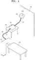
- FIG. 1 illustrates a medical imaging system according to an embodiment.
- reference numeral 109 denotes a bed, e.g., an operating table, on which a patient is positioned during treatment.
- the medical imaging system includes medical equipment 101, a wall-plate converter 103, and a mobile NSC 105.
- the medical equipment 101 is used to treat patients and is provided with a camera (not shown) to generate an image signal.
- the wall-plate converter 103 is mounted on a wall 102 of an indoor space where the medical equipment 101 is located and converts a digital image signal in a specific format into an optical signal for transmission to a display (not shown).
- the optical signal from the wall-plate converter 103 is transmitted to the display via an optical cable 103a.
- An optical receiver (not shown) located at a side of the display then converts the optical signal back into the digital image signal in the specific format and inputs the digital image signal to the display.
- the mobile NSC 105 is mounted on a mobile device 104 and converts the image signal from the medical equipment 101 into the digital image signal in the specific format and inputs a conversion result, i.e., the digital image signal in the specific format, to the wall-plate converter 103.
- the wall-plate converter 103 then supplies direct current (DC) power to the mobile NSC 105 via a connection cable 107 interposed between the mobile NSC 105 and the wall-plate converter 103.
- DC direct current
- the mobile NSC 105 is then connected to the wall-plate converter 103 to immediately receive the DC power therefrom.
- This configuration may solve the conventional problem that it takes a considerable amount of time to supply power to the mobile NSC 105, thereby preventing treatment of a patient being hampered in an emergency situation.
- the digital image signal in the specific format is an image signal in a digital visual interface (DVI) format.
- the connection cable 107 between the mobile NSC 105 and the wall-plate converter 103 is a DVI cable.
- the wall-plate converter 103 supplies the DC power to the mobile NSC 105 via a display data channel (DDC) 5V additional-signal line in the connection cable 107.
- DDC display data channel
- the mobile NSC 105 has a memory for storing a preset identification code therein. After verifying the preset identification code stored in the memory of the mobile NSC 105, the wall-plate converter 103 supplies DC power to the mobile NSC 105.
- the wall-plate converter 103 preferentially supplies DC power to the memory of the mobile NSC 105 via a hot plug detection (HPD) additional-signal line in the connection cable 107.
- HPD hot plug detection
- the image signal from the medical equipment 101 is an image signal in a serial digital interface (SDI) or video graphics array (VGA) format.
- SDI serial digital interface
- VGA video graphics array
- a connection cable 106 interposed between the medical equipment 101 and the mobile NSC 105 is an SDI or VGA cable.
- FIG. 2 is a block diagram of an internal configuration of the mobile NSC 105 described with reference to FIG. 1 when an image signal S SDI in an SDI format is output from the medical equipment 101 in FIG. 1 and an image signal in a DVI format is transmitted to the display.
- reference numerals 201 and 204 respectively represent an SDI cable connector and a DVI cable connector.
- reference numerals 210 through 213 respectively denote a DDC 5V additional-signal terminal, a HPD additional-signal terminal, a serial data SDA terminal, and a serial clock SCL terminal.
- FIGS. 1 and 2 Like reference numerals refer to like elements in FIGS. 1 and 2 .
- the internal configuration and operation of the mobile NSC 105 will now be described with reference to FIGS. 1 and 2 .
- the mobile NSC 105 includes an SDI video decoder 202, the DVI cable connector 204, a DVI video encoder 203, a controller 205, a power supply 207, and an electrically programmable read only memory (EEPROM) 206 as a memory.
- SDI video decoder 202 the DVI cable connector 204
- DVI video encoder 203 the DVI video encoder 203
- controller 205 the DVI video encoder
- a power supply 207 a power supply 207
- EEPROM electrically programmable read only memory
- the SDI video decoder 202 converts the image signal S SID from the medical equipment 101 into a digital red-green-blue (RGB) signal S TTL in a low voltage transistor-transistor logic (LVTTL) format.
- RGB digital red-green-blue
- LTTL low voltage transistor-transistor logic
- the DVI video encoder 203 converts the digital RGB signal S TTL from the SDI video decoder 202 into DVI image-data signals TMDS R, TMDS G, TMDS B, and TMDS CLK that are then output to the DVI cable connector 204.
- the controller 205 such as a microcomputer controls operations of the SDI video decoder 202 and the DVI video encoder 203.
- the power supply 207 operates using 12V DC power, which is supplied via the DDC 5V additional-signal terminal 210 of the DVI cable connector 204, to prevent power collisions and supply 5V DC power to the SDI video decoder 202, the DVI video encoder 203, and the controller 205.
- the EEPROM 206 as a memory stores a preset identification code and operates using 5V DC power, which is supplied via the HPD additional-signal terminal 211 of the DVI cable connector 204, to perform DDC communication via the serial clock SCL terminal 213 and the serial data SDA terminal 212 of the DVI cable connector 204.
- the DDC communication is performed based on an Inter-integrated circuit (I2C) communication protocol.
- I2C Inter-integrated circuit
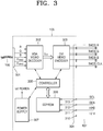
- FIG. 3 is a block diagram of an internal configuration of the mobile NSC 105 described with reference to FIG. 1 when image signals R, G, B, H SYNC , and V SYNC in a VGA format are output from the medical equipment 101 in FIG. 1 and an image signal in a DVI format is transmitted to the display.
- reference numerals 301 and 304 respectively represent a VGA cable connector and a DVI cable connector.
- reference numerals 310 through 313 respectively denote a DDC additional-signal terminal, a HPD additional-signal terminal, a serial data SDA terminal, and a serial clock SCL terminal.
- FIGS. 1 and 3 Like reference numerals refer to like elements in FIGS. 1 and 3 .
- the internal configuration and operation of the mobile NSC 105 will now be described with reference to FIGS. 1 and 3 .
- the mobile NSC 105 includes a VGA video decoder 302, a VGA video encoder 303, the DVI cable connector 304, a controller 305, a power supply 307, and an EEPROM 306 as a memory.
- the VGA video decoder 302 converts the image signals R, G, B, H SYNC , and V SYNC in the VGA format from the medical equipment 101 into a digital RGB signal S TTL in the LVTTL format.
- the DVI video encoder 303 converts the digital RGB signal S TTL from the VGA video decoder 302 into DVI image-data signals TMDS R, TMDS G, TMDS B, and TMDS CLK that are then output to the DVI cable connector 304.
- the controller 305 controls operations of the VGA video decoder 302 and the DVI video encoder 303.
- the power supply 307 operates using 12V DC power, which is supplied via the DDC 5V additional-signal terminal 310 of the DVI cable connector 304, to prevent power collision and supply 5V DC power to the VGA video decoder 302, the DVI video encoder 303, and the controller 305.
- the EEPROM 306 as a memory stores a preset identification code and operates using 5V DC power, which is supplied via the HPD additional-signal terminal 311 of the DVI cable connector 304, to perform DDC communication via the serial clock SCL terminal 313 and the serial data SDA terminal 312 of the DVI cable connector 304.
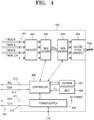
- FIG. 4 is a block diagram of an internal configuration of the wall-plate converter 103 described with reference to FIG. 1 when the connection cable 107 is connected between the mobile NSC 105 and the wall-plate converter 103 in FIG. 1 .
- Like reference numerals refer to like elements in FIGS. 1 and 4 .
- the internal configuration and operation of the wall-plate converter 103 will now be described with reference to FIGS. 1 and 4 .
- the wall-plate converter 103 includes a DVI cable connector 401, an equalizer 402, a transition minimized differential signaling (TMDS) decoder 403, a TMDS encoder 404, an electrophotic converter 405, a power supply 409, an EEPROM 407 as a memory, and a controller 406.
- reference numeral 408 denotes a watch-dog timer (WDT) for inputting a reset signal S RE to the controller 406 when the controller 406 such as a microcomputer performs an abnormal operation.
- WDT watch-dog timer
- the equalizer 402 shapes waveforms of DVI image-data signals TMDS R, TMDS G, TMDS B, and TMDS CLK output from the DVI cable connector 401.
- the TMDS decoder 403 converts the DVI image-data signals TMDS R, TMDS G, TMDS B, and TMDS CLK from the equalizer 402 into a digital RGB signal S TTL in an LVTTL format.
- the TMDS encoder 404 converts the digital RGB signal S TTL from the TMDS decoder 403 into DVI signals TMDS R, TMDS G, TMDS B, and TMDS CLK in a TMDS format.
- the electrophotic converter 405 converts the DVI signals TMDS R, TMDS G, TMDS B, and TMDS CLK from the TMDS encoder 404 into an optical signal and outputs the optical signal to the optical cable 103a.
- the electrophotic converter 405 may reduce the number of optical channels by using Coarse Wavelength Division Multiplexing (CWDM).
- CWDM Coarse Wavelength Division Multiplexing
- the power supply 409 operates using 12V DC power from the outside to prevent power collision and supply 5V power to each component of the wall-plate converter 103.
- the EEPROM 407 stores Extended Display Identification Data (EDID) provided by a display (not shown).
- EDID Extended Display Identification Data
- the controller 406 controls operations of the TMDS decoder 403 and the TMDS encoder 404 according to the EDID stored in the EEPROM 407.
- the TMDS decoder 403 and the TMDS encoder 404 may be additionally used.
- controller 405 performs the following initialization operations.
- the controller 406 controls the power supply 409 to supply 5V DC power to the mobile NSC 105 via a HPD additional-signal line 411. Then, the controller 406 performs DDC communication via a serial clock SCL terminal 413 and a serial data SDA terminal 412 of the DVI cable connector 401. After an identification code of the mobile NSC 105 is verified via the DDC communication, the controller 406 controls the power supply 409 to supply 12V DC power to the mobile NSC 105 via a DDC 5V additional-signal terminal 410 of the DVI cable connector 401.
- FIG. 5 is a flowchart of an algorithm, performed by the controller 406 in FIG. 4 , for supplying power to the mobile NSC 105 in FIG. 1 .
- the algorithm will now be described with reference to FIGS. 4 and 5 .
- the controller 406 controls the power supply 409 to measure a DC voltage of the DDC 5V additional-signal terminal 410 of the DVI cable connector 401 (S501).
- the controller 406 performs operation S503 and its subsequent operations.
- the controller 406 controls the power supply 409 to apply 5V DC power to the HPD additional-signal terminal 411 (S503).
- the controller 406 determines whether the EEPROM (206 of FIG. 2 or 306 of FIG. 3 ) of the mobile NSC 105 is detected while performing DDC communication via the serial clock SCL terminal 413 and the serial data SDA terminal 412 (S504).
- the controller 406 If the EEPROM 206 or 306 is detected in operation S504, the controller 406 reads an identification code stored in the EEPROM 206 or 306 via the DDC communication (S505).
- the read identification code is a preset identification code (S506).
- the controller 406 controls the power supply 409 to apply 12V DC power to the DDC 5V additional-signal terminal 410 of the DVI cable connector 401 (S507).
- a mobile NSC is positioned between medical equipment and a wall-plate converter to be used.
- the position of the mobile NSC may always vary.
- the wall-plate converter supplies DC power to the mobile NSC via a connection cable interposed between the mobile NSC and the wall-plate converter.
- the mobile NSC may then be connected to the wall-plate converter to immediately receive the DC power therefrom.
- the mobile NSC includes a memory for storing a preset identification code therein, and the wall-plate converter is configured to supply DC power to the mobile NSC after verifying the identification code stored in the memory of the mobile NSC.
Landscapes
- Engineering & Computer Science (AREA)
- Theoretical Computer Science (AREA)
- Physics & Mathematics (AREA)
- General Physics & Mathematics (AREA)
- Computer Hardware Design (AREA)
- Human Computer Interaction (AREA)
- General Engineering & Computer Science (AREA)
- Computer Graphics (AREA)
- Multimedia (AREA)
- Signal Processing (AREA)
- Endoscopes (AREA)
- Closed-Circuit Television Systems (AREA)
- Health & Medical Sciences (AREA)
- Life Sciences & Earth Sciences (AREA)
- Biophysics (AREA)
- Pathology (AREA)
- Biomedical Technology (AREA)
- Heart & Thoracic Surgery (AREA)
- Medical Informatics (AREA)
- Molecular Biology (AREA)
- Surgery (AREA)
- Animal Behavior & Ethology (AREA)
- General Health & Medical Sciences (AREA)
- Public Health (AREA)
- Veterinary Medicine (AREA)
Description
- One or more embodiments relate to a medical imaging system, and more particularly, to a medical imaging system including medical equipment, a wall-plate converter, and a mobile near-source converter (NSC).
-
US 2014/253673 A1 discloses a device for converting a video signal from one DVI format to another is provided, the device having an input module configured to convert a first DVI video signal to an HDMI video signal, a converter configured to convert the HDMI video signal to a VGA video signal, and an output module configured to convert the VGA video signal to a second DVI video signal. -
US 2006/246772 A1 relates to an optical DVI cable and optical signal transmission equipment which can prevent the leakage of laser light to the outside. -
US 2003/034963 A1 discloses a digital video signal interface module that enables a distance between a computer having a digital video output and a monitor having a digital video input to length and comprises a laser driver and a laser diode receiving digital video signals of Red (R), Green (G), Blue (B), Clock (C) outputted from a computer and converting the signals to a laser singals, respectively; a photodiode (PD) receiving the respective laser signals and restoring to electric signals; a photodiode amplifier amplifying the signals of the photodiode and transferring the signals to a Liquid Crystal Display (LCD) monitor; a plurality of an optic fiber installed between the respective laser diode and the respective phoptodiode and transferring the laser signals;; and a power supply line and a ground voltage line installed between the computer and the LCD monitor along the optic fibers and supplying a power voltge to the laser driver and the PD amplifier. -
WO 2008/084936 A1 concerns a digital image system includes a host device, a transmission/reception reinforcement device, and a display device. Each of the first power-supply switching unit and the second power-supply switching unit includes an external power-supply input terminal, an internal power-supply input terminal, a power-supply output terminal, and a switch. -
EP 2 824 658 A2 discloses a dual mode display-port connector including a host-side auxiliary interface, a display-side auxiliary interface, and a cable. - A general medical imaging system includes medical equipment, a wall-plate converter, and a mobile near-source converter (NSC).
- In the general medical imaging system, the medical equipment includes a camera to generate an image signal.
- The wall-plate converter is mounted on a wall of a room where the medical equipment is located and converts a digital image signal in a specific format into an optical signal for transmission to a display.
- The mobile NSC is mounted on a mobile device to convert the image signal from the medical equipment into the digital image signal in the specific format and input a conversion result, i.e., the digital image signal in the specific format, to the wall-plate converter.
- In a medical imaging system as described above, a mobile NSC may be positioned between medical equipment and a wall-plate converter to be used. Thus, depending on locations of the medical equipment and the wall-plate converter, the position of the mobile NSC may vary.
- When a power outlet is located far away from the mobile NSC, it may take a considerable amount of time to supply direct current (DC) power to the mobile NSC. This may possibly hamper treatment of an emergency patient.
- The above-described problems associated with the related art have been known to and prompted the inventor to derive the present invention or have been learned in the process of deriving the same. However, the problems are not necessarily considered as being known to the general public before the filing date of the invention.
- According to the invention, a medical imaging system according to claim 1 is provided.
- One or more embodiments include a medical imaging system adapted to prevent treatment of a patient being hampered in an emergency situation.
- Additional aspects will be set forth in part in the description which follows and, in part, will be apparent from the description, or may be learned by practice of the presented embodiments.
- The wall-plate converter is further configured to preferentially supply DC power to the memory of the mobile NSC via a hot plug detection (HPD) additional-signal line in the connection cable.
- The mobile NSC is positioned between the medical equipment and the wall-plate converter to be used. In other words, the position of the mobile NSC may always vary.
- In the medical imaging system according to the embodiment, the wall-plate converter supplies DC power to the mobile NSC via the connection cable interposed between the mobile NSC and the wall-plate converter. The mobile NSC may then be connected to the wall-plate converter to immediately receive the DC power therefrom. With this configuration, it is possible to solve the conventional problem that it may take a considerable amount of time to supply power to the mobile NSC, thereby preventing treatment of a patient being hampered in an emergency situation.
- Furthermore, as described above, the mobile NSC includes the memory for storing the set identification code therein, and the wall-plate converter is further configured to supply DC power to the mobile NSC after verifying the identification code stored in the memory of the mobile NSC.
- These and/or other aspects will become apparent and more readily appreciated from the following description of the embodiments, taken in conjunction with the accompanying drawings in which:
-
FIG. 1 illustrates a medical imaging system according to an embodiment; -
FIG. 2 is a block diagram of an internal configuration of a mobile near-source converter (NSC) included in the medical imaging system ofFIG. 1 when an image signal in a serial digital interface (SDI) format is output from medical equipment inFIG. 1 and an image signal in a digital visual interface (DVI) format is transmitted to a display; -
FIG. 3 is a block diagram of an internal configuration of the mobile NSC included in the medical imaging system ofFIG. 1 when an image signal in a video graphics array (VGA) format is output from the medical equipment inFIG. 1 and an image signal in a DVI format is transmitted to a display; -
FIG. 4 is a block diagram of an internal configuration of a wall-plate converter included in the medical imaging system ofFIG. 1 when a DVI cable is connected between the mobile NSC and the wall-plate converter inFIG. 1 ; and -
FIG. 5 is a flowchart of an algorithm, performed by a controller inFIG. 4 , for supplying power to a mobile NSC. - The following description and the accompanying drawings are intended to understand operations according to the present disclosure, and parts that can be easily implemented by one of ordinary skill in the art are omitted.
- Furthermore, the present specification and the figures are not provided for purposes of limitation, and the scope of the inventive concept should be defined by the claims. The terms used in this specification are chosen to best describe the inventive concept and should be interpreted based on the meaning and concept corresponding to technical aspects of the present disclosure.
- Hereinafter, embodiments will be described more fully with reference to the attached drawings.
-
FIG. 1 illustrates a medical imaging system according to an embodiment. InFIG. 1 ,reference numeral 109 denotes a bed, e.g., an operating table, on which a patient is positioned during treatment. - Referring to
FIG. 1 , the medical imaging system according to the present embodiment includesmedical equipment 101, a wall-plate converter 103, and amobile NSC 105. - The
medical equipment 101 is used to treat patients and is provided with a camera (not shown) to generate an image signal. - The wall-
plate converter 103 is mounted on awall 102 of an indoor space where themedical equipment 101 is located and converts a digital image signal in a specific format into an optical signal for transmission to a display (not shown). In other words, the optical signal from the wall-plate converter 103 is transmitted to the display via anoptical cable 103a. An optical receiver (not shown) located at a side of the display then converts the optical signal back into the digital image signal in the specific format and inputs the digital image signal to the display. - The
mobile NSC 105 is mounted on amobile device 104 and converts the image signal from themedical equipment 101 into the digital image signal in the specific format and inputs a conversion result, i.e., the digital image signal in the specific format, to the wall-plate converter 103. - Here, the wall-
plate converter 103 then supplies direct current (DC) power to the mobile NSC 105 via aconnection cable 107 interposed between themobile NSC 105 and the wall-plate converter 103. - The
mobile NSC 105 is then connected to the wall-plate converter 103 to immediately receive the DC power therefrom. This configuration may solve the conventional problem that it takes a considerable amount of time to supply power to themobile NSC 105, thereby preventing treatment of a patient being hampered in an emergency situation. - According to the present embodiment, the digital image signal in the specific format is an image signal in a digital visual interface (DVI) format. Furthermore, the
connection cable 107 between themobile NSC 105 and the wall-plate converter 103 is a DVI cable. - The wall-
plate converter 103 supplies the DC power to the mobile NSC 105 via a display data channel (DDC) 5V additional-signal line in theconnection cable 107. - The
mobile NSC 105 has a memory for storing a preset identification code therein. After verifying the preset identification code stored in the memory of themobile NSC 105, the wall-plate converter 103 supplies DC power to themobile NSC 105. - Thus, according to the present embodiment, even when an imaging device other than the mobile NSC 105 connects to the wall-
plate converter 103, power collision caused by the other imaging device may be prevented. - The wall-
plate converter 103 preferentially supplies DC power to the memory of themobile NSC 105 via a hot plug detection (HPD) additional-signal line in theconnection cable 107. - According to the present embodiment, the image signal from the
medical equipment 101 is an image signal in a serial digital interface (SDI) or video graphics array (VGA) format. In other words, aconnection cable 106 interposed between themedical equipment 101 and themobile NSC 105 is an SDI or VGA cable. -
FIG. 2 is a block diagram of an internal configuration of themobile NSC 105 described with reference toFIG. 1 when an image signal SSDI in an SDI format is output from themedical equipment 101 inFIG. 1 and an image signal in a DVI format is transmitted to the display. InFIG. 2 ,reference numerals DVI cable connector 204,reference numerals 210 through 213 respectively denote aDDC 5V additional-signal terminal, a HPD additional-signal terminal, a serial data SDA terminal, and a serial clock SCL terminal. - Like reference numerals refer to like elements in
FIGS. 1 and2 . The internal configuration and operation of themobile NSC 105 will now be described with reference toFIGS. 1 and2 . - Referring to
FIGS. 1 and2 , themobile NSC 105 includes anSDI video decoder 202, theDVI cable connector 204, aDVI video encoder 203, acontroller 205, apower supply 207, and an electrically programmable read only memory (EEPROM) 206 as a memory. - The
SDI video decoder 202 converts the image signal SSID from themedical equipment 101 into a digital red-green-blue (RGB) signal STTL in a low voltage transistor-transistor logic (LVTTL) format. - The
DVI video encoder 203 converts the digital RGB signal STTL from theSDI video decoder 202 into DVI image-data signals TMDS R, TMDS G, TMDS B, and TMDS CLK that are then output to theDVI cable connector 204. - The
controller 205 such as a microcomputer controls operations of theSDI video decoder 202 and theDVI video encoder 203. - The
power supply 207 operates using 12V DC power, which is supplied via theDDC 5V additional-signal terminal 210 of theDVI cable connector 204, to prevent power collisions and supply 5V DC power to theSDI video decoder 202, theDVI video encoder 203, and thecontroller 205. - The
EEPROM 206 as a memory stores a preset identification code and operates using 5V DC power, which is supplied via the HPD additional-signal terminal 211 of theDVI cable connector 204, to perform DDC communication via the serialclock SCL terminal 213 and the serialdata SDA terminal 212 of theDVI cable connector 204. According to the present embodiment, the DDC communication is performed based on an Inter-integrated circuit (I2C) communication protocol. -
FIG. 3 is a block diagram of an internal configuration of themobile NSC 105 described with reference toFIG. 1 when image signals R, G, B, HSYNC, and VSYNC in a VGA format are output from themedical equipment 101 inFIG. 1 and an image signal in a DVI format is transmitted to the display. InFIG. 3 ,reference numerals DVI cable connector 304,reference numerals 310 through 313 respectively denote a DDC additional-signal terminal, a HPD additional-signal terminal, a serial data SDA terminal, and a serial clock SCL terminal. - Like reference numerals refer to like elements in
FIGS. 1 and3 . The internal configuration and operation of themobile NSC 105 will now be described with reference toFIGS. 1 and3 . - Referring to
FIGS. 1 and3 , themobile NSC 105 includes aVGA video decoder 302, aVGA video encoder 303, theDVI cable connector 304, acontroller 305, apower supply 307, and anEEPROM 306 as a memory. - The
VGA video decoder 302 converts the image signals R, G, B, HSYNC, and VSYNC in the VGA format from themedical equipment 101 into a digital RGB signal STTL in the LVTTL format. - The
DVI video encoder 303 converts the digital RGB signal STTL from theVGA video decoder 302 into DVI image-data signals TMDS R, TMDS G, TMDS B, and TMDS CLK that are then output to theDVI cable connector 304. - The
controller 305 controls operations of theVGA video decoder 302 and theDVI video encoder 303. - The
power supply 307 operates using 12V DC power, which is supplied via theDDC 5V additional-signal terminal 310 of theDVI cable connector 304, to prevent power collision and supply 5V DC power to theVGA video decoder 302, theDVI video encoder 303, and thecontroller 305. - The
EEPROM 306 as a memory stores a preset identification code and operates using 5V DC power, which is supplied via the HPD additional-signal terminal 311 of theDVI cable connector 304, to perform DDC communication via the serialclock SCL terminal 313 and the serialdata SDA terminal 312 of theDVI cable connector 304. -
FIG. 4 is a block diagram of an internal configuration of the wall-plate converter 103 described with reference toFIG. 1 when theconnection cable 107 is connected between themobile NSC 105 and the wall-plate converter 103 inFIG. 1 . Like reference numerals refer to like elements inFIGS. 1 and4 . The internal configuration and operation of the wall-plate converter 103 will now be described with reference toFIGS. 1 and4 . - Referring to
FIGS. 1 and4 , the wall-plate converter 103 includes aDVI cable connector 401, anequalizer 402, a transition minimized differential signaling (TMDS)decoder 403, aTMDS encoder 404, anelectrophotic converter 405, apower supply 409, anEEPROM 407 as a memory, and acontroller 406. InFIG. 4 ,reference numeral 408 denotes a watch-dog timer (WDT) for inputting a reset signal SRE to thecontroller 406 when thecontroller 406 such as a microcomputer performs an abnormal operation. - The
equalizer 402 shapes waveforms of DVI image-data signals TMDS R, TMDS G, TMDS B, and TMDS CLK output from theDVI cable connector 401. - The
TMDS decoder 403 converts the DVI image-data signals TMDS R, TMDS G, TMDS B, and TMDS CLK from theequalizer 402 into a digital RGB signal STTL in an LVTTL format. - The
TMDS encoder 404 converts the digital RGB signal STTL from theTMDS decoder 403 into DVI signals TMDS R, TMDS G, TMDS B, and TMDS CLK in a TMDS format. - The
electrophotic converter 405 converts the DVI signals TMDS R, TMDS G, TMDS B, and TMDS CLK from theTMDS encoder 404 into an optical signal and outputs the optical signal to theoptical cable 103a. In this case, theelectrophotic converter 405 may reduce the number of optical channels by using Coarse Wavelength Division Multiplexing (CWDM). - The
power supply 409 operates using 12V DC power from the outside to prevent power collision and supply 5V power to each component of the wall-plate converter 103. - The
EEPROM 407 stores Extended Display Identification Data (EDID) provided by a display (not shown). - The
controller 406 controls operations of theTMDS decoder 403 and theTMDS encoder 404 according to the EDID stored in theEEPROM 407. Thus, theTMDS decoder 403 and theTMDS encoder 404 may be additionally used. - In addition, the
controller 405 performs the following initialization operations. - The
controller 406 controls thepower supply 409 to supply 5V DC power to themobile NSC 105 via a HPD additional-signal line 411. Then, thecontroller 406 performs DDC communication via a serialclock SCL terminal 413 and a serialdata SDA terminal 412 of theDVI cable connector 401. After an identification code of themobile NSC 105 is verified via the DDC communication, thecontroller 406 controls thepower supply 409 to supply 12V DC power to themobile NSC 105 via aDDC 5V additional-signal terminal 410 of theDVI cable connector 401. - Thus, even when an imaging device other than the
mobile NSC 105 connects to the wall-plate converter 103, power collision caused by the other imaging device may be prevented. Operations of thecontroller 406 related to this case will now be described with reference toFIG. 5 . -
FIG. 5 is a flowchart of an algorithm, performed by thecontroller 406 inFIG. 4 , for supplying power to themobile NSC 105 inFIG. 1 . The algorithm will now be described with reference toFIGS. 4 and5 . - Referring to
FIGS. 4 and5 , first, thecontroller 406 controls thepower supply 409 to measure a DC voltage of theDDC 5V additional-signal terminal 410 of the DVI cable connector 401 (S501). - If the DC voltage of the
DDC 5V additional-signal terminal 410 is not applied (S502), thecontroller 406 performs operation S503 and its subsequent operations. - The
controller 406 controls thepower supply 409 to apply 5V DC power to the HPD additional-signal terminal 411 (S503). - Then, the
controller 406 determines whether the EEPROM (206 ofFIG. 2 or 306 ofFIG. 3 ) of themobile NSC 105 is detected while performing DDC communication via the serialclock SCL terminal 413 and the serial data SDA terminal 412 (S504). - If the
EEPROM controller 406 reads an identification code stored in theEEPROM - Subsequently, it is determined whether the read identification code is a preset identification code (S506).
- If it is determined that the read identification code is the preset identification code, the
controller 406 controls thepower supply 409 to apply 12V DC power to theDDC 5V additional-signal terminal 410 of the DVI cable connector 401 (S507). - Operations S504 through S507 are repeated periodically until an end signal is generated (S508).
- As described above, a mobile NSC is positioned between medical equipment and a wall-plate converter to be used. In other words, the position of the mobile NSC may always vary.
- In a medical imaging system according to an embodiment, the wall-plate converter supplies DC power to the mobile NSC via a connection cable interposed between the mobile NSC and the wall-plate converter. The mobile NSC may then be connected to the wall-plate converter to immediately receive the DC power therefrom. With this configuration, it is possible to solve the conventional problem that it may take a considerable amount of time to supply power to the mobile NSC, thereby preventing treatment of a patient being hampered in an emergency situation.
- Furthermore, the mobile NSC includes a memory for storing a preset identification code therein, and the wall-plate converter is configured to supply DC power to the mobile NSC after verifying the identification code stored in the memory of the mobile NSC.
- Thus, even when an imaging device that is other than the mobile NSC connects to the wall-plate converter, power collision caused by the other imaging device may be prevented.
- While one or more embodiments have been described with reference to the figures, it will be understood by those of ordinary skill in the art that various changes in form and details may be made therein without departing from the scope of the disclosure as defined by the following claims.
- Thus, it should be understood that the exemplary embodiments described therein should be considered in a descriptive sense only and not for purposes of limitation. The scope of the inventive concept is defined not by the detailed description thereof but by the appended claims, and all differences within the scope of the appended claims and their equivalents will be construed as being included in the present inventive concept.
Claims (2)
- A medical imaging system comprising:medical equipment (101) including a camera to generate an image signal;a wall-plate converter (103) mounted on a wall (102) of an indoor space where the medical equipment is located and configured to convert a digital image signal in a specific format into an optical signal and transmit the optical signal to a display; anda mobile near-source converter, NSC, (105) mounted on a mobile device (104) to convert the image signal from the medical equipment into the digital image signal in the specific format and input, to the wall-plate converter (103), the digital image signal in the specific format that is a result of the converting, wherein the digital image signal in the specific format is an image signal in a digital visual interface, DVI, format, and
wherein a connection cable (107) is interposed between the mobile NSC and the wall-plate converter is a DVI cable, characterized in that
the wall plate converter (103) is further configured to supply direct current, DC, power to the mobile NSC (105) via the connection cable interposed between the mobile NSC and the wall-plate converter, wherein the wall-plate converter (103) is further configured to supply the DC power to the mobile NSC (105) via a display data channel, DDC, 5V additional-signal line in the connection cable (107), wherein the mobile NSC (105) comprises a memory (206, 306) for storing a preset identification code therein,wherein the wall-plate converter is adapted to read the identification code stored in the memory;wherein the wall-plate converter is further configured to supply the DC power to the mobile NSC (105) after verifying the preset identification code stored in the memory of the mobile NSC. - The medical imaging system of claim 1, wherein the wall-plate converter is further configured to preferentially supply DC power to the memory of the mobile NSC (105) via a hot plug detection, HPD, additional-signal line in the connection cable (107).
Applications Claiming Priority (1)
| Application Number | Priority Date | Filing Date | Title |
|---|---|---|---|
| KR1020160013545A KR101754335B1 (en) | 2016-02-03 | 2016-02-03 | Medical imaging system |
Publications (2)
| Publication Number | Publication Date |
|---|---|
| EP3203372A1 EP3203372A1 (en) | 2017-08-09 |
| EP3203372B1 true EP3203372B1 (en) | 2018-10-03 |
Family
ID=57821817
Family Applications (1)
| Application Number | Title | Priority Date | Filing Date |
|---|---|---|---|
| EP17151211.4A Active EP3203372B1 (en) | 2016-02-03 | 2017-01-12 | Medical imaging system |
Country Status (3)
| Country | Link |
|---|---|
| US (1) | US9892711B2 (en) |
| EP (1) | EP3203372B1 (en) |
| KR (1) | KR101754335B1 (en) |
Families Citing this family (1)
| Publication number | Priority date | Publication date | Assignee | Title |
|---|---|---|---|---|
| EP3721439A4 (en) | 2017-12-06 | 2021-06-30 | Medicapture, Inc. | IMAGING SYSTEM AND METHOD FOR PROCESSING SEVERAL IMAGE FORMATS |
Family Cites Families (12)
| Publication number | Priority date | Publication date | Assignee | Title |
|---|---|---|---|---|
| JP2549506B2 (en) | 1985-03-12 | 1996-10-30 | 富士写真フイルム株式会社 | Medical diagnostic imaging system |
| KR100402409B1 (en) * | 2001-05-26 | 2003-10-30 | (주)오피트정보통신 | Digital Vidio Signal Interface Module For Transmitting Long Distance |
| JP3745279B2 (en) | 2002-01-16 | 2006-02-15 | 日本航空電子工業株式会社 | DVI optical extension cable connection and external power input confirmation system |
| US6941395B1 (en) * | 2002-09-24 | 2005-09-06 | Monster Cable Products, Inc. | DVI cable interface |
| KR100667748B1 (en) | 2002-10-08 | 2007-01-11 | 삼성전자주식회사 | Display recognition information output device and method according to connector type |
| JP4193067B2 (en) * | 2005-04-28 | 2008-12-10 | 住友電気工業株式会社 | Optical DVI cable and optical signal transmission device |
| KR100584621B1 (en) * | 2005-07-19 | 2006-05-30 | 삼성전자주식회사 | Display recognition information output device and method according to connector type |
| US20070225590A1 (en) * | 2006-01-13 | 2007-09-27 | Boston Scientific Scimed, Inc. | Control panel for a medical imaging system |
| KR100869702B1 (en) * | 2007-01-11 | 2008-11-21 | 옵티시스 주식회사 | Digital imaging system for transmitting digital video data |
| US9312704B2 (en) * | 2012-01-09 | 2016-04-12 | Voxx International Corporation | USB wall plate charger |
| US20140253673A1 (en) * | 2013-03-05 | 2014-09-11 | Summit Imaging, Inc. | Video output conversion system |
| KR101414447B1 (en) * | 2013-07-02 | 2014-07-08 | 옵티시스 주식회사 | Dual mode Display-Port connector |
-
2016
- 2016-02-03 KR KR1020160013545A patent/KR101754335B1/en active Active
-
2017
- 2017-01-12 EP EP17151211.4A patent/EP3203372B1/en active Active
- 2017-02-03 US US15/423,751 patent/US9892711B2/en active Active
Non-Patent Citations (1)
| Title |
|---|
| None * |
Also Published As
| Publication number | Publication date |
|---|---|
| US9892711B2 (en) | 2018-02-13 |
| US20170221446A1 (en) | 2017-08-03 |
| KR101754335B1 (en) | 2017-07-07 |
| EP3203372A1 (en) | 2017-08-09 |
Similar Documents
| Publication | Publication Date | Title |
|---|---|---|
| US7406607B2 (en) | Controller for a host device and a monitoring device connected on the basis of DVI standard | |
| US10327049B2 (en) | Cable and electronic apparatus | |
| EP3058721B1 (en) | Digital-image transmission apparatus which performs communication, self-diagnosis, and control | |
| CN107409242B (en) | Method and apparatus for transmitting/receiving power using HDMI | |
| US9612990B2 (en) | Dual mode display-port connector for optical communication | |
| US10721093B2 (en) | Adapter apparatus, electronic apparatus and communication method | |
| JP5007657B2 (en) | COMMUNICATION SYSTEM, ELECTRONIC DEVICE, AND COMMUNICATION METHOD | |
| US10509614B2 (en) | Video display apparatus-apparatus communication | |
| US20150347077A1 (en) | Display device, multi-display system and multi-display method | |
| CN111742360B (en) | Image display device and image display method | |
| US20190064899A1 (en) | Electronic apparatus and cable | |
| JP6949860B2 (en) | HDMI optical cable and HDMI optical converter | |
| KR20180005156A (en) | Method and apparatus for transmitting and receiving power using HDMI | |
| US11662393B2 (en) | Cable, method for controlling cable, transmission device, method for controlling transmission device, reception device, and method for controlling reception device | |
| US9892711B2 (en) | Medical imaging system | |
| TW202110169A (en) | Circuit and method for use in a first display device to facilitate communication with a second display device, and display communication system | |
| JP4345652B2 (en) | Digital video signal interface module | |
| JP4470560B2 (en) | Signal transmission device | |
| JP2004191454A (en) | Image transmission system, host device, monitor device, and image transmission method | |
| JP2020061030A (en) | Display device, method of detecting breakage of cable in display device, information processing device, and program |
Legal Events
| Date | Code | Title | Description |
|---|---|---|---|
| PUAI | Public reference made under article 153(3) epc to a published international application that has entered the european phase |
Free format text: ORIGINAL CODE: 0009012 |
|
| STAA | Information on the status of an ep patent application or granted ep patent |
Free format text: STATUS: REQUEST FOR EXAMINATION WAS MADE |
|
| 17P | Request for examination filed |
Effective date: 20170112 |
|
| AK | Designated contracting states |
Kind code of ref document: A1 Designated state(s): AL AT BE BG CH CY CZ DE DK EE ES FI FR GB GR HR HU IE IS IT LI LT LU LV MC MK MT NL NO PL PT RO RS SE SI SK SM TR |
|
| AX | Request for extension of the european patent |
Extension state: BA ME |
|
| RIC1 | Information provided on ipc code assigned before grant |
Ipc: G09G 3/20 20060101ALI20180315BHEP Ipc: H04N 11/20 20060101ALI20180315BHEP Ipc: G09G 5/00 20060101ALI20180315BHEP Ipc: G09G 5/36 20060101ALI20180315BHEP Ipc: G06F 3/147 20060101AFI20180315BHEP |
|
| GRAP | Despatch of communication of intention to grant a patent |
Free format text: ORIGINAL CODE: EPIDOSNIGR1 |
|
| STAA | Information on the status of an ep patent application or granted ep patent |
Free format text: STATUS: GRANT OF PATENT IS INTENDED |
|
| INTG | Intention to grant announced |
Effective date: 20180504 |
|
| RIN1 | Information on inventor provided before grant (corrected) |
Inventor name: YANG, DONG PYEONG Inventor name: HA, DOO SOO Inventor name: KO, JAE CHUL Inventor name: BYUN, WON GIL |
|
| GRAS | Grant fee paid |
Free format text: ORIGINAL CODE: EPIDOSNIGR3 |
|
| GRAA | (expected) grant |
Free format text: ORIGINAL CODE: 0009210 |
|
| STAA | Information on the status of an ep patent application or granted ep patent |
Free format text: STATUS: THE PATENT HAS BEEN GRANTED |
|
| AK | Designated contracting states |
Kind code of ref document: B1 Designated state(s): AL AT BE BG CH CY CZ DE DK EE ES FI FR GB GR HR HU IE IS IT LI LT LU LV MC MK MT NL NO PL PT RO RS SE SI SK SM TR |
|
| REG | Reference to a national code |
Ref country code: GB Ref legal event code: FG4D |
|
| REG | Reference to a national code |
Ref country code: CH Ref legal event code: EP Ref country code: AT Ref legal event code: REF Ref document number: 1049341 Country of ref document: AT Kind code of ref document: T Effective date: 20181015 |
|
| REG | Reference to a national code |
Ref country code: IE Ref legal event code: FG4D Ref country code: DE Ref legal event code: R096 Ref document number: 602017000549 Country of ref document: DE |
|
| REG | Reference to a national code |
Ref country code: FR Ref legal event code: PLFP Year of fee payment: 3 |
|
| REG | Reference to a national code |
Ref country code: NL Ref legal event code: MP Effective date: 20181003 |
|
| REG | Reference to a national code |
Ref country code: LT Ref legal event code: MG4D |
|
| REG | Reference to a national code |
Ref country code: AT Ref legal event code: MK05 Ref document number: 1049341 Country of ref document: AT Kind code of ref document: T Effective date: 20181003 |
|
| PG25 | Lapsed in a contracting state [announced via postgrant information from national office to epo] |
Ref country code: NL Free format text: LAPSE BECAUSE OF FAILURE TO SUBMIT A TRANSLATION OF THE DESCRIPTION OR TO PAY THE FEE WITHIN THE PRESCRIBED TIME-LIMIT Effective date: 20181003 |
|
| PG25 | Lapsed in a contracting state [announced via postgrant information from national office to epo] |
Ref country code: CZ Free format text: LAPSE BECAUSE OF FAILURE TO SUBMIT A TRANSLATION OF THE DESCRIPTION OR TO PAY THE FEE WITHIN THE PRESCRIBED TIME-LIMIT Effective date: 20181003 Ref country code: FI Free format text: LAPSE BECAUSE OF FAILURE TO SUBMIT A TRANSLATION OF THE DESCRIPTION OR TO PAY THE FEE WITHIN THE PRESCRIBED TIME-LIMIT Effective date: 20181003 Ref country code: LV Free format text: LAPSE BECAUSE OF FAILURE TO SUBMIT A TRANSLATION OF THE DESCRIPTION OR TO PAY THE FEE WITHIN THE PRESCRIBED TIME-LIMIT Effective date: 20181003 Ref country code: HR Free format text: LAPSE BECAUSE OF FAILURE TO SUBMIT A TRANSLATION OF THE DESCRIPTION OR TO PAY THE FEE WITHIN THE PRESCRIBED TIME-LIMIT Effective date: 20181003 Ref country code: AT Free format text: LAPSE BECAUSE OF FAILURE TO SUBMIT A TRANSLATION OF THE DESCRIPTION OR TO PAY THE FEE WITHIN THE PRESCRIBED TIME-LIMIT Effective date: 20181003 Ref country code: LT Free format text: LAPSE BECAUSE OF FAILURE TO SUBMIT A TRANSLATION OF THE DESCRIPTION OR TO PAY THE FEE WITHIN THE PRESCRIBED TIME-LIMIT Effective date: 20181003 Ref country code: BG Free format text: LAPSE BECAUSE OF FAILURE TO SUBMIT A TRANSLATION OF THE DESCRIPTION OR TO PAY THE FEE WITHIN THE PRESCRIBED TIME-LIMIT Effective date: 20190103 Ref country code: PL Free format text: LAPSE BECAUSE OF FAILURE TO SUBMIT A TRANSLATION OF THE DESCRIPTION OR TO PAY THE FEE WITHIN THE PRESCRIBED TIME-LIMIT Effective date: 20181003 Ref country code: ES Free format text: LAPSE BECAUSE OF FAILURE TO SUBMIT A TRANSLATION OF THE DESCRIPTION OR TO PAY THE FEE WITHIN THE PRESCRIBED TIME-LIMIT Effective date: 20181003 Ref country code: NO Free format text: LAPSE BECAUSE OF FAILURE TO SUBMIT A TRANSLATION OF THE DESCRIPTION OR TO PAY THE FEE WITHIN THE PRESCRIBED TIME-LIMIT Effective date: 20190103 Ref country code: IS Free format text: LAPSE BECAUSE OF FAILURE TO SUBMIT A TRANSLATION OF THE DESCRIPTION OR TO PAY THE FEE WITHIN THE PRESCRIBED TIME-LIMIT Effective date: 20190203 |
|
| PG25 | Lapsed in a contracting state [announced via postgrant information from national office to epo] |
Ref country code: AL Free format text: LAPSE BECAUSE OF FAILURE TO SUBMIT A TRANSLATION OF THE DESCRIPTION OR TO PAY THE FEE WITHIN THE PRESCRIBED TIME-LIMIT Effective date: 20181003 Ref country code: PT Free format text: LAPSE BECAUSE OF FAILURE TO SUBMIT A TRANSLATION OF THE DESCRIPTION OR TO PAY THE FEE WITHIN THE PRESCRIBED TIME-LIMIT Effective date: 20190203 Ref country code: GR Free format text: LAPSE BECAUSE OF FAILURE TO SUBMIT A TRANSLATION OF THE DESCRIPTION OR TO PAY THE FEE WITHIN THE PRESCRIBED TIME-LIMIT Effective date: 20190104 Ref country code: RS Free format text: LAPSE BECAUSE OF FAILURE TO SUBMIT A TRANSLATION OF THE DESCRIPTION OR TO PAY THE FEE WITHIN THE PRESCRIBED TIME-LIMIT Effective date: 20181003 Ref country code: SE Free format text: LAPSE BECAUSE OF FAILURE TO SUBMIT A TRANSLATION OF THE DESCRIPTION OR TO PAY THE FEE WITHIN THE PRESCRIBED TIME-LIMIT Effective date: 20181003 |
|
| REG | Reference to a national code |
Ref country code: DE Ref legal event code: R097 Ref document number: 602017000549 Country of ref document: DE |
|
| PG25 | Lapsed in a contracting state [announced via postgrant information from national office to epo] |
Ref country code: IT Free format text: LAPSE BECAUSE OF FAILURE TO SUBMIT A TRANSLATION OF THE DESCRIPTION OR TO PAY THE FEE WITHIN THE PRESCRIBED TIME-LIMIT Effective date: 20181003 Ref country code: DK Free format text: LAPSE BECAUSE OF FAILURE TO SUBMIT A TRANSLATION OF THE DESCRIPTION OR TO PAY THE FEE WITHIN THE PRESCRIBED TIME-LIMIT Effective date: 20181003 |
|
| PLBE | No opposition filed within time limit |
Free format text: ORIGINAL CODE: 0009261 |
|
| STAA | Information on the status of an ep patent application or granted ep patent |
Free format text: STATUS: NO OPPOSITION FILED WITHIN TIME LIMIT |
|
| PG25 | Lapsed in a contracting state [announced via postgrant information from national office to epo] |
Ref country code: EE Free format text: LAPSE BECAUSE OF FAILURE TO SUBMIT A TRANSLATION OF THE DESCRIPTION OR TO PAY THE FEE WITHIN THE PRESCRIBED TIME-LIMIT Effective date: 20181003 Ref country code: SM Free format text: LAPSE BECAUSE OF FAILURE TO SUBMIT A TRANSLATION OF THE DESCRIPTION OR TO PAY THE FEE WITHIN THE PRESCRIBED TIME-LIMIT Effective date: 20181003 Ref country code: SK Free format text: LAPSE BECAUSE OF FAILURE TO SUBMIT A TRANSLATION OF THE DESCRIPTION OR TO PAY THE FEE WITHIN THE PRESCRIBED TIME-LIMIT Effective date: 20181003 Ref country code: MC Free format text: LAPSE BECAUSE OF FAILURE TO SUBMIT A TRANSLATION OF THE DESCRIPTION OR TO PAY THE FEE WITHIN THE PRESCRIBED TIME-LIMIT Effective date: 20181003 Ref country code: RO Free format text: LAPSE BECAUSE OF FAILURE TO SUBMIT A TRANSLATION OF THE DESCRIPTION OR TO PAY THE FEE WITHIN THE PRESCRIBED TIME-LIMIT Effective date: 20181003 |
|
| 26N | No opposition filed |
Effective date: 20190704 |
|
| PG25 | Lapsed in a contracting state [announced via postgrant information from national office to epo] |
Ref country code: LU Free format text: LAPSE BECAUSE OF NON-PAYMENT OF DUE FEES Effective date: 20190112 |
|
| REG | Reference to a national code |
Ref country code: BE Ref legal event code: MM Effective date: 20190131 |
|
| REG | Reference to a national code |
Ref country code: IE Ref legal event code: MM4A |
|
| PG25 | Lapsed in a contracting state [announced via postgrant information from national office to epo] |
Ref country code: SI Free format text: LAPSE BECAUSE OF FAILURE TO SUBMIT A TRANSLATION OF THE DESCRIPTION OR TO PAY THE FEE WITHIN THE PRESCRIBED TIME-LIMIT Effective date: 20181003 |
|
| PG25 | Lapsed in a contracting state [announced via postgrant information from national office to epo] |
Ref country code: BE Free format text: LAPSE BECAUSE OF NON-PAYMENT OF DUE FEES Effective date: 20190131 |
|
| PG25 | Lapsed in a contracting state [announced via postgrant information from national office to epo] |
Ref country code: IE Free format text: LAPSE BECAUSE OF NON-PAYMENT OF DUE FEES Effective date: 20190112 |
|
| PG25 | Lapsed in a contracting state [announced via postgrant information from national office to epo] |
Ref country code: TR Free format text: LAPSE BECAUSE OF FAILURE TO SUBMIT A TRANSLATION OF THE DESCRIPTION OR TO PAY THE FEE WITHIN THE PRESCRIBED TIME-LIMIT Effective date: 20181003 |
|
| PG25 | Lapsed in a contracting state [announced via postgrant information from national office to epo] |
Ref country code: MT Free format text: LAPSE BECAUSE OF NON-PAYMENT OF DUE FEES Effective date: 20190112 |
|
| REG | Reference to a national code |
Ref country code: CH Ref legal event code: PL |
|
| PG25 | Lapsed in a contracting state [announced via postgrant information from national office to epo] |
Ref country code: CH Free format text: LAPSE BECAUSE OF NON-PAYMENT OF DUE FEES Effective date: 20200131 Ref country code: LI Free format text: LAPSE BECAUSE OF NON-PAYMENT OF DUE FEES Effective date: 20200131 |
|
| PG25 | Lapsed in a contracting state [announced via postgrant information from national office to epo] |
Ref country code: CY Free format text: LAPSE BECAUSE OF FAILURE TO SUBMIT A TRANSLATION OF THE DESCRIPTION OR TO PAY THE FEE WITHIN THE PRESCRIBED TIME-LIMIT Effective date: 20181003 |
|
| PG25 | Lapsed in a contracting state [announced via postgrant information from national office to epo] |
Ref country code: HU Free format text: LAPSE BECAUSE OF FAILURE TO SUBMIT A TRANSLATION OF THE DESCRIPTION OR TO PAY THE FEE WITHIN THE PRESCRIBED TIME-LIMIT; INVALID AB INITIO Effective date: 20170112 |
|
| PG25 | Lapsed in a contracting state [announced via postgrant information from national office to epo] |
Ref country code: MK Free format text: LAPSE BECAUSE OF FAILURE TO SUBMIT A TRANSLATION OF THE DESCRIPTION OR TO PAY THE FEE WITHIN THE PRESCRIBED TIME-LIMIT Effective date: 20181003 |
|
| PGFP | Annual fee paid to national office [announced via postgrant information from national office to epo] |
Ref country code: GB Payment date: 20251208 Year of fee payment: 10 |
|
| PGFP | Annual fee paid to national office [announced via postgrant information from national office to epo] |
Ref country code: FR Payment date: 20251208 Year of fee payment: 10 |
|
| PGFP | Annual fee paid to national office [announced via postgrant information from national office to epo] |
Ref country code: DE Payment date: 20251209 Year of fee payment: 10 |