EP3203261A1 - Object detection device - Google Patents
Object detection device Download PDFInfo
- Publication number
- EP3203261A1 EP3203261A1 EP15846981.7A EP15846981A EP3203261A1 EP 3203261 A1 EP3203261 A1 EP 3203261A1 EP 15846981 A EP15846981 A EP 15846981A EP 3203261 A1 EP3203261 A1 EP 3203261A1
- Authority
- EP
- European Patent Office
- Prior art keywords
- reception
- coordinates
- unit
- reception unit
- transmission
- Prior art date
- Legal status (The legal status is an assumption and is not a legal conclusion. Google has not performed a legal analysis and makes no representation as to the accuracy of the status listed.)
- Granted
Links
Images


Classifications
-
- G—PHYSICS
- G01—MEASURING; TESTING
- G01S—RADIO DIRECTION-FINDING; RADIO NAVIGATION; DETERMINING DISTANCE OR VELOCITY BY USE OF RADIO WAVES; LOCATING OR PRESENCE-DETECTING BY USE OF THE REFLECTION OR RERADIATION OF RADIO WAVES; ANALOGOUS ARRANGEMENTS USING OTHER WAVES
- G01S15/00—Systems using the reflection or reradiation of acoustic waves, e.g. sonar systems
- G01S15/88—Sonar systems specially adapted for specific applications
- G01S15/93—Sonar systems specially adapted for specific applications for anti-collision purposes
- G01S15/931—Sonar systems specially adapted for specific applications for anti-collision purposes of land vehicles
-
- B—PERFORMING OPERATIONS; TRANSPORTING
- B60—VEHICLES IN GENERAL
- B60R—VEHICLES, VEHICLE FITTINGS, OR VEHICLE PARTS, NOT OTHERWISE PROVIDED FOR
- B60R21/00—Arrangements or fittings on vehicles for protecting or preventing injuries to occupants or pedestrians in case of accidents or other traffic risks
-
- G—PHYSICS
- G01—MEASURING; TESTING
- G01S—RADIO DIRECTION-FINDING; RADIO NAVIGATION; DETERMINING DISTANCE OR VELOCITY BY USE OF RADIO WAVES; LOCATING OR PRESENCE-DETECTING BY USE OF THE REFLECTION OR RERADIATION OF RADIO WAVES; ANALOGOUS ARRANGEMENTS USING OTHER WAVES
- G01S15/00—Systems using the reflection or reradiation of acoustic waves, e.g. sonar systems
- G01S15/87—Combinations of sonar systems
- G01S15/876—Combination of several spaced transmitters or receivers of known location for determining the position of a transponder or a reflector
- G01S15/878—Combination of several spaced transmitters or receivers of known location for determining the position of a transponder or a reflector wherein transceivers are operated, either sequentially or simultaneously, both in bi-static and in mono-static mode, e.g. cross-echo mode
-
- G—PHYSICS
- G01—MEASURING; TESTING
- G01S—RADIO DIRECTION-FINDING; RADIO NAVIGATION; DETERMINING DISTANCE OR VELOCITY BY USE OF RADIO WAVES; LOCATING OR PRESENCE-DETECTING BY USE OF THE REFLECTION OR RERADIATION OF RADIO WAVES; ANALOGOUS ARRANGEMENTS USING OTHER WAVES
- G01S15/00—Systems using the reflection or reradiation of acoustic waves, e.g. sonar systems
- G01S15/88—Sonar systems specially adapted for specific applications
- G01S15/93—Sonar systems specially adapted for specific applications for anti-collision purposes
-
- G—PHYSICS
- G01—MEASURING; TESTING
- G01S—RADIO DIRECTION-FINDING; RADIO NAVIGATION; DETERMINING DISTANCE OR VELOCITY BY USE OF RADIO WAVES; LOCATING OR PRESENCE-DETECTING BY USE OF THE REFLECTION OR RERADIATION OF RADIO WAVES; ANALOGOUS ARRANGEMENTS USING OTHER WAVES
- G01S5/00—Position-fixing by co-ordinating two or more direction or position line determinations; Position-fixing by co-ordinating two or more distance determinations
- G01S5/18—Position-fixing by co-ordinating two or more direction or position line determinations; Position-fixing by co-ordinating two or more distance determinations using ultrasonic, sonic or infrasonic waves
- G01S5/22—Position of source determined by co-ordinating a plurality of position lines defined by path-difference measurements
-
- G—PHYSICS
- G08—SIGNALLING
- G08G—TRAFFIC CONTROL SYSTEMS
- G08G1/00—Traffic control systems for road vehicles
- G08G1/16—Anti-collision systems
Definitions
- the present disclosure relates to an object detection device.
- a conventional object detection device is mounted in a vehicle, and detects an object by transmitting a transmission wave to a detection range and receiving a reflected wave resulting from the reflection by the object within the detection range.
- the above object detection device is used for an automatic control such as automatically applying brakes, for example, when an object has been detected.
- an object detection device mounted in a vehicle is designed so that low objects to a certain degree are not included within a detection range (for example, PTL 1).
- the transmission direction of a transmission wave is set to a horizontal direction, and when the vehicle body is inclined and there is a possibility that a low-height object as mentioned above is included within the detection range, the detection range is reduced by decreasing the gain of the reception of a reflected wave.
- An object detection device includes a transmission unit for transmitting a transmission wave to a detection range, a first reception unit for receiving a reflected wave resulting from reflection of the transmission wave transmitted from the transmission unit by an object within the detection range, a second reception unit for receiving a reflected wave resulting from reflection of the transmission wave transmitted from the transmission unit by the object within the detection range, and a third reception unit for receiving a reflected wave resulting from the reflection of the transmission wave transmitted from the transmission unit by the object within the detection range.
- the object detection device further includes a determination unit for determining presence or absence of an object to be avoided, based on outputs of the first reception unit, the second reception unit, and the third reception unit.
- the determination unit calculates first coordinates at which the object is estimated to be present, based on a first reception time from when the transmission unit transmits a transmission wave until a reflected wave is received by the first reception unit, and a second reception time from when the transmission unit transmits a transmission wave until a reflected wave is received by the second reception unit, and calculates second coordinates at which the object is estimated to be present, based on the second reception time, and a third reception time from when the transmission unit transmits a transmission wave until a reflected wave is received by the third reception unit.
- the determination unit compares a distance between the first coordinates and the second coordinates with a prescribed reference distance, determines that the object needs to be avoided in a case where the distance between the first coordinates and the second coordinates is less than the reference distance, and determines that an object is not the object to be avoided in a case where the distance between the first coordinates and the second coordinates is equal to or larger than the reference distance.
- the distance by which an object can be detected (hereinafter, referred to as a "detection distance") is shortened when the detection range is reduced.
- An object of the present disclosure is to provide an object detection device that can suppress reduction of the detection distance, while reducing occurrence of incorrect detections.
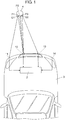
- FIG. 1 is a diagram for describing an operation of an object detection device according to an exemplary embodiment of the present disclosure.
- FIG. 2 is a diagram of vehicle 3 seen from the front side, and shows arrangement of reception units 11 to 14.
- FIG. 3 is a diagram of vehicle 3 seen from the left side, and shows the arrangement of reception units 11 to 14.
- the object detection device of the present exemplary embodiment has reception units 11 to 14, and a determination unit, disposed on the front side of vehicle 3.
- Each of reception units 11 to 14 outputs a voltage value corresponding to strength of an incident ultrasonic wave.
- Determination unit 2 determines presence or absence of object 4 which needs to be avoided (hereinafter, referred to as an "obstacle"), based on the outputs of reception units 11 to 14.
- object 4 to be determined as unnecessary to avoid is set to low-height object 4 to a degree capable of being driven over by vehicle 3, such as a low step, a road stud, or a curbstone, with a height of approximately 10 cm.
- Each of reception units 11 to 14 has a piezoelectric element (not shown), and a signal processing circuit (not shown).
- the signal processing circuit performs suitable signal processing, such as amplification or noise removal, by being interposed between the piezoelectric element and determination unit 2.
- the piezoelectric elements of reception units 11 to 14 are fixed by being arranged in a left-right direction on the front side of vehicle 3. Note that, while these piezoelectric elements are fixed on the front side in the present exemplary embodiment, the piezoelectric elements may be fixed on the rear side.
- Determination unit 2 determines the presence or absence of an obstacle in a prescribed detection range formed in front (or behind) vehicle 3.
- the left-right direction will be described based on FIG. 1 .
- the up-down direction of FIG. 1 is referred to as the front-rear direction of vehicle 3.
- the direction in which the surface that receives a reflected wave is facing, and in which the detection range is formed (upwards in FIG. 1 ), in reception units 11 to 14 is referred to as the front.
- Each of reception units 11 to 14 is disposed at a position higher than the height of object 4 capable of being driven over by vehicle 3 (that is, not considered as an obstacle).
- reception units 12 and 13 disposed in the center have a driving circuit for driving the piezoelectric element in accordance with a signal input from determination unit 2.
- Reception units 12 and 13 function as transmission units for transmitting a transmission wave to the detection range.
- reception units 12 and 13 are disposed at positions higher than reception units 11 and 14.
- the reception units capable of being used as transmission units are the reception units capable of being disposed in the center out of the three reception units for driving, specifically, reception unit 12 and reception unit 13.
- reception unit 12 and reception unit 13 only one reception unit is used at a time as a transmission unit. That is, only one of reception unit 12 and reception unit 13 is used at a time as a transmission unit.
- reception units 11 to 14 are used at a time. That is, when reception unit 12 is used as a transmission unit, reception unit 14 is not used, and reception units 11 to 13 are used, as reception units. On the other hand, when reception unit 13 is used as a transmission unit, reception unit 11 is not used, and reception units 12 to 14 are used as reception units.
- reception unit 12 when reception unit 12 is used as a transmission unit, the detection range is formed inclined more to the left than when reception unit 13 is used as a transmission unit.
- FIG. 1 shows an example where reception unit 12 is used as a transmission unit.
- Determination unit 2 has, for example, a storage unit (not shown) in which programs and data are stored, and a micro controller that operates in accordance with the programs stored in the storage unit. Determination unit 2 may be integrated in one chip. Moreover, a part of each of reception units 11 to 14 (for example, the signal processing circuit) may be integrated in one chip along with determination unit 2.
- reception units 11 to 13 are used as reception units.
- Determination unit 2 controls reception unit 12 so as to periodically transmit pulse-type transmission waves (ultrasonic waves).
- the duration of a transmission wave is shortened to the extent that reverberations in reception unit 12 are sufficiently attenuated before a reflected wave is received from the closest distance estimated from when transmission has started.
- the transmission interval of the transmission waves is longer than the time until a reflected wave is received from an estimated longest distance, and is as short as possible.
- determination unit 2 compares an output voltage with a prescribed reception threshold, and sets a timing at which the output voltage is equal to or higher than the reception threshold as a reception timing at which a reflected wave has been received. Note that, since reverberations are generated directly after the transmission of a transmission wave in reception unit 12, which is also utilized as a transmission unit, the output of reception unit 12 is ignored until a time has elapsed to the extent that the reverberations have sufficiently attenuated after the transmission of a transmission wave. In addition, for each of reception units 11 to 13, determination unit 2 measures a time from an immediate timing at which a transmission wave has been transmitted until the above reception timing (hereinafter, referred to as a "reception time").
- a sum of the distance from a point P1 at which the received reflected wave has been reflected (hereinafter, referred to as a "reflection point") to the transmission unit (that is, reception unit 12) and the distance from reception unit 11 that receives the reflected wave to reflection point P1 is obtained.
- a sum of the distance from reflection point P2 to the transmission unit and the distance from reception unit 12 that receives the reflected wave to reflection point P2 is obtained, and a sum of the distance from reflection point P3 to the transmission unit (that is, reception unit 12) and the distance from reception unit 13 that receives the reflected wave to reflection point P3 is obtained.
- reception unit 12 is also utilized as a transmission unit, the above ellipsoidal surface will have a distance between focal points that is 0 (that is, a spherical surface) for reception unit 12.
- determination unit 2 calculates, as coordinates Q1, coordinates of a point further on the front side with respect to reception unit 12, out of the intersection of an ellipsoidal surface obtained from the reception time in reception unit 11 (hereinafter, referred to as a "first reception time"), a spherical surface obtained from the reception time in reception unit 12 (hereinafter, referred to as a "second reception time”), and a horizontal surface that includes reception unit 12.
- first reception time an ellipsoidal surface obtained from the reception time in reception unit 11
- second reception time a spherical surface obtained from the reception time in reception unit 12
- determination unit 2 calculates, as coordinates Q2, coordinates of a point further on the front side with respect to reception unit 12, out of the intersection of a spherical surface obtained from the second reception time, an ellipsoidal surface obtained from the reception time in reception unit 13 (hereinafter, referred to as a "third reception time"), and a horizontal surface that includes reception unit 12.
- coordinates Q1 are at a position (coordinates) of reflection point P1 (P2), under the assumption that reflection point P1 that reflects a reflected wave received by reception unit 11 and reflection point P2 that reflects a reflected wave received by reception unit 12 are the same, and this reflection point P1 (P2) is located on a same horizontal surface as reception unit 12.
- coordinates Q2 are at a position (coordinates) of reflection point P2 (P3), under the assumption that second reflection point P2 and reflection point P3 that reflects a reflected wave received by reception unit 13 are the same, and this reflection point is located on a same horizontal surface as reception unit 12. Therefore, if the above assumptions are correct, coordinates Q1, coordinates Q2, and the positions of all of reflection points P1 to P3 coincide with one another, that is, the distance between coordinates Q1 and coordinates Q2 becomes 0.
- the distance between coordinates Q1. and coordinates Q2 increases. That is, in the case where the height of object 4 is lower than the height of reception units 11 to 13, the distance between coordinates Q1 and coordinates Q2 increases more than that in the case where the height of object 4 is higher than the height of reception units 11 to 13.
- determination unit 2 compares the distance between coordinates Q1 and coordinates Q2 (hereinafter, referred to as a "determination distance") with a prescribed reference distance.
- determination unit 2 determines that object 4 is an obstacle (that is, object 4 needs to be avoided), such as the ball shown in FIG. 1 .
- determination unit 2 outputs a prescribed electric signal (hereinafter, referred to as a "detection signal") to the outside.
- the detection signal is used, for example, as warning, or a trigger of automatic emergency brakes.
- determination unit 2 determines that object 4 is not an obstacle, since object 4 has a height lower than the height of reception units 11 to 13 and can be driven over by vehicle 3.
- the occurrence of incorrect detections can be reduced without reducing the detection range.
- reception unit 11 and reception unit 13 are disposed at mutually different heights, as shown in FIG. 2 and FIG. 3 .
- the determination distance increases since the distance between first reflection point P1 and third reflection point P3 increases in the case of object 4 with a low height. Therefore, in the object detection device of the present exemplary embodiment, it is easier to determine that object 4 is not an obstacle. That is, the occurrence of incorrect detections, such as object 4 with a height capable of being driven over by vehicle 3 and not to be detected as an obstacle, being detected as an obstacle, can be reduced.
- reception unit 11 may be disposed at a position higher than reception unit 13.
- both reception unit 11 and reception unit 14 may be disposed at positions higher than reception unit 12 and reception unit 13.
- the object detection device of the present exemplary embodiment described with reference to FIG. 1 includes a transmission unit (reception unit 12) for transmitting a transmission wave to a detection range, reception unit 11 for receiving a reflected wave resulting from the reflection of the transmission wave transmitted from the transmission unit (reception unit 12) by object 4 within the detection range, reception unit 12 for receiving a reflected wave resulting from the reflection of the transmission wave transmitted from the transmission unit (reception unit 12) by object 4 within the detection range, and reception unit 13 for receiving a reflected wave resulting from the reflection of the transmission wave transmitted from the transmission unit (reception unit 12) by object 4 within the detection range.
- the object detection device further includes determination unit 2 for determining the presence or absence of object 4 to be avoided, based on outputs of reception unit 11, reception unit 12, and reception unit 13.
- determination unit 2 calculates first coordinates Q1 at which object 4 is estimated to be present, based on a first reception time from when the transmission unit (reception unit 12) transmits a transmission wave until a reflected wave is received by reception unit 11, and a second reception time from when the transmission unit (reception unit 12) transmits a transmission wave until a reflected wave is received by reception unit 12. Further, determination unit 2 calculates second coordinates Q2 at which object 4 is estimated to be present, based on the second reception time, and a third reception time from when the transmission unit transmits a transmission wave until a reflected wave is received by reception unit 13.
- determination unit 2 compares a distance between first coordinates Q1 and second coordinates Q2 with a prescribed reference distance, determines that object 4 needs to be avoided in the case where the distance between first coordinates Q1 and second coordinates Q2 is less than the reference distance, and determines that object 4 does not need to be avoided in the case where the distance between first coordinates Q1 and second coordinates Q2 is equal to or larger than the reference distance.
- reception unit 12 is used as a transmission unit.
- FIG. 4 is a diagram for describing the operation, in an object detection device according to an exemplary embodiment of the present disclosure, in the case where object 4 that reflects a transmission wave is a wall.
- Object 4 shown in FIG. 4 has a determination distance that is equal to or larger than the reference distance since a distance between reflection point P1 and reflection point P3 is large, even though object 4 has a high height and needs to be avoided.
- the strength of a reflected wave (a peak value of the output voltages of reception units 11 to 13) is increased more than that in the case of object 4 with a low height that can be driven over by vehicle 3.
- determination unit 2 compares the peak value of the output voltage of each of reception units 11 to 13 (the strength of a reflected wave) with a reference threshold.
- object 4 is determined to be an obstacle if the peak value of the output voltages of all of reception units 11 to 13 is equal to or higher than the reference threshold, even if the determination distance is equal to or larger than the reference distance.
- determination unit 2 determines that object 4 is not an obstacle, in the case where the determination distance is equal to or larger than the reference distance, and the peak value of the output voltage in any one of reception units 11 to 13 is less than the reference threshold.
- the above reference threshold is the value at which the strength of a reflected wave (a peak value of the output voltages of reception units 11 to 13) in object (obstacle) 4 to be avoided is estimated to exceed, and is set higher than a reception threshold used for determination of a reception timing.
- the strength of a reflected wave in object 4 with a height lower than the height of reception units 11 to 13 decreases as the distance with object 4 increases, if the distance with object 4 is equal to or larger than a certain distance.
- the strength decreases as the distance with object 4 decreases, if the distance with object 4 is equal to or smaller than a certain distance, due to the directivity of each of reception units 11 to 13. Accordingly, determination unit 2 changes the reference threshold in accordance with the distance with object 4.
- determination unit 2 derives the reference threshold by using at least one of the first reception time, the second reception time, and the third reception time.
- a table may be used, or a computation may be used, for the derivation of the reference threshold. If the above configuration is adopted, detection omissions can be reduced, in which object 4 such as a wall is determined as not an obstacle.
- determination unit 2 derives a reference threshold at which the strength of a reflected wave in object 4 to be avoided is estimated to exceed, by using at least one of the first reception time, the second reception time, and the third reception time.
- determination unit 2 determines that object 4 needs to be avoided in the case where the strength of a reflected wave received by reception unit 11, the strength of a reflected wave received by reception unit 12, and the strength of a reflected wave received by reception unit 13 are all equal to or higher than the reference threshold.
- determination unit 2 calculates third coordinates Q3 by using the time from when the transmission wave is transmitted until a timing when an nth reflected wave (n is a prescribed integer of 2 or more) is received by third reception unit 13 (that is, a timing when a number of times the output voltage of reception unit 13 once falls below the reception threshold and again exceeds a reception threshold becomes n-1 times) (hereinafter, referred to as a "fourth reception time"), and the second reception time.
- the calculation of third coordinates Q3 is performed similarly to the calculation of second coordinates Q2, except that the fourth reception time is used instead of the third reception time.
- determination unit 2 calculates a distance between first coordinates Q1 and third coordinates Q3 (hereinafter, referred to as a "second determination distance"), and determines that object 4 needs to be avoided (that is, object 4 is an obstacle) if the second determination distance is less than the reference distance, even if the determination distance is equal to or larger than the reference distance. If the above configuration is adopted, detection omissions can be reduced, such as determining that object 4 does not need to be avoided (that is, object 4 is not an obstacle) due to increase in the determination distance in the case where a plurality of objects 4 are present or the like.
- determination unit 2 calculates third coordinates Q3 at which object 4 is estimated to be present, based on the second reception time, and a fourth reception time from when the transmission unit (reception unit 12) transmits a transmission wave until a prescribed number of 2 times or more of reflected waves are received by reception unit 13. Additionally, determination unit 2 determines that object 4 needs to be avoided, in the case where a distance between third coordinates Q3 and first coordinates Q1 is less than the reference distance, even in the case where a distance between first coordinates Q1 and second coordinates Q2 is equal to or larger than the reference distance.
- reception unit 13 is used as a transmission unit
- the operation is an operation common to the above description except that reception unit 12 is used instead of reception unit 11 in the above description and that reception unit 14 is used instead of reception unit 13 in the above description, and thus a description will be omitted.
- the object detection device of the present disclosure can reduce the occurrence of incorrect detections without reducing the detection range.
Landscapes
- Engineering & Computer Science (AREA)
- Radar, Positioning & Navigation (AREA)
- Remote Sensing (AREA)
- Physics & Mathematics (AREA)
- General Physics & Mathematics (AREA)
- Computer Networks & Wireless Communication (AREA)
- Acoustics & Sound (AREA)
- Mechanical Engineering (AREA)
- Measurement Of Velocity Or Position Using Acoustic Or Ultrasonic Waves (AREA)
- Traffic Control Systems (AREA)
Abstract
Description
- The present disclosure relates to an object detection device.
- A conventional object detection device is mounted in a vehicle, and detects an object by transmitting a transmission wave to a detection range and receiving a reflected wave resulting from the reflection by the object within the detection range. The above object detection device is used for an automatic control such as automatically applying brakes, for example, when an object has been detected.
- For example, it may not be necessary to avoid collision against an object low in height, such as a curbstone, which can be driven over by a vehicle. Accordingly, in order to avoid incorrect detections such as detection of the low-height object, an object detection device mounted in a vehicle is designed so that low objects to a certain degree are not included within a detection range (for example, PTL 1). Specifically, the transmission direction of a transmission wave is set to a horizontal direction, and when the vehicle body is inclined and there is a possibility that a low-height object as mentioned above is included within the detection range, the detection range is reduced by decreasing the gain of the reception of a reflected wave.
- PTL 1: Unexamined Japanese Patent Publication No.
2000-346936 - An object detection device according to the present disclosure includes a transmission unit for transmitting a transmission wave to a detection range, a first reception unit for receiving a reflected wave resulting from reflection of the transmission wave transmitted from the transmission unit by an object within the detection range, a second reception unit for receiving a reflected wave resulting from reflection of the transmission wave transmitted from the transmission unit by the object within the detection range, and a third reception unit for receiving a reflected wave resulting from the reflection of the transmission wave transmitted from the transmission unit by the object within the detection range. The object detection device further includes a determination unit for determining presence or absence of an object to be avoided, based on outputs of the first reception unit, the second reception unit, and the third reception unit.
- The determination unit calculates first coordinates at which the object is estimated to be present, based on a first reception time from when the transmission unit transmits a transmission wave until a reflected wave is received by the first reception unit, and a second reception time from when the transmission unit transmits a transmission wave until a reflected wave is received by the second reception unit, and calculates second coordinates at which the object is estimated to be present, based on the second reception time, and a third reception time from when the transmission unit transmits a transmission wave until a reflected wave is received by the third reception unit.
- Further, the determination unit compares a distance between the first coordinates and the second coordinates with a prescribed reference distance, determines that the object needs to be avoided in a case where the distance between the first coordinates and the second coordinates is less than the reference distance, and determines that an object is not the object to be avoided in a case where the distance between the first coordinates and the second coordinates is equal to or larger than the reference distance.
-
-
FIG. 1 is a diagram for describing an operation of an object detection device according to an exemplary embodiment. -
FIG. 2 is a diagram for describing arrangement of the object detection device according to the exemplary embodiment. -
FIG. 3 is a diagram for describing the arrangement of the object detection device according to the exemplary embodiment. -
FIG. 4 is a diagram for describing an operation of the object detection device according to the exemplary embodiment. -
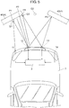
FIG. 5 is a diagram for describing an operation of the object detection device according to the exemplary embodiment. - Prior to description of the present exemplary embodiment, the problem of the above-mentioned conventional technique will be described.
- In the conventional object detection device, the distance by which an object can be detected (hereinafter, referred to as a "detection distance") is shortened when the detection range is reduced.
- An object of the present disclosure is to provide an object detection device that can suppress reduction of the detection distance, while reducing occurrence of incorrect detections.
- Hereinafter, the preferred embodiment of the present disclosure will be described with reference to the drawings.
- First, a case where an object that reflects a transmission wave output from the object detection device of the present exemplary embodiment is a ball, will be described with reference to the drawings.
-
FIG. 1 is a diagram for describing an operation of an object detection device according to an exemplary embodiment of the present disclosure.FIG. 2 is a diagram ofvehicle 3 seen from the front side, and shows arrangement ofreception units 11 to 14.FIG. 3 is a diagram ofvehicle 3 seen from the left side, and shows the arrangement ofreception units 11 to 14. - As shown in
FIG. 1 , the object detection device of the present exemplary embodiment hasreception units 11 to 14, and a determination unit, disposed on the front side ofvehicle 3. Each ofreception units 11 to 14 outputs a voltage value corresponding to strength of an incident ultrasonic wave.Determination unit 2 determines presence or absence ofobject 4 which needs to be avoided (hereinafter, referred to as an "obstacle"), based on the outputs ofreception units 11 to 14. Note that, in the present exemplary embodiment,object 4 to be determined as unnecessary to avoid (that is, not an obstacle) is set to low-height object 4 to a degree capable of being driven over byvehicle 3, such as a low step, a road stud, or a curbstone, with a height of approximately 10 cm. - Each of
reception units 11 to 14 has a piezoelectric element (not shown), and a signal processing circuit (not shown). The signal processing circuit performs suitable signal processing, such as amplification or noise removal, by being interposed between the piezoelectric element anddetermination unit 2. - The piezoelectric elements of
reception units 11 to 14 are fixed by being arranged in a left-right direction on the front side ofvehicle 3. Note that, while these piezoelectric elements are fixed on the front side in the present exemplary embodiment, the piezoelectric elements may be fixed on the rear side.Determination unit 2 determines the presence or absence of an obstacle in a prescribed detection range formed in front (or behind)vehicle 3. Hereinafter, the left-right direction will be described based onFIG. 1 . Moreover, the up-down direction ofFIG. 1 is referred to as the front-rear direction ofvehicle 3. The direction in which the surface that receives a reflected wave is facing, and in which the detection range is formed (upwards inFIG. 1 ), inreception units 11 to 14 is referred to as the front. - Each of
reception units 11 to 14 is disposed at a position higher than the height ofobject 4 capable of being driven over by vehicle 3 (that is, not considered as an obstacle). - Moreover, out of
reception units 11 to 14,reception units determination unit 2.Reception units - Moreover, as shown in
FIG. 2 and FIG. 3 ,reception units reception units - In the present exemplary embodiment, the reception units capable of being used as transmission units are the reception units capable of being disposed in the center out of the three reception units for driving, specifically,
reception unit 12 andreception unit 13. However, only one reception unit is used at a time as a transmission unit. That is, only one ofreception unit 12 andreception unit 13 is used at a time as a transmission unit. - Moreover, only three of
reception units 11 to 14 are used at a time. That is, whenreception unit 12 is used as a transmission unit,reception unit 14 is not used, andreception units 11 to 13 are used, as reception units. On the other hand, whenreception unit 13 is used as a transmission unit,reception unit 11 is not used, andreception units 12 to 14 are used as reception units. - Note that, when
reception unit 12 is used as a transmission unit, the detection range is formed inclined more to the left than whenreception unit 13 is used as a transmission unit. - Note that,
FIG. 1 shows an example wherereception unit 12 is used as a transmission unit. -
Determination unit 2 has, for example, a storage unit (not shown) in which programs and data are stored, and a micro controller that operates in accordance with the programs stored in the storage unit.Determination unit 2 may be integrated in one chip. Moreover, a part of each ofreception units 11 to 14 (for example, the signal processing circuit) may be integrated in one chip along withdetermination unit 2. - Next, the operation of
determination unit 2, in the case wherereception unit 12 is used as a transmission unit, will be described. At this time,reception units 11 to 13 are used as reception units. -
Determination unit 2 controlsreception unit 12 so as to periodically transmit pulse-type transmission waves (ultrasonic waves). The duration of a transmission wave is shortened to the extent that reverberations inreception unit 12 are sufficiently attenuated before a reflected wave is received from the closest distance estimated from when transmission has started. Moreover, the transmission interval of the transmission waves is longer than the time until a reflected wave is received from an estimated longest distance, and is as short as possible. - Moreover, for each of
reception units 11 to 13,determination unit 2 compares an output voltage with a prescribed reception threshold, and sets a timing at which the output voltage is equal to or higher than the reception threshold as a reception timing at which a reflected wave has been received. Note that, since reverberations are generated directly after the transmission of a transmission wave inreception unit 12, which is also utilized as a transmission unit, the output ofreception unit 12 is ignored until a time has elapsed to the extent that the reverberations have sufficiently attenuated after the transmission of a transmission wave. In addition, for each ofreception units 11 to 13,determination unit 2 measures a time from an immediate timing at which a transmission wave has been transmitted until the above reception timing (hereinafter, referred to as a "reception time"). By multiplying the speed of sound by the reception time, a sum of the distance from a point P1 at which the received reflected wave has been reflected (hereinafter, referred to as a "reflection point") to the transmission unit (that is, reception unit 12) and the distance fromreception unit 11 that receives the reflected wave to reflection point P1 is obtained. Similarly, a sum of the distance from reflection point P2 to the transmission unit and the distance fromreception unit 12 that receives the reflected wave to reflection point P2 is obtained, and a sum of the distance from reflection point P3 to the transmission unit (that is, reception unit 12) and the distance fromreception unit 13 that receives the reflected wave to reflection point P3 is obtained. - That is, there are obtained ellipsoidal surfaces at which objects (reflection points P1 to P3) are estimated to be present. Since
reception unit 12 is also utilized as a transmission unit, the above ellipsoidal surface will have a distance between focal points that is 0 (that is, a spherical surface) forreception unit 12. - In the case where a reflected wave has been received by each of
reception units 11 to 13,determination unit 2 calculates, as coordinates Q1, coordinates of a point further on the front side with respect toreception unit 12, out of the intersection of an ellipsoidal surface obtained from the reception time in reception unit 11 (hereinafter, referred to as a "first reception time"), a spherical surface obtained from the reception time in reception unit 12 (hereinafter, referred to as a "second reception time"), and a horizontal surface that includesreception unit 12. Moreover,determination unit 2 calculates, as coordinates Q2, coordinates of a point further on the front side with respect toreception unit 12, out of the intersection of a spherical surface obtained from the second reception time, an ellipsoidal surface obtained from the reception time in reception unit 13 (hereinafter, referred to as a "third reception time"), and a horizontal surface that includesreception unit 12. - Incidentally, coordinates Q1 are at a position (coordinates) of reflection point P1 (P2), under the assumption that reflection point P1 that reflects a reflected wave received by
reception unit 11 and reflection point P2 that reflects a reflected wave received byreception unit 12 are the same, and this reflection point P1 (P2) is located on a same horizontal surface asreception unit 12. Similarly, coordinates Q2 are at a position (coordinates) of reflection point P2 (P3), under the assumption that second reflection point P2 and reflection point P3 that reflects a reflected wave received byreception unit 13 are the same, and this reflection point is located on a same horizontal surface asreception unit 12. Therefore, if the above assumptions are correct, coordinates Q1, coordinates Q2, and the positions of all of reflection points P1 to P3 coincide with one another, that is, the distance between coordinates Q1 and coordinates Q2 becomes 0. - Inversely, as the deviation from the above assumption increases, that is, as the distance between reflection point P1 and reflection point P3 increases, or as each of reflection points P1 to P3 moves away from
reception unit 12 in an up-down direction (height direction), the distance between coordinates Q1. and coordinates Q2 increases. That is, in the case where the height ofobject 4 is lower than the height ofreception units 11 to 13, the distance between coordinates Q1 and coordinates Q2 increases more than that in the case where the height ofobject 4 is higher than the height ofreception units 11 to 13. - Accordingly,
determination unit 2 compares the distance between coordinates Q1 and coordinates Q2 (hereinafter, referred to as a "determination distance") with a prescribed reference distance. - If the determination distance is less than the reference distance,
determination unit 2 determines thatobject 4 is an obstacle (that is,object 4 needs to be avoided), such as the ball shown inFIG. 1 . When it is determined thatobject 4 needs to be avoided,determination unit 2 outputs a prescribed electric signal (hereinafter, referred to as a "detection signal") to the outside. The detection signal is used, for example, as warning, or a trigger of automatic emergency brakes. - If the determination distance is equal to or larger than the reference distance,
determination unit 2 determines thatobject 4 is not an obstacle, sinceobject 4 has a height lower than the height ofreception units 11 to 13 and can be driven over byvehicle 3. - According to the above configuration, by determining the presence or absence of an obstacle (whether or not the obstacle needs to be avoided) based on the determination distance, incorrect detections can be reduced, such as determining that
object 4 needs to be avoided even thoughobject 4 that reflects a transmission wave has a low height and does not need to be avoided. - Moreover, in the conventional object detection device, while low-
height object 4 being incorrectly detected as an obstacle is avoided by reducing the detection range, in the present exemplary embodiment, as compared to a conventional object detection device, the occurrence of incorrect detections can be reduced without reducing the detection range. - Moreover, in the present exemplary embodiment,
reception unit 11 andreception unit 13 are disposed at mutually different heights, as shown inFIG. 2 and FIG. 3 . As a result, compared to the case wherereception unit 11 andreception unit 13 are located at the same height (that is, on a same horizontal surface), the determination distance increases since the distance between first reflection point P1 and third reflection point P3 increases in the case ofobject 4 with a low height. Therefore, in the object detection device of the present exemplary embodiment, it is easier to determine thatobject 4 is not an obstacle. That is, the occurrence of incorrect detections, such asobject 4 with a height capable of being driven over byvehicle 3 and not to be detected as an obstacle, being detected as an obstacle, can be reduced. Note that, whilereception unit 11 is disposed at a position lower thanreception unit 13 inFIG. 2 and FIG. 3 ,reception unit 11 may be disposed at a position higher thanreception unit 13. In this case, in the case wherereception units 11 to 14 needs to be arranged symmetrical in a left-right direction due to design or the like, bothreception unit 11 andreception unit 14 may be disposed at positions higher thanreception unit 12 andreception unit 13. - That is, the object detection device of the present exemplary embodiment described with reference to
FIG. 1 includes a transmission unit (reception unit 12) for transmitting a transmission wave to a detection range,reception unit 11 for receiving a reflected wave resulting from the reflection of the transmission wave transmitted from the transmission unit (reception unit 12) byobject 4 within the detection range,reception unit 12 for receiving a reflected wave resulting from the reflection of the transmission wave transmitted from the transmission unit (reception unit 12) byobject 4 within the detection range, andreception unit 13 for receiving a reflected wave resulting from the reflection of the transmission wave transmitted from the transmission unit (reception unit 12) byobject 4 within the detection range. The object detection device further includesdetermination unit 2 for determining the presence or absence ofobject 4 to be avoided, based on outputs ofreception unit 11,reception unit 12, andreception unit 13. - Also,
determination unit 2 calculates first coordinates Q1 at which object 4 is estimated to be present, based on a first reception time from when the transmission unit (reception unit 12) transmits a transmission wave until a reflected wave is received byreception unit 11, and a second reception time from when the transmission unit (reception unit 12) transmits a transmission wave until a reflected wave is received byreception unit 12. Further,determination unit 2 calculates second coordinates Q2 at which object 4 is estimated to be present, based on the second reception time, and a third reception time from when the transmission unit transmits a transmission wave until a reflected wave is received byreception unit 13. - Further,
determination unit 2 compares a distance between first coordinates Q1 and second coordinates Q2 with a prescribed reference distance, determines thatobject 4 needs to be avoided in the case where the distance between first coordinates Q1 and second coordinates Q2 is less than the reference distance, and determines thatobject 4 does not need to be avoided in the case where the distance between first coordinates Q1 and second coordinates Q2 is equal to or larger than the reference distance. - Note that, in the present exemplary embodiment,
reception unit 12 is used as a transmission unit. - Next, a case where an object that reflects a transmission wave output from the object detection device of the present exemplary embodiment is wide (that is, large in the left-right direction)
object 4 such as a wall, will be described with reference toFIG. 4 . -
FIG. 4 is a diagram for describing the operation, in an object detection device according to an exemplary embodiment of the present disclosure, in the case whereobject 4 that reflects a transmission wave is a wall. -
Object 4 shown inFIG. 4 has a determination distance that is equal to or larger than the reference distance since a distance between reflection point P1 and reflection point P3 is large, even thoughobject 4 has a high height and needs to be avoided. However, in the above case, the strength of a reflected wave (a peak value of the output voltages ofreception units 11 to 13) is increased more than that in the case ofobject 4 with a low height that can be driven over byvehicle 3. Accordingly, in order to reduce detection omissions where it is determined thatobject 4 such as the wall is not an obstacle,determination unit 2 compares the peak value of the output voltage of each ofreception units 11 to 13 (the strength of a reflected wave) with a reference threshold. Also,object 4 is determined to be an obstacle if the peak value of the output voltages of all ofreception units 11 to 13 is equal to or higher than the reference threshold, even if the determination distance is equal to or larger than the reference distance. In other words,determination unit 2 determines thatobject 4 is not an obstacle, in the case where the determination distance is equal to or larger than the reference distance, and the peak value of the output voltage in any one ofreception units 11 to 13 is less than the reference threshold. The above reference threshold is the value at which the strength of a reflected wave (a peak value of the output voltages ofreception units 11 to 13) in object (obstacle) 4 to be avoided is estimated to exceed, and is set higher than a reception threshold used for determination of a reception timing. Moreover, the strength of a reflected wave inobject 4 with a height lower than the height ofreception units 11 to 13 decreases as the distance withobject 4 increases, if the distance withobject 4 is equal to or larger than a certain distance. However, the strength decreases as the distance withobject 4 decreases, if the distance withobject 4 is equal to or smaller than a certain distance, due to the directivity of each ofreception units 11 to 13. Accordingly,determination unit 2 changes the reference threshold in accordance with the distance withobject 4. - Specifically,
determination unit 2 derives the reference threshold by using at least one of the first reception time, the second reception time, and the third reception time. A table may be used, or a computation may be used, for the derivation of the reference threshold. If the above configuration is adopted, detection omissions can be reduced, in which object 4 such as a wall is determined as not an obstacle. - That is, in the object detection device of the present exemplary embodiment, more preferably,
determination unit 2 derives a reference threshold at which the strength of a reflected wave inobject 4 to be avoided is estimated to exceed, by using at least one of the first reception time, the second reception time, and the third reception time. - In addition, even if the distance between first coordinates Q1 and second coordinates Q2 is equal to or larger than the reference distance,
determination unit 2 determines thatobject 4 needs to be avoided in the case where the strength of a reflected wave received byreception unit 11, the strength of a reflected wave received byreception unit 12, and the strength of a reflected wave received byreception unit 13 are all equal to or higher than the reference threshold. - Moreover, as a case where the determination distance is equal to or larger than the reference distance even though
object 4 is an obstacle, a case can be considered whereobject 4A having first reflection point P1 and object 4B having third reflection point P3 are separated from each other and there is a space between first reflection point P1 and third reflection point P3 as shown inFIG. 5 . In such a case, since the strength of a reflected wave decreases, it cannot be determined as low-height object 4, even if the reference threshold as mentioned above is used. However, in such a case, reflected waves are received a plurality of times by each ofreception units 11 to 13 for one transmission wave. Accordingly,determination unit 2 calculates third coordinates Q3 by using the time from when the transmission wave is transmitted until a timing when an nth reflected wave (n is a prescribed integer of 2 or more) is received by third reception unit 13 (that is, a timing when a number of times the output voltage ofreception unit 13 once falls below the reception threshold and again exceeds a reception threshold becomes n-1 times) (hereinafter, referred to as a "fourth reception time"), and the second reception time. The calculation of third coordinates Q3 is performed similarly to the calculation of second coordinates Q2, except that the fourth reception time is used instead of the third reception time. In addition,determination unit 2 calculates a distance between first coordinates Q1 and third coordinates Q3 (hereinafter, referred to as a "second determination distance"), and determines thatobject 4 needs to be avoided (that is,object 4 is an obstacle) if the second determination distance is less than the reference distance, even if the determination distance is equal to or larger than the reference distance. If the above configuration is adopted, detection omissions can be reduced, such as determining thatobject 4 does not need to be avoided (that is,object 4 is not an obstacle) due to increase in the determination distance in the case where a plurality ofobjects 4 are present or the like. - That is, in the object detection device of the present exemplary embodiment, more preferably,
determination unit 2 calculates third coordinates Q3 at which object 4 is estimated to be present, based on the second reception time, and a fourth reception time from when the transmission unit (reception unit 12) transmits a transmission wave until a prescribed number of 2 times or more of reflected waves are received byreception unit 13. Additionally,determination unit 2 determines thatobject 4 needs to be avoided, in the case where a distance between third coordinates Q3 and first coordinates Q1 is less than the reference distance, even in the case where a distance between first coordinates Q1 and second coordinates Q2 is equal to or larger than the reference distance. - Next, a case where
object 4 that reflects a transmission wave output from the object detection device of the present exemplary embodiment is separated into two, will be described with reference toFIG. 5 . - Moreover, as already described above, in the present exemplary embodiment, an operation for using
reception unit 13 as a transmission unit is also possible. In the case wherereception unit 13 is used as a transmission unit, the operation is an operation common to the above description except thatreception unit 12 is used instead ofreception unit 11 in the above description and thatreception unit 14 is used instead ofreception unit 13 in the above description, and thus a description will be omitted. - As is clear from the above description, according to the object detection device of the present disclosure, the occurrence of incorrect detections can be reduced, such as determining that an object needs to be avoided even though the object that reflects a transmission wave has a low height and does not need to be avoided. Moreover, as compared to a conventional object detection device that reduces the occurrence of incorrect detections of an object as described above by reducing the detection range, the object detection device of the present disclosure can reduce the occurrence of incorrect detections without reducing the detection range.
-
- 2
- determination unit
- 4, 4A, 4B
- object
- 11, 12, 13, 14
- reception unit
- Q1, Q2, Q3
- coordinates
Claims (5)
- An object detection device comprising:a transmission unit for transmitting a transmission wave to a detection range;a first reception unit for receiving a reflected wave resulting from reflection of the transmission wave transmitted from the transmission unit by an object within the detection range;a second reception unit for receiving a reflected wave resulting from reflection of the transmission wave transmitted from the transmission unit by an object within the detection range;a third reception unit for receiving a reflected wave resulting from reflection of the transmission wave transmitted from the transmission unit by an object within the detection range; anda determination unit for determining presence or absence of an object to be avoided, based on outputs of the first reception unit, the second reception unit, and the third reception unit,wherein the determination unitcalculates first coordinates at which an object is estimated to be present, based on a first reception time from when the transmission unit transmits a transmission wave until a reflected wave is received by the first reception unit, and a second reception time from when the transmission unit transmits a transmission wave until a reflected wave is received by the second reception unit,calculates second coordinates at which an object is estimated to be present, based on the second reception time, and a third reception time from when the transmission unit transmits a transmission wave until a reflected wave is received by the third reception unit, andcompares a distance between the first coordinates and the second coordinates with a prescribed reference distance, determines that an object is the object to be avoided in a case where the distance between the first coordinates and the second coordinates is less than the reference distance, and determines that an object is not the object to be avoided in a case where the distance between the first coordinates and the second coordinates is equal to or larger than the reference distance.
- The object detection device according to claim 1, wherein the second reception unit is used as the transmission unit.
- The object detection device according to claim 1 or 2, wherein
the determination unit
calculates third coordinates at which an object is estimated to be present, based on the second reception time, and a fourth reception time from when the transmission unit transmits a transmission wave until a prescribed number of two times or more of reflected waves are received by the third reception unit,
and determines that an object is the object to be avoided in a case where a distance between the third coordinates and the first coordinates is less than the reference distance, even in the case where the distance between the first coordinates and the second coordinates is equal to or larger than the reference distance. - The object detection device according to any one of claims 1 to 3, wherein
the determination unit derives a reference threshold at which a strength of a reflected wave in an object to be avoided is estimated to exceed, by using at least one of the first reception time, the second reception time, and the third reception time, and
the determination unit determines that an object is the object to be avoided, in a case where a strength of a reflected wave received by the first reception unit, a strength of a reflected wave received by the second reception unit, and a strength of a reflected wave received by the third reception unit are all equal to or higher than the reference threshold, even in the case where the distance between the first coordinates and the second coordinates is equal to or larger than the reference distance. - The object detection device according to any one of claims 1 to 4, wherein the first reception unit and the third reception unit are disposed at mutually different heights.
Applications Claiming Priority (2)
| Application Number | Priority Date | Filing Date | Title |
|---|---|---|---|
| JP2014205012A JP6403055B2 (en) | 2014-10-03 | 2014-10-03 | Object detection device |
| PCT/JP2015/004998 WO2016051805A1 (en) | 2014-10-03 | 2015-10-01 | Object detection device |
Publications (3)
| Publication Number | Publication Date |
|---|---|
| EP3203261A1 true EP3203261A1 (en) | 2017-08-09 |
| EP3203261A4 EP3203261A4 (en) | 2017-10-25 |
| EP3203261B1 EP3203261B1 (en) | 2018-09-12 |
Family
ID=55629867
Family Applications (1)
| Application Number | Title | Priority Date | Filing Date |
|---|---|---|---|
| EP15846981.7A Active EP3203261B1 (en) | 2014-10-03 | 2015-10-01 | Object detection device |
Country Status (4)
| Country | Link |
|---|---|
| US (1) | US10295666B2 (en) |
| EP (1) | EP3203261B1 (en) |
| JP (1) | JP6403055B2 (en) |
| WO (1) | WO2016051805A1 (en) |
Families Citing this family (4)
| Publication number | Priority date | Publication date | Assignee | Title |
|---|---|---|---|---|
| JP6577767B2 (en) * | 2015-06-30 | 2019-09-18 | 株式会社デンソー | Object detection apparatus and object detection method |
| CN110214098B (en) * | 2017-02-09 | 2021-09-17 | 本田技研工业株式会社 | Mounting structure of external environment detection device for vehicle |
| JP6750567B2 (en) * | 2017-05-30 | 2020-09-02 | 株式会社Soken | Object detection device |
| JP6820132B2 (en) * | 2018-09-05 | 2021-01-27 | 三菱電機株式会社 | Driving support device |
Family Cites Families (11)
| Publication number | Priority date | Publication date | Assignee | Title |
|---|---|---|---|---|
| JPH0792265A (en) * | 1993-09-20 | 1995-04-07 | Sumitomo Electric Ind Ltd | Obstacle detection device |
| US5574426A (en) * | 1995-06-30 | 1996-11-12 | Insys, Ltd. | Obstacle detection system for vehicles moving in reverse |
| JP3788109B2 (en) | 1999-06-07 | 2006-06-21 | 日産自動車株式会社 | Obstacle detection device |
| US8194132B2 (en) * | 2006-01-20 | 2012-06-05 | Old World Industries, Llc | System for monitoring an area adjacent a vehicle |
| JP5444589B2 (en) * | 2006-06-30 | 2014-03-19 | アイシン精機株式会社 | Information processing apparatus, information processing method, and program |
| DE102008021614B4 (en) * | 2008-01-14 | 2015-09-24 | Siemens Aktiengesellschaft | A method, apparatus, node and computer program for determining a position of a node in an ad hoc network |
| JP4799631B2 (en) * | 2009-02-27 | 2011-10-26 | 株式会社日本自動車部品総合研究所 | Object detection device |
| DE102010030466B4 (en) * | 2010-06-24 | 2021-05-20 | Robert Bosch Gmbh | Procedure for warning a driver of a collision |
| KR101976391B1 (en) * | 2012-11-16 | 2019-08-28 | 현대모비스 주식회사 | Vehicle Parking Assist Apparatus and Method |
| CN104755344B (en) * | 2012-11-27 | 2016-05-04 | 日产自动车株式会社 | Vehicle acceleration suppressing device and vehicle acceleration suppressing method |
| JP6369035B2 (en) * | 2013-02-05 | 2018-08-08 | 株式会社デンソー | Target detection device |
-
2014
- 2014-10-03 JP JP2014205012A patent/JP6403055B2/en not_active Expired - Fee Related
-
2015
- 2015-10-01 US US15/509,584 patent/US10295666B2/en active Active
- 2015-10-01 EP EP15846981.7A patent/EP3203261B1/en active Active
- 2015-10-01 WO PCT/JP2015/004998 patent/WO2016051805A1/en not_active Ceased
Also Published As
| Publication number | Publication date |
|---|---|
| US20170285168A1 (en) | 2017-10-05 |
| JP6403055B2 (en) | 2018-10-10 |
| EP3203261B1 (en) | 2018-09-12 |
| JP2016075526A (en) | 2016-05-12 |
| EP3203261A4 (en) | 2017-10-25 |
| WO2016051805A1 (en) | 2016-04-07 |
| US10295666B2 (en) | 2019-05-21 |
Similar Documents
| Publication | Publication Date | Title |
|---|---|---|
| US11726203B2 (en) | Object detection device | |
| EP3203261B1 (en) | Object detection device | |
| US10745008B2 (en) | Driving support device and driving support method | |
| US9830818B2 (en) | Parking zone recognizing apparatus and control method thereof | |
| KR102310278B1 (en) | System and method for the vehicle autonomous emergency braking | |
| US9815442B2 (en) | Advanced emergency brake system and method for controlling brake thereof | |
| US8823578B2 (en) | Driving assist apparatus | |
| JP6432423B2 (en) | Object detection apparatus and object detection method | |
| WO2017104773A1 (en) | Moving body control device and moving body control method | |
| US11603096B2 (en) | Traveling control apparatus | |
| WO2017110702A1 (en) | Driving-assistance device and driving-assistance method | |
| US20190212444A1 (en) | Detection device, detection method, and recording medium | |
| WO2016204213A1 (en) | Vehicle control device and vehicle control method | |
| US9908525B2 (en) | Travel control apparatus | |
| US11163061B2 (en) | Object detection apparatus and object detection method | |
| JP2014099019A (en) | Collision prevention apparatus for vehicle | |
| US9582886B2 (en) | Object recognition device | |
| CN106662642A (en) | Detection system | |
| US9714033B2 (en) | Vehicle collision avoidance system | |
| US10914832B2 (en) | Estimation apparatus | |
| EP4369035A1 (en) | Object detection device | |
| US20240427016A1 (en) | Obstacle detection device, obstacle detection method, and computer-readable medium | |
| US20190256063A1 (en) | Deceleration determination device and non-transitory computer readable storage medium for storing program thereof | |
| CN112166344B (en) | Detection device | |
| CN114167428B (en) | Object detection device |
Legal Events
| Date | Code | Title | Description |
|---|---|---|---|
| PUAI | Public reference made under article 153(3) epc to a published international application that has entered the european phase |
Free format text: ORIGINAL CODE: 0009012 |
|
| 17P | Request for examination filed |
Effective date: 20170209 |
|
| AK | Designated contracting states |
Kind code of ref document: A1 Designated state(s): AL AT BE BG CH CY CZ DE DK EE ES FI FR GB GR HR HU IE IS IT LI LT LU LV MC MK MT NL NO PL PT RO RS SE SI SK SM TR |
|
| AX | Request for extension of the european patent |
Extension state: BA ME |
|
| A4 | Supplementary search report drawn up and despatched |
Effective date: 20170922 |
|
| RIC1 | Information provided on ipc code assigned before grant |
Ipc: G08G 1/16 20060101ALI20170918BHEP Ipc: G01S 15/87 20060101ALI20170918BHEP Ipc: B60R 21/00 20060101ALI20170918BHEP Ipc: G01S 5/22 20060101ALI20170918BHEP Ipc: G01S 15/93 20060101AFI20170918BHEP |
|
| DAV | Request for validation of the european patent (deleted) | ||
| DAX | Request for extension of the european patent (deleted) | ||
| GRAJ | Information related to disapproval of communication of intention to grant by the applicant or resumption of examination proceedings by the epo deleted |
Free format text: ORIGINAL CODE: EPIDOSDIGR1 |
|
| GRAP | Despatch of communication of intention to grant a patent |
Free format text: ORIGINAL CODE: EPIDOSNIGR1 |
|
| INTG | Intention to grant announced |
Effective date: 20180326 |
|
| RIN1 | Information on inventor provided before grant (corrected) |
Inventor name: NAKAGAWA, TAKUMA |
|
| GRAS | Grant fee paid |
Free format text: ORIGINAL CODE: EPIDOSNIGR3 |
|
| GRAA | (expected) grant |
Free format text: ORIGINAL CODE: 0009210 |
|
| AK | Designated contracting states |
Kind code of ref document: B1 Designated state(s): AL AT BE BG CH CY CZ DE DK EE ES FI FR GB GR HR HU IE IS IT LI LT LU LV MC MK MT NL NO PL PT RO RS SE SI SK SM TR |
|
| REG | Reference to a national code |
Ref country code: GB Ref legal event code: FG4D |
|
| REG | Reference to a national code |
Ref country code: CH Ref legal event code: EP |
|
| REG | Reference to a national code |
Ref country code: IE Ref legal event code: FG4D |
|
| REG | Reference to a national code |
Ref country code: DE Ref legal event code: R096 Ref document number: 602015016381 Country of ref document: DE |
|
| REG | Reference to a national code |
Ref country code: AT Ref legal event code: REF Ref document number: 1041275 Country of ref document: AT Kind code of ref document: T Effective date: 20181015 |
|
| REG | Reference to a national code |
Ref country code: NL Ref legal event code: MP Effective date: 20180912 |
|
| REG | Reference to a national code |
Ref country code: LT Ref legal event code: MG4D |
|
| PG25 | Lapsed in a contracting state [announced via postgrant information from national office to epo] |
Ref country code: RS Free format text: LAPSE BECAUSE OF FAILURE TO SUBMIT A TRANSLATION OF THE DESCRIPTION OR TO PAY THE FEE WITHIN THE PRESCRIBED TIME-LIMIT Effective date: 20180912 Ref country code: LT Free format text: LAPSE BECAUSE OF FAILURE TO SUBMIT A TRANSLATION OF THE DESCRIPTION OR TO PAY THE FEE WITHIN THE PRESCRIBED TIME-LIMIT Effective date: 20180912 Ref country code: BG Free format text: LAPSE BECAUSE OF FAILURE TO SUBMIT A TRANSLATION OF THE DESCRIPTION OR TO PAY THE FEE WITHIN THE PRESCRIBED TIME-LIMIT Effective date: 20181212 Ref country code: SE Free format text: LAPSE BECAUSE OF FAILURE TO SUBMIT A TRANSLATION OF THE DESCRIPTION OR TO PAY THE FEE WITHIN THE PRESCRIBED TIME-LIMIT Effective date: 20180912 Ref country code: FI Free format text: LAPSE BECAUSE OF FAILURE TO SUBMIT A TRANSLATION OF THE DESCRIPTION OR TO PAY THE FEE WITHIN THE PRESCRIBED TIME-LIMIT Effective date: 20180912 Ref country code: GR Free format text: LAPSE BECAUSE OF FAILURE TO SUBMIT A TRANSLATION OF THE DESCRIPTION OR TO PAY THE FEE WITHIN THE PRESCRIBED TIME-LIMIT Effective date: 20181213 Ref country code: NO Free format text: LAPSE BECAUSE OF FAILURE TO SUBMIT A TRANSLATION OF THE DESCRIPTION OR TO PAY THE FEE WITHIN THE PRESCRIBED TIME-LIMIT Effective date: 20181212 |
|
| PG25 | Lapsed in a contracting state [announced via postgrant information from national office to epo] |
Ref country code: HR Free format text: LAPSE BECAUSE OF FAILURE TO SUBMIT A TRANSLATION OF THE DESCRIPTION OR TO PAY THE FEE WITHIN THE PRESCRIBED TIME-LIMIT Effective date: 20180912 Ref country code: LV Free format text: LAPSE BECAUSE OF FAILURE TO SUBMIT A TRANSLATION OF THE DESCRIPTION OR TO PAY THE FEE WITHIN THE PRESCRIBED TIME-LIMIT Effective date: 20180912 Ref country code: AL Free format text: LAPSE BECAUSE OF FAILURE TO SUBMIT A TRANSLATION OF THE DESCRIPTION OR TO PAY THE FEE WITHIN THE PRESCRIBED TIME-LIMIT Effective date: 20180912 |
|
| REG | Reference to a national code |
Ref country code: AT Ref legal event code: MK05 Ref document number: 1041275 Country of ref document: AT Kind code of ref document: T Effective date: 20180912 |
|
| REG | Reference to a national code |
Ref country code: DE Ref legal event code: R084 Ref document number: 602015016381 Country of ref document: DE |
|
| PG25 | Lapsed in a contracting state [announced via postgrant information from national office to epo] |
Ref country code: IS Free format text: LAPSE BECAUSE OF FAILURE TO SUBMIT A TRANSLATION OF THE DESCRIPTION OR TO PAY THE FEE WITHIN THE PRESCRIBED TIME-LIMIT Effective date: 20190112 Ref country code: AT Free format text: LAPSE BECAUSE OF FAILURE TO SUBMIT A TRANSLATION OF THE DESCRIPTION OR TO PAY THE FEE WITHIN THE PRESCRIBED TIME-LIMIT Effective date: 20180912 Ref country code: ES Free format text: LAPSE BECAUSE OF FAILURE TO SUBMIT A TRANSLATION OF THE DESCRIPTION OR TO PAY THE FEE WITHIN THE PRESCRIBED TIME-LIMIT Effective date: 20180912 Ref country code: NL Free format text: LAPSE BECAUSE OF FAILURE TO SUBMIT A TRANSLATION OF THE DESCRIPTION OR TO PAY THE FEE WITHIN THE PRESCRIBED TIME-LIMIT Effective date: 20180912 Ref country code: EE Free format text: LAPSE BECAUSE OF FAILURE TO SUBMIT A TRANSLATION OF THE DESCRIPTION OR TO PAY THE FEE WITHIN THE PRESCRIBED TIME-LIMIT Effective date: 20180912 Ref country code: RO Free format text: LAPSE BECAUSE OF FAILURE TO SUBMIT A TRANSLATION OF THE DESCRIPTION OR TO PAY THE FEE WITHIN THE PRESCRIBED TIME-LIMIT Effective date: 20180912 Ref country code: IT Free format text: LAPSE BECAUSE OF FAILURE TO SUBMIT A TRANSLATION OF THE DESCRIPTION OR TO PAY THE FEE WITHIN THE PRESCRIBED TIME-LIMIT Effective date: 20180912 Ref country code: CZ Free format text: LAPSE BECAUSE OF FAILURE TO SUBMIT A TRANSLATION OF THE DESCRIPTION OR TO PAY THE FEE WITHIN THE PRESCRIBED TIME-LIMIT Effective date: 20180912 Ref country code: PL Free format text: LAPSE BECAUSE OF FAILURE TO SUBMIT A TRANSLATION OF THE DESCRIPTION OR TO PAY THE FEE WITHIN THE PRESCRIBED TIME-LIMIT Effective date: 20180912 |
|
| PG25 | Lapsed in a contracting state [announced via postgrant information from national office to epo] |
Ref country code: SM Free format text: LAPSE BECAUSE OF FAILURE TO SUBMIT A TRANSLATION OF THE DESCRIPTION OR TO PAY THE FEE WITHIN THE PRESCRIBED TIME-LIMIT Effective date: 20180912 Ref country code: SK Free format text: LAPSE BECAUSE OF FAILURE TO SUBMIT A TRANSLATION OF THE DESCRIPTION OR TO PAY THE FEE WITHIN THE PRESCRIBED TIME-LIMIT Effective date: 20180912 Ref country code: PT Free format text: LAPSE BECAUSE OF FAILURE TO SUBMIT A TRANSLATION OF THE DESCRIPTION OR TO PAY THE FEE WITHIN THE PRESCRIBED TIME-LIMIT Effective date: 20190112 |
|
| REG | Reference to a national code |
Ref country code: CH Ref legal event code: PL |
|
| REG | Reference to a national code |
Ref country code: DE Ref legal event code: R097 Ref document number: 602015016381 Country of ref document: DE |
|
| REG | Reference to a national code |
Ref country code: BE Ref legal event code: MM Effective date: 20181031 |
|
| PG25 | Lapsed in a contracting state [announced via postgrant information from national office to epo] |
Ref country code: LU Free format text: LAPSE BECAUSE OF NON-PAYMENT OF DUE FEES Effective date: 20181001 |
|
| PLBE | No opposition filed within time limit |
Free format text: ORIGINAL CODE: 0009261 |
|
| STAA | Information on the status of an ep patent application or granted ep patent |
Free format text: STATUS: NO OPPOSITION FILED WITHIN TIME LIMIT |
|
| REG | Reference to a national code |
Ref country code: IE Ref legal event code: MM4A |
|
| PG25 | Lapsed in a contracting state [announced via postgrant information from national office to epo] |
Ref country code: DK Free format text: LAPSE BECAUSE OF FAILURE TO SUBMIT A TRANSLATION OF THE DESCRIPTION OR TO PAY THE FEE WITHIN THE PRESCRIBED TIME-LIMIT Effective date: 20180912 Ref country code: MC Free format text: LAPSE BECAUSE OF FAILURE TO SUBMIT A TRANSLATION OF THE DESCRIPTION OR TO PAY THE FEE WITHIN THE PRESCRIBED TIME-LIMIT Effective date: 20180912 |
|
| 26N | No opposition filed |
Effective date: 20190613 |
|
| PG25 | Lapsed in a contracting state [announced via postgrant information from national office to epo] |
Ref country code: SI Free format text: LAPSE BECAUSE OF FAILURE TO SUBMIT A TRANSLATION OF THE DESCRIPTION OR TO PAY THE FEE WITHIN THE PRESCRIBED TIME-LIMIT Effective date: 20180912 Ref country code: BE Free format text: LAPSE BECAUSE OF NON-PAYMENT OF DUE FEES Effective date: 20181031 Ref country code: LI Free format text: LAPSE BECAUSE OF NON-PAYMENT OF DUE FEES Effective date: 20181031 Ref country code: CH Free format text: LAPSE BECAUSE OF NON-PAYMENT OF DUE FEES Effective date: 20181031 |
|
| PG25 | Lapsed in a contracting state [announced via postgrant information from national office to epo] |
Ref country code: IE Free format text: LAPSE BECAUSE OF NON-PAYMENT OF DUE FEES Effective date: 20181001 Ref country code: FR Free format text: LAPSE BECAUSE OF NON-PAYMENT OF DUE FEES Effective date: 20181112 |
|
| PG25 | Lapsed in a contracting state [announced via postgrant information from national office to epo] |
Ref country code: MT Free format text: LAPSE BECAUSE OF NON-PAYMENT OF DUE FEES Effective date: 20181001 |
|
| PG25 | Lapsed in a contracting state [announced via postgrant information from national office to epo] |
Ref country code: TR Free format text: LAPSE BECAUSE OF FAILURE TO SUBMIT A TRANSLATION OF THE DESCRIPTION OR TO PAY THE FEE WITHIN THE PRESCRIBED TIME-LIMIT Effective date: 20180912 |
|
| PG25 | Lapsed in a contracting state [announced via postgrant information from national office to epo] |
Ref country code: HU Free format text: LAPSE BECAUSE OF FAILURE TO SUBMIT A TRANSLATION OF THE DESCRIPTION OR TO PAY THE FEE WITHIN THE PRESCRIBED TIME-LIMIT; INVALID AB INITIO Effective date: 20151001 Ref country code: CY Free format text: LAPSE BECAUSE OF FAILURE TO SUBMIT A TRANSLATION OF THE DESCRIPTION OR TO PAY THE FEE WITHIN THE PRESCRIBED TIME-LIMIT Effective date: 20180912 Ref country code: MK Free format text: LAPSE BECAUSE OF NON-PAYMENT OF DUE FEES Effective date: 20180912 |
|
| GBPC | Gb: european patent ceased through non-payment of renewal fee |
Effective date: 20191001 |
|
| PG25 | Lapsed in a contracting state [announced via postgrant information from national office to epo] |
Ref country code: GB Free format text: LAPSE BECAUSE OF NON-PAYMENT OF DUE FEES Effective date: 20191001 |
|
| REG | Reference to a national code |
Ref country code: DE Ref legal event code: R081 Ref document number: 602015016381 Country of ref document: DE Owner name: PANASONIC AUTOMOTIVE SYSTEMS CO., LTD., YOKOHA, JP Free format text: FORMER OWNER: PANASONIC INTELLECTUAL PROPERTY MANAGEMENT CO., LTD, OSAKA-SHI, OSAKA, JP |
|
| PGFP | Annual fee paid to national office [announced via postgrant information from national office to epo] |
Ref country code: DE Payment date: 20251021 Year of fee payment: 11 |