EP3203179A1 - Measuring machine based on a delta robot assembly - Google Patents
Measuring machine based on a delta robot assembly Download PDFInfo
- Publication number
- EP3203179A1 EP3203179A1 EP16154393.9A EP16154393A EP3203179A1 EP 3203179 A1 EP3203179 A1 EP 3203179A1 EP 16154393 A EP16154393 A EP 16154393A EP 3203179 A1 EP3203179 A1 EP 3203179A1
- Authority
- EP
- European Patent Office
- Prior art keywords
- probe
- base plate
- measuring machine
- movable platform
- coordinate measuring
- Prior art date
- Legal status (The legal status is an assumption and is not a legal conclusion. Google has not performed a legal analysis and makes no representation as to the accuracy of the status listed.)
- Granted
Links
Images



Classifications
-
- G—PHYSICS
- G01—MEASURING; TESTING
- G01B—MEASURING LENGTH, THICKNESS OR SIMILAR LINEAR DIMENSIONS; MEASURING ANGLES; MEASURING AREAS; MEASURING IRREGULARITIES OF SURFACES OR CONTOURS
- G01B21/00—Measuring arrangements or details thereof, where the measuring technique is not covered by the other groups of this subclass, unspecified or not relevant
- G01B21/02—Measuring arrangements or details thereof, where the measuring technique is not covered by the other groups of this subclass, unspecified or not relevant for measuring length, width, or thickness
- G01B21/04—Measuring arrangements or details thereof, where the measuring technique is not covered by the other groups of this subclass, unspecified or not relevant for measuring length, width, or thickness by measuring coordinates of points
-
- B—PERFORMING OPERATIONS; TRANSPORTING
- B25—HAND TOOLS; PORTABLE POWER-DRIVEN TOOLS; MANIPULATORS
- B25J—MANIPULATORS; CHAMBERS PROVIDED WITH MANIPULATION DEVICES
- B25J9/00—Program-controlled manipulators
- B25J9/003—Program-controlled manipulators having parallel kinematics
- B25J9/0045—Program-controlled manipulators having parallel kinematics with kinematics chains having a rotary joint at the base
- B25J9/0051—Program-controlled manipulators having parallel kinematics with kinematics chains having a rotary joint at the base with kinematics chains of the type rotary-universal-universal or rotary-spherical-spherical, e.g. Delta type manipulators
-
- B—PERFORMING OPERATIONS; TRANSPORTING
- B25—HAND TOOLS; PORTABLE POWER-DRIVEN TOOLS; MANIPULATORS
- B25J—MANIPULATORS; CHAMBERS PROVIDED WITH MANIPULATION DEVICES
- B25J9/00—Program-controlled manipulators
- B25J9/003—Program-controlled manipulators having parallel kinematics
- B25J9/0063—Program-controlled manipulators having parallel kinematics with kinematics chains having an universal joint at the base
-
- F—MECHANICAL ENGINEERING; LIGHTING; HEATING; WEAPONS; BLASTING
- F21—LIGHTING
- F21V—FUNCTIONAL FEATURES OR DETAILS OF LIGHTING DEVICES OR SYSTEMS THEREOF; STRUCTURAL COMBINATIONS OF LIGHTING DEVICES WITH OTHER ARTICLES, NOT OTHERWISE PROVIDED FOR
- F21V21/00—Supporting, suspending, or attaching arrangements for lighting devices; Hand grips
- F21V21/14—Adjustable mountings
- F21V21/22—Adjustable mountings telescopic
-
- F—MECHANICAL ENGINEERING; LIGHTING; HEATING; WEAPONS; BLASTING
- F21—LIGHTING
- F21V—FUNCTIONAL FEATURES OR DETAILS OF LIGHTING DEVICES OR SYSTEMS THEREOF; STRUCTURAL COMBINATIONS OF LIGHTING DEVICES WITH OTHER ARTICLES, NOT OTHERWISE PROVIDED FOR
- F21V21/00—Supporting, suspending, or attaching arrangements for lighting devices; Hand grips
- F21V21/14—Adjustable mountings
- F21V21/26—Pivoted arms
-
- G—PHYSICS
- G01—MEASURING; TESTING
- G01B—MEASURING LENGTH, THICKNESS OR SIMILAR LINEAR DIMENSIONS; MEASURING ANGLES; MEASURING AREAS; MEASURING IRREGULARITIES OF SURFACES OR CONTOURS
- G01B11/00—Measuring arrangements characterised by the use of optical techniques
- G01B11/002—Measuring arrangements characterised by the use of optical techniques for measuring two or more coordinates
-
- G—PHYSICS
- G01—MEASURING; TESTING
- G01B—MEASURING LENGTH, THICKNESS OR SIMILAR LINEAR DIMENSIONS; MEASURING ANGLES; MEASURING AREAS; MEASURING IRREGULARITIES OF SURFACES OR CONTOURS
- G01B11/00—Measuring arrangements characterised by the use of optical techniques
- G01B11/002—Measuring arrangements characterised by the use of optical techniques for measuring two or more coordinates
- G01B11/005—Measuring arrangements characterised by the use of optical techniques for measuring two or more coordinates coordinate measuring machines
-
- G—PHYSICS
- G01—MEASURING; TESTING
- G01B—MEASURING LENGTH, THICKNESS OR SIMILAR LINEAR DIMENSIONS; MEASURING ANGLES; MEASURING AREAS; MEASURING IRREGULARITIES OF SURFACES OR CONTOURS
- G01B17/00—Measuring arrangements characterised by the use of infrasonic, sonic or ultrasonic vibrations
-
- G—PHYSICS
- G01—MEASURING; TESTING
- G01B—MEASURING LENGTH, THICKNESS OR SIMILAR LINEAR DIMENSIONS; MEASURING ANGLES; MEASURING AREAS; MEASURING IRREGULARITIES OF SURFACES OR CONTOURS
- G01B5/00—Measuring arrangements characterised by the use of mechanical techniques
- G01B5/0002—Arrangements for supporting, fixing or guiding the measuring instrument or the object to be measured
- G01B5/0004—Supports
-
- H—ELECTRICITY
- H04—ELECTRIC COMMUNICATION TECHNIQUE
- H04N—PICTORIAL COMMUNICATION, e.g. TELEVISION
- H04N23/00—Cameras or camera modules comprising electronic image sensors; Control thereof
- H04N23/50—Constructional details
- H04N23/54—Mounting of pick-up tubes, electronic image sensors, deviation or focusing coils
-
- H—ELECTRICITY
- H04—ELECTRIC COMMUNICATION TECHNIQUE
- H04N—PICTORIAL COMMUNICATION, e.g. TELEVISION
- H04N7/00—Television systems
- H04N7/18—Closed-circuit television [CCTV] systems, i.e. systems in which the video signal is not broadcast
- H04N7/181—Closed-circuit television [CCTV] systems, i.e. systems in which the video signal is not broadcast for receiving images from a plurality of remote sources
-
- G—PHYSICS
- G01—MEASURING; TESTING
- G01B—MEASURING LENGTH, THICKNESS OR SIMILAR LINEAR DIMENSIONS; MEASURING ANGLES; MEASURING AREAS; MEASURING IRREGULARITIES OF SURFACES OR CONTOURS
- G01B2210/00—Aspects not specifically covered by any group under G01B, e.g. of wheel alignment, caliper-like sensors
- G01B2210/54—Revolving an optical measuring instrument around a body
-
- G—PHYSICS
- G01—MEASURING; TESTING
- G01B—MEASURING LENGTH, THICKNESS OR SIMILAR LINEAR DIMENSIONS; MEASURING ANGLES; MEASURING AREAS; MEASURING IRREGULARITIES OF SURFACES OR CONTOURS
- G01B2210/00—Aspects not specifically covered by any group under G01B, e.g. of wheel alignment, caliper-like sensors
- G01B2210/58—Wireless transmission of information between a sensor or probe and a control or evaluation unit
-
- G—PHYSICS
- G05—CONTROLLING; REGULATING
- G05B—CONTROL OR REGULATING SYSTEMS IN GENERAL; FUNCTIONAL ELEMENTS OF SUCH SYSTEMS; MONITORING OR TESTING ARRANGEMENTS FOR SUCH SYSTEMS OR ELEMENTS
- G05B2219/00—Program-control systems
- G05B2219/30—Nc systems
- G05B2219/45—Nc applications
- G05B2219/45061—Measuring robot
Definitions
- the present invention relates to a measuring machine, in particular to a Coordinate Measuring Machine (CMM) or Vision Measuring Machine (VMM) based on a Delta Robot structure.
- CCM Coordinate Measuring Machine
- VMM Vision Measuring Machine
- a probe head In a conventional 3-D coordinate measurement machine a probe head is supported for movement along three mutually perpendicular axes (in directions X, Y and Z). Thereby, the probe head can be guided to any arbitrary point in a measuring volume of the CMM/VMM, and the object is measurable with a measurement sensor (probe) carried by the probe head.
- a measurement sensor probe
- ultrasonic probes For measuring surface variations, various measurement principles are known: one is based on the use of ultrasonic sensors/ultrasonic transducers (called ultrasonic probes), another one is based on the use of tactile sensors (also called tactile probes) and even another one is based on the use of optical sensors (also called optical probes or cameras).
- ultrasonic probes For gauging the surface of a target object the optical or tactile probe is movably fixed at an articulated arm, as it is shown for a tactile probe i.e. in EP 2283311 A1 , or at a portal, as it is shown for an optical probe i.e. in WO 2008/135530 A1 , so that it can be moved over the surface of the target object in the three Cartesian directions x, y, z.
- a further possibility to move a probe over a target object is mounting the probe movable in z direction and placing the target object on a table movable in x- and y-direction.
- Still a further possibility to move a probe over a target object is shown in brochure " Equator 300 Mess-Systeme" of Renishaw, published in July 2011 ; wherein a tactile probe is mounted on the movable carrier platform of a delta robot.
- the tactile probe of this measuring machine has to contact the surface of the target object, the possibilities that the delta structure provides with respect to acceleration and motion speed is not fully exploited.
- the vision measuring machine using an optical probe described in WO 2014/040937 which more likely is able to use the full measurement speed of the delta robot structure.
- the main advantage of the delta robot structure is that it is a light-weight construction, able to move very fast and also showing very high accelerations.
- the main disadvantage is however, similar as with a portal CMM or an articulated arm measuring machine the required volume of such a delta robot structure.
- a known CMM 10 using a delta robot structure 12 with a camera 22 as an optical probe 4 is given for acquisition of small scale 3D (3 dimensional) information, i.e. in the area of quality control of workpieces 50, wherein small scale is in the range of mm down to nm.
- the delta robot 12 comprises a static top supporting platform 14 fixed by an arrangement of horizontal levers 11 at a stationary side frame 13 with piles 13'.
- the piles 13' of the side frame 13 are protruding perpendicular from a frame table 15.
- Three middle jointed 26 arms 16, 16', 16" extending from the static top supporting platform 14.
- the arms 16, 16', 16" often called kinematic chains, are connected with their first end to the static top supporting platform 14 by means of first universal joints 24 and connected with their second end by means of third joints 28 to an end effector 18 supporting the probe 4.
- the end effector 18 is often built in form of a triangular or circular platform.
- the arms 16, 16', 16" are made of lightweight composite material and are driven by actuators (not shown) located in the static top supporting platform 14, controlled by a control unit 38.
- the control unit 38 can also be configured to serve as an analysing unit, but analysing of the data collected by the probe can also be analysed by an external computer like unit.
- the moving parts of the delta robot have a small inertia. This allows for very high accelerations and very fast movement, which outclasses by far those realizable by a portal machine or an articulated arm.
- delta robots are highly sensitive with respect to temperature fluctuation and to strong vibrations during fast movement and fast acceleration/deceleration actions, caused by their lightweight construction. For measurements of high accuracy, the localisation of the end effector determined by the angle encoders in the joints 24, 26, 28 is often not sufficient.
- CMM 10 with a delta robot structure has been developed with a global measuring system 30 provided with stationary cameras 32 watching one or more markings 20, positioned at the arms 16, 16', 16" and/or at the end effector 18, from different perspective so that a precise determination of the current location of the end effector 18 can be given at any time.
- degree of freedom (DOF) of the end effector 18 of a delta robot had been extended from pure translation (movement in parallelograms only with 3 degrees of freedom (3DOF: translation in the x- , y- or z-direction and vectors thereof)) up to 6DOF, additionally allowing the end effector 18 rotational movements of maximum about 360° around those axis resulting in yawing, rolling, pitching.
- the volume occupied by the delta robot 12 is considerable larger than the measuring volume, wherein the measuring volume is defined by the coverage of the movement of the end effector 18 with its probe 4; or with other words: the measuring volume is the volume, which can be covered by the movement of the end effector 18 with the probe 4.
- a delta robot structure usually needs space for the top static supporting platform 14 and for the frame 15, 13, 11 which holds the top static supporting platform 14. This frame 11, 13, 15 adds volume to the actual measuring volume and also reduces accessibility to the measuring volume.
- Object of the current invention is therefore to provide more compact measuring machine based on a delta structure.
- the present invention relates to a CMM based on a delta structure comprising a base plate, a movable platform, arms and a control unit.
- the arms having each a middle joint and are connected with their first end by means of first universal joints to the base plate. Further the arms are connected with their second end by means of third universal joints 28 to the movable platform, wherein the movable platform supports a probe for gauging a workpiece.
- the movement of the movable platform is controlled unit by the control unit, wherein the control unit optionally is configured to serve also as an analysing unit for analysing the data collected by the probe.
- the base plate is configured for accommodating a first workpiece to be gauged by the probe, wherein the probe is arranged in/at/on the movable platform in a way using the free inside space of the delta robot structure as measuring volume.
- the probe is at least one out of the group of probe types comprising: an ultrasonic probe, a tactile probe, an optical probe; wherein the probe is mounted on the movable platform in a way that the trajectory of the tactile probe and the path way of the ultrasonic waves of the ultrasonic probe and the field of view of an optical probe, respectively, are directed through the arms onto the base plate.
- the whole CMM is transportable and can i.e. be put on the floor, on a table or other supporting means, wherever it is needed.
- the base plate is mounted fixable to a frame table or is un-dissolvable fixed to a frame table or is formed as one piece with a frame table.
- the frame table is provided to serve as a supporting basis for additional equipment.
- the control unit is advantageously integrated in the base plate or - in case that there is a frame table alternatively in the frame table -, which is space saving.
- the control unit is configured to serve as analysing unit as well it is advantageous to provide the control and analysing unit as well as the probe with wireless communication means for a wireless data transfer, especially for the data collected by the probe to the control and analysing unit.
- wireless communication means for a wireless data transfer, especially for the data collected by the probe to the control and analysing unit.
- wire based embodiments are also suitable.
- the data collected by the probe are transferred to an external computer like unit for analysing, wherein this transfer can be wire based or wireless.
- At least one pile protrudes from the base plate or - in case there is a frame table - optionally from the frame table, in the same direction as the delta robot structure protrudes from the base plate.
- the at least one pile supports at least one lamp of a top illumination device, which lamp is preferably arranged pivotable around at least its horizontal axis, it might advantageously also pivotable around the axis of the pile, and is preferably laterally movable along the pile, wherein the lamp is fixable in the desired position.
- the at least one pile supports at least two stationary cameras of a global measuring system, wherein the at least two stationary cameras arranged preferably pivotable around at least its horizontal axis, it might advantageously also pivotable around the axis of the pile, and is preferably laterally movable along the pile, wherein the cameras are fixable in the desired position.
- the piles are adjustable in their longitudinal extension in a telescopic manner, which makes the CMM even more flexible.
- the piles are fixed connected to the base plate, preferably directly or by means of a frame table, in case there is a frame table.
- the piles are provided with heavy feet, so that they can be arranges flexible in number and position around the base plate, but stable in their position in relation to the base plate, because of the heavy foot.
- the CMM is provided with a global measuring system comprising at least two stationary cameras and a marking, i.e. at the movable platform and/or at the arms of the delta robot structure.
- the stationary cameras and the marking are arranged in a way that the marking is easily observable within the measuring volume by the stationary cameras, wherein the marking is preferably given in form of a chess pattern on the movable platform.
- the global measuring system increases accuracy of the measurement as it delivers additional data about the current position of the movable platform and the probe, addition to the information already given by the according meanings of the delta structure, i.e. delivered by angle encoders of the joints of the arms.
- the stationary cameras of the global measuring system are mounted directly at the frame table, preferably equally distributed.
- the marking is accordingly placed on the inside surface of the movable platform, wherein inside surface means the surface of the movable platform directed onto or facing the base plate and the measuring volume.
- stationary cameras of the global measuring system are mounted on cantilevers, which protrude radially from the base plate or from the frame table.
- stationary cameras of the global measuring system are mounted on piles (see above) in a level, so that they look onto the outside surface of the movable platform, where the marking is arranged, wherein the outside surface of the movable platform is directed away from the base plate.
- one has a first set of stationary cameras mounted on the side of the base plate and are configured to observe a first marking arranged at an inside surface of the movable platform and/or a marking at the arms of the delta robot structure, and an additional set of stationary cameras that is arranged on the piles configured to observe a second marking at the outside surface of the movable platform and/or a marking at the arms of the delta robot structure visible from their perspective.
- at least one of the base plate and the supporting plate are provided with fixation means, i.e. clamps, for fixing the first workpiece and/or second workpiece, respectively.
- the probe and the control unit are configured to measure simultaneously a first workpiece and a second workpiece by using an internal and an external measuring volume.
- Such a CMM allows a simultaneous measurement of two workpieces and is still very compact and space saving.
- the base plate and the supporting plate are provided with fixing means for fixation of a workpiece and the control unit is configured in a way that the measuring machine is usable with a randomly oriented base plate, so that the CMM is usable even more flexible.
- the probe is a single probe having two probe tips, one tip directed inwardly onto the base plate using the internal measuring volume and one tip directed outwardly onto the supporting plate using the external measuring volume, wherein the single probe collecting the data of both tips.
- the probe comprising a first probe and a second probe, wherein the first probe has a first tip directed inwardly onto the base plate using the internal measuring volume and collecting the data of the first tip and the second probe has a second tip directed outwardly onto the supporting plate using the external measuring volume collecting the data of the second tip, wherein the first probe and the second probe preferably the same type of probe, i.e. both probes are optical probes, tactile probes or ultrasonic probes.
- the robot arms advantageously directly support a safety light barriers.
- the measuring machine is further advantageously provided with an illumination device, wherein the illumination device is realized in form of a of a top illumination device comprising, i.e. a lamp on a pile (see above), and/or a back illumination device; wherein the back illumination device is preferably integrated in the base plate of the delta structure of the measuring machine, which base plate is therefore at least with respect to the part provided for supporting the workpiece made of a transparent material.
- the illumination device is realized in form of a of a top illumination device comprising, i.e. a lamp on a pile (see above), and/or a back illumination device; wherein the back illumination device is preferably integrated in the base plate of the delta structure of the measuring machine, which base plate is therefore at least with respect to the part provided for supporting the workpiece made of a transparent material.
- the illumination device is alternatively or in addition realized in form of a coaxial illumination device, wherein the illumination light is guided coaxially with the field of view of the optical sensor and especially through an objective of said optical sensor and/or in form of a ring illumination device arranged around an objective of the optical sensor.
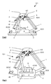
- Fig. 2 shows a measuring machine 10 with a delta robot structure 12 according to the invention.
- the delta robot structure 12 (also short delta structure 12) comprises a base plate 42, which base plate 42 supports a workpiece 50 during the measurement.
- the base plate 42 is located at the bottom of the structure in order to be placed on a floor or a table in a horizontal orientation.
- the base plate advantageously is provided with clamps (not shown) for a fixation of the workpiece 50.
- Three arms 16, 16', 16" of the delta robot structure 12 having middle joints 26, 26', 26" are connected with their first ends to the base plate 42 by first universal joints 24, 24', 24''.
- the arms 16, 16', 16" are connected with their opposite second ends to an end effector 18, also called movable platform 18, by means of third joints 28, 28', 28" and are controlled by a control and analysing unit 38 by means of actuators (not shown).
- the moving platform 18 carries a probe 4.
- the control and analysing unit 38 is - in this embodiment - arranged within the base plate 42.
- the control and analysing unit 38 and the probe 4 at the movable platform 18 are provided with a wireless connection for data exchange but could also be connected by wire connection provided in one of the arms 16, 16', 16''.
- the probe 4 is located using the free inside space of the delta robot structure as measuring volume, that means the probe 4 is mounted on the movable platform 18 in a way that an ultrasonic probe, a sensitive tip of the probe or the field of view of an optical sensor is directed through the arms 16, 16', 16" onto the base plate 42.
- this kind of measuring machine 10 could also be used in other orientations than with a bottom placed horizontal base plate 42, i.e. with the base plate 42 horizontal on the top and the movable platform 18 on the bottom.
- the base plate 42 than might be fixed, i.e. on a ceiling. It is also imaginable to fix the base plate 42 on a wall in a vertical orientation or on any other basis in a sloped orientation.
- the probe 4 of the measuring machine 10 can be any kind of probe usually used in an CMM (ultrasonic sensor, tactile sensor, optical sensor, etc.)
- the advantageous of the delta structure 12 high speed movement, fast acceleration and deceleration of the movable platform
- all embodiments of the measuring machine 10 given in figures 2 to 8 show an optical sensor 22 as a probe 4.
- a second embodiment of the measuring machine is given, which in principle is constructed in the same way as the one given in figure 2 .
- a global measuring system 30 is provided comprising three stationary cameras 32, 32', 32" arranged each laterally movable (double arrows) on a pile 34, 34', 34" and pivotable around its axis and fixable in the desired position.
- the three piles 34, 34', 34" have each a heavy foot 35, 35', 35", so that they are freely arrangeable around the delta robot structure 12 by the user, in order to be adapted in their position to the lighting conditions and their field of view in a way that allow them an easy observation of a marking 20, which in this case is given in form of a chess pattern on the outside 8 of the movable platform 18, wherein the outside 8 of the movable platform is the side directed outwardly, that means away from the arms 16, 16', 16" and away from the base plate 42.
- the field of view of the stationary cameras 32, 32', 32" is chosen in a way that the marking 20 is visible for the stationary cameras 32, 32', 32", or at least for two of them, for all movements of the movable platforms 18, or with other words the stationary cameras 32, 32', 32'' can observe the measuring volume.
- the measuring machine is provided with an own illumination device 40.
- the illumination device 40 is realized in form of a back illumination device 44 for illuminating the workpiece 50 from the back side.
- the back illumination device 44 is integrated in the base plate 42 of the delta structure 12 of the measuring machine 10, which base plate 42 is therefore at least with respect to the part supporting the workpiece 50 made of a transparent material.
- the embodiment of fig. 4 is very similar to that one in fig. 3 .
- the back illumination device 44 is subsidized in this embodiment by a top illumination device 39 comprising at least one, but in this embodiment actually three lamps 41, 41', 41", each arranged pivotable around its axis and laterally movable on a pile 34, 34', 34" of the global measuring system 30, so that the lamps 41, 41', 41" can be adjusted to illuminate the workpiece 50 in an optimized way.
- a person skilled in the art will realize that the back illumination device 44 shown in fig. 3 can be also combined with the top illumination device 39.
- a further difference is that the piles 34, 34', 34" and the base plate 42 with the arms 16, 16', 16" and the movable platform 18 are arranged in a fixed manner at a frame table 36, so that the delta robot structure 12, the illumination device 40 and the global measuring system 30 are arranged less flexible in relation to each other than in the embodiment of fig. 3 .
- the lack of flexibility is coupled with a more of accuracy and a less time consuming preparation.
- Figure 5 shows an even more compact embodiment of the measuring machine 10 based on a delta structure 12 having its probe 4 located is located using the free inside space of the delta robot structure 12 as measuring volume and provided with a global measuring system 30.
- the global measuring system 30 and the delta structure 12 are fixed on a frame table 36.
- the marking 20 in this sample is placed on the inside 9 of the movable platform 18.
- the stationary cameras 32, 32', 32" of the global measuring system 30 are mounted directly at the frame table 36- that means without any pile in-between. They are equally distributed on the frame table 36 in a way that they can easily survey the marking 20 on the inside 9 of the movable platform 18 when during the measurement the movable platform 18 with the probe 4 is moving in the measuring volume.
- this construction is more compact than the one given in figures 3 and 4 and it also allows an easier access to the measuring volume and base table 42 with the workpiece 50.
- the illumination device 40 is realized in form of a coaxial illumination 46, wherein the illumination light is guided coaxially with the field of view of the optical sensor 22 and especially through the objective of said optical sensor 22.
- this coaxial illumination is combinable with a back illumination device 43 and/or lamps 41, 41', 41" of a top illumination device 39 as they are shown in figures 3 and 4 .
- the embodiment given in figure 6 differs from that one shown in figure 5 by the illumination device 40, which is here realized by a ring illumination 48 arranged around an objective of the optical sensor 22 and a back light illumination device 44 integrated in the base plate 42.
- the illumination device 40 which is here realized by a ring illumination 48 arranged around an objective of the optical sensor 22 and a back light illumination device 44 integrated in the base plate 42.
- a further difference is, that there is no frame table, where the stationary cameras 32, 32', 32'' of the global measuring system 30 and the delta robot structure 12 with its base plate 42 is mounted on. Instead, the cameras 32, 32', 32" of the global measuring system 30 are mounted on cantilevers 49, 49', 49", which protrude advantageously radially from the base plate 42.
- the stationary overview cameras 32, 32', 32" of the global measuring system 30 are arranged beside or even below the supporting plane build by the base plate 42 for supporting the workpiece 50 in a way that they can easily survey the marking 20 on the inside 9 of the movable platform 18 during its movement within the measuring volume.
- this embodiment is even compacter and easily transportable.
- Figure 7 presents a further development of the measuring machine 10 according to the invention.
- the delta robot structure 12 is mounted via its base plate 42 on a frame table 36.
- the base plate 42 is provided with fixation means 43 for fixing the workpiece 50.
- Piles 34, 34', 34" protrude perpendicular from the frame table 36 in the same direction as the delta robot structure 12 similar as in figures 3 and 4 .
- the piles 34, 34', 34" support a supporting plate 54 which is arranged opposed to the base plate 42 and the frame table 36.
- the supporting plate 54 is provided with further fixation means 56, i.e. clamps, for an accurate fixation of a further workpiece 50'.
- the control and analysing unit is programmed to control the delta structure 12 in way that the movable platform 18 is moving in-between the base plate 42 and the supporting plate 54.
- the movable platform 18 in this embodiment is configured to carry two probes: a first probe 4 oriented with its sensor tip or field of view inwardly, that means between the arms 16, 16', 16" of the delta structure 12 onto the base plate 42, which base plate is provided for supporting the first workpiece 50 as it has been seen in the embodiments of figures 2 to 6 , and second probe 4' oriented with its sensor tip or field of view outwardly onto the supporting plate 54, which supporting plate 54 is provided for supporting the second workpiece 50'.
- the measuring machine 10 is configured to measure in a single measurement cycle two workpieces 50, 50' simultaneously using an internal and an external measuring volume.
- the cameras 32, 32', 32'' of the global measuring system 30 are arranged slightly laterally movable and pivotable around their own axis at the frame table 36 and observing a marking 20 on the inside 8 of the movable platform 18.
- the two probes 4, 4' are in particular optical sensors 22, 22' wherein either one optical sensor 22 is arranged at the inside 9 of the movable platform 18 and the other optical sensor 22' is arranged at the outside 8 of the movable platform 18 or there is provided only one optical sensor having a divided field of view, one oriented outwardly the other oriented inwardly.
- a person skilled in the art knows the equipment needed to realize such a divided field of view.
- the two probes 4, 4' can be other sensors usually used in a CMM like all of the known different types of optical sensors, different types of ultra sonic sensors and different types of tactile sensors. It would also be imaginable not to use two sensors of the same type but to use for the different orientations (inwardly/outwardly) two different types of probes, i.e. two different types of optical sensors or two different types of tactile sensors or two different types of ultrasonic sensors or one ultra sound and one optical sensor, one tactile sensor and one optical senor, one ultra sound sensor and one tactile sensor; etc.. But this would as a rule lead to a decrease of the measurement speed and would require probably a longer preparation and calibration time and a more complex software etc..
- the embodiment of figure 8 differs from the one in figure 7 by having an additional cameras 52, 52,' 52" in the global measuring system 30 arranged on the piles 34, 34', 34" according to the example given in figures 3 and 4 and an additional marking 20' at the outside of the movable platform watched by the additional cameras 52, 52', 52''.
- Further back light devices 44, 44' are integrated in the base plate 42 and the supporting top 54.
- the piles 34, 34', 34" that supporting the supporting top 54 are adjustable in their height in a telescopic manner, so that they can protrude the movable platform 18 in view of the measuring volume and its distance to the base plate 42 from an intermediate distance up to a most outwardly position of the movable platform 18.
Landscapes
- Physics & Mathematics (AREA)
- General Physics & Mathematics (AREA)
- Engineering & Computer Science (AREA)
- Robotics (AREA)
- Mechanical Engineering (AREA)
- General Engineering & Computer Science (AREA)
- Multimedia (AREA)
- Signal Processing (AREA)
- Length Measuring Devices With Unspecified Measuring Means (AREA)
- A Measuring Device Byusing Mechanical Method (AREA)
- Manipulator (AREA)
Abstract
Description
- The present invention relates to a measuring machine, in particular to a Coordinate Measuring Machine (CMM) or Vision Measuring Machine (VMM) based on a Delta Robot structure.
- In a conventional 3-D coordinate measurement machine a probe head is supported for movement along three mutually perpendicular axes (in directions X, Y and Z). Thereby, the probe head can be guided to any arbitrary point in a measuring volume of the CMM/VMM, and the object is measurable with a measurement sensor (probe) carried by the probe head.
- For measuring surface variations, various measurement principles are known: one is based on the use of ultrasonic sensors/ultrasonic transducers (called ultrasonic probes), another one is based on the use of tactile sensors (also called tactile probes) and even another one is based on the use of optical sensors (also called optical probes or cameras). For gauging the surface of a target object the optical or tactile probe is movably fixed at an articulated arm, as it is shown for a tactile probe i.e. in
EP 2283311 A1 , or at a portal, as it is shown for an optical probe i.e. inWO 2008/135530 A1 , so that it can be moved over the surface of the target object in the three Cartesian directions x, y, z. A further possibility to move a probe over a target object is mounting the probe movable in z direction and placing the target object on a table movable in x- and y-direction. Still a further possibility to move a probe over a target object is shown in brochure "Equator 300 Mess-Systeme" of Renishaw, published in July 2011; wherein a tactile probe is mounted on the movable carrier platform of a delta robot. However, as the tactile probe of this measuring machine has to contact the surface of the target object, the possibilities that the delta structure provides with respect to acceleration and motion speed is not fully exploited. Also based on a delta robot structure is the vision measuring machine using an optical probe described inWO 2014/040937 , which more likely is able to use the full measurement speed of the delta robot structure. - The main advantage of the delta robot structure is that it is a light-weight construction, able to move very fast and also showing very high accelerations. The main disadvantage is however, similar as with a portal CMM or an articulated arm measuring machine the required volume of such a delta robot structure. In
figure 1 a knownCMM 10 using adelta robot structure 12 with a camera 22 as anoptical probe 4 is given for acquisition of small scale 3D (3 dimensional) information, i.e. in the area of quality control ofworkpieces 50, wherein small scale is in the range of mm down to nm. As it can be seen, thedelta robot 12 comprises a static top supporting platform 14 fixed by an arrangement of horizontal levers 11 at a stationary side frame 13 with piles 13'. The piles 13' of the side frame 13 are protruding perpendicular from a frame table 15. Three middle jointed 26arms arms universal joints 24 and connected with their second end by means ofthird joints 28 to anend effector 18 supporting theprobe 4. Theend effector 18 is often built in form of a triangular or circular platform. Thearms control unit 38. Thecontrol unit 38 can also be configured to serve as an analysing unit, but analysing of the data collected by the probe can also be analysed by an external computer like unit. - As the
arms joints CMM 10 with a delta robot structure has been developed with a global measuring system 30 provided withstationary cameras 32 watching one or more markings 20, positioned at thearms end effector 18, from different perspective so that a precise determination of the current location of theend effector 18 can be given at any time. Nowadays the degree of freedom (DOF) of theend effector 18 of a delta robot had been extended from pure translation (movement in parallelograms only with 3 degrees of freedom (3DOF: translation in the x- , y- or z-direction and vectors thereof)) up to 6DOF, additionally allowing theend effector 18 rotational movements of maximum about 360° around those axis resulting in yawing, rolling, pitching. - As it can be seen from
figure 1 the volume occupied by thedelta robot 12 is considerable larger than the measuring volume, wherein the measuring volume is defined by the coverage of the movement of theend effector 18 with itsprobe 4; or with other words: the measuring volume is the volume, which can be covered by the movement of theend effector 18 with theprobe 4. In addition to the measuring volume a delta robot structure usually needs space for the top static supporting platform 14 and for the frame 15, 13, 11 which holds the top static supporting platform 14. This frame 11, 13, 15 adds volume to the actual measuring volume and also reduces accessibility to the measuring volume. - As in industrial environments utility space and used volume are important criteria, the efforts are directed to minimise the required utility space and the required volume.
- Object of the current invention is therefore to provide more compact measuring machine based on a delta structure.
- The present invention relates to a CMM based on a delta structure comprising a base plate, a movable platform, arms and a control unit. The arms having each a middle joint and are connected with their first end by means of first universal joints to the base plate. Further the arms are connected with their second end by means of third
universal joints 28 to the movable platform, wherein the movable platform supports a probe for gauging a workpiece. The movement of the movable platform is controlled unit by the control unit, wherein the control unit optionally is configured to serve also as an analysing unit for analysing the data collected by the probe. The base plate is configured for accommodating a first workpiece to be gauged by the probe, wherein the probe is arranged in/at/on the movable platform in a way using the free inside space of the delta robot structure as measuring volume. Having the base plate configured for accommodating a first workpiece and having the probe arranged in/at/on the movable platform in a way using the free inside space of the delta robot structure as measuring volume - that means the space between the arms with a perspective from the movable platform onto the base plate -, having such a construction makes a separate supporting table for supporting the workpiece superfluous, so that the CMM is very compact and the workpiece supported by the base plate is easily accessible. - The probe is at least one out of the group of probe types comprising: an ultrasonic probe, a tactile probe, an optical probe; wherein the probe is mounted on the movable platform in a way that the trajectory of the tactile probe and the path way of the ultrasonic waves of the ultrasonic probe and the field of view of an optical probe, respectively, are directed through the arms onto the base plate.
- Having only the delta structure with the base plate, the arms, the platform and the control unit, the whole CMM is transportable and can i.e. be put on the floor, on a table or other supporting means, wherever it is needed.
- Optionally the base plate is mounted fixable to a frame table or is un-dissolvable fixed to a frame table or is formed as one piece with a frame table. In such an embodiment the frame table is provided to serve as a supporting basis for additional equipment.
- The control unit is advantageously integrated in the base plate or - in case that there is a frame table alternatively in the frame table -, which is space saving. In case the control unit is configured to serve as analysing unit as well it is advantageous to provide the control and analysing unit as well as the probe with wireless communication means for a wireless data transfer, especially for the data collected by the probe to the control and analysing unit. However, wire based embodiments are also suitable. In another embodiment the data collected by the probe are transferred to an external computer like unit for analysing, wherein this transfer can be wire based or wireless.
- In a preferred embodiment at least one pile protrudes from the base plate or - in case there is a frame table - optionally from the frame table, in the same direction as the delta robot structure protrudes from the base plate. The at least one pile supports at least one lamp of a top illumination device, which lamp is preferably arranged pivotable around at least its horizontal axis, it might advantageously also pivotable around the axis of the pile, and is preferably laterally movable along the pile, wherein the lamp is fixable in the desired position. Alternatively or in addition the at least one pile supports at least two stationary cameras of a global measuring system, wherein the at least two stationary cameras arranged preferably pivotable around at least its horizontal axis, it might advantageously also pivotable around the axis of the pile, and is preferably laterally movable along the pile, wherein the cameras are fixable in the desired position. In a preferred embodiment there is at least one camera at each pile. In another embodiment there are at least one camera and one lamp at each pile. As it is easily recognisable such a construction of the CMM allows a very flexible use of the CMM.
- In a preferred embodiment the piles are adjustable in their longitudinal extension in a telescopic manner, which makes the CMM even more flexible.
- Alternatively or in addition the piles are fixed connected to the base plate, preferably directly or by means of a frame table, in case there is a frame table.
- In an alternative embodiment the piles are provided with heavy feet, so that they can be arranges flexible in number and position around the base plate, but stable in their position in relation to the base plate, because of the heavy foot.
- In a preferred embodiment the CMM is provided with a global measuring system comprising at least two stationary cameras and a marking, i.e. at the movable platform and/or at the arms of the delta robot structure. The stationary cameras and the marking are arranged in a way that the marking is easily observable within the measuring volume by the stationary cameras, wherein the marking is preferably given in form of a chess pattern on the movable platform. The global measuring system increases accuracy of the measurement as it delivers additional data about the current position of the movable platform and the probe, addition to the information already given by the according meanings of the delta structure, i.e. delivered by angle encoders of the joints of the arms.
- In one embodiment the stationary cameras of the global measuring system are mounted directly at the frame table, preferably equally distributed. The marking is accordingly placed on the inside surface of the movable platform, wherein inside surface means the surface of the movable platform directed onto or facing the base plate and the measuring volume. This type of global measuring system allows an easy access to the measuring volume and the workpiece.
- In an alternative version stationary cameras of the global measuring system are mounted on cantilevers, which protrude radially from the base plate or from the frame table.
- Alternatively or additionally stationary cameras of the global measuring system are mounted on piles (see above) in a level, so that they look onto the outside surface of the movable platform, where the marking is arranged, wherein the outside surface of the movable platform is directed away from the base plate.
- Thus, one has a first set of stationary cameras mounted on the side of the base plate and are configured to observe a first marking arranged at an inside surface of the movable platform and/or a marking at the arms of the delta robot structure, and an additional set of stationary cameras that is arranged on the piles configured to observe a second marking at the outside surface of the movable platform and/or a marking at the arms of the delta robot structure visible from their perspective.
- In a preferred embodiment there are at least three piles protruding from the base plate or a frame table in the same direction as the delta robot structure and support a supporting plate, which is arranged opposed to the base plate and is provided for accommodating a second workpiece. In such an embodiment at least one of the base plate and the supporting plate are provided with fixation means, i.e. clamps, for fixing the first workpiece and/or second workpiece, respectively. The probe and the control unit are configured to measure simultaneously a first workpiece and a second workpiece by using an internal and an external measuring volume. Such a CMM allows a simultaneous measurement of two workpieces and is still very compact and space saving.
- In a special embodiment the base plate and the supporting plate are provided with fixing means for fixation of a workpiece and the control unit is configured in a way that the measuring machine is usable with a randomly oriented base plate, so that the CMM is usable even more flexible.
- In a very cost saving version of such a CMM the probe is a single probe having two probe tips, one tip directed inwardly onto the base plate using the internal measuring volume and one tip directed outwardly onto the supporting plate using the external measuring volume, wherein the single probe collecting the data of both tips. Alternatively the probe comprising a first probe and a second probe, wherein the first probe has a first tip directed inwardly onto the base plate using the internal measuring volume and collecting the data of the first tip and the second probe has a second tip directed outwardly onto the supporting plate using the external measuring volume collecting the data of the second tip, wherein the first probe and the second probe preferably the same type of probe, i.e. both probes are optical probes, tactile probes or ultrasonic probes.
- In all of the described embodiments the robot arms advantageously directly support a safety light barriers.
- The measuring machine is further advantageously provided with an illumination device, wherein the illumination device is realized in form of a of a top illumination device comprising, i.e. a lamp on a pile (see above), and/or a back illumination device; wherein the back illumination device is preferably integrated in the base plate of the delta structure of the measuring machine, which base plate is therefore at least with respect to the part provided for supporting the workpiece made of a transparent material.
- In case the probe of the measuring machine is an optical probe, the illumination device is alternatively or in addition realized in form of a coaxial illumination device, wherein the illumination light is guided coaxially with the field of view of the optical sensor and especially through an objective of said optical sensor and/or in form of a ring illumination device arranged around an objective of the optical sensor.
- Further embodiments and advantageous details are given in the following description of exemplary embodiments and in the dependent claims.
- The measuring machine according to the invention are described in greater detail purely by way of example below on the basis of specific exemplary embodiments illustrated schematically in the drawings, further advantages of the invention also being discussed. Identical elements are identified by identical reference signs in the figures. In specific detail the figures show purely schematically:
- Fig.1
- a CMM based on a delta robot structure according to the state of the art;
- Fig.2
- a first embodiment of a CMM according to the invention;
- Figs. 3 to 8
- further embodiments of a CMM according to the invention.
-
Fig. 2 shows a measuringmachine 10 with adelta robot structure 12 according to the invention. The delta robot structure 12 (also short delta structure 12) comprises abase plate 42, whichbase plate 42 supports aworkpiece 50 during the measurement. In the presented embodiment thebase plate 42 is located at the bottom of the structure in order to be placed on a floor or a table in a horizontal orientation. For a higher accuracy the base plate advantageously is provided with clamps (not shown) for a fixation of theworkpiece 50. Threearms delta robot structure 12 havingmiddle joints base plate 42 by firstuniversal joints 24, 24', 24''. Thearms end effector 18, also calledmovable platform 18, by means ofthird joints unit 38 by means of actuators (not shown). The movingplatform 18 carries aprobe 4. The control and analysingunit 38 is - in this embodiment - arranged within thebase plate 42. For analysing the generated data the control and analysingunit 38 and theprobe 4 at themovable platform 18 are provided with a wireless connection for data exchange but could also be connected by wire connection provided in one of thearms 16, 16', 16''. According to the invention theprobe 4 is located using the free inside space of the delta robot structure as measuring volume, that means theprobe 4 is mounted on themovable platform 18 in a way that an ultrasonic probe, a sensitive tip of the probe or the field of view of an optical sensor is directed through thearms base plate 42. - It will be appreciated that, as the workpiece is usually clamped on the
base plate 42 for getting accurate measurements, this kind of measuringmachine 10 could also be used in other orientations than with a bottom placedhorizontal base plate 42, i.e. with thebase plate 42 horizontal on the top and themovable platform 18 on the bottom. Thebase plate 42 than might be fixed, i.e. on a ceiling. It is also imaginable to fix thebase plate 42 on a wall in a vertical orientation or on any other basis in a sloped orientation. - In spite of the fact that the
probe 4 of the measuringmachine 10 can be any kind of probe usually used in an CMM (ultrasonic sensor, tactile sensor, optical sensor, etc.), the advantageous of the delta structure 12 (high speed movement, fast acceleration and deceleration of the movable platform) can be exploited the best by using an optical sensor 22 asprobe 4. Therefore all embodiments of the measuringmachine 10 given infigures 2 to 8 show an optical sensor 22 as aprobe 4. - In
figure 3 a second embodiment of the measuring machine is given, which in principle is constructed in the same way as the one given infigure 2 . However, in order to allow a more accurate measurement a global measuring system 30 is provided comprising threestationary cameras pile piles heavy foot delta robot structure 12 by the user, in order to be adapted in their position to the lighting conditions and their field of view in a way that allow them an easy observation of a marking 20, which in this case is given in form of a chess pattern on theoutside 8 of themovable platform 18, wherein theoutside 8 of the movable platform is the side directed outwardly, that means away from thearms base plate 42. The field of view of thestationary cameras stationary cameras movable platforms 18, or with other words thestationary cameras 32, 32', 32'' can observe the measuring volume. Advantageously the measuring machine is provided with an own illumination device 40. In this embodiment the illumination device 40 is realized in form of a back illumination device 44 for illuminating the workpiece 50 from the back side. The back illumination device 44 is integrated in thebase plate 42 of thedelta structure 12 of the measuringmachine 10, whichbase plate 42 is therefore at least with respect to the part supporting theworkpiece 50 made of a transparent material. - The embodiment of
fig. 4 is very similar to that one infig. 3 . But the back illumination device 44 is subsidized in this embodiment by a top illumination device 39 comprising at least one, but in this embodiment actually threelamps pile lamps workpiece 50 in an optimized way. However, a person skilled in the art will realize that the back illumination device 44 shown infig. 3 can be also combined with the top illumination device 39. A further difference is that thepiles base plate 42 with thearms movable platform 18 are arranged in a fixed manner at a frame table 36, so that thedelta robot structure 12, the illumination device 40 and the global measuring system 30 are arranged less flexible in relation to each other than in the embodiment offig. 3 . However, the lack of flexibility is coupled with a more of accuracy and a less time consuming preparation. -
Figure 5 shows an even more compact embodiment of the measuringmachine 10 based on adelta structure 12 having itsprobe 4 located is located using the free inside space of thedelta robot structure 12 as measuring volume and provided with a global measuring system 30. As in the embodiment offigure 4 the global measuring system 30 and thedelta structure 12 are fixed on a frame table 36. But the marking 20 in this sample is placed on theinside 9 of themovable platform 18. Thestationary cameras inside 9 of themovable platform 18 when during the measurement themovable platform 18 with theprobe 4 is moving in the measuring volume. As it can be seen fromfigure 5 , this construction is more compact than the one given infigures 3 and 4 and it also allows an easier access to the measuring volume and base table 42 with theworkpiece 50. In this sample the illumination device 40 is realized in form of a coaxial illumination 46, wherein the illumination light is guided coaxially with the field of view of the optical sensor 22 and especially through the objective of said optical sensor 22. Of course this coaxial illumination is combinable with aback illumination device 43 and/orlamps figures 3 and 4 . - The embodiment given in
figure 6 differs from that one shown infigure 5 by the illumination device 40, which is here realized by a ring illumination 48 arranged around an objective of the optical sensor 22 and a back light illumination device 44 integrated in thebase plate 42. A further difference is, that there is no frame table, where thestationary cameras 32, 32', 32'' of the global measuring system 30 and thedelta robot structure 12 with itsbase plate 42 is mounted on. Instead, thecameras cantilevers base plate 42. As in the embodiment offigure 5 , thestationary overview cameras base plate 42 for supporting theworkpiece 50 in a way that they can easily survey the marking 20 on theinside 9 of themovable platform 18 during its movement within the measuring volume. Compared with the sample offigure 5 this embodiment is even compacter and easily transportable. -
Figure 7 presents a further development of the measuringmachine 10 according to the invention. As it can be seen thedelta robot structure 12 is mounted via itsbase plate 42 on a frame table 36. Thebase plate 42 is provided with fixation means 43 for fixing theworkpiece 50.Piles delta robot structure 12 similar as infigures 3 and 4 . But in this embodiment thepiles plate 54 which is arranged opposed to thebase plate 42 and the frame table 36. The supportingplate 54 is provided with further fixation means 56, i.e. clamps, for an accurate fixation of a further workpiece 50'. The control and analysing unit is programmed to control thedelta structure 12 in way that themovable platform 18 is moving in-between thebase plate 42 and the supportingplate 54. Themovable platform 18 in this embodiment is configured to carry two probes: afirst probe 4 oriented with its sensor tip or field of view inwardly, that means between thearms delta structure 12 onto thebase plate 42, which base plate is provided for supporting thefirst workpiece 50 as it has been seen in the embodiments offigures 2 to 6 , and second probe 4' oriented with its sensor tip or field of view outwardly onto the supportingplate 54, which supportingplate 54 is provided for supporting the second workpiece 50'. Being constructed this way the measuringmachine 10 is configured to measure in a single measurement cycle twoworkpieces 50, 50' simultaneously using an internal and an external measuring volume. - As known from the embodiment of
figure 5 thecameras 32, 32', 32'' of the global measuring system 30 are arranged slightly laterally movable and pivotable around their own axis at the frame table 36 and observing a marking 20 on theinside 8 of themovable platform 18. The twoprobes 4, 4' are in particular optical sensors 22, 22' wherein either one optical sensor 22 is arranged at theinside 9 of themovable platform 18 and the other optical sensor 22' is arranged at theoutside 8 of themovable platform 18 or there is provided only one optical sensor having a divided field of view, one oriented outwardly the other oriented inwardly. A person skilled in the art knows the equipment needed to realize such a divided field of view. - It will be appreciated that instead of optical sensors the two
probes 4, 4' can be other sensors usually used in a CMM like all of the known different types of optical sensors, different types of ultra sonic sensors and different types of tactile sensors. It would also be imaginable not to use two sensors of the same type but to use for the different orientations (inwardly/outwardly) two different types of probes, i.e. two different types of optical sensors or two different types of tactile sensors or two different types of ultrasonic sensors or one ultra sound and one optical sensor, one tactile sensor and one optical senor, one ultra sound sensor and one tactile sensor; etc.. But this would as a rule lead to a decrease of the measurement speed and would require probably a longer preparation and calibration time and a more complex software etc.. - The embodiment of
figure 8 differs from the one infigure 7 by having an additional cameras 52, 52,' 52" in the global measuring system 30 arranged on thepiles figures 3 and 4 and an additional marking 20' at the outside of the movable platform watched by the additional cameras 52, 52', 52''. Further back light devices 44, 44' are integrated in thebase plate 42 and the supportingtop 54. Thepiles top 54 are adjustable in their height in a telescopic manner, so that they can protrude themovable platform 18 in view of the measuring volume and its distance to thebase plate 42 from an intermediate distance up to a most outwardly position of themovable platform 18. - As a person skilled in the art will recognize immediately that the embodiments of
figure 7 and 8 could also be used in a reverse orientation:Base plate 42 on the top, supporting plate on the bottom. But, as already stated in connection with the embodiments offigures 2-6 , vertical and sloped orientations are in principle thinkable as well. However the more weight the equipment on themovable platform 18 the better is an orientation having thebase plate 42 on the bottom or on top. - In general a person skilled in the art will recognize that and in which way details of the different embodiments described herein can reasonable be combined. However, for lack of space it is not possible to describe and/or show in the figures all meaningful combinations of embodiments or details of the embodiments.
- The advantage of the presented invention can be summarized as follows:
- As it has been shown a coordinate measuring machine for determining small 3D dimensions as described above based on a delta robot structure having a probe on the movable platform of the delta robot structure located in a way using the free inside space of the
delta robot structure 12 as measuring volume, combines the very high speed and acceleration of a delta robot with high compactness. Thus, the necessary volume for metrology applications using such a measuring machine stays very limited. In spite of the high seed and acceleration and in spite of the compactness high accuracy of measurement is achievable. The supporting structure is simplified compared with a "normal" delta robot, where the probe is "suspended" over the workpiece like inWO 2014/040937 . The system installation is very simple, as it directly can be put on a table. The robot arms directly could support the safety light barriers.
Claims (16)
- A coordinate measuring machine (10) based on a delta robot structure (12) comprising:• a base plate (42) and• arms (16, 16', 16"), the arms (16, 16', 16") each having a middle joint (26, 26', 26") and are connected with their first end by means of first universal joints (24, 24', 24") to the base plate (42) and are connected with their second end by means of third universal joints (28) to• a movable platform (18), the movable platform (18) supporting a probe (4); and• a control unit (38) for controlling the movement of the movable platform (18)characterized in that• the base plate (42) is configured for accommodating a first workpiece (50)• and the probe (4) is arranged in/at/on the movable platform (18) in a way using the free inside space of the delta robot structure (12) between the arms (16, 16', 16") as measuring volume.
- Coordinate measuring machine (10) according to claim 1,
characterized in that
the probe (4) is at least one out of the group of probe types comprising: an ultrasonic probe, a tactile probe, an optical probe; wherein the probe (4) is mounted on the movable platform (18) in a way that the trajectory of the tactile probe and the path way of the ultrasonic waves of the ultrasonic probe and the field of view of the optical probe, respectively, are directed through the arms (16, 16', 16") of the delta structure (12) onto the base plate (42). - Coordinate measuring machine (10) according to claim 1 or 2,
characterized in that the base plate (42) is fixable mounted to a frame table (36), un-dissolvable fixed to a frame table (36) or formed as one piece with a frame table (36). - Coordinate measuring machine (10) according to claim 3,
characterized in that
at least one pile (34, 34', 34") protrudes from the base plate (42) or a frame table (36) in the same direction as the delta robot structure (12) and supporting at least one lamp (41, 41', 41") of a top illumination device (39),
and/or
at least two stationary cameras (32, 32', 32", 52, 52', 52") of a global measuring system (30),
wherein the at least one lamp (41, 41', 41") and/or the at least two stationary cameras (32, 32', 32", 52, 52', 52") are arranged pivotable around at least its horizontal axis, particularly also arranged pivotable around the axis of the pile (34, 34', 34"), and preferably arranged laterally movable along the pile (34, 34', 34"), but fixable in the desired position. - Coordinate measuring machine (10) according to claim 4,
characterized in that
at least one pile (34, 34', 34") is adjustable in its longitudinal extension in a telescopic manner
and/or
connected to the base plate (42) in a fixed manner, preferably directly or by means of a frame table (36). - Coordinate measuring machine according to one of the claims 1 to 5,
characterized in that
a global measuring system (30) is provided comprising at least two stationary cameras (32, 32', 32", 52, 52', 52") and a marking (20) at the movable platform (18) and/or the arms (16, 16', 16") of the delta robot structure (12), the stationary cameras (32, 32', 32", 52, 52', 52") and the marking 20 are arranged in a way that the marking (20) are easily observable within the measuring volume by the stationary cameras (32, 32', 32", 52, 52', 52"), wherein the marking 20 is preferably given in form of a chess pattern on the movable platform (18). - Coordinate measuring machine according to claim 4,
characterized in that
the stationary cameras (32, 32', 32") of the global measuring system (30) are connected in a fixed manner to the base plate (42) either directly or by means of a frame table (36) or by means of cantilevers (49, 49', 49"), which protrude radially from the base plate (42) or from the frame table (36), wherein the stationary cameras (32, 32', 32") are preferably equally distributed and the marking (20) is placed on the inside surface (9) of the movable platform (18). - Coordinate measuring machine according to one of the claims 4 to 7,
characterized in that
stationary cameras (52, 52', 52") of the global measuring system (30) are mounted on piles (34, 34', 34") and the marking (20) is placed on the outside surface (8) of the movable platform (18). - Coordinate measuring machine according to one of the claims 1 to 8,
characterized in that
there are at least three piles (34, 34', 34") protruding from the base plate (42) or a frame table (36) in the same direction as the delta robot structure (12) and support a supporting plate (54) which is arranged opposed to the base plate (42) and provided for accommodating a second workpiece (50');
at least one of the base plate (42) and the supporting plate (54) are provided with fixation means (43, 56) for fixing the first workpiece (50) and second workpiece (50'), respectively;
the probe (4) and the control unit (38) are configured to measure simultaneously a first workpiece (50) and a second workpiece (50') by using an internal and an external measuring volume. - Coordinate measuring machine according to claim 9, characterized in that
the probe (4) is a single probe having two probe tips, one tip directed inwardly onto the base plate (42) using the internal measuring volume and one tip directed outwardly onto the supporting plate (54) using the external measuring volume, wherein the single probe (4) collecting the data of both tips
or
the probe (4) comprises a first probe and a second probe, wherein the first probe has a first tip directed inwardly onto the base plate (42) using the internal measuring volume and collecting the data of the first tip and the second probe has a second tip directed outwardly onto the supporting plate (54) using the external measuring volume collecting the data of the second tip, wherein the first probe and the second probe preferably the same type of probe. - Coordinate measuring machine according to claim 9 or 10,
characterized in that
a first set of stationary cameras (32, 32', 32") is mounted on the side of the base plate (42) and are configured to observe a first marking (20) arranged at an inside (8) of the movable platform (18) and/or the arms (16, 16', 16") of the delta robot structure (12), and
that an additional set of stationary cameras (52, 52,' 52") is mounted on the side of supporting plate (54) configured to observe a second marking (20') at the outside (9) of the movable platform (18). - Coordinate measuring machine according to one of the precedent claims,
characterized in that
the robot arms d(16, 16', 16") directly support a safety light barriers. - Coordinate measuring machine according to one of the precedent claims,
characterized in that
the measuring machine (10) is provided with an illumination device (40), wherein the illumination device (40) is realized in form of a top illumination device (39) and/or a back illumination device (44); wherein the back illumination device (44) is integrated in the base plate (42) of the delta structure (12) of the measuring machine (10), which base plate (42) is therefore at least with respect to the part provided for supporting the workpiece (50) made of a transparent material. - Coordinate measuring machine according to claim 13,
characterized in that
the probe (4) of the measuring machine (10) is an optical probe (22) and the illumination device (40) of the measuring machine (10) is realized in form of a coaxial illumination (46), wherein the illumination light is guided coaxially with the field of view of the optical sensor (22) and especially through an objective of said optical sensor (22) and/or illumination device (40) is realized in form of a ring illumination device (48) arranged around an objective of the optical sensor (22). - Coordinate measuring machine according to one of the precedent claims,
characterized in that
the control unit (38) is also an analysing unit and integrated in the base plate (42) or a frame table (36), wherein the control unit (38) and the probe (4) are preferably provided with wireless communication means for data transfer. - Coordinate measuring machine according to one of the precedent claims,
characterized in that
the base plate (42) and optionally an supporting plate (54) according to claim 9, are provided with fixing means (43, 56) for fixation of a workpiece (50, 50') and
the control unit (38) is configured in a way that the measuring machine (1) is usable with a randomly oriented base plate (42).
Priority Applications (3)
| Application Number | Priority Date | Filing Date | Title |
|---|---|---|---|
| EP16154393.9A EP3203179B1 (en) | 2016-02-05 | 2016-02-05 | Measuring machine based on a delta robot assembly |
| CN201710056023.8A CN107044839B (en) | 2016-02-05 | 2017-01-25 | Measuring machine based on Delta robot assembly |
| US15/424,844 US10495455B2 (en) | 2016-02-05 | 2017-02-04 | Measuring machine based on a delta robot assembly |
Applications Claiming Priority (1)
| Application Number | Priority Date | Filing Date | Title |
|---|---|---|---|
| EP16154393.9A EP3203179B1 (en) | 2016-02-05 | 2016-02-05 | Measuring machine based on a delta robot assembly |
Publications (2)
| Publication Number | Publication Date |
|---|---|
| EP3203179A1 true EP3203179A1 (en) | 2017-08-09 |
| EP3203179B1 EP3203179B1 (en) | 2019-04-03 |
Family
ID=55300438
Family Applications (1)
| Application Number | Title | Priority Date | Filing Date |
|---|---|---|---|
| EP16154393.9A Active EP3203179B1 (en) | 2016-02-05 | 2016-02-05 | Measuring machine based on a delta robot assembly |
Country Status (3)
| Country | Link |
|---|---|
| US (1) | US10495455B2 (en) |
| EP (1) | EP3203179B1 (en) |
| CN (1) | CN107044839B (en) |
Cited By (4)
| Publication number | Priority date | Publication date | Assignee | Title |
|---|---|---|---|---|
| CN110450142A (en) * | 2019-09-09 | 2019-11-15 | 哈工大机器人(合肥)国际创新研究院 | A six-degree-of-freedom parallel robot based on dual gyroscope components |
| US10967502B2 (en) | 2017-10-13 | 2021-04-06 | Renishaw Plc | Coordinate positioning machine |
| CN113302027A (en) * | 2019-01-30 | 2021-08-24 | 株式会社富士 | Work coordinate generation device |
| US11624603B2 (en) | 2019-04-12 | 2023-04-11 | Renishaw Plc | Coordinate positioning machine |
Families Citing this family (20)
| Publication number | Priority date | Publication date | Assignee | Title |
|---|---|---|---|---|
| CN109715894B (en) | 2016-07-15 | 2021-09-03 | 快砖知识产权私人有限公司 | A jib for material transportation |
| CN109790723B (en) | 2016-07-15 | 2021-12-31 | 快砖知识产权私人有限公司 | Brick/block laying machine incorporated in a vehicle |
| CN111095355B (en) | 2017-07-05 | 2023-10-20 | 快砖知识产权私人有限公司 | Real-time location and orientation tracker |
| EP3669242A4 (en) | 2017-08-17 | 2021-07-21 | Fastbrick IP Pty Ltd | COMMUNICATION SYSTEM FOR AN INTERACTION SYSTEM |
| CN111226090B (en) | 2017-08-17 | 2023-05-23 | 快砖知识产权私人有限公司 | Laser tracker with improved roll angle measurement |
| WO2019071313A1 (en) | 2017-10-11 | 2019-04-18 | Fastbrick Ip Pty Ltd | Machine for conveying objects and multi-bay carousel for use therewith |
| EP3823796A4 (en) | 2018-07-16 | 2022-04-27 | Fastbrick IP Pty Ltd | ACTIVE DAMPER SYSTEM |
| WO2020014737A1 (en) | 2018-07-16 | 2020-01-23 | Fastbrick Ip Pty Ltd | Backup tracking for an interaction system |
| US11073373B2 (en) * | 2018-08-22 | 2021-07-27 | Government Of The United States Of America, As Represented By The Secretary Of Commerce | Non-contact coordinate measuring machine using a noncontact metrology probe |
| CN113613999B (en) * | 2019-01-10 | 2023-08-04 | Abb瑞士股份公司 | Packaging Units and Methods |
| CN110231010B (en) * | 2019-04-26 | 2021-07-13 | 合肥工业大学 | A three-coordinate measuring machine and measuring method based on Delta parallel mechanism |
| CN110231009B (en) * | 2019-06-06 | 2024-04-12 | 中信戴卡股份有限公司 | Automatic detection device and method for position degree of wheel bolt hole |
| DE102019115630B3 (en) * | 2019-06-07 | 2020-08-13 | Carl Zeiss Industrielle Messtechnik Gmbh | Rotary switch |
| JP7257942B2 (en) * | 2019-11-29 | 2023-04-14 | 日立Astemo株式会社 | Surface inspection device, shape correction device, and surface inspection method and shape correction method |
| CN111272072A (en) * | 2020-03-15 | 2020-06-12 | 华中科技大学 | A video measuring method and measuring instrument based on Tsai parallel mechanism |
| US12385265B2 (en) | 2020-04-22 | 2025-08-12 | Fastbrick Ip Pty Ltd | Block transfer apparatus and improved clamping assembly for use therewith |
| CN115803120A (en) | 2020-07-08 | 2023-03-14 | 快砖知识产权私人有限公司 | adhesive application system |
| CN113092155A (en) * | 2021-05-19 | 2021-07-09 | 中国北方车辆研究所 | Single-leg experiment bench for foot type robot |
| US20250024163A1 (en) * | 2021-06-29 | 2025-01-16 | 7-Eleven, Inc. | Imaging device for identifying an item |
| EP4407274A1 (en) * | 2023-01-25 | 2024-07-31 | Hexagon Technology Center GmbH | Coordinate measuring machine |
Citations (5)
| Publication number | Priority date | Publication date | Assignee | Title |
|---|---|---|---|---|
| WO2008135530A1 (en) | 2007-05-02 | 2008-11-13 | Werth Messtechnik Gmbh | Method for coordinate measuring devices with image processing sensors |
| US20100058602A1 (en) * | 2006-06-16 | 2010-03-11 | Renishaw Plc | Coordinate positioning machine |
| EP2283311A1 (en) | 2008-04-22 | 2011-02-16 | Leica Geosystems AG | Measuring method for an articulated-arm coordinate measuring machine |
| EP2705935A1 (en) * | 2012-09-11 | 2014-03-12 | Hexagon Technology Center GmbH | Coordinate measuring machine |
| EP2732934A2 (en) * | 2012-11-16 | 2014-05-21 | CVUT V Praze, Fakulta Strojní | A device for measuring a position of an end effector, especially of a manipulator or a machining tool |
Family Cites Families (13)
| Publication number | Priority date | Publication date | Assignee | Title |
|---|---|---|---|---|
| DE3941144C2 (en) * | 1989-12-13 | 1994-01-13 | Zeiss Carl Fa | Coordinate measuring device for the contactless measurement of an object |
| NO303595B1 (en) * | 1996-07-22 | 1998-08-03 | Metronor Asa | System and method for determining spatial coordinates |
| US6253458B1 (en) * | 1998-12-08 | 2001-07-03 | Faro Technologies, Inc. | Adjustable counterbalance mechanism for a coordinate measurement machine |
| AU2003290051A1 (en) * | 2002-12-13 | 2004-07-09 | Werth Messtechnik Gmbh | Method for measuring a contour of a workpiece by scanning |
| JP2009540246A (en) * | 2006-06-16 | 2009-11-19 | レニショウ パブリック リミテッド カンパニー | Swivel joint assembly |
| JP2009081011A (en) * | 2007-09-26 | 2009-04-16 | Light Boy Co Ltd | Floodlight |
| CN101508109B (en) * | 2009-03-27 | 2011-05-25 | 东北大学 | Double parallel-connection superposition multifunctional robot |
| CN103052475A (en) * | 2010-08-02 | 2013-04-17 | 株式会社安川电机 | Parallel mechanism |
| CN102126216A (en) * | 2011-04-12 | 2011-07-20 | 浙江理工大学 | Symmetrical-structure parallel mechanism having two-turn-one-shift three degrees of freedom |
| TWI580541B (en) * | 2013-05-15 | 2017-05-01 | 台達電子工業股份有限公司 | Delta robot and linear delta mechanism |
| EP3054265B1 (en) * | 2015-02-04 | 2022-04-20 | Hexagon Technology Center GmbH | Coordinate measuring machine |
| TWI591276B (en) * | 2015-12-15 | 2017-07-11 | 國立臺北科技大學 | Displacement mechanism |
| JP6572439B2 (en) * | 2015-12-17 | 2019-09-11 | パナソニックIpマネジメント株式会社 | Working device and working method in working device |
-
2016
- 2016-02-05 EP EP16154393.9A patent/EP3203179B1/en active Active
-
2017
- 2017-01-25 CN CN201710056023.8A patent/CN107044839B/en active Active
- 2017-02-04 US US15/424,844 patent/US10495455B2/en active Active
Patent Citations (6)
| Publication number | Priority date | Publication date | Assignee | Title |
|---|---|---|---|---|
| US20100058602A1 (en) * | 2006-06-16 | 2010-03-11 | Renishaw Plc | Coordinate positioning machine |
| WO2008135530A1 (en) | 2007-05-02 | 2008-11-13 | Werth Messtechnik Gmbh | Method for coordinate measuring devices with image processing sensors |
| EP2283311A1 (en) | 2008-04-22 | 2011-02-16 | Leica Geosystems AG | Measuring method for an articulated-arm coordinate measuring machine |
| EP2705935A1 (en) * | 2012-09-11 | 2014-03-12 | Hexagon Technology Center GmbH | Coordinate measuring machine |
| WO2014040937A1 (en) | 2012-09-11 | 2014-03-20 | Hexagon Technology Center Gmbh | Coordinate measuring machine |
| EP2732934A2 (en) * | 2012-11-16 | 2014-05-21 | CVUT V Praze, Fakulta Strojní | A device for measuring a position of an end effector, especially of a manipulator or a machining tool |
Non-Patent Citations (1)
| Title |
|---|
| RENISHAW, EQUATOR 300 MESS-SYSTEME, July 2011 (2011-07-01) |
Cited By (6)
| Publication number | Priority date | Publication date | Assignee | Title |
|---|---|---|---|---|
| US10967502B2 (en) | 2017-10-13 | 2021-04-06 | Renishaw Plc | Coordinate positioning machine |
| US11673256B2 (en) | 2017-10-13 | 2023-06-13 | Renishaw Plc | Coordinate positioning machine |
| CN113302027A (en) * | 2019-01-30 | 2021-08-24 | 株式会社富士 | Work coordinate generation device |
| CN113302027B (en) * | 2019-01-30 | 2023-12-22 | 株式会社富士 | Job coordinate generating device |
| US11624603B2 (en) | 2019-04-12 | 2023-04-11 | Renishaw Plc | Coordinate positioning machine |
| CN110450142A (en) * | 2019-09-09 | 2019-11-15 | 哈工大机器人(合肥)国际创新研究院 | A six-degree-of-freedom parallel robot based on dual gyroscope components |
Also Published As
| Publication number | Publication date |
|---|---|
| EP3203179B1 (en) | 2019-04-03 |
| CN107044839A (en) | 2017-08-15 |
| CN107044839B (en) | 2020-05-05 |
| US20170227355A1 (en) | 2017-08-10 |
| US10495455B2 (en) | 2019-12-03 |
Similar Documents
| Publication | Publication Date | Title |
|---|---|---|
| EP3203179B1 (en) | Measuring machine based on a delta robot assembly | |
| US10107618B2 (en) | Coordinate measuring machine | |
| USRE45211E1 (en) | Surface sensing device with optical sensor | |
| CN110936373B (en) | Robot system with end tool metrology position coordinate determination system | |
| US20170191815A1 (en) | Motorized orientable head for measuring system | |
| EP2434253B1 (en) | Coordinates measuring head unit and coordinates measuring machine | |
| JP5442457B2 (en) | Locating | |
| CN110834320B (en) | Auxiliary measurement position coordinate determination system for use with a robot | |
| CN106415200B (en) | Ultra-portable coordinate measuring machine including a traceable device and a harness configured to be mounted on the human body | |
| US20160223316A1 (en) | Coordinate measuring machine | |
| US11408554B2 (en) | Gantry-type positioning device | |
| US20100058602A1 (en) | Coordinate positioning machine | |
| JP2008275624A (en) | Coordinate measuring method and device | |
| EP1200798A1 (en) | System for scanning of the geometry of large objects | |
| JP2022119788A (en) | measurement system | |
| RU2185953C1 (en) | Bed for testing accuracy degree of contour movements of industrial robot | |
| HK1134698A (en) | Parameter detection system |
Legal Events
| Date | Code | Title | Description |
|---|---|---|---|
| PUAI | Public reference made under article 153(3) epc to a published international application that has entered the european phase |
Free format text: ORIGINAL CODE: 0009012 |
|
| STAA | Information on the status of an ep patent application or granted ep patent |
Free format text: STATUS: THE APPLICATION HAS BEEN PUBLISHED |
|
| AK | Designated contracting states |
Kind code of ref document: A1 Designated state(s): AL AT BE BG CH CY CZ DE DK EE ES FI FR GB GR HR HU IE IS IT LI LT LU LV MC MK MT NL NO PL PT RO RS SE SI SK SM TR |
|
| AX | Request for extension of the european patent |
Extension state: BA ME |
|
| STAA | Information on the status of an ep patent application or granted ep patent |
Free format text: STATUS: REQUEST FOR EXAMINATION WAS MADE |
|
| 17P | Request for examination filed |
Effective date: 20180119 |
|
| RBV | Designated contracting states (corrected) |
Designated state(s): AL AT BE BG CH CY CZ DE DK EE ES FI FR GB GR HR HU IE IS IT LI LT LU LV MC MK MT NL NO PL PT RO RS SE SI SK SM TR |
|
| STAA | Information on the status of an ep patent application or granted ep patent |
Free format text: STATUS: EXAMINATION IS IN PROGRESS |
|
| 17Q | First examination report despatched |
Effective date: 20180319 |
|
| GRAP | Despatch of communication of intention to grant a patent |
Free format text: ORIGINAL CODE: EPIDOSNIGR1 |
|
| STAA | Information on the status of an ep patent application or granted ep patent |
Free format text: STATUS: GRANT OF PATENT IS INTENDED |
|
| INTG | Intention to grant announced |
Effective date: 20181010 |
|
| GRAS | Grant fee paid |
Free format text: ORIGINAL CODE: EPIDOSNIGR3 |
|
| GRAA | (expected) grant |
Free format text: ORIGINAL CODE: 0009210 |
|
| STAA | Information on the status of an ep patent application or granted ep patent |
Free format text: STATUS: THE PATENT HAS BEEN GRANTED |
|
| AK | Designated contracting states |
Kind code of ref document: B1 Designated state(s): AL AT BE BG CH CY CZ DE DK EE ES FI FR GB GR HR HU IE IS IT LI LT LU LV MC MK MT NL NO PL PT RO RS SE SI SK SM TR |
|
| REG | Reference to a national code |
Ref country code: GB Ref legal event code: FG4D |
|
| REG | Reference to a national code |
Ref country code: CH Ref legal event code: EP Ref country code: CH Ref legal event code: NV Representative=s name: KAMINSKI HARMANN PATENTANWAELTE AG, LI Ref country code: AT Ref legal event code: REF Ref document number: 1116273 Country of ref document: AT Kind code of ref document: T Effective date: 20190415 |
|
| REG | Reference to a national code |
Ref country code: DE Ref legal event code: R096 Ref document number: 602016011728 Country of ref document: DE |
|
| REG | Reference to a national code |
Ref country code: IE Ref legal event code: FG4D |
|
| REG | Reference to a national code |
Ref country code: NL Ref legal event code: FP |
|
| REG | Reference to a national code |
Ref country code: LT Ref legal event code: MG4D |
|
| REG | Reference to a national code |
Ref country code: AT Ref legal event code: MK05 Ref document number: 1116273 Country of ref document: AT Kind code of ref document: T Effective date: 20190403 |
|
| PG25 | Lapsed in a contracting state [announced via postgrant information from national office to epo] |
Ref country code: ES Free format text: LAPSE BECAUSE OF FAILURE TO SUBMIT A TRANSLATION OF THE DESCRIPTION OR TO PAY THE FEE WITHIN THE PRESCRIBED TIME-LIMIT Effective date: 20190403 Ref country code: PT Free format text: LAPSE BECAUSE OF FAILURE TO SUBMIT A TRANSLATION OF THE DESCRIPTION OR TO PAY THE FEE WITHIN THE PRESCRIBED TIME-LIMIT Effective date: 20190803 Ref country code: AL Free format text: LAPSE BECAUSE OF FAILURE TO SUBMIT A TRANSLATION OF THE DESCRIPTION OR TO PAY THE FEE WITHIN THE PRESCRIBED TIME-LIMIT Effective date: 20190403 Ref country code: CZ Free format text: LAPSE BECAUSE OF FAILURE TO SUBMIT A TRANSLATION OF THE DESCRIPTION OR TO PAY THE FEE WITHIN THE PRESCRIBED TIME-LIMIT Effective date: 20190403 Ref country code: LT Free format text: LAPSE BECAUSE OF FAILURE TO SUBMIT A TRANSLATION OF THE DESCRIPTION OR TO PAY THE FEE WITHIN THE PRESCRIBED TIME-LIMIT Effective date: 20190403 Ref country code: FI Free format text: LAPSE BECAUSE OF FAILURE TO SUBMIT A TRANSLATION OF THE DESCRIPTION OR TO PAY THE FEE WITHIN THE PRESCRIBED TIME-LIMIT Effective date: 20190403 Ref country code: NO Free format text: LAPSE BECAUSE OF FAILURE TO SUBMIT A TRANSLATION OF THE DESCRIPTION OR TO PAY THE FEE WITHIN THE PRESCRIBED TIME-LIMIT Effective date: 20190703 Ref country code: SE Free format text: LAPSE BECAUSE OF FAILURE TO SUBMIT A TRANSLATION OF THE DESCRIPTION OR TO PAY THE FEE WITHIN THE PRESCRIBED TIME-LIMIT Effective date: 20190403 Ref country code: HR Free format text: LAPSE BECAUSE OF FAILURE TO SUBMIT A TRANSLATION OF THE DESCRIPTION OR TO PAY THE FEE WITHIN THE PRESCRIBED TIME-LIMIT Effective date: 20190403 |
|
| PG25 | Lapsed in a contracting state [announced via postgrant information from national office to epo] |
Ref country code: LV Free format text: LAPSE BECAUSE OF FAILURE TO SUBMIT A TRANSLATION OF THE DESCRIPTION OR TO PAY THE FEE WITHIN THE PRESCRIBED TIME-LIMIT Effective date: 20190403 Ref country code: RS Free format text: LAPSE BECAUSE OF FAILURE TO SUBMIT A TRANSLATION OF THE DESCRIPTION OR TO PAY THE FEE WITHIN THE PRESCRIBED TIME-LIMIT Effective date: 20190403 Ref country code: PL Free format text: LAPSE BECAUSE OF FAILURE TO SUBMIT A TRANSLATION OF THE DESCRIPTION OR TO PAY THE FEE WITHIN THE PRESCRIBED TIME-LIMIT Effective date: 20190403 Ref country code: BG Free format text: LAPSE BECAUSE OF FAILURE TO SUBMIT A TRANSLATION OF THE DESCRIPTION OR TO PAY THE FEE WITHIN THE PRESCRIBED TIME-LIMIT Effective date: 20190703 Ref country code: GR Free format text: LAPSE BECAUSE OF FAILURE TO SUBMIT A TRANSLATION OF THE DESCRIPTION OR TO PAY THE FEE WITHIN THE PRESCRIBED TIME-LIMIT Effective date: 20190704 |
|
| PG25 | Lapsed in a contracting state [announced via postgrant information from national office to epo] |
Ref country code: IS Free format text: LAPSE BECAUSE OF FAILURE TO SUBMIT A TRANSLATION OF THE DESCRIPTION OR TO PAY THE FEE WITHIN THE PRESCRIBED TIME-LIMIT Effective date: 20190803 Ref country code: AT Free format text: LAPSE BECAUSE OF FAILURE TO SUBMIT A TRANSLATION OF THE DESCRIPTION OR TO PAY THE FEE WITHIN THE PRESCRIBED TIME-LIMIT Effective date: 20190403 |
|
| REG | Reference to a national code |
Ref country code: DE Ref legal event code: R097 Ref document number: 602016011728 Country of ref document: DE |
|
| PG25 | Lapsed in a contracting state [announced via postgrant information from national office to epo] |
Ref country code: RO Free format text: LAPSE BECAUSE OF FAILURE TO SUBMIT A TRANSLATION OF THE DESCRIPTION OR TO PAY THE FEE WITHIN THE PRESCRIBED TIME-LIMIT Effective date: 20190403 Ref country code: EE Free format text: LAPSE BECAUSE OF FAILURE TO SUBMIT A TRANSLATION OF THE DESCRIPTION OR TO PAY THE FEE WITHIN THE PRESCRIBED TIME-LIMIT Effective date: 20190403 Ref country code: DK Free format text: LAPSE BECAUSE OF FAILURE TO SUBMIT A TRANSLATION OF THE DESCRIPTION OR TO PAY THE FEE WITHIN THE PRESCRIBED TIME-LIMIT Effective date: 20190403 Ref country code: SK Free format text: LAPSE BECAUSE OF FAILURE TO SUBMIT A TRANSLATION OF THE DESCRIPTION OR TO PAY THE FEE WITHIN THE PRESCRIBED TIME-LIMIT Effective date: 20190403 |
|
| PLBE | No opposition filed within time limit |
Free format text: ORIGINAL CODE: 0009261 |
|
| STAA | Information on the status of an ep patent application or granted ep patent |
Free format text: STATUS: NO OPPOSITION FILED WITHIN TIME LIMIT |
|
| PG25 | Lapsed in a contracting state [announced via postgrant information from national office to epo] |
Ref country code: IT Free format text: LAPSE BECAUSE OF FAILURE TO SUBMIT A TRANSLATION OF THE DESCRIPTION OR TO PAY THE FEE WITHIN THE PRESCRIBED TIME-LIMIT Effective date: 20190403 Ref country code: SM Free format text: LAPSE BECAUSE OF FAILURE TO SUBMIT A TRANSLATION OF THE DESCRIPTION OR TO PAY THE FEE WITHIN THE PRESCRIBED TIME-LIMIT Effective date: 20190403 |
|
| 26N | No opposition filed |
Effective date: 20200106 |
|
| PG25 | Lapsed in a contracting state [announced via postgrant information from national office to epo] |
Ref country code: TR Free format text: LAPSE BECAUSE OF FAILURE TO SUBMIT A TRANSLATION OF THE DESCRIPTION OR TO PAY THE FEE WITHIN THE PRESCRIBED TIME-LIMIT Effective date: 20190403 |
|
| PGFP | Annual fee paid to national office [announced via postgrant information from national office to epo] |
Ref country code: NL Payment date: 20200219 Year of fee payment: 5 |
|
| PG25 | Lapsed in a contracting state [announced via postgrant information from national office to epo] |
Ref country code: SI Free format text: LAPSE BECAUSE OF FAILURE TO SUBMIT A TRANSLATION OF THE DESCRIPTION OR TO PAY THE FEE WITHIN THE PRESCRIBED TIME-LIMIT Effective date: 20190403 |
|
| PGFP | Annual fee paid to national office [announced via postgrant information from national office to epo] |
Ref country code: CH Payment date: 20200219 Year of fee payment: 5 |
|
| REG | Reference to a national code |
Ref country code: BE Ref legal event code: MM Effective date: 20200229 |
|
| PG25 | Lapsed in a contracting state [announced via postgrant information from national office to epo] |
Ref country code: LU Free format text: LAPSE BECAUSE OF NON-PAYMENT OF DUE FEES Effective date: 20200205 Ref country code: MC Free format text: LAPSE BECAUSE OF FAILURE TO SUBMIT A TRANSLATION OF THE DESCRIPTION OR TO PAY THE FEE WITHIN THE PRESCRIBED TIME-LIMIT Effective date: 20190403 |
|
| PG25 | Lapsed in a contracting state [announced via postgrant information from national office to epo] |
Ref country code: IE Free format text: LAPSE BECAUSE OF NON-PAYMENT OF DUE FEES Effective date: 20200205 |
|
| PG25 | Lapsed in a contracting state [announced via postgrant information from national office to epo] |
Ref country code: BE Free format text: LAPSE BECAUSE OF NON-PAYMENT OF DUE FEES Effective date: 20200229 |
|
| PG25 | Lapsed in a contracting state [announced via postgrant information from national office to epo] |
Ref country code: CH Free format text: LAPSE BECAUSE OF NON-PAYMENT OF DUE FEES Effective date: 20210228 Ref country code: LI Free format text: LAPSE BECAUSE OF NON-PAYMENT OF DUE FEES Effective date: 20210228 |
|
| REG | Reference to a national code |
Ref country code: NL Ref legal event code: MM Effective date: 20210301 |
|
| PG25 | Lapsed in a contracting state [announced via postgrant information from national office to epo] |
Ref country code: NL Free format text: LAPSE BECAUSE OF NON-PAYMENT OF DUE FEES Effective date: 20210301 |
|
| PG25 | Lapsed in a contracting state [announced via postgrant information from national office to epo] |
Ref country code: MT Free format text: LAPSE BECAUSE OF FAILURE TO SUBMIT A TRANSLATION OF THE DESCRIPTION OR TO PAY THE FEE WITHIN THE PRESCRIBED TIME-LIMIT Effective date: 20190403 Ref country code: CY Free format text: LAPSE BECAUSE OF FAILURE TO SUBMIT A TRANSLATION OF THE DESCRIPTION OR TO PAY THE FEE WITHIN THE PRESCRIBED TIME-LIMIT Effective date: 20190403 |
|
| PG25 | Lapsed in a contracting state [announced via postgrant information from national office to epo] |
Ref country code: MK Free format text: LAPSE BECAUSE OF FAILURE TO SUBMIT A TRANSLATION OF THE DESCRIPTION OR TO PAY THE FEE WITHIN THE PRESCRIBED TIME-LIMIT Effective date: 20190403 |
|
| REG | Reference to a national code |
Ref country code: DE Ref legal event code: R081 Ref document number: 602016011728 Country of ref document: DE Owner name: HEXAGON INNOVATION HUB GMBH, CH Free format text: FORMER OWNER: HEXAGON TECHNOLOGY CENTER GMBH, HEERBRUGG, CH |
|
| REG | Reference to a national code |
Ref country code: GB Ref legal event code: 732E Free format text: REGISTERED BETWEEN 20260305 AND 20260311 |
|
| PGFP | Annual fee paid to national office [announced via postgrant information from national office to epo] |
Ref country code: GB Payment date: 20260219 Year of fee payment: 11 |
|
| PGFP | Annual fee paid to national office [announced via postgrant information from national office to epo] |
Ref country code: DE Payment date: 20260218 Year of fee payment: 11 |
|
| PGFP | Annual fee paid to national office [announced via postgrant information from national office to epo] |
Ref country code: FR Payment date: 20260218 Year of fee payment: 11 |