EP3203146A1 - Support structure for light radiation sources, corresponding device and method - Google Patents
Support structure for light radiation sources, corresponding device and method Download PDFInfo
- Publication number
- EP3203146A1 EP3203146A1 EP17152604.9A EP17152604A EP3203146A1 EP 3203146 A1 EP3203146 A1 EP 3203146A1 EP 17152604 A EP17152604 A EP 17152604A EP 3203146 A1 EP3203146 A1 EP 3203146A1
- Authority
- EP
- European Patent Office
- Prior art keywords
- substrate
- ribbon
- support structure
- light radiation
- thermally dissipative
- Prior art date
- Legal status (The legal status is an assumption and is not a legal conclusion. Google has not performed a legal analysis and makes no representation as to the accuracy of the status listed.)
- Granted
Links
Images

Classifications
-
- F—MECHANICAL ENGINEERING; LIGHTING; HEATING; WEAPONS; BLASTING
- F21—LIGHTING
- F21S—NON-PORTABLE LIGHTING DEVICES; SYSTEMS THEREOF; VEHICLE LIGHTING DEVICES SPECIALLY ADAPTED FOR VEHICLE EXTERIORS
- F21S4/00—Lighting devices or systems using a string or strip of light sources
- F21S4/20—Lighting devices or systems using a string or strip of light sources with light sources held by or within elongate supports
- F21S4/22—Lighting devices or systems using a string or strip of light sources with light sources held by or within elongate supports flexible or deformable, e.g. into a curved shape
- F21S4/24—Lighting devices or systems using a string or strip of light sources with light sources held by or within elongate supports flexible or deformable, e.g. into a curved shape of ribbon or tape form, e.g. LED tapes
-
- F—MECHANICAL ENGINEERING; LIGHTING; HEATING; WEAPONS; BLASTING
- F21—LIGHTING
- F21K—NON-ELECTRIC LIGHT SOURCES USING LUMINESCENCE; LIGHT SOURCES USING ELECTROCHEMILUMINESCENCE; LIGHT SOURCES USING CHARGES OF COMBUSTIBLE MATERIAL; LIGHT SOURCES USING SEMICONDUCTOR DEVICES AS LIGHT-GENERATING ELEMENTS; LIGHT SOURCES NOT OTHERWISE PROVIDED FOR
- F21K9/00—Light sources using semiconductor devices as light-generating elements, e.g. using light-emitting diodes [LED] or lasers
- F21K9/90—Methods of manufacture
-
- F—MECHANICAL ENGINEERING; LIGHTING; HEATING; WEAPONS; BLASTING
- F21—LIGHTING
- F21V—FUNCTIONAL FEATURES OR DETAILS OF LIGHTING DEVICES OR SYSTEMS THEREOF; STRUCTURAL COMBINATIONS OF LIGHTING DEVICES WITH OTHER ARTICLES, NOT OTHERWISE PROVIDED FOR
- F21V21/00—Supporting, suspending, or attaching arrangements for lighting devices; Hand grips
- F21V21/08—Devices for easy attachment to any desired place, e.g. clip, clamp, magnet
- F21V21/096—Magnetic devices
-
- F—MECHANICAL ENGINEERING; LIGHTING; HEATING; WEAPONS; BLASTING
- F21—LIGHTING
- F21V—FUNCTIONAL FEATURES OR DETAILS OF LIGHTING DEVICES OR SYSTEMS THEREOF; STRUCTURAL COMBINATIONS OF LIGHTING DEVICES WITH OTHER ARTICLES, NOT OTHERWISE PROVIDED FOR
- F21V29/00—Protecting lighting devices from thermal damage; Cooling or heating arrangements specially adapted for lighting devices or systems
- F21V29/50—Cooling arrangements
- F21V29/502—Cooling arrangements characterised by the adaptation for cooling of specific components
- F21V29/503—Cooling arrangements characterised by the adaptation for cooling of specific components of light sources
-
- H—ELECTRICITY
- H10—SEMICONDUCTOR DEVICES; ELECTRIC SOLID-STATE DEVICES NOT OTHERWISE PROVIDED FOR
- H10H—INORGANIC LIGHT-EMITTING SEMICONDUCTOR DEVICES HAVING POTENTIAL BARRIERS
- H10H20/00—Individual inorganic light-emitting semiconductor devices having potential barriers, e.g. light-emitting diodes [LED]
- H10H20/80—Constructional details
- H10H20/85—Packages
- H10H20/858—Means for heat extraction or cooling
- H10H20/8581—Means for heat extraction or cooling characterised by their material
-
- H—ELECTRICITY
- H10—SEMICONDUCTOR DEVICES; ELECTRIC SOLID-STATE DEVICES NOT OTHERWISE PROVIDED FOR
- H10H—INORGANIC LIGHT-EMITTING SEMICONDUCTOR DEVICES HAVING POTENTIAL BARRIERS
- H10H20/00—Individual inorganic light-emitting semiconductor devices having potential barriers, e.g. light-emitting diodes [LED]
- H10H20/80—Constructional details
- H10H20/85—Packages
- H10H20/858—Means for heat extraction or cooling
- H10H20/8582—Means for heat extraction or cooling characterised by their shape
-
- H—ELECTRICITY
- H10—SEMICONDUCTOR DEVICES; ELECTRIC SOLID-STATE DEVICES NOT OTHERWISE PROVIDED FOR
- H10H—INORGANIC LIGHT-EMITTING SEMICONDUCTOR DEVICES HAVING POTENTIAL BARRIERS
- H10H29/00—Integrated devices, or assemblies of multiple devices, comprising at least one light-emitting semiconductor element covered by group H10H20/00
- H10H29/80—Constructional details
- H10H29/85—Packages
- H10H29/858—Means for heat extraction or cooling
- H10H29/8581—Means for heat extraction or cooling characterised by their material
-
- H—ELECTRICITY
- H10—SEMICONDUCTOR DEVICES; ELECTRIC SOLID-STATE DEVICES NOT OTHERWISE PROVIDED FOR
- H10H—INORGANIC LIGHT-EMITTING SEMICONDUCTOR DEVICES HAVING POTENTIAL BARRIERS
- H10H29/00—Integrated devices, or assemblies of multiple devices, comprising at least one light-emitting semiconductor element covered by group H10H20/00
- H10H29/80—Constructional details
- H10H29/85—Packages
- H10H29/858—Means for heat extraction or cooling
- H10H29/8582—Means for heat extraction or cooling characterised by their shape
-
- H—ELECTRICITY
- H10—SEMICONDUCTOR DEVICES; ELECTRIC SOLID-STATE DEVICES NOT OTHERWISE PROVIDED FOR
- H10W—GENERIC PACKAGES, INTERCONNECTIONS, CONNECTORS OR OTHER CONSTRUCTIONAL DETAILS OF DEVICES COVERED BY CLASS H10
- H10W90/00—Package configurations
-
- F—MECHANICAL ENGINEERING; LIGHTING; HEATING; WEAPONS; BLASTING
- F21—LIGHTING
- F21Y—INDEXING SCHEME ASSOCIATED WITH SUBCLASSES F21K, F21L, F21S and F21V, RELATING TO THE FORM OR THE KIND OF THE LIGHT SOURCES OR OF THE COLOUR OF THE LIGHT EMITTED
- F21Y2103/00—Elongate light sources, e.g. fluorescent tubes
- F21Y2103/10—Elongate light sources, e.g. fluorescent tubes comprising a linear array of point-like light-generating elements
-
- F—MECHANICAL ENGINEERING; LIGHTING; HEATING; WEAPONS; BLASTING
- F21—LIGHTING
- F21Y—INDEXING SCHEME ASSOCIATED WITH SUBCLASSES F21K, F21L, F21S and F21V, RELATING TO THE FORM OR THE KIND OF THE LIGHT SOURCES OR OF THE COLOUR OF THE LIGHT EMITTED
- F21Y2115/00—Light-generating elements of semiconductor light sources
- F21Y2115/10—Light-emitting diodes [LED]
Definitions
- the description relates to lighting devices.
- One or more embodiments may find application in lighting devices employing electrically-powered light radiation sources such as solid-state sources, e.g. LED sources.
- electrically-powered light radiation sources such as solid-state sources, e.g. LED sources.
- Lighting devices including an elongate, e.g. ribbon-like, and flexible support, whereon light radiation sources such as LED sources are mounted, may offer a high degree of installation flexibility. Users (installers and possibly final users) may cut strings of proper length from a continuous reel.
- This procedure may however involve power limitations of the lighting sources, due to the heat generated by the latter in operation, to the requirements of the mounting surface (for example, wood or flammable materials must be avoided) or to the need of employing dedicated mounting profiles having thermally dissipative properties.
- LED modules adapted to be cut to a desired length and to be used in power applications may require being mounted on thermally dissipative surfaces.
- such modules may be destined to be applied onto the mounting surface and/or into the thermally dissipative profile by means of an adhesive tape.
- the latter may form an additional thermal interface which may further limit thermal dissipation from light radiation sources, e.g. LED sources.
- the possible use of thermally conductive adhesive tapes has the disadvantage of a rather high cost.
- a further possible solution consists in using, as support surfaces for light radiation sources, semirigid elements similar to Printed Circuit Boards (PCBs) and made of materials such as Kapton or Aluminium.
- PCBs Printed Circuit Boards
- Kapton or Aluminium the drawback of this solution is the availability of such supports as single PCBs or panels, not as continuous reels which may be cut to length. This is an obvious limitation, as the presence of a continuous ribbon is one of the main advantages of flexible (“flex”) LED modules.
- One or more embodiments aim at overcoming the previously outlined limitations.
- said object may be achieved thanks to a support structure for lighting devices having the features specifically set forth in the claims that follow.
- One or more embodiments may also concern a corresponding lighting device, as well as a corresponding method.
- the problem of providing a satisfying level of thermal dissipation in flexible lighting modules e.g. so-called "flex" modules
- thermally dissipative elements so as to preserve the intrinsic advantages of ribbon-like modules which may be cut to length.
- One or more embodiments may envisage the integration of thermally dissipative elements (e.g. of a metal material such as copper), having a plurality of shapes, into a ribbon-like elongate assembly, substantially similar to a Printed Circuit Board (PCB), carrying electrically-powered light radiation sources, such as e.g. solid-state light radiation sources, e.g. LED sources, and/or possible further elements adapted to generate heat in operation: by way of non-limiting example we may mention the drivers / regulating circuits which may be associated to the previously mentioned light radiation sources.
- thermally dissipative elements e.g. of a metal material such as copper
- electrically-powered light radiation sources such as e.g. solid-state light radiation sources, e.g. LED sources
- drivers / regulating circuits which may be associated to the previously mentioned light radiation sources.
- reference 10 denotes a ribbon-like substrate or support, substantially similar to a Flexible Printed Circuit (FPC).
- FPC Flexible Printed Circuit
- support 10 may include a continuous strip, including at least one electrically insulating layer and at least one electrically conductive layer.
- the electrically insulating layer may include e.g. a polymer, such as polyimide or other materials known for this purpose (e.g. polyethylene naphtalate, polyester, FR4).
- a polymer such as polyimide or other materials known for this purpose (e.g. polyethylene naphtalate, polyester, FR4).
- the electrically conductive layer may take the form of an arrangement or pattern of electrically conductive (e.g. copper) lines, which may be used for supplying (and optionally for controlling e.g. the temperature or the light emission intensity - so-called “dimming") of electrically-powered light radiation sources, such as solid-state sources e.g. LED sources.
- electrically conductive lines e.g. copper lines
- electrically-powered light radiation sources such as solid-state sources e.g. LED sources.
- such sources may be mounted at mounting locations 120 arranged on the front face of substrate 10.
- said substrate e.g. on the front face or surface thereof
- electric/electronic components/circuits 12 for the supply and/or the driving of sources 12, e.g. in order to perform current regulating and/or voltage balancing functions, according to the application needs.
- Such lighting modules/devices are known in themselves, which makes it unnecessary to provide a more detailed description herein.
- One or more embodiments may envisage the coupling, to the presently exemplified support structure, of thermally dissipative elements 14, arranged on the back face o side of substrate 10, i.e. on the side or face opposed the (front) face whereon sources 12 will be placed (together with circuits 12 optionally associated therewith).
- thermally dissipative elements 14 may include (or may be comprised of) plates of thermally conductive material, e.g. a metal material such as copper.
- said elements may include single elements 14 arranged on the back face of substrate 10 and located opposed the locations 120 on the front face, for mounting sources 12 (and/or the associated circuits 12a, which may be located in the vicinity thereof).
- elements 14 and element 10 may have the same width (in the transverse direction with reference to the lengthwise extension of substrate 10), e.g. in the view of a possible fixation of elements 14 on substrate 10, e.g. via an adhesive tape.
- the thermally dissipative elements 14 may have a width (again in the transverse direction with reference to the lengthwise extension of substrate 10) larger than the width of substrate 10.
- fixation procedures may be used for the coupling of elements 14 to substrate 10.
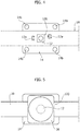
- Figures 2 and 3 exemplify the possibility of providing thermally dissipative elements 14 with one or more magnetic inserts 14a.
- such magnetic inserts may enable mounting on a magnetically attractable surface and, optionally, may also help retaining element 14 on substrate or support 10 by taking advantage of the ferromagnetic properties of support 10 itself, which are given e.g. by the presence of the electrically conductive layer including the electrically conductive lines for supplying and/or controlling sources 12.
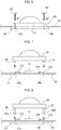
- holes 14 may be provided in elements 14, to enable e.g. the fixation of accessories, such as e.g. optical accessories as optical accessories as exemplified in Figures 5 to 8 .
- substrate 10 may be arranged sandwich-like, optionally clamped, between the thermally dissipative element 14 and a complementary element 16.
- said element 16 may comprise, for example, an optical element such as a lens 16 or a reflector, adapted to be arranged in a position corresponding to the light radiation source 12, so as to perform e.g. a shaping action on the light radiation emitted by the Light Emitting Source (LES) of source 12.
- an optical element such as a lens 16 or a reflector
- connection between the thermally dissipative element 14 and the complementary element 16 e.g. a lens or a reflector
- the connection between the thermally dissipative element 14 and the complementary element 16 may be obtained by various means such as, for example:
- the thermally dissipative element 14 may be wider than substrate 10, the holes 14 being located externally of the edges of substrate 10 (see e.g. Figure 4 ), so that said fixation elements (screws 18 or pins 20) may extend within holes 14b sidewise of support 10.
- thermally dissipative elements 14 may be coupled to support 10 by lamination.
- Such a method may envisage the application, between elements 14 and substrate 10, of an adhesive which is dispensed as a glue or is formed as a layer (adhesive tape).
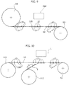
- Figure 9 shows, by way of example, a solution wherein the support structure including substrate 10 with elements 14 applied on the back face is unwound from a ribbon or reel R1, then is fed to a P&P processing station in which (e.g. by means of a Pick & Place procedure) light radiation sources 12 (with optional associated circuits which are not visible in the Figures) are applied on the front face of ribbon 10, in positions corresponding to locations 120.
- a P&P processing station in which (e.g. by means of a Pick & Place procedure) light radiation sources 12 (with optional associated circuits which are not visible in the Figures) are applied on the front face of ribbon 10, in positions corresponding to locations 120.
- the subsequent step consists in winding the thus finished lighting device onto an output ribbon or reel R2.
- a method as schematically shown in Figure 9 may be implemented in manufacturing support 10 as a Flexible Printed Circuit (FPC) so as to obtain a so-called panel.
- FPC Flexible Printed Circuit
- a process as exemplified in Figure 9 may be implemented in parallel on a plurality of substrates 10, which are unwound from reel R1 as a single sheet and are subsequently separated via a lengthwise cut at the end of the manufacturing process, so as to originate a plurality of LED strips or modules which may be cut to length according to the application needs.
- Figure 10 exemplifies, as an overall similar solution, the possibility of unwinding substrate 10, which is already provided with light radiation sources 12 on the front face, from a reel R11, and feeding it to a lamination station schematically denoted as L.
- thermally dissipative elements 14 may be applied (again according to the previously outlined method) onto the back face of substrate 10, at distances which are set according to the mounting locations 120 of sources 12.
- elements 14 may be carried by an auxiliary tape T which is unwound from reel R12.
- the resulting lighting device i.e. support 10 having the light radiation sources 12 on the front face and the thermally dissipative elements 14 on the back face
- the resulting lighting device may be wound onto an output reel R2.
- the coupling operations of the ribbons unwound from reels R11 and R12 may take place on laminar panels, which are subsequently divided into single strips (or proper modules) via a lengthwise cutting operation, as a final processing step.
- One or more embodiments may include (e.g. in a lighting device) a support structure for electrically-powered light radiation sources, the structure including a ribbon-like flexible substrate (e.g. 10) the front surface whereof comprises mounting locations (e.g. 120) for light radiation sources distributed therealong, the ribbon-like substrate having a back face opposed said front face with a plurality of thermally dissipative elements (e.g. 14) coupled to the back face of the ribbon-like substrate in positions opposed said mounting locations on said front surface.
- a support structure for electrically-powered light radiation sources the structure including a ribbon-like flexible substrate (e.g. 10) the front surface whereof comprises mounting locations (e.g. 120) for light radiation sources distributed therealong, the ribbon-like substrate having a back face opposed said front face with a plurality of thermally dissipative elements (e.g. 14) coupled to the back face of the ribbon-like substrate in positions opposed said mounting locations on said front surface.
- said thermally dissipative elements may be coupled to the back surface of the ribbon-like substrate by laminating them onto the ribbon-like substrate.
- said thermally dissipative elements may be coupled to a mounting surface via at least one means selected out of:
- a support structure as exemplified herein may be used in order to obtain a lighting device comprising, in addition to such a support structure, a plurality of electrically-powered light radiation sources (e.g. 12), preferably solid-state sources such as LED sources, which are arranged at said mounting locations on said front surface.
- electrically-powered light radiation sources e.g. 12
- solid-state sources such as LED sources
- said lighting device may be implemented in various ways such as, for example:
Landscapes
- Engineering & Computer Science (AREA)
- General Engineering & Computer Science (AREA)
- Manufacturing & Machinery (AREA)
- Physics & Mathematics (AREA)
- Microelectronics & Electronic Packaging (AREA)
- Optics & Photonics (AREA)
- Fastening Of Light Sources Or Lamp Holders (AREA)
Abstract
Description
- The description relates to lighting devices.
- One or more embodiments may find application in lighting devices employing electrically-powered light radiation sources such as solid-state sources, e.g. LED sources.
- Lighting devices including an elongate, e.g. ribbon-like, and flexible support, whereon light radiation sources such as LED sources are mounted, may offer a high degree of installation flexibility. Users (installers and possibly final users) may cut strings of proper length from a continuous reel.
- This procedure may however involve power limitations of the lighting sources, due to the heat generated by the latter in operation, to the requirements of the mounting surface (for example, wood or flammable materials must be avoided) or to the need of employing dedicated mounting profiles having thermally dissipative properties.
- For example, in order to avoid exceeding temperature safety limits, LED modules adapted to be cut to a desired length and to be used in power applications may require being mounted on thermally dissipative surfaces.
- In the case of mounting on non-dissipative surfaces (e.g. wood, plastic materials, certain kinds of drywalls), mounting profiles having thermal dissipation properties may be resorted to. Such profiles may however impose limitations due to their rigidity; this may reduce the benefits deriving from the flexibility of the lighting module itself.
- Moreover, such modules may be destined to be applied onto the mounting surface and/or into the thermally dissipative profile by means of an adhesive tape. The latter may form an additional thermal interface which may further limit thermal dissipation from light radiation sources, e.g. LED sources. The possible use of thermally conductive adhesive tapes has the disadvantage of a rather high cost.
- A further possible solution consists in using, as support surfaces for light radiation sources, semirigid elements similar to Printed Circuit Boards (PCBs) and made of materials such as Kapton or Aluminium. However, the drawback of this solution is the availability of such supports as single PCBs or panels, not as continuous reels which may be cut to length. This is an obvious limitation, as the presence of a continuous ribbon is one of the main advantages of flexible ("flex") LED modules.
- Document
US 8 975 532 B2 shows a solution wherein thermal dissipation may be favoured by means of copper pads on the PCB, which requires a certain width of the Flexible Printed Circuits (FPCs) or strips, with a consequent limitation of the possible application fields. - One or more embodiments aim at overcoming the previously outlined limitations.
- According to one or more embodiments, said object may be achieved thanks to a support structure for lighting devices having the features specifically set forth in the claims that follow.
- One or more embodiments may also concern a corresponding lighting device, as well as a corresponding method.
- The claims are an integral part of the technical teaching provided herein with reference to the embodiments.
- In one or more embodiments, the problem of providing a satisfying level of thermal dissipation in flexible lighting modules, e.g. so-called "flex" modules, is solved via the application of thermally dissipative elements, so as to preserve the intrinsic advantages of ribbon-like modules which may be cut to length.
- One or more embodiments enable to achieve one or more of the following advantages:
- higher thermal dissipation capability than standard flexible, e.g. LED, strips/modules, the possibility being given of using thermally dissipative elements integrated as stand-alone components, without the need of providing additional heatsinks (so-called self-cooling capability), and with the option of installation on non-thermally dissipative supports;
- possibility of manufacturing continuous modules, e.g. as flexible strips, adapted to be cut to length by final users, the possibility being offered of reducing manufacturing costs while avoiding splicing (another advantage for final users);
- possibility of implementing an in-house lamination of thermally dissipative elements, with a consequent increase of the product portfolio, because the same module may be marketed both with and without the provision of thermally dissipative elements;
- benefits regarding shipping, stocking and generally handling thanks to the possible use of reel-to-reel technology, while enhancing the thermal dissipation properties of the flexible modules themselves;
- possibility of coupling strip-shaped substrates, e.g. adapted to carry power LEDs, to thermally dissipative elements having various sizes and shapes, with the consequent option of further widening the product portfolio by using only a small number of premanufactured flexile modules;
- possibility of using the thermally dissipative elements in order to implement alternative installation methods, which show a higher efficiency in thermal dissipation than e.g. adhesive tapes; for instance, magnetic inserts may be provided on thermally dissipative elements, so as to enable the fixation on ferromagnetic materials; as an alternative, holes may be present for a fixation via screws;
- possibility of using the thermally dissipative elements as supports for lenses or other optical accessories, which may be coupled to the thermally dissipative elements e.g. via screws, mechanical interference or clips.
- One or more embodiments will now be described, by way of non-limiting example only, with reference to the annexed Figures, wherein:
-
Figure 1 exemplifies a general principle on which one or more embodiments may be based, -
Figures 2 and 3 exemplify, respectively in side elevation and in top view, one or more embodiments, -
Figures 4 and 5 exemplify, in further top views, one or more embodiments, -
Figures 6 to 8 exemplify various possible implementations of embodiments, and -
Figures 9 and 10 exemplify possible implementation criteria of methods according to one or more embodiments. - It will be appreciated that, for clarity of illustration, the various Figures may not be drawn to the same scale.
- In the following description, numerous specific details are given in order to provide a thorough understanding of various exemplary embodiments. The embodiments may be practiced without one or several of the specific details, or with other methods, components, materials, etc. In other instances, well-known structures, materials, or operations are not shown or described in detail to avoid obscuring the various aspects of the embodiments.
- Reference throughout this specification to "one embodiment" or "an embodiment" means that a particular feature, structure, or characteristic described in connection with the embodiment is included in at least one embodiment. Thus, the possible appearances of the phrases "in one embodiment" or "in an embodiment" in various places throughout this specification are not necessarily all referring exactly to the same embodiment. Furthermore, particular features, structures, or characteristics may be combined in any suitable manner in one or more embodiments.
- The headings provided herein are given for convenience only, and therefore do not interpret the extent of protection or the scope of the embodiments.
- One or more embodiments may envisage the integration of thermally dissipative elements (e.g. of a metal material such as copper), having a plurality of shapes, into a ribbon-like elongate assembly, substantially similar to a Printed Circuit Board (PCB), carrying electrically-powered light radiation sources, such as e.g. solid-state light radiation sources, e.g. LED sources, and/or possible further elements adapted to generate heat in operation: by way of non-limiting example we may mention the drivers / regulating circuits which may be associated to the previously mentioned light radiation sources.
- In one or more embodiments,
reference 10 denotes a ribbon-like substrate or support, substantially similar to a Flexible Printed Circuit (FPC). - In one or more embodiments,
support 10 may include a continuous strip, including at least one electrically insulating layer and at least one electrically conductive layer. - In one or more embodiments, the electrically insulating layer may include e.g. a polymer, such as polyimide or other materials known for this purpose (e.g. polyethylene naphtalate, polyester, FR4).
- In one or more embodiments, the electrically conductive layer may take the form of an arrangement or pattern of electrically conductive (e.g. copper) lines, which may be used for supplying (and optionally for controlling e.g. the temperature or the light emission intensity - so-called "dimming") of electrically-powered light radiation sources, such as solid-state sources e.g. LED sources.
- In one or more embodiments such sources, denoted as 12, may be mounted at mounting
locations 120 arranged on the front face ofsubstrate 10. - On said substrate (e.g. on the front face or surface thereof) there may optionally be arranged electric/electronic components/
circuits 12, for the supply and/or the driving ofsources 12, e.g. in order to perform current regulating and/or voltage balancing functions, according to the application needs. Such lighting modules/devices are known in themselves, which makes it unnecessary to provide a more detailed description herein. - One or more embodiments may envisage the coupling, to the presently exemplified support structure, of thermally
dissipative elements 14, arranged on the back face o side ofsubstrate 10, i.e. on the side or face opposed the (front) face whereonsources 12 will be placed (together withcircuits 12 optionally associated therewith). - In one or more embodiments, thermally
dissipative elements 14 may include (or may be comprised of) plates of thermally conductive material, e.g. a metal material such as copper. - In one or more embodiments (and as schematically exemplified in the Figures), said elements may include
single elements 14 arranged on the back face ofsubstrate 10 and located opposed thelocations 120 on the front face, for mounting sources 12 (and/or theassociated circuits 12a, which may be located in the vicinity thereof). - In one or more embodiments (as exemplified in
Figure 3 ),elements 14 andelement 10 may have the same width (in the transverse direction with reference to the lengthwise extension of substrate 10), e.g. in the view of a possible fixation ofelements 14 onsubstrate 10, e.g. via an adhesive tape. - In one or more embodiments, as exemplified e.g. in
Figures 4 and following, the thermallydissipative elements 14 may have a width (again in the transverse direction with reference to the lengthwise extension of substrate 10) larger than the width ofsubstrate 10. - In one or more embodiments other fixation procedures may be used for the coupling of
elements 14 tosubstrate 10. - For example,
Figures 2 and 3 exemplify the possibility of providing thermallydissipative elements 14 with one or moremagnetic inserts 14a. - In one or more embodiments, such magnetic inserts (or, optionally, the presence of magnetic features not only in the insert or
inserts 14a but in theelement 14 as a whole) may enable mounting on a magnetically attractable surface and, optionally, may also help retainingelement 14 on substrate orsupport 10 by taking advantage of the ferromagnetic properties ofsupport 10 itself, which are given e.g. by the presence of the electrically conductive layer including the electrically conductive lines for supplying and/or controllingsources 12. - In one or more embodiments (as may be the case of the embodiments exemplified in
Figures 4 and following, theelements 14 having a larger width than substrate 10),holes 14 may be provided inelements 14, to enable e.g. the fixation of accessories, such as e.g. optical accessories as optical accessories as exemplified inFigures 5 to 8 . - What previously exemplified is of course representative of only a few possible implementation examples of the embodiments.
- In one or more embodiments which are provided with fixation holes (see
e.g. holes 14b),substrate 10 may be arranged sandwich-like, optionally clamped, between thethermally dissipative element 14 and acomplementary element 16. - In one or more embodiments, said
element 16 may comprise, for example, an optical element such as alens 16 or a reflector, adapted to be arranged in a position corresponding to thelight radiation source 12, so as to perform e.g. a shaping action on the light radiation emitted by the Light Emitting Source (LES) ofsource 12. - The connection between the
thermally dissipative element 14 and the complementary element 16 (e.g. a lens or a reflector), which clamp or enclosesubstrate 10 sandwich-like therebetween, may be obtained by various means such as, for example: - screws 18 threading within
holes 14b (Figure 6 ), - pins achieving an interference fit within
holes 14b (Figure 7 ), - pins 20 having protruding formations (clips) 20a in their distal portion, which may achieve an interference fit within
holes 14b (Figure 8 ). - In such embodiments, the thermally
dissipative element 14 may be wider thansubstrate 10, theholes 14 being located externally of the edges of substrate 10 (see e.g.Figure 4 ), so that said fixation elements (screws 18 or pins 20) may extend withinholes 14b sidewise ofsupport 10. - In one or more embodiments, thermally
dissipative elements 14 may be coupled to support 10 by lamination. - Such a method (known in itself) may envisage the application, between
elements 14 andsubstrate 10, of an adhesive which is dispensed as a glue or is formed as a layer (adhesive tape). -
Figure 9 shows, by way of example, a solution wherein the supportstructure including substrate 10 withelements 14 applied on the back face is unwound from a ribbon or reel R1, then is fed to a P&P processing station in which (e.g. by means of a Pick & Place procedure) light radiation sources 12 (with optional associated circuits which are not visible in the Figures) are applied on the front face ofribbon 10, in positions corresponding tolocations 120. - The subsequent step consists in winding the thus finished lighting device onto an output ribbon or reel R2.
- A method as schematically shown in
Figure 9 may be implemented inmanufacturing support 10 as a Flexible Printed Circuit (FPC) so as to obtain a so-called panel. - A process as exemplified in
Figure 9 may be implemented in parallel on a plurality ofsubstrates 10, which are unwound from reel R1 as a single sheet and are subsequently separated via a lengthwise cut at the end of the manufacturing process, so as to originate a plurality of LED strips or modules which may be cut to length according to the application needs. -
Figure 10 exemplifies, as an overall similar solution, the possibility of unwindingsubstrate 10, which is already provided withlight radiation sources 12 on the front face, from a reel R11, and feeding it to a lamination station schematically denoted as L. - In station L, thermally
dissipative elements 14 may be applied (again according to the previously outlined method) onto the back face ofsubstrate 10, at distances which are set according to the mountinglocations 120 ofsources 12. - In one or more embodiments,
elements 14 may be carried by an auxiliary tape T which is unwound from reel R12. - This enables an in-house coupling operation with a conventional lighting device, available on the market, which comprises a
substrate 10 having thelight radiation sources 12 already mounted on its front face. - As in the case of
Figure 9 , the resulting lighting device (i.e.support 10 having thelight radiation sources 12 on the front face and the thermallydissipative elements 14 on the back face) may be wound onto an output reel R2. - Also in this instance, the coupling operations of the ribbons unwound from reels R11 and R12 may take place on laminar panels, which are subsequently divided into single strips (or proper modules) via a lengthwise cutting operation, as a final processing step.
- One or more embodiments, therefore, may include (e.g. in a lighting device) a support structure for electrically-powered light radiation sources, the structure including a ribbon-like flexible substrate (e.g. 10) the front surface whereof comprises mounting locations (e.g. 120) for light radiation sources distributed therealong, the ribbon-like substrate having a back face opposed said front face with a plurality of thermally dissipative elements (e.g. 14) coupled to the back face of the ribbon-like substrate in positions opposed said mounting locations on said front surface.
- In one or more embodiments, said thermally dissipative elements may be coupled to the back surface of the ribbon-like substrate by laminating them onto the ribbon-like substrate.
- In one or more embodiments, said thermally dissipative elements may be coupled to a mounting surface via at least one means selected out of:
- adhesive fixation,
- mechanical fixation,
- magnetic fixation.
- In one or more embodiments, a support structure as exemplified herein may be used in order to obtain a lighting device comprising, in addition to such a support structure, a plurality of electrically-powered light radiation sources (e.g. 12), preferably solid-state sources such as LED sources, which are arranged at said mounting locations on said front surface.
- In one or more embodiments, said lighting device may be implemented in various ways such as, for example:
- by providing a support structure as previously exemplified, and arranging (in succession) said light radiation sources on said support structure at said mounting locations on said front surface (see for example the diagram in
Figure 9 ),
or - by providing said ribbon-like substrate (e.g. 10) having said light radiation sources (already) arranged at said mounting locations on said front surface, and by coupling said thermally dissipative elements to the back surface of the ribbon-like substrate, in said positions opposed said mounting locations on said front surface, with said light radiation sources (already) arranged in the corresponding positions (see e.g. the diagram in
Figure 10 ). - Of course, without prejudice to the basic principle, the implementation details and the embodiments may vary, even appreciably, with respect to what has been described herein by way of non-limiting example only, without departing from the extent of protection.
- The extent of protection is defined by the annexed claims.
Claims (10)
- A support structure for light radiation sources (12), the structure including a ribbon-like flexible substrate (10) with a front surface having, distributed therealong, mounting locations (120) for electrically-powered light radiation sources (12), the ribbon-like substrate (10) having a back surface opposed said front surface with a plurality of thermally dissipative elements (14) coupled to the back surface of the ribbon-like substrate (10) at locations opposed said mounting locations (120) on said front surface.
- The support structure of claim 1, wherein said thermally dissipative elements (14) include metal material, preferably metal plates.
- The support structure of claim 1 or claim 2, wherein the ribbon-like substrate (10) has a width across its length and said thermally dissipative elements (14) have a width equal to the width of the ribbon-like substrate (10).
- The support structure of claim 1 or claim 2, wherein the ribbon-like substrate (10) has a width across its length and said thermally dissipative elements (14) have a width larger than the width of the ribbon-like substrate (10).
- The support structure of any of the previous claims, wherein said thermally dissipative elements (14) include at least one magnetic portion (14a).
- The support structure of any of the previous claims, wherein said thermally dissipative elements (14) are coupled to the back surface of said ribbon-like substrate (10) by lamination (L) to the ribbon-like substrate (10).
- The support structure of any of the previous claims, wherein said thermally dissipative elements (14) are coupleable to a mounting surface by at least one means selected out of:- adhesive fixation,- mechanical fixation,- magnetic fixation (14, 14a).
- The support structure of any of the previous claims, wherein said thermally dissipative elements (14) are coupled to the back surface of said ribbon-like substrate (10) with said thermally dissipative elements (14) cooperating with a complementary element (16) with the ribbon-like substrate (10) sandwiched between the thermally dissipative element (14) and the complementary element (16), said complementary element (16) preferably including an optical element.
- A lighting device, including:- a support structure according to any of claims 1 to 8, and- a plurality of electrically-powered light radiation sources (12), preferably solid-state sources such as LED sources LED (12), arranged at said mounting locations (120) on said front surface.
- A method of providing a lighting device according to claim 9, including one out of:- providing a support structure according to any of claims 1 to 8 and arranging said light radiation sources (12) on said support structure at said mounting locations (120) on said front surface, or- providing said ribbon-like substrate (10) with said light radiation sources (12) arranged at said mounting locations (120) on said front surface, and coupling said thermally dissipative elements (14) to the back surface del ribbon-like substrate (10) at said locations opposed said mounting locations (120) on said front surface with said light radiation sources (12) arranged thereat.
Applications Claiming Priority (1)
| Application Number | Priority Date | Filing Date | Title |
|---|---|---|---|
| ITUB20160552 | 2016-02-08 |
Publications (3)
| Publication Number | Publication Date |
|---|---|
| EP3203146A1 true EP3203146A1 (en) | 2017-08-09 |
| EP3203146A8 EP3203146A8 (en) | 2017-10-18 |
| EP3203146B1 EP3203146B1 (en) | 2018-10-31 |
Family
ID=55948951
Family Applications (1)
| Application Number | Title | Priority Date | Filing Date |
|---|---|---|---|
| EP17152604.9A Not-in-force EP3203146B1 (en) | 2016-02-08 | 2017-01-23 | Support structure for light radiation sources, corresponding device and method |
Country Status (2)
| Country | Link |
|---|---|
| US (1) | US20170227179A1 (en) |
| EP (1) | EP3203146B1 (en) |
Families Citing this family (1)
| Publication number | Priority date | Publication date | Assignee | Title |
|---|---|---|---|---|
| CN111174112A (en) * | 2019-11-25 | 2020-05-19 | 苏州汉瑞森光电科技股份有限公司 | LED module structure |
Citations (6)
| Publication number | Priority date | Publication date | Assignee | Title |
|---|---|---|---|---|
| DE102007002838A1 (en) * | 2006-09-08 | 2008-03-27 | Robert Bosch Gmbh | Vehicle lamp, for interior and exterior illumination, has a number of LEDs fitted into a cooling body to take off heat |
| US20100277666A1 (en) * | 2007-05-22 | 2010-11-04 | OSRAM Gelsellschaft mit beschrankter | Lighting Device, Backlighting Device, and Display Device |
| WO2011151272A1 (en) * | 2010-05-30 | 2011-12-08 | Stephan Gunst | Light fitting for led strips |
| JP2012043756A (en) * | 2010-08-23 | 2012-03-01 | Explore:Kk | Lighting system |
| US8975532B2 (en) | 2004-02-26 | 2015-03-10 | OSPAM Opto Semiconductor GmbH | Light-emitting diode arrangement for a high-power light-emitting diode and method for producing a light-emitting diode arrangement |
| US20150159812A1 (en) * | 2013-12-06 | 2015-06-11 | Osram Sylvania Inc. | Substrates with stiffeners for lighting and electronic applications |
Family Cites Families (7)
| Publication number | Priority date | Publication date | Assignee | Title |
|---|---|---|---|---|
| TW558804B (en) * | 2002-04-16 | 2003-10-21 | Yuan Lin | Flexible light emitting device and the manufacturing method thereof |
| US7128442B2 (en) * | 2003-05-09 | 2006-10-31 | Kian Shin Lee | Illumination unit with a solid-state light generating source, a flexible substrate, and a flexible and optically transparent encapsulant |
| JP2012049367A (en) * | 2010-08-27 | 2012-03-08 | Kyocera Elco Corp | Semiconductor light-emitting device attachment module, semiconductor light-emitting device module, semiconductor light-emitting device lighting apparatus, and manufacturing method of semiconductor light-emitting device attachment module |
| JP6060578B2 (en) * | 2012-09-14 | 2017-01-18 | 日亜化学工業株式会社 | Light emitting device |
| US10900653B2 (en) * | 2013-11-01 | 2021-01-26 | Cree Hong Kong Limited | LED mini-linear light engine |
| ES2532051B1 (en) * | 2014-08-05 | 2016-01-04 | The Mad Pixel Factory S.L. | LED lighting device |
| US10655805B2 (en) * | 2015-12-02 | 2020-05-19 | Zyntony, Inc. | Multi-element flexible strap light |
-
2017
- 2017-01-23 EP EP17152604.9A patent/EP3203146B1/en not_active Not-in-force
- 2017-01-26 US US15/415,947 patent/US20170227179A1/en not_active Abandoned
Patent Citations (6)
| Publication number | Priority date | Publication date | Assignee | Title |
|---|---|---|---|---|
| US8975532B2 (en) | 2004-02-26 | 2015-03-10 | OSPAM Opto Semiconductor GmbH | Light-emitting diode arrangement for a high-power light-emitting diode and method for producing a light-emitting diode arrangement |
| DE102007002838A1 (en) * | 2006-09-08 | 2008-03-27 | Robert Bosch Gmbh | Vehicle lamp, for interior and exterior illumination, has a number of LEDs fitted into a cooling body to take off heat |
| US20100277666A1 (en) * | 2007-05-22 | 2010-11-04 | OSRAM Gelsellschaft mit beschrankter | Lighting Device, Backlighting Device, and Display Device |
| WO2011151272A1 (en) * | 2010-05-30 | 2011-12-08 | Stephan Gunst | Light fitting for led strips |
| JP2012043756A (en) * | 2010-08-23 | 2012-03-01 | Explore:Kk | Lighting system |
| US20150159812A1 (en) * | 2013-12-06 | 2015-06-11 | Osram Sylvania Inc. | Substrates with stiffeners for lighting and electronic applications |
Also Published As
| Publication number | Publication date |
|---|---|
| EP3203146B1 (en) | 2018-10-31 |
| US20170227179A1 (en) | 2017-08-10 |
| EP3203146A8 (en) | 2017-10-18 |
Similar Documents
| Publication | Publication Date | Title |
|---|---|---|
| US11647572B2 (en) | Lighting systems incorporating connections for signal and power transmission | |
| US8496350B2 (en) | Wiring board contributable to reduction in thickness of light emitting apparatus and having high versatility | |
| US8143631B2 (en) | Layered structure for use with high power light emitting diode systems | |
| US11690172B2 (en) | LED lighting systems and methods | |
| US10018311B2 (en) | Lighting device and corresponding mounting housing, kit and method | |
| US20030193803A1 (en) | Flexible rod light device formed of chip on board based LED lamps and manufacturing method thereof | |
| JP5681436B2 (en) | Light emitting device and lighting device | |
| US10094516B2 (en) | LED light arrangement with flexible circuit board having graphite substrate | |
| US20250008653A1 (en) | Interconnectable circuit boards adapted for three-dimensional constructions as lighting sources | |
| WO2021239150A1 (en) | Track lighting system | |
| US20130188357A1 (en) | Channel letter lighting system using high output white light emitting diodes | |
| EP3203146B1 (en) | Support structure for light radiation sources, corresponding device and method | |
| US20100149811A1 (en) | Channel letter lighting system using high output white light emitting diodes | |
| CN102683549A (en) | Substrate used for installing leds and method for manufacturing led module | |
| JP6511914B2 (en) | LED mounting module and LED display device | |
| JP6922229B2 (en) | LED backlight | |
| JP2022021922A (en) | Led illumination module for growing plants and animals, shelf for growing plants and animals and factory for growing plants and animals | |
| WO2016104609A1 (en) | Led element substrate, led-mounted module and led display device using these | |
| JP6001694B2 (en) | Manufacturing method of lighting device | |
| JP6458493B2 (en) | LED element substrate and manufacturing method of LED mounting module using the same | |
| JP6458492B2 (en) | LED element substrate and manufacturing method of LED mounting module using the same | |
| JP6148382B2 (en) | Light emitting device and lighting device | |
| JP2017152450A (en) | LED display device | |
| EP3297409B1 (en) | A method of connecting lighting modules and corresponding device | |
| CN104728788A (en) | Backlight module |
Legal Events
| Date | Code | Title | Description |
|---|---|---|---|
| PUAI | Public reference made under article 153(3) epc to a published international application that has entered the european phase |
Free format text: ORIGINAL CODE: 0009012 |
|
| STAA | Information on the status of an ep patent application or granted ep patent |
Free format text: STATUS: THE APPLICATION HAS BEEN PUBLISHED |
|
| AK | Designated contracting states |
Kind code of ref document: A1 Designated state(s): AL AT BE BG CH CY CZ DE DK EE ES FI FR GB GR HR HU IE IS IT LI LT LU LV MC MK MT NL NO PL PT RO RS SE SI SK SM TR |
|
| AX | Request for extension of the european patent |
Extension state: BA ME |
|
| RAP1 | Party data changed (applicant data changed or rights of an application transferred) |
Owner name: OSRAM GMBH Owner name: OSRAM S.P.A. - SOCIETA' RIUNITE OSRAM EDISON CLERI |
|
| STAA | Information on the status of an ep patent application or granted ep patent |
Free format text: STATUS: REQUEST FOR EXAMINATION WAS MADE |
|
| 17P | Request for examination filed |
Effective date: 20180205 |
|
| RBV | Designated contracting states (corrected) |
Designated state(s): AL AT BE BG CH CY CZ DE DK EE ES FI FR GB GR HR HU IE IS IT LI LT LU LV MC MK MT NL NO PL PT RO RS SE SI SK SM TR |
|
| GRAP | Despatch of communication of intention to grant a patent |
Free format text: ORIGINAL CODE: EPIDOSNIGR1 |
|
| STAA | Information on the status of an ep patent application or granted ep patent |
Free format text: STATUS: GRANT OF PATENT IS INTENDED |
|
| RIC1 | Information provided on ipc code assigned before grant |
Ipc: F21Y 103/10 20160101ALN20180503BHEP Ipc: F21Y 115/10 20160101ALN20180503BHEP Ipc: F21V 29/503 20150101ALI20180503BHEP Ipc: F21V 21/096 20060101AFI20180503BHEP Ipc: F21S 4/24 20160101ALI20180503BHEP |
|
| INTG | Intention to grant announced |
Effective date: 20180605 |
|
| GRAS | Grant fee paid |
Free format text: ORIGINAL CODE: EPIDOSNIGR3 |
|
| GRAA | (expected) grant |
Free format text: ORIGINAL CODE: 0009210 |
|
| STAA | Information on the status of an ep patent application or granted ep patent |
Free format text: STATUS: THE PATENT HAS BEEN GRANTED |
|
| AK | Designated contracting states |
Kind code of ref document: B1 Designated state(s): AL AT BE BG CH CY CZ DE DK EE ES FI FR GB GR HR HU IE IS IT LI LT LU LV MC MK MT NL NO PL PT RO RS SE SI SK SM TR |
|
| REG | Reference to a national code |
Ref country code: GB Ref legal event code: FG4D Ref country code: CH Ref legal event code: EP |
|
| REG | Reference to a national code |
Ref country code: AT Ref legal event code: REF Ref document number: 1059835 Country of ref document: AT Kind code of ref document: T Effective date: 20181115 |
|
| REG | Reference to a national code |
Ref country code: DE Ref legal event code: R096 Ref document number: 602017000719 Country of ref document: DE |
|
| REG | Reference to a national code |
Ref country code: IE Ref legal event code: FG4D |
|
| REG | Reference to a national code |
Ref country code: NL Ref legal event code: MP Effective date: 20181031 |
|
| REG | Reference to a national code |
Ref country code: LT Ref legal event code: MG4D |
|
| REG | Reference to a national code |
Ref country code: AT Ref legal event code: MK05 Ref document number: 1059835 Country of ref document: AT Kind code of ref document: T Effective date: 20181031 |
|
| PG25 | Lapsed in a contracting state [announced via postgrant information from national office to epo] |
Ref country code: FI Free format text: LAPSE BECAUSE OF FAILURE TO SUBMIT A TRANSLATION OF THE DESCRIPTION OR TO PAY THE FEE WITHIN THE PRESCRIBED TIME-LIMIT Effective date: 20181031 Ref country code: LV Free format text: LAPSE BECAUSE OF FAILURE TO SUBMIT A TRANSLATION OF THE DESCRIPTION OR TO PAY THE FEE WITHIN THE PRESCRIBED TIME-LIMIT Effective date: 20181031 Ref country code: IS Free format text: LAPSE BECAUSE OF FAILURE TO SUBMIT A TRANSLATION OF THE DESCRIPTION OR TO PAY THE FEE WITHIN THE PRESCRIBED TIME-LIMIT Effective date: 20190228 Ref country code: ES Free format text: LAPSE BECAUSE OF FAILURE TO SUBMIT A TRANSLATION OF THE DESCRIPTION OR TO PAY THE FEE WITHIN THE PRESCRIBED TIME-LIMIT Effective date: 20181031 Ref country code: AT Free format text: LAPSE BECAUSE OF FAILURE TO SUBMIT A TRANSLATION OF THE DESCRIPTION OR TO PAY THE FEE WITHIN THE PRESCRIBED TIME-LIMIT Effective date: 20181031 Ref country code: HR Free format text: LAPSE BECAUSE OF FAILURE TO SUBMIT A TRANSLATION OF THE DESCRIPTION OR TO PAY THE FEE WITHIN THE PRESCRIBED TIME-LIMIT Effective date: 20181031 Ref country code: NO Free format text: LAPSE BECAUSE OF FAILURE TO SUBMIT A TRANSLATION OF THE DESCRIPTION OR TO PAY THE FEE WITHIN THE PRESCRIBED TIME-LIMIT Effective date: 20190131 Ref country code: BG Free format text: LAPSE BECAUSE OF FAILURE TO SUBMIT A TRANSLATION OF THE DESCRIPTION OR TO PAY THE FEE WITHIN THE PRESCRIBED TIME-LIMIT Effective date: 20190131 Ref country code: PL Free format text: LAPSE BECAUSE OF FAILURE TO SUBMIT A TRANSLATION OF THE DESCRIPTION OR TO PAY THE FEE WITHIN THE PRESCRIBED TIME-LIMIT Effective date: 20181031 Ref country code: LT Free format text: LAPSE BECAUSE OF FAILURE TO SUBMIT A TRANSLATION OF THE DESCRIPTION OR TO PAY THE FEE WITHIN THE PRESCRIBED TIME-LIMIT Effective date: 20181031 |
|
| PG25 | Lapsed in a contracting state [announced via postgrant information from national office to epo] |
Ref country code: NL Free format text: LAPSE BECAUSE OF FAILURE TO SUBMIT A TRANSLATION OF THE DESCRIPTION OR TO PAY THE FEE WITHIN THE PRESCRIBED TIME-LIMIT Effective date: 20181031 Ref country code: SE Free format text: LAPSE BECAUSE OF FAILURE TO SUBMIT A TRANSLATION OF THE DESCRIPTION OR TO PAY THE FEE WITHIN THE PRESCRIBED TIME-LIMIT Effective date: 20181031 Ref country code: AL Free format text: LAPSE BECAUSE OF FAILURE TO SUBMIT A TRANSLATION OF THE DESCRIPTION OR TO PAY THE FEE WITHIN THE PRESCRIBED TIME-LIMIT Effective date: 20181031 Ref country code: GR Free format text: LAPSE BECAUSE OF FAILURE TO SUBMIT A TRANSLATION OF THE DESCRIPTION OR TO PAY THE FEE WITHIN THE PRESCRIBED TIME-LIMIT Effective date: 20190201 Ref country code: RS Free format text: LAPSE BECAUSE OF FAILURE TO SUBMIT A TRANSLATION OF THE DESCRIPTION OR TO PAY THE FEE WITHIN THE PRESCRIBED TIME-LIMIT Effective date: 20181031 Ref country code: PT Free format text: LAPSE BECAUSE OF FAILURE TO SUBMIT A TRANSLATION OF THE DESCRIPTION OR TO PAY THE FEE WITHIN THE PRESCRIBED TIME-LIMIT Effective date: 20190301 |
|
| PG25 | Lapsed in a contracting state [announced via postgrant information from national office to epo] |
Ref country code: CZ Free format text: LAPSE BECAUSE OF FAILURE TO SUBMIT A TRANSLATION OF THE DESCRIPTION OR TO PAY THE FEE WITHIN THE PRESCRIBED TIME-LIMIT Effective date: 20181031 Ref country code: DK Free format text: LAPSE BECAUSE OF FAILURE TO SUBMIT A TRANSLATION OF THE DESCRIPTION OR TO PAY THE FEE WITHIN THE PRESCRIBED TIME-LIMIT Effective date: 20181031 Ref country code: IT Free format text: LAPSE BECAUSE OF FAILURE TO SUBMIT A TRANSLATION OF THE DESCRIPTION OR TO PAY THE FEE WITHIN THE PRESCRIBED TIME-LIMIT Effective date: 20181031 |
|
| REG | Reference to a national code |
Ref country code: DE Ref legal event code: R097 Ref document number: 602017000719 Country of ref document: DE |
|
| PG25 | Lapsed in a contracting state [announced via postgrant information from national office to epo] |
Ref country code: EE Free format text: LAPSE BECAUSE OF FAILURE TO SUBMIT A TRANSLATION OF THE DESCRIPTION OR TO PAY THE FEE WITHIN THE PRESCRIBED TIME-LIMIT Effective date: 20181031 Ref country code: SK Free format text: LAPSE BECAUSE OF FAILURE TO SUBMIT A TRANSLATION OF THE DESCRIPTION OR TO PAY THE FEE WITHIN THE PRESCRIBED TIME-LIMIT Effective date: 20181031 Ref country code: SM Free format text: LAPSE BECAUSE OF FAILURE TO SUBMIT A TRANSLATION OF THE DESCRIPTION OR TO PAY THE FEE WITHIN THE PRESCRIBED TIME-LIMIT Effective date: 20181031 Ref country code: RO Free format text: LAPSE BECAUSE OF FAILURE TO SUBMIT A TRANSLATION OF THE DESCRIPTION OR TO PAY THE FEE WITHIN THE PRESCRIBED TIME-LIMIT Effective date: 20181031 Ref country code: MC Free format text: LAPSE BECAUSE OF FAILURE TO SUBMIT A TRANSLATION OF THE DESCRIPTION OR TO PAY THE FEE WITHIN THE PRESCRIBED TIME-LIMIT Effective date: 20181031 |
|
| PLBE | No opposition filed within time limit |
Free format text: ORIGINAL CODE: 0009261 |
|
| STAA | Information on the status of an ep patent application or granted ep patent |
Free format text: STATUS: NO OPPOSITION FILED WITHIN TIME LIMIT |
|
| PG25 | Lapsed in a contracting state [announced via postgrant information from national office to epo] |
Ref country code: LU Free format text: LAPSE BECAUSE OF NON-PAYMENT OF DUE FEES Effective date: 20190123 |
|
| 26N | No opposition filed |
Effective date: 20190801 |
|
| REG | Reference to a national code |
Ref country code: BE Ref legal event code: MM Effective date: 20190131 |
|
| REG | Reference to a national code |
Ref country code: IE Ref legal event code: MM4A |
|
| PG25 | Lapsed in a contracting state [announced via postgrant information from national office to epo] |
Ref country code: FR Free format text: LAPSE BECAUSE OF NON-PAYMENT OF DUE FEES Effective date: 20190131 Ref country code: SI Free format text: LAPSE BECAUSE OF FAILURE TO SUBMIT A TRANSLATION OF THE DESCRIPTION OR TO PAY THE FEE WITHIN THE PRESCRIBED TIME-LIMIT Effective date: 20181031 |
|
| PG25 | Lapsed in a contracting state [announced via postgrant information from national office to epo] |
Ref country code: BE Free format text: LAPSE BECAUSE OF NON-PAYMENT OF DUE FEES Effective date: 20190131 |
|
| PG25 | Lapsed in a contracting state [announced via postgrant information from national office to epo] |
Ref country code: IE Free format text: LAPSE BECAUSE OF NON-PAYMENT OF DUE FEES Effective date: 20190123 |
|
| PG25 | Lapsed in a contracting state [announced via postgrant information from national office to epo] |
Ref country code: TR Free format text: LAPSE BECAUSE OF FAILURE TO SUBMIT A TRANSLATION OF THE DESCRIPTION OR TO PAY THE FEE WITHIN THE PRESCRIBED TIME-LIMIT Effective date: 20181031 |
|
| PG25 | Lapsed in a contracting state [announced via postgrant information from national office to epo] |
Ref country code: MT Free format text: LAPSE BECAUSE OF NON-PAYMENT OF DUE FEES Effective date: 20190123 |
|
| REG | Reference to a national code |
Ref country code: CH Ref legal event code: PL |
|
| PG25 | Lapsed in a contracting state [announced via postgrant information from national office to epo] |
Ref country code: LI Free format text: LAPSE BECAUSE OF NON-PAYMENT OF DUE FEES Effective date: 20200131 Ref country code: CH Free format text: LAPSE BECAUSE OF NON-PAYMENT OF DUE FEES Effective date: 20200131 |
|
| PG25 | Lapsed in a contracting state [announced via postgrant information from national office to epo] |
Ref country code: CY Free format text: LAPSE BECAUSE OF FAILURE TO SUBMIT A TRANSLATION OF THE DESCRIPTION OR TO PAY THE FEE WITHIN THE PRESCRIBED TIME-LIMIT Effective date: 20181031 |
|
| PG25 | Lapsed in a contracting state [announced via postgrant information from national office to epo] |
Ref country code: HU Free format text: LAPSE BECAUSE OF FAILURE TO SUBMIT A TRANSLATION OF THE DESCRIPTION OR TO PAY THE FEE WITHIN THE PRESCRIBED TIME-LIMIT; INVALID AB INITIO Effective date: 20170123 |
|
| GBPC | Gb: european patent ceased through non-payment of renewal fee |
Effective date: 20210123 |
|
| PG25 | Lapsed in a contracting state [announced via postgrant information from national office to epo] |
Ref country code: GB Free format text: LAPSE BECAUSE OF NON-PAYMENT OF DUE FEES Effective date: 20210123 |
|
| PG25 | Lapsed in a contracting state [announced via postgrant information from national office to epo] |
Ref country code: MK Free format text: LAPSE BECAUSE OF FAILURE TO SUBMIT A TRANSLATION OF THE DESCRIPTION OR TO PAY THE FEE WITHIN THE PRESCRIBED TIME-LIMIT Effective date: 20181031 |
|
| REG | Reference to a national code |
Ref country code: DE Ref legal event code: R081 Ref document number: 602017000719 Country of ref document: DE Owner name: OPTOTRONIC GMBH, DE Free format text: FORMER OWNER: OSRAM GMBH, 80807 MUENCHEN, DE Ref country code: DE Ref legal event code: R081 Ref document number: 602017000719 Country of ref document: DE Owner name: INVENTRONICS GMBH, DE Free format text: FORMER OWNER: OSRAM GMBH, 80807 MUENCHEN, DE |
|
| PGFP | Annual fee paid to national office [announced via postgrant information from national office to epo] |
Ref country code: DE Payment date: 20240119 Year of fee payment: 8 |
|
| REG | Reference to a national code |
Ref country code: DE Ref legal event code: R081 Ref document number: 602017000719 Country of ref document: DE Owner name: INVENTRONICS GMBH, DE Free format text: FORMER OWNER: OPTOTRONIC GMBH, 85748 GARCHING, DE |
|
| REG | Reference to a national code |
Ref country code: DE Ref legal event code: R119 Ref document number: 602017000719 Country of ref document: DE |
|
| PG25 | Lapsed in a contracting state [announced via postgrant information from national office to epo] |
Ref country code: DE Free format text: LAPSE BECAUSE OF NON-PAYMENT OF DUE FEES Effective date: 20250801 |