EP3203041A1 - A steam turbine, a steam turbine nozzle, and a method of managing moisture in a steam turbine - Google Patents
A steam turbine, a steam turbine nozzle, and a method of managing moisture in a steam turbine Download PDFInfo
- Publication number
- EP3203041A1 EP3203041A1 EP16202996.1A EP16202996A EP3203041A1 EP 3203041 A1 EP3203041 A1 EP 3203041A1 EP 16202996 A EP16202996 A EP 16202996A EP 3203041 A1 EP3203041 A1 EP 3203041A1
- Authority
- EP
- European Patent Office
- Prior art keywords
- turbine
- moisture
- nozzle
- steam turbine
- removal
- Prior art date
- Legal status (The legal status is an assumption and is not a legal conclusion. Google has not performed a legal analysis and makes no representation as to the accuracy of the status listed.)
- Granted
Links
Images


Classifications
-
- F—MECHANICAL ENGINEERING; LIGHTING; HEATING; WEAPONS; BLASTING
- F01—MACHINES OR ENGINES IN GENERAL; ENGINE PLANTS IN GENERAL; STEAM ENGINES
- F01D—NON-POSITIVE DISPLACEMENT MACHINES OR ENGINES, e.g. STEAM TURBINES
- F01D9/00—Stators
- F01D9/02—Nozzles; Nozzle boxes; Stator blades; Guide conduits, e.g. individual nozzles
-
- F—MECHANICAL ENGINEERING; LIGHTING; HEATING; WEAPONS; BLASTING
- F01—MACHINES OR ENGINES IN GENERAL; ENGINE PLANTS IN GENERAL; STEAM ENGINES
- F01D—NON-POSITIVE DISPLACEMENT MACHINES OR ENGINES, e.g. STEAM TURBINES
- F01D25/00—Component parts, details, or accessories, not provided for in, or of interest apart from, other groups
- F01D25/32—Collecting of condensation water; Drainage ; Removing solid particles
-
- B—PERFORMING OPERATIONS; TRANSPORTING
- B23—MACHINE TOOLS; METAL-WORKING NOT OTHERWISE PROVIDED FOR
- B23K—SOLDERING OR UNSOLDERING; WELDING; CLADDING OR PLATING BY SOLDERING OR WELDING; CUTTING BY APPLYING HEAT LOCALLY, e.g. FLAME CUTTING; WORKING BY LASER BEAM
- B23K26/00—Working by laser beam, e.g. welding, cutting or boring
- B23K26/0006—Working by laser beam, e.g. welding, cutting or boring taking account of the properties of the material involved
-
- B—PERFORMING OPERATIONS; TRANSPORTING
- B23—MACHINE TOOLS; METAL-WORKING NOT OTHERWISE PROVIDED FOR
- B23K—SOLDERING OR UNSOLDERING; WELDING; CLADDING OR PLATING BY SOLDERING OR WELDING; CUTTING BY APPLYING HEAT LOCALLY, e.g. FLAME CUTTING; WORKING BY LASER BEAM
- B23K26/00—Working by laser beam, e.g. welding, cutting or boring
- B23K26/02—Positioning or observing the workpiece, e.g. with respect to the point of impact; Aligning, aiming or focusing the laser beam
- B23K26/06—Shaping the laser beam, e.g. by masks or multi-focusing
- B23K26/062—Shaping the laser beam, e.g. by masks or multi-focusing by direct control of the laser beam
- B23K26/0622—Shaping the laser beam, e.g. by masks or multi-focusing by direct control of the laser beam by shaping pulses
- B23K26/0624—Shaping the laser beam, e.g. by masks or multi-focusing by direct control of the laser beam by shaping pulses using ultrashort pulses, i.e. pulses of 1 ns or less
-
- B—PERFORMING OPERATIONS; TRANSPORTING
- B23—MACHINE TOOLS; METAL-WORKING NOT OTHERWISE PROVIDED FOR
- B23K—SOLDERING OR UNSOLDERING; WELDING; CLADDING OR PLATING BY SOLDERING OR WELDING; CUTTING BY APPLYING HEAT LOCALLY, e.g. FLAME CUTTING; WORKING BY LASER BEAM
- B23K26/00—Working by laser beam, e.g. welding, cutting or boring
- B23K26/352—Working by laser beam, e.g. welding, cutting or boring for surface treatment
-
- B—PERFORMING OPERATIONS; TRANSPORTING
- B23—MACHINE TOOLS; METAL-WORKING NOT OTHERWISE PROVIDED FOR
- B23K—SOLDERING OR UNSOLDERING; WELDING; CLADDING OR PLATING BY SOLDERING OR WELDING; CUTTING BY APPLYING HEAT LOCALLY, e.g. FLAME CUTTING; WORKING BY LASER BEAM
- B23K26/00—Working by laser beam, e.g. welding, cutting or boring
- B23K26/352—Working by laser beam, e.g. welding, cutting or boring for surface treatment
- B23K26/3568—Modifying rugosity
-
- B—PERFORMING OPERATIONS; TRANSPORTING
- B23—MACHINE TOOLS; METAL-WORKING NOT OTHERWISE PROVIDED FOR
- B23K—SOLDERING OR UNSOLDERING; WELDING; CLADDING OR PLATING BY SOLDERING OR WELDING; CUTTING BY APPLYING HEAT LOCALLY, e.g. FLAME CUTTING; WORKING BY LASER BEAM
- B23K26/00—Working by laser beam, e.g. welding, cutting or boring
- B23K26/36—Removing material
- B23K26/361—Removing material for deburring or mechanical trimming
-
- B—PERFORMING OPERATIONS; TRANSPORTING
- B23—MACHINE TOOLS; METAL-WORKING NOT OTHERWISE PROVIDED FOR
- B23K—SOLDERING OR UNSOLDERING; WELDING; CLADDING OR PLATING BY SOLDERING OR WELDING; CUTTING BY APPLYING HEAT LOCALLY, e.g. FLAME CUTTING; WORKING BY LASER BEAM
- B23K26/00—Working by laser beam, e.g. welding, cutting or boring
- B23K26/36—Removing material
- B23K26/40—Removing material taking account of the properties of the material involved
-
- B—PERFORMING OPERATIONS; TRANSPORTING
- B23—MACHINE TOOLS; METAL-WORKING NOT OTHERWISE PROVIDED FOR
- B23K—SOLDERING OR UNSOLDERING; WELDING; CLADDING OR PLATING BY SOLDERING OR WELDING; CUTTING BY APPLYING HEAT LOCALLY, e.g. FLAME CUTTING; WORKING BY LASER BEAM
- B23K26/00—Working by laser beam, e.g. welding, cutting or boring
- B23K26/60—Preliminary treatment
-
- F—MECHANICAL ENGINEERING; LIGHTING; HEATING; WEAPONS; BLASTING
- F01—MACHINES OR ENGINES IN GENERAL; ENGINE PLANTS IN GENERAL; STEAM ENGINES
- F01D—NON-POSITIVE DISPLACEMENT MACHINES OR ENGINES, e.g. STEAM TURBINES
- F01D5/00—Blades; Blade-carrying members; Heating, heat-insulating, cooling or antivibration means on the blades or the members
- F01D5/12—Blades
- F01D5/28—Selecting particular materials; Particular measures relating thereto; Measures against erosion or corrosion
- F01D5/286—Particular treatment of blades, e.g. to increase durability or resistance against corrosion or erosion
-
- F—MECHANICAL ENGINEERING; LIGHTING; HEATING; WEAPONS; BLASTING
- F01—MACHINES OR ENGINES IN GENERAL; ENGINE PLANTS IN GENERAL; STEAM ENGINES
- F01D—NON-POSITIVE DISPLACEMENT MACHINES OR ENGINES, e.g. STEAM TURBINES
- F01D9/00—Stators
- F01D9/02—Nozzles; Nozzle boxes; Stator blades; Guide conduits, e.g. individual nozzles
- F01D9/04—Nozzles; Nozzle boxes; Stator blades; Guide conduits, e.g. individual nozzles forming ring or sector
- F01D9/041—Nozzles; Nozzle boxes; Stator blades; Guide conduits, e.g. individual nozzles forming ring or sector using blades
-
- B—PERFORMING OPERATIONS; TRANSPORTING
- B23—MACHINE TOOLS; METAL-WORKING NOT OTHERWISE PROVIDED FOR
- B23K—SOLDERING OR UNSOLDERING; WELDING; CLADDING OR PLATING BY SOLDERING OR WELDING; CUTTING BY APPLYING HEAT LOCALLY, e.g. FLAME CUTTING; WORKING BY LASER BEAM
- B23K2101/00—Articles made by soldering, welding or cutting
- B23K2101/001—Turbines
-
- F—MECHANICAL ENGINEERING; LIGHTING; HEATING; WEAPONS; BLASTING
- F05—INDEXING SCHEMES RELATING TO ENGINES OR PUMPS IN VARIOUS SUBCLASSES OF CLASSES F01-F04
- F05D—INDEXING SCHEME FOR ASPECTS RELATING TO NON-POSITIVE-DISPLACEMENT MACHINES OR ENGINES, GAS-TURBINES OR JET-PROPULSION PLANTS
- F05D2220/00—Application
- F05D2220/30—Application in turbines
- F05D2220/31—Application in turbines in steam turbines
-
- F—MECHANICAL ENGINEERING; LIGHTING; HEATING; WEAPONS; BLASTING
- F05—INDEXING SCHEMES RELATING TO ENGINES OR PUMPS IN VARIOUS SUBCLASSES OF CLASSES F01-F04
- F05D—INDEXING SCHEME FOR ASPECTS RELATING TO NON-POSITIVE-DISPLACEMENT MACHINES OR ENGINES, GAS-TURBINES OR JET-PROPULSION PLANTS
- F05D2230/00—Manufacture
- F05D2230/10—Manufacture by removing material
-
- F—MECHANICAL ENGINEERING; LIGHTING; HEATING; WEAPONS; BLASTING
- F05—INDEXING SCHEMES RELATING TO ENGINES OR PUMPS IN VARIOUS SUBCLASSES OF CLASSES F01-F04
- F05D—INDEXING SCHEME FOR ASPECTS RELATING TO NON-POSITIVE-DISPLACEMENT MACHINES OR ENGINES, GAS-TURBINES OR JET-PROPULSION PLANTS
- F05D2230/00—Manufacture
- F05D2230/10—Manufacture by removing material
- F05D2230/13—Manufacture by removing material using lasers
-
- F—MECHANICAL ENGINEERING; LIGHTING; HEATING; WEAPONS; BLASTING
- F05—INDEXING SCHEMES RELATING TO ENGINES OR PUMPS IN VARIOUS SUBCLASSES OF CLASSES F01-F04
- F05D—INDEXING SCHEME FOR ASPECTS RELATING TO NON-POSITIVE-DISPLACEMENT MACHINES OR ENGINES, GAS-TURBINES OR JET-PROPULSION PLANTS
- F05D2240/00—Components
- F05D2240/10—Stators
- F05D2240/12—Fluid guiding means, e.g. vanes
- F05D2240/121—Fluid guiding means, e.g. vanes related to the leading edge of a stator vane
-
- F—MECHANICAL ENGINEERING; LIGHTING; HEATING; WEAPONS; BLASTING
- F05—INDEXING SCHEMES RELATING TO ENGINES OR PUMPS IN VARIOUS SUBCLASSES OF CLASSES F01-F04
- F05D—INDEXING SCHEME FOR ASPECTS RELATING TO NON-POSITIVE-DISPLACEMENT MACHINES OR ENGINES, GAS-TURBINES OR JET-PROPULSION PLANTS
- F05D2240/00—Components
- F05D2240/10—Stators
- F05D2240/12—Fluid guiding means, e.g. vanes
- F05D2240/123—Fluid guiding means, e.g. vanes related to the pressure side of a stator vane
-
- F—MECHANICAL ENGINEERING; LIGHTING; HEATING; WEAPONS; BLASTING
- F05—INDEXING SCHEMES RELATING TO ENGINES OR PUMPS IN VARIOUS SUBCLASSES OF CLASSES F01-F04
- F05D—INDEXING SCHEME FOR ASPECTS RELATING TO NON-POSITIVE-DISPLACEMENT MACHINES OR ENGINES, GAS-TURBINES OR JET-PROPULSION PLANTS
- F05D2260/00—Function
- F05D2260/60—Fluid transfer
- F05D2260/602—Drainage
-
- F—MECHANICAL ENGINEERING; LIGHTING; HEATING; WEAPONS; BLASTING
- F05—INDEXING SCHEMES RELATING TO ENGINES OR PUMPS IN VARIOUS SUBCLASSES OF CLASSES F01-F04
- F05D—INDEXING SCHEME FOR ASPECTS RELATING TO NON-POSITIVE-DISPLACEMENT MACHINES OR ENGINES, GAS-TURBINES OR JET-PROPULSION PLANTS
- F05D2300/00—Materials; Properties thereof
- F05D2300/50—Intrinsic material properties or characteristics
- F05D2300/51—Hydrophilic, i.e. being or having wettable properties
-
- F—MECHANICAL ENGINEERING; LIGHTING; HEATING; WEAPONS; BLASTING
- F05—INDEXING SCHEMES RELATING TO ENGINES OR PUMPS IN VARIOUS SUBCLASSES OF CLASSES F01-F04
- F05D—INDEXING SCHEME FOR ASPECTS RELATING TO NON-POSITIVE-DISPLACEMENT MACHINES OR ENGINES, GAS-TURBINES OR JET-PROPULSION PLANTS
- F05D2300/00—Materials; Properties thereof
- F05D2300/50—Intrinsic material properties or characteristics
- F05D2300/514—Porosity
-
- F—MECHANICAL ENGINEERING; LIGHTING; HEATING; WEAPONS; BLASTING
- F05—INDEXING SCHEMES RELATING TO ENGINES OR PUMPS IN VARIOUS SUBCLASSES OF CLASSES F01-F04
- F05D—INDEXING SCHEME FOR ASPECTS RELATING TO NON-POSITIVE-DISPLACEMENT MACHINES OR ENGINES, GAS-TURBINES OR JET-PROPULSION PLANTS
- F05D2300/00—Materials; Properties thereof
- F05D2300/50—Intrinsic material properties or characteristics
- F05D2300/516—Surface roughness
-
- F—MECHANICAL ENGINEERING; LIGHTING; HEATING; WEAPONS; BLASTING
- F05—INDEXING SCHEMES RELATING TO ENGINES OR PUMPS IN VARIOUS SUBCLASSES OF CLASSES F01-F04
- F05D—INDEXING SCHEME FOR ASPECTS RELATING TO NON-POSITIVE-DISPLACEMENT MACHINES OR ENGINES, GAS-TURBINES OR JET-PROPULSION PLANTS
- F05D2300/00—Materials; Properties thereof
- F05D2300/60—Properties or characteristics given to material by treatment or manufacturing
- F05D2300/612—Foam
-
- F—MECHANICAL ENGINEERING; LIGHTING; HEATING; WEAPONS; BLASTING
- F05—INDEXING SCHEMES RELATING TO ENGINES OR PUMPS IN VARIOUS SUBCLASSES OF CLASSES F01-F04
- F05D—INDEXING SCHEME FOR ASPECTS RELATING TO NON-POSITIVE-DISPLACEMENT MACHINES OR ENGINES, GAS-TURBINES OR JET-PROPULSION PLANTS
- F05D2300/00—Materials; Properties thereof
- F05D2300/60—Properties or characteristics given to material by treatment or manufacturing
- F05D2300/613—Felt
-
- F—MECHANICAL ENGINEERING; LIGHTING; HEATING; WEAPONS; BLASTING
- F05—INDEXING SCHEMES RELATING TO ENGINES OR PUMPS IN VARIOUS SUBCLASSES OF CLASSES F01-F04
- F05D—INDEXING SCHEME FOR ASPECTS RELATING TO NON-POSITIVE-DISPLACEMENT MACHINES OR ENGINES, GAS-TURBINES OR JET-PROPULSION PLANTS
- F05D2300/00—Materials; Properties thereof
- F05D2300/60—Properties or characteristics given to material by treatment or manufacturing
- F05D2300/614—Fibres or filaments
-
- Y—GENERAL TAGGING OF NEW TECHNOLOGICAL DEVELOPMENTS; GENERAL TAGGING OF CROSS-SECTIONAL TECHNOLOGIES SPANNING OVER SEVERAL SECTIONS OF THE IPC; TECHNICAL SUBJECTS COVERED BY FORMER USPC CROSS-REFERENCE ART COLLECTIONS [XRACs] AND DIGESTS
- Y02—TECHNOLOGIES OR APPLICATIONS FOR MITIGATION OR ADAPTATION AGAINST CLIMATE CHANGE
- Y02T—CLIMATE CHANGE MITIGATION TECHNOLOGIES RELATED TO TRANSPORTATION
- Y02T50/00—Aeronautics or air transport
- Y02T50/60—Efficient propulsion technologies, e.g. for aircraft
Definitions
- a typical steam turbine may include a high pressure section, an intermediate pressure section, and a low pressure section.
- the sections may be arranged in series with each section including any number of stages. Within the sections, work is extracted from the steam to drive the rotor. Between the sections, the steam may be reheated for performing work in the next section.
- the high pressure and the intermediate pressure sections may operate at relatively high temperatures so as to increase the overall steam turbine output.
- a steam turbine nozzle in another exemplary embodiment, includes a nozzle wall having an inner surface, an outer surface, at least one extraction opening through the nozzle wall from the outer surface to the inner surface, and a hydrophilic surface pattern on the outer surface of the nozzle wall adjacent the extraction opening.
- a greater volume of moisture is removed from the flow stream, because the frequency of droplets escaping the extraction openings is reduced. Reducing the number of slits or holes reduces manufacturing costs. Since the number of stress risers in the nozzles, caused by the inclusion of extraction openings, may be reduced with fewer slits/holes, less expensive materials may be used for nozzle manufacture.
- a hydrophilic surface pattern is positioned strategically in front of an extraction opening, which serves as an extraction point, to enable enhanced attraction of the condensed moisture from a greater surface area towards the extraction point.
- the extraction opening is a hole or a slit. This improves the volume of water that is extracted and may be used to reduce the number and size of holes or slits needed to accomplish effective reduction of erosion.
- the centrifugal force from the rotating rotor and buckets causes moisture deposited on the buckets to move away from the rotor and be deposited on the upper portion of the nozzles or on the casing.
- a hydrophilic surface pattern is positioned on a bucket to direct water downward toward the rotor and away from the casing.
- the centrifugal force from the rotating rotor and buckets causes moisture deposited on the buckets to move away from the rotor and toward the casing, and the hydrophilic surface pattern on the bucket serves to oppose some of that moisture movement.
- the hydrophilic surface pattern is preferably located to direct moisture toward the rotor from the area of the upper 40% of the length of the bucket.
- the hydrophilic surface pattern is more preferably located to direct moisture toward the rotor from the area of the upper 30% of the length of the bucket.
- the hydrophilic surface pattern may include a series of narrow patterns that also reduce the size of the droplets coming off the bucket by preventing coalescence of smaller droplets into larger droplets that cause greater erosion by impact with downstream surfaces.
- a hydrophilic surface pattern is positioned on the nozzle or the casing surface near a drain in the casing to enable enhanced attraction of the condensed moisture from a greater surface area towards the drain.
- Each of the HP section 105, the IP section 107, and the LP section 109 are connected along the rotor 101 via couplings 125.
- the couplings 125 may be mechanical couplings, such as bolted joints, or may be welded joints. In one embodiment, the couplings 125 permit detachment of any of the HP section 105, the IP section 107, and/or the LP section 109 for reconfiguration, service, or maintenance.
- the LP section 109 includes the turbine rotor 101 implanted circumferentially with buckets 131 and the casing 130 supporting nozzles 133.
- the buckets 131 and the nozzles 133 are arranged in stages in the axial direction of the turbine rotor 101.
- the buckets 131, casing 130, and nozzles 133 are constructed from materials including suitable known turbine bucket, casing, and nozzle materials, including, but not limited to, steel, stainless steel, precipitation-hardened stainless steel, aluminum, titanium, alloys thereof, or combinations thereof.
- the LP section 109 includes at least one removal surface 134 having an area with a hydrophilic surface pattern 135 directing surface moisture in at least one predetermined direction.
- the hydrophilic surface patterns 135 on the bucket 131 direct surface moisture toward the rotor 101 and away from the casing 130.
- Hydrophilic surface patterns 135 on the nozzle 133 are located upstream of and direct surface moisture toward the extraction openings 137 in the nozzle 133.
- the centrifugal force causes moisture deposited on the bucket 131 to flow away from the rotor 101 before coming off the bucket 131 in droplets and to gather on the upper portions of the nozzle 133 and the wall surface of the casing 130.
- Hydrophilic surface patterns 135 on the surface of the nozzle 133 and the casing 130 direct moisture toward a drain 139 in the casing 130.
- the steam turbine system 100 is part of a power-generation system with a wet steam having a moisture content of about 10% flowing near the final stage of the low-pressure turbine because the steam temperature has decreased.
- the steam turbine system 100 is part of a nuclear power plant and has a high-pressure turbine section 105 operating with wet steam because saturated steam is initially supplied.
- the hydrophilic surface pattern 135 may be located in any stage of the steam turbine system 100 for enhanced moisture management.
- a hydrophilic surface pattern 135, as used herein, is any surface pattern formed in the surface of a material that changes the topography of the surface, rather than coating the surface, to increase the hydrophilicity of the surface such that the surface with the hydrophilic surface pattern 135 is hydrophilic.
- the changes to the topography may include, but are not limited to, indentations, protrusions, cavities, grooves, ridges, spheres, or rods.
- the topography change is a micro-scale change.
- the topography change is a nano-scale change. Any method capable of producing a hydrophilic surface pattern 135 may be applied to change the topography of the surface within the spirit of the present invention.
- the surface with the hydrophilic surface pattern 135 is superhydrophilic.
- the removal surface 134 is processed by a finishing technique prior to the laser etching.
- the finishing technique preferably provides the removal surface 134 with any surface texture, up to a mirror-like surface, that improves the receptiveness of the removal surface 134 to receive a hydrophilic surface pattern by laser etching.
- This preparation may include, but is not limited to, grinding, sanding, polishing, honing, electro-polishing, chemical milling, drag finishing, or any combination thereof.
- the processing may only be selectively needed depending on the size and depth of the hydrophilic surface pattern 135 employed.
- the hydrophilic surface pattern 135 is formed by any method capable of laser-etching a pattern on the nozzle 133, bucket 131, or casing 130 to make the removal surface 134 hydrophilic or more hydrophilic than without the hydrophilic surface pattern 135.
- the hydrophilic surface pattern 135 makes the surface superhydrophilic.
- the laser used to laser etch the pattern is a femtosecond laser, also known as a femto laser.
- the femtosecond laser forms a three-dimensional pattern by laser etching the removal surface with high-energy femtosecond-long laser pulses.
- the laser-etched pattern may have a patterning in the micrometer to nanometer size range.
- the laser etching creates one or more indentations in the removal surface 134 of the material that have a micro-rough surface of protrusions, cavities, spheres, rods, or other regularly or irregularly shaped features that increases the hydrophilicity of the surface.
- the features have dimensions in the range of 0.5 to 100 microns, alternatively in the range of 25 to 75 microns, alternatively in the range of 40 to 60 microns, or any suitable combination, sub-combination, range, or sub-range thereof.
- laser etching is accomplished by direct laser ablation, interferometric laser ablation, near-field laser ablation, mask-projection ablation, laser-assisted chemical etching, deposition from a laser ablation plume, or plasmonic nanoablation.
- the laser etching is accomplished using femtosecond duration laser pulses.
- a femtosecond duration laser pulse as used herein, is any laser pulse having a duration in the range of 1 to 999 femtoseconds.
- the laser pulse has a duration in the range of 100 to 750 femtoseconds.
- the laser pulse has a duration in the range of 400 to 600 femtoseconds.
- the hydrophilic surface pattern 135 directs the moisture flow in a predetermined direction as a result of shape and orientation of the patterned area, as the moisture tends to remain within the patterned area of the surface based on the hydrophilicity, while flowing based on movement of the component having the hydrophilic surface pattern 135 or fluid flow over the surface during operation of the steam turbine.
- hydrophilic surface pattern 135 and the extraction opening 137 are shown on the concave side in FIG. 3 , a hydrophilic surface pattern and an extraction opening may alternatively or additionally be located on the convex side.
- the nozzle 133 includes a pair of extraction openings 137 through the nozzle wall 141 from the outer surface 145 to the inner surface 143 and a hydrophilic surface pattern 135 on a removal surface 134 on the outer surface 145 of the nozzle wall 141 adjacent the extraction openings 137.
- the hydrophilic surface pattern 135 is located upstream of and draws surface moisture toward and into the extraction openings 137. The drawn moisture then flows into the interior cavity 147 defined by the inner surface 143 of the nozzle wall 141.
- the hydrophilic surface pattern 135 and the extraction openings 137 are shown on the concave side in FIG. 4 , a hydrophilic surface pattern and an extraction opening may alternatively or additionally be located on the convex side.
- the nozzle 133 includes three extraction openings 137 through the nozzle wall 141 from the outer surface 145 to the inner surface 143 and hydrophilic surface patterns 135 on a removal surface 134 on the outer surface 145 of the nozzle wall 141 adjacent the extraction openings 137.
- the hydrophilic surface patterns 135 are located upstream of and draw surface moisture toward and into the extraction openings 137. The drawn moisture then flows into the interior cavity 147 defined by the inner surface 143 of the nozzle wall 141.
- the hydrophilic surface patterns 135 and the extraction openings 137 are shown on the concave side in FIG. 5 , a hydrophilic surface pattern and an extraction opening may alternatively or additionally be located on the convex side.
- any suitable size, shape, number, or location of drains 139, extraction openings 137, and hydrophilic surface patterns 135 may be used to achieve a predetermined management of moisture.
- the hydrophilic surface pattern 135 covers only a small area just in front of the extraction opening 137 to direct surface moisture near the extraction opening 137 into the extraction opening 137.
- the hydrophilic surface pattern 135 covers only an area about equal in size to the area of the extraction opening 137, alternatively about twice the area, alternatively about three times the area, alternatively about four times the area, alternatively about five times the area, alternatively about twice to about five times the area of the extraction opening 137, or any suitable combination, sub-combination, range, or sub-range thereof.
- a method of forming a steam turbine 100 for enhanced moisture management includes laser etching at least one hydrophilic surface pattern 135 on a removal surface 134 of at least one of a turbine casing 130, at least one bucket 131, and at least one nozzle 133 of the steam turbine 100 to direct moisture on the removal surface 134 in a predetermined direction to enhance moisture management in the steam turbine 100.
- the steam turbine 100 includes the turbine casing 110, a turbine rotor 101 disposed in the turbine casing 110, the bucket 131 extending from the turbine rotor 101, and the nozzle 133 supported by the turbine casing 110.
- the method includes forming a nozzle wall 141 of the nozzle 133 having an inner surface 143 and an outer surface 145 and forming at least one extraction opening 137 through the nozzle wall 141 from the outer surface 145 to the inner surface 143, where the removal surface 134 is located on the outer surface 145 of the nozzle wall 141 adjacent the extraction opening 137.
- the hydrophilic surface pattern 135 is preferably on an upstream side of the nozzle wall 141 adjacent the extraction opening 137.
- the laser etching preferably includes etching the outer surface with high-energy femtosecond-long laser pulses with patterning in a 1 to 500 nanometer size range.
- a component in service may be removed from service and a hydrophilic surface pattern 135 may be applied to a surface of the component.
- Such components may include those that previously had a removal surface 134 with a hydrophilic surface pattern 135 or those that did not previously have a removal surface 134 with a hydrophilic surface pattern 135.
- a removal surface 134 may lose its hydrophilicity over time during operation of a steam turbine 100 for reasons that may include, but are not limited to, damage to the hydrophilic surface pattern 135 or deposition of foreign material on the hydrophilic surface pattern 135 during operation of the steam turbine system 100.
- the removal surface 134 may be made hydrophilic or more hydrophilic again during service of the component by cleaning the removal surface 134 having the hydrophilic surface pattern 135 or laser etching a new hydrophilic surface pattern 135 on the removal surface 134.
- the invention has been described primarily with respect to a low pressure section of a steam turbine, the invention may be applied to any other system where moisture removal would be beneficial, including, but not limited to, a high pressure section of a steam turbine, an intermediate pressure section of a steam turbine, or a compressor section of a gas turbine.
Landscapes
- Engineering & Computer Science (AREA)
- Mechanical Engineering (AREA)
- Physics & Mathematics (AREA)
- Optics & Photonics (AREA)
- Plasma & Fusion (AREA)
- General Engineering & Computer Science (AREA)
- Chemical & Material Sciences (AREA)
- Materials Engineering (AREA)
- Turbine Rotor Nozzle Sealing (AREA)
- Laser Beam Processing (AREA)
Abstract
Description
- The present invention is directed to steam turbines. More particularly, the present invention is directed to a steam turbine having a hydrophilic surface pattern for enhanced moisture management.
- Steam turbines extract work from a flow of steam to generate power by converting the energy of high-temperature, high-pressure steam generated by a boiler into rotational energy by supplying the steam to cascades of stationary blades (nozzles) and moving blades (buckets). A typical steam turbine may include a rotor associated with a number of wheels. The wheels may be spaced apart from each other along the length of the rotor to define a series of turbine stages. The turbine stages are designed to extract useful work from the steam traveling on a flow path from an entrance to an exit of the turbine in an efficient manner. As the steam travels along the flow path, the steam causes the wheels to drive the rotor. The steam gradually may expand and the temperature and pressure of the steam gradually may decrease. The steam then may be exhausted from the exit of the turbine for reuse or otherwise. Higher temperature steam turbines may generate increased output as the increased temperature of the steam increases the overall energy available for extraction.
- Generally described, a typical steam turbine may include a high pressure section, an intermediate pressure section, and a low pressure section. The sections may be arranged in series with each section including any number of stages. Within the sections, work is extracted from the steam to drive the rotor. Between the sections, the steam may be reheated for performing work in the next section. The high pressure and the intermediate pressure sections may operate at relatively high temperatures so as to increase the overall steam turbine output.
- As the pressure and temperature change, the steam becomes wet. As the steam flows through the turbine stages of buckets and nozzles, moisture contained in the steam condenses into fine water droplets on turbine surfaces, including the nozzles. These fine water droplets combine into coarse water droplets, which are scattered by the steam flow and collide with the buckets downstream of the nozzles. The collisions damp the torque of the buckets through high speed impacts and thus decrease the total performance of the turbine. The coarse water droplets may also cause erosion of surfaces of the buckets, which decreases the aerodynamic performance and section thickness of the buckets and thus shortens their useful lifespan.
- Moisture contained in the steam is mainly deposited on concave surfaces of the nozzles in the form of films of water. The water films build across the surface of the nozzles and flow to the trailing edges while increasing in thickness. The water films are released from the trailing edges of the nozzles as water droplets. If the water films are thick, large and coarse water droplets are released.
- In a steam turbine, late stage moisture in the form of water droplets may create significant erosion in last stage turbine blades. As the size of the water droplets increases, the amount of erosion caused by the water droplets increases, so removing moisture or otherwise preventing the formation of coarse water droplets may be effective to decrease erosion. Conventionally, controls have involved protection methods, such as installing cobalt-chromium alloy (such as those marketed under the trademark Stellite by Kennametal Inc., Latrobe, PA) erosion shields in late stage blades, using slinger grooves in buckets, flame hardening the leading edge of the buckets, selecting alloys with improved water droplet erosion characteristics, or improving extraction through the casing. Extraction through slits or holes in the upstream diaphragm nozzles has also been used to remove moisture. Other methods of moisture removal include heating the steam flow locally or heating the nozzles.
- In an exemplary embodiment, a steam turbine includes a turbine casing, a turbine rotor disposed in the turbine casing, at least one bucket extending from the turbine rotor, and at least one nozzle supported by the turbine casing. At least one hydrophilic surface pattern on a removal surface of at least one of the turbine casing, the bucket, and the nozzle directs moisture on the removal surface in a predetermined direction to enhance moisture removal in the steam turbine.
- In another exemplary embodiment, a steam turbine nozzle includes a nozzle wall having an inner surface, an outer surface, at least one extraction opening through the nozzle wall from the outer surface to the inner surface, and a hydrophilic surface pattern on the outer surface of the nozzle wall adjacent the extraction opening.
- In another exemplary embodiment, a method of forming a steam turbine for enhanced moisture removal includes laser etching at least one hydrophilic surface pattern on a removal surface of at least one of a turbine casing, at least one bucket, and at least one nozzle of the steam turbine to direct moisture on the removal surface in a predetermined direction to enhance moisture removal in the steam turbine. The steam turbine includes the turbine casing, a turbine rotor disposed in the turbine casing, the bucket extending from the turbine rotor, and the nozzle supported by the turbine casing.
- Other features and advantages of the present invention will be apparent from the following more detailed description of the preferred embodiment, taken in conjunction with the accompanying drawings which illustrate, by way of example, the principles of the invention.
-
-
FIG. 1 schematically shows a steam turbine system, according to the present disclosure. -
FIG. 2 schematically shows a portion of the low pressure section of the steam turbine ofFIG. 1 with hydrophilic surface patterns, according to the present disclosure. -
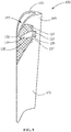
FIG. 3 schematically shows a sectional view of a nozzle with an extraction opening and a hydrophilic surface pattern, according to the present disclosure. -
FIG. 4 schematically shows a sectional view of a nozzle with extraction openings and a hydrophilic surface pattern, according to the present disclosure. -
FIG. 5 schematically shows a sectional view of a nozzle with extraction openings and hydrophilic surface patterns, according to the present disclosure. - Wherever possible, the same reference numbers will be used throughout the drawings to represent the same parts.
- Provided is at least one hydrophilic surface pattern directing surface moisture in at least one predetermined direction in a steam turbine. In some embodiments, the hydrophilic surface pattern is a laser etched nano-scale pattern creating a hydrophilic surface. In some embodiments, the hydrophilic surface pattern creates a superhydrophilic surface. Embodiments of the present disclosure, for example, in comparison to concepts failing to include one or more of the features disclosed herein, enable enhanced moisture management by enhancing moisture removal, reducing erosion caused by moisture in a steam turbine, especially in the low pressure section, or combinations thereof.
- Control of erosion in margin stage turbine buckets is desirable and often necessary. As turbine designs evolve, designers are often faced with the presence of greater amounts of moisture and the presence of new materials, some of which are difficult to protect with conventional shielding. Effectively removing moisture and controlling droplet sizes and locations improves margin bucket life and turbine aerodynamic efficiency. Turbine efficiency is positively impacted by reduced moisture and reduced erosion, as the originally-designed airfoil shape is maintained for a longer period of time. Greater efficiency in moisture removal is achieved by the use of the hydrophilic surface patterns over existing technology utilizing only slits or holes or coatings.
- The use of the hydrophilic surface patterns also permits optimization of the number, size, and/or location of extraction openings needed by directing the moisture more efficiently towards them. The optimization preferably minimizes the number and size of the extraction openings. Minimizing the size and number of extraction openings further improves the efficiency of turbine performance through the avoidance of higher vacuum levels inside the nozzles. Reducing the vacuum reduces the volume of steam pulled into the nozzles, leaving more steam available downstream to provide more power. In some embodiments, the hydrophilic surface patterns are hydrophilic or superhydrophilic laser-etched nano-scale patterns.
- A greater volume of moisture is removed from the flow stream, because the frequency of droplets escaping the extraction openings is reduced. Reducing the number of slits or holes reduces manufacturing costs. Since the number of stress risers in the nozzles, caused by the inclusion of extraction openings, may be reduced with fewer slits/holes, less expensive materials may be used for nozzle manufacture.
- In a diaphragm nozzle-based extraction system, a hydrophilic surface pattern is positioned strategically in front of an extraction opening, which serves as an extraction point, to enable enhanced attraction of the condensed moisture from a greater surface area towards the extraction point. In some embodiments, the extraction opening is a hole or a slit. This improves the volume of water that is extracted and may be used to reduce the number and size of holes or slits needed to accomplish effective reduction of erosion. The centrifugal force from the rotating rotor and buckets causes moisture deposited on the buckets to move away from the rotor and be deposited on the upper portion of the nozzles or on the casing. The hydrophilic surface pattern and extraction opening are preferably located to collect moisture away from the upper 40% of the length of the nozzle. The hydrophilic surface pattern and extraction opening are more preferably located to collect moisture away from the upper 30% of the length of the nozzle. A reduced pressure or suction applied from within the casing to the interior cavity of the nozzle removes moisture from the nozzle interior cavity collected through the extraction opening.
- In some embodiments, a hydrophilic surface pattern is positioned on a bucket to direct water downward toward the rotor and away from the casing. The centrifugal force from the rotating rotor and buckets causes moisture deposited on the buckets to move away from the rotor and toward the casing, and the hydrophilic surface pattern on the bucket serves to oppose some of that moisture movement. The hydrophilic surface pattern is preferably located to direct moisture toward the rotor from the area of the upper 40% of the length of the bucket. The hydrophilic surface pattern is more preferably located to direct moisture toward the rotor from the area of the upper 30% of the length of the bucket. The hydrophilic surface pattern may include a series of narrow patterns that also reduce the size of the droplets coming off the bucket by preventing coalescence of smaller droplets into larger droplets that cause greater erosion by impact with downstream surfaces.
- In some embodiments, a hydrophilic surface pattern is positioned on the nozzle or the casing surface near a drain in the casing to enable enhanced attraction of the condensed moisture from a greater surface area towards the drain.
- Each of the above-mentioned locations for a hydrophilic surface pattern may be used alone or in combination with any of the others.
- When introducing elements of various embodiments of the present invention, the articles "a," "an," "the," and "said" are intended to mean that there are one or more of the elements. The terms "comprising," "including," and "having" are intended to be inclusive and mean that there may be additional elements other than the listed elements.
- Systems used to generate power include, but are not limited to, steam turbines, gas turbines, and other turbine assemblies, such as steam turbines or land based aero-derivatives used for power generation. In certain applications, the power generation systems, including the turbomachinery therein (e.g., turbines, compressors, and pumps) and other machinery, may include articles that are exposed to heavy wear conditions. For example, the rotating articles may include certain power generation system components, such as steam turbine rotors or wheels or gas turbine rotors or wheels, and may operate in high heat and high revolution environments.
-
FIG. 1 schematically shows an example of asteam turbine system 100, according to the present disclosure. Thesteam turbine system 100 includes aturbine rotor 101 that is mounted rotatably about an axis ofrotation 103. Thesteam turbine system 100 includes a high pressure (HP)section 105, an intermediate pressure (IP)section 107, and a low pressure (LP)section 109, each mounted on therotor 101. WhileFIG. 1 shows one arrangement of theHP section 105, theIP section 107, and theLP section 109, the present disclosure is not so limited; any suitable arrangement of theHP section 105, theIP section 107, and/or theLP section 109 may be utilized. Each of theHP section 105, theIP section 107, and theLP section 109 includes blades or buckets 131 (seeFIG. 2 ) that are circumferentially mounted on therotor 101 in HP, IP, andLP casings HP section 105, theIP section 107, and theLP section 109, respectively. Thebuckets 131 are driven by steam fed to the respective section, where the rotation of thebuckets 131 resulting from the steam generates mechanical work. The mechanical work produced in theturbine system 100 drives anexternal load 104, such as an electrical generator, via therotor 101. - As shown in
FIG. 1 , high pressure steam is fed via highpressure steam inlets 111. The steam is exhausted from theHP section 105 at a highpressure steam outlet 113 and fed to areheater 115, in which heat is added to the steam. From thereheater 115, the steam is fed to theIP section 107 via an intermediatepressure steam inlet 117. The steam is exhausted from theIP section 107 at an intermediatepressure steam outlet 119 and fed to theLP section 109 via a lowpressure steam inlet 121. The steam is then exhausted from theLP section 109 vialow pressure outlets 123. - Each of the
HP section 105, theIP section 107, and theLP section 109 are connected along therotor 101 viacouplings 125. Thecouplings 125 may be mechanical couplings, such as bolted joints, or may be welded joints. In one embodiment, thecouplings 125 permit detachment of any of theHP section 105, theIP section 107, and/or theLP section 109 for reconfiguration, service, or maintenance. - Referring to
FIG. 2 , theLP section 109 includes theturbine rotor 101 implanted circumferentially withbuckets 131 and thecasing 130 supportingnozzles 133. Thebuckets 131 and thenozzles 133 are arranged in stages in the axial direction of theturbine rotor 101. Generally, thebuckets 131, casing 130, andnozzles 133 are constructed from materials including suitable known turbine bucket, casing, and nozzle materials, including, but not limited to, steel, stainless steel, precipitation-hardened stainless steel, aluminum, titanium, alloys thereof, or combinations thereof. TheLP section 109 includes at least oneremoval surface 134 having an area with ahydrophilic surface pattern 135 directing surface moisture in at least one predetermined direction. Thehydrophilic surface patterns 135 on thebucket 131 direct surface moisture toward therotor 101 and away from thecasing 130.Hydrophilic surface patterns 135 on thenozzle 133 are located upstream of and direct surface moisture toward theextraction openings 137 in thenozzle 133. The centrifugal force causes moisture deposited on thebucket 131 to flow away from therotor 101 before coming off thebucket 131 in droplets and to gather on the upper portions of thenozzle 133 and the wall surface of thecasing 130.Hydrophilic surface patterns 135 on the surface of thenozzle 133 and thecasing 130 direct moisture toward adrain 139 in thecasing 130. - In some embodiments, the
steam turbine system 100 is part of a power-generation system with a wet steam having a moisture content of about 10% flowing near the final stage of the low-pressure turbine because the steam temperature has decreased. - In other embodiments, the
steam turbine system 100 is part of a nuclear power plant and has a high-pressure turbine section 105 operating with wet steam because saturated steam is initially supplied. In such embodiments, thehydrophilic surface pattern 135 may be located in any stage of thesteam turbine system 100 for enhanced moisture management. - A hydrophilic surface, as used herein, is a surface having a water contact angle less than 90 degrees. The water contact angle is the angle, as measured through the water, where the water/air interface of a drop of water meets the solid surface. In some embodiments, the water contact angle of the hydrophilic surface is less than 45 degrees, alternatively less than 30 degrees, alternatively less than 20 degrees, alternatively less than 10 degrees, or any suitable combination, sub-combination, range, or sub-range thereof. A superhydrophilic surface, as used herein, is a surface having a water contact angle less than 10 degrees. In some embodiments, the water contact angle of the superhydrophilic surface is less than 5 degrees.
- A
hydrophilic surface pattern 135, as used herein, is any surface pattern formed in the surface of a material that changes the topography of the surface, rather than coating the surface, to increase the hydrophilicity of the surface such that the surface with thehydrophilic surface pattern 135 is hydrophilic. The changes to the topography may include, but are not limited to, indentations, protrusions, cavities, grooves, ridges, spheres, or rods. In some embodiments, the topography change is a micro-scale change. In some embodiments, the topography change is a nano-scale change. Any method capable of producing ahydrophilic surface pattern 135 may be applied to change the topography of the surface within the spirit of the present invention. In some embodiments, the surface with thehydrophilic surface pattern 135 is superhydrophilic. - In some embodiments, the
removal surface 134 is processed by a finishing technique prior to the laser etching. The finishing technique preferably provides theremoval surface 134 with any surface texture, up to a mirror-like surface, that improves the receptiveness of theremoval surface 134 to receive a hydrophilic surface pattern by laser etching. This preparation may include, but is not limited to, grinding, sanding, polishing, honing, electro-polishing, chemical milling, drag finishing, or any combination thereof. The processing may only be selectively needed depending on the size and depth of thehydrophilic surface pattern 135 employed. - In some embodiments, the
hydrophilic surface pattern 135 is formed by any method capable of laser-etching a pattern on thenozzle 133,bucket 131, or casing 130 to make theremoval surface 134 hydrophilic or more hydrophilic than without thehydrophilic surface pattern 135. In some embodiments, thehydrophilic surface pattern 135 makes the surface superhydrophilic. In some embodiments, the laser used to laser etch the pattern is a femtosecond laser, also known as a femto laser. In some embodiments, the femtosecond laser forms a three-dimensional pattern by laser etching the removal surface with high-energy femtosecond-long laser pulses. The laser-etched pattern may have a patterning in the micrometer to nanometer size range. - In some embodiments, the laser etching creates one or more indentations in the
removal surface 134 of the material that have a micro-rough surface of protrusions, cavities, spheres, rods, or other regularly or irregularly shaped features that increases the hydrophilicity of the surface. In some embodiments, the features have dimensions in the range of 0.5 to 100 microns, alternatively in the range of 25 to 75 microns, alternatively in the range of 40 to 60 microns, or any suitable combination, sub-combination, range, or sub-range thereof. In other embodiments, the laser etching creates one or more indentations in theremoval surface 134 of the material that have a nano-rough surface of protrusions, cavities, spheres, rods, or other irregularly shaped features that increases the hydrophilicity of theremoval surface 134. In some embodiments, the features have dimensions in the range of 1 to 500 nanometers, alternatively in the range of 100 to 400 nanometers, alternatively in the range of 200 to 300 nanometers, or any suitable combination, sub-combination, range, or sub-range thereof. - In some embodiments, laser etching is accomplished by direct laser ablation, interferometric laser ablation, near-field laser ablation, mask-projection ablation, laser-assisted chemical etching, deposition from a laser ablation plume, or plasmonic nanoablation. In some embodiments, the laser etching is accomplished using femtosecond duration laser pulses. A femtosecond duration laser pulse, as used herein, is any laser pulse having a duration in the range of 1 to 999 femtoseconds. In some embodiments, the laser pulse has a duration in the range of 100 to 750 femtoseconds. In some embodiments, the laser pulse has a duration in the range of 400 to 600 femtoseconds.
- The
hydrophilic surface pattern 135 created by the laser etching may be any regular or irregular pattern that makes theremoval surface 134 hydrophilic or more hydrophilic. In some embodiments, thehydrophilic surface pattern 135 created by the laser etching makes theremoval surface 134 superhydrophilic. In some embodiments, thehydrophilic surface pattern 135 directs moisture flow in a predetermined direction along theremoval surface 134. In some embodiments, thehydrophilic surface pattern 135 directs the moisture flow in a predetermined direction as a result of the orientation of the specific patterning of thehydrophilic surface pattern 135. In some embodiments, thehydrophilic surface pattern 135 directs the moisture flow in a predetermined direction as a result of shape and orientation of the patterned area, as the moisture tends to remain within the patterned area of the surface based on the hydrophilicity, while flowing based on movement of the component having thehydrophilic surface pattern 135 or fluid flow over the surface during operation of the steam turbine. - In some embodiments, one or more hydrophilic surface zones are created on the
diaphragm nozzle 133 such that the condensing moisture is attracted from a larger surface area of thenozzle 133 and is directed toward one ormore extraction openings 137 provided to extract an increased volume of the liquid. In some embodiments, these zones reduce the number ofcostly extraction openings 137, in the form of machined holes or slits, required to remove a predetermined amount of moisture, thereby reducing local stress risers in the nozzles caused by the machined holes or slits as well as the buckets, by reducing erosion, and enabling use of thinner wall sections or alternate materials. - Referring to
FIG. 3 , thenozzle 133 includes anozzle wall 141 having aninner surface 143, anouter surface 145, anextraction opening 137 through thenozzle wall 141 from theouter surface 145 to theinner surface 143, and ahydrophilic surface pattern 135 on aremoval surface 134 on theouter surface 145 of thenozzle wall 141 adjacent theextraction opening 137. Thehydrophilic surface pattern 135 is located upstream of and draws surface moisture toward and into theextraction opening 137. The drawn moisture then flows into theinterior cavity 147 defined by theinner surface 143 of thenozzle wall 141. Thenozzle wall 141 generally has an asymmetric shape, with the front-facing outer surface ofFIG. 3 being slightly concave in shape and the back-facing outer surface, not visible inFIG. 3 , being slightly convex in shape. Although thehydrophilic surface pattern 135 and theextraction opening 137 are shown on the concave side inFIG. 3 , a hydrophilic surface pattern and an extraction opening may alternatively or additionally be located on the convex side. - Referring to
FIG. 4 , thenozzle 133 includes a pair ofextraction openings 137 through thenozzle wall 141 from theouter surface 145 to theinner surface 143 and ahydrophilic surface pattern 135 on aremoval surface 134 on theouter surface 145 of thenozzle wall 141 adjacent theextraction openings 137. Thehydrophilic surface pattern 135 is located upstream of and draws surface moisture toward and into theextraction openings 137. The drawn moisture then flows into theinterior cavity 147 defined by theinner surface 143 of thenozzle wall 141. Although thehydrophilic surface pattern 135 and theextraction openings 137 are shown on the concave side inFIG. 4 , a hydrophilic surface pattern and an extraction opening may alternatively or additionally be located on the convex side. - Referring to
FIG. 5 , thenozzle 133 includes threeextraction openings 137 through thenozzle wall 141 from theouter surface 145 to theinner surface 143 andhydrophilic surface patterns 135 on aremoval surface 134 on theouter surface 145 of thenozzle wall 141 adjacent theextraction openings 137. Thehydrophilic surface patterns 135 are located upstream of and draw surface moisture toward and into theextraction openings 137. The drawn moisture then flows into theinterior cavity 147 defined by theinner surface 143 of thenozzle wall 141. Although thehydrophilic surface patterns 135 and theextraction openings 137 are shown on the concave side inFIG. 5 , a hydrophilic surface pattern and an extraction opening may alternatively or additionally be located on the convex side. - Although a specific size, shape, and location of the
drain 139 inFIG. 2 and specific sizes, shapes, numbers, and locations of extraction openings and specific sizes, shapes, numbers, and locations ofhydrophilic surface patterns 135 are shown inFIG. 2 through FIG. 5 , any suitable size, shape, number, or location ofdrains 139,extraction openings 137, andhydrophilic surface patterns 135 may be used to achieve a predetermined management of moisture. In some embodiments, thehydrophilic surface pattern 135 covers only a small area just in front of theextraction opening 137 to direct surface moisture near theextraction opening 137 into theextraction opening 137. In such embodiments, thehydrophilic surface pattern 135 covers only an area about equal in size to the area of theextraction opening 137, alternatively about twice the area, alternatively about three times the area, alternatively about four times the area, alternatively about five times the area, alternatively about twice to about five times the area of theextraction opening 137, or any suitable combination, sub-combination, range, or sub-range thereof. - In some embodiments, a method of forming a
steam turbine 100 for enhanced moisture management includes laser etching at least onehydrophilic surface pattern 135 on aremoval surface 134 of at least one of aturbine casing 130, at least onebucket 131, and at least onenozzle 133 of thesteam turbine 100 to direct moisture on theremoval surface 134 in a predetermined direction to enhance moisture management in thesteam turbine 100. Thesteam turbine 100 includes theturbine casing 110, aturbine rotor 101 disposed in theturbine casing 110, thebucket 131 extending from theturbine rotor 101, and thenozzle 133 supported by theturbine casing 110. In some embodiments, the method includes forming anozzle wall 141 of thenozzle 133 having aninner surface 143 and anouter surface 145 and forming at least oneextraction opening 137 through thenozzle wall 141 from theouter surface 145 to theinner surface 143, where theremoval surface 134 is located on theouter surface 145 of thenozzle wall 141 adjacent theextraction opening 137. Thehydrophilic surface pattern 135 is preferably on an upstream side of thenozzle wall 141 adjacent theextraction opening 137. The laser etching preferably includes etching the outer surface with high-energy femtosecond-long laser pulses with patterning in a 1 to 500 nanometer size range. - In some embodiments, a component in service may be removed from service and a
hydrophilic surface pattern 135 may be applied to a surface of the component. Such components may include those that previously had aremoval surface 134 with ahydrophilic surface pattern 135 or those that did not previously have aremoval surface 134 with ahydrophilic surface pattern 135. In some situations, aremoval surface 134 may lose its hydrophilicity over time during operation of asteam turbine 100 for reasons that may include, but are not limited to, damage to thehydrophilic surface pattern 135 or deposition of foreign material on thehydrophilic surface pattern 135 during operation of thesteam turbine system 100. In some embodiments, theremoval surface 134 may be made hydrophilic or more hydrophilic again during service of the component by cleaning theremoval surface 134 having thehydrophilic surface pattern 135 or laser etching a newhydrophilic surface pattern 135 on theremoval surface 134. - Although the invention has been described primarily with respect to a low pressure section of a steam turbine, the invention may be applied to any other system where moisture removal would be beneficial, including, but not limited to, a high pressure section of a steam turbine, an intermediate pressure section of a steam turbine, or a compressor section of a gas turbine.
- While the invention has been described with reference to one or more embodiments, it will be understood by those skilled in the art that various changes may be made and equivalents may be substituted for elements thereof without departing from the scope of the invention. In addition, many modifications may be made to adapt a particular situation or material to the teachings of the invention without departing from the essential scope thereof. Therefore, it is intended that the invention not be limited to the particular embodiment disclosed as the best mode contemplated for carrying out this invention, but that the invention will include all embodiments falling within the scope of the appended claims.
- Various aspects and embodiments of the present invention are defined by the following clauses:
- 1. A steam turbine comprising:
- a turbine casing;
- a turbine rotor disposed in the turbine casing;
- at least one bucket extending from the turbine rotor; and
- at least one nozzle supported by the turbine casing;
- 2. The steam turbine of clause 1, wherein the hydrophilic surface pattern is a superhydrophilic laser-etched nano-scale pattern.
- 3. The steam turbine of clause 1, wherein the nozzle comprises a nozzle wall having an inner surface, an outer surface, and at least one extraction opening through the nozzle wall from the inner surface to the outer surface, and wherein the removal surface is located on the outer surface of the nozzle wall adjacent the extraction opening to enhance moisture removal through the extraction opening.
- 4. The steam turbine of clause 3, wherein the removal surface is located on an upstream side of the nozzle wall adjacent the extraction opening.
- 5. The steam turbine of clause 3, wherein the hydrophilic surface pattern directs moisture on the removal surface toward the extraction opening.
- 6. The steam turbine of clause 3, wherein the extraction opening is a slit.
- 7. The steam turbine of clause 1, wherein the removal surface is located on the surface of the turbine casing and directs moisture toward a drain in the turbine casing.
- 8. A steam turbine nozzle comprising:
- a nozzle wall having an inner surface, an outer surface, at least one extraction opening through the nozzle wall from the outer surface to the inner surface, and
- a hydrophilic surface pattern on the outer surface of the nozzle wall adjacent the extraction opening.
- 9. The steam turbine nozzle of clause 8, wherein the hydrophilic surface pattern is a superhydrophilic laser-etched nano-scale pattern.
- 10. The steam turbine nozzle of clause 8, wherein the hydrophilic surface pattern is located on an upstream side of the nozzle wall adjacent the extraction opening.
- 11. The steam turbine nozzle of clause 8, wherein the hydrophilic surface pattern directs condensing moisture toward the extraction opening.
- 12. The steam turbine nozzle of clause 8, wherein the extraction opening is a slit.
- 13. A method of managing moisture in a steam turbine comprising:
- laser etching at least one hydrophilic surface pattern on a removal surface of at least one of a turbine casing, at least one bucket, and at least one nozzle of the steam turbine to direct moisture on the removal surface in a predetermined direction to enhance moisture management in the steam turbine, the steam turbine comprising:
- the turbine casing;
- a turbine rotor disposed in the turbine casing;
- the bucket extending from the turbine rotor; and
- the nozzle supported by the turbine casing.
- laser etching at least one hydrophilic surface pattern on a removal surface of at least one of a turbine casing, at least one bucket, and at least one nozzle of the steam turbine to direct moisture on the removal surface in a predetermined direction to enhance moisture management in the steam turbine, the steam turbine comprising:
- 14. The method of clause 13, further comprising:
- forming a nozzle wall of the nozzle having an inner surface and an outer surface; and
- forming at least one extraction opening through the nozzle wall from the outer surface to the inner surface;
- 15. The method of clause 14, wherein the removal surface is located on an upstream side of the nozzle wall adjacent the extraction opening.
- 16. The method of clause 13, wherein the hydrophilic surface pattern is a superhydrophilic laser-etched nano-scale pattern.
- 17. The method of clause 13, wherein the removal surface is located on the surface of the bucket and directs moisture away from the turbine casing.
- 18. The method of clause 13, wherein the removal surface is located on the surface of the turbine casing and directs moisture toward a drain in the turbine casing.
- 19. The method of clause 13, wherein the laser etching comprises laser etching the outer surface with high-energy femtosecond-long laser pulses with patterning in a 1 to 500 nanometer size range.
- 20. The method of clause 13 further comprising finishing the removal surface prior to laser etching.
Claims (15)
- A steam turbine (100) comprising:a turbine casing (130);a turbine rotor (101) disposed in the turbine casing (130);at least one bucket (131) extending from the turbine rotor (101); andat least one nozzle (133) supported by the turbine casing (130);wherein at least one hydrophilic surface pattern (135) on a removal surface (134) of at least one of the turbine casing (130), the bucket (131), and the nozzle (133) directs moisture on the removal surface (134) in a predetermined direction to enhance moisture management in the steam turbine (100).
- The steam turbine (100) of claim 1, wherein the hydrophilic surface pattern (135) is a superhydrophilic laser-etched nano-scale pattern.
- The steam turbine (100) of claim 1 or claim 2, wherein the nozzle (133) comprises a nozzle wall (141) having an inner surface (143), an outer surface (145), and at least one extraction opening (137) through the nozzle wall (141) from the inner surface (143) to the outer surface (145), and wherein the removal surface (134) is located on the outer surface (145) of the nozzle wall (141) adjacent the extraction opening (137) to enhance moisture removal through the extraction opening (137).
- The steam turbine (100) of claim 3, wherein the removal surface (134) is located on an upstream side of the nozzle wall (141) adjacent the extraction opening (137).
- The steam turbine (100) of claim 3, wherein the hydrophilic surface pattern (135) directs moisture on the removal surface (134) toward the extraction opening (137).
- The steam turbine (100) of any of claims 3 to 5, wherein the extraction opening (137) is a slit.
- The steam turbine (100) of claim 1, wherein the removal surface (134) is located on the surface of the turbine casing (130) and directs moisture toward a drain (139) in the turbine casing (130).
- A steam turbine nozzle (133) comprising:a nozzle wall (141) having an inner surface (143), an outer surface (145), at least one extraction opening (137) through the nozzle wall (141) from the outer surface (145) to the inner surface (143), and a hydrophilic surface pattern (135) on the outer surface (145) of the nozzle wall (141) adjacent the extraction opening (137).
- A method of managing moisture in a steam turbine (100) comprising:laser etching at least one hydrophilic surface pattern (135) on a removal surface (134) of at least one of a turbine casing (130), at least one bucket (131), and at least one nozzle (133) of the steam turbine (100) to direct moisture on the removal surface (134) in a predetermined direction to enhance moisture management in the steam turbine (100), the steam turbine (100) comprising:the turbine casing (130);a turbine rotor (101) disposed in the turbine casing (130);the bucket (131) extending from the turbine rotor (101); andthe nozzle (133) supported by the turbine casing (130).
- The method of claim 9, further comprising:forming a nozzle wall (141) of the nozzle (133) having an inner surface (143) and an outer surface (145); andforming at least one extraction opening (137) through the nozzle wall (141) from the outer surface (145) to the inner surface (143);wherein the removal surface (134) is located on the outer surface (145) of the nozzle wall (141) adjacent the extraction opening (137).
- The method of claim 9, wherein the hydrophilic surface pattern (135) is a superhydrophilic laser-etched nano-scale pattern.
- The method of claim 9, wherein the removal surface (134) is located on the surface of the bucket (131) and directs moisture away from the turbine casing (130).
- The method of claim 9, wherein the removal surface (134) is located on the surface of the turbine casing (130) and directs moisture toward a drain in the turbine casing (130).
- The method of claim 9, wherein the laser etching comprises laser etching the outer surface (145) with high-energy femtosecond-long laser pulses with patterning in a 1 to 500 nanometer size range.
- The method of claim 9 further comprising finishing the removal surface (134) prior to laser etching.
Applications Claiming Priority (1)
| Application Number | Priority Date | Filing Date | Title |
|---|---|---|---|
| US14/966,466 US10781722B2 (en) | 2015-12-11 | 2015-12-11 | Steam turbine, a steam turbine nozzle, and a method of managing moisture in a steam turbine |
Publications (2)
| Publication Number | Publication Date |
|---|---|
| EP3203041A1 true EP3203041A1 (en) | 2017-08-09 |
| EP3203041B1 EP3203041B1 (en) | 2021-08-25 |
Family
ID=57530600
Family Applications (1)
| Application Number | Title | Priority Date | Filing Date |
|---|---|---|---|
| EP16202996.1A Active EP3203041B1 (en) | 2015-12-11 | 2016-12-08 | A steam turbine, a steam turbine nozzle, and a method of managing moisture in a steam turbine |
Country Status (4)
| Country | Link |
|---|---|
| US (1) | US10781722B2 (en) |
| EP (1) | EP3203041B1 (en) |
| JP (1) | JP6931991B2 (en) |
| CN (1) | CN106988792B (en) |
Families Citing this family (10)
| Publication number | Priority date | Publication date | Assignee | Title |
|---|---|---|---|---|
| GB2524782B (en) * | 2014-04-02 | 2016-04-20 | Verderg Ltd | Turbine assembly |
| JP7179652B2 (en) * | 2019-02-27 | 2022-11-29 | 三菱重工業株式会社 | Turbine stator blades and steam turbines |
| JP7179651B2 (en) * | 2019-02-27 | 2022-11-29 | 三菱重工業株式会社 | Turbine stator blades and steam turbines |
| KR102739479B1 (en) * | 2019-12-11 | 2024-12-05 | 미츠비시 파워 가부시키가이샤 | Turbine stator, turbine stator assembly, and steam turbine |
| DE112021004233T5 (en) | 2020-08-12 | 2023-06-07 | Mitsubishi Heavy Industries, Ltd. | TURBINE STATOR BLADE AND STEAM TURBINE |
| JP7352534B2 (en) | 2020-11-25 | 2023-09-28 | 三菱重工業株式会社 | Steam turbine rotor blade, manufacturing method and modification method of steam turbine rotor blade |
| WO2023276385A1 (en) * | 2021-06-28 | 2023-01-05 | 三菱パワー株式会社 | Turbine stator vane and steam turbine |
| CN114459881A (en) * | 2022-01-29 | 2022-05-10 | 重庆邮电大学 | Super-wetting material and manufacturing method and application thereof |
| KR20250027846A (en) * | 2022-11-11 | 2025-02-27 | 미츠비시 파워 가부시키가이샤 | Blades for steam turbines, steam turbines, and methods for manufacturing blades for steam turbines |
| JP2024176436A (en) * | 2023-06-08 | 2024-12-19 | 三菱重工コンプレッサ株式会社 | Steam turbine |
Citations (12)
| Publication number | Priority date | Publication date | Assignee | Title |
|---|---|---|---|---|
| SU615240A1 (en) * | 1976-04-26 | 1978-07-15 | Московский авиационный институт им.С.Орджоникидзе | Moisture-steam turbine blade |
| SU1507991A1 (en) * | 1988-01-13 | 1989-09-15 | Комсомольский-на-Амуре политехнический институт | Blades of wet-steam turbine stage |
| DE19546008A1 (en) * | 1995-12-09 | 1997-06-12 | Abb Patent Gmbh | Turbine blade, which is intended for use in the wet steam area of pre-output and output stages of turbines |
| EP1780379A2 (en) * | 2005-10-31 | 2007-05-02 | Kabushiki Kaisha Toshiba | Steam turbine and hydrophilic coating material used therefor |
| JP2007309235A (en) * | 2006-05-19 | 2007-11-29 | Toshiba Corp | Turbine blade |
| JP2009191733A (en) * | 2008-02-14 | 2009-08-27 | Toshiba Corp | Steam turbine blade and surface reforming method thereof |
| EP2390467A1 (en) * | 2010-05-31 | 2011-11-30 | Siemens Aktiengesellschaft | Protective coating for reducing drop impact erosion |
| US20120328905A1 (en) * | 2006-09-29 | 2012-12-27 | University Of Rochester | Nanostructured materials, methods, and applications |
| EP2574729A2 (en) * | 2011-09-27 | 2013-04-03 | Siemens Aktiengesellschaft | Turbine blade and method for manufacturing a turbine blade |
| WO2013087073A2 (en) * | 2011-12-16 | 2013-06-20 | Herbert Jennissen | Substrate with a structured surface and methods for the production thereof, and methods for determining the wetting properties thereof |
| JP2013234599A (en) * | 2012-05-08 | 2013-11-21 | Toshiba Corp | Steam turbine, and moving blade of steam turbine |
| WO2015029444A1 (en) * | 2013-08-30 | 2015-03-05 | 株式会社 東芝 | Erosion resistant material and turbine blade |
Family Cites Families (9)
| Publication number | Priority date | Publication date | Assignee | Title |
|---|---|---|---|---|
| DE2128262C3 (en) * | 1971-06-07 | 1973-12-13 | Universal-Maschinenfabrik Dr. Rudolf Schieber Kg, 7081 Westhausen | Flat knitting machine with a device for keeping the knitted fabric wide |
| AU2003284210A1 (en) | 2002-10-15 | 2004-05-04 | Vast Power Systems, Inc. | Method and apparatus for mixing fluids |
| US20050056313A1 (en) | 2003-09-12 | 2005-03-17 | Hagen David L. | Method and apparatus for mixing fluids |
| US20060091123A1 (en) * | 2004-10-28 | 2006-05-04 | Hon Hai Precision Industry Co., Ltd. | Method for hydrophilic treatment of a surface of a material |
| EP2224096A1 (en) * | 2009-02-27 | 2010-09-01 | Alstom Technology Ltd | Steam turbine and method for extracting moisture from a steam turbine |
| ITMI20120010A1 (en) | 2012-01-05 | 2013-07-06 | Gen Electric | TURBINE AERODYNAMIC PROFILE IN SLIT |
| FR2990756B1 (en) | 2012-05-18 | 2014-12-26 | Ge Energy Products France Snc | METHOD FOR CREATING A COLLISION BETWEEN A CURRENT GAS AND PARTICLES AND A TARGET |
| JP5968173B2 (en) * | 2012-09-14 | 2016-08-10 | 三菱日立パワーシステムズ株式会社 | Steam turbine stationary blade and steam turbine |
| CA2928931C (en) | 2013-10-28 | 2019-03-05 | The Procter & Gamble Company | Oral care compositions for tooth desensitizing |
-
2015
- 2015-12-11 US US14/966,466 patent/US10781722B2/en not_active Expired - Fee Related
-
2016
- 2016-11-30 JP JP2016231917A patent/JP6931991B2/en not_active Expired - Fee Related
- 2016-12-08 EP EP16202996.1A patent/EP3203041B1/en active Active
- 2016-12-09 CN CN201611128465.0A patent/CN106988792B/en not_active Expired - Fee Related
Patent Citations (13)
| Publication number | Priority date | Publication date | Assignee | Title |
|---|---|---|---|---|
| SU615240A1 (en) * | 1976-04-26 | 1978-07-15 | Московский авиационный институт им.С.Орджоникидзе | Moisture-steam turbine blade |
| SU1507991A1 (en) * | 1988-01-13 | 1989-09-15 | Комсомольский-на-Амуре политехнический институт | Blades of wet-steam turbine stage |
| DE19546008A1 (en) * | 1995-12-09 | 1997-06-12 | Abb Patent Gmbh | Turbine blade, which is intended for use in the wet steam area of pre-output and output stages of turbines |
| EP1780379A2 (en) * | 2005-10-31 | 2007-05-02 | Kabushiki Kaisha Toshiba | Steam turbine and hydrophilic coating material used therefor |
| JP2007309235A (en) * | 2006-05-19 | 2007-11-29 | Toshiba Corp | Turbine blade |
| US20120328905A1 (en) * | 2006-09-29 | 2012-12-27 | University Of Rochester | Nanostructured materials, methods, and applications |
| JP2009191733A (en) * | 2008-02-14 | 2009-08-27 | Toshiba Corp | Steam turbine blade and surface reforming method thereof |
| EP2390467A1 (en) * | 2010-05-31 | 2011-11-30 | Siemens Aktiengesellschaft | Protective coating for reducing drop impact erosion |
| EP2574729A2 (en) * | 2011-09-27 | 2013-04-03 | Siemens Aktiengesellschaft | Turbine blade and method for manufacturing a turbine blade |
| WO2013087073A2 (en) * | 2011-12-16 | 2013-06-20 | Herbert Jennissen | Substrate with a structured surface and methods for the production thereof, and methods for determining the wetting properties thereof |
| JP2013234599A (en) * | 2012-05-08 | 2013-11-21 | Toshiba Corp | Steam turbine, and moving blade of steam turbine |
| WO2015029444A1 (en) * | 2013-08-30 | 2015-03-05 | 株式会社 東芝 | Erosion resistant material and turbine blade |
| EP3040363A1 (en) * | 2013-08-30 | 2016-07-06 | Kabushiki Kaisha Toshiba | Erosion resistant material and turbine blade |
Also Published As
| Publication number | Publication date |
|---|---|
| US10781722B2 (en) | 2020-09-22 |
| JP2017106451A (en) | 2017-06-15 |
| JP6931991B2 (en) | 2021-09-08 |
| CN106988792A (en) | 2017-07-28 |
| EP3203041B1 (en) | 2021-08-25 |
| CN106988792B (en) | 2021-04-13 |
| US20170167301A1 (en) | 2017-06-15 |
Similar Documents
| Publication | Publication Date | Title |
|---|---|---|
| EP3203041B1 (en) | A steam turbine, a steam turbine nozzle, and a method of managing moisture in a steam turbine | |
| CN1222684C (en) | Steam turbine and blades thereof | |
| EP2708699B1 (en) | Steam turbine stationary blade and steam turbine | |
| CN1971001B (en) | Steam turbine and hydrophilic coating material used therefor | |
| EP2592229A2 (en) | Film hole trench | |
| JP2011117451A (en) | System for reducing effect of erosion on component | |
| EP2740898B1 (en) | An airfoil and a cooling arrangement for an airfoil platform | |
| EP3152403B1 (en) | Turbine blisk and method of manufacturing thereof | |
| US20150110617A1 (en) | Turbine airfoil including tip fillet | |
| EP2823174A1 (en) | Erosion resistant and hydrophobic article | |
| EP2876264B1 (en) | Stationary blade for a steam turbine | |
| KR101578176B1 (en) | Steam turbine | |
| JP2017020443A (en) | Nozzle for steam turbine and steam turbine provided with the nozzle | |
| EP3765713B1 (en) | Mistuning of turbine blades with one or more internal cavities | |
| JP2007309235A (en) | Turbine blade | |
| EP3211102A1 (en) | Method of treatment, turbine component, and turbine system | |
| US11739648B2 (en) | Steam turbine rotor blade and manufacturing method and remodeling method of steam turbine rotor blade | |
| WO2014096840A1 (en) | An aerofoil structure with tip portion cutting edges | |
| JP7714794B2 (en) | Fluid machine blade with abradable coating surface and notched blade tip, and method for manufacturing the same | |
| KR20230023783A (en) | Turbine stators, and steam turbines | |
| Smith et al. | Erosion of steam turbine blade shield materials | |
| CN114542193B (en) | Steam turbine rotor blade | |
| JPH062503A (en) | Moisture separation structure for steam turbine stationary blade | |
| RU2208682C1 (en) | Steam turbine mean pressure cylinder | |
| JP2025066360A (en) | Shield member and turbine blade |
Legal Events
| Date | Code | Title | Description |
|---|---|---|---|
| PUAI | Public reference made under article 153(3) epc to a published international application that has entered the european phase |
Free format text: ORIGINAL CODE: 0009012 |
|
| STAA | Information on the status of an ep patent application or granted ep patent |
Free format text: STATUS: THE APPLICATION HAS BEEN PUBLISHED |
|
| AK | Designated contracting states |
Kind code of ref document: A1 Designated state(s): AL AT BE BG CH CY CZ DE DK EE ES FI FR GB GR HR HU IE IS IT LI LT LU LV MC MK MT NL NO PL PT RO RS SE SI SK SM TR |
|
| AX | Request for extension of the european patent |
Extension state: BA ME |
|
| STAA | Information on the status of an ep patent application or granted ep patent |
Free format text: STATUS: REQUEST FOR EXAMINATION WAS MADE |
|
| 17P | Request for examination filed |
Effective date: 20180209 |
|
| RBV | Designated contracting states (corrected) |
Designated state(s): AL AT BE BG CH CY CZ DE DK EE ES FI FR GB GR HR HU IE IS IT LI LT LU LV MC MK MT NL NO PL PT RO RS SE SI SK SM TR |
|
| RIC1 | Information provided on ipc code assigned before grant |
Ipc: B23K 26/36 20140101ALN20201222BHEP Ipc: B23K 26/402 20140101ALN20201222BHEP Ipc: F01D 25/32 20060101AFI20201222BHEP |
|
| GRAP | Despatch of communication of intention to grant a patent |
Free format text: ORIGINAL CODE: EPIDOSNIGR1 |
|
| STAA | Information on the status of an ep patent application or granted ep patent |
Free format text: STATUS: GRANT OF PATENT IS INTENDED |
|
| RIC1 | Information provided on ipc code assigned before grant |
Ipc: B23K 26/36 20140101ALN20210223BHEP Ipc: F01D 25/32 20060101AFI20210223BHEP Ipc: B23K 26/402 20140101ALN20210223BHEP |
|
| INTG | Intention to grant announced |
Effective date: 20210329 |
|
| GRAS | Grant fee paid |
Free format text: ORIGINAL CODE: EPIDOSNIGR3 |
|
| GRAA | (expected) grant |
Free format text: ORIGINAL CODE: 0009210 |
|
| STAA | Information on the status of an ep patent application or granted ep patent |
Free format text: STATUS: THE PATENT HAS BEEN GRANTED |
|
| AK | Designated contracting states |
Kind code of ref document: B1 Designated state(s): AL AT BE BG CH CY CZ DE DK EE ES FI FR GB GR HR HU IE IS IT LI LT LU LV MC MK MT NL NO PL PT RO RS SE SI SK SM TR |
|
| REG | Reference to a national code |
Ref country code: CH Ref legal event code: EP |
|
| REG | Reference to a national code |
Ref country code: DE Ref legal event code: R096 Ref document number: 602016062664 Country of ref document: DE |
|
| REG | Reference to a national code |
Ref country code: IE Ref legal event code: FG4D Ref country code: AT Ref legal event code: REF Ref document number: 1424001 Country of ref document: AT Kind code of ref document: T Effective date: 20210915 |
|
| REG | Reference to a national code |
Ref country code: LT Ref legal event code: MG9D |
|
| REG | Reference to a national code |
Ref country code: NL Ref legal event code: MP Effective date: 20210825 |
|
| REG | Reference to a national code |
Ref country code: AT Ref legal event code: MK05 Ref document number: 1424001 Country of ref document: AT Kind code of ref document: T Effective date: 20210825 |
|
| PG25 | Lapsed in a contracting state [announced via postgrant information from national office to epo] |
Ref country code: RS Free format text: LAPSE BECAUSE OF FAILURE TO SUBMIT A TRANSLATION OF THE DESCRIPTION OR TO PAY THE FEE WITHIN THE PRESCRIBED TIME-LIMIT Effective date: 20210825 Ref country code: SE Free format text: LAPSE BECAUSE OF FAILURE TO SUBMIT A TRANSLATION OF THE DESCRIPTION OR TO PAY THE FEE WITHIN THE PRESCRIBED TIME-LIMIT Effective date: 20210825 Ref country code: HR Free format text: LAPSE BECAUSE OF FAILURE TO SUBMIT A TRANSLATION OF THE DESCRIPTION OR TO PAY THE FEE WITHIN THE PRESCRIBED TIME-LIMIT Effective date: 20210825 Ref country code: LT Free format text: LAPSE BECAUSE OF FAILURE TO SUBMIT A TRANSLATION OF THE DESCRIPTION OR TO PAY THE FEE WITHIN THE PRESCRIBED TIME-LIMIT Effective date: 20210825 Ref country code: AT Free format text: LAPSE BECAUSE OF FAILURE TO SUBMIT A TRANSLATION OF THE DESCRIPTION OR TO PAY THE FEE WITHIN THE PRESCRIBED TIME-LIMIT Effective date: 20210825 Ref country code: BG Free format text: LAPSE BECAUSE OF FAILURE TO SUBMIT A TRANSLATION OF THE DESCRIPTION OR TO PAY THE FEE WITHIN THE PRESCRIBED TIME-LIMIT Effective date: 20211125 Ref country code: PT Free format text: LAPSE BECAUSE OF FAILURE TO SUBMIT A TRANSLATION OF THE DESCRIPTION OR TO PAY THE FEE WITHIN THE PRESCRIBED TIME-LIMIT Effective date: 20211227 Ref country code: NO Free format text: LAPSE BECAUSE OF FAILURE TO SUBMIT A TRANSLATION OF THE DESCRIPTION OR TO PAY THE FEE WITHIN THE PRESCRIBED TIME-LIMIT Effective date: 20211125 Ref country code: FI Free format text: LAPSE BECAUSE OF FAILURE TO SUBMIT A TRANSLATION OF THE DESCRIPTION OR TO PAY THE FEE WITHIN THE PRESCRIBED TIME-LIMIT Effective date: 20210825 Ref country code: ES Free format text: LAPSE BECAUSE OF FAILURE TO SUBMIT A TRANSLATION OF THE DESCRIPTION OR TO PAY THE FEE WITHIN THE PRESCRIBED TIME-LIMIT Effective date: 20210825 |
|
| PGFP | Annual fee paid to national office [announced via postgrant information from national office to epo] |
Ref country code: DE Payment date: 20211117 Year of fee payment: 6 |
|
| PG25 | Lapsed in a contracting state [announced via postgrant information from national office to epo] |
Ref country code: PL Free format text: LAPSE BECAUSE OF FAILURE TO SUBMIT A TRANSLATION OF THE DESCRIPTION OR TO PAY THE FEE WITHIN THE PRESCRIBED TIME-LIMIT Effective date: 20210825 Ref country code: LV Free format text: LAPSE BECAUSE OF FAILURE TO SUBMIT A TRANSLATION OF THE DESCRIPTION OR TO PAY THE FEE WITHIN THE PRESCRIBED TIME-LIMIT Effective date: 20210825 Ref country code: GR Free format text: LAPSE BECAUSE OF FAILURE TO SUBMIT A TRANSLATION OF THE DESCRIPTION OR TO PAY THE FEE WITHIN THE PRESCRIBED TIME-LIMIT Effective date: 20211126 |
|
| PGFP | Annual fee paid to national office [announced via postgrant information from national office to epo] |
Ref country code: IT Payment date: 20211117 Year of fee payment: 6 |
|
| PG25 | Lapsed in a contracting state [announced via postgrant information from national office to epo] |
Ref country code: NL Free format text: LAPSE BECAUSE OF FAILURE TO SUBMIT A TRANSLATION OF THE DESCRIPTION OR TO PAY THE FEE WITHIN THE PRESCRIBED TIME-LIMIT Effective date: 20210825 |
|
| PG25 | Lapsed in a contracting state [announced via postgrant information from national office to epo] |
Ref country code: DK Free format text: LAPSE BECAUSE OF FAILURE TO SUBMIT A TRANSLATION OF THE DESCRIPTION OR TO PAY THE FEE WITHIN THE PRESCRIBED TIME-LIMIT Effective date: 20210825 |
|
| REG | Reference to a national code |
Ref country code: DE Ref legal event code: R097 Ref document number: 602016062664 Country of ref document: DE |
|
| PG25 | Lapsed in a contracting state [announced via postgrant information from national office to epo] |
Ref country code: SM Free format text: LAPSE BECAUSE OF FAILURE TO SUBMIT A TRANSLATION OF THE DESCRIPTION OR TO PAY THE FEE WITHIN THE PRESCRIBED TIME-LIMIT Effective date: 20210825 Ref country code: SK Free format text: LAPSE BECAUSE OF FAILURE TO SUBMIT A TRANSLATION OF THE DESCRIPTION OR TO PAY THE FEE WITHIN THE PRESCRIBED TIME-LIMIT Effective date: 20210825 Ref country code: RO Free format text: LAPSE BECAUSE OF FAILURE TO SUBMIT A TRANSLATION OF THE DESCRIPTION OR TO PAY THE FEE WITHIN THE PRESCRIBED TIME-LIMIT Effective date: 20210825 Ref country code: EE Free format text: LAPSE BECAUSE OF FAILURE TO SUBMIT A TRANSLATION OF THE DESCRIPTION OR TO PAY THE FEE WITHIN THE PRESCRIBED TIME-LIMIT Effective date: 20210825 Ref country code: CZ Free format text: LAPSE BECAUSE OF FAILURE TO SUBMIT A TRANSLATION OF THE DESCRIPTION OR TO PAY THE FEE WITHIN THE PRESCRIBED TIME-LIMIT Effective date: 20210825 Ref country code: AL Free format text: LAPSE BECAUSE OF FAILURE TO SUBMIT A TRANSLATION OF THE DESCRIPTION OR TO PAY THE FEE WITHIN THE PRESCRIBED TIME-LIMIT Effective date: 20210825 |
|
| PLBE | No opposition filed within time limit |
Free format text: ORIGINAL CODE: 0009261 |
|
| STAA | Information on the status of an ep patent application or granted ep patent |
Free format text: STATUS: NO OPPOSITION FILED WITHIN TIME LIMIT |
|
| PG25 | Lapsed in a contracting state [announced via postgrant information from national office to epo] |
Ref country code: MC Free format text: LAPSE BECAUSE OF FAILURE TO SUBMIT A TRANSLATION OF THE DESCRIPTION OR TO PAY THE FEE WITHIN THE PRESCRIBED TIME-LIMIT Effective date: 20210825 |
|
| REG | Reference to a national code |
Ref country code: CH Ref legal event code: PL |
|
| 26N | No opposition filed |
Effective date: 20220527 |
|
| GBPC | Gb: european patent ceased through non-payment of renewal fee |
Effective date: 20211208 |
|
| PG25 | Lapsed in a contracting state [announced via postgrant information from national office to epo] |
Ref country code: SI Free format text: LAPSE BECAUSE OF FAILURE TO SUBMIT A TRANSLATION OF THE DESCRIPTION OR TO PAY THE FEE WITHIN THE PRESCRIBED TIME-LIMIT Effective date: 20210825 |
|
| REG | Reference to a national code |
Ref country code: BE Ref legal event code: MM Effective date: 20211231 |
|
| PG25 | Lapsed in a contracting state [announced via postgrant information from national office to epo] |
Ref country code: LU Free format text: LAPSE BECAUSE OF NON-PAYMENT OF DUE FEES Effective date: 20211208 Ref country code: IE Free format text: LAPSE BECAUSE OF NON-PAYMENT OF DUE FEES Effective date: 20211208 Ref country code: GB Free format text: LAPSE BECAUSE OF NON-PAYMENT OF DUE FEES Effective date: 20211208 |
|
| PG25 | Lapsed in a contracting state [announced via postgrant information from national office to epo] |
Ref country code: FR Free format text: LAPSE BECAUSE OF NON-PAYMENT OF DUE FEES Effective date: 20211231 Ref country code: BE Free format text: LAPSE BECAUSE OF NON-PAYMENT OF DUE FEES Effective date: 20211231 |
|
| PG25 | Lapsed in a contracting state [announced via postgrant information from national office to epo] |
Ref country code: LI Free format text: LAPSE BECAUSE OF NON-PAYMENT OF DUE FEES Effective date: 20211231 Ref country code: CH Free format text: LAPSE BECAUSE OF NON-PAYMENT OF DUE FEES Effective date: 20211231 |
|
| PG25 | Lapsed in a contracting state [announced via postgrant information from national office to epo] |
Ref country code: HU Free format text: LAPSE BECAUSE OF FAILURE TO SUBMIT A TRANSLATION OF THE DESCRIPTION OR TO PAY THE FEE WITHIN THE PRESCRIBED TIME-LIMIT; INVALID AB INITIO Effective date: 20161208 |
|
| PG25 | Lapsed in a contracting state [announced via postgrant information from national office to epo] |
Ref country code: CY Free format text: LAPSE BECAUSE OF FAILURE TO SUBMIT A TRANSLATION OF THE DESCRIPTION OR TO PAY THE FEE WITHIN THE PRESCRIBED TIME-LIMIT Effective date: 20210825 |
|
| REG | Reference to a national code |
Ref country code: DE Ref legal event code: R119 Ref document number: 602016062664 Country of ref document: DE |
|
| PG25 | Lapsed in a contracting state [announced via postgrant information from national office to epo] |
Ref country code: DE Free format text: LAPSE BECAUSE OF NON-PAYMENT OF DUE FEES Effective date: 20230701 |
|
| PG25 | Lapsed in a contracting state [announced via postgrant information from national office to epo] |
Ref country code: IT Free format text: LAPSE BECAUSE OF NON-PAYMENT OF DUE FEES Effective date: 20221208 |
|
| PG25 | Lapsed in a contracting state [announced via postgrant information from national office to epo] |
Ref country code: MK Free format text: LAPSE BECAUSE OF FAILURE TO SUBMIT A TRANSLATION OF THE DESCRIPTION OR TO PAY THE FEE WITHIN THE PRESCRIBED TIME-LIMIT Effective date: 20210825 |
|
| PG25 | Lapsed in a contracting state [announced via postgrant information from national office to epo] |
Ref country code: TR Free format text: LAPSE BECAUSE OF FAILURE TO SUBMIT A TRANSLATION OF THE DESCRIPTION OR TO PAY THE FEE WITHIN THE PRESCRIBED TIME-LIMIT Effective date: 20210825 |
|
| PG25 | Lapsed in a contracting state [announced via postgrant information from national office to epo] |
Ref country code: MT Free format text: LAPSE BECAUSE OF FAILURE TO SUBMIT A TRANSLATION OF THE DESCRIPTION OR TO PAY THE FEE WITHIN THE PRESCRIBED TIME-LIMIT Effective date: 20210825 |