EP3203034A1 - Thermally biased valve and anti-icing system - Google Patents
Thermally biased valve and anti-icing system Download PDFInfo
- Publication number
- EP3203034A1 EP3203034A1 EP17154687.2A EP17154687A EP3203034A1 EP 3203034 A1 EP3203034 A1 EP 3203034A1 EP 17154687 A EP17154687 A EP 17154687A EP 3203034 A1 EP3203034 A1 EP 3203034A1
- Authority
- EP
- European Patent Office
- Prior art keywords
- valve
- fluid
- bimetallic
- pressure
- biasing element
- Prior art date
- Legal status (The legal status is an assumption and is not a legal conclusion. Google has not performed a legal analysis and makes no representation as to the accuracy of the status listed.)
- Pending
Links
- 239000000463 material Substances 0.000 claims abstract description 24
- 239000012530 fluid Substances 0.000 claims description 58
- 238000000034 method Methods 0.000 claims description 24
- 230000004044 response Effects 0.000 claims description 16
- 230000003247 decreasing effect Effects 0.000 claims description 9
- 230000008859 change Effects 0.000 claims description 4
- 230000033228 biological regulation Effects 0.000 description 18
- 230000007423 decrease Effects 0.000 description 8
- 239000007769 metal material Substances 0.000 description 7
- 230000009467 reduction Effects 0.000 description 5
- 239000000956 alloy Substances 0.000 description 2
- 229910045601 alloy Inorganic materials 0.000 description 2
- 230000006835 compression Effects 0.000 description 2
- 238000007906 compression Methods 0.000 description 2
- 230000004907 flux Effects 0.000 description 2
- 238000012986 modification Methods 0.000 description 2
- 230000004048 modification Effects 0.000 description 2
- 230000002411 adverse Effects 0.000 description 1
- 238000001816 cooling Methods 0.000 description 1
- 230000001419 dependent effect Effects 0.000 description 1
- 230000037361 pathway Effects 0.000 description 1
- 230000001141 propulsive effect Effects 0.000 description 1
- 230000008439 repair process Effects 0.000 description 1
- 238000000926 separation method Methods 0.000 description 1
Images


Classifications
-
- B—PERFORMING OPERATIONS; TRANSPORTING
- B64—AIRCRAFT; AVIATION; COSMONAUTICS
- B64D—EQUIPMENT FOR FITTING IN OR TO AIRCRAFT; FLIGHT SUITS; PARACHUTES; ARRANGEMENT OR MOUNTING OF POWER PLANTS OR PROPULSION TRANSMISSIONS IN AIRCRAFT
- B64D15/00—De-icing or preventing icing on exterior surfaces of aircraft
- B64D15/02—De-icing or preventing icing on exterior surfaces of aircraft by ducted hot gas or liquid
- B64D15/04—Hot gas application
-
- F—MECHANICAL ENGINEERING; LIGHTING; HEATING; WEAPONS; BLASTING
- F01—MACHINES OR ENGINES IN GENERAL; ENGINE PLANTS IN GENERAL; STEAM ENGINES
- F01D—NON-POSITIVE DISPLACEMENT MACHINES OR ENGINES, e.g. STEAM TURBINES
- F01D17/00—Regulating or controlling by varying flow
- F01D17/02—Arrangement of sensing elements
- F01D17/08—Arrangement of sensing elements responsive to condition of working-fluid, e.g. pressure
- F01D17/085—Arrangement of sensing elements responsive to condition of working-fluid, e.g. pressure to temperature
-
- F—MECHANICAL ENGINEERING; LIGHTING; HEATING; WEAPONS; BLASTING
- F02—COMBUSTION ENGINES; HOT-GAS OR COMBUSTION-PRODUCT ENGINE PLANTS
- F02C—GAS-TURBINE PLANTS; AIR INTAKES FOR JET-PROPULSION PLANTS; CONTROLLING FUEL SUPPLY IN AIR-BREATHING JET-PROPULSION PLANTS
- F02C7/00—Features, components parts, details or accessories, not provided for in, or of interest apart form groups F02C1/00 - F02C6/00; Air intakes for jet-propulsion plants
- F02C7/04—Air intakes for gas-turbine plants or jet-propulsion plants
- F02C7/047—Heating to prevent icing
-
- F—MECHANICAL ENGINEERING; LIGHTING; HEATING; WEAPONS; BLASTING
- F16—ENGINEERING ELEMENTS AND UNITS; GENERAL MEASURES FOR PRODUCING AND MAINTAINING EFFECTIVE FUNCTIONING OF MACHINES OR INSTALLATIONS; THERMAL INSULATION IN GENERAL
- F16K—VALVES; TAPS; COCKS; ACTUATING-FLOATS; DEVICES FOR VENTING OR AERATING
- F16K17/00—Safety valves; Equalising valves, e.g. pressure relief valves
- F16K17/003—Safety valves; Equalising valves, e.g. pressure relief valves reacting to pressure and temperature
-
- F—MECHANICAL ENGINEERING; LIGHTING; HEATING; WEAPONS; BLASTING
- F16—ENGINEERING ELEMENTS AND UNITS; GENERAL MEASURES FOR PRODUCING AND MAINTAINING EFFECTIVE FUNCTIONING OF MACHINES OR INSTALLATIONS; THERMAL INSULATION IN GENERAL
- F16K—VALVES; TAPS; COCKS; ACTUATING-FLOATS; DEVICES FOR VENTING OR AERATING
- F16K31/00—Actuating devices; Operating means; Releasing devices
- F16K31/002—Actuating devices; Operating means; Releasing devices actuated by temperature variation
-
- G—PHYSICS
- G05—CONTROLLING; REGULATING
- G05D—SYSTEMS FOR CONTROLLING OR REGULATING NON-ELECTRIC VARIABLES
- G05D23/00—Control of temperature
- G05D23/01—Control of temperature without auxiliary power
- G05D23/02—Control of temperature without auxiliary power with sensing element expanding and contracting in response to changes of temperature
- G05D23/08—Control of temperature without auxiliary power with sensing element expanding and contracting in response to changes of temperature with bimetallic element
-
- G—PHYSICS
- G05—CONTROLLING; REGULATING
- G05D—SYSTEMS FOR CONTROLLING OR REGULATING NON-ELECTRIC VARIABLES
- G05D7/00—Control of flow
- G05D7/01—Control of flow without auxiliary power
-
- B—PERFORMING OPERATIONS; TRANSPORTING
- B64—AIRCRAFT; AVIATION; COSMONAUTICS
- B64D—EQUIPMENT FOR FITTING IN OR TO AIRCRAFT; FLIGHT SUITS; PARACHUTES; ARRANGEMENT OR MOUNTING OF POWER PLANTS OR PROPULSION TRANSMISSIONS IN AIRCRAFT
- B64D33/00—Arrangement in aircraft of power plant parts or auxiliaries not otherwise provided for
- B64D33/02—Arrangement in aircraft of power plant parts or auxiliaries not otherwise provided for of combustion air intakes
- B64D2033/0233—Arrangement in aircraft of power plant parts or auxiliaries not otherwise provided for of combustion air intakes comprising de-icing means
-
- F—MECHANICAL ENGINEERING; LIGHTING; HEATING; WEAPONS; BLASTING
- F05—INDEXING SCHEMES RELATING TO ENGINES OR PUMPS IN VARIOUS SUBCLASSES OF CLASSES F01-F04
- F05D—INDEXING SCHEME FOR ASPECTS RELATING TO NON-POSITIVE-DISPLACEMENT MACHINES OR ENGINES, GAS-TURBINES OR JET-PROPULSION PLANTS
- F05D2270/00—Control
- F05D2270/30—Control parameters, e.g. input parameters
- F05D2270/313—Air temperature
-
- F—MECHANICAL ENGINEERING; LIGHTING; HEATING; WEAPONS; BLASTING
- F05—INDEXING SCHEMES RELATING TO ENGINES OR PUMPS IN VARIOUS SUBCLASSES OF CLASSES F01-F04
- F05D—INDEXING SCHEME FOR ASPECTS RELATING TO NON-POSITIVE-DISPLACEMENT MACHINES OR ENGINES, GAS-TURBINES OR JET-PROPULSION PLANTS
- F05D2300/00—Materials; Properties thereof
- F05D2300/50—Intrinsic material properties or characteristics
- F05D2300/502—Thermal properties
- F05D2300/5021—Expansivity
- F05D2300/50212—Expansivity dissimilar
Definitions
- the present disclosure relates generally to pressure regulation systems, and more particularly to thermally responsive pressure valves used in anti-icing systems for aircraft.
- a valve includes an inlet, an outlet, and a biasing element.
- the biasing element includes a first spring element, a second spring element, and a valve element.
- the second spring element includes at least one bimetallic disk including a first and second material.
- the first material includes a first coefficient of linear thermal expansion
- the second material includes a second coefficient of linear thermal expansion different than the first coefficient of linear thermal expansion.
- the valve element is disposed on an end of the first spring element.
- a method of adjusting a valve includes directing a fluid into a first valve. Fluid is passed over a biasing element in the first valve. Thermal energy is transferred either from the fluid to at least one bimetallic disk of the biasing element or to the fluid from the at least one bimetallic disk. The curvature of the at least one bimetallic disk is altered in response to a change in temperature of the fluid. A spring force of the biasing element is changed as a function of the altered curvature of the at least one bimetallic disk. A rate of pressure of the fluid exiting the first valve is changed as a function of the changed spring force of the biasing element.
- a fluid pressure regulation system includes a first valve, second valve, and an anti-icing system for a nacelle inlet of an aircraft engine.
- the first valve includes an inlet, an outlet, and a biasing element.
- the biasing element includes a first spring element, a second spring element, and a valve element.
- the second spring element includes at least one curved bimetallic disk including first and second metallic materials.
- the first metallic material is on a concave side of the at least one curved bimetallic disk.
- the second metallic material is on a convex side of the at least one curved bimetallic disk.
- the valve element is disposed on an end of the first spring element.
- the anti-icing system is fluidly connected to the second valve.
- FIG. 1 is a cross-sectional view of gas turbine engine 10, in a two-spool turbofan configuration for use as a propulsion engine on an aircraft.
- low spool 12 includes low pressure compressor (“LPC”) 14 and low pressure turbine (“LPT”) 16, rotationally coupled via low pressure shaft 18.
- High spool 20 includes high pressure compressor (“HPC”) 22 and high pressure turbine (“HPT”) 24, rotationally coupled via high pressure shaft 26.
- High spool 20 is coaxially oriented about low spool 12, along engine centerline (or turbine axis) C L , with combustor 28 positioned in flow series between high pressure compressor 22 and high pressure turbine 24.
- Nacelle 30 is oriented about the forward end of gas turbine engine 10.
- Fan casing 32 extends along on the radially inner surface of nacelle 30, from propulsion fan 34 to fan exit guide vane 36.
- Propulsion fan 34 is rotationally coupled to low spool 12 via fan shaft 38, generating propulsive flow F P through fan duct (or bypass duct) 40.
- fan drive gear system 42 couples fan shaft 38 to low spool 12 at low pressure shaft 18, providing independent fan speed control for reduced noise and improved operating efficiency.
- Nacelle 30 extends forward of the gas turbine engine 10 and defines inlet 44 for incoming fluid.
- Nacelle 30 includes inner barrel 46, outer barrel 48, bulkhead 50, and inlet shell 52.
- Inner barrel 46 defines radially outer flow surface 54 for a portion of the flowpath of gas turbine engine 10.
- Outer barrel 48 defines outer flow surface 56 for the external medium flowing about gas turbine engine 10.
- a radial separation between inner barrel 46 and outer barrel 48 defines annular chamber 58 there between.
- Inlet shell 52 is the leading edge for nacelle 30.
- Inlet shell 52 and bulkhead 50 bound annular shell cavity 60.
- Fluid pressure regulation system 62 is fluidly connected to HPC 22 and extends into annular chamber 58.
- Anti-icing system 64 is positioned within nacelle 30 and transfers fluid, in this example bleed air, into annular shell cavity 52.
- Fluid pressure regulation system 62 includes valve assembly 66 which can include a variety of valves and flow regulators to control the flow of bleed air through fluid pressure regulation system 62 (as will be discussed with respect to the remaining figures).
- FIG. 2 is a cross-sectional view of pressure regulation system 68.
- Pressure regulation system 68 includes first valve 70 and second valve 72.
- First valve 70 includes housing 74 with inlet 76 and ports 104.
- First valve 70 contains biasing element 80 and valve element 82.
- Biasing element 80 includes first spring element 84 and second spring element 86.
- First spring element 84 can be a coil spring or another suitable biasing member.
- Second spring element 86 can be made up of one or more bimetallic disks 102.
- First valve 70 also includes port 104 to transport fluid from inside first valve 70 to an ambient environment outside of first valve 70.
- Second valve 72 includes housing 88, inlet 90, outlet 92, internal chamber 94, and valve element 96.
- Inlet 90 provides an opening through which flow F B enters into second valve 72
- outlet 92 provides an opening through which flow F B exits second valve 72.
- Internal chamber 94 includes chamber inlet 106 and contains valve element 96.
- Second valve 72 is configured such that as a pressure inside of internal chamber 94 changes, valve element 96 actuates along a linear pathway in response the change in pressure in internal chamber 94. The positioning of valve element 96 regulates an amount of flow F B exiting from outlet 92 by controlling an effective area that flow F B passes through as it travels through second valve 72, past valve element 96, and through outlet 92.
- First valve 70 and second valve 72 are fluidly connected by line 98.
- Line 98 can be a single passage that fluidly connects port 100 of housing 88 with inlet 76 of first valve 70.
- a portion of flow F B of the fluid flowing through second valve 72 is diverted through line 98 and into first valve 70.
- biasing element 80 regulates the amount of flow F B that enters into first valve 70.
- flow F B flows through ports 104, out of first valve 70, and into an ambient environment outside of first valve 70 (and outside of second valve 72).
- a curvature of bimetallic disks 102 is set to provide a desired compressive force onto bimetallic disks 102.
- flow F B of the engine bleed air is directed into first valve 70 and passed over biasing element 80 and bimetallic disks 102.
- flow F B of the bleed air is passed over second spring element 86, thermal energy is transferred to bimetallic disks 102.
- the curvature of bimetallic disks 102 is altered, and in this example the curvature of bimetallic disks 102 is reduced which decreases the height of second spring element 86, causing a decrease in the compression force in biasing element 80.
- adjusting second valve 72 includes actuating valve element 96 disposed within the second valve, which results in a reduction in the pressure of flow F B exiting out of outlet 92.
- pressure regulation system 68 includes transferring thermal energy from bimetallic disks 102 to flow F B .
- the curvature of bimetallic disks 102 is altered, and in this example the curvature of bimetallic disks 102 is increased which increases the height of second spring element 86 causing an increase in the compressive force in biasing element 80.
- the increase in height of second spring element 86 results in changing a rate of pressure of flow F B exiting first valve 70 as a function of the changed spring force of biasing element 80, and in this example a decreased rate of pressure of flow F B exiting first valve 70.
- a lower amount of flow F B exiting first valve 70 adjusts second valve 72 in response to the decrease in the rate of pressure of flow F B transferred from first valve 70.
- adjusting second valve 72 includes actuating valve element 96 disposed within the second valve, which results in an increase in the pressure of flow F B exiting out of outlet 92.
- valve element 96 actuates to the right of FIG. 2 in response to the decrease in pressure inside internal chamber 94.
- second valve 72 becomes more closed such that a rate of flow F B out of outlet 92 is decreased.
- the volume of flow F B exiting out of internal chamber 94 decreases, which increases the amount of pressure in internal chamber 94.
- a linear force is applied to valve element 96 and valve element 96 actuates to the left of FIG. 2 .
- Pressure regulation system 68 is an example of an open-loop pressure regulation system with a direct-acting design which ports bleed air flow F B to an ambient environment after flow F B exits first valve 70.
- Flow F B of the fluid is transferred from second valve 72 to nacelle 30, which includes anti-icing system 64, of gas turbine engine 10. Thermal energy is then transferred from flow F B to nacelle 30 through anti-icing system 64 and the build-up of ice on nacelle 30 is reduced in response to transferring thermal energy from flow F B to nacelle 30.
- a lower pressure of flow F B exiting out of outlet 92 results in less flow F B of bleed air to anti-icing system 64 and a lower temperature of inlet 44 of nacelle 30.
- FIG. 3 is a cross-sectional view of bimetallic disk 108.
- Bimetallic disk 108 includes first layer 110 on concave side S concave of bimetallic disk 108 and second layer 112 on convex side S convex of bimetallic disk 108.
- First layer 110 and second layer 112 are bonded together.
- Bimetallic disk 108 includes two layers, but can also include more or less layers. Additionally, first layer 110 and second layer 112 can include different curvatures, thicknesses, lengths, and sizes.
- Bimetallic disk 108 includes one or more disks including two different materials each with a different coefficient of linear thermal expansion.
- a first material of first layer 110 includes a first alloy with a first rate of thermal expansion and a second material of second layer 112 includes a second alloy with a second rate of thermal expansion less than the first rate of thermal expansion of the first material.
- the materials and quantity of layers of bimetallic disk 108 can be selected to provide a tailorable spring constant for first valve 70 in FIG. 2 .
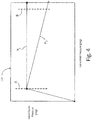
- FIG. 4 shows graph 114 of valve outlet pressure as a function of valve inlet pressure of pressure regulation system 68 shown in FIG. 2 .
- valve inlet pressure and valve outlet pressure increase until valve outlet pressure achieves regulation set-point A.
- valve inlet pressure In a system without a temperature biased valve assembly, further increases to the valve inlet pressure result in a constant outlet pressure P 1 as indicated by the zero slope of the line between set-point A and set-point B. Without a reduction in valve outlet pressure P 1 , the corresponding nacelle inlet temperature continues to increase as valve inlet pressure is increased between set-point A and set-point B potentially causing damage to the nacelle of a gas turbine engine that does not include a temperature biased bleed air assembly.
- valve outlet pressure P 2 reaches set-point A, further increases to the valve inlet pressure result in a reduced valve outlet pressure P 2 as indicated by the negative slope of the line between set-point A and set-point B.
- valve outlet pressure P 2 causing a decrease in flow and reduced heat flux, the corresponding nacelle inlet temperature is maintained at a set value as valve inlet pressure is increased between set-point A and set-point B.
- An example valve outlet pressure P 2 value for set-point A includes a pressure of approximately 45 psi (310 kpa) and an example for set-point B includes a pressure of approximately 30 psi (207 kpa).
- Example ranges for the axes of graph 114 include 0-350 psi (0-2,413 kpa) along the independent (e.g. horizontal axis) and 0-60 psi (0-414 kpa) along the dependent (e.g. vertical axis) with regards to valve outlet pressure.
- An example nacelle inlet temperature value at set-points A and B for P 2 include a temperature of approximately 400° F (204° C).
- a example range of nacelle inlet temperatures is 32°-800° F (0°-427° C) with regards to nacelle inlet temperature.
- the line segments representing valve outlet pressure P 2 can include varying slopes and/or curvilinear data points.
- a valve can include an inlet, an outlet, and/or a biasing element.
- the biasing element can include a first spring element, a second spring element, a plate, and a valve element.
- the second spring element can include at least one bimetallic disk which can include a first and second material.
- the first material can include a first coefficient of linear thermal expansion
- the second material can include a second coefficient of linear thermal expansion that can be different than the first coefficient of linear thermal expansion.
- the valve element can be disposed on an end of the first spring element.
- valve of the preceding paragraph can optionally include, additionally and/or alternatively, any one or more of the following features, configurations and/or additional components:
- a method of adjusting a valve can include directing a fluid into a first valve. Fluid can be passed over a biasing element in the first valve. Thermal energy can be transferred either from the fluid to at least one bimetallic disk of the biasing element or to the fluid from the at least one bimetallic disk. The curvature of the at least one bimetallic disk can be altered in response to a change in temperature of the fluid. A spring force of the biasing element can be changed as a function of the altered curvature of the at least one bimetallic disk. A rate of pressure of the fluid exiting the first valve can be changed as a function of the changed spring force of the biasing element.
- the method of the preceding paragraph can optionally include, additionally and/or alternatively, any one or more of the following features, configurations and/or additional components:
- a fluid pressure regulation system which the Applicant expressly reserves the right to claim independently, can include a first valve, second valve, and an anti-icing system for a nacelle inlet of an aircraft engine.
- the first valve can include an inlet, an outlet, and a biasing element.
- the biasing element can include a first spring element, a second spring element, and a valve element.
- the second spring element can include at least one curved bimetallic disk including first and second metallic materials.
- the first metallic material can be on a concave side of the at least one curved bimetallic disk.
- the second metallic material can be on a convex side of the at least one curved bimetallic disk.
- the first metallic material can have a first coefficient of linear thermal expansion greater than a second coefficient of linear thermal expansion of the second material.
- the valve element can be disposed on a second end of the biasing element.
- the screw can be connected to at least one of the biasing element and the first valve.
- the anti-icing system can be fluidly connected to the second valve.
- the second spring element can comprise a plurality of curved bimetallic disks.
- the plurality of curved bimetallic disks can comprise curved bimetallic disks facing in opposite directions.
- the second valve can include a valve element.
Landscapes
- Engineering & Computer Science (AREA)
- General Engineering & Computer Science (AREA)
- Mechanical Engineering (AREA)
- Chemical & Material Sciences (AREA)
- Combustion & Propulsion (AREA)
- Physics & Mathematics (AREA)
- General Physics & Mathematics (AREA)
- Automation & Control Theory (AREA)
- Aviation & Aerospace Engineering (AREA)
- Temperature-Responsive Valves (AREA)
- Safety Valves (AREA)
Abstract
Description
- The present disclosure relates generally to pressure regulation systems, and more particularly to thermally responsive pressure valves used in anti-icing systems for aircraft.
- Operation of aircraft engines in adverse weather conditions or at high altitudes can sometimes lead to ice forming on the exposed surfaces of the engine nacelle inlet. The build-up of ice on a nacelle surrounding the engine limits the quantity of air being fed to the engine. This reduction in inlet airflow can result in a reduction of power output, efficiency and/or cooling capacity of the engine. Engine inlet anti-icing systems commonly employ a thermal source, such as hot air bled from the engine core, which is applied to the nacelle inlet to prevent ice build-up on the external surfaces thereof.
- Another concern with aircraft engines is the useful life of the aircraft engine and components. The build-up of ice near the inlet of the engine may lead to large pieces of ice breaking loose from the inlet and flowing into the gas turbine engine. Ice flowing into and through the engine may damage components within the engine, such as the blades, and components attached to the nacelle, such as inlet acoustic panels. The damaged components may then require repair or replacement.
- Current anti-icing systems include valves that do not compensate for increases in bleed air temperature with increasing bleed pressure and as a result, delivered heat flux which is a function of flow times bleed air temperature can result in damage to the nacelle.
- A valve includes an inlet, an outlet, and a biasing element. The biasing element includes a first spring element, a second spring element, and a valve element. The second spring element includes at least one bimetallic disk including a first and second material. The first material includes a first coefficient of linear thermal expansion, and the second material includes a second coefficient of linear thermal expansion different than the first coefficient of linear thermal expansion. The valve element is disposed on an end of the first spring element.
- A method of adjusting a valve includes directing a fluid into a first valve. Fluid is passed over a biasing element in the first valve. Thermal energy is transferred either from the fluid to at least one bimetallic disk of the biasing element or to the fluid from the at least one bimetallic disk. The curvature of the at least one bimetallic disk is altered in response to a change in temperature of the fluid. A spring force of the biasing element is changed as a function of the altered curvature of the at least one bimetallic disk. A rate of pressure of the fluid exiting the first valve is changed as a function of the changed spring force of the biasing element.
- A fluid pressure regulation system includes a first valve, second valve, and an anti-icing system for a nacelle inlet of an aircraft engine. The first valve includes an inlet, an outlet, and a biasing element. The biasing element includes a first spring element, a second spring element, and a valve element. The second spring element includes at least one curved bimetallic disk including first and second metallic materials. The first metallic material is on a concave side of the at least one curved bimetallic disk. The second metallic material is on a convex side of the at least one curved bimetallic disk. The valve element is disposed on an end of the first spring element. The anti-icing system is fluidly connected to the second valve.
- The present summary is provided only by way of example, and not limitation. Other aspects of the present disclosure will be appreciated in view of the entirety of the present disclosure, including the entire text, claims and accompanying figures.
-
- FIG. 1
- is a cross-sectional view of a gas turbine engine.
- FIG. 2
- is a cross-sectional view of a direct acting pressure regulation valve.
- FIG. 3
- is a cross-sectional view of a bimetallic disk.
- FIG. 4
- is a graph of valve outlet pressure as a function of valve inlet pressure.
- While the above-identified figures set forth embodiments of the present invention, other embodiments are also contemplated, as noted in the discussion. In all cases, this disclosure presents the invention by way of representation and not limitation. It should be understood that numerous other modifications and embodiments can be devised by those skilled in the art, which fall within the scope and spirit of the principles of the invention. The figures may not be drawn to scale, and applications and embodiments of the present invention may include features, steps and/or components not specifically shown in the drawings.
-
FIG. 1 is a cross-sectional view ofgas turbine engine 10, in a two-spool turbofan configuration for use as a propulsion engine on an aircraft. As shown in the figure,low spool 12 includes low pressure compressor ("LPC") 14 and low pressure turbine ("LPT") 16, rotationally coupled vialow pressure shaft 18.High spool 20 includes high pressure compressor ("HPC") 22 and high pressure turbine ("HPT") 24, rotationally coupled viahigh pressure shaft 26.High spool 20 is coaxially oriented aboutlow spool 12, along engine centerline (or turbine axis) CL, withcombustor 28 positioned in flow series betweenhigh pressure compressor 22 andhigh pressure turbine 24. - Nacelle 30 is oriented about the forward end of
gas turbine engine 10.Fan casing 32 extends along on the radially inner surface ofnacelle 30, frompropulsion fan 34 to fan exit guide vane 36.Propulsion fan 34 is rotationally coupled tolow spool 12 viafan shaft 38, generating propulsive flow FP through fan duct (or bypass duct) 40. In advanced engine designs, fandrive gear system 42couples fan shaft 38 tolow spool 12 atlow pressure shaft 18, providing independent fan speed control for reduced noise and improved operating efficiency. - Nacelle 30 extends forward of the
gas turbine engine 10 and definesinlet 44 for incoming fluid. Nacelle 30 includesinner barrel 46,outer barrel 48,bulkhead 50, andinlet shell 52.Inner barrel 46 defines radiallyouter flow surface 54 for a portion of the flowpath ofgas turbine engine 10.Outer barrel 48 definesouter flow surface 56 for the external medium flowing aboutgas turbine engine 10. A radial separation betweeninner barrel 46 andouter barrel 48 definesannular chamber 58 there between.Inlet shell 52 is the leading edge fornacelle 30.Inlet shell 52 andbulkhead 50 bound annular shell cavity 60. - Fluid
pressure regulation system 62 is fluidly connected to HPC 22 and extends intoannular chamber 58.Anti-icing system 64 is positioned withinnacelle 30 and transfers fluid, in this example bleed air, intoannular shell cavity 52. Fluidpressure regulation system 62 includesvalve assembly 66 which can include a variety of valves and flow regulators to control the flow of bleed air through fluid pressure regulation system 62 (as will be discussed with respect to the remaining figures). -
FIG. 2 is a cross-sectional view of pressure regulation system 68. Pressure regulation system 68 includesfirst valve 70 andsecond valve 72.First valve 70 includeshousing 74 withinlet 76 andports 104.First valve 70 contains biasingelement 80 andvalve element 82. Biasingelement 80 includesfirst spring element 84 andsecond spring element 86.First spring element 84 can be a coil spring or another suitable biasing member.Second spring element 86 can be made up of one or morebimetallic disks 102.First valve 70 also includesport 104 to transport fluid from insidefirst valve 70 to an ambient environment outside offirst valve 70. -
Second valve 72 includeshousing 88, inlet 90,outlet 92,internal chamber 94, andvalve element 96. Inlet 90 provides an opening through which flow FB enters intosecond valve 72, whileoutlet 92 provides an opening through which flow FB exitssecond valve 72.Internal chamber 94 includeschamber inlet 106 and containsvalve element 96.Second valve 72 is configured such that as a pressure inside ofinternal chamber 94 changes,valve element 96 actuates along a linear pathway in response the change in pressure ininternal chamber 94. The positioning ofvalve element 96 regulates an amount of flow FB exiting fromoutlet 92 by controlling an effective area that flow FB passes through as it travels throughsecond valve 72,past valve element 96, and throughoutlet 92. -
First valve 70 andsecond valve 72 are fluidly connected byline 98.Line 98 can be a single passage that fluidly connectsport 100 ofhousing 88 withinlet 76 offirst valve 70. During operation of pressure regulation system 68, a portion of flow FB of the fluid flowing throughsecond valve 72 is diverted throughline 98 and intofirst valve 70. As flow FB entersfirst valve 70, biasingelement 80 regulates the amount of flow FB that enters intofirst valve 70. As flow FB flows throughfirst valve 70, flow FB flows throughports 104, out offirst valve 70, and into an ambient environment outside of first valve 70 (and outside of second valve 72). - Before operation of
gas turbine engine 10 begins, a curvature ofbimetallic disks 102 is set to provide a desired compressive force ontobimetallic disks 102. During engine operation, flow FB of the engine bleed air is directed intofirst valve 70 and passed over biasingelement 80 andbimetallic disks 102. As flow FB of the bleed air is passed oversecond spring element 86, thermal energy is transferred tobimetallic disks 102. As thermal energy is transferred tobimetallic disks 102, the curvature ofbimetallic disks 102 is altered, and in this example the curvature ofbimetallic disks 102 is reduced which decreases the height ofsecond spring element 86, causing a decrease in the compression force in biasingelement 80. The decrease in compression force in biasingelement 80 results in changing a rate of pressure of flow FB exitingfirst valve 70 as a function of the changed spring force of biasingelement 80, and in this example an increased rate of pressure of flow FB exitingfirst valve 70. A higher amount of flow FB exitingfirst valve 70 adjustssecond valve 72 in response to the increase in the rate of pressure of flow FB transferred fromfirst valve 70. Specifically, adjustingsecond valve 72 includesactuating valve element 96 disposed within the second valve, which results in a reduction in the pressure of flow FB exiting out ofoutlet 92. - Another example of pressure regulation system 68 includes transferring thermal energy from
bimetallic disks 102 to flow FB. In such an example, as thermal energy is transferred frombimetallic disks 102, the curvature ofbimetallic disks 102 is altered, and in this example the curvature ofbimetallic disks 102 is increased which increases the height ofsecond spring element 86 causing an increase in the compressive force in biasingelement 80. The increase in height ofsecond spring element 86 results in changing a rate of pressure of flow FB exitingfirst valve 70 as a function of the changed spring force of biasingelement 80, and in this example a decreased rate of pressure of flow FB exitingfirst valve 70. A lower amount of flow FB exitingfirst valve 70 adjustssecond valve 72 in response to the decrease in the rate of pressure of flow FB transferred fromfirst valve 70. Specifically, adjustingsecond valve 72 includesactuating valve element 96 disposed within the second valve, which results in an increase in the pressure of flow FB exiting out ofoutlet 92. - As a rate of flow FB through and out of
first valve 70 is increased, the pressure inside ofinternal chamber 94 is decreased, andvalve element 96 actuates to the right ofFIG. 2 in response to the decrease in pressure insideinternal chamber 94. Asvalve element 96 actuates to the right ofFIG. 2 ,second valve 72 becomes more closed such that a rate of flow FB out ofoutlet 92 is decreased. As a rate of flow FB through and out offirst valve 70 decreases, the volume of flow FB exiting out ofinternal chamber 94 decreases, which increases the amount of pressure ininternal chamber 94. As the amount of pressure ininternal chamber 94 increases, a linear force is applied tovalve element 96 andvalve element 96 actuates to the left ofFIG. 2 . Asvalve element 96 actuates to the left ofFIG. 2 ,second valve 72 becomes more open, such that a rate of flow FB out ofoutlet 92 is increased. Pressure regulation system 68 is an example of an open-loop pressure regulation system with a direct-acting design which ports bleed air flow FB to an ambient environment after flow FB exitsfirst valve 70. - Flow FB of the fluid is transferred from
second valve 72 tonacelle 30, which includesanti-icing system 64, ofgas turbine engine 10. Thermal energy is then transferred from flow FB to nacelle 30 throughanti-icing system 64 and the build-up of ice onnacelle 30 is reduced in response to transferring thermal energy from flow FB to nacelle 30. For example, a lower pressure of flow FB exiting out ofoutlet 92 results in less flow FB of bleed air toanti-icing system 64 and a lower temperature ofinlet 44 ofnacelle 30. -
FIG. 3 is a cross-sectional view ofbimetallic disk 108.Bimetallic disk 108 includesfirst layer 110 on concave side Sconcave ofbimetallic disk 108 andsecond layer 112 on convex side Sconvex ofbimetallic disk 108.First layer 110 andsecond layer 112 are bonded together.Bimetallic disk 108 includes two layers, but can also include more or less layers. Additionally,first layer 110 andsecond layer 112 can include different curvatures, thicknesses, lengths, and sizes. -
Bimetallic disk 108 includes one or more disks including two different materials each with a different coefficient of linear thermal expansion. A first material offirst layer 110 includes a first alloy with a first rate of thermal expansion and a second material ofsecond layer 112 includes a second alloy with a second rate of thermal expansion less than the first rate of thermal expansion of the first material. The materials and quantity of layers ofbimetallic disk 108 can be selected to provide a tailorable spring constant forfirst valve 70 inFIG. 2 . -
FIG. 4 showsgraph 114 of valve outlet pressure as a function of valve inlet pressure of pressure regulation system 68 shown inFIG. 2 . During engine operation, as the engine bleed air temperature increases, valve inlet pressure and valve outlet pressure increase until valve outlet pressure achieves regulation set-point A. - In a system without a temperature biased valve assembly, further increases to the valve inlet pressure result in a constant outlet pressure P1 as indicated by the zero slope of the line between set-point A and set-point B. Without a reduction in valve outlet pressure P1, the corresponding nacelle inlet temperature continues to increase as valve inlet pressure is increased between set-point A and set-point B potentially causing damage to the nacelle of a gas turbine engine that does not include a temperature biased bleed air assembly.
- In a system with a temperature biased valve assembly, such as in pressure regulation system 68, once valve outlet pressure P2 reaches set-point A, further increases to the valve inlet pressure result in a reduced valve outlet pressure P2 as indicated by the negative slope of the line between set-point A and set-point B. With a reduction in valve outlet pressure P2, causing a decrease in flow and reduced heat flux, the corresponding nacelle inlet temperature is maintained at a set value as valve inlet pressure is increased between set-point A and set-point B.
- An example valve outlet pressure P2 value for set-point A includes a pressure of approximately 45 psi (310 kpa) and an example for set-point B includes a pressure of approximately 30 psi (207 kpa). Example ranges for the axes of
graph 114 include 0-350 psi (0-2,413 kpa) along the independent (e.g. horizontal axis) and 0-60 psi (0-414 kpa) along the dependent (e.g. vertical axis) with regards to valve outlet pressure. An example nacelle inlet temperature value at set-points A and B for P2 include a temperature of approximately 400° F (204° C). A example range of nacelle inlet temperatures is 32°-800° F (0°-427° C) with regards to nacelle inlet temperature. - Additionally, as an example, the line segments representing valve outlet pressure P2 can include varying slopes and/or curvilinear data points.
- The following are non-exclusive descriptions of possible embodiments of the present invention.
- A valve can include an inlet, an outlet, and/or a biasing element. The biasing element can include a first spring element, a second spring element, a plate, and a valve element. The second spring element can include at least one bimetallic disk which can include a first and second material. The first material can include a first coefficient of linear thermal expansion, and the second material can include a second coefficient of linear thermal expansion that can be different than the first coefficient of linear thermal expansion. The valve element can be disposed on an end of the first spring element.
- The valve of the preceding paragraph can optionally include, additionally and/or alternatively, any one or more of the following features, configurations and/or additional components:
- a further embodiment of the foregoing valve, wherein the first material is disposed on a concave side of each of the at least one bimetallic disk and the second material is disposed on the convex side of the at least one bimetallic disk;
- a further embodiment of the foregoing valves, wherein the first coefficient of linear thermal expansion is greater than the second coefficient of linear thermal expansion;
- a further embodiment of the foregoing valves, wherein the at least one bimetallic disk can include an adjustable curvature;
- a further embodiment of the foregoing valves, wherein the valve includes at least one port to transport fluid from inside the valve to outside the valve;
- a further embodiment of the foregoing valves, wherein the valve can be fluidly connected to a nacelle of a gas turbine engine;
- a further embodiment of the foregoing valves, wherein the second spring element comprises a plurality of curved bimetallic disks; and/or
- a further embodiment of the foregoing valves, wherein the plurality of curved bimetallic disks comprise curved bimetallic disks facing in opposite directions.
- A method of adjusting a valve can include directing a fluid into a first valve. Fluid can be passed over a biasing element in the first valve. Thermal energy can be transferred either from the fluid to at least one bimetallic disk of the biasing element or to the fluid from the at least one bimetallic disk. The curvature of the at least one bimetallic disk can be altered in response to a change in temperature of the fluid. A spring force of the biasing element can be changed as a function of the altered curvature of the at least one bimetallic disk. A rate of pressure of the fluid exiting the first valve can be changed as a function of the changed spring force of the biasing element.
- The method of the preceding paragraph can optionally include, additionally and/or alternatively, any one or more of the following features, configurations and/or additional components:
- a further embodiment of the foregoing method can further comprise transferring thermal energy from the fluid to each of the bimetallic disks, decreasing the curvature of each of the bimetallic disks, decreasing the spring force of the biasing element, and increasing the rate of pressure of the fluid exiting the first valve;
- a further embodiment of the foregoing methods can further comprise transferring thermal energy to the fluid from each of the bimetallic disks, increasing the curvature of each of the bimetallic disks, increasing the spring force of the biasing element, and decreasing the rate of pressure of the fluid exiting the first valve;
- a further embodiment of the foregoing methods can further comprise transferring fluid from a second valve to the first valve, adjusting the second valve in response to the rate of pressure of the fluid exiting the first valve, and altering a flow of the fluid out of the second valve as a function of the adjusted second valve;
- a further embodiment of any of the foregoing methods, wherein adjusting the second valve can further comprise actuating a valve element disposed within the second valve;
- a further embodiment of the foregoing methods can further comprise transferring fluid from the second valve to a nacelle of an aircraft engine, and transferring thermal energy from the fluid to the nacelle; and/or
- a further embodiment of the foregoing methods can further comprise reducing the build-up of ice on the nacelle in response to transferring thermal energy from the fluid; and/or
- a further embodiment of the foregoing methods can further comprise transferring fluid out of the first valve, adjusting a pressure in an internal chamber of a second valve in response to the changed rate of pressure of the fluid exiting the first valve, adjusting the second valve in response to the adjusted pressure in the internal chamber of the second valve, and altering a flow of the fluid out of the second valve as a function of the adjusted second valve.
- A fluid pressure regulation system, which the Applicant expressly reserves the right to claim independently, can include a first valve, second valve, and an anti-icing system for a nacelle inlet of an aircraft engine. The first valve can include an inlet, an outlet, and a biasing element. The biasing element can include a first spring element, a second spring element, and a valve element. The second spring element can include at least one curved bimetallic disk including first and second metallic materials. The first metallic material can be on a concave side of the at least one curved bimetallic disk. The second metallic material can be on a convex side of the at least one curved bimetallic disk. The first metallic material can have a first coefficient of linear thermal expansion greater than a second coefficient of linear thermal expansion of the second material. The valve element can be disposed on a second end of the biasing element. The screw can be connected to at least one of the biasing element and the first valve. The anti-icing system can be fluidly connected to the second valve.
- In an embodiment of the foregoing fluid pressure regulation system, the second spring element can comprise a plurality of curved bimetallic disks.
- The plurality of curved bimetallic disks can comprise curved bimetallic disks facing in opposite directions.
- In a further embodiment of any of the foregoing fluid pressure regulation systems, the second valve can include a valve element.
- While the invention has been described with reference to an exemplary embodiment(s), it will be understood by those skilled in the art that various changes may be made and equivalents may be substituted for elements thereof without departing from the scope of the invention. In addition, many modifications may be made to adapt a particular situation or material to the teachings of the invention without departing from the essential scope thereof. Therefore, it is intended that the invention not be limited to the particular embodiment(s) disclosed, but that the invention will include all embodiments falling within the scope of the appended claims.
Claims (15)
- A valve (70) comprising:an inlet (76);an outlet (92); anda biasing element (80), and wherein the biasing element (80) comprises:a first spring element (84);a second spring element (86) comprising at least one bimetallic disk (102;108), wherein the at least one bimetallic disk (102;108) comprises a first material and a second material, further wherein the first material has a first coefficient of linear thermal expansion different from a second coefficient of linear thermal expansion of the second material; anda valve element (82) disposed on an end of the first spring element (84).
- The valve of claim 1, wherein the first material is disposed on a concave side of each of the at least one bimetallic disk (102;108) and the second material is disposed on the convex side of the at least one bimetallic disk (102;108).
- The valve of claim 1 or 2, wherein the first coefficient of linear thermal expansion is greater than the second coefficient of linear thermal expansion.
- The valve of any preceding claim, wherein the at least one bimetallic disk (102;108) includes an adjustable curvature.
- The valve of any preceding claim, wherein the valve includes at least one port (104) to transport fluid from inside the valve to outside the valve.
- The valve of any preceding claim, wherein the valve is fluidly connected to a nacelle (30) of a gas turbine engine (10).
- The valve of any preceding claim, wherein the second spring element (86) comprises a plurality of curved bimetallic disks (102;108).
- The valve of claim 7, wherein the plurality of curved bimetallic disks (102;108) comprise curved bimetallic disks (102;108) facing in opposite directions.
- A method of adjusting a first valve (70), the method comprising:directing a fluid into the first valve (70);passing the fluid over a biasing element (80) in the first valve (70);transferring thermal energy either from the fluid to at least one bimetallic disk (102;108) disposed in the biasing element (80) or to the fluid from the at least one bimetallic disk (102;108);altering the curvature of the at least one bimetallic disk (102;108) in response to a change in temperature of the fluid;changing a spring force of the biasing element (80) as a function of the altered curvature of the at least one bimetallic disk (102;108); andchanging a rate of pressure of the fluid exiting the first valve (70) as a function of the changed spring force of the biasing element (80).
- The method of claim 9, the method further comprising:transferring thermal energy from the fluid to each of the bimetallic disks (102;108);decreasing the curvature of each of the bimetallic disks (102;108);decreasing the spring force of the biasing element (80); andincreasing the rate of pressure of the fluid exiting the first valve (70).
- The method of claim 9, the method further comprising:transferring thermal energy to the fluid from each of the bimetallic disks (102;108);increasing the curvature of each of the bimetallic disks (102;108);increasing the spring force of the biasing element (80); anddecreasing the rate of pressure of the fluid exiting the first valve (70).
- The method of any of claims 9 to 11, the method further comprising:transferring fluid from a second valve (72) to the first valve (70);adjusting the second valve (72) in response to the rate of pressure of the fluid exiting the first valve (70); andaltering a flow of the fluid out of the second valve (72) as a function of the adjusted second valve (72).
- The method of any of claims 9 to 11, the method further comprising:transferring fluid out of the first valve (70);adjusting a pressure in an internal chamber (94) of a second valve (72) in response to the changed rate of pressure of the fluid exiting the first valve (70);adjusting the second valve (72) in response to the adjusted pressure in the internal chamber (94) of the second valve (72); andaltering a flow of the fluid out of the second valve (72) as a function of the adjusted second valve (72).
- The method of claim 12 or 13, wherein adjusting the second (72) valve further comprises actuating a valve element (96) disposed within the second valve (72).
- The method of any of claims 12 to 14, the method further comprising:transferring fluid from the second valve (72) to a nacelle (30) of an aircraft engine; andtransferring thermal energy from the fluid to the nacelle (30), the method further optionally comprising:reducing the build-up of ice on the nacelle (30) in response to transferring thermal energy from the fluid.
Applications Claiming Priority (1)
| Application Number | Priority Date | Filing Date | Title |
|---|---|---|---|
| US15/017,159 US10384786B2 (en) | 2016-02-05 | 2016-02-05 | Thermally biased valve and anti-icing system |
Publications (1)
| Publication Number | Publication Date |
|---|---|
| EP3203034A1 true EP3203034A1 (en) | 2017-08-09 |
Family
ID=57965792
Family Applications (1)
| Application Number | Title | Priority Date | Filing Date |
|---|---|---|---|
| EP17154687.2A Pending EP3203034A1 (en) | 2016-02-05 | 2017-02-03 | Thermally biased valve and anti-icing system |
Country Status (2)
| Country | Link |
|---|---|
| US (1) | US10384786B2 (en) |
| EP (1) | EP3203034A1 (en) |
Families Citing this family (3)
| Publication number | Priority date | Publication date | Assignee | Title |
|---|---|---|---|---|
| US20170267360A1 (en) * | 2016-03-18 | 2017-09-21 | Rohr, Inc. | Thermal management system for deicing aircraft with temperature based flow restrictor |
| US12366421B2 (en) | 2023-02-09 | 2025-07-22 | Hamilton Sundstrand Corporation | Thermally adaptive flow conduit |
| EP4506600A1 (en) | 2023-08-10 | 2025-02-12 | Microtecnica S.r.l. | Thermal compensated pressure relief valve using shape memory materials for high temperature application |
Citations (7)
| Publication number | Priority date | Publication date | Assignee | Title |
|---|---|---|---|---|
| US4249695A (en) * | 1979-12-12 | 1981-02-10 | Emerson Electric Co. (H & H Prod. Div) | Thermally actuated modulating valve, and assemblies and systems utilizing the same for providing temperature controlled heated water |
| US4358925A (en) * | 1980-07-15 | 1982-11-16 | The United States Of America As Represented By The Secretary Of The Air Force | Temperature sensing assembly |
| EP0106781A1 (en) * | 1982-09-23 | 1984-04-25 | United Technologies Corporation | Minimization of pressure drop variation in flow controllers |
| US4473999A (en) * | 1981-11-16 | 1984-10-02 | Lucas Industries Limited | Fuel control system for a gas turbine engine |
| US5156332A (en) * | 1991-09-24 | 1992-10-20 | United Technologies Corporation | Pressure regulating flow control apparatus |
| WO1999035385A1 (en) * | 1998-01-08 | 1999-07-15 | United Technologies Corporation | Bi-level hydraulic pressurizing system |
| US20150034767A1 (en) * | 2013-07-30 | 2015-02-05 | Airbus Operations S.A.S. | Method For Regulating The De-Icing Of A Leading Edge Of An Aircraft And Device For Its Implementation |
Family Cites Families (14)
| Publication number | Priority date | Publication date | Assignee | Title |
|---|---|---|---|---|
| US3741610A (en) | 1970-07-13 | 1973-06-26 | H Holland | Variable ratio proportioning device |
| GB1345351A (en) | 1971-03-19 | 1974-01-30 | Pott L | Rotary valve controlled internal combustion engines |
| US4106510A (en) | 1976-11-26 | 1978-08-15 | Hakim Company Limited | Servo valve |
| DE2903561C2 (en) | 1979-01-31 | 1983-06-30 | Pierburg Gmbh & Co Kg, 4040 Neuss | Device for the delayed actuation of a valve or switch |
| US4688745A (en) | 1986-01-24 | 1987-08-25 | Rohr Industries, Inc. | Swirl anti-ice system |
| US5257498A (en) | 1992-04-23 | 1993-11-02 | United Technologies Corporation | Efficient anti-ice exhaust vent |
| US7131612B2 (en) | 2003-07-29 | 2006-11-07 | Pratt & Whitney Canada Corp. | Nacelle inlet lip anti-icing with engine oil |
| ES2308384T3 (en) | 2005-07-01 | 2008-12-01 | Saab Ab | DEVICE AND ANTI-ICE SYSTEM FOR AIRCRAFT UNDERSTANDING SUCH DEVICE. |
| DE102006031330B4 (en) | 2005-07-14 | 2014-03-20 | Goodrich Corp. | An ice-susceptible portion of an aircraft, in particular an aircraft engine cell inlet lip, comprising an ice protection system, aircraft engine having such an inlet lip, and a method of protecting such inlet lip from icing |
| US9169779B2 (en) | 2007-10-09 | 2015-10-27 | United Technologies Corp. | Systems and methods for altering inlet airflow of gas turbine engines |
| US7959109B2 (en) | 2008-07-02 | 2011-06-14 | The Boeing Company | Dual valve apparatus for aircraft engine ice protection and related methods |
| US8047252B2 (en) | 2008-12-19 | 2011-11-01 | United Technologies Corporation | Modular component pressure application fixture |
| US8572985B2 (en) | 2009-06-26 | 2013-11-05 | Pratt & Whitney Canada Corp. | Air filtration system for gas turbine engine pneumatic system |
| EP3084179B1 (en) | 2013-12-16 | 2020-02-05 | United Technologies Corporation | Fan nacelle inlet flow control |
-
2016
- 2016-02-05 US US15/017,159 patent/US10384786B2/en active Active
-
2017
- 2017-02-03 EP EP17154687.2A patent/EP3203034A1/en active Pending
Patent Citations (7)
| Publication number | Priority date | Publication date | Assignee | Title |
|---|---|---|---|---|
| US4249695A (en) * | 1979-12-12 | 1981-02-10 | Emerson Electric Co. (H & H Prod. Div) | Thermally actuated modulating valve, and assemblies and systems utilizing the same for providing temperature controlled heated water |
| US4358925A (en) * | 1980-07-15 | 1982-11-16 | The United States Of America As Represented By The Secretary Of The Air Force | Temperature sensing assembly |
| US4473999A (en) * | 1981-11-16 | 1984-10-02 | Lucas Industries Limited | Fuel control system for a gas turbine engine |
| EP0106781A1 (en) * | 1982-09-23 | 1984-04-25 | United Technologies Corporation | Minimization of pressure drop variation in flow controllers |
| US5156332A (en) * | 1991-09-24 | 1992-10-20 | United Technologies Corporation | Pressure regulating flow control apparatus |
| WO1999035385A1 (en) * | 1998-01-08 | 1999-07-15 | United Technologies Corporation | Bi-level hydraulic pressurizing system |
| US20150034767A1 (en) * | 2013-07-30 | 2015-02-05 | Airbus Operations S.A.S. | Method For Regulating The De-Icing Of A Leading Edge Of An Aircraft And Device For Its Implementation |
Also Published As
| Publication number | Publication date |
|---|---|
| US10384786B2 (en) | 2019-08-20 |
| US20170225791A1 (en) | 2017-08-10 |
Similar Documents
| Publication | Publication Date | Title |
|---|---|---|
| US9849992B2 (en) | Inline pressure regulating valve assembly with inlet pressure bias | |
| US11384690B2 (en) | System and method of reducing post-shutdown engine temperatures | |
| JP6165413B2 (en) | Environmental control system supply precooler bypass | |
| US8955794B2 (en) | Bleed air systems for use with aircrafts and related methods | |
| EP2829706B1 (en) | Bleed air systems for use with aircrafts and related methods | |
| EP3219957B1 (en) | Thermal management system for deicing aircraft with temperature based flow restrictor | |
| EP3092388B1 (en) | Cross-stream heat exchanger | |
| EP3354572B1 (en) | Aircraft bleed system | |
| EP2096271A2 (en) | System and method for passive cooling of gas turbine engine control components | |
| EP3106647A1 (en) | Temperature-modulated recuperated gas turbine engine | |
| JPH0220804B2 (en) | ||
| EP3211182A1 (en) | Active hpc clearance control | |
| EP3608228B1 (en) | Powered pre-cooler fan assembly | |
| US10436148B2 (en) | Convergent-divergent nozzle | |
| EP3203034A1 (en) | Thermally biased valve and anti-icing system | |
| EP2708702A2 (en) | Pressurization of Generator | |
| US11060454B2 (en) | Method of regulating air pressure in anti-icing system | |
| EP4477861A1 (en) | Gas turbine engine with air/oil cooler having an airflow control baffle | |
| US6779967B2 (en) | Device for air mass flow control | |
| US20230011409A1 (en) | Method of managing thermal energy in a propulsion system | |
| EP3839233B1 (en) | Gas turbine engine and operation method | |
| CN119593873A (en) | Method of operating a turbine engine having an exhaust system |
Legal Events
| Date | Code | Title | Description |
|---|---|---|---|
| PUAI | Public reference made under article 153(3) epc to a published international application that has entered the european phase |
Free format text: ORIGINAL CODE: 0009012 |
|
| STAA | Information on the status of an ep patent application or granted ep patent |
Free format text: STATUS: THE APPLICATION HAS BEEN PUBLISHED |
|
| AK | Designated contracting states |
Kind code of ref document: A1 Designated state(s): AL AT BE BG CH CY CZ DE DK EE ES FI FR GB GR HR HU IE IS IT LI LT LU LV MC MK MT NL NO PL PT RO RS SE SI SK SM TR |
|
| AX | Request for extension of the european patent |
Extension state: BA ME |
|
| STAA | Information on the status of an ep patent application or granted ep patent |
Free format text: STATUS: REQUEST FOR EXAMINATION WAS MADE |
|
| 17P | Request for examination filed |
Effective date: 20180207 |
|
| RBV | Designated contracting states (corrected) |
Designated state(s): AL AT BE BG CH CY CZ DE DK EE ES FI FR GB GR HR HU IE IS IT LI LT LU LV MC MK MT NL NO PL PT RO RS SE SI SK SM TR |
|
| RAP1 | Party data changed (applicant data changed or rights of an application transferred) |
Owner name: RAYTHEON TECHNOLOGIES CORPORATION |
|
| RAP3 | Party data changed (applicant data changed or rights of an application transferred) |
Owner name: RTX CORPORATION |