EP3203013A2 - Expansion system for an expandable tubular assembly - Google Patents
Expansion system for an expandable tubular assembly Download PDFInfo
- Publication number
- EP3203013A2 EP3203013A2 EP17158064.0A EP17158064A EP3203013A2 EP 3203013 A2 EP3203013 A2 EP 3203013A2 EP 17158064 A EP17158064 A EP 17158064A EP 3203013 A2 EP3203013 A2 EP 3203013A2
- Authority
- EP
- European Patent Office
- Prior art keywords
- expander
- tubular
- tool
- anchor
- engagement device
- Prior art date
- Legal status (The legal status is an assumption and is not a legal conclusion. Google has not performed a legal analysis and makes no representation as to the accuracy of the status listed.)
- Withdrawn
Links
Images


Classifications
-
- E—FIXED CONSTRUCTIONS
- E21—EARTH DRILLING; MINING
- E21B—EARTH DRILLING, e.g. DEEP DRILLING; OBTAINING OIL, GAS, WATER, SOLUBLE OR MELTABLE MATERIALS OR A SLURRY OF MINERALS FROM WELLS
- E21B43/00—Methods or apparatus for obtaining oil, gas, water, soluble or meltable materials or a slurry of minerals from wells
- E21B43/02—Subsoil filtering
- E21B43/10—Setting of casings, screens, liners or the like in wells
- E21B43/103—Setting of casings, screens, liners or the like in wells of expandable casings, screens, liners, or the like
- E21B43/105—Expanding tools specially adapted therefor
Definitions
- the present invention relates to wellbore completion. More particularly, the invention relates to an apparatus and method for expanding an expandable tubular assembly in a borehole.
- Expandable technology enables a smaller-diameter tubular to pass through a larger-diameter tubular, and thereafter be expanded to a larger diameter.
- expandable technology permits the formation of a tubular string having a substantially constant inner diameter.
- the expandable tubular that is used to isolate the area of interest is often run into the borehole after previous strings of casing (e.g., parent casing) are already set within the borehole.
- the expandable tubular for isolating the area of interest must be run through the inner diameter of the parent casing to reach the portion of the open-hole borehole slated for isolation, which is located below the previously set parent casing. Accordingly, the outer diameter of the anchor and the expandable tubular must be smaller than the parent casing in the borehole in order to run through the parent casing to the depth at which the open-hole borehole exists.
- a conventional expander tool is pushed or pulled through the expandable tubular to expand the anchor and the expandable tubular into contact with the surrounding borehole.
- the inner diameter of the expandable tubular may be at least as large as the inner diameter of the parent casing so that drilling can continue with the same drill bit.
- the expandable tubular may require a 28% expansion ratio.
- the conventional expander tool can typically obtain a 20% expansion ratio. Therefore, there is a need for an expansion system for expanding the expandable tubular to the required expansion ratio.
- the present invention generally relates to an apparatus and method for expanding an expandable tubular assembly in a borehole.
- a system for expanding a tubular having an anchor portion in a borehole includes a running tool configured to position the tubular in the borehole.
- the running tool including a first expander configured to activate the anchor portion by expanding the tubular to a first diameter.
- the system further includes a second expander configured to expand the tubular to a second larger diameter, wherein the second expander is movable between a retracted position and an expanded position.
- a method of expanding a tubular having an anchor portion in a borehole includes the step of positioning the tubular in the borehole using a running tool that includes a first expander and an engagement device for retaining the tubular.
- the method further includes the step of activating the anchor portion by expanding a portion of the tubular to a first diameter using the first expander while the engagement device supports the tubular.
- the method also includes the step of releasing the engagement device from the tubular and expanding the remaining portion of the tubular to the first diameter using the first expander.
- the method includes the step of positioning a second expander in the tubular. Additionally, the method includes the step of expanding the tubular to a second larger diameter by using the second expander.
- a tool for expanding an open-hole anchor in a borehole includes an engagement device configured to selectively engage the open-hole anchor.
- the tool further includes an expander configured to expand the open-hole anchor.
- the tool includes one or more jacks configured to move the expander relative to the engagement device in order to expand an anchor portion of the open-hole anchor.
- a system for use in a wellbore includes a tubular having an anchor portion.
- the system further includes a running tool configured to position the tubular in the wellbore, the running tool including a first expander configured to activate the anchor portion by expanding the tubular to a first diameter.
- the system also includes a second expander configured to expand the tubular to a second larger diameter, wherein the second expander is movable between a retracted position and an expanded position.
- the present invention generally relates to an expansion system for use with a tubular with an anchor.
- the expansion system will be described herein in relation to expanding the tubular into an open hole. It is to be understood, however, that the expansion system may also be used to expand the tubular inside of a cased borehole without departing from principles of the present invention.
- the expansion system of the present invention and the methods of use thereof, reference is hereafter made to the accompanying drawings.
- FIGs 1A-1H generally illustrate the steps of an expansion operation that uses an expansion system 100 of the present invention.
- the details of the expansion system 100 will be described in Figures 2-13 .
- the expansion of an expandable tubular assembly 75 is done in a first step and a second step to obtain a 28% expansion ratio.
- the first step is shown in Figures 1A-1D in which a running tool 200 of the expansion system 100 is used to expand the expandable tubular assembly 75 to a first diameter.
- the second step is shown in Figures 1E-1G in which an expander tool 400 of the expansion system 100 is used to expand the expandable tubular assembly 75 to a second larger diameter.
- the expandable tubular assembly 75 is lowered into a borehole 10 attached to the running tool 200.
- the expandable tubular assembly 75 is positioned adjacent an under-reamed portion of the borehole 10.
- the expandable tubular assembly 75 is connected to the running tool 200 by a releasable engagement device 205, such as a latch, drag blocks, collet, slips, thread, shear member or any other suitable mechanism.
- the expandable tubular assembly 75 includes an anchor portion 50 and seals 55 disposed around a tubular 60.
- the seals 55 may be at any location on the tubular 60, such as both ends of the tubular 60.
- the releasable engagement device 205 is configured to support the expandable tubular assembly 75 while the anchor portion 50 is being activated.
- the anchor portion 50 After activation, the anchor portion 50 is configured to support the expandable tubular assembly 75 in the borehole 10. Thereafter, the releasable engagement device 205 is released from the expandable tubular assembly 75. In one embodiment, the releasable engagement device 205 is automatically released from the expandable tubular assembly 75 once an expander 250 of the running tool 200 passes through the anchor portion 50.
- the anchor portion 50 is positioned between the engagement device 205 (i.e., fixed point) and an end 65 (i.e., free point) of the tubular 60.
- the anchor portion 50 may comprise a plurality of bands, wherein each band has an end connected to the tubular 60. The bands will bow radially outward as the tubular 60 becomes axially shorter as the tubular 60 is expanded radially.
- the anchor portion 50 is a slip arrangement.
- Figure 1B illustrates the expander 250 of the running tool 200 expanding the tubular 60 adjacent the anchor portion 50.
- the expander 250 is configured to move relative to the engagement device 205 by jacks 275 in order activate the anchor portion 50.
- the details of the jacks 275 will be explained in more detail in Figures 3 and 4 .
- the expander 250 expands the tubular 60, the length between the end 65 of the tubular 60 and the engagement device 205 changes from a first length to a second shorter length, which causes the anchor portion 50 to activate.
- the tubular 60 becomes axially shorter as the tubular 60 is expanded radially.
- the reduction in the length of the tubular 60 occurs between the fixed end (engagement device 205) and the free end 65.
- Figure 1C illustrates the expander 250 of the running tool 200 further expanding the tubular 60.
- the anchor portion 50 is configured to support the tubular 60 in the borehole 10 after the anchor portion 50 is activated, and thus the engagement device 205 may be released from the tubular 60. Thereafter, the expander 250 may be urged through the tubular 60 by mechanically pulling on the running tool 200, such as pulling the tool 200 from the surface of the borehole 10.
- Figure 1D illustrates the removal of the running tool 200 after expansion of the expandable tubular assembly 75 to the first diameter.
- the expandable tubular assembly 75 may include an optional centralizer proximate an upper end of the tubular 60 to centralize the tubular 60 in the borehole 10.
- the centralizer may comprise a plurality of fingers separated by slots formed at the upper end of the tubular 60.
- the fingers are configured to bend radially outward and engage the wellbore 10 as the expander 250 expands the tubular 60.
- the centralizer may comprise a plurality of bands, wherein each band has an end connected to the tubular 60. The bands will bow radially outward as the tubular 60 is expanded radially outward by the expander 250.
- the centralizer may be useful in the positioning the tubular 60 in the borehole 10 to allow the expander tool 400 to be placed within the expandable tubular assembly 75 after the running tool 200 has been removed.
- the expander tool 400 of the expansion system 100 is lowered into the expandable tubular assembly 75.
- the expander tool 400 optionally includes a device 490, such as a drill bit, a mill, brushes, a scraper, a filter member, a junk basket, or any other cleaning device, that may be used to remove (dislodge) debris or other material in the borehole 10 that may hinder the placement of the expander tool 400 in the expandable tubular assembly 75.
- the device 490 may also be used to drill or mill a portion of the borehole 10.
- the expander tool 400 includes a formable second expander 405 that is configured to move between a radially retracted position as shown in Figure 1E and a radially expanded position as shown in Figure 1F .
- the second expander 405 moves from the retracted position and the expanded position through the use of a cylinder member 450 which urges a ramped portion 410 under the second expander 405.
- Other types of formable expanders may be used without departing from principles of the present invention.
- An example of an expander is described in US Patent No. 7,121,351 entitled "Apparatus and method for completing a wellbore" to Mike Luke, which is incorporated herein by reference.
- Figure 1F illustrates the second expander 405 of the expander tool 400 in the expanded position.
- the expander tool 400 travels through the expandable tubular assembly 75 by mechanically pulling on the expander tool 400.
- the tubular 60 is expanded to the second larger diameter which causes the anchor portion 50 to further engage the borehole 10 as shown in Figure 1G .
- Figure 1H illustrates the expander tool 400 of the expansion system 100 being removed from the borehole 10 after expansion of the expandable tubular assembly 75.
- the second expander 405 is moved from the expanded position to the retracted position by moving the ramped portion 410 away from the second expander 405.
- the expander tool 400 is removed from the borehole 10.
- the expansion of the expandable tubular assembly 75 may be done in a single step to obtain a 28% expansion ratio by using the running tool 200 of the expansion system 100.
- the expandable tubular assembly 75 may be expanded in a non-enlarged portion of the borehole 10.
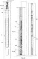
- Figure 2 is a view illustrating the running tool 200 in a run-in position.
- the running tool 200 includes the expander 250 that is disposed below the tubular 60.
- the running tool 200 also includes the engagement device 205 which is shown as drag blocks. The sequence of releasing the drag blocks is illustrated in Figures 5A-5C .
- the running tool 200 also includes a first jack 240 and a second jack 280 that move the expander 250 relative to the engagement device 205 in order to activate the anchor portion 50 of the expandable tubular assembly 75.
- the first and second jacks 240, 280 are configured to move the expander 250 through the expandable tubular assembly 75 while the engagement device 205 supports the expandable tubular assembly 75 in the borehole 10.
- the jacks 240, 280 work together to ensure that sufficient force is generated to move the expander 250 through the expandable tubular assembly 75.
- the jacks 240, 280 are configured to move (i.e., stroke) from a retracted position to an extended position.
- the running tool 200 in Figure 2 shows two jacks, any number of jacks may be attached to the expander 250 without departing from principles of the present invention.
- FIG 3 is a view illustrating the running tool 200 when the first jack 240 and the second jack 280 are activated.
- a blocking member 215 such as a ball or a dart
- a seat 220 which blocks the flow of fluid through the running tool 200 (see Figure 5D for an enlarged view of the blocking member 215 and the seat 220).
- fluid is pumped into the running tool 200 to increase the pressure in the bore 230 of the running tool 200.
- collet retainer 235 moves to open a port 210 between a first cup 245 and a second cup 255 of the jack 240.
- Figure 3A illustrates an enlarged view of the port 210 and collet retainer 235 in the first jack 240.
- Figure 3B illustrates an enlarged view of a port 270 and a cup 265 of the second jack 280.
- the port 270 is opened adjacent the cup 265 of the second jack 280.
- the port 270 is used as a fluid pathway between the bore 230 and a chamber 295 of the second jack 280.
- the chamber 295 is defined between the cup 265 and seals 305 disposed on an annular member 310.
- Figure 4 is a view illustrating the running tool 200 expanding the expandable tubular assembly 75.
- the movement of the expander 250 relative to the engagement device 205 is caused by jacks 240, 280.
- the flow of fluid through the bore 230 is restricted by blocking member 215 on the seat 220.
- a portion of the fluid pumped into the bore 230 enters a chamber 285 of the first jack 240 via the port 210.
- the chamber 285 is defined between the cups 245, 255 of the first jack 240.
- the cup 255 is operatively attached to the expander 250 by a mandrel 290 and the cup 245 is operatively attached to the engagement device 205.
- the cup 255 moves relative to the cup 245, which causes the expander 250 (and the mandrel 290) to move relative to the engagement device 205.
- a portion of the fluid in the bore 230 also enters the chamber 295 of the second jack 280 via the port 270.
- the chamber 295 of the second jack 280 is defined between the cup 265 and seals 305 on the annular member 310 ( Figure 3A ).
- the cup 265 is operatively attached to the expander 250 and the annular member 310 is operatively attached to the support shoulder 225 that is engaged with the upper portion of the tubular 60 of the expandable tubular assembly 75.
- the cup 265 moves relative to the annular member 310, which causes the expander 250 to move relative to the engagement device 205.
- the engagement device 205 is configured to support the expandable tubular assembly 75 while the anchor portion 50 is being activated by the expander 250.
- a releasing sleeve 315 that is configured to release the engagement device 205 in the running tool 200.
- the releasing sleeve 315 moves with the expander 250 through the expandable tubular assembly 75.
- the releasing sleeve 315 includes a shoulder 320 that is configured to engage a shoulder 330 of a locking mandrel 325 in the engagement device 205.
- Figure 5 is a view illustrating the release of the engagement device 205 in the running tool 200.
- the expander 250 moves through the expandable tubular assembly 75 until the anchor portion 50 of the expandable tubular assembly 75 is expanded radially outward into engagement with the borehole 10. At this point, the anchor portion 50 can support the expandable tubular assembly 75 in the borehole 10, and the engagement device 205 may be released from engagement with the expandable tubular assembly 75.
- the releasing process of the engagement device 205 is shown in Figures 5A-5C .
- the releasing process begins when the shoulder 320 of the releasing sleeve 315 contacts the shoulder 330 of the locking mandrel 325 as shown in Figure 5A .
- the releasing sleeve 315 moves with the expander 250.
- the releasing sleeve 315 is positioned within the running tool 200 such that the releasing sleeve 315 engages the locking mandrel 325 at a point after the expander 250 has expanded the anchor portion 50 and the jacks 240, 280 are near the end of their stroke.
- the releasing sleeve 315 automatically releases the engagement device 205 at a point after the expander 250 has expanded the anchor portion 50
- the releasing sleeve 315 applies a force on the locking mandrel 325 as the expander 250 continues to move through the expandable tubular assembly 75.
- a releasable connection 345 such as a shear pin, releases a connection between the locking mandrel 325 and a body portion 355 of the running tool 200.
- the locking mandrel 325 moves from under drag blocks 365 and into space 360 as shown in Figure 5B .
- the movement of the locking mandrel 325 allows the drag blocks 365 to collapse radially inward, which disengages the drag blocks 365 from grooves 370 in the tubular 60 of the expandable tubular assembly 75 as shown in Figure 5C .
- the engagement device 205 is released from engagement with the expandable tubular assembly 75.
- the releasing sleeve 315 also includes a ring member 380 that is configured to engage a groove 385 in a body portion of the running tool 200 as shown in Figure 5B .
- the engagement of the ring member 380 and the groove 385 locks the locking mandrel 325 to the body portion so that the locking mandrel 325 can no longer move under the drag blocks 365 to extend the drag blocks 365.
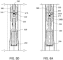
- Figure 6 is a view illustrating the opening of a by-pass port 340 in the running tool 200. As shown in Figure 6 , the jacks 240, 280 are extended and the blocking member 215 continues to block the flow of fluid through the bore 230.
- Figure 5D is an enlarged view of the by-pass port 340 in a closed position and Figure 6A is an enlarged view of the by-pass port 340 in an opened position.
- the blocking member 215 is in the seat 220.
- the seat 220 is an annular member that is connected to a mandrel 390 by a releasable connection 335. As shown, the seat 220 blocks the by-pass port 340 that is formed in the mandrel 390. As such, no fluid can enter into the by-pass port 340.
- fluid is introduced into the bore 230 and fluid pressure increases in the bore 230.
- the releasable connection 335 between the seat 220 and the mandrel 390 is released, which allows the seat 220 (and blocking member 215) to move relative to the mandrel 390 to expose the by-pass port 340 as shown in Figure 6A .
- a fluid pathway is thus created to allow fluid to move from the bore 230 into the by-pass port 340 and out through a port 350 to a location below the running tool 200.
- fluid pumped into the running tool 200 may by-pass the blocking member 215 and exit the bottom of the tool 200.
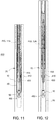
- Figure 7 is a view illustrating the running tool 200 expanding the expandable tubular assembly 75.
- the running tool 200 continues to expand the expandable tubular assembly 75 after the jacks 240, 280 have completed their strokes by mechanically pulling the running tool 200.
- the jack 280 is moved (i.e., restroked) from the extended position to the retracted position. In other words, the jack 280 moves back to the initial run-in position as shown in Figure 2 .
- the running tool 200 expands the rest of the expandable tubular assembly 75 by mechanically pulling the running tool 200. After the expandable tubular assembly 75 has been expanded, the running tool 200 is removed from the borehole 10.
- Figure 8 is a view illustrating the expander tool 400 of the expansion system 100 being lowered into the expandable tubular assembly 75.
- the expander tool 400 is positioned within the expandable tubular assembly 75 in order to expand the tubular 60 from the first diameter to the second larger diameter.
- the expander tool 400 is located within the expandable tubular assembly 75 such that the ramped portion 410 and the second expander 405 are disposed below the end of the expandable tubular assembly 75.
- Figure 9 is a view illustrating the second expander 405 of the expander tool 400 in a retracted position.
- Figure 10 is a view illustrating the second expander 405 of the expander tool 400 in an expanded position.
- the second expander 405 may include a plurality of individual segments that are configured to spread apart as the second expander 405 moves relative to the ramped portion 410.
- Each segment of the second expander 405 may include an extension member that is configured to interact with a respective groove in the ramped portion 410 as the second expander 405 moves between the retracted position and the expanded position.
- a blocking member 415 such as a ball or a dart
- a ball or a dart is dropped into a bore 430 in the expander tool 400 and lands on a seat 420, which blocks the flow of fluid through the expander tool 400.
- fluid pumped into the bore 430 of the expander tool 400 is directed through port 455 into a chamber 460 as shown in Figure 9A .
- a mandrel 470 applies a force on a releasable connection 465 between the mandrel 470 and a body member 480.
- the releasable connection 465 releases the connection between the mandrel 470 and the body member 480, which allows the mandrel 470 to move relative to the body member 480 as shown in Figure 10A .
- the mandrel 470 is connected to the second expander 405.
- the movement of the mandrel 470 causes the second expander 405 to move from the retracted position to the expanded position as the second expander 405 is urged up the ramped portion 410.
- the second expander 405 is locked in the expanded position by aligning and engaging a ring member 495 attached to the body member 480 with a groove 485 formed on the mandrel 470 as shown in Figures 9A and 10A .
- Figure 11 is a view illustrating the expander tool 400 expanding the expandable tubular assembly 75. After the second expander 405 is locked in the expanded position, the pressure in the expander tool 400 is released. Thereafter, the expander tool 400 is mechanically pulled through the expandable tubular assembly 75 to expand the expandable tubular assembly 75 to the second diameter.
- Figure 12 is a view illustrating the expander tool 400 after expansion of the expandable tubular assembly 75.
- the expander tool 400 is urged through the length of the expandable tubular assembly 75 and then positioned within the borehole 10 as shown.
- the second expander 405 is unlocked and moves from the expanded position to the retracted position by hydraulic activation.
- Figures 11 and 11A illustrate the second expander 405 in the expanded position
- Figures 12 and 12A illustrate the second expander 405 in the retracted position. The unlocking of the second expander 405 will be described in relation to Figures 11A and 12A .
- the bore 430 of the expander tool 400 is in fluid communication with a port 425.
- fluid is pumped down the bore 430 and enters chamber 565 via the port 425.
- a mandrel 440 applies a force on a releasable connection 435, such as a shear ring, between the mandrel 440 and a body member 570.
- the releasable connection 435 releases the connection between the mandrel 440 and the body member 565, which allows the mandrel 440 to move relative to the body member 570 as shown in Figure 12A .
- the mandrel 440 is connected to the ramped portion 410.
- the movement of the mandrel 440 causes the ramped portion 410 to move from under the second expander 405, which causes the second expander 405 to move from the expanded position to the retracted position as shown in Figure 12 .
- a port 475 in the mandrel 440 aligns with a port 445 in the body member 570 (compare Figures 11A and 12A ), which allows fluid communication within the expander tool 400. Thereafter, the expander tool 400 may be removed from the borehole 10.
- Figure 13 is a view illustrating the second expander 405 of the expander tool 400 mechanically moved from the expanded position to the retracted position. If the second expander 405 is unable to be hydraulically unlocked as set forth in Figures 11A and 12A , the second expander 405 may be mechanically unlocked. To unlock the second expander 405 mechanically, the expander tool 400 is pulled up until the expander tool 400 contacts a casing 575 (i.e., another expanded tubular assembly or a parent casing). As the expander tool 400 is pulled relative to the casing 575, a force is applied to a releasable connection 545, such as a shear ring, between the ramp portion 410 and a body member 580.
- a releasable connection 545 such as a shear ring
- the releasable connection 545 releases the connection between the ramp portion 410 and the body member 580 which allows the ramp portion 410 to move relative to the body member 580 as shown in Figure 13A .
- the ramped portion 410 moves from under the second expander 405 which causes the second expander 405 to move from the expanded position to the retracted position. Thereafter, the expander tool 400 may be removed from the borehole 10.
- Figures 14A-14D are views illustrating a slip arrangement 150.
- the slip arrangement 150 is used as the engagement device 205 between the tool 200 and the expandable tubular assembly 75.
- the slip arrangement 150 is a different embodiment of the engagement device 205 shown in Figures 5A-5C which is illustrated as a drag block arrangement.
- the slip arrangement 150 includes a set of slips 160 that move between an extended position and a retracted position.
- the slips 160 are in the extended position and engaged with the tubular of the expandable tubular assembly.
- a releasing mechanism 115 is mechanically pulled in the direction of the slips 160.
- the releasing mechanism 115 causes a shear pin 120 to release a holding sleeve 165.
- a spring loaded releasing sleeve 125 moves back.
- the shear pin 120 has been sheared, and further mechanical pull on the releasing member 115 causes the holding sleeve 165 to move an upper slip retainer 130 toward a shoulder 180.
- the upper slip retainer 130 moves relative to the slips 160, which causes the slips 160 to move radially inward.
- the upper slip retainer 130 has contacted the shoulder 180, and the spring loaded releasing sleeve 125 has extended, which causes the slips 160 to move to the retracted position. Thereafter, the tool 200 may be moved through the expandable tubular assembly similar to Figure 1C .
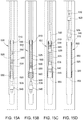
- Figures 15A-15D are views illustrating a running tool 535.
- the tool 535 is used to lower and expand an expandable tubular assembly 500 in a single trip.
- the running tool 535 includes similar components as the expansion system 100 described in Figures 1-13 .
- Figure 15A illustrates the placement of the expandable tubular assembly 500 adjacent an under-reamed portion of the borehole 560.
- the expandable tubular assembly 500 is connected to the tool 535 by a releasable engagement device 530, such as a latch, collet, slips, thread, shear member or any other suitable mechanism.
- the expandable tubular assembly 500 includes an anchor portion 550 and a seal portion 510 disposed around a tubular 525.
- the anchor portion 550 is positioned between the engagement device 530 (i.e., fixed point) and an end 555 (i.e., free point) of the tubular 525.
- Figure 15B illustrates a first expander 520 expanding the tubular 525 adjacent the anchor portion 550.
- the first expander 520 is configured to move relative to the engagement device 530 by a hydraulic or mechanical moving device, such as jack 580.
- a hydraulic or mechanical moving device such as jack 580.
- the first expander 520 expands the tubular 525, the length between the end 525 of the tubular 525 and the engagement device 530 changes from a first length to a second shorter length, which causes the anchor portion 550 to activate.
- the tubular 525 becomes axially shorter as the tubular 525 is expanded radially.
- the reduction in the length of the tubular 525 occurs between the fixed end (engagement device 530) and the free end 505.
- Figure 15C illustrates an optional second expander 540 further expanding the expandable tubular assembly 500.
- the engagement device 530 is released and the running tool 535 is mechanically pulled upward to expand (or further expand) the tubular 525 of the expandable tubular assembly 500 by using the first expander 520 and the second expander 540.
- the jack 580 may be used to move both the first expander 520 and the second expander 540 through the expandable tubular assembly 500 in addition to the mechanical over pull or in place of the mechanical over pull.
- Figure 15D illustrates the removal of the running tool 535 after expansion of the expandable tubular assembly 500.
Abstract
Description
- The present invention relates to wellbore completion. More particularly, the invention relates to an apparatus and method for expanding an expandable tubular assembly in a borehole.
- Expandable technology enables a smaller-diameter tubular to pass through a larger-diameter tubular, and thereafter be expanded to a larger diameter. In this respect, expandable technology permits the formation of a tubular string having a substantially constant inner diameter. When an expandable tubular is run into a borehole, it must be anchored within the borehole at the desired depth to prevent movement of the expandable tubular during the expansion process. Anchoring the expandable tubular within the borehole allows expansion of the length of the expandable tubular in the borehole.
- The expandable tubular that is used to isolate the area of interest is often run into the borehole after previous strings of casing (e.g., parent casing) are already set within the borehole. The expandable tubular for isolating the area of interest must be run through the inner diameter of the parent casing to reach the portion of the open-hole borehole slated for isolation, which is located below the previously set parent casing. Accordingly, the outer diameter of the anchor and the expandable tubular must be smaller than the parent casing in the borehole in order to run through the parent casing to the depth at which the open-hole borehole exists. After locating the expandable tubular below the parent casing, a conventional expander tool is pushed or pulled through the expandable tubular to expand the anchor and the expandable tubular into contact with the surrounding borehole.
- Oftentimes, it is desired to have the inner diameter of the expandable tubular to be at least as large as the inner diameter of the parent casing so that drilling can continue with the same drill bit. To achieve an inner diameter of the expandable tubular to be at least as large as the inner diameter of the parent casing, the expandable tubular may require a 28% expansion ratio. However, the conventional expander tool can typically obtain a 20% expansion ratio. Therefore, there is a need for an expansion system for expanding the expandable tubular to the required expansion ratio.
- The present invention generally relates to an apparatus and method for expanding an expandable tubular assembly in a borehole. In one embodiment, a system for expanding a tubular having an anchor portion in a borehole is provided. The system includes a running tool configured to position the tubular in the borehole. The running tool including a first expander configured to activate the anchor portion by expanding the tubular to a first diameter. The system further includes a second expander configured to expand the tubular to a second larger diameter, wherein the second expander is movable between a retracted position and an expanded position.
- In another embodiment, a method of expanding a tubular having an anchor portion in a borehole is provided. The method includes the step of positioning the tubular in the borehole using a running tool that includes a first expander and an engagement device for retaining the tubular. The method further includes the step of activating the anchor portion by expanding a portion of the tubular to a first diameter using the first expander while the engagement device supports the tubular. The method also includes the step of releasing the engagement device from the tubular and expanding the remaining portion of the tubular to the first diameter using the first expander. Furthermore, the method includes the step of positioning a second expander in the tubular. Additionally, the method includes the step of expanding the tubular to a second larger diameter by using the second expander.
- In one aspect, a tool for expanding an open-hole anchor in a borehole is provided. The tool includes an engagement device configured to selectively engage the open-hole anchor. The tool further includes an expander configured to expand the open-hole anchor. Additionally, the tool includes one or more jacks configured to move the expander relative to the engagement device in order to expand an anchor portion of the open-hole anchor.
- In an additional aspect, a system for use in a wellbore is provided. The system includes a tubular having an anchor portion. The system further includes a running tool configured to position the tubular in the wellbore, the running tool including a first expander configured to activate the anchor portion by expanding the tubular to a first diameter. The system also includes a second expander configured to expand the tubular to a second larger diameter, wherein the second expander is movable between a retracted position and an expanded position.
- So that the manner in which the above recited features of the present invention can be understood in detail, a more particular description of the invention, briefly summarized above, may be had by reference to embodiments, some of which are illustrated in the appended drawings. It is to be noted, however, that the appended drawings illustrate only typical embodiments of this invention and are therefore not to be considered limiting of its scope, for the invention may admit to other equally effective embodiments.
-
Figures 1A-1H are views illustrating the steps of expanding an expandable tubular assembly in a borehole using an expansion system. -
Figure 2 is a view illustrating a running tool of the expansion system. -
Figure 3 is a view illustrating the activation of a first jack and a second jack in the running tool. -
Figure 3A is an enlarged view illustrating the first jack. -
Figure 3B is an enlarged view illustrating the second jack. -
Figure 4 is a view illustrating the expansion of the expandable tubular assembly. -
Figure 5 is a view illustrating the release of an engagement device in the running tool. -
Figures 5A-5C are views illustrating the releasing process of the engagement device. -
Figure 5D is an enlarged view of a by-pass port in a closed position. -
Figure 6 is a view illustrating the opening of the by-pass port in the running tool. -
Figure 6A is an enlarged view of the by-pass port in an opened position. -
Figure 7 is a view illustrating the running tool in the expandable tubular assembly during the expansion operation. -
Figure 8 is a view illustrating an expander tool of the expansion system being lowered into the expandable tubular assembly. -
Figure 9 is a view illustrating an expander of the expander tool in a retracted position. -
Figure 9A is an enlarged view illustrating the expander of the expander tool in the retracted position. -
Figure 10 is a view illustrating the expander of the expander tool in an expanded position. -
Figure 10A is an enlarged view illustrating the expander of the expander tool in the expanded position. -
Figure 11 is a view illustrating the expander tool expanding the expandable tubular assembly. -
Figure 11A is an enlarged view illustrating a hydraulic release mechanism of the expander. -
Figure 12 is a view illustrating the expander tool removed from the expandable tubular assembly. -
Figure 12A is an enlarged view illustrating the activation of the hydraulic release mechanism of the expander. -
Figure 13 is a view illustrating the expander tool positioned adjacent a casing string. -
Figure 13A is an enlarged view illustrating the activation of a mechanical release mechanism of the expander. -
Figures 14A-14D are views illustrating the releasing process of a slip arrangement. -
Figures 15A-15D are views illustrating the steps of expanding an expandable tubular assembly in a borehole using a running tool. - The present invention generally relates to an expansion system for use with a tubular with an anchor. The expansion system will be described herein in relation to expanding the tubular into an open hole. It is to be understood, however, that the expansion system may also be used to expand the tubular inside of a cased borehole without departing from principles of the present invention. To better understand the novelty of the expansion system of the present invention and the methods of use thereof, reference is hereafter made to the accompanying drawings.
-
Figures 1A-1H generally illustrate the steps of an expansion operation that uses anexpansion system 100 of the present invention. The details of theexpansion system 100 will be described inFigures 2-13 . The expansion of an expandabletubular assembly 75 is done in a first step and a second step to obtain a 28% expansion ratio. The first step is shown inFigures 1A-1D in which arunning tool 200 of theexpansion system 100 is used to expand the expandabletubular assembly 75 to a first diameter. The second step is shown inFigures 1E-1G in which anexpander tool 400 of theexpansion system 100 is used to expand the expandabletubular assembly 75 to a second larger diameter. - As shown in
Figure 1A , the expandabletubular assembly 75 is lowered into a borehole 10 attached to the runningtool 200. The expandabletubular assembly 75 is positioned adjacent an under-reamed portion of theborehole 10. The expandabletubular assembly 75 is connected to the runningtool 200 by areleasable engagement device 205, such as a latch, drag blocks, collet, slips, thread, shear member or any other suitable mechanism. The expandabletubular assembly 75 includes ananchor portion 50 and seals 55 disposed around a tubular 60. Theseals 55 may be at any location on the tubular 60, such as both ends of the tubular 60. Thereleasable engagement device 205 is configured to support the expandabletubular assembly 75 while theanchor portion 50 is being activated. After activation, theanchor portion 50 is configured to support the expandabletubular assembly 75 in theborehole 10. Thereafter, thereleasable engagement device 205 is released from the expandabletubular assembly 75. In one embodiment, thereleasable engagement device 205 is automatically released from the expandabletubular assembly 75 once anexpander 250 of the runningtool 200 passes through theanchor portion 50. Theanchor portion 50 is positioned between the engagement device 205 (i.e., fixed point) and an end 65 (i.e., free point) of the tubular 60. In one embodiment, theanchor portion 50 may comprise a plurality of bands, wherein each band has an end connected to the tubular 60. The bands will bow radially outward as the tubular 60 becomes axially shorter as the tubular 60 is expanded radially. In another embodiment, theanchor portion 50 is a slip arrangement. -
Figure 1B illustrates theexpander 250 of the runningtool 200 expanding the tubular 60 adjacent theanchor portion 50. Theexpander 250 is configured to move relative to theengagement device 205 byjacks 275 in order activate theanchor portion 50. The details of thejacks 275 will be explained in more detail inFigures 3 and4 . As theexpander 250 expands the tubular 60, the length between theend 65 of the tubular 60 and theengagement device 205 changes from a first length to a second shorter length, which causes theanchor portion 50 to activate. In other words, the tubular 60 becomes axially shorter as the tubular 60 is expanded radially. The reduction in the length of the tubular 60 occurs between the fixed end (engagement device 205) and thefree end 65. -
Figure 1C illustrates theexpander 250 of the runningtool 200 further expanding the tubular 60. Theanchor portion 50 is configured to support the tubular 60 in theborehole 10 after theanchor portion 50 is activated, and thus theengagement device 205 may be released from the tubular 60. Thereafter, theexpander 250 may be urged through the tubular 60 by mechanically pulling on the runningtool 200, such as pulling thetool 200 from the surface of theborehole 10.Figure 1D illustrates the removal of the runningtool 200 after expansion of the expandabletubular assembly 75 to the first diameter. The expandabletubular assembly 75 may include an optional centralizer proximate an upper end of the tubular 60 to centralize the tubular 60 in theborehole 10. In one embodiment, the centralizer may comprise a plurality of fingers separated by slots formed at the upper end of the tubular 60. The fingers are configured to bend radially outward and engage thewellbore 10 as theexpander 250 expands the tubular 60. In another embodiment, the centralizer may comprise a plurality of bands, wherein each band has an end connected to the tubular 60. The bands will bow radially outward as the tubular 60 is expanded radially outward by theexpander 250. The centralizer may be useful in the positioning the tubular 60 in the borehole 10 to allow theexpander tool 400 to be placed within the expandabletubular assembly 75 after therunning tool 200 has been removed. - As shown in
Figure 1E , theexpander tool 400 of theexpansion system 100 is lowered into the expandabletubular assembly 75. Theexpander tool 400 optionally includes adevice 490, such as a drill bit, a mill, brushes, a scraper, a filter member, a junk basket, or any other cleaning device, that may be used to remove (dislodge) debris or other material in the borehole 10 that may hinder the placement of theexpander tool 400 in the expandabletubular assembly 75. Thedevice 490 may also be used to drill or mill a portion of theborehole 10. Theexpander tool 400 includes a formablesecond expander 405 that is configured to move between a radially retracted position as shown inFigure 1E and a radially expanded position as shown inFigure 1F . As will be described herein, thesecond expander 405 moves from the retracted position and the expanded position through the use of acylinder member 450 which urges a rampedportion 410 under thesecond expander 405. Other types of formable expanders may be used without departing from principles of the present invention. An example of an expander is described inUS Patent No. 7,121,351 entitled "Apparatus and method for completing a wellbore" to Mike Luke, which is incorporated herein by reference. -
Figure 1F illustrates thesecond expander 405 of theexpander tool 400 in the expanded position. After thesecond expander 405 is moved to the expanded position, theexpander tool 400 travels through the expandabletubular assembly 75 by mechanically pulling on theexpander tool 400. As thesecond expander 405 moves through the tubular 60 adjacent theanchor portion 50, the tubular 60 is expanded to the second larger diameter which causes theanchor portion 50 to further engage the borehole 10 as shown inFigure 1G . -
Figure 1H illustrates theexpander tool 400 of theexpansion system 100 being removed from the borehole 10 after expansion of the expandabletubular assembly 75. After the expandabletubular assembly 75 is expanded to the second larger diameter, thesecond expander 405 is moved from the expanded position to the retracted position by moving the rampedportion 410 away from thesecond expander 405. Thereafter, theexpander tool 400 is removed from theborehole 10. In another embodiment, the expansion of the expandabletubular assembly 75 may be done in a single step to obtain a 28% expansion ratio by using therunning tool 200 of theexpansion system 100. In a further embodiment, the expandabletubular assembly 75 may be expanded in a non-enlarged portion of theborehole 10. -
Figure 2 is a view illustrating the runningtool 200 in a run-in position. As shown inFigure 2 , the runningtool 200 includes theexpander 250 that is disposed below the tubular 60. The runningtool 200 also includes theengagement device 205 which is shown as drag blocks. The sequence of releasing the drag blocks is illustrated inFigures 5A-5C . - The running
tool 200 also includes afirst jack 240 and asecond jack 280 that move theexpander 250 relative to theengagement device 205 in order to activate theanchor portion 50 of the expandabletubular assembly 75. The first andsecond jacks expander 250 through the expandabletubular assembly 75 while theengagement device 205 supports the expandabletubular assembly 75 in theborehole 10. Thejacks expander 250 through the expandabletubular assembly 75. Thejacks first jack 240 moves from the retracted position to the extended position, a portion of thejack 240 is supported by theengagement device 205. As thesecond jack 280 moves from the retracted position to the extended position, a portion of thejack 280 is supported by asupport shoulder 225 that engages an upper portion of the tubular 60 of the expandabletubular assembly 75. Although the runningtool 200 inFigure 2 shows two jacks, any number of jacks may be attached to theexpander 250 without departing from principles of the present invention. -
Figure 3 is a view illustrating the runningtool 200 when thefirst jack 240 and thesecond jack 280 are activated. To activate thejacks member 215, such as a ball or a dart, is dropped into abore 230 in the runningtool 200 and lands on aseat 220 which blocks the flow of fluid through the running tool 200 (seeFigure 5D for an enlarged view of the blockingmember 215 and the seat 220). Thereafter, fluid is pumped into the runningtool 200 to increase the pressure in thebore 230 of the runningtool 200. At a predetermined pressure,collet retainer 235 moves to open aport 210 between afirst cup 245 and asecond cup 255 of thejack 240.Figure 3A illustrates an enlarged view of theport 210 andcollet retainer 235 in thefirst jack 240.Figure 3B illustrates an enlarged view of aport 270 and acup 265 of thesecond jack 280. In a similar manner, theport 270 is opened adjacent thecup 265 of thesecond jack 280. Theport 270 is used as a fluid pathway between thebore 230 and achamber 295 of thesecond jack 280. As shown inFigure 3B , thechamber 295 is defined between thecup 265 andseals 305 disposed on anannular member 310. -
Figure 4 is a view illustrating the runningtool 200 expanding the expandabletubular assembly 75. The movement of theexpander 250 relative to theengagement device 205 is caused byjacks Figure 4 , the flow of fluid through thebore 230 is restricted by blockingmember 215 on theseat 220. As a result, a portion of the fluid pumped into thebore 230 enters achamber 285 of thefirst jack 240 via theport 210. Thechamber 285 is defined between thecups first jack 240. Thecup 255 is operatively attached to theexpander 250 by amandrel 290 and thecup 245 is operatively attached to theengagement device 205. As thechamber 285 of thefirst jack 240 fills with fluid, thecup 255 moves relative to thecup 245, which causes the expander 250 (and the mandrel 290) to move relative to theengagement device 205. A portion of the fluid in thebore 230 also enters thechamber 295 of thesecond jack 280 via theport 270. Thechamber 295 of thesecond jack 280 is defined between thecup 265 and seals 305 on the annular member 310 (Figure 3A ). Thecup 265 is operatively attached to theexpander 250 and theannular member 310 is operatively attached to thesupport shoulder 225 that is engaged with the upper portion of the tubular 60 of the expandabletubular assembly 75. As thechamber 295 of thesecond jack 280 fills with fluid, thecup 265 moves relative to theannular member 310, which causes theexpander 250 to move relative to theengagement device 205. As set forth herein, theengagement device 205 is configured to support the expandabletubular assembly 75 while theanchor portion 50 is being activated by theexpander 250. Also shown inFigure 4 is a releasingsleeve 315 that is configured to release theengagement device 205 in the runningtool 200. The releasingsleeve 315 moves with theexpander 250 through the expandabletubular assembly 75. The releasingsleeve 315 includes ashoulder 320 that is configured to engage ashoulder 330 of a lockingmandrel 325 in theengagement device 205. -
Figure 5 is a view illustrating the release of theengagement device 205 in the runningtool 200. Theexpander 250 moves through the expandabletubular assembly 75 until theanchor portion 50 of the expandabletubular assembly 75 is expanded radially outward into engagement with theborehole 10. At this point, theanchor portion 50 can support the expandabletubular assembly 75 in theborehole 10, and theengagement device 205 may be released from engagement with the expandabletubular assembly 75. - The releasing process of the
engagement device 205 is shown inFigures 5A-5C . The releasing process begins when theshoulder 320 of the releasingsleeve 315 contacts theshoulder 330 of the lockingmandrel 325 as shown inFigure 5A . As set forth herein, the releasingsleeve 315 moves with theexpander 250. The releasingsleeve 315 is positioned within the runningtool 200 such that the releasingsleeve 315 engages the lockingmandrel 325 at a point after theexpander 250 has expanded theanchor portion 50 and thejacks sleeve 315 automatically releases theengagement device 205 at a point after theexpander 250 has expanded theanchor portion 50 - The releasing
sleeve 315 applies a force on the lockingmandrel 325 as theexpander 250 continues to move through the expandabletubular assembly 75. At a predetermined force, areleasable connection 345, such as a shear pin, releases a connection between the lockingmandrel 325 and abody portion 355 of the runningtool 200. After theconnection 345 has been released, the lockingmandrel 325 moves from under drag blocks 365 and intospace 360 as shown inFigure 5B . The movement of the lockingmandrel 325 allows the drag blocks 365 to collapse radially inward, which disengages the drag blocks 365 fromgrooves 370 in the tubular 60 of the expandabletubular assembly 75 as shown inFigure 5C . At this point, theengagement device 205 is released from engagement with the expandabletubular assembly 75. The releasingsleeve 315 also includes aring member 380 that is configured to engage agroove 385 in a body portion of the runningtool 200 as shown inFigure 5B . The engagement of thering member 380 and thegroove 385 locks the lockingmandrel 325 to the body portion so that the lockingmandrel 325 can no longer move under the drag blocks 365 to extend the drag blocks 365. -
Figure 6 is a view illustrating the opening of a by-pass port 340 in the runningtool 200. As shown inFigure 6 , thejacks member 215 continues to block the flow of fluid through thebore 230. -
Figure 5D is an enlarged view of the by-pass port 340 in a closed position andFigure 6A is an enlarged view of the by-pass port 340 in an opened position. As shown inFigure 5D , the blockingmember 215 is in theseat 220. Theseat 220 is an annular member that is connected to amandrel 390 by areleasable connection 335. As shown, theseat 220 blocks the by-pass port 340 that is formed in themandrel 390. As such, no fluid can enter into the by-pass port 340. To open the by-pass port 340, fluid is introduced into thebore 230 and fluid pressure increases in thebore 230. At a predetermined pressure, such as 5000 psi, thereleasable connection 335 between theseat 220 and themandrel 390 is released, which allows the seat 220 (and blocking member 215) to move relative to themandrel 390 to expose the by-pass port 340 as shown inFigure 6A . A fluid pathway is thus created to allow fluid to move from thebore 230 into the by-pass port 340 and out through aport 350 to a location below the runningtool 200. As a result, fluid pumped into the runningtool 200 may by-pass the blockingmember 215 and exit the bottom of thetool 200. -
Figure 7 is a view illustrating the runningtool 200 expanding the expandabletubular assembly 75. The runningtool 200 continues to expand the expandabletubular assembly 75 after thejacks tool 200. As the runningtool 200 is pulled, thejack 280 is moved (i.e., restroked) from the extended position to the retracted position. In other words, thejack 280 moves back to the initial run-in position as shown inFigure 2 . The runningtool 200 expands the rest of the expandabletubular assembly 75 by mechanically pulling the runningtool 200. After the expandabletubular assembly 75 has been expanded, the runningtool 200 is removed from theborehole 10. -
Figure 8 is a view illustrating theexpander tool 400 of theexpansion system 100 being lowered into the expandabletubular assembly 75. After therunning tool 200 has been removed from theborehole 10, theexpander tool 400 is positioned within the expandabletubular assembly 75 in order to expand the tubular 60 from the first diameter to the second larger diameter. As shown, theexpander tool 400 is located within the expandabletubular assembly 75 such that the rampedportion 410 and thesecond expander 405 are disposed below the end of the expandabletubular assembly 75. -
Figure 9 is a view illustrating thesecond expander 405 of theexpander tool 400 in a retracted position.Figure 10 is a view illustrating thesecond expander 405 of theexpander tool 400 in an expanded position. Thesecond expander 405 may include a plurality of individual segments that are configured to spread apart as thesecond expander 405 moves relative to the rampedportion 410. Each segment of thesecond expander 405 may include an extension member that is configured to interact with a respective groove in the rampedportion 410 as thesecond expander 405 moves between the retracted position and the expanded position. - After the
expander tool 400 is positioned within the expandabletubular assembly 75, a blockingmember 415, such as a ball or a dart, is dropped into abore 430 in theexpander tool 400 and lands on aseat 420, which blocks the flow of fluid through theexpander tool 400. Thereafter, fluid pumped into thebore 430 of theexpander tool 400 is directed throughport 455 into achamber 460 as shown inFigure 9A . As thechamber 460 enlarges due to the fluid, amandrel 470 applies a force on areleasable connection 465 between themandrel 470 and abody member 480. At a predetermined force, thereleasable connection 465 releases the connection between themandrel 470 and thebody member 480, which allows themandrel 470 to move relative to thebody member 480 as shown inFigure 10A . Themandrel 470 is connected to thesecond expander 405. Thus, the movement of themandrel 470 causes thesecond expander 405 to move from the retracted position to the expanded position as thesecond expander 405 is urged up the rampedportion 410. Thesecond expander 405 is locked in the expanded position by aligning and engaging aring member 495 attached to thebody member 480 with agroove 485 formed on themandrel 470 as shown inFigures 9A and 10A . -
Figure 11 is a view illustrating theexpander tool 400 expanding the expandabletubular assembly 75. After thesecond expander 405 is locked in the expanded position, the pressure in theexpander tool 400 is released. Thereafter, theexpander tool 400 is mechanically pulled through the expandabletubular assembly 75 to expand the expandabletubular assembly 75 to the second diameter. -
Figure 12 is a view illustrating theexpander tool 400 after expansion of the expandabletubular assembly 75. Theexpander tool 400 is urged through the length of the expandabletubular assembly 75 and then positioned within theborehole 10 as shown. At this point, thesecond expander 405 is unlocked and moves from the expanded position to the retracted position by hydraulic activation.Figures 11 and11A illustrate thesecond expander 405 in the expanded position andFigures 12 and12A illustrate thesecond expander 405 in the retracted position. The unlocking of thesecond expander 405 will be described in relation toFigures 11A and 12A . - As shown in
Figure 11A , thebore 430 of theexpander tool 400 is in fluid communication with aport 425. To unlock thesecond expander 405, fluid is pumped down thebore 430 and enterschamber 565 via theport 425. As thechamber 565 enlarges due to the fluid, amandrel 440 applies a force on areleasable connection 435, such as a shear ring, between themandrel 440 and abody member 570. At a predetermined force, thereleasable connection 435 releases the connection between themandrel 440 and thebody member 565, which allows themandrel 440 to move relative to thebody member 570 as shown inFigure 12A . Themandrel 440 is connected to the rampedportion 410. Thus, the movement of themandrel 440 causes the rampedportion 410 to move from under thesecond expander 405, which causes thesecond expander 405 to move from the expanded position to the retracted position as shown inFigure 12 . In addition, as themandrel 440 moves relative to thebody member 570, aport 475 in themandrel 440 aligns with aport 445 in the body member 570 (compareFigures 11A and 12A ), which allows fluid communication within theexpander tool 400. Thereafter, theexpander tool 400 may be removed from theborehole 10. -
Figure 13 is a view illustrating thesecond expander 405 of theexpander tool 400 mechanically moved from the expanded position to the retracted position. If thesecond expander 405 is unable to be hydraulically unlocked as set forth inFigures 11A and 12A , thesecond expander 405 may be mechanically unlocked. To unlock thesecond expander 405 mechanically, theexpander tool 400 is pulled up until theexpander tool 400 contacts a casing 575 (i.e., another expanded tubular assembly or a parent casing). As theexpander tool 400 is pulled relative to thecasing 575, a force is applied to a releasable connection 545, such as a shear ring, between theramp portion 410 and abody member 580. At a predetermined force, the releasable connection 545 releases the connection between theramp portion 410 and thebody member 580 which allows theramp portion 410 to move relative to thebody member 580 as shown inFigure 13A . In turn, the rampedportion 410 moves from under thesecond expander 405 which causes thesecond expander 405 to move from the expanded position to the retracted position. Thereafter, theexpander tool 400 may be removed from theborehole 10. -
Figures 14A-14D are views illustrating aslip arrangement 150. Theslip arrangement 150 is used as theengagement device 205 between thetool 200 and the expandabletubular assembly 75. Theslip arrangement 150 is a different embodiment of theengagement device 205 shown inFigures 5A-5C which is illustrated as a drag block arrangement. Theslip arrangement 150 includes a set ofslips 160 that move between an extended position and a retracted position. InFigure 14A , theslips 160 are in the extended position and engaged with the tubular of the expandable tubular assembly. To move theslips 160 from the extended position to the retracted position, a releasingmechanism 115 is mechanically pulled in the direction of theslips 160. The releasingmechanism 115 causes ashear pin 120 to release a holdingsleeve 165. At this point, a spring loaded releasingsleeve 125 moves back. InFigure 14B , theshear pin 120 has been sheared, and further mechanical pull on the releasingmember 115 causes the holdingsleeve 165 to move anupper slip retainer 130 toward ashoulder 180. InFigure 14C , theupper slip retainer 130 moves relative to theslips 160, which causes theslips 160 to move radially inward. InFigure 14D , theupper slip retainer 130 has contacted theshoulder 180, and the spring loaded releasingsleeve 125 has extended, which causes theslips 160 to move to the retracted position. Thereafter, thetool 200 may be moved through the expandable tubular assembly similar toFigure 1C . -
Figures 15A-15D are views illustrating a runningtool 535. Thetool 535 is used to lower and expand an expandabletubular assembly 500 in a single trip. The runningtool 535 includes similar components as theexpansion system 100 described inFigures 1-13 . -
Figure 15A illustrates the placement of the expandabletubular assembly 500 adjacent an under-reamed portion of theborehole 560. The expandabletubular assembly 500 is connected to thetool 535 by areleasable engagement device 530, such as a latch, collet, slips, thread, shear member or any other suitable mechanism. The expandabletubular assembly 500 includes ananchor portion 550 and aseal portion 510 disposed around a tubular 525. Theanchor portion 550 is positioned between the engagement device 530 (i.e., fixed point) and an end 555 (i.e., free point) of the tubular 525. -
Figure 15B illustrates afirst expander 520 expanding the tubular 525 adjacent theanchor portion 550. Thefirst expander 520 is configured to move relative to theengagement device 530 by a hydraulic or mechanical moving device, such asjack 580. As thefirst expander 520 expands the tubular 525, the length between theend 525 of the tubular 525 and theengagement device 530 changes from a first length to a second shorter length, which causes theanchor portion 550 to activate. In other words, the tubular 525 becomes axially shorter as the tubular 525 is expanded radially. The reduction in the length of the tubular 525 occurs between the fixed end (engagement device 530) and the free end 505. -
Figure 15C illustrates an optionalsecond expander 540 further expanding the expandabletubular assembly 500. After the expandabletubular assembly 500 is attached to theborehole 560 by theanchor portion 550, theengagement device 530 is released and the runningtool 535 is mechanically pulled upward to expand (or further expand) thetubular 525 of the expandabletubular assembly 500 by using thefirst expander 520 and thesecond expander 540. In another embodiment, thejack 580 may be used to move both thefirst expander 520 and thesecond expander 540 through the expandabletubular assembly 500 in addition to the mechanical over pull or in place of the mechanical over pull.Figure 15D illustrates the removal of the runningtool 535 after expansion of the expandabletubular assembly 500. - While the foregoing is directed to embodiments of the present invention, other and further embodiments of the invention may be devised without departing from the basic scope thereof, and the scope thereof is determined by the appended claims.
- The invention may include one or more of the following embodiments:
- 1. A system for expanding a tubular having an anchor portion in a borehole, the system comprising:
- a running tool configured to position the tubular in the borehole, the running tool including a first expander configured to activate the anchor portion by expanding the tubular to a first diameter; and
- a second expander configured to expand the tubular to a second larger diameter, wherein the second expander is movable between a retracted position and an expanded position.
- 2. The system of
embodiment 1, wherein the running tool includes an engagement device that is configured to selectively engage the tubular. - 3. The system of embodiment 2, wherein the running tool includes one or more jacks to move the first expander relative to the engagement device.
- 4. The system of embodiment 2, wherein the first expander is configured to activate the anchor portion while the engagement device holds the tubular.
- 5. The system of embodiment 2, wherein the engagement device is configured to be automatically released from the tubular at a point after the anchor portion has been activated.
- 6. The system of
embodiment 1, wherein the second expander is attached to the running tool. - 7. The system of
embodiment 1, wherein the second expander moves between the retracted position and the expanded position as the second expander moves along a ramped portion. - 8. The system of
embodiment 1, wherein a drill bit is disposed below the second expander. - 9. A method of expanding a tubular having an anchor portion in a borehole, the method comprising:
- positioning the tubular in the borehole using a running tool that includes a first expander and an engagement device for retaining the tubular;
- activating the anchor portion by expanding a portion of the tubular to a first diameter using the first expander while the engagement device supports the tubular;
- releasing the engagement device from the tubular and expanding the remaining portion of the tubular to the first diameter using the first expander;
- positioning a second expander in the tubular; and
- expanding the tubular to a second larger diameter by using the second expander.
- 10. The method of embodiment 9, further comprising activating one or more jacks in the running tool to move the first expander relative to the engagement device.
- 11. The method of embodiment 9, further comprising automatically releasing the engagement device from the tubular after the anchor portion is activated.
- 12. The method of embodiment 9, wherein the second expander is movable between a retracted position and an expanded position.
- 13. The method of embodiment 12, wherein the second expander is positioned in the tubular such that the second expander is disposed outside of the tubular.
- 14. The method of embodiment 9, further comprising drilling a portion of the borehole with a drill bit attached to the second expander prior to expanding the tubular to the second larger diameter.
- 15. The method of embodiment 9, wherein the tubular is expanded to the first diameter and the second larger diameter in a single trip.
- 16. The method of embodiments 9, wherein the tubular is expanded to the first diameter and the second larger diameter in more than one trip.
- 17. A tool for expanding an open-hole anchor in a borehole, the tool comprising:
- an engagement device configured to selectively engage the open-hole anchor;
- an expander configured to expand the open-hole anchor; and
- one or more jacks configured to move the expander relative to the engagement device in order to expand an anchor portion of the open-hole anchor.
- 18. The tool of embodiment 17, wherein the one or more jacks move the expander through the anchor portion while the engagement device supports the tubular.
- 19. The tool of embodiment 17, wherein the engagement device is configured to disengage from the open-hole anchor after the anchor portion is expanded.
- 20. The tool of embodiment 17, wherein the engagement device includes drag blocks that engage grooves in the open-hole anchor.
- 21. The tool of embodiment 17, wherein the engagement device includes slips that engage a portion of the open-hole anchor.
- 22. The tool of embodiment 17, wherein the expander is mechanically pulled through the open-hole anchor after the anchor portion is expanded.
- 23. A system for use in a wellbore, the system comprising:
- a tubular having an anchor portion;
- a running tool configured to position the tubular in the wellbore, the running tool including a first expander configured to activate the anchor portion by expanding the tubular to a first diameter; and
- a second expander configured to expand the tubular to a second larger diameter, wherein the second expander is movable between a retracted position and an expanded position.
- 24. The system of embodiment 23, wherein the anchor portion is located proximate a bottom portion of the tubular.
- 25. The system of embodiment 23, wherein the tubular is expanded in an open-hole portion of the wellbore.
- 26. The system of embodiment 23, wherein the tubular further includes a centralizer proximate an upper end of the tubular.
Claims (15)
- A tool for expanding an open-hole anchor in a borehole, the tool comprising:an engagement device configured to selectively engage the open-hole anchor;an expander configured to expand the open-hole anchor; andone or more jacks configured to move the expander relative to the engagement device in order to expand an anchor portion of the open-hole anchor.
- The tool of claim 1, wherein the one or more jacks move the expander through the anchor portion while the engagement device supports the tubular.
- The tool of claim 1 or 2, wherein the engagement device is configured to disengage from the open-hole anchor after the anchor portion is expanded.
- The tool of claim 3, wherein the engagement device is configured to disengage automatically from the open-hole anchor in response to the anchor portion being expanded.
- The tool of any preceding claim, wherein the engagement device is configured to selectively engage a tubular portion of the open-hole anchor.
- The tool of any preceding claim, wherein the engagement device includes drag blocks that engage grooves in the open-hole anchor.
- The tool of any preceding claim, wherein the engagement device includes slips that engage a portion of the open-hole anchor.
- The tool of any preceding claim, wherein the expander is mechanically pulled through the open-hole anchor after the anchor portion is expanded.
- A system for use in a wellbore, the system comprising:a tubular having an anchor portion;a running tool configured to position the tubular in the wellbore, the running tool including a first expander configured to activate the anchor portion by expanding the tubular to a first diameter; anda second expander configured to expand the tubular to a second larger diameter, wherein the second expander is movable between a retracted position and an expanded position.
- The system of claim 9, wherein the anchor portion is located proximate a bottom portion of the tubular.
- The system of claim 9 or 10, wherein the anchor portion is expandable in a radially-outward direction away from the tubular to support the tubular in a wellbore when the tubular is expanded to the first diameter.
- The system of any of claims 9 to 11, wherein the tubular is expanded in an open-hole portion of the wellbore.
- The system of any of claims 9 to 12, wherein the tubular further includes a centralizer proximate an upper end of the tubular.
- The system of any of claims 9 to 13, wherein the first expander is configured to activate the anchor portion by expanding the tubular to the first diameter when actuated in a first axial direction.
- The system of any of claims 9 to 14, wherein the second expander is configured to activate the tubular to the second larger diameter when actuated in the first axial direction.
Applications Claiming Priority (2)
| Application Number | Priority Date | Filing Date | Title |
|---|---|---|---|
| US13/095,839 US8875783B2 (en) | 2011-04-27 | 2011-04-27 | Expansion system for an expandable tubular assembly |
| EP12718868.8A EP2702227B1 (en) | 2011-04-27 | 2012-04-27 | Expansion system for an expandable tubular assembly |
Related Parent Applications (1)
| Application Number | Title | Priority Date | Filing Date |
|---|---|---|---|
| EP12718868.8A Division EP2702227B1 (en) | 2011-04-27 | 2012-04-27 | Expansion system for an expandable tubular assembly |
Publications (2)
| Publication Number | Publication Date |
|---|---|
| EP3203013A2 true EP3203013A2 (en) | 2017-08-09 |
| EP3203013A3 EP3203013A3 (en) | 2017-11-08 |
Family
ID=46026996
Family Applications (2)
| Application Number | Title | Priority Date | Filing Date |
|---|---|---|---|
| EP12718868.8A Active EP2702227B1 (en) | 2011-04-27 | 2012-04-27 | Expansion system for an expandable tubular assembly |
| EP17158064.0A Withdrawn EP3203013A3 (en) | 2011-04-27 | 2012-04-27 | Expansion system for an expandable tubular assembly |
Family Applications Before (1)
| Application Number | Title | Priority Date | Filing Date |
|---|---|---|---|
| EP12718868.8A Active EP2702227B1 (en) | 2011-04-27 | 2012-04-27 | Expansion system for an expandable tubular assembly |
Country Status (6)
| Country | Link |
|---|---|
| US (1) | US8875783B2 (en) |
| EP (2) | EP2702227B1 (en) |
| AU (1) | AU2012249510B2 (en) |
| BR (2) | BR112013027608B1 (en) |
| CA (1) | CA2833882C (en) |
| WO (1) | WO2012149318A2 (en) |
Families Citing this family (3)
| Publication number | Priority date | Publication date | Assignee | Title |
|---|---|---|---|---|
| US9732597B2 (en) * | 2014-07-30 | 2017-08-15 | Weatherford Technology Holdings, Llc | Telemetry operated expandable liner system |
| US10801285B2 (en) | 2016-12-22 | 2020-10-13 | Shell Oil Company | Retrievable self-energizing top anchor tool |
| EP3717739B1 (en) * | 2017-11-27 | 2023-06-28 | Conocophillips Company | Method and apparatus for washing an upper completion |
Citations (1)
| Publication number | Priority date | Publication date | Assignee | Title |
|---|---|---|---|---|
| US7121351B2 (en) | 2000-10-25 | 2006-10-17 | Weatherford/Lamb, Inc. | Apparatus and method for completing a wellbore |
Family Cites Families (20)
| Publication number | Priority date | Publication date | Assignee | Title |
|---|---|---|---|---|
| EP2273064A1 (en) * | 1998-12-22 | 2011-01-12 | Weatherford/Lamb, Inc. | Procedures and equipment for profiling and jointing of pipes |
| GB9920935D0 (en) | 1999-09-06 | 1999-11-10 | E2 Tech Ltd | Apparatus for and a method of anchoring a first conduit to a second conduit |
| WO2002029199A1 (en) | 2000-10-02 | 2002-04-11 | Shell Oil Company | Method and apparatus for casing expansion |
| US7090025B2 (en) | 2000-10-25 | 2006-08-15 | Weatherford/Lamb, Inc. | Methods and apparatus for reforming and expanding tubulars in a wellbore |
| GB2422860B (en) | 2001-11-12 | 2006-10-04 | Enventure Global Technology | Mono diameter wellbore casing |
| GB0130849D0 (en) | 2001-12-22 | 2002-02-06 | Weatherford Lamb | Bore liner |
| GB0215918D0 (en) * | 2002-07-10 | 2002-08-21 | Weatherford Lamb | Expansion method |
| GB2416361B (en) * | 2003-03-18 | 2007-09-05 | Enventure Global Technology | Apparatus and method for running a radially expandable tubular member |
| US7104322B2 (en) * | 2003-05-20 | 2006-09-12 | Weatherford/Lamb, Inc. | Open hole anchor and associated method |
| CA2471053C (en) | 2003-06-16 | 2007-11-06 | Weatherford/Lamb, Inc. | Borehole tubing expansion using two expansion devices |
| GB0315997D0 (en) | 2003-07-09 | 2003-08-13 | Weatherford Lamb | Expanding tubing |
| CA2576483C (en) | 2004-07-23 | 2010-02-02 | Baker Hughes Incorporated | Open hole expandable patch with anchor |
| US7503396B2 (en) * | 2006-02-15 | 2009-03-17 | Weatherford/Lamb | Method and apparatus for expanding tubulars in a wellbore |
| US7497255B2 (en) | 2006-03-27 | 2009-03-03 | Mohawk Energy Ltd. | High performance expandable tubular system |
| US8069916B2 (en) | 2007-01-03 | 2011-12-06 | Weatherford/Lamb, Inc. | System and methods for tubular expansion |
| US7779923B2 (en) | 2007-09-11 | 2010-08-24 | Enventure Global Technology, Llc | Methods and apparatus for anchoring and expanding tubular members |
| EP2119867B1 (en) | 2008-04-23 | 2014-08-06 | Weatherford/Lamb Inc. | Monobore construction with dual expanders |
| WO2010059535A2 (en) * | 2008-11-18 | 2010-05-27 | Shell Oil Company | Enhanced jack for drawing a mandrel |
| US8100186B2 (en) * | 2009-07-15 | 2012-01-24 | Enventure Global Technology, L.L.C. | Expansion system for expandable tubulars and method of expanding thereof |
| US8899336B2 (en) * | 2010-08-05 | 2014-12-02 | Weatherford/Lamb, Inc. | Anchor for use with expandable tubular |
-
2011
- 2011-04-27 US US13/095,839 patent/US8875783B2/en active Active
-
2012
- 2012-04-27 CA CA2833882A patent/CA2833882C/en active Active
- 2012-04-27 EP EP12718868.8A patent/EP2702227B1/en active Active
- 2012-04-27 WO PCT/US2012/035455 patent/WO2012149318A2/en active Application Filing
- 2012-04-27 EP EP17158064.0A patent/EP3203013A3/en not_active Withdrawn
- 2012-04-27 BR BR112013027608-8A patent/BR112013027608B1/en active IP Right Grant
- 2012-04-27 AU AU2012249510A patent/AU2012249510B2/en active Active
- 2012-04-27 BR BR122014007355A patent/BR122014007355A2/en not_active Application Discontinuation
Patent Citations (1)
| Publication number | Priority date | Publication date | Assignee | Title |
|---|---|---|---|---|
| US7121351B2 (en) | 2000-10-25 | 2006-10-17 | Weatherford/Lamb, Inc. | Apparatus and method for completing a wellbore |
Also Published As
| Publication number | Publication date |
|---|---|
| EP2702227A2 (en) | 2014-03-05 |
| EP2702227B1 (en) | 2017-03-08 |
| WO2012149318A3 (en) | 2013-11-28 |
| EP3203013A3 (en) | 2017-11-08 |
| BR122014007355A2 (en) | 2019-08-13 |
| US20120273237A1 (en) | 2012-11-01 |
| AU2012249510A1 (en) | 2013-11-07 |
| US8875783B2 (en) | 2014-11-04 |
| CA2833882C (en) | 2016-06-14 |
| CA2833882A1 (en) | 2012-11-01 |
| WO2012149318A2 (en) | 2012-11-01 |
| AU2012249510B2 (en) | 2016-01-07 |
| BR112013027608B1 (en) | 2020-10-27 |
| BR112013027608A2 (en) | 2017-02-14 |
Similar Documents
| Publication | Publication Date | Title |
|---|---|---|
| EP2670941B1 (en) | System for lining a wellbore | |
| US11434717B2 (en) | Method and apparatus for providing a plug with a deformable expandable continuous ring creating a fluid barrier | |
| AU785221B2 (en) | Collet-cone slip system for releasably securing well tools | |
| AU2014212749B2 (en) | Deploying an expandable downhole seat assembly | |
| US7503396B2 (en) | Method and apparatus for expanding tubulars in a wellbore | |
| EP2150682B1 (en) | Downhole tubular expansion tool and method | |
| CA2478373C (en) | Method and apparatus for one trip tubular expansion | |
| WO2014120551A1 (en) | Downhole component having dissolvable components | |
| WO2014100072A1 (en) | Expandable downhole seat assembly | |
| US8826974B2 (en) | Integrated continuous liner expansion method | |
| US11255154B2 (en) | Tandem releasable bridge plug system and method for setting such tandem releasable bridge plugs | |
| US20120222868A1 (en) | Expansion Cone Assembly for Setting a Liner Hanger in a Wellbore Casing | |
| US10538988B2 (en) | Expandable downhole seat assembly | |
| EP2702227B1 (en) | Expansion system for an expandable tubular assembly | |
| CA3026217C (en) | Isolation assembly | |
| WO2012104256A1 (en) | Method and wellbore system | |
| US8584765B2 (en) | Apparatus and methods for assisting in setting a downhole tool in a well bore | |
| US20170096882A1 (en) | Liner Hanger Setting Tool and Method Enabling Traditional Bottom Up Cementing or Tack and Squeeze Top Down Cementing in a Single Trip | |
| US10435971B2 (en) | Anchor system and method for use in a wellbore | |
| US20240052721A1 (en) | Method and Apparatus for providing a plug with a 2-steps expansion activated by cup and untethered object | |
| EP3230554A1 (en) | Expanding a tubular element in a wellbore |
Legal Events
| Date | Code | Title | Description |
|---|---|---|---|
| PUAI | Public reference made under article 153(3) epc to a published international application that has entered the european phase |
Free format text: ORIGINAL CODE: 0009012 |
|
| STAA | Information on the status of an ep patent application or granted ep patent |
Free format text: STATUS: THE APPLICATION HAS BEEN PUBLISHED |
|
| AC | Divisional application: reference to earlier application |
Ref document number: 2702227 Country of ref document: EP Kind code of ref document: P |
|
| AK | Designated contracting states |
Kind code of ref document: A2 Designated state(s): AL AT BE BG CH CY CZ DE DK EE ES FI FR GB GR HR HU IE IS IT LI LT LU LV MC MK MT NL NO PL PT RO RS SE SI SK SM TR |
|
| PUAL | Search report despatched |
Free format text: ORIGINAL CODE: 0009013 |
|
| AK | Designated contracting states |
Kind code of ref document: A3 Designated state(s): AL AT BE BG CH CY CZ DE DK EE ES FI FR GB GR HR HU IE IS IT LI LT LU LV MC MK MT NL NO PL PT RO RS SE SI SK SM TR |
|
| RIC1 | Information provided on ipc code assigned before grant |
Ipc: E21B 43/10 20060101AFI20171005BHEP |
|
| STAA | Information on the status of an ep patent application or granted ep patent |
Free format text: STATUS: REQUEST FOR EXAMINATION WAS MADE |
|
| 17P | Request for examination filed |
Effective date: 20180209 |
|
| RBV | Designated contracting states (corrected) |
Designated state(s): AL AT BE BG CH CY CZ DE DK EE ES FI FR GB GR HR HU IE IS IT LI LT LU LV MC MK MT NL NO PL PT RO RS SE SI SK SM TR |
|
| RIC1 | Information provided on ipc code assigned before grant |
Ipc: E21B 43/10 20060101AFI20190404BHEP |
|
| GRAP | Despatch of communication of intention to grant a patent |
Free format text: ORIGINAL CODE: EPIDOSNIGR1 |
|
| STAA | Information on the status of an ep patent application or granted ep patent |
Free format text: STATUS: GRANT OF PATENT IS INTENDED |
|
| INTG | Intention to grant announced |
Effective date: 20190520 |
|
| STAA | Information on the status of an ep patent application or granted ep patent |
Free format text: STATUS: THE APPLICATION IS DEEMED TO BE WITHDRAWN |
|
| 18D | Application deemed to be withdrawn |
Effective date: 20191001 |