EP3202977A1 - Steel cord for reinforcing rubber article, and pneumatic tire using same - Google Patents
Steel cord for reinforcing rubber article, and pneumatic tire using same Download PDFInfo
- Publication number
- EP3202977A1 EP3202977A1 EP15846966.8A EP15846966A EP3202977A1 EP 3202977 A1 EP3202977 A1 EP 3202977A1 EP 15846966 A EP15846966 A EP 15846966A EP 3202977 A1 EP3202977 A1 EP 3202977A1
- Authority
- EP
- European Patent Office
- Prior art keywords
- sheath
- core
- filaments
- strand
- diameter
- Prior art date
- Legal status (The legal status is an assumption and is not a legal conclusion. Google has not performed a legal analysis and makes no representation as to the accuracy of the status listed.)
- Granted
Links
Images


Classifications
-
- B—PERFORMING OPERATIONS; TRANSPORTING
- B60—VEHICLES IN GENERAL
- B60C—VEHICLE TYRES; TYRE INFLATION; TYRE CHANGING; CONNECTING VALVES TO INFLATABLE ELASTIC BODIES IN GENERAL; DEVICES OR ARRANGEMENTS RELATED TO TYRES
- B60C9/00—Reinforcements or ply arrangement of pneumatic tyres
- B60C9/0007—Reinforcements made of metallic elements, e.g. cords, yarns, filaments or fibres made from metal
-
- B—PERFORMING OPERATIONS; TRANSPORTING
- B60—VEHICLES IN GENERAL
- B60C—VEHICLE TYRES; TYRE INFLATION; TYRE CHANGING; CONNECTING VALVES TO INFLATABLE ELASTIC BODIES IN GENERAL; DEVICES OR ARRANGEMENTS RELATED TO TYRES
- B60C9/00—Reinforcements or ply arrangement of pneumatic tyres
-
- D—TEXTILES; PAPER
- D07—ROPES; CABLES OTHER THAN ELECTRIC
- D07B—ROPES OR CABLES IN GENERAL
- D07B1/00—Constructional features of ropes or cables
- D07B1/06—Ropes or cables built-up from metal wires, e.g. of section wires around a hemp core
-
- D—TEXTILES; PAPER
- D07—ROPES; CABLES OTHER THAN ELECTRIC
- D07B—ROPES OR CABLES IN GENERAL
- D07B1/00—Constructional features of ropes or cables
- D07B1/06—Ropes or cables built-up from metal wires, e.g. of section wires around a hemp core
- D07B1/0606—Reinforcing cords for rubber or plastic articles
- D07B1/0613—Reinforcing cords for rubber or plastic articles the reinforcing cords being characterised by the rope configuration
-
- D—TEXTILES; PAPER
- D07—ROPES; CABLES OTHER THAN ELECTRIC
- D07B—ROPES OR CABLES IN GENERAL
- D07B1/00—Constructional features of ropes or cables
- D07B1/06—Ropes or cables built-up from metal wires, e.g. of section wires around a hemp core
- D07B1/0606—Reinforcing cords for rubber or plastic articles
- D07B1/062—Reinforcing cords for rubber or plastic articles the reinforcing cords being characterised by the strand configuration
- D07B1/0626—Reinforcing cords for rubber or plastic articles the reinforcing cords being characterised by the strand configuration the reinforcing cords consisting of three core wires or filaments and at least one layer of outer wires or filaments, i.e. a 3+N configuration
-
- D—TEXTILES; PAPER
- D07—ROPES; CABLES OTHER THAN ELECTRIC
- D07B—ROPES OR CABLES IN GENERAL
- D07B2201/00—Ropes or cables
- D07B2201/20—Rope or cable components
- D07B2201/2001—Wires or filaments
- D07B2201/2006—Wires or filaments characterised by a value or range of the dimension given
-
- D—TEXTILES; PAPER
- D07—ROPES; CABLES OTHER THAN ELECTRIC
- D07B—ROPES OR CABLES IN GENERAL
- D07B2201/00—Ropes or cables
- D07B2201/20—Rope or cable components
- D07B2201/2047—Cores
- D07B2201/2051—Cores characterised by a value or range of the dimension given
Definitions
- This disclosure relates to a steel cord for reinforcing a rubber article and to a pneumatic tire using the steel cord (also referred to below simply as a "cord” and a “tire”).
- steel cords formed by intertwining a plurality of steel filaments are widely used as a reinforcing member.
- a tire that is used in heavy-duty vehicles such as construction and mining vehicles is used under a large load on highly uneven, rough terrain and the like. Therefore, the steel cords that act as the reinforcing member in particular need to have high strength and durability.
- steel cords with a so-called multi-twisted structure are adopted, yielded by further intertwining a plurality of strands that are each formed by intertwining a plurality of steel filaments.
- the outermost layer sheath filaments of the core strand and the sheath strands come into rough contact with each other due to cord tension occurring when the tire is used, or due to a cut input when the tire rolls over a blunt or sharp projection. Because of stress concentrating at the point of contact, the filaments may undergo early shear failure.
- JP H11-21775 A discloses that in a steel cord for reinforcing a rubber article, the steel cord having a multi-twisted structure in which 5 to 7 sheath strands having a twisted layer structure with two or more layers are arrayed and intertwined around one core strand having a twisted layer structure with two or more layers, the tensile strength of the outermost layer sheath filaments forming each strand is 3040 N/mm 2 or less, and the tensile strength of all of the inner filaments excluding the outermost layer sheath filaments is 3140 N/mm 2 or more.
- a steel cord for reinforcing a rubber article according to this disclosure comprises:
- the anti-cut resistance can be improved when the steel cord is applied to rubber articles such as tires, while avoiding an increase in the diameter and weight of the steel cord.
- a steel cord for reinforcing a rubber article and a pneumatic tire using the steel cord, that can improve the anti-cut resistance when the steel cord is applied to rubber articles such as tires, while avoiding an increase in the diameter and weight of the steel cord.
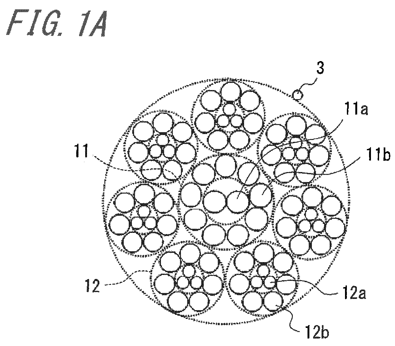
- FIGS. 1A and 1B are cross-sectional diagrams, in a direction orthogonal to the longitudinal direction of the steel cord, illustrating configuration examples of the steel cord for reinforcing a rubber article according to this disclosure.
- the cord illustrated in FIG. 1A is formed from one core strand 11 and a plurality (seven in the illustrated example) of sheath strands 12.
- the core strand 11 has a two-layer twisted layer structure formed by intertwining a plurality of steel filaments 11a, 11b, and the sheath strands 12 each have a twisted layer structure (a two-layer twisted layer structure in the illustrated example) formed by intertwining a plurality of steel filaments 12a, 12b.
- the sheath strands 12 are intertwined around the core strand 11, thus giving the cord a multi-twisted structure.
- the core strand 11 in this example has a 2 + 9 structure with a core comprising two intertwined core filaments 11a, nine sheath filaments 11b being intertwined around the core to form a sheath
- each sheath strand 12 in this example has a 3 + 7 structure with a core comprising three core filaments 12a, seven sheath filaments 12b being intertwined around the core to form a sheath.
- a wrapping filament 3 is wrapped spirally around the outer circumference of the sheath strands 12 in the illustrated cord.
- the diameter of the outermost layer sheath filaments 12b forming the outermost layer sheath of each sheath strand is greater than the diameter of each filament 12a inside the outermost layer sheath of the sheath strand.
- the cord illustrated in FIG. 1B is formed from one core strand 21 and a plurality, seven in the illustrated example, of sheath strands 22.
- the core strand 21 has a two-layer twisted layer structure formed by intertwining a plurality of steel filaments 21 a, 21b, and the sheath strands 22 each have a twisted layer structure (a two-layer twisted layer structure in the illustrated example) formed by intertwining a plurality of steel filaments 22a, 22b.
- the sheath strands 22 are intertwined around the core strand 21, thus giving the cord a multi-twisted structure.
- the core strand 21 in this example has a 2 + 9 structure with a core comprising two intertwined core filaments 21 a, nine sheath filaments 21b being intertwined around the core to form a sheath, and each sheath strand 22 in this example has a 3 + 8 structure with a core comprising three core filaments 22a, eight sheath filaments 22b being intertwined around the core to form a sheath.
- a wrapping filament 3 is wrapped spirally around the outer circumference of the sheath strands 22 in the illustrated cord.
- the diameter of the outermost layer sheath filaments 22b forming the outermost layer sheath of each sheath strand is greater than the diameter of each filament 22a inside the outermost layer sheath of the sheath strand.
- the core strands 11, 21 be formed by two core filaments 11a, 21 a, and that the diameter of the outermost layer sheath filaments 12b, 22b forming the outermost layer sheath of each sheath strand 12, 22 be greater than the diameter of each filament 12a, 22a inside the outermost layer sheath of the sheath strand 12, 22.
- the core strand positioned at the center of the cord it is important to suppress the concentration of stress at the outermost layer filaments.
- the diameter of the outermost layer sheath filaments 12b, 22b forming the outermost layer sheath of each sheath strand 12, 22 be greater than the diameter of each filament 12a, 22a inside the outermost layer sheaths.
- the contact area with the outermost layer sheath filaments of the core strand can be increased without increasing the diameter of the strands themselves.
- the load of the tightening force when an input force occurs can thus be widely born, and the concentration of stress can be eased. Since the resistance to the tightening force is increased by using two core filaments for the core strand, the stress distribution of the cord as a whole becomes optimal, and the anti-cut resistance of the cord increases.
- the diameter of the inner layer filaments of the sheath strand is also possible to set the diameter of the inner layer filaments of the sheath strand to be smaller than the diameter of the outermost layer sheath filaments so as to improve the anti-cut resistance of the cord while avoiding an increase in the diameter and the weight of the cord.
- the number of sheath strands 12, 22 is preferably from seven to nine.
- the diameter of the sheath strands 12, 22 is set to be less than the diameter of the core strand 11, 21, allowing an arrangement with seven to nine of the sheath strands 12, as illustrated in FIG. 1 .
- the number of sheath filaments 11b, 21b forming the sheath of the core strand 11, 21 is preferably set to six or greater. Setting the number to nine, however, as in the above configuration example, is particularly preferable in order to suppress early breakage, since a wire diameter with a certain thickness can be ensured.
- the number of core filaments 12a, 22a of the sheath strands 12, 22 is preferably three in order to improve the filling factor of steel, and the number of outermost layer sheath filaments 12b, 22b that form the outermost layer sheath is preferably at least six in order to improve the filling factor of steel. Setting the number of outermost layer sheath filaments 12b, 22b to be seven or eight, however, as in the above configuration example, is particularly preferable in order to suppress early breakage, since a wire diameter with a certain thickness can be ensured.
- the filaments forming the core strand 11, 21 preferably all have the same diameter.
- the anti-cut resistance can also be improved by making the core filaments 11 a, 21 a smaller in diameter than the sheath filaments 11b, 21b in the core strand 11, 21, but in order to ensure enough space to arrange the sheath filaments, all of the filaments forming the core strand preferably have the same diameter.
- the cord diameter of the cord of this disclosure is preferably 4 mm or greater.
- the cord diameter of the cord of this disclosure is preferably less than 5 mm.
- the cord diameter is preferably set to 4.5 mm.
- the wire diameter and tensile strength of the filaments that are used, along with the twisting direction of the filaments and strands, the twist pitch, and the like are not particularly restricted and may be selected appropriately as desired in accordance with a normal method.
- so-called high tensile strength steel with a carbon content of 0.80% by mass or greater may be used for the filaments.
- the cord of this disclosure may or may not include a wrapping filament.
- the cord of this disclosure has excellent anti-cut resistance and is therefore suitable for use as a reinforcing member in a large-sized tire used in heavy-duty vehicles such as construction and mining vehicles, in particular in an extra large off-road radial tire with a tire size of approximately 57 inches.
- a large-sized tire is normally provided with a carcass having one or more plies of steel cords extending radially between a pair of bead cores, an intersecting belt layer with at least four layers disposed outward in the tire radial direction from the crown of the carcass, and a tread disposed outward in the tire radial direction from the intersecting belt layer.
- the cords of this disclosure are, for example, used as reinforcing cords for the intersecting belt layer.
- Example 1 Example 2
- Example 3 cord structure / FIG. unit FIG. 1A FIG. 1B
- FIG. 1 Example 3
- FIG. 2A FIG. 2B FIG. 2C FIG. 2D FIG. 2E core strand structure 3+9 3+9 2+9 3+9 2+9 core filament diameter mm 0.415 0.415 0.455 0.415 0.455 sheath filament diameter mm 0.455 0.455 0.455 0.455 core strand diameter mm 1.804 1.804 1.820 1.804 1.820 strength N 4974 4974 4690 4974 4690 sheath strand structure 3+8 1+6 1+6 3+9 3+9 number of sheath strands number 7 7 7 7 7 7 core filament diameter mm 0.280 0.455 0.455 0.325 0.325 sheath filament diameter mm 0.370 0.455 0.455 0.325 0.325 sheath strand diameter mm 1.343 1.365 1.365 1.350 1.350 strength N 3223 2984 2984 3212 3212 cord diameter mm 4.49 4.53 4.55 4.51 4.52 cord strength N 27500 25900 25600 27500 27200 anti-cut resistance kN
- Comparative Example 4 in Table 2 is a steel cord with a 3 + 9 structure for both the core strand and the sheath strands, i.e. three core filaments and nine sheath filaments, and has a high steel filling density, but the value of the anti-cut resistance is 9.02 kN, which is a relatively low value.
- Comparative Example 5 the number of core filaments in the core strand of this structure was changed to two, but as described above, the balance between the anti-cut resistance of the core strand and the sheath strands was lost, and the anti-cut resistance of the cord overall decreased.
- none of Comparative Examples 1, 2, or 3 had the structure of this disclosure, and therefore the improvement in the anti-cut resistance was insufficient.
- the anti-cut resistance was improved while avoiding an increase in the diameter and weight of the steel cord in the cord of each Example in Table 1 satisfying the following conditions: using two core filaments to form the core of the core strand, and setting the sheath filament diameter of the sheath strands to be greater than the core filament diameter.
Landscapes
- Engineering & Computer Science (AREA)
- Mechanical Engineering (AREA)
- Ropes Or Cables (AREA)
- Tires In General (AREA)
Abstract
Description
- This disclosure relates to a steel cord for reinforcing a rubber article and to a pneumatic tire using the steel cord (also referred to below simply as a "cord" and a "tire").
- In rubber articles, such as tires, steel cords formed by intertwining a plurality of steel filaments are widely used as a reinforcing member. In particular, a tire that is used in heavy-duty vehicles such as construction and mining vehicles is used under a large load on highly uneven, rough terrain and the like. Therefore, the steel cords that act as the reinforcing member in particular need to have high strength and durability. Hence, in such large-sized tires, steel cords with a so-called multi-twisted structure are adopted, yielded by further intertwining a plurality of strands that are each formed by intertwining a plurality of steel filaments.
- In the case of a multi-twisted structure steel cord, the outermost layer sheath filaments of the core strand and the sheath strands come into rough contact with each other due to cord tension occurring when the tire is used, or due to a cut input when the tire rolls over a blunt or sharp projection. Because of stress concentrating at the point of contact, the filaments may undergo early shear failure.
- As an approach for solving this problem, for example
JP H11-21775 A - PTL 1:
JP H11-21775 A - With demand in recent years for better tire performance, however, there has been a demand for an increase in the anti-cut resistance of a steel cord for reinforcing a rubber article. On the other hand, in order to decrease the burden on the environment, there has been increasing demand in recent years for reducing the weight of tires as well. Therefore, it is desirable to further improve tire performance while avoiding an increase in the diameter and weight of the steel cord.
- Therefore, it would be helpful to provide a steel cord for reinforcing a rubber article, and a pneumatic tire using the steel cord, that can improve the anti-cut resistance when the steel cord is applied to rubber articles such as tires, while avoiding an increase in the diameter and weight of the steel cord.
- A steel cord for reinforcing a rubber article according to this disclosure comprises:
- one core strand having a two-layer twisted layer structure formed by intertwining a plurality of steel filaments; and
- a plurality of sheath strands having a twisted layer structure formed by intertwining a plurality of steel filaments;
- wherein the sheath strands are intertwined around the core strand; and
- wherein a core of the core strand is formed by two core filaments, and a diameter of outermost layer sheath filaments forming an outermost layer sheath of each sheath strand is greater than a diameter of a filament inside the outermost layer sheath of the sheath strand.
- According to the steel cord for reinforcing a rubber article of this disclosure, the anti-cut resistance can be improved when the steel cord is applied to rubber articles such as tires, while avoiding an increase in the diameter and weight of the steel cord.
- According to this disclosure, it is possible to provide a steel cord for reinforcing a rubber article, and a pneumatic tire using the steel cord, that can improve the anti-cut resistance when the steel cord is applied to rubber articles such as tires, while avoiding an increase in the diameter and weight of the steel cord.
- In the accompanying drawings:
-
FIGS. 1A and 1B are cross-sectional diagrams, in a direction orthogonal to the longitudinal direction of the steel cord, illustrating configuration examples of the steel cord for reinforcing a rubber article according to this disclosure (Examples 1 to 3); and -
FIGS. 2A and 2B are cross-sectional diagrams, in a direction orthogonal to the longitudinal direction of the steel cord, illustrating a steel cord for reinforcing a rubber article according to Comparative Examples (Comparative Examples 1 to 5). - The following describes embodiments for implementing this disclosure.
-
FIGS. 1A and 1B are cross-sectional diagrams, in a direction orthogonal to the longitudinal direction of the steel cord, illustrating configuration examples of the steel cord for reinforcing a rubber article according to this disclosure. The cord illustrated inFIG. 1A is formed from onecore strand 11 and a plurality (seven in the illustrated example) ofsheath strands 12. Thecore strand 11 has a two-layer twisted layer structure formed by intertwining a plurality ofsteel filaments sheath strands 12 each have a twisted layer structure (a two-layer twisted layer structure in the illustrated example) formed by intertwining a plurality ofsteel filaments sheath strands 12 are intertwined around thecore strand 11, thus giving the cord a multi-twisted structure. In the illustrated cord, thecore strand 11 in this example has a 2 + 9 structure with a core comprising two intertwinedcore filaments 11a, ninesheath filaments 11b being intertwined around the core to form a sheath, and eachsheath strand 12 in this example has a 3 + 7 structure with a core comprising threecore filaments 12a, sevensheath filaments 12b being intertwined around the core to form a sheath. While not an essential feature, awrapping filament 3 is wrapped spirally around the outer circumference of thesheath strands 12 in the illustrated cord. Here, the diameter of the outermostlayer sheath filaments 12b forming the outermost layer sheath of each sheath strand is greater than the diameter of eachfilament 12a inside the outermost layer sheath of the sheath strand. - The cord illustrated in
FIG. 1B is formed from onecore strand 21 and a plurality, seven in the illustrated example, ofsheath strands 22. Thecore strand 21 has a two-layer twisted layer structure formed by intertwining a plurality ofsteel filaments sheath strands 22 each have a twisted layer structure (a two-layer twisted layer structure in the illustrated example) formed by intertwining a plurality ofsteel filaments sheath strands 22 are intertwined around thecore strand 21, thus giving the cord a multi-twisted structure. In the illustrated cord, thecore strand 21 in this example has a 2 + 9 structure with a core comprising two intertwinedcore filaments 21 a, ninesheath filaments 21b being intertwined around the core to form a sheath, and eachsheath strand 22 in this example has a 3 + 8 structure with a core comprising threecore filaments 22a, eightsheath filaments 22b being intertwined around the core to form a sheath. While not an essential feature, awrapping filament 3 is wrapped spirally around the outer circumference of thesheath strands 22 in the illustrated cord. Here, the diameter of the outermostlayer sheath filaments 22b forming the outermost layer sheath of each sheath strand is greater than the diameter of eachfilament 22a inside the outermost layer sheath of the sheath strand. - In this disclosure, it is important that the
core strands core filaments layer sheath filaments sheath strand filament sheath strand sheath strands - It is also important that the diameter of the outermost
layer sheath filaments sheath strand filament - Accordingly, for example it is also possible to set the diameter of the inner layer filaments of the sheath strand to be smaller than the diameter of the outermost layer sheath filaments so as to improve the anti-cut resistance of the cord while avoiding an increase in the diameter and the weight of the cord.
- In the cord of this disclosure, the number of
sheath strands sheath strands core strand sheath strands 12, as illustrated inFIG. 1 . By setting the number ofsheath strands 12 to be seven to nine, the tightening force of the sheath strands on the core strand can be reduced, improving the anti-cut resistance of the cord. - Furthermore, in order to improve the filling factor of steel, the number of
sheath filaments core strand - The number of
core filaments sheath strands layer sheath filaments layer sheath filaments - In the cords of this disclosure, the filaments forming the
core strand core filaments sheath filaments core strand - Furthermore, the cord diameter of the cord of this disclosure is preferably 4 mm or greater. By forming the cord with a thick diameter of 4 mm or greater, in particular the strength and the anti-cut resistance that are required for a large-sized tire used in heavy-duty vehicles such as construction vehicles can both be guaranteed. Also, the cord diameter of the cord of this disclosure is preferably less than 5 mm. By setting the cord diameter to be less than 5 mm, an increase in weight of the tire can be effectively suppressed. In particular, the cord diameter is preferably set to 4.5 mm.
- In the cords of this disclosure, the wire diameter and tensile strength of the filaments that are used, along with the twisting direction of the filaments and strands, the twist pitch, and the like are not particularly restricted and may be selected appropriately as desired in accordance with a normal method. For example, so-called high tensile strength steel with a carbon content of 0.80% by mass or greater may be used for the filaments. The cord of this disclosure may or may not include a wrapping filament.
- The cord of this disclosure has excellent anti-cut resistance and is therefore suitable for use as a reinforcing member in a large-sized tire used in heavy-duty vehicles such as construction and mining vehicles, in particular in an extra large off-road radial tire with a tire size of approximately 57 inches. Such a large-sized tire is normally provided with a carcass having one or more plies of steel cords extending radially between a pair of bead cores, an intersecting belt layer with at least four layers disposed outward in the tire radial direction from the crown of the carcass, and a tread disposed outward in the tire radial direction from the intersecting belt layer. In such a tire, the cords of this disclosure are, for example, used as reinforcing cords for the intersecting belt layer.
- The following provides a detailed explanation with Examples, but this disclosure is in no way limited to the following Examples.
- As shown in the tables below, a plurality of steel cords for a rubber article were produced with a multi-twisted structure while changing the number and the wire diameter of the filaments in the core strand and the sheath strands. The tables below also list the results of the following evaluations on the cords that were obtained. In the following tables, the "cord strength" was measured with the JIS G3525 method for testing breaking force with regard to tensile tests.
- For each cord that was obtained, the anti-cut resistance was evaluated using a Charpy impact tester. The anti-cut resistance was evaluated based on the force necessary for the cord to break by dropping a blade-shaped weight thereon. A larger numerical value indicates superior anti-cut resistance and is therefore better.
[Table 1] Example 1 Example 2 Example 3 cord structure / FIG. unit FIG. 1A FIG. 1B FIG. 1B core strand structure 2+9 2+9 2+9 core filament diameter mm 0.455 0.455 0.480 sheath filament diameter mm 0.455 0.455 0.480 core strand diameter mm 1.820 1.820 1.920 strength N 4690 4690 5012 sheath strand structure 3+7 3+8 3+8 number of sheath strands number 7 7 7 core filament diameter mm 0.255 0.280 0.275 sheath filament diameter mm 0.415 0.370 0.365 sheath strand diameter mm 1.379 1.343 1.323 strength N 3195 3223 3160 cord diameter mm 4.58 4.51 4.57 cord strength N 27100 27300 27100 anti-cut resistance kN 10.26 10.22 10.20 cord weight g/m 77 74 74 [Table 2] Comparative Example 1 Comparative Example 2 Comparative Example 3 Comparative Example 4 Comparative Example 5 cord structure / FIG. unit FIG. 2A FIG. 2B FIG. 2C FIG. 2D FIG. 2E core strand structure 3+9 3+9 2+9 3+9 2+9 core filament diameter mm 0.415 0.415 0.455 0.415 0.455 sheath filament diameter mm 0.455 0.455 0.455 0.455 0.455 core strand diameter mm 1.804 1.804 1.820 1.804 1.820 strength N 4974 4974 4690 4974 4690 sheath strand structure 3+8 1+6 1+6 3+9 3+9 number of sheath strands number 7 7 7 7 7 core filament diameter mm 0.280 0.455 0.455 0.325 0.325 sheath filament diameter mm 0.370 0.455 0.455 0.325 0.325 sheath strand diameter mm 1.343 1.365 1.365 1.350 1.350 strength N 3223 2984 2984 3212 3212 cord diameter mm 4.49 4.53 4.55 4.51 4.52 cord strength N 27500 25900 25600 27500 27200 anti-cut resistance kN 9.83 9.62 9.41 9.02 8.86 cord weight g/m 75 79 78 72 71 - Comparative Example 4 in Table 2 is a steel cord with a 3 + 9 structure for both the core strand and the sheath strands, i.e. three core filaments and nine sheath filaments, and has a high steel filling density, but the value of the anti-cut resistance is 9.02 kN, which is a relatively low value. In Comparative Example 5, the number of core filaments in the core strand of this structure was changed to two, but as described above, the balance between the anti-cut resistance of the core strand and the sheath strands was lost, and the anti-cut resistance of the cord overall decreased. As for the other Comparative Examples, none of Comparative Examples 1, 2, or 3 had the structure of this disclosure, and therefore the improvement in the anti-cut resistance was insufficient.
- By contrast, the anti-cut resistance was improved while avoiding an increase in the diameter and weight of the steel cord in the cord of each Example in Table 1 satisfying the following conditions: using two core filaments to form the core of the core strand, and setting the sheath filament diameter of the sheath strands to be greater than the core filament diameter.
-
- 11, 21
- Core strand
- 12, 22
- Sheath strand
- 11a, 12a, 21a, 22a
- Core filament
- 11b, 21b
- Sheath filament
- 12b, 22b
- Sheath filament (outermost layer sheath filament)
- 3
- Wrapping filament
Claims (8)
- A steel cord for reinforcing a rubber article, the steel cord comprising:one core strand having a two-layer twisted layer structure formed by intertwining a plurality of steel filaments; anda plurality of sheath strands having a twisted layer structure formed by intertwining a plurality of steel filaments;wherein the sheath strands are intertwined around the core strand; andwherein a core of the core strand is formed by two core filaments, and a diameter of outermost layer sheath filaments forming an outermost layer sheath of each sheath strand is greater than a diameter of a filament inside the outermost layer sheath of the sheath strand.
- The steel cord for reinforcing a rubber article of claim 1, wherein the plurality of sheath strands comprises 7 to 9 sheath strands.
- The steel cord for reinforcing a rubber article of claim 1 or 2, wherein the core strand has a 2 + 9 structure with the core of the core strand comprising two core filaments, nine sheath filaments being intertwined around the core of the core strand to form a sheath.
- The steel cord for reinforcing a rubber article of any one of claims 1 to 3, wherein each sheath strand has a 3 + 7 structure or a 3 + 8 structure with a core of the sheath strand comprising three core filaments, seven or eight sheath filaments being intertwined around the core of the sheath strand to form a sheath.
- The steel cord for reinforcing a rubber article of any one of claims 1 to 4, wherein each filament forming the core strand has an identical diameter.
- The steel cord for reinforcing a rubber article of any one of claims 1 to 5, wherein a diameter of the steel cord is 4 mm or greater.
- The steel cord for reinforcing a rubber article of any one of claims 1 to 6, wherein a diameter of the steel cord is less than 5 mm.
- A pneumatic tire comprising the steel cord for reinforcing a rubber article of any one of claims 1 to 7.
Applications Claiming Priority (2)
| Application Number | Priority Date | Filing Date | Title |
|---|---|---|---|
| JP2014203198A JP6545942B2 (en) | 2014-10-01 | 2014-10-01 | Steel cord for reinforcing rubber articles and pneumatic tire using the same |
| PCT/JP2015/004479 WO2016051669A1 (en) | 2014-10-01 | 2015-09-03 | Steel cord for reinforcing rubber article, and pneumatic tire using same |
Publications (3)
| Publication Number | Publication Date |
|---|---|
| EP3202977A1 true EP3202977A1 (en) | 2017-08-09 |
| EP3202977A4 EP3202977A4 (en) | 2017-10-18 |
| EP3202977B1 EP3202977B1 (en) | 2020-01-29 |
Family
ID=55629748
Family Applications (1)
| Application Number | Title | Priority Date | Filing Date |
|---|---|---|---|
| EP15846966.8A Active EP3202977B1 (en) | 2014-10-01 | 2015-09-03 | Steel cord for reinforcing rubber article, and pneumatic tire using same |
Country Status (6)
| Country | Link |
|---|---|
| US (1) | US10105991B2 (en) |
| EP (1) | EP3202977B1 (en) |
| JP (1) | JP6545942B2 (en) |
| CN (1) | CN106715790A (en) |
| ES (1) | ES2787219T3 (en) |
| WO (1) | WO2016051669A1 (en) |
Families Citing this family (9)
| Publication number | Priority date | Publication date | Assignee | Title |
|---|---|---|---|---|
| JP2018080414A (en) * | 2016-11-15 | 2018-05-24 | 株式会社ブリヂストン | Steel code for reinforcing rubber article, and rubber crawler and tire using the same |
| CN110546324B (en) * | 2017-04-28 | 2022-02-18 | 株式会社普利司通 | Steel cord for reinforcing rubber article, method for producing same, and tire |
| JP6936059B2 (en) | 2017-06-30 | 2021-09-15 | 株式会社ブリヂストン | Steel cord for reinforcing rubber articles |
| WO2019081412A1 (en) * | 2017-10-27 | 2019-05-02 | Bekaert Advanced Cords Aalter Nv | Belt comprising steel cords adapted for wear detection |
| JP6892374B2 (en) * | 2017-12-15 | 2021-06-23 | 株式会社ブリヂストン | Steel cords and tires for reinforcing rubber articles |
| FR3103201A1 (en) | 2019-11-15 | 2021-05-21 | Compagnie Generale Des Etablissements Michelin | Two-layer multi-strand cable with improved performance sheathed inner layer |
| EP4058627B1 (en) | 2019-11-15 | 2025-12-31 | Compagnie Generale Des Etablissements Michelin | Multi-strand cable with two layers, sheathed inner layer, and improved penetration. |
| FR3115799B1 (en) | 2020-11-05 | 2022-10-14 | Michelin & Cie | Two-layer multi-strand cable with sheathed inner layer with improved penetrability |
| EP4561673A1 (en) * | 2022-07-29 | 2025-06-04 | Foundry Innovation & Research 1, Ltd. | Multistranded conductors adapted to dynamic in vivo environments |
Family Cites Families (23)
| Publication number | Priority date | Publication date | Assignee | Title |
|---|---|---|---|---|
| NL124080C (en) | 1959-08-11 | |||
| BE654920A (en) * | 1964-10-28 | 1965-02-15 | ||
| GB8424086D0 (en) * | 1984-09-24 | 1984-10-31 | Bekaert Sa Nv | Steel cord |
| DE3632298A1 (en) * | 1986-09-23 | 1988-04-07 | Saar Gmbh Drahtseilwerk | WIRE ROPE FOR A HANGING INSERT OVER A LARGE HEIGHT DIFFERENCE, IN PARTICULAR CONVEYOR BASKET ROPE, DEEP ROPE ROPE OR ROPEWAY ROPE |
| JPH0827682A (en) * | 1994-07-06 | 1996-01-30 | Bridgestone Corp | Steel cord for reinforcement of rubber article and pneumatic radial tire |
| JP3709551B2 (en) | 1997-07-08 | 2005-10-26 | 株式会社ブリヂストン | Steel cord for reinforcing rubber articles and pneumatic tires |
| JP4582672B2 (en) * | 1998-10-20 | 2010-11-17 | 株式会社ブリヂストン | Pneumatic tire |
| WO2001034900A1 (en) * | 1999-11-11 | 2001-05-17 | Bridgestone Corporation | Rubber article-reinforcing steel cord and tire |
| US6272830B1 (en) * | 2000-02-18 | 2001-08-14 | The Goodyear Tire & Rubber Company | Steel cord for reinforcing elastomeric articles |
| FR2870164B1 (en) * | 2004-05-12 | 2006-07-14 | Michelin Soc Tech | PNEUMATIC AND COMPOSITE METAL / RUBBER FOR PNEUMATIC |
| JP4367846B2 (en) * | 2004-07-08 | 2009-11-18 | 株式会社ブリヂストン | Steel cords and tires for rubber article reinforcement |
| JP4799208B2 (en) * | 2005-03-11 | 2011-10-26 | 株式会社ハイレックスコーポレーション | Inner cable for operation |
| JP4963389B2 (en) | 2006-09-14 | 2012-06-27 | 株式会社ブリヂストン | Steel cords, rubber-steel cord composites and tires |
| KR100785241B1 (en) * | 2007-02-07 | 2007-12-12 | 주식회사 효성 | Steel Cords for Radial Tires |
| WO2009048054A1 (en) * | 2007-10-11 | 2009-04-16 | Bridgestone Corporation | Steel cord for rubber article reinforcement and pneumatic tire using the steel cord |
| JP2009108460A (en) * | 2007-10-11 | 2009-05-21 | Bridgestone Corp | Steel cord for rubber article reinforcement and pneumatic tire using the steel cord |
| FR2947574B1 (en) | 2009-07-03 | 2012-11-09 | Michelin Soc Tech | CABLE MULTITORONS WHOSE ELEMENTARY TORONES ARE CABLES WITH TWO LAYERS GOMMES IN SITU. |
| WO2011116493A1 (en) * | 2010-03-23 | 2011-09-29 | Nv Bekaert Sa | Open off-the-road cord with preformed filaments |
| CN103370468B (en) * | 2010-12-16 | 2015-09-02 | 株式会社普利司通 | Steel cord for reinforcing rubber article and use its pneumatic tire |
| JP5814179B2 (en) * | 2012-05-10 | 2015-11-17 | 株式会社ブリヂストン | Steel cord for reinforcing rubber articles and tire using the same |
| JP6400972B2 (en) | 2014-07-28 | 2018-10-03 | 株式会社ブリヂストン | Steel cord for rubber article reinforcement |
| ES2743486T5 (en) | 2014-07-28 | 2023-04-10 | Bridgestone Corp | Steel cord to reinforce a rubber article |
| JP6689747B2 (en) | 2014-07-28 | 2020-04-28 | 株式会社ブリヂストン | Steel cord for reinforcing rubber articles |
-
2014
- 2014-10-01 JP JP2014203198A patent/JP6545942B2/en active Active
-
2015
- 2015-09-03 CN CN201580051527.XA patent/CN106715790A/en active Pending
- 2015-09-03 EP EP15846966.8A patent/EP3202977B1/en active Active
- 2015-09-03 ES ES15846966T patent/ES2787219T3/en active Active
- 2015-09-03 US US15/504,526 patent/US10105991B2/en active Active
- 2015-09-03 WO PCT/JP2015/004479 patent/WO2016051669A1/en not_active Ceased
Also Published As
| Publication number | Publication date |
|---|---|
| EP3202977A4 (en) | 2017-10-18 |
| JP6545942B2 (en) | 2019-07-17 |
| WO2016051669A1 (en) | 2016-04-07 |
| CN106715790A (en) | 2017-05-24 |
| US20170232798A1 (en) | 2017-08-17 |
| US10105991B2 (en) | 2018-10-23 |
| EP3202977B1 (en) | 2020-01-29 |
| ES2787219T3 (en) | 2020-10-15 |
| JP2016069774A (en) | 2016-05-09 |
Similar Documents
| Publication | Publication Date | Title |
|---|---|---|
| EP3202977B1 (en) | Steel cord for reinforcing rubber article, and pneumatic tire using same | |
| US10906353B2 (en) | Steel cord for reinforcing rubber article | |
| EP3196354B1 (en) | Steel cord for reinforcing rubber article | |
| EP3196355B1 (en) | Steel cord for reinforcing rubber article | |
| US10895037B2 (en) | Steel cord for reinforcing rubber article | |
| EP2639082B1 (en) | Pneumatic tire | |
| JP2009299223A (en) | Steel cord for reinforcement of rubber product and pneumatic tire using same | |
| US10173470B2 (en) | Steel cord for reinforcing rubber article | |
| JP5083943B2 (en) | Steel cord for reinforcing rubber articles and pneumatic tire using the same | |
| JP2010090509A (en) | Steel cord for reinforcing rubber article and pneumatic tire | |
| JP6171759B2 (en) | Pneumatic radial tire | |
| JP2018176923A (en) | Pneumatic radial tire | |
| JP2011231419A (en) | Steel cord for reinforcing rubber article and tire using the same | |
| JP3187601B2 (en) | Steel cord for reinforcing rubber articles and pneumatic radial tire | |
| JP2011032596A (en) | Steel cord for reinforcing rubber article and tire | |
| JP2010064689A (en) | Pneumatic radial tire for heavy load | |
| JP2017082343A (en) | Steel cord for reinforcing rubber product, and pneumatic tire made therefrom | |
| JP2009280069A (en) | Pneumatic radial tire for heavy load |
Legal Events
| Date | Code | Title | Description |
|---|---|---|---|
| STAA | Information on the status of an ep patent application or granted ep patent |
Free format text: STATUS: THE INTERNATIONAL PUBLICATION HAS BEEN MADE |
|
| PUAI | Public reference made under article 153(3) epc to a published international application that has entered the european phase |
Free format text: ORIGINAL CODE: 0009012 |
|
| STAA | Information on the status of an ep patent application or granted ep patent |
Free format text: STATUS: REQUEST FOR EXAMINATION WAS MADE |
|
| 17P | Request for examination filed |
Effective date: 20170330 |
|
| AK | Designated contracting states |
Kind code of ref document: A1 Designated state(s): AL AT BE BG CH CY CZ DE DK EE ES FI FR GB GR HR HU IE IS IT LI LT LU LV MC MK MT NL NO PL PT RO RS SE SI SK SM TR |
|
| AX | Request for extension of the european patent |
Extension state: BA ME |
|
| A4 | Supplementary search report drawn up and despatched |
Effective date: 20170919 |
|
| RIC1 | Information provided on ipc code assigned before grant |
Ipc: B60C 9/00 20060101ALI20170913BHEP Ipc: D07B 1/06 20060101AFI20170913BHEP |
|
| DAV | Request for validation of the european patent (deleted) | ||
| DAX | Request for extension of the european patent (deleted) | ||
| GRAP | Despatch of communication of intention to grant a patent |
Free format text: ORIGINAL CODE: EPIDOSNIGR1 |
|
| STAA | Information on the status of an ep patent application or granted ep patent |
Free format text: STATUS: GRANT OF PATENT IS INTENDED |
|
| INTG | Intention to grant announced |
Effective date: 20190912 |
|
| GRAS | Grant fee paid |
Free format text: ORIGINAL CODE: EPIDOSNIGR3 |
|
| GRAA | (expected) grant |
Free format text: ORIGINAL CODE: 0009210 |
|
| STAA | Information on the status of an ep patent application or granted ep patent |
Free format text: STATUS: THE PATENT HAS BEEN GRANTED |
|
| AK | Designated contracting states |
Kind code of ref document: B1 Designated state(s): AL AT BE BG CH CY CZ DE DK EE ES FI FR GB GR HR HU IE IS IT LI LT LU LV MC MK MT NL NO PL PT RO RS SE SI SK SM TR |
|
| REG | Reference to a national code |
Ref country code: GB Ref legal event code: FG4D |
|
| REG | Reference to a national code |
Ref country code: CH Ref legal event code: EP |
|
| REG | Reference to a national code |
Ref country code: AT Ref legal event code: REF Ref document number: 1228569 Country of ref document: AT Kind code of ref document: T Effective date: 20200215 |
|
| REG | Reference to a national code |
Ref country code: IE Ref legal event code: FG4D |
|
| REG | Reference to a national code |
Ref country code: DE Ref legal event code: R096 Ref document number: 602015046235 Country of ref document: DE |
|
| REG | Reference to a national code |
Ref country code: NL Ref legal event code: MP Effective date: 20200129 |
|
| PG25 | Lapsed in a contracting state [announced via postgrant information from national office to epo] |
Ref country code: NO Free format text: LAPSE BECAUSE OF FAILURE TO SUBMIT A TRANSLATION OF THE DESCRIPTION OR TO PAY THE FEE WITHIN THE PRESCRIBED TIME-LIMIT Effective date: 20200429 Ref country code: FI Free format text: LAPSE BECAUSE OF FAILURE TO SUBMIT A TRANSLATION OF THE DESCRIPTION OR TO PAY THE FEE WITHIN THE PRESCRIBED TIME-LIMIT Effective date: 20200129 Ref country code: RS Free format text: LAPSE BECAUSE OF FAILURE TO SUBMIT A TRANSLATION OF THE DESCRIPTION OR TO PAY THE FEE WITHIN THE PRESCRIBED TIME-LIMIT Effective date: 20200129 Ref country code: PT Free format text: LAPSE BECAUSE OF FAILURE TO SUBMIT A TRANSLATION OF THE DESCRIPTION OR TO PAY THE FEE WITHIN THE PRESCRIBED TIME-LIMIT Effective date: 20200621 |
|
| REG | Reference to a national code |
Ref country code: LT Ref legal event code: MG4D |
|
| PG25 | Lapsed in a contracting state [announced via postgrant information from national office to epo] |
Ref country code: HR Free format text: LAPSE BECAUSE OF FAILURE TO SUBMIT A TRANSLATION OF THE DESCRIPTION OR TO PAY THE FEE WITHIN THE PRESCRIBED TIME-LIMIT Effective date: 20200129 Ref country code: LV Free format text: LAPSE BECAUSE OF FAILURE TO SUBMIT A TRANSLATION OF THE DESCRIPTION OR TO PAY THE FEE WITHIN THE PRESCRIBED TIME-LIMIT Effective date: 20200129 Ref country code: SE Free format text: LAPSE BECAUSE OF FAILURE TO SUBMIT A TRANSLATION OF THE DESCRIPTION OR TO PAY THE FEE WITHIN THE PRESCRIBED TIME-LIMIT Effective date: 20200129 Ref country code: IS Free format text: LAPSE BECAUSE OF FAILURE TO SUBMIT A TRANSLATION OF THE DESCRIPTION OR TO PAY THE FEE WITHIN THE PRESCRIBED TIME-LIMIT Effective date: 20200529 Ref country code: BG Free format text: LAPSE BECAUSE OF FAILURE TO SUBMIT A TRANSLATION OF THE DESCRIPTION OR TO PAY THE FEE WITHIN THE PRESCRIBED TIME-LIMIT Effective date: 20200429 Ref country code: GR Free format text: LAPSE BECAUSE OF FAILURE TO SUBMIT A TRANSLATION OF THE DESCRIPTION OR TO PAY THE FEE WITHIN THE PRESCRIBED TIME-LIMIT Effective date: 20200430 |
|
| PG25 | Lapsed in a contracting state [announced via postgrant information from national office to epo] |
Ref country code: NL Free format text: LAPSE BECAUSE OF FAILURE TO SUBMIT A TRANSLATION OF THE DESCRIPTION OR TO PAY THE FEE WITHIN THE PRESCRIBED TIME-LIMIT Effective date: 20200129 |
|
| REG | Reference to a national code |
Ref country code: ES Ref legal event code: FG2A Ref document number: 2787219 Country of ref document: ES Kind code of ref document: T3 Effective date: 20201015 |
|
| PG25 | Lapsed in a contracting state [announced via postgrant information from national office to epo] |
Ref country code: CZ Free format text: LAPSE BECAUSE OF FAILURE TO SUBMIT A TRANSLATION OF THE DESCRIPTION OR TO PAY THE FEE WITHIN THE PRESCRIBED TIME-LIMIT Effective date: 20200129 Ref country code: SK Free format text: LAPSE BECAUSE OF FAILURE TO SUBMIT A TRANSLATION OF THE DESCRIPTION OR TO PAY THE FEE WITHIN THE PRESCRIBED TIME-LIMIT Effective date: 20200129 Ref country code: LT Free format text: LAPSE BECAUSE OF FAILURE TO SUBMIT A TRANSLATION OF THE DESCRIPTION OR TO PAY THE FEE WITHIN THE PRESCRIBED TIME-LIMIT Effective date: 20200129 Ref country code: SM Free format text: LAPSE BECAUSE OF FAILURE TO SUBMIT A TRANSLATION OF THE DESCRIPTION OR TO PAY THE FEE WITHIN THE PRESCRIBED TIME-LIMIT Effective date: 20200129 Ref country code: EE Free format text: LAPSE BECAUSE OF FAILURE TO SUBMIT A TRANSLATION OF THE DESCRIPTION OR TO PAY THE FEE WITHIN THE PRESCRIBED TIME-LIMIT Effective date: 20200129 Ref country code: DK Free format text: LAPSE BECAUSE OF FAILURE TO SUBMIT A TRANSLATION OF THE DESCRIPTION OR TO PAY THE FEE WITHIN THE PRESCRIBED TIME-LIMIT Effective date: 20200129 Ref country code: RO Free format text: LAPSE BECAUSE OF FAILURE TO SUBMIT A TRANSLATION OF THE DESCRIPTION OR TO PAY THE FEE WITHIN THE PRESCRIBED TIME-LIMIT Effective date: 20200129 |
|
| REG | Reference to a national code |
Ref country code: DE Ref legal event code: R097 Ref document number: 602015046235 Country of ref document: DE |
|
| REG | Reference to a national code |
Ref country code: AT Ref legal event code: MK05 Ref document number: 1228569 Country of ref document: AT Kind code of ref document: T Effective date: 20200129 |
|
| PLBE | No opposition filed within time limit |
Free format text: ORIGINAL CODE: 0009261 |
|
| STAA | Information on the status of an ep patent application or granted ep patent |
Free format text: STATUS: NO OPPOSITION FILED WITHIN TIME LIMIT |
|
| 26N | No opposition filed |
Effective date: 20201030 |
|
| PG25 | Lapsed in a contracting state [announced via postgrant information from national office to epo] |
Ref country code: AT Free format text: LAPSE BECAUSE OF FAILURE TO SUBMIT A TRANSLATION OF THE DESCRIPTION OR TO PAY THE FEE WITHIN THE PRESCRIBED TIME-LIMIT Effective date: 20200129 Ref country code: IT Free format text: LAPSE BECAUSE OF FAILURE TO SUBMIT A TRANSLATION OF THE DESCRIPTION OR TO PAY THE FEE WITHIN THE PRESCRIBED TIME-LIMIT Effective date: 20200129 |
|
| PG25 | Lapsed in a contracting state [announced via postgrant information from national office to epo] |
Ref country code: PL Free format text: LAPSE BECAUSE OF FAILURE TO SUBMIT A TRANSLATION OF THE DESCRIPTION OR TO PAY THE FEE WITHIN THE PRESCRIBED TIME-LIMIT Effective date: 20200129 Ref country code: SI Free format text: LAPSE BECAUSE OF FAILURE TO SUBMIT A TRANSLATION OF THE DESCRIPTION OR TO PAY THE FEE WITHIN THE PRESCRIBED TIME-LIMIT Effective date: 20200129 |
|
| REG | Reference to a national code |
Ref country code: DE Ref legal event code: R119 Ref document number: 602015046235 Country of ref document: DE |
|
| REG | Reference to a national code |
Ref country code: CH Ref legal event code: PL |
|
| GBPC | Gb: european patent ceased through non-payment of renewal fee |
Effective date: 20200903 |
|
| REG | Reference to a national code |
Ref country code: BE Ref legal event code: MM Effective date: 20200930 |
|
| PG25 | Lapsed in a contracting state [announced via postgrant information from national office to epo] |
Ref country code: LU Free format text: LAPSE BECAUSE OF NON-PAYMENT OF DUE FEES Effective date: 20200903 |
|
| PG25 | Lapsed in a contracting state [announced via postgrant information from national office to epo] |
Ref country code: DE Free format text: LAPSE BECAUSE OF NON-PAYMENT OF DUE FEES Effective date: 20210401 |
|
| PG25 | Lapsed in a contracting state [announced via postgrant information from national office to epo] |
Ref country code: BE Free format text: LAPSE BECAUSE OF NON-PAYMENT OF DUE FEES Effective date: 20200930 Ref country code: CH Free format text: LAPSE BECAUSE OF NON-PAYMENT OF DUE FEES Effective date: 20200930 Ref country code: IE Free format text: LAPSE BECAUSE OF NON-PAYMENT OF DUE FEES Effective date: 20200903 Ref country code: GB Free format text: LAPSE BECAUSE OF NON-PAYMENT OF DUE FEES Effective date: 20200903 Ref country code: LI Free format text: LAPSE BECAUSE OF NON-PAYMENT OF DUE FEES Effective date: 20200930 |
|
| PG25 | Lapsed in a contracting state [announced via postgrant information from national office to epo] |
Ref country code: TR Free format text: LAPSE BECAUSE OF FAILURE TO SUBMIT A TRANSLATION OF THE DESCRIPTION OR TO PAY THE FEE WITHIN THE PRESCRIBED TIME-LIMIT Effective date: 20200129 Ref country code: MT Free format text: LAPSE BECAUSE OF FAILURE TO SUBMIT A TRANSLATION OF THE DESCRIPTION OR TO PAY THE FEE WITHIN THE PRESCRIBED TIME-LIMIT Effective date: 20200129 Ref country code: CY Free format text: LAPSE BECAUSE OF FAILURE TO SUBMIT A TRANSLATION OF THE DESCRIPTION OR TO PAY THE FEE WITHIN THE PRESCRIBED TIME-LIMIT Effective date: 20200129 |
|
| PG25 | Lapsed in a contracting state [announced via postgrant information from national office to epo] |
Ref country code: MK Free format text: LAPSE BECAUSE OF FAILURE TO SUBMIT A TRANSLATION OF THE DESCRIPTION OR TO PAY THE FEE WITHIN THE PRESCRIBED TIME-LIMIT Effective date: 20200129 Ref country code: MC Free format text: LAPSE BECAUSE OF FAILURE TO SUBMIT A TRANSLATION OF THE DESCRIPTION OR TO PAY THE FEE WITHIN THE PRESCRIBED TIME-LIMIT Effective date: 20200129 Ref country code: AL Free format text: LAPSE BECAUSE OF FAILURE TO SUBMIT A TRANSLATION OF THE DESCRIPTION OR TO PAY THE FEE WITHIN THE PRESCRIBED TIME-LIMIT Effective date: 20200129 |
|
| P01 | Opt-out of the competence of the unified patent court (upc) registered |
Effective date: 20230531 |
|
| PGFP | Annual fee paid to national office [announced via postgrant information from national office to epo] |
Ref country code: FR Payment date: 20250922 Year of fee payment: 11 |
|
| PGFP | Annual fee paid to national office [announced via postgrant information from national office to epo] |
Ref country code: ES Payment date: 20251028 Year of fee payment: 11 |