EP3202946A1 - Forming aluminide coating using metal alloy gravel - Google Patents
Forming aluminide coating using metal alloy gravel Download PDFInfo
- Publication number
- EP3202946A1 EP3202946A1 EP17153434.0A EP17153434A EP3202946A1 EP 3202946 A1 EP3202946 A1 EP 3202946A1 EP 17153434 A EP17153434 A EP 17153434A EP 3202946 A1 EP3202946 A1 EP 3202946A1
- Authority
- EP
- European Patent Office
- Prior art keywords
- component
- metal alloy
- coating
- gravel
- aluminum
- Prior art date
- Legal status (The legal status is an assumption and is not a legal conclusion. Google has not performed a legal analysis and makes no representation as to the accuracy of the status listed.)
- Granted
Links
Images



Classifications
-
- C—CHEMISTRY; METALLURGY
- C23—COATING METALLIC MATERIAL; COATING MATERIAL WITH METALLIC MATERIAL; CHEMICAL SURFACE TREATMENT; DIFFUSION TREATMENT OF METALLIC MATERIAL; COATING BY VACUUM EVAPORATION, BY SPUTTERING, BY ION IMPLANTATION OR BY CHEMICAL VAPOUR DEPOSITION, IN GENERAL; INHIBITING CORROSION OF METALLIC MATERIAL OR INCRUSTATION IN GENERAL
- C23C—COATING METALLIC MATERIAL; COATING MATERIAL WITH METALLIC MATERIAL; SURFACE TREATMENT OF METALLIC MATERIAL BY DIFFUSION INTO THE SURFACE, BY CHEMICAL CONVERSION OR SUBSTITUTION; COATING BY VACUUM EVAPORATION, BY SPUTTERING, BY ION IMPLANTATION OR BY CHEMICAL VAPOUR DEPOSITION, IN GENERAL
- C23C10/00—Solid state diffusion of only metal elements or silicon into metallic material surfaces
- C23C10/28—Solid state diffusion of only metal elements or silicon into metallic material surfaces using solids, e.g. powders, pastes
- C23C10/34—Embedding in a powder mixture, i.e. pack cementation
- C23C10/36—Embedding in a powder mixture, i.e. pack cementation only one element being diffused
- C23C10/48—Aluminising
-
- C—CHEMISTRY; METALLURGY
- C22—METALLURGY; FERROUS OR NON-FERROUS ALLOYS; TREATMENT OF ALLOYS OR NON-FERROUS METALS
- C22F—CHANGING THE PHYSICAL STRUCTURE OF NON-FERROUS METALS AND NON-FERROUS ALLOYS
- C22F1/00—Changing the physical structure of non-ferrous metals or alloys by heat treatment or by hot or cold working
- C22F1/04—Changing the physical structure of non-ferrous metals or alloys by heat treatment or by hot or cold working of aluminium or alloys based thereon
-
- C—CHEMISTRY; METALLURGY
- C23—COATING METALLIC MATERIAL; COATING MATERIAL WITH METALLIC MATERIAL; CHEMICAL SURFACE TREATMENT; DIFFUSION TREATMENT OF METALLIC MATERIAL; COATING BY VACUUM EVAPORATION, BY SPUTTERING, BY ION IMPLANTATION OR BY CHEMICAL VAPOUR DEPOSITION, IN GENERAL; INHIBITING CORROSION OF METALLIC MATERIAL OR INCRUSTATION IN GENERAL
- C23C—COATING METALLIC MATERIAL; COATING MATERIAL WITH METALLIC MATERIAL; SURFACE TREATMENT OF METALLIC MATERIAL BY DIFFUSION INTO THE SURFACE, BY CHEMICAL CONVERSION OR SUBSTITUTION; COATING BY VACUUM EVAPORATION, BY SPUTTERING, BY ION IMPLANTATION OR BY CHEMICAL VAPOUR DEPOSITION, IN GENERAL
- C23C10/00—Solid state diffusion of only metal elements or silicon into metallic material surfaces
- C23C10/04—Diffusion into selected surface areas, e.g. using masks
-
- C—CHEMISTRY; METALLURGY
- C23—COATING METALLIC MATERIAL; COATING MATERIAL WITH METALLIC MATERIAL; CHEMICAL SURFACE TREATMENT; DIFFUSION TREATMENT OF METALLIC MATERIAL; COATING BY VACUUM EVAPORATION, BY SPUTTERING, BY ION IMPLANTATION OR BY CHEMICAL VAPOUR DEPOSITION, IN GENERAL; INHIBITING CORROSION OF METALLIC MATERIAL OR INCRUSTATION IN GENERAL
- C23C—COATING METALLIC MATERIAL; COATING MATERIAL WITH METALLIC MATERIAL; SURFACE TREATMENT OF METALLIC MATERIAL BY DIFFUSION INTO THE SURFACE, BY CHEMICAL CONVERSION OR SUBSTITUTION; COATING BY VACUUM EVAPORATION, BY SPUTTERING, BY ION IMPLANTATION OR BY CHEMICAL VAPOUR DEPOSITION, IN GENERAL
- C23C10/00—Solid state diffusion of only metal elements or silicon into metallic material surfaces
- C23C10/28—Solid state diffusion of only metal elements or silicon into metallic material surfaces using solids, e.g. powders, pastes
- C23C10/34—Embedding in a powder mixture, i.e. pack cementation
- C23C10/52—Embedding in a powder mixture, i.e. pack cementation more than one element being diffused in one step
-
- C—CHEMISTRY; METALLURGY
- C23—COATING METALLIC MATERIAL; COATING MATERIAL WITH METALLIC MATERIAL; CHEMICAL SURFACE TREATMENT; DIFFUSION TREATMENT OF METALLIC MATERIAL; COATING BY VACUUM EVAPORATION, BY SPUTTERING, BY ION IMPLANTATION OR BY CHEMICAL VAPOUR DEPOSITION, IN GENERAL; INHIBITING CORROSION OF METALLIC MATERIAL OR INCRUSTATION IN GENERAL
- C23C—COATING METALLIC MATERIAL; COATING MATERIAL WITH METALLIC MATERIAL; SURFACE TREATMENT OF METALLIC MATERIAL BY DIFFUSION INTO THE SURFACE, BY CHEMICAL CONVERSION OR SUBSTITUTION; COATING BY VACUUM EVAPORATION, BY SPUTTERING, BY ION IMPLANTATION OR BY CHEMICAL VAPOUR DEPOSITION, IN GENERAL
- C23C10/00—Solid state diffusion of only metal elements or silicon into metallic material surfaces
- C23C10/28—Solid state diffusion of only metal elements or silicon into metallic material surfaces using solids, e.g. powders, pastes
- C23C10/34—Embedding in a powder mixture, i.e. pack cementation
- C23C10/52—Embedding in a powder mixture, i.e. pack cementation more than one element being diffused in one step
- C23C10/54—Diffusion of at least chromium
- C23C10/56—Diffusion of at least chromium and at least aluminium
-
- C—CHEMISTRY; METALLURGY
- C23—COATING METALLIC MATERIAL; COATING MATERIAL WITH METALLIC MATERIAL; CHEMICAL SURFACE TREATMENT; DIFFUSION TREATMENT OF METALLIC MATERIAL; COATING BY VACUUM EVAPORATION, BY SPUTTERING, BY ION IMPLANTATION OR BY CHEMICAL VAPOUR DEPOSITION, IN GENERAL; INHIBITING CORROSION OF METALLIC MATERIAL OR INCRUSTATION IN GENERAL
- C23C—COATING METALLIC MATERIAL; COATING MATERIAL WITH METALLIC MATERIAL; SURFACE TREATMENT OF METALLIC MATERIAL BY DIFFUSION INTO THE SURFACE, BY CHEMICAL CONVERSION OR SUBSTITUTION; COATING BY VACUUM EVAPORATION, BY SPUTTERING, BY ION IMPLANTATION OR BY CHEMICAL VAPOUR DEPOSITION, IN GENERAL
- C23C10/00—Solid state diffusion of only metal elements or silicon into metallic material surfaces
- C23C10/60—After-treatment
-
- C—CHEMISTRY; METALLURGY
- C23—COATING METALLIC MATERIAL; COATING MATERIAL WITH METALLIC MATERIAL; CHEMICAL SURFACE TREATMENT; DIFFUSION TREATMENT OF METALLIC MATERIAL; COATING BY VACUUM EVAPORATION, BY SPUTTERING, BY ION IMPLANTATION OR BY CHEMICAL VAPOUR DEPOSITION, IN GENERAL; INHIBITING CORROSION OF METALLIC MATERIAL OR INCRUSTATION IN GENERAL
- C23C—COATING METALLIC MATERIAL; COATING MATERIAL WITH METALLIC MATERIAL; SURFACE TREATMENT OF METALLIC MATERIAL BY DIFFUSION INTO THE SURFACE, BY CHEMICAL CONVERSION OR SUBSTITUTION; COATING BY VACUUM EVAPORATION, BY SPUTTERING, BY ION IMPLANTATION OR BY CHEMICAL VAPOUR DEPOSITION, IN GENERAL
- C23C24/00—Coating starting from inorganic powder
- C23C24/08—Coating starting from inorganic powder by application of heat or pressure and heat
Definitions
- This disclosure relates generally to coatings and, more particularly, to forming an aluminide coating on a component.
- aluminide coatings on a component Various methods are known for forming aluminide coatings on a component.
- a pack cementation method for example, aluminum from an aluminum powder surrounding the component can be heated and diffused into a base material of that component.
- Such a method may be susceptible to cracking and/or trenching.
- a method for coating a component is provided.
- the component is disposed with metal alloy gravel including aluminum.
- An aluminide coating is then formed on the component, where the aluminum from the metal alloy gravel diffuses into the component to form the aluminide coating.
- a bed of material is provided, where the bed of material includes metal alloy material and activator material.
- the metal alloy material includes cobalt and aluminum.
- the metal alloy material has an average particle size of at least about 0.125 inches (3.18 mm).
- the component is disposed with the bed of material.
- the bed of material and the component is then heated to form an aluminide coating on the component, where the aluminum from the metal alloy material diffuses into the component to form the aluminide coating.
- the component is heated to a temperature between 1200 degrees Fahrenheit and 1750 degrees Fahrenheit (649 degrees Celsius and 954 degrees Celsius).
- still another method for coating a component.
- a bed of material is provided, where the bed of material includes metal alloy material and activator material.
- the metal alloy material includes chrome and aluminum.
- the metal alloy material has an average particle size of at least about 0.125 inches (3.18 mm).
- the component is disposed with the bed of material.
- the bed of material and the component are then heated to form an aluminide coating on the component, where the aluminum from the metal alloy material diffuses into the component to form the aluminide coating.
- the component is heated to a temperature between about 1200 degrees Fahrenheit and about 1750 degrees Fahrenheit (649 degrees Celsius and 954 degrees Celsius).
- the metal alloy material may be metal alloy gravel.
- the metal alloy gravel may have an average particle size of at least about 0.125 inches (3.18 mm).
- the metal alloy gravel may also include an aluminum source such as chrome aluminum and/or cobalt aluminum.
- the method may include a step of heating the metal alloy gravel adjacent the component to a temperature between about 1200 degrees Fahrenheit and about 2000 degrees Fahrenheit (649 degrees Celsius and 1093 degrees Celsius).
- the method may include a step of heating the metal alloy gravel adjacent the component to a temperature between about 1200 degrees Fahrenheit and about 1750 degrees Fahrenheit (649 degrees Celsius and 954 degrees Celsius).
- Activator material may be disposed with the metal alloy gravel.
- the activator material may be configured as or otherwise include halide material.
- the method may include a step of heat treating the aluminide coating to provide a heat treated diffusion coating.
- the heat treating may include heating the aluminide coating to a temperature between about 1800 degrees Fahrenheit and about 2000 degrees Fahrenheit (982 degrees Celsius and 1093 degrees Celsius).
- the aluminide coating may be a green state coating.
- the heat treated diffusion coating may be a three-zone aluminide coating.
- the component may be laid on top of the metal alloy gravel.
- the component may be partially submersed in the metal alloy gravel.
- the component may be completely submersed in the metal alloy gravel.
- the method may include a step of masking a portion of the component such that the masked portion of the component is not coated with the aluminide coating.
- the component may be configured from or otherwise include a nickel alloy.
- the component may be configured as a part of a gas turbine engine.
- the component may be configured as an airfoil.
- FIG. 1 is a block diagram illustration of a system 20 for coating a component 22.
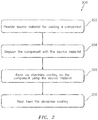
- FIG. 2 is a flow diagram of a method 200 for coating a component (e.g., 22) using a system such as, for example, the system 20 of FIG. 1 .
- the component 22 may be configured for an item of rotational equipment such as a gas turbine engine.
- This gas turbine engine may be configured in an aircraft propulsion system.
- the gas turbine engine may be configured in an auxiliary power unit for the aircraft.
- the methods and apparatuses of the present disclosure are not limited to such aircraft applications.
- the gas turbine engine may be configured as an industrial gas turbine engine in a power generation system.
- the item of rotational equipment may alternatively be configured as a wind turbine, a water turbine or any other item of rotational equipment which includes a component with a coating as described below.
- the component 22 is described below as a component of a gas turbine engine.
- the component 22, for example, may be configured as or include an airfoil as described below.
- Examples of such a component include, but are not limited to, a fan blade, a compressor blade, a turbine blade, a guide vane, a compressor vane, a turbine vane and a propeller.
- the component 22 of the present disclosure is not limited to the foregoing exemplary component configurations, or to rotational equipment applications.
- the component 22 has a metal component body 24; e.g., base material.
- This component body 24 provides the component 22 with its structure and general geometry; e.g., shape and dimensions.
- the component body 24 is constructed from metal, which is the base material.
- suitable metals include, but are not limited to, nickel (Ni), titanium (Ti) or an alloy of one or more of the foregoing materials.
- suitable metal alloy include, but are not limited to, airfoil and various hot section turbine components.
- the component body 24 of the present disclosure is not limited to the foregoing exemplary component body materials.
- source material 26 is provided for coating the component 22 and, more particularly, its body 24.
- the source material 26, for example, may be disposed in an open container 27 to provide a bed of the source material 26 as shown in FIG. 1 .
- This source material 26 includes metal alloy gravel.
- the source material 26 may also include activator material, which may be homogeneously or heterogeneously mixed with some or all of the metal alloy gravel.
- the metal alloy gravel includes a loose aggregation of small particles of metal alloy material. This metal alloy gravel is different from a quantity of metal alloy dust or powder.
- the metal alloy gravel of the present disclosure in particular, has an average particle size of at least about 0.125 inches (3.18 mm).
- the particles of the metal alloy gravel for example, may have an average particle size between about 0.100 inches and about 0.500 inches (2.54 mm and 12.7 mm); however, the present disclosure is not limited to the foregoing exemplary range.
- the particle size may be a measure of a particle's diameter where that particle is generally spherical.
- the particle size may alternatively be a measure of a particle's length, width or height where that particle is non-spherical; e.g., globular cluster, cubic, ellipsoidal, etc.
- the average particle size of that particle may be the average of the particle's length, width and height.
- the average particle size of the metal alloy gravel may be calculated as an average of the particle sizes of the particles in the metal alloy gravel.
- the metal alloy material is a metal alloy which includes aluminum.
- the metal alloy material may be an alloy of cobalt (Co) and aluminum such as, for example, CoAl.
- the metal alloy material may be an alloy of chrome (Cr) and aluminum such as, for example, CrAl.
- the present disclosure is not limited to the foregoing exemplary alloys.
- the activator material is selected to promote diffusion of the aluminum from the metal alloy gravel into the component 22 and its body 24 to form an aluminide coating 28 (see FIG. 6 ).
- An example of such an activation material is a halide material; e.g., chloride halide.
- the present disclosure is not limited to the foregoing exemplary halide or activator material.
- the component 22 is disposed with the source material 26.
- the component 22, for example, may be partially submersed (e.g., covered) within the bed of the source material 26 as shown in FIGS. 1 and 3 . In this manner, the component 22 projects into the bed of the source material 26 such as that the source material 26 contacts multiple exterior surfaces 30-32 of the component body 24.
- the component 22 may be laid on top of the bed of the source material 26 as shown in FIG. 4 . In this manner, only the bottom surface 30 of the component body 24 contacts the source material 26.
- the component 22 may be completely submersed within (e.g., covered and surrounded by) the source material 26 as shown in FIG. 5 . In this manner, the source material 26 contacts all exterior surfaces (e.g., 30-33) of the component body 24 of FIG. 5 .
- the aluminide coating 28 is formed on the component 22 (see FIG. 6 ).
- a heating vessel 34 e.g., oven
- at least an outer peripheral portion of the component 22 as well as the source material 26 is heated to an elevated temperature using a heater 36 (see FIG. 1 ).
- the aluminum from the metal alloy gravel diffuses into material in an outer peripheral region of the component body 24 and thereby forms the aluminide coating 28 (see FIG. 6 ).
- the elevated temperature may be selected such that the aluminide coating 28 is generally (or more of) an inward diffusion coating rather than an outward diffusion coating.
- inward diffusion coating may describe a coating formed by diffusing material into a base material; i.e., the material being coated. Generally speaking, such an inward diffusion coating does not substantially change the exterior dimensions of the original base material.
- outward diffusion coating may describe a coating formed by the diffusion of a base material outward into surrounding material; i.e., coating material. Generally speaking, such an outward diffusion coating increases the exterior dimensions of the original base material.
- the elevated temperature is selected to be between about eleven-hundred degrees Fahrenheit (1100°F or 593°C) and about two-thousand degrees Fahrenheit (2000°F or 1093°C). In some embodiments, for example, the elevated temperature maybe between about fourteen-hundred degrees Fahrenheit (1400°F or 760°C) and about sixteen-hundred degrees Fahrenheit (1600°F or 871°C). In some embodiments, the elevated temperature may be between about sixteen-hundred degrees Fahrenheit (1600°F or 871°C) and about seventeen-hundred degrees Fahrenheit (1700°F or 927°C). In some embodiments, the elevated temperature may be between about seventeen-hundred degrees Fahrenheit (1700°F or 927°C) and about nineteen-hundred degrees Fahrenheit (1900°F or 1038°C).
- an exterior of the component body 24 of FIG. 6 is completely (partially in FIG. 10 ) coated with the aluminide coating 28; e.g., an inward diffusion aluminide coating.
- This aluminide coating 28 may be referred to as a green state coating.
- the term "green state coating” may describe a coating with a relatively high weight percentage and a relatively high atomic percentage of aluminum.
- the aluminide coating 28, for example may have a weight percentage of aluminum of about forty percent (40%) to about sixty percent (60%).
- the aluminide coating 28 may have an atomic percentage of aluminum of about sixty percent (60%) to about seventy percent (70%).
- Such a green state coating may be relatively brittle.
- the aluminide coating 28 formed in the coating step 206 is not limited to the foregoing exemplary weight and atomic percentages of aluminum.
- the coated component 22 and, more particularly, the aluminide coating 28 is heat treated to provide a heat treated aluminide coating 28' (see FIG. 7 ).
- the environment within the heating vessel 34 of FIG. 1 (or another heating vessel or system) and, as a result, the aluminide coating 28 is heated to another elevated temperature.
- the relatively brittle green state coating may be transformed into a less brittle diffused state coating.
- the term "diffused state coating” may describe a coating with a relatively low weight percentage and a relatively low atomic percentage of aluminum.
- the heat treated aluminide coating 28' may have a weight percentage of aluminum of about twenty-five percent (25%) to about thirty-two percent (32%).
- the heat treated aluminide coating 28' may have an atomic percentage of aluminum of about forty percent (40%) to about fifty percent (50%).
- the heat treated aluminide coating 28' formed in the heat treating step 208 is not limited to the foregoing exemplary weight and atomic percentages of aluminum.
- the heat treated aluminide coating 28' may be a three-zone aluminide coating as shown in FIG. 7 .
- Such a three-zone aluminide coating may include a diffusion zone 38, an intermediate zone 40 and an additive zone 42.
- the diffusion zone 38 is between the base material of the component body 24 and the intermediate zone 40.
- This zone 38 includes a relatively low atomic percentage of aluminum which has diffused into the base material of the component body 24.
- the intermediate zone 40 is between the diffusion zone 38 and the additive zone 42.
- This zone 40 includes a higher atomic percentage of aluminum than the diffusion zone 38, which aluminum is also diffused to a lesser degree into the base material of the component body 24.
- the additive zone 42 is the outermost zone and includes the highest atomic percentage of aluminum, where the base material of the component body 24 may have diffused outward to form an additive portion.
- the elevated temperature is selected to be between about 1700°F and about 2100°F (927°C and 1149°C. In some embodiments, for example, the elevated temperature may be between about 1800°F and about 2000°F (982°C and 1093°C).
- one or more portions of the component body 24 may be masked to prevent coating those portions with the aluminide coating 28, 28' described above.
- a mask 44 e.g., masking putty
- the masked off component 22 may then undergo the coating step 206 as shown in FIG. 9 .
- the mask 44 may be removed from the now coated component body 24 to reveal an uncoated (e.g., bare) surface 46 of the component body 24 as shown in FIG. 10 where the mask was removed.
- FIG. 11 illustrates one such type and configuration of the rotational equipment - a geared turbofan gas turbine engine 70.
- This turbine engine 70 includes various types and configurations of rotor blade airfoils as described below as well as stator vane airfoils, where the component 22 can be configured as anyone of the foregoing airfoils, or other structures not mentioned herein.
- the turbine engine 70 extends along an axial centerline 76 between an upstream airflow inlet 78 and a downstream airflow exhaust 80.
- the turbine engine 70 includes a fan section 82, a compressor section 83, a combustor section 84 and a turbine section 85.
- the compressor section 83 includes a low pressure compressor (LPC) section 83A and a high pressure compressor (HPC) section 83B.
- the turbine section 85 includes a high pressure turbine (HPT) section 85A and a low pressure turbine (LPT) section 85B.
- the engine sections 82-85 are arranged sequentially along the centerline 76 within an engine housing 86.
- This housing 86 includes an inner case 88 (e.g., a core case) and an outer case 90 (e.g., a fan case).
- the inner case 88 may house one or more of the engine sections 83-85; e.g., an engine core.
- the outer case 90 may house at least the fan section 82.
- Each of the engine sections 82, 83A, 83B, 85A and 85B includes a respective rotor 92-96.
- Each of these rotors 92-96 includes a plurality of rotor blades with airfoils arranged circumferentially around and connected to one or more respective rotor disks.
- the rotor blades may be formed integral with or mechanically fastened, welded, brazed, adhered and/or otherwise attached to the respective rotor disk(s).
- the fan rotor 92 is connected to a gear train 98, for example, through a fan shaft 100.
- the gear train 98 and the LPC rotor 93 are connected to and driven by the LPT rotor 96 through a low speed shaft 101.
- the HPC rotor 94 is connected to and driven by the HPT rotor 95 through a high speed shaft 102.
- the shafts 100-102 are rotatably supported by a plurality of bearings 104. Each of these bearings 104 is connected to the engine housing 86 by at least one stationary structure such as, for example, an annular support strut.
- This air is directed through the fan section 82 and into a core gas path 106 and a bypass gas path 108.
- the core gas path 106 flows sequentially through the engine sections 83-85.
- the bypass gas path 108 flows away from the fan section 82 through a bypass duct, which circumscribes and bypasses the engine core.
- the air within the core gas path 106 may be referred to as "core air”.
- the air within the bypass gas path 108 may be referred to as "bypass air”.
- the core air is compressed by the compressor rotors 93 and 94 and directed into a combustion chamber 110 of a combustor in the combustor section 84.
- Fuel is injected into the combustion chamber 110 and mixed with the compressed core air to provide a fuel-air mixture.
- This fuel air mixture is ignited and combustion products thereof flow through and sequentially cause the turbine rotors 95 and 96 to rotate.
- the rotation of the turbine rotors 95 and 96 respectively drive rotation of the compressor rotors 94 and 93 and, thus, compression of the air received from a core airflow inlet.
- the rotation of the turbine rotor 96 also drives rotation of the fan rotor 92, which propels bypass air through and out of the bypass gas path 108.
- the propulsion of the bypass air may account for a majority of thrust generated by the turbine engine 70, e.g., more than seventy-five percent (75%) of engine thrust.
- the turbine engine 70 of the present disclosure is not limited to the foregoing exemplary thrust ratio.
- the component 22 may be included in various aircraft and industrial turbine engines other than the one described above as well as in other types of rotational equipment and non-rotating equipment.
- the component 22 may be included in a geared turbine engine where a gear train connects one or more shafts to one or more rotors in a fan section, a compressor section and/or any other engine section.
- the component 22 may be included in a turbine engine configured without a gear train.
- the component 22 may be included in a geared or non-geared turbine engine configured with a single spool, with two spools (e.g., see FIG. 11 ), or with more than two spools.
- the turbine engine may be configured as a turbofan engine, a turbojet engine, a propfan engine, a pusher fan engine or any other type of turbine engine.
- the present invention is not limited to any particular types or configurations of turbine engines or rotational equipment.
Landscapes
- Chemical & Material Sciences (AREA)
- Engineering & Computer Science (AREA)
- Materials Engineering (AREA)
- Mechanical Engineering (AREA)
- Metallurgy (AREA)
- Organic Chemistry (AREA)
- Chemical Kinetics & Catalysis (AREA)
- Physics & Mathematics (AREA)
- Thermal Sciences (AREA)
- Crystallography & Structural Chemistry (AREA)
- Turbine Rotor Nozzle Sealing (AREA)
- Structures Of Non-Positive Displacement Pumps (AREA)
Abstract
Description
- This disclosure relates generally to coatings and, more particularly, to forming an aluminide coating on a component.
- Various methods are known for forming aluminide coatings on a component. During a pack cementation method, for example, aluminum from an aluminum powder surrounding the component can be heated and diffused into a base material of that component. Such a method, however, may be susceptible to cracking and/or trenching. There is a need in the art therefore for improved methods for forming an aluminide coating on a component.
- According to an aspect of the present disclosure, a method is provided for coating a component. During this method, the component is disposed with metal alloy gravel including aluminum. An aluminide coating is then formed on the component, where the aluminum from the metal alloy gravel diffuses into the component to form the aluminide coating.
- According to another aspect of the present disclosure, another method is provided for coating a component. During this method, a bed of material is provided, where the bed of material includes metal alloy material and activator material. The metal alloy material includes cobalt and aluminum. The metal alloy material has an average particle size of at least about 0.125 inches (3.18 mm). The component is disposed with the bed of material. The bed of material and the component is then heated to form an aluminide coating on the component, where the aluminum from the metal alloy material diffuses into the component to form the aluminide coating. The component is heated to a temperature between 1200 degrees Fahrenheit and 1750 degrees Fahrenheit (649 degrees Celsius and 954 degrees Celsius).
- According to still another aspect of the present disclosure, still another method is provided for coating a component. During this method, a bed of material is provided, where the bed of material includes metal alloy material and activator material. The metal alloy material includes chrome and aluminum. The metal alloy material has an average particle size of at least about 0.125 inches (3.18 mm). The component is disposed with the bed of material. The bed of material and the component are then heated to form an aluminide coating on the component, where the aluminum from the metal alloy material diffuses into the component to form the aluminide coating. The component is heated to a temperature between about 1200 degrees Fahrenheit and about 1750 degrees Fahrenheit (649 degrees Celsius and 954 degrees Celsius).
- The metal alloy material may be metal alloy gravel.
- The metal alloy gravel may have an average particle size of at least about 0.125 inches (3.18 mm).
- The metal alloy gravel may also include an aluminum source such as chrome aluminum and/or cobalt aluminum.
- The method may include a step of heating the metal alloy gravel adjacent the component to a temperature between about 1200 degrees Fahrenheit and about 2000 degrees Fahrenheit (649 degrees Celsius and 1093 degrees Celsius).
- The method may include a step of heating the metal alloy gravel adjacent the component to a temperature between about 1200 degrees Fahrenheit and about 1750 degrees Fahrenheit (649 degrees Celsius and 954 degrees Celsius).
- Activator material may be disposed with the metal alloy gravel.
- The activator material may be configured as or otherwise include halide material.
- The method may include a step of heat treating the aluminide coating to provide a heat treated diffusion coating.
- The heat treating may include heating the aluminide coating to a temperature between about 1800 degrees Fahrenheit and about 2000 degrees Fahrenheit (982 degrees Celsius and 1093 degrees Celsius).
- The aluminide coating may be a green state coating. In addition or alternatively, the heat treated diffusion coating may be a three-zone aluminide coating.
- The component may be laid on top of the metal alloy gravel.
- The component may be partially submersed in the metal alloy gravel.
- The component may be completely submersed in the metal alloy gravel.
- The method may include a step of masking a portion of the component such that the masked portion of the component is not coated with the aluminide coating.
- The component may be configured from or otherwise include a nickel alloy.
- The component may be configured as a part of a gas turbine engine.
- The component may be configured as an airfoil.
- The foregoing features and the operation of the invention will become more apparent in light of the following description and the accompanying drawings.
-
-
FIG. 1 is a block diagram illustration of a system for coating a component. -
FIG. 2 is a flow diagram of a method for coating a component using a system. -
FIG. 3 is a block diagram of a component disposed partially in material used in coating that component. -
FIG. 4 is a block diagram of a component disposed on material used in coating that component. -
FIG. 5 is a block diagram of a component disposed completely within material used in coating that component. -
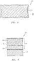
FIG. 6 is a sectional block diagram of a coated component. -
FIG. 7 is a sectional block diagram of a portion of another coated component. -
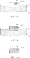
FIG. 8 is a block diagram of a masked component prior to being coating. -
FIG. 9 is a block diagram of the masked component during the coating. -
FIG. 10 is a block diagram of the component after the coating and unmasked. -
FIG. 11 is a side cutaway illustration of a gas turbine engine. -
FIG. 1 is a block diagram illustration of asystem 20 for coating acomponent 22.FIG. 2 is a flow diagram of amethod 200 for coating a component (e.g., 22) using a system such as, for example, thesystem 20 ofFIG. 1 . - The
component 22 may be configured for an item of rotational equipment such as a gas turbine engine. This gas turbine engine may be configured in an aircraft propulsion system. Alternatively, the gas turbine engine may be configured in an auxiliary power unit for the aircraft. The methods and apparatuses of the present disclosure, however, are not limited to such aircraft applications. In other embodiments, for example, the gas turbine engine may be configured as an industrial gas turbine engine in a power generation system. In still other embodiments, the item of rotational equipment may alternatively be configured as a wind turbine, a water turbine or any other item of rotational equipment which includes a component with a coating as described below. - For ease of description, the
component 22 is described below as a component of a gas turbine engine. Thecomponent 22, for example, may be configured as or include an airfoil as described below. Examples of such a component include, but are not limited to, a fan blade, a compressor blade, a turbine blade, a guide vane, a compressor vane, a turbine vane and a propeller. Thecomponent 22 of the present disclosure, however, is not limited to the foregoing exemplary component configurations, or to rotational equipment applications. - The
component 22 has ametal component body 24; e.g., base material. Thiscomponent body 24 provides thecomponent 22 with its structure and general geometry; e.g., shape and dimensions. Thecomponent body 24 is constructed from metal, which is the base material. Examples of suitable metals include, but are not limited to, nickel (Ni), titanium (Ti) or an alloy of one or more of the foregoing materials. Examples of a component body metal alloy include, but are not limited to, airfoil and various hot section turbine components. Thecomponent body 24 of the present disclosure, however, is not limited to the foregoing exemplary component body materials. - In
step 202,source material 26 is provided for coating thecomponent 22 and, more particularly, itsbody 24. Thesource material 26, for example, may be disposed in anopen container 27 to provide a bed of thesource material 26 as shown inFIG. 1 . Thissource material 26 includes metal alloy gravel. Thesource material 26 may also include activator material, which may be homogeneously or heterogeneously mixed with some or all of the metal alloy gravel. - The metal alloy gravel includes a loose aggregation of small particles of metal alloy material. This metal alloy gravel is different from a quantity of metal alloy dust or powder. The metal alloy gravel of the present disclosure, in particular, has an average particle size of at least about 0.125 inches (3.18 mm). The particles of the metal alloy gravel, for example, may have an average particle size between about 0.100 inches and about 0.500 inches (2.54 mm and 12.7 mm); however, the present disclosure is not limited to the foregoing exemplary range.
- The particle size may be a measure of a particle's diameter where that particle is generally spherical. The particle size may alternatively be a measure of a particle's length, width or height where that particle is non-spherical; e.g., globular cluster, cubic, ellipsoidal, etc. In such a case, the average particle size of that particle may be the average of the particle's length, width and height. In turn, the average particle size of the metal alloy gravel may be calculated as an average of the particle sizes of the particles in the metal alloy gravel.
- The metal alloy material is a metal alloy which includes aluminum. The metal alloy material, for example, may be an alloy of cobalt (Co) and aluminum such as, for example, CoAl. In another example, the metal alloy material may be an alloy of chrome (Cr) and aluminum such as, for example, CrAl. The present disclosure, however, is not limited to the foregoing exemplary alloys.
- The activator material is selected to promote diffusion of the aluminum from the metal alloy gravel into the
component 22 and itsbody 24 to form an aluminide coating 28 (seeFIG. 6 ). An example of such an activation material is a halide material; e.g., chloride halide. The present disclosure, however, is not limited to the foregoing exemplary halide or activator material. - In
step 204, thecomponent 22 is disposed with thesource material 26. Thecomponent 22, for example, may be partially submersed (e.g., covered) within the bed of thesource material 26 as shown inFIGS. 1 and3 . In this manner, thecomponent 22 projects into the bed of thesource material 26 such as that the source material 26 contacts multiple exterior surfaces 30-32 of thecomponent body 24. Alternatively, thecomponent 22 may be laid on top of the bed of thesource material 26 as shown inFIG. 4 . In this manner, only thebottom surface 30 of thecomponent body 24 contacts thesource material 26. Still alternatively, thecomponent 22 may be completely submersed within (e.g., covered and surrounded by) thesource material 26 as shown inFIG. 5 . In this manner, the source material 26 contacts all exterior surfaces (e.g., 30-33) of thecomponent body 24 ofFIG. 5 . - In
step 206, thealuminide coating 28 is formed on the component 22 (seeFIG. 6 ). In particular, an environment within a heating vessel 34 (e.g., oven) and, as a result, at least an outer peripheral portion of thecomponent 22 as well as thesource material 26 is heated to an elevated temperature using a heater 36 (seeFIG. 1 ). At this elevated temperature, the aluminum from the metal alloy gravel diffuses into material in an outer peripheral region of thecomponent body 24 and thereby forms the aluminide coating 28 (seeFIG. 6 ). - The elevated temperature may be selected such that the
aluminide coating 28 is generally (or more of) an inward diffusion coating rather than an outward diffusion coating. The term "inward diffusion coating" may describe a coating formed by diffusing material into a base material; i.e., the material being coated. Generally speaking, such an inward diffusion coating does not substantially change the exterior dimensions of the original base material. In contrast, the term "outward diffusion coating" may describe a coating formed by the diffusion of a base material outward into surrounding material; i.e., coating material. Generally speaking, such an outward diffusion coating increases the exterior dimensions of the original base material. - To form an inward diffusion coating, the elevated temperature is selected to be between about eleven-hundred degrees Fahrenheit (1100°F or 593°C) and about two-thousand degrees Fahrenheit (2000°F or 1093°C). In some embodiments, for example, the elevated temperature maybe between about fourteen-hundred degrees Fahrenheit (1400°F or 760°C) and about sixteen-hundred degrees Fahrenheit (1600°F or 871°C). In some embodiments, the elevated temperature may be between about sixteen-hundred degrees Fahrenheit (1600°F or 871°C) and about seventeen-hundred degrees Fahrenheit (1700°F or 927°C). In some embodiments, the elevated temperature may be between about seventeen-hundred degrees Fahrenheit (1700°F or 927°C) and about nineteen-hundred degrees Fahrenheit (1900°F or 1038°C).
- Upon completion of the
coating step 206, an exterior of thecomponent body 24 ofFIG. 6 is completely (partially inFIG. 10 ) coated with thealuminide coating 28; e.g., an inward diffusion aluminide coating. Thisaluminide coating 28 may be referred to as a green state coating. Herein, the term "green state coating" may describe a coating with a relatively high weight percentage and a relatively high atomic percentage of aluminum. Thealuminide coating 28, for example, may have a weight percentage of aluminum of about forty percent (40%) to about sixty percent (60%). Thealuminide coating 28 may have an atomic percentage of aluminum of about sixty percent (60%) to about seventy percent (70%). Such a green state coating may be relatively brittle. Thealuminide coating 28 formed in thecoating step 206, however, is not limited to the foregoing exemplary weight and atomic percentages of aluminum. - In
step 208, thecoated component 22 and, more particularly, thealuminide coating 28 is heat treated to provide a heat treated aluminide coating 28' (seeFIG. 7 ). In particular, the environment within theheating vessel 34 ofFIG. 1 (or another heating vessel or system) and, as a result, thealuminide coating 28 is heated to another elevated temperature. At this elevated temperature, the relatively brittle green state coating may be transformed into a less brittle diffused state coating. Herein, the term "diffused state coating" may describe a coating with a relatively low weight percentage and a relatively low atomic percentage of aluminum. The heat treated aluminide coating 28', for example, may have a weight percentage of aluminum of about twenty-five percent (25%) to about thirty-two percent (32%). The heat treated aluminide coating 28' may have an atomic percentage of aluminum of about forty percent (40%) to about fifty percent (50%). The heat treated aluminide coating 28' formed in theheat treating step 208, however, is not limited to the foregoing exemplary weight and atomic percentages of aluminum. - The heat treated aluminide coating 28' may be a three-zone aluminide coating as shown in
FIG. 7 . Such a three-zone aluminide coating may include adiffusion zone 38, anintermediate zone 40 and anadditive zone 42. Thediffusion zone 38 is between the base material of thecomponent body 24 and theintermediate zone 40. Thiszone 38 includes a relatively low atomic percentage of aluminum which has diffused into the base material of thecomponent body 24. Theintermediate zone 40 is between thediffusion zone 38 and theadditive zone 42. Thiszone 40 includes a higher atomic percentage of aluminum than thediffusion zone 38, which aluminum is also diffused to a lesser degree into the base material of thecomponent body 24. Theadditive zone 42 is the outermost zone and includes the highest atomic percentage of aluminum, where the base material of thecomponent body 24 may have diffused outward to form an additive portion. - To form the heat treated aluminide coating 28', the elevated temperature is selected to be between about 1700°F and about 2100°F (927°C and 1149°C. In some embodiments, for example, the elevated temperature may be between about 1800°F and about 2000°F (982°C and 1093°C).
- In some embodiments, one or more portions of the
component body 24 may be masked to prevent coating those portions with thealuminide coating 28, 28' described above. For example, referring toFIG. 8 , a mask 44 (e.g., masking putty) may be applied to an exterior surface of thecomponent body 24. The masked offcomponent 22 may then undergo thecoating step 206 as shown inFIG. 9 . After thiscoating step 206, themask 44 may be removed from the now coatedcomponent body 24 to reveal an uncoated (e.g., bare)surface 46 of thecomponent body 24 as shown inFIG. 10 where the mask was removed. - As described above, the
component 22 of the present disclosure may be configured with various different types and configurations of rotational equipment, or other devices.FIG. 11 illustrates one such type and configuration of the rotational equipment - a geared turbofangas turbine engine 70. Thisturbine engine 70 includes various types and configurations of rotor blade airfoils as described below as well as stator vane airfoils, where thecomponent 22 can be configured as anyone of the foregoing airfoils, or other structures not mentioned herein. - Referring still to
FIG. 11 , theturbine engine 70 extends along anaxial centerline 76 between anupstream airflow inlet 78 and adownstream airflow exhaust 80. Theturbine engine 70 includes afan section 82, acompressor section 83, acombustor section 84 and aturbine section 85. Thecompressor section 83 includes a low pressure compressor (LPC)section 83A and a high pressure compressor (HPC)section 83B. Theturbine section 85 includes a high pressure turbine (HPT)section 85A and a low pressure turbine (LPT)section 85B. - The engine sections 82-85 are arranged sequentially along the
centerline 76 within anengine housing 86. Thishousing 86 includes an inner case 88 (e.g., a core case) and an outer case 90 (e.g., a fan case). Theinner case 88 may house one or more of the engine sections 83-85; e.g., an engine core. Theouter case 90 may house at least thefan section 82. - Each of the
engine sections - The
fan rotor 92 is connected to agear train 98, for example, through afan shaft 100. Thegear train 98 and theLPC rotor 93 are connected to and driven by theLPT rotor 96 through alow speed shaft 101. TheHPC rotor 94 is connected to and driven by theHPT rotor 95 through ahigh speed shaft 102. The shafts 100-102 are rotatably supported by a plurality ofbearings 104. Each of thesebearings 104 is connected to theengine housing 86 by at least one stationary structure such as, for example, an annular support strut. - During operation, air enters the
turbine engine 70 through theairflow inlet 78. This air is directed through thefan section 82 and into acore gas path 106 and abypass gas path 108. Thecore gas path 106 flows sequentially through the engine sections 83-85. Thebypass gas path 108 flows away from thefan section 82 through a bypass duct, which circumscribes and bypasses the engine core. The air within thecore gas path 106 may be referred to as "core air". The air within thebypass gas path 108 may be referred to as "bypass air". - The core air is compressed by the
compressor rotors combustion chamber 110 of a combustor in thecombustor section 84. Fuel is injected into thecombustion chamber 110 and mixed with the compressed core air to provide a fuel-air mixture. This fuel air mixture is ignited and combustion products thereof flow through and sequentially cause theturbine rotors turbine rotors compressor rotors turbine rotor 96 also drives rotation of thefan rotor 92, which propels bypass air through and out of thebypass gas path 108. The propulsion of the bypass air may account for a majority of thrust generated by theturbine engine 70, e.g., more than seventy-five percent (75%) of engine thrust. Theturbine engine 70 of the present disclosure, however, is not limited to the foregoing exemplary thrust ratio. - The
component 22 may be included in various aircraft and industrial turbine engines other than the one described above as well as in other types of rotational equipment and non-rotating equipment. Thecomponent 22 may be included in a geared turbine engine where a gear train connects one or more shafts to one or more rotors in a fan section, a compressor section and/or any other engine section. Alternatively, thecomponent 22 may be included in a turbine engine configured without a gear train. Thecomponent 22 may be included in a geared or non-geared turbine engine configured with a single spool, with two spools (e.g., seeFIG. 11 ), or with more than two spools. The turbine engine may be configured as a turbofan engine, a turbojet engine, a propfan engine, a pusher fan engine or any other type of turbine engine. The present invention, however, is not limited to any particular types or configurations of turbine engines or rotational equipment. - While various embodiments of the present invention have been disclosed, it will be apparent to those of ordinary skill in the art that many more embodiments and implementations are possible within the scope of the invention. For example, the present invention as described herein includes several aspects and embodiments that include particular features. Although these features may be described individually, it is within the scope of the present invention that some or all of these features may be combined with any one of the aspects and remain within the scope of the invention. Accordingly, the present invention is not to be restricted except in light of the attached claims and their equivalents.
Claims (15)
- A method for coating a component (22), comprising:disposing the component (22) with metal alloy gravel comprising aluminum; andforming an aluminide coating (28) on the component (22), wherein the aluminum from the metal alloy gravel diffuses into the component (22) to form the aluminide coating (28).
- The method of claim 1, wherein the metal alloy gravel has an average particle size of at least about 0.125 inches (3.18 mm).
- The method of claim 1 or 2, wherein the metal alloy gravel further comprises chrome aluminum and/or cobalt aluminum.
- The method of any preceding claim, further comprising heating the metal alloy gravel adjacent the component (22) to a temperature between 1200 degrees Fahrenheit and 1750 degrees Fahrenheit (649 degrees Celsius and 954 degrees Celsius), optionally 1550 degrees Fahrenheit and 1750 degrees Fahrenheit (843 degrees Celsius and 954 degrees Celsius)
- The method of any preceding claim, wherein activator material is disposed with the metal alloy gravel.
- The method of claim 5, where the activator material comprises halide material.
- The method of any preceding claim, further comprising heat treating the aluminide coating (28) to provide a heat treated diffusion coating, wherein optionally the heat treating comprises heating the aluminide coating (28) to a temperature between 1700 degrees Fahrenheit and 2100 degrees Fahrenheit (927 degrees Celsius and 1149 degrees Celsius).
- The method of claim 7, wherein the aluminide coating (28) is a green state coating, and the heat treated diffusion coating is a three-zone aluminide coating.
- The method of any preceding claim, wherein the component (22) is laid on top of the metal alloy gravel.
- The method of any preceding claim, wherein the component (22) is partially or completely submersed in the metal alloy gravel.
- The method of any preceding claim, further comprising masking a portion of the component (22) such that the masked portion of the component (22) is not coated with the aluminide coating (28).
- The method of any preceding claim, wherein the component (22) comprises a nickel alloy.
- The method of any preceding claim, wherein the component (22) is configured as a part of a gas turbine engine (70), and optionally the component (22) is an airfoil.
- A method for coating a component (22) of a gas turbine engine (70), comprising:providing a bed of material, the bed of material comprising metal alloy material and activator material, and the metal alloy material comprising cobalt and aluminum, wherein the metal alloy material has an average particle size of at least about 0.125 inches (3.18 mm);disposing the component (22) with the bed of material;heating the bed of material and the component (22) to form an aluminide coating on the component, wherein the component is heated to a temperature between 1200 degrees Fahrenheit and 1750 degrees Fahrenheit (649 degrees Celsius and 954 degrees Celsius), and wherein the aluminum from the metal alloy material diffuses into the component (22) to form the aluminide coating (28).
- A method for coating a component (22) of a gas turbine engine, comprising:providing a bed of material, the bed of material comprising metal alloy material and activator material, and the metal alloy material comprising chrome and aluminum, wherein the metal alloy material has an average particle size of at least about 0.125 inches (3.18 mm);disposing the component (22) with the bed of material;heating the bed of material and the component (22) to form an aluminide coating (28) on the component, wherein the component (22) is heated to a temperature between 1200 degrees Fahrenheit and 1750 degrees Fahrenheit (649 degrees Celsius and 954 degrees Celsius), and wherein the aluminum from the metal alloy material diffuses into the component to form the aluminide coating (28).
Applications Claiming Priority (1)
| Application Number | Priority Date | Filing Date | Title |
|---|---|---|---|
| US15/016,344 US20170226623A1 (en) | 2016-02-05 | 2016-02-05 | Forming aluminide coating using metal alloy gravel |
Publications (2)
| Publication Number | Publication Date |
|---|---|
| EP3202946A1 true EP3202946A1 (en) | 2017-08-09 |
| EP3202946B1 EP3202946B1 (en) | 2020-10-21 |
Family
ID=57909510
Family Applications (1)
| Application Number | Title | Priority Date | Filing Date |
|---|---|---|---|
| EP17153434.0A Active EP3202946B1 (en) | 2016-02-05 | 2017-01-27 | Forming aluminide coating using metal alloy gravel |
Country Status (2)
| Country | Link |
|---|---|
| US (1) | US20170226623A1 (en) |
| EP (1) | EP3202946B1 (en) |
Citations (4)
| Publication number | Priority date | Publication date | Assignee | Title |
|---|---|---|---|---|
| EP0731187A1 (en) * | 1995-03-07 | 1996-09-11 | Turbine Components Corporation | Method of forming a protective diffusion layer on nickel, cobalt and iron based alloys |
| US6224941B1 (en) * | 1998-12-22 | 2001-05-01 | General Electric Company | Pulsed-vapor phase aluminide process for high temperature oxidation-resistant coating applications |
| US20070122647A1 (en) * | 2005-11-28 | 2007-05-31 | Russo Vincent J | Duplex gas phase coating |
| US20120213928A1 (en) * | 2009-05-18 | 2012-08-23 | Wang Yongqing | Forming reactive element modified aluminide coatings with low reactive element content using vapor phase techniques |
Family Cites Families (3)
| Publication number | Priority date | Publication date | Assignee | Title |
|---|---|---|---|---|
| US3837901A (en) * | 1970-08-21 | 1974-09-24 | Gen Electric | Diffusion-coating of nickel-base superalloy articles |
| US20090035485A1 (en) * | 2007-08-02 | 2009-02-05 | United Technologies Corporation | Method for forming active-element aluminide diffusion coatings |
| US8318251B2 (en) * | 2009-09-30 | 2012-11-27 | General Electric Company | Method for coating honeycomb seal using a slurry containing aluminum |
-
2016
- 2016-02-05 US US15/016,344 patent/US20170226623A1/en not_active Abandoned
-
2017
- 2017-01-27 EP EP17153434.0A patent/EP3202946B1/en active Active
Patent Citations (4)
| Publication number | Priority date | Publication date | Assignee | Title |
|---|---|---|---|---|
| EP0731187A1 (en) * | 1995-03-07 | 1996-09-11 | Turbine Components Corporation | Method of forming a protective diffusion layer on nickel, cobalt and iron based alloys |
| US6224941B1 (en) * | 1998-12-22 | 2001-05-01 | General Electric Company | Pulsed-vapor phase aluminide process for high temperature oxidation-resistant coating applications |
| US20070122647A1 (en) * | 2005-11-28 | 2007-05-31 | Russo Vincent J | Duplex gas phase coating |
| US20120213928A1 (en) * | 2009-05-18 | 2012-08-23 | Wang Yongqing | Forming reactive element modified aluminide coatings with low reactive element content using vapor phase techniques |
Also Published As
| Publication number | Publication date |
|---|---|
| EP3202946B1 (en) | 2020-10-21 |
| US20170226623A1 (en) | 2017-08-10 |
Similar Documents
| Publication | Publication Date | Title |
|---|---|---|
| EP3734160B1 (en) | Monolithic body including an internal passage with a generally teardrop shaped cross-sectional geometry | |
| EP3196322A1 (en) | Thin seal for a gas turbine engine | |
| JP2017141830A (en) | Riblets for flowpath surface of turbomachine | |
| US10006367B2 (en) | Self-opening cooling passages for a gas turbine engine | |
| EP3205829A1 (en) | Flowpath contouring | |
| CN116220824A (en) | Turbine engine airfoil with modified leading edge | |
| US12320271B2 (en) | Slurry based diffusion coatings for blade under platform of internally-cooled components and process therefor | |
| CN105909317A (en) | Engine component | |
| EP3577321B1 (en) | Coated flange bolt hole and methods of forming the same | |
| US20160153286A1 (en) | Turbine clearance control utilizing low alpha material | |
| CN107091124B (en) | System and method for simultaneously depositing multiple coatings on a turbine blade | |
| US11701754B2 (en) | Article and method of manufacturing the same | |
| EP3202946B1 (en) | Forming aluminide coating using metal alloy gravel | |
| US20150369047A1 (en) | Rotor and gas turbine engine including same | |
| EP3012343A1 (en) | Coating system for internally-cooled component and process therefor | |
| EP2876185A1 (en) | Coated article and method of applying a coating to an article | |
| US12018840B2 (en) | Combustor arrangement | |
| EP3862534B1 (en) | Blade with wearable tip-rub-portions above squealer pocket | |
| EP3231989A2 (en) | System and method for rejuvenating coated components of gas turbine engines | |
| EP3090075B1 (en) | Hot corrosion-protected article and manufacture method therefor |
Legal Events
| Date | Code | Title | Description |
|---|---|---|---|
| PUAI | Public reference made under article 153(3) epc to a published international application that has entered the european phase |
Free format text: ORIGINAL CODE: 0009012 |
|
| STAA | Information on the status of an ep patent application or granted ep patent |
Free format text: STATUS: THE APPLICATION HAS BEEN PUBLISHED |
|
| AK | Designated contracting states |
Kind code of ref document: A1 Designated state(s): AL AT BE BG CH CY CZ DE DK EE ES FI FR GB GR HR HU IE IS IT LI LT LU LV MC MK MT NL NO PL PT RO RS SE SI SK SM TR |
|
| AX | Request for extension of the european patent |
Extension state: BA ME |
|
| STAA | Information on the status of an ep patent application or granted ep patent |
Free format text: STATUS: REQUEST FOR EXAMINATION WAS MADE |
|
| 17P | Request for examination filed |
Effective date: 20180209 |
|
| RBV | Designated contracting states (corrected) |
Designated state(s): AL AT BE BG CH CY CZ DE DK EE ES FI FR GB GR HR HU IE IS IT LI LT LU LV MC MK MT NL NO PL PT RO RS SE SI SK SM TR |
|
| STAA | Information on the status of an ep patent application or granted ep patent |
Free format text: STATUS: EXAMINATION IS IN PROGRESS |
|
| 17Q | First examination report despatched |
Effective date: 20190204 |
|
| GRAP | Despatch of communication of intention to grant a patent |
Free format text: ORIGINAL CODE: EPIDOSNIGR1 |
|
| RIC1 | Information provided on ipc code assigned before grant |
Ipc: C23C 10/48 20060101ALI20200331BHEP Ipc: C23C 10/52 20060101ALI20200331BHEP Ipc: C23C 10/56 20060101ALI20200331BHEP Ipc: C23C 10/04 20060101AFI20200331BHEP Ipc: C23C 24/08 20060101ALI20200331BHEP Ipc: C22F 1/04 20060101ALI20200331BHEP |
|
| STAA | Information on the status of an ep patent application or granted ep patent |
Free format text: STATUS: GRANT OF PATENT IS INTENDED |
|
| INTG | Intention to grant announced |
Effective date: 20200507 |
|
| GRAS | Grant fee paid |
Free format text: ORIGINAL CODE: EPIDOSNIGR3 |
|
| GRAA | (expected) grant |
Free format text: ORIGINAL CODE: 0009210 |
|
| STAA | Information on the status of an ep patent application or granted ep patent |
Free format text: STATUS: THE PATENT HAS BEEN GRANTED |
|
| AK | Designated contracting states |
Kind code of ref document: B1 Designated state(s): AL AT BE BG CH CY CZ DE DK EE ES FI FR GB GR HR HU IE IS IT LI LT LU LV MC MK MT NL NO PL PT RO RS SE SI SK SM TR |
|
| REG | Reference to a national code |
Ref country code: GB Ref legal event code: FG4D |
|
| REG | Reference to a national code |
Ref country code: CH Ref legal event code: EP |
|
| REG | Reference to a national code |
Ref country code: IE Ref legal event code: FG4D |
|
| REG | Reference to a national code |
Ref country code: AT Ref legal event code: REF Ref document number: 1325952 Country of ref document: AT Kind code of ref document: T Effective date: 20201115 |
|
| REG | Reference to a national code |
Ref country code: DE Ref legal event code: R096 Ref document number: 602017025697 Country of ref document: DE |
|
| REG | Reference to a national code |
Ref country code: AT Ref legal event code: MK05 Ref document number: 1325952 Country of ref document: AT Kind code of ref document: T Effective date: 20201021 |
|
| RAP2 | Party data changed (patent owner data changed or rights of a patent transferred) |
Owner name: RAYTHEON TECHNOLOGIES CORPORATION |
|
| REG | Reference to a national code |
Ref country code: NL Ref legal event code: MP Effective date: 20201021 |
|
| PG25 | Lapsed in a contracting state [announced via postgrant information from national office to epo] |
Ref country code: NO Free format text: LAPSE BECAUSE OF FAILURE TO SUBMIT A TRANSLATION OF THE DESCRIPTION OR TO PAY THE FEE WITHIN THE PRESCRIBED TIME-LIMIT Effective date: 20210121 Ref country code: NL Free format text: LAPSE BECAUSE OF FAILURE TO SUBMIT A TRANSLATION OF THE DESCRIPTION OR TO PAY THE FEE WITHIN THE PRESCRIBED TIME-LIMIT Effective date: 20201021 Ref country code: PT Free format text: LAPSE BECAUSE OF FAILURE TO SUBMIT A TRANSLATION OF THE DESCRIPTION OR TO PAY THE FEE WITHIN THE PRESCRIBED TIME-LIMIT Effective date: 20210222 Ref country code: RS Free format text: LAPSE BECAUSE OF FAILURE TO SUBMIT A TRANSLATION OF THE DESCRIPTION OR TO PAY THE FEE WITHIN THE PRESCRIBED TIME-LIMIT Effective date: 20201021 Ref country code: GR Free format text: LAPSE BECAUSE OF FAILURE TO SUBMIT A TRANSLATION OF THE DESCRIPTION OR TO PAY THE FEE WITHIN THE PRESCRIBED TIME-LIMIT Effective date: 20210122 Ref country code: FI Free format text: LAPSE BECAUSE OF FAILURE TO SUBMIT A TRANSLATION OF THE DESCRIPTION OR TO PAY THE FEE WITHIN THE PRESCRIBED TIME-LIMIT Effective date: 20201021 |
|
| REG | Reference to a national code |
Ref country code: LT Ref legal event code: MG4D |
|
| PG25 | Lapsed in a contracting state [announced via postgrant information from national office to epo] |
Ref country code: AT Free format text: LAPSE BECAUSE OF FAILURE TO SUBMIT A TRANSLATION OF THE DESCRIPTION OR TO PAY THE FEE WITHIN THE PRESCRIBED TIME-LIMIT Effective date: 20201021 Ref country code: ES Free format text: LAPSE BECAUSE OF FAILURE TO SUBMIT A TRANSLATION OF THE DESCRIPTION OR TO PAY THE FEE WITHIN THE PRESCRIBED TIME-LIMIT Effective date: 20201021 Ref country code: BG Free format text: LAPSE BECAUSE OF FAILURE TO SUBMIT A TRANSLATION OF THE DESCRIPTION OR TO PAY THE FEE WITHIN THE PRESCRIBED TIME-LIMIT Effective date: 20210121 Ref country code: IS Free format text: LAPSE BECAUSE OF FAILURE TO SUBMIT A TRANSLATION OF THE DESCRIPTION OR TO PAY THE FEE WITHIN THE PRESCRIBED TIME-LIMIT Effective date: 20210221 Ref country code: PL Free format text: LAPSE BECAUSE OF FAILURE TO SUBMIT A TRANSLATION OF THE DESCRIPTION OR TO PAY THE FEE WITHIN THE PRESCRIBED TIME-LIMIT Effective date: 20201021 Ref country code: LV Free format text: LAPSE BECAUSE OF FAILURE TO SUBMIT A TRANSLATION OF THE DESCRIPTION OR TO PAY THE FEE WITHIN THE PRESCRIBED TIME-LIMIT Effective date: 20201021 Ref country code: SE Free format text: LAPSE BECAUSE OF FAILURE TO SUBMIT A TRANSLATION OF THE DESCRIPTION OR TO PAY THE FEE WITHIN THE PRESCRIBED TIME-LIMIT Effective date: 20201021 |
|
| PG25 | Lapsed in a contracting state [announced via postgrant information from national office to epo] |
Ref country code: HR Free format text: LAPSE BECAUSE OF FAILURE TO SUBMIT A TRANSLATION OF THE DESCRIPTION OR TO PAY THE FEE WITHIN THE PRESCRIBED TIME-LIMIT Effective date: 20201021 |
|
| REG | Reference to a national code |
Ref country code: DE Ref legal event code: R097 Ref document number: 602017025697 Country of ref document: DE |
|
| PG25 | Lapsed in a contracting state [announced via postgrant information from national office to epo] |
Ref country code: RO Free format text: LAPSE BECAUSE OF FAILURE TO SUBMIT A TRANSLATION OF THE DESCRIPTION OR TO PAY THE FEE WITHIN THE PRESCRIBED TIME-LIMIT Effective date: 20201021 Ref country code: SK Free format text: LAPSE BECAUSE OF FAILURE TO SUBMIT A TRANSLATION OF THE DESCRIPTION OR TO PAY THE FEE WITHIN THE PRESCRIBED TIME-LIMIT Effective date: 20201021 Ref country code: CZ Free format text: LAPSE BECAUSE OF FAILURE TO SUBMIT A TRANSLATION OF THE DESCRIPTION OR TO PAY THE FEE WITHIN THE PRESCRIBED TIME-LIMIT Effective date: 20201021 Ref country code: EE Free format text: LAPSE BECAUSE OF FAILURE TO SUBMIT A TRANSLATION OF THE DESCRIPTION OR TO PAY THE FEE WITHIN THE PRESCRIBED TIME-LIMIT Effective date: 20201021 Ref country code: SM Free format text: LAPSE BECAUSE OF FAILURE TO SUBMIT A TRANSLATION OF THE DESCRIPTION OR TO PAY THE FEE WITHIN THE PRESCRIBED TIME-LIMIT Effective date: 20201021 Ref country code: LT Free format text: LAPSE BECAUSE OF FAILURE TO SUBMIT A TRANSLATION OF THE DESCRIPTION OR TO PAY THE FEE WITHIN THE PRESCRIBED TIME-LIMIT Effective date: 20201021 |
|
| PLBE | No opposition filed within time limit |
Free format text: ORIGINAL CODE: 0009261 |
|
| STAA | Information on the status of an ep patent application or granted ep patent |
Free format text: STATUS: NO OPPOSITION FILED WITHIN TIME LIMIT |
|
| PG25 | Lapsed in a contracting state [announced via postgrant information from national office to epo] |
Ref country code: MC Free format text: LAPSE BECAUSE OF FAILURE TO SUBMIT A TRANSLATION OF THE DESCRIPTION OR TO PAY THE FEE WITHIN THE PRESCRIBED TIME-LIMIT Effective date: 20201021 Ref country code: DK Free format text: LAPSE BECAUSE OF FAILURE TO SUBMIT A TRANSLATION OF THE DESCRIPTION OR TO PAY THE FEE WITHIN THE PRESCRIBED TIME-LIMIT Effective date: 20201021 |
|
| REG | Reference to a national code |
Ref country code: CH Ref legal event code: PL |
|
| 26N | No opposition filed |
Effective date: 20210722 |
|
| PG25 | Lapsed in a contracting state [announced via postgrant information from national office to epo] |
Ref country code: LU Free format text: LAPSE BECAUSE OF NON-PAYMENT OF DUE FEES Effective date: 20210127 |
|
| REG | Reference to a national code |
Ref country code: BE Ref legal event code: MM Effective date: 20210131 |
|
| PG25 | Lapsed in a contracting state [announced via postgrant information from national office to epo] |
Ref country code: IT Free format text: LAPSE BECAUSE OF FAILURE TO SUBMIT A TRANSLATION OF THE DESCRIPTION OR TO PAY THE FEE WITHIN THE PRESCRIBED TIME-LIMIT Effective date: 20201021 Ref country code: AL Free format text: LAPSE BECAUSE OF FAILURE TO SUBMIT A TRANSLATION OF THE DESCRIPTION OR TO PAY THE FEE WITHIN THE PRESCRIBED TIME-LIMIT Effective date: 20201021 |
|
| PG25 | Lapsed in a contracting state [announced via postgrant information from national office to epo] |
Ref country code: LI Free format text: LAPSE BECAUSE OF NON-PAYMENT OF DUE FEES Effective date: 20210131 Ref country code: SI Free format text: LAPSE BECAUSE OF FAILURE TO SUBMIT A TRANSLATION OF THE DESCRIPTION OR TO PAY THE FEE WITHIN THE PRESCRIBED TIME-LIMIT Effective date: 20201021 Ref country code: CH Free format text: LAPSE BECAUSE OF NON-PAYMENT OF DUE FEES Effective date: 20210131 |
|
| PG25 | Lapsed in a contracting state [announced via postgrant information from national office to epo] |
Ref country code: IE Free format text: LAPSE BECAUSE OF NON-PAYMENT OF DUE FEES Effective date: 20210127 |
|
| PG25 | Lapsed in a contracting state [announced via postgrant information from national office to epo] |
Ref country code: IS Free format text: LAPSE BECAUSE OF FAILURE TO SUBMIT A TRANSLATION OF THE DESCRIPTION OR TO PAY THE FEE WITHIN THE PRESCRIBED TIME-LIMIT Effective date: 20210221 |
|
| PG25 | Lapsed in a contracting state [announced via postgrant information from national office to epo] |
Ref country code: BE Free format text: LAPSE BECAUSE OF NON-PAYMENT OF DUE FEES Effective date: 20210131 |
|
| PG25 | Lapsed in a contracting state [announced via postgrant information from national office to epo] |
Ref country code: HU Free format text: LAPSE BECAUSE OF FAILURE TO SUBMIT A TRANSLATION OF THE DESCRIPTION OR TO PAY THE FEE WITHIN THE PRESCRIBED TIME-LIMIT; INVALID AB INITIO Effective date: 20170127 |
|
| P01 | Opt-out of the competence of the unified patent court (upc) registered |
Effective date: 20230520 |
|
| PG25 | Lapsed in a contracting state [announced via postgrant information from national office to epo] |
Ref country code: CY Free format text: LAPSE BECAUSE OF FAILURE TO SUBMIT A TRANSLATION OF THE DESCRIPTION OR TO PAY THE FEE WITHIN THE PRESCRIBED TIME-LIMIT Effective date: 20201021 |
|
| PG25 | Lapsed in a contracting state [announced via postgrant information from national office to epo] |
Ref country code: MK Free format text: LAPSE BECAUSE OF FAILURE TO SUBMIT A TRANSLATION OF THE DESCRIPTION OR TO PAY THE FEE WITHIN THE PRESCRIBED TIME-LIMIT Effective date: 20201021 |
|
| PG25 | Lapsed in a contracting state [announced via postgrant information from national office to epo] |
Ref country code: MT Free format text: LAPSE BECAUSE OF FAILURE TO SUBMIT A TRANSLATION OF THE DESCRIPTION OR TO PAY THE FEE WITHIN THE PRESCRIBED TIME-LIMIT Effective date: 20201021 |
|
| REG | Reference to a national code |
Ref country code: DE Ref legal event code: R081 Ref document number: 602017025697 Country of ref document: DE Owner name: RTX CORPORATION (N.D.GES.D. STAATES DELAWARE),, US Free format text: FORMER OWNER: UNITED TECHNOLOGIES CORPORATION, FARMINGTON, CONN., US |
|
| PG25 | Lapsed in a contracting state [announced via postgrant information from national office to epo] |
Ref country code: TR Free format text: LAPSE BECAUSE OF FAILURE TO SUBMIT A TRANSLATION OF THE DESCRIPTION OR TO PAY THE FEE WITHIN THE PRESCRIBED TIME-LIMIT Effective date: 20201021 |
|
| PGFP | Annual fee paid to national office [announced via postgrant information from national office to epo] |
Ref country code: GB Payment date: 20251219 Year of fee payment: 10 |
|
| PGFP | Annual fee paid to national office [announced via postgrant information from national office to epo] |
Ref country code: FR Payment date: 20251218 Year of fee payment: 10 |
|
| PGFP | Annual fee paid to national office [announced via postgrant information from national office to epo] |
Ref country code: DE Payment date: 20251217 Year of fee payment: 10 |