EP3202872A1 - Organic light emitting element - Google Patents
Organic light emitting element Download PDFInfo
- Publication number
- EP3202872A1 EP3202872A1 EP14903217.9A EP14903217A EP3202872A1 EP 3202872 A1 EP3202872 A1 EP 3202872A1 EP 14903217 A EP14903217 A EP 14903217A EP 3202872 A1 EP3202872 A1 EP 3202872A1
- Authority
- EP
- European Patent Office
- Prior art keywords
- chemical formula
- group
- light emitting
- substituted
- emitting device
- Prior art date
- Legal status (The legal status is an assumption and is not a legal conclusion. Google has not performed a legal analysis and makes no representation as to the accuracy of the status listed.)
- Granted
Links
Images

Classifications
-
- H—ELECTRICITY
- H10—SEMICONDUCTOR DEVICES; ELECTRIC SOLID-STATE DEVICES NOT OTHERWISE PROVIDED FOR
- H10K—ORGANIC ELECTRIC SOLID-STATE DEVICES
- H10K50/00—Organic light-emitting devices
-
- H—ELECTRICITY
- H10—SEMICONDUCTOR DEVICES; ELECTRIC SOLID-STATE DEVICES NOT OTHERWISE PROVIDED FOR
- H10K—ORGANIC ELECTRIC SOLID-STATE DEVICES
- H10K85/00—Organic materials used in the body or electrodes of devices covered by this subclass
- H10K85/60—Organic compounds having low molecular weight
- H10K85/631—Amine compounds having at least two aryl rest on at least one amine-nitrogen atom, e.g. triphenylamine
-
- H—ELECTRICITY
- H10—SEMICONDUCTOR DEVICES; ELECTRIC SOLID-STATE DEVICES NOT OTHERWISE PROVIDED FOR
- H10K—ORGANIC ELECTRIC SOLID-STATE DEVICES
- H10K85/00—Organic materials used in the body or electrodes of devices covered by this subclass
- H10K85/60—Organic compounds having low molecular weight
-
- C—CHEMISTRY; METALLURGY
- C07—ORGANIC CHEMISTRY
- C07D—HETEROCYCLIC COMPOUNDS
- C07D209/00—Heterocyclic compounds containing five-membered rings, condensed with other rings, with one nitrogen atom as the only ring hetero atom
- C07D209/56—Ring systems containing three or more rings
- C07D209/80—[b, c]- or [b, d]-condensed
- C07D209/82—Carbazoles; Hydrogenated carbazoles
-
- C—CHEMISTRY; METALLURGY
- C07—ORGANIC CHEMISTRY
- C07D—HETEROCYCLIC COMPOUNDS
- C07D403/00—Heterocyclic compounds containing two or more hetero rings, having nitrogen atoms as the only ring hetero atoms, not provided for by group C07D401/00
- C07D403/02—Heterocyclic compounds containing two or more hetero rings, having nitrogen atoms as the only ring hetero atoms, not provided for by group C07D401/00 containing two hetero rings
- C07D403/10—Heterocyclic compounds containing two or more hetero rings, having nitrogen atoms as the only ring hetero atoms, not provided for by group C07D401/00 containing two hetero rings linked by a carbon chain containing aromatic rings
-
- C—CHEMISTRY; METALLURGY
- C09—DYES; PAINTS; POLISHES; NATURAL RESINS; ADHESIVES; COMPOSITIONS NOT OTHERWISE PROVIDED FOR; APPLICATIONS OF MATERIALS NOT OTHERWISE PROVIDED FOR
- C09K—MATERIALS FOR MISCELLANEOUS APPLICATIONS, NOT PROVIDED FOR ELSEWHERE
- C09K11/00—Luminescent materials, e.g. electroluminescent or chemiluminescent
- C09K11/06—Luminescent materials, e.g. electroluminescent or chemiluminescent containing organic luminescent materials
-
- H—ELECTRICITY
- H10—SEMICONDUCTOR DEVICES; ELECTRIC SOLID-STATE DEVICES NOT OTHERWISE PROVIDED FOR
- H10K—ORGANIC ELECTRIC SOLID-STATE DEVICES
- H10K85/00—Organic materials used in the body or electrodes of devices covered by this subclass
- H10K85/60—Organic compounds having low molecular weight
- H10K85/631—Amine compounds having at least two aryl rest on at least one amine-nitrogen atom, e.g. triphenylamine
- H10K85/633—Amine compounds having at least two aryl rest on at least one amine-nitrogen atom, e.g. triphenylamine comprising polycyclic condensed aromatic hydrocarbons as substituents on the nitrogen atom
-
- H—ELECTRICITY
- H10—SEMICONDUCTOR DEVICES; ELECTRIC SOLID-STATE DEVICES NOT OTHERWISE PROVIDED FOR
- H10K—ORGANIC ELECTRIC SOLID-STATE DEVICES
- H10K85/00—Organic materials used in the body or electrodes of devices covered by this subclass
- H10K85/60—Organic compounds having low molecular weight
- H10K85/649—Aromatic compounds comprising a hetero atom
- H10K85/654—Aromatic compounds comprising a hetero atom comprising only nitrogen as heteroatom
-
- H—ELECTRICITY
- H10—SEMICONDUCTOR DEVICES; ELECTRIC SOLID-STATE DEVICES NOT OTHERWISE PROVIDED FOR
- H10K—ORGANIC ELECTRIC SOLID-STATE DEVICES
- H10K85/00—Organic materials used in the body or electrodes of devices covered by this subclass
- H10K85/60—Organic compounds having low molecular weight
- H10K85/649—Aromatic compounds comprising a hetero atom
- H10K85/657—Polycyclic condensed heteroaromatic hydrocarbons
- H10K85/6572—Polycyclic condensed heteroaromatic hydrocarbons comprising only nitrogen in the heteroaromatic polycondensed ring system, e.g. phenanthroline or carbazole
-
- H—ELECTRICITY
- H10—SEMICONDUCTOR DEVICES; ELECTRIC SOLID-STATE DEVICES NOT OTHERWISE PROVIDED FOR
- H10K—ORGANIC ELECTRIC SOLID-STATE DEVICES
- H10K50/00—Organic light-emitting devices
- H10K50/10—OLEDs or polymer light-emitting diodes [PLED]
- H10K50/14—Carrier transporting layers
- H10K50/16—Electron transporting layers
-
- H—ELECTRICITY
- H10—SEMICONDUCTOR DEVICES; ELECTRIC SOLID-STATE DEVICES NOT OTHERWISE PROVIDED FOR
- H10K—ORGANIC ELECTRIC SOLID-STATE DEVICES
- H10K50/00—Organic light-emitting devices
- H10K50/10—OLEDs or polymer light-emitting diodes [PLED]
- H10K50/17—Carrier injection layers
- H10K50/171—Electron injection layers
-
- H—ELECTRICITY
- H10—SEMICONDUCTOR DEVICES; ELECTRIC SOLID-STATE DEVICES NOT OTHERWISE PROVIDED FOR
- H10K—ORGANIC ELECTRIC SOLID-STATE DEVICES
- H10K50/00—Organic light-emitting devices
- H10K50/10—OLEDs or polymer light-emitting diodes [PLED]
- H10K50/18—Carrier blocking layers
-
- H—ELECTRICITY
- H10—SEMICONDUCTOR DEVICES; ELECTRIC SOLID-STATE DEVICES NOT OTHERWISE PROVIDED FOR
- H10K—ORGANIC ELECTRIC SOLID-STATE DEVICES
- H10K50/00—Organic light-emitting devices
- H10K50/10—OLEDs or polymer light-emitting diodes [PLED]
- H10K50/18—Carrier blocking layers
- H10K50/181—Electron blocking layers
-
- H—ELECTRICITY
- H10—SEMICONDUCTOR DEVICES; ELECTRIC SOLID-STATE DEVICES NOT OTHERWISE PROVIDED FOR
- H10K—ORGANIC ELECTRIC SOLID-STATE DEVICES
- H10K85/00—Organic materials used in the body or electrodes of devices covered by this subclass
- H10K85/30—Coordination compounds
- H10K85/321—Metal complexes comprising a group IIIA element, e.g. Tris (8-hydroxyquinoline) gallium [Gaq3]
- H10K85/324—Metal complexes comprising a group IIIA element, e.g. Tris (8-hydroxyquinoline) gallium [Gaq3] comprising aluminium, e.g. Alq3
-
- H—ELECTRICITY
- H10—SEMICONDUCTOR DEVICES; ELECTRIC SOLID-STATE DEVICES NOT OTHERWISE PROVIDED FOR
- H10K—ORGANIC ELECTRIC SOLID-STATE DEVICES
- H10K85/00—Organic materials used in the body or electrodes of devices covered by this subclass
- H10K85/30—Coordination compounds
- H10K85/341—Transition metal complexes, e.g. Ru(II)polypyridine complexes
- H10K85/342—Transition metal complexes, e.g. Ru(II)polypyridine complexes comprising iridium
Definitions
- the present specification relates to an organic light emitting device.
- An organic light emission phenomenon is an example of converting current into visible rays by an internal process of a specific organic molecule.
- a principle of the organic light emission phenomenon is as follows.
- an organic light emitting device using this principle may be constituted by a cathode, an anode, and an organic material layer positioned therebetween, for example, an organic material layer including a hole injection layer, a hole transport layer, a light emitting layer, and an electron transport layer.
- a material used for the organic light emitting device is mostly a pure organic material or a complex compound where an organic material and metal form a complex, and may be classified into a hole injection material, a hole transport material, a light emitting material, an electron transport material, an electron injection material, and the like according to the purpose thereof.
- an organic material having a p-type property that is, an organic material that is easily oxidized and has an electrochemically stable state during oxidation
- an organic material having an n-type property that is, an organic material that is easily reduced and has an electrochemically stable state during reduction, is mostly used as the electron injection material or the electron transport material.
- a material having both p-type and n-type properties that is, a material having a stable form in both oxidation and reduction states is preferable. Also, a material having high light emitting efficiency for converting the exciton into light when the exciton is formed is preferable.
- the present specification has been made in an effort to provide an organic light emitting device having high light emitting efficiency.
- An exemplary embodiment of the present specification provides an organic light emitting device including: an anode; a cathode; a light emitting layer provided between the anode and the cathode; an organic material layer including a compound represented by the following Chemical Formula 1 and provided between the cathode and the light emitting layer; and an organic material layer including a compound represented by the following Chemical Formula 2 and provided between the anode and the light emitting layer.
- An organic light emitting device provides a low driving voltage and/or high efficiency.
- An organic light emitting device includes both an organic material layer including a compound represented by Chemical Formula 1 and an organic material layer including a compound represented by Chemical Formula 2.
- the organic material layer including the compound represented by Chemical Formula 1 is an electron transport layer, an electron injection layer, or a layer simultaneously transporting and injecting electrons.
- the organic material layer including the compound represented by Chemical Formula 1 is the electron transport layer.
- an organic material layer including a compound represented by Chemical Formula 1 is an electron injection and electron transport layer.
- the organic material layer including the compound represented by Chemical Formula 1 may serve as both the electron injection layer and electron transport layer.
- the organic light emitting device may include only the organic material layer including the compound represented by Chemical Formula 1 between a cathode and a light emitting layer.
- the organic light emitting device may further include an additional organic material layer between the cathode and the organic material layer including the compound represented by Chemical Formula 1; or between the light emitting layer and the organic material layer including the compound represented by Chemical Formula 1.
- the organic material layer including the compound represented by Chemical Formula 2 is an electron blocking layer.
- an organic material having an n-type property that is, an organic material that is easily reduced and has an electrochemically stable state during reduction, is mostly used as an electron transport material.
- the organic material is electrochemically unstable during oxidation, a novel electron transport material has been continuously studied.
- the compound represented by Chemical Formula 1 according to the exemplary embodiment of the present specification has a bipolar type both having a p-type property (cycle group including Cy1 and Cy2) and an n-type property (cycle group including X1 to X3), and thus has a stable state in both oxidation and reduction states. Accordingly, it is possible to obtain an effect that when an exciton is formed, light emitting efficiency of converting the exciton into light is high.
- the organic material layer including the compound represented by Chemical Formula 2 since the generated exciton is confined in the light emitting layer to prevent light emission leakage, the organic light emitting device having excellent light emitting efficiency may be implemented.
- the electron transport layer adjacent to the light emitting layer is the bipolar type including both the p type and the n type rather than the pure n type, the generated exciton as well as the leaked holes may be effectively confined in the light emitting layer, and a stable form of the exciton, that is, hole-electron pairs against chemical attack may be maintained, a life-span as well as efficiency may be maximized.
- the organic material layer including the compound represented by Chemical Formula 2 is provided to come into contact with the light emitting layer.
- an effect of the organic material layer including the compound represented by Chemical Formula 2 as the electron blocking layer may be maximized.
- the organic light emitting device further includes one or two or more layers from the group consisting of the electron injection layer and the electron transport layer between the light emitting layer and the cathode.
- the organic material layer including the compound represented by Chemical Formula 1 is the electron transport layer, and further includes the electron injection layer provided between the electron transport layer and the cathode.
- the organic light emitting device further includes one or two or more from the group consisting of a hole injection layer, a hole transport layer, and an electron blocking layer between the light emitting layer and the anode.
- the organic material layer including the compound represented by Chemical Formula 2 is the electron blocking layer, and further includes the hole transport layer provided between the electron blocking layer and the anode.
- substituted means that a hydrogen atom bonded to a carbon atom of a compound is changed into another substituent group, a substitution position is not limited as long as the substitution position is a position at which the hydrogen atom is substituted, that is, a position at which the substituent group can be substituted, and in the case where two or more atoms are substituted, two or more substituent groups may be the same as or different from each other.
- substituted or unsubstituted means that substitution is performed by one or two or more substituent groups selected from the group consisting of deuterium; a halogen group; a nitrile group; a nitro group; an imide group; an amide group; a hydroxy group; a substituted or unsubstituted alkyl group; a substituted or unsubstituted cycloalkyl group; a substituted or unsubstituted alkoxy group; a substituted or unsubstituted alkenyl group; a substituted or unsubstituted amine group; a substituted or unsubstituted aryl group; and a substituted or unsubstituted heterocyclic group, substitution is performed by a substituent group where two or more substituent groups of the exemplified substituent groups are connected, or there is no substituent group.
- the "substituent group where two or more substituent groups are connected” may be a biphenyl group. That is, the biphenyl group may be an aryl group, or may be interpreted as a substituent group where two phenyl groups are connected.
- substituted or unsubstituted means that substitution is performed by the substituent group where two or more substituent groups of the exemplified substituent groups are connected or there is no substitution.
- the "substituent group where two or more substituent groups are connected” may be a biphenyl group. That is, the biphenyl group may be an aryl group, or may be interpreted as a substituent group where two phenyl groups are connected.
- a halogen group may be fluorine, chlorine, bromine or iodine.
- the number of carbon atoms of an imide group is not particularly limited but is preferably 1 to 30.
- the imide group may be compounds having the following structures, but is not limited thereto.
- one or two nitrogen atoms of an amide group may be substituted by hydrogen, a straight-chained, branched-chained, or cyclic-chained alkyl group having 1 to 30 carbon atoms, or an aryl group having 6 to 30 carbon atoms.
- the amide group may be compounds having the following Structural Formulas, but is not limited thereto.
- an alkyl group may be a straight or branched chain, and the number of carbon atoms thereof is not particularly limited but is preferably 1 to 30. Specific examples thereof include methyl, ethyl, propyl, n-propyl, isopropyl, butyl, n-butyl, isobutyl, tert-butyl, sec-butyl, 1-methyl-butyl, 1-ethyl-butyl, pentyl, n-pentyl, isopentyl, neopentyl, tert-pentyl, hexyl, n-hexyl, 1-methylpentyl, 2-methylpentyl, 4-methyl-2-pentyl, 3,3-dimethylbutyl, 2-ethylbutyl, heptyl, n-heptyl, 1-methylhexyl, cyclopentylmethyl, cyclohexylmethyl, octy
- a cycloalkyl group is not particularly limited, but the number of carbon atoms thereof is preferably 3 to 30, and specific examples thereof include cyclopropyl, cyclobutyl, cyclopentyl, 3-methylcyclopentyl, 2,3-dimethylcyclopentyl, cyclohexyl, 3-methylcyclohexyl, 4-methylcyclohexyl, 2,3-dimethylcyclohexyl, 3,4,5-trimethylcyclohexyl, 4-tert-butylcyclohexyl, cycloheptyl, cyclooctyl, and the like, but are not limited thereto.
- the alkoxy group may be a straight, branched, or cyclic chain.
- the number of carbon atoms of the alkoxy group is not particularly limited, but preferably 1 to 30. Specific examples thereof may include methoxy, ethoxy, n-propoxy, isopropoxy, i-propyloxy, n-butoxy, isobutoxy, tert-butoxy, sec-butoxy, n-pentyloxy, neopentyloxy, isopentyloxy, n-hexyloxy, 3,3-dimethylbutyloxy, 2-ethylbutyloxy, n-octyloxy, n-nonyloxy, n-decyloxy, benzyloxy, p-methylbenzyloxy, and the like, but are not limited thereto.
- the alkenyl group may be a straight or branched chain, and the number of carbon atoms thereof is not particularly limited but is preferably 2 to 30.
- Specific examples thereof include vinyl, 1-prophenyl, isoprophenyl, 1-butenyl, 2-butenyl, 3-butenyl, 1-pentenyl, 2-pentenyl, 3-pentenyl, 3-methyl-1-butenyl, 1,3-butadienyl, allyl, 1-phenylvinyl-1-yl, 2-phenylvinyl-1-yl, 2,2-diphenylvinyl-1-yl, 2-phenyl-2-(naphthyl-1-yl)vinyl-1-yl, 2,2-bis(diphenyl-1-yl)vinyl-1-yl, a stilbenyl group, a styrenyl group, and the like, but are not limited thereto.
- an amine group may be selected from the group consisting of -NH 2 ; an alkylamine group; an aralkylamine group; an arylamine group; and a heteroarylamine group, and the number of carbon atoms thereof is not particularly limited, but is preferably 1 to 30.
- the amine group include a methylamine group, a dimethylamine group, an ethylamine group, a diethylamine group, a phenylamine group, a naphthylamine group, a biphenylamine group, an anthracenylamine group, a 9-methyl-anthracenylamine group, a diphenylamine group, a phenylnaphthylamine group, a ditolylamine group, a phenyltolylamine group, a triphenylamine group, and the like, but are not limited thereto.
- the aryl group is the monocyclic aryl group
- the number of carbon atoms thereof is not particularly limited but is preferably 6 to 25.
- Specific examples of the monocyclic aryl group may include a phenyl group, a biphenyl group, a terphenyl group, and the like, but are not limited thereto.
- the number of carbon atoms thereof is not particularly limited but is preferably 10 to 24.
- Specific examples of the polycyclic aryl group may include a naphthyl group, a triphenylenyl group, an anthracenyl group, a phenanthryl group, a pyrenyl group, a perylenyl group, a chrysenyl group, a fluorenyl group, and the like, but are not limited thereto.
- the fluorenyl group may be substituted, and the adjacent substituent groups may be bonded to each other to form a cycle.
- fluorenyl group is substituted, and the like may be formed.
- the fluorenyl group is not limited thereto.
- the heterocyclic group includes an atom other than carbon, that is, one or more heteroatoms, and specifically, the heteroatom may include one or more atoms selected from the group consisting of O, N, Se, S, and the like.
- the number of carbon atoms thereof is not particularly limited, but preferably 2 to 60.
- heterocyclic group examples include a thiophene group, a furan group, a pyrrole group, an imidazole group, a thiazole group, an oxazol group, an oxadiazol group, a triazol group, a pyridyl group, a bipyridyl group, a pyrimidyl group, a triazine group, a triazole group, an acridyl group, a pyridazine group, a pyrazinyl group, a quinolinyl group, a quinazoline group, a quinoxalinyl group, a phthalazinyl group, a pyridopyrimidinyl group, a pyridopyrazinyl group, a pyrazinopyrazinyl group, an isoquinoline group, an indole group, a carbazole group, a benzoxazole group, a
- the heterocyclic group may be a monocycle or a polycycle, and may be aromatics, aliphatics, or a condensation cycle of the aromatics and the aliphatics.
- the heteroaryl group may be selected from the aforementioned examples of the heterocyclic group.
- the arylene group means a matter where two bonding positions exist at the aryl group, that is, a divalent group. Except that the groups are each the divalent group, the aforementioned description of the aryl group may be applied thereto.
- an aromatic cycle may be a monocyclic or a polycycle, and may be selected from the aforementioned examples of the aryl group, except that the aromatic cycle is not monovalent.
- the heterocycle may be an aliphatic cycle or an aromatic cycle, means a matter in which at least one carbon atom of the aliphatic or aromatic cycle is substituted by a N, O, or S atom, may be a monocycle or a polycycle, and may be selected from the aforementioned examples of the heteroaryl group, except that the heterocycle is not monovalent.
- the "adjacent" group may mean a substituent group substituted in an atom directly connected to an atom where the corresponding substituent group is substituted, a substituent group that is positioned sterically closest to the corresponding substituent group, or another substituent group substituted in an atom where the corresponding substituent group is substituted.
- two substituent groups substituted at an ortho position in a benzene cycle and two substituent groups substituted at the same carbon in the aliphatic cycle may be interpreted as the groups "adjacent" to each other.
- formation of the aromatic cycle by bonding the adjacent groups to each other means formation of a 5-membered to 8-membered monocyclic or polycyclic aromatic cycle by forming a bond between the adjacent substituent groups, and the aromatic cycle may be selected from the aforementioned examples of the aryl group.
- the adjacent groups may be bonded to each other to form a dihydroacridine structure.
- the cycle formed by bonding the adjacent groups to each other may be a monocycle or a polycycle, and may form a hydrocarbon cycle or a heterocycle.
- the hydrocarbon cycle may be aliphatics, aromatics, or a condensation cycle of the aliphatics and the aromatics, and may be selected from the aforementioned examples of the cycloalkyl group or the aryl group except for a hydrocarbon cycle other than the monovalent group.
- the heterocycle may be aliphatics, aromatics, or a condensation cycle of the aliphatics and the aromatics, and may be selected from the aforementioned examples of the heterocycle group except for a heterocycle other than the monovalent group.
- At least one of X1 to X3 is N.
- X1 may be N and X2 and X3 may be CH.
- X2 may be N and X1 and X3 may be CH.
- X3 may be N and X1 and X2 may be CH.
- At least two of X1 to X3 are N.
- X1 and X2 may be N.
- X3 is CH.
- X1 and X3 may be N.
- X2 is CH.
- X2 and X3 may be N.
- X1 is CH.
- X1 to X3 are N.
- Cy1 and Cy2 are the same as or different from each other, and are each independently a substituted or unsubstituted monocyclic or polycyclic aromatic cycle having 6 to 20 carbon atoms; or a substituted or unsubstituted monocyclic or polycyclic heterocycle having 2 to 20 carbon atoms.
- Cy1 and Cy2 are the same as or different from each other, and are each independently a substituted or unsubstituted monocyclic or polycyclic aromatic cycle having 6 to 10 carbon atoms; or a substituted or unsubstituted monocyclic or polycyclic heterocycle having 2 to 10 carbon atoms.
- Cy1 and Cy2 are the same as or different from each other, and are each independently a substituted or unsubstituted benzene cycle; or a substituted or unsubstituted naphthalene cycle.
- Cy1 and Cy2 are the same as or different from each other, and are each independently a benzene cycle; or a naphthalene cycle.
- At least one of Cy1 and Cy2 is a substituted or unsubstituted benzene cycle.
- the compound represented by Chemical Formula 1 is represented by any one of the following Chemical Formulas 1-1 to 1-4.
- Chemical Formula 1 is represented by the following Chemical Formula 1-5.
- Cy1, Cy2, L1, m, Ar1, and Ar2 are the same as defined in Chemical Formula 1 according to the aforementioned exemplary embodiment.
- L1 is a substituted or unsubstituted monocyclic or polycyclic arylene group having 6 to 30 carbon atoms.
- L1 is a substituted or unsubstituted monocyclic arylene group having 6 to 30 carbon atoms.
- L1 may help an interaction between a structure including Cy1 and Cy2 and a structure including X1 to X3 to help the bipolar type to be stably maintained.
- L1 is a substituted or unsubstituted monocyclic arylene group having 6 to 24 carbon atoms.
- L1 is a substituted or unsubstituted phenylene group; or a substituted or unsubstituted biphenylene group.
- L1 is a substituted or unsubstituted phenylene group; a substituted or unsubstituted biphenylene group; a substituted or unsubstituted terphenylene group; or a substituted or unsubstituted quaterphenylene group.
- m is 1.
- m is 2.
- m is 3.
- m is 4.
- L1 is a phenylene group; a biphenylene group; a terphenylene group; or a quaterphenylene group.
- L1 is a phenylene group; or a biphenylene group, and m is 1 or 2, and in the case where m is 2, L1s are the same as or different from each other.
- (L1) m is represented by the following Chemical Formula 3.
- the substituent group R may be selected from the aforementioned examples of the substituent group.
- a cycle including Cy1 and Cy2 and a cycle including X1 to X3 may be connected in a linear form to structurally connect the p type and the n type and thus increase an interaction thereof, thereby stably serving as the bipolar type.
- the compound represented by Chemical Formula 1 is represented by any one of the following Chemical Formulas 1-6 to 1-9.
- Ar5 and Ar6 are the same as or different from each other, and are each independently hydrogen; deuterium; a substituted or unsubstituted alkyl group having 1 to 10 carbon atoms; a substituted or unsubstituted monocyclic or polycyclic aryl group having 6 to 20 carbon atoms; or a substituted or unsubstituted monocyclic or polycyclic heteroaryl group having 2 to 20 carbon atoms, or are bonded to a phenyl group to form a cycle.
- Ar5 and Ar6 are the same as or different from each other, and are each independently hydrogen; deuterium; a substituted or unsubstituted alkyl group having 1 to 5 carbon atoms; a substituted or unsubstituted monocyclic or polycyclic aryl group having 6 to 10 carbon atoms; or a substituted or unsubstituted monocyclic or polycyclic heteroaryl group having 2 to 10 carbon atoms, or are bonded to a phenyl group to form a cycle.
- Formation of the cycle by bonding to the phenyl group means formation of a condensation cycle by bonding the phenyl group and Ar5 or Ar6, and in this case, the structure including X1 to X3 may be substituted by a polycycle.
- the cycle may be an aliphatic hydrocarbon cycle, an aromatic hydrocarbon cycle, an aliphatic heterocycle, an aromatic heterocycle, or the like.
- Ar5 and Ar6 are the same as or different from each other, and are each independently hydrogen; a substituted or unsubstituted methyl group; a substituted or unsubstituted phenyl group; a substituted or unsubstituted biphenyl group; or a substituted or unsubstituted naphthyl group, or are bonded to a phenyl group to form a substituted or unsubstituted naphthalene cycle, a substituted or unsubstituted triphenylene cycle, a substituted or unsubstituted fluorene cycle; or a substituted or unsubstituted phenanthrene cycle.
- Ar5 and Ar6 are the same as or different from each other, and are each independently a methyl group; a triphenylmethyl group; a phenyl group; a naphthyl group; or a biphenyl group, or are bonded to a phenyl group to form a naphthalene cycle; a triphenylene cycle; a fluorene cycle substituted by a phenyl group; or a phenanthrene cycle.
- Ar1 and Ar2 are the same as or different from each other, and are each independently selected from the group consisting of a substituted or unsubstituted monocyclic or polycyclic aryl group having 6 to 20 carbon atoms; and a substituted or unsubstituted monocyclic or polycyclic heteroaryl group having 2 to 20 carbon atoms.
- Ar1 and Ar2 are the same as or different from each other, and are each independently a substituted or unsubstituted phenyl group; a substituted or unsubstituted biphenyl group; a substituted or unsubstituted terphenyl group; a substituted or unsubstituted naphthyl group; a substituted or unsubstituted triphenylenyl group; a substituted or unsubstituted fluorenyl group; or a substituted or unsubstituted phenanthrenyl group.
- Ar1 and Ar2 are the same as or different from each other, and are each independently a phenyl group; a biphenyl group; a terphenyl group; a naphthyl group; a triphenylenyl group; a fluorenyl group; or a phenanthrenyl group, and the phenyl group, the biphenyl group, the terphenyl group, the naphthyl group, the triphenylenyl group, the fluorenyl group, and the threnyl group are unsubstituted or substituted by one or two or more substituent groups selected from the group consisting of a substituted or unsubstituted alkyl group and a substituted or unsubstituted aryl group.
- Ar1 and Ar2 are the same as or different from each other, and are each independently selected from the group consisting of a phenyl group; a phenyl group substituted by a methyl group; a phenyl group substituted by a triphenylmethyl group; a phenyl group substituted by a naphthyl group; a phenyl group substituted by a phenyl group; a phenyl group substituted by a terphenyl group; a biphenyl group; a biphenyl group substituted by a phenyl group; a naphthyl group; a triphenylenyl group; a fluorenyl group substituted by a phenyl group; and a phenanthrenyl group.
- Ar1 and Ar2 are the same as or different from each other, and are each independently any one of the following substituent groups. is a portion connected to X1 to X3 of Chemical Formula 1.
- p' is 0.
- p is 0.
- the compound represented by Chemical Formula 1 is represented by any one of the following compounds.
- the compound represented by Chemical Formula 1-1 is represented by any one of the following Chemical Formulas 1-1-1 to 1-1-37.
- the compound represented by Chemical Formula 1-2 is represented by any one of the following Chemical Formulas 1-2-1 to 1-2-8.
- the compound represented by Chemical Formula 1-3 is represented by any one of the following Chemical Formulas 1-3-1 to 1-3-8.
- the compound represented by Chemical Formula 1-4 is represented by any one of the following Chemical Formulas 1-4-1 to 1-4-8.
- Ar3 and Ar4 are the same as or different from each other, and are each independently a substituted or unsubstituted monocyclic or polycyclic aryl group having 6 to 25 carbon atoms; or a substituted or unsubstituted monocyclic or polycyclic heteroaryl group having 2 to 25 carbon atoms, or are bonded to each other to form a substituted or unsubstituted cycle.
- Ar3 and Ar4 are the same as or different from each other, and are each independently a substituted or unsubstituted phenyl group; a substituted or unsubstituted biphenyl group; a substituted or unsubstituted fluorenyl group; a substituted or unsubstituted spirobifluorenyl group; or a substituted or unsubstituted dibenzofuran group, or are bonded to each other to form a substituted or unsubstituted dihydroacridine structure.
- Ar3 and Ar4 are the same as or different from each other, and are each independently a phenyl group; a biphenyl group; a spirobifluorenyl group; a phenyl group substituted by a phenyl group; a fluorenyl group substituted by a methyl group; or a dibenzofuran group, or are bonded to each other to form a dihydroacridine structure substituted by a substituent group selected from the group consisting of a phenyl group and an alkyl group.
- Ar3 and Ar4 may be bonded to each other to form substituted or unsubstituted 9,10-dihydroacridine.
- Ar3 and Ar4 may be bonded to each other to form 9,10-dihydroacridine substituted by a methyl group; or 9,10-dihydroacridine substituted by a phenyl group and a methyl group.
- L2 is a substituted or unsubstituted monocyclic or polycyclic arylene group having 6 to 20 carbon atoms.
- L2 is a substituted or unsubstituted monocyclic or polycyclic arylene group having 6 to 15 carbon atoms.
- L2 is a substituted or unsubstituted phenylene group.
- L2 is a substituted or unsubstituted phenylene group, and n is 0 or 1.
- L2 is a substituted or unsubstituted phenylene group, or n is 0.
- L2 is a phenylene group.
- (L2) n is a direct bond; or a substituted or unsubstituted phenylene group. According to another exemplary embodiment, (L2) n is a direct bond; or a phenylene group.
- Chemical Formula 2 is any one of the following structures.
- Chemical Formula 2 is represented by any one of the following Chemical Formulas 2-1 to 2-45.
- the organic material layer including the compound represented by Chemical Formula 1 is the electron transport layer
- the compound represented by Chemical Formula 1 is represented by Chemical Formula 1-1-19
- the organic material layer including the compound represented by Chemical Formula 2 is the electron blocking layer.
- the organic material layer including the compound represented by Chemical Formula 2 is the electron blocking layer, and the compound represented by Chemical Formula 2 is represented by Chemical Formula 2-16. In another exemplary embodiment, the organic material layer including the compound represented by Chemical Formula 2 is the electron blocking layer, and the compound represented by Chemical Formula 2 is represented by Chemical Formula 2-18.
- the organic material layer including the compound represented by Chemical Formula 1 may further include an n-type dopant.
- the n-type dopant includes alkali metal, an alkali metal compound, alkali earth metal, or an alkali earth metal compound, or a combination thereof.
- the n-type dopant may be one or two or more selected from the group consisting of Li, Na, K, Rb, Cs, Mg, Ca, Sr, Ba, La, Nd, Sm, Eu, Tb, Yb, LiF, Li 2 O, CsF, or the following compounds, but is not limited thereto.
- the compound represented by Chemical Formula 1 and the n-type dopant may be laminated on the organic light emitting device at a weight ratio of 9 : 1 to 1 : 9.
- the compound represented by Chemical Formula 1 and the n-type dopant may be laminated on the organic light emitting device at a weight ratio of 1 : 1.
- the organic light emitting device of the present specification may be manufactured by a material and a method known in the art, except that the electron transport layer and the electron blocking layer are included.
- the organic light emitting device of the present specification may be manufactured by sequentially laminating the anode, the organic material layer, and the cathode on a substrate.
- the organic light emitting device may be manufactured by depositing a metal, metal oxides having conductivity, or an alloy thereof on the substrate by using a physical vapor deposition (PVD) method such as a sputtering method or an e-beam evaporation method to form the anode, forming the organic material layer including the hole injection layer, the hole transport layer, the electron blocking layer, the light emitting layer, the electron transport layer, and the electron injection layer thereon, and then depositing a material that can be used as the cathode thereon.
- PVD physical vapor deposition
- the organic light emitting device may be manufactured by sequentially depositing a cathode material, the organic material layer, and an anode material on the substrate. In addition to the aforementioned method, the organic light emitting device may be manufactured by sequentially depositing the anode material, the organic material layer, and the cathode material on the substrate.
- the organic material layer of the organic light emitting device of the present specification may have a multilayered structure where one or more organic material layers are laminated.
- the organic light emitting device may further include one layer or two or more layers selected from the group consisting of the hole injection layer, the hole transport layer, the electron transport layer, the electron injection layer, the electron blocking layer, and the hole blocking layer.
- the structure of the organic light emitting device of the present specification may have a structure illustrated in FIG. 1 or 2 , but is not limited thereto.
- FIG. 1 illustrates a structure of an organic light emitting device where an anode 201, a hole transport layer 301, an electron blocking layer 401, a light emitting layer 501, an electron transport layer 601, and a cathode 701 are sequentially laminated on a substrate 101.
- FIG. 1 is the exemplified structure according to the exemplary embodiment of the present specification, and may further include another organic material layer.
- the compound represented by Chemical Formula 2 is included in the electron blocking layer 401, and the compound represented by Chemical Formula 1 is included in the electron transport layer 601.
- FIG. 2 illustrates a structure of an organic light emitting device where the anode 201, the hole transport layer 301, the electron blocking layer 401, the light emitting layer 501, the electron transport layer 601, an electron injection layer 801, and the cathode 701 are sequentially laminated on the substrate 101.
- the compound represented by Chemical Formula 2 may be included in the electron blocking layer 401, and the compound represented by Chemical Formula 1 may be included in the electron transport layer 601. Further, the compound represented by Chemical Formula 2 may be included in the electron blocking layer 401, and the compound represented by Chemical Formula 1 may be included in the electron injection layer 801. Further, the compound represented by Chemical Formula 2 may be included in the electron blocking layer 401, and the compound represented by Chemical Formula 1 may be included in the electron transport layer 601 and the electron injection layer 801.
- FIGS. 1 and 2 are the exemplified structures according to the exemplary embodiment of the present specification, and may further include other organic material layers.
- the organic material layers may be formed of the same material or different materials.
- the anode material in general, it is preferable to use a material having a large work function so as to smoothly inject holes into the organic material layer.
- the anode material include metals such as vanadium, chrome, copper, zinc, and gold, or an alloy thereof; metal oxides such as zinc oxides, indium oxides, indium tin oxides (ITO), and indium zinc oxides (IZO); a combination of metals and oxides, such as ZnO:Al or SNO 2 :Sb; conductive polymers such as poly(3-methylthiophene), poly[3,4-(ethylene-1,2-dioxy)thiophene] (PEDOT), polypyrrole, and polyaniline, and the like, but are not limited thereto.
- the cathode material be, in general, a material having a small work function so as to easily inject electrons into the organic material layer.
- the cathode material include metals such as magnesium, calcium, sodium, potassium, titanium, indium, yttrium, lithium, gadolinium, aluminum, silver, tin, and lead, or an alloy thereof; a multilayered structure material such as LiF/Al or LiO 2 /Al, and the like, but are not limited thereto.
- the hole injection material is a layer injecting the holes from the electrode, and it is preferable that the hole injection material be a compound which has an ability of transporting the holes to have a hole injection effect from the anode and an excellent hole injection effect to the light emitting layer or the light emitting material, prevents movement of the exciton generated in the light emitting layer to the electron injection layer or the electron injection material, and has an excellent thin film forming ability. It is preferable that a highest occupied molecular orbital (HOMO) of the hole injection material be between the work function of the anode material and a HOMO of a peripheral organic material layer.
- HOMO highest occupied molecular orbital
- the hole injection material examples include metal porphyrine, oligothiophene, an arylamine-based organic material, a hexanitrilehexaazatriphenylene-based organic material, a quinacridone-based organic material, a perylene-based organic material, anthraquinone, polyaniline, a polythiophene-based conductive polymer, and the like, but are not limited thereto.
- the hole transport layer is a layer receiving the holes from the hole injection layer and transporting the holes to the light emitting layer
- the hole transport material is a material capable of receiving the holes from the anode or the hole injection layer and transporting the holes to the light emitting layer
- a material having large mobility to the holes is suitable as the hole transport material.
- Specific examples thereof include an arylamine-based organic material, a conductive polymer, a block copolymer in which a conjugate portion and a non-conjugate portion are present together, and the like, but are not limited thereto.
- the light emitting material is a material that receives and combines the holes and the electrons from the hole transport layer and the electron transport layer, such that light in a visible light region is emitted, and it is preferable to use a material having excellent quantum efficiency to fluorescence or phosphorescence.
- Specific examples thereof include a 8-hydroxy-quinoline aluminum complex (Alq 3 ); a carbazole-based compound; a dimerized styryl compound; BAlq; a 10-hydroxybenzoquinoline-metal compound; benzoxazole, benzthiazole, and benzimidazole-based compounds; a poly(p-phenylenevinylene) (PPV)-based polymer; a spiro compound; polyfluorene, lubrene, and the like, but are not limited thereto.
- Alq 3 8-hydroxy-quinoline aluminum complex
- a carbazole-based compound a dimerized styryl compound
- BAlq a 10-hydroxybenzoquinoline-metal compound
- benzoxazole, benzthiazole, and benzimidazole-based compounds a poly(p-phenylenevinylene) (PPV)-based polymer
- a spiro compound polyfluorene, lubrene, and the like
- the light emitting layer may include a host material and a dopant material.
- the host material include a condensation aromatic ring derivative, a hetero-ring-containing compound, or the like.
- Specific examples of the compensation aromatic ring derivative include an anthracene derivative, a pyrene derivative, a naphthalene derivative, a pentacene derivative, a phenanthrene compound, a fluoranthene compound, and the like
- specific examples of the hetero-ring-containing compound include a carbazole derivative, a dibenzofuran derivative, a ladder-type furan compound, a pyrimidine derivative, and the like, but the examples are not limited thereto.
- Examples of the dopant material include an organic compound, a metal, or a metal compound.
- the organic compound as the dopant material examples include an aromatic amine derivative, a styrylamine compound, a boron complex, a fluoranthene compound, and the like.
- the aromatic amine derivative is a compensation aromatic ring derivative having a substituted or unsubstituted arylamino group, examples thereof include pyrene, anthracene, chrysene, and periflanthene having the arylamino group
- the styrylamine compound is a compound where at least one arylvinyl group is substituted in substituted or unsubstituted arylamine, and in the styrylamine compound, one or two or more substituent groups selected from the group consisting of an aryl group, a silyl group, an alkyl group, a cycloalkyl group, and an arylamino group are substituted or unsubstituted.
- styrylamine examples include styrylamine, styryldiamine, styryltriamine, styryltetraamine, and the like, but are not limited thereto.
- a general metal or metal compound may be used as the metal or the metal compound, and specifically, a metal complex may be used.
- the metal complex examples include an iridium complex, a platinum complex, and the like, but are not limited thereto.
- the electron injection layer is a layer injecting the electrons from the electrode, and a compound which has an ability of transporting the electrons, an electron injection effect from the cathode, and an excellent electron injection effect to the light emitting layer or the light emitting material, prevents movement of an exciton generated in the light emitting layer to the hole injection layer, and has an excellent thin film forming ability is preferable.
- fluorenone anthraquinodimethane, diphenoquinone, thiopyran dioxide, oxazole, oxadiazole, triazole, imidazole, perylene tetracarboxylic acid, fluorenylidene methane, anthrone, and the like, and derivatives thereof, a metal complex compound, a nitrogen-containing 5-membered cycle derivative, and the like, but are not limited thereto.
- Examples of the metal complex compound include 8-hydroxyquinolinato lithium, bis(8-hydroxyquinolinato)zinc, bis(8-hydroxyquinolinato)copper, bis(8-hydroxyquinolinato)manganese, tris(8-hydroxyquinolinato)aluminum, tris(2-methyl-8-hydroxyquinolinato)aluminum, tris(8-hydroxyquinolinato)gallium, bis(10-hydroxybenzo[h]quinolinato)beryllium, bis(10-hydroxybenzo[h]quinolinato)zinc, bis(2-methyl-8-quinolinato)chlorogallium, bis(2-methyl-8-quinolinato)(o-cresolato)gallium, bis(2-methyl-8-quinolinato)(1-naphtholato)aluminum, bis(2-methyl-8-quinolinato)(2-naphtholato)gallium, and the like, but are not limited thereto.
- the hole blocking layer is a layer preventing holes from reaching the cathode, and in general, may be formed under the same condition as the hole injection layer. Specific examples thereof include an oxadiazole derivative, a triazole derivative, a phenanthroline derivative, BCP, an aluminum complex, and the like, but are not limited thereto.
- the organic light emitting device according to the present specification may be a top emission type, a bottom emission type, or a both-sided emission type according to the used material.
- the organic light emitting device may be a normal type where a lower electrode is the anode and an upper electrode is the cathode, or may be an inverted type where the lower electrode is the cathode and the upper electrode is the anode.
- the structure according to the exemplary embodiment of the present specification may act even in an organic electronic device including an organic solar cell, an organic photoconductor, an organic transistor, and the like by the principle that is similar to the principle applied to the organic light emitting device.
- the glass substrate (corning 7059 glass) on which the thin film of indium tin oxide (ITO) was applied at a thickness of 1,000 ⁇ was immersed in distilled water having the detergent dissolved therein, and washed by the ultrasonic wave.
- the detergent used herein was the product commercially available from Fischer Co. and distilled water used herein was one which had been twice filtered by using the filter commercially available from Millipore Co. ITO was washed for 30 minutes, and washing with ultrasonic waves was then repeated twice for 10 minutes by using distilled water.
- washing with ultrasonic waves was performed by using solvents such as isopropyl alcohol, acetone, and methanol, and the resulting product was dried and transported to the plasma washing machine. Further, the substrate was dry-washed by using the oxygen plasma for 5 minutes, and then transported to the vacuum deposition machine.
- solvents such as isopropyl alcohol, acetone, and methanol
- Hexanitrile hexaazatriphenylene (hereinafter, referred to as "HAT") that was the compound of the following Chemical Formula was deposited under the heat vacuum in a thickness of 100 ⁇ on the prepared ITO transparent electrode to form the thin film.
- the interfacial property between the substrate and the hole injection layer can be improved by this thin film.
- the compound of Chemical Formula HT-1 was deposited in a thickness of 800 ⁇ on the thin film to form the hole transport layer, and the compound of Chemical Formula 2-16 was deposited in a thickness of 200 A thereon to form the electron blocking layer.
- the deposition rate of the organic material was maintained at 0.3 to 0.8 ⁇ /sec. Further, the deposition rate of lithium fluoride of the cathode was maintained at 0.3 ⁇ /sec, and the deposition rate of aluminum was maintained at 1.5 to 2.5 ⁇ /sec. The degree of vacuum during deposition was maintained at 1 to 3 x 10 -7 .
- the organic light emitting device was manufactured by the same method as Example 1, except that Chemical Formula 2-3 was used instead of Chemical Formula 2-16 in Example 1.
- the organic light emitting device was manufactured by the same method as Example 1, except that Chemical Formula 2-18 was used instead of Chemical Formula 2-16 in Example 1.
- the organic light emitting device was manufactured by the same method as Example 1, except that Chemical Formula 2-4 was used instead of Chemical Formula 2-16 in Example 1.
- the organic light emitting device was manufactured by the same method as Example 1, except that Chemical Formula 1-1-26 was used instead of Chemical Formula 1-1-1 in Example 1.
- the organic light emitting device was manufactured by the same method as Example 2, except that Chemical Formula 1-1-26 was used instead of Chemical Formula 1-1-1 in Example 2.
- the organic light emitting device was manufactured by the same method as Example 3, except that Chemical Formula 1-1-26 was used instead of Chemical Formula 1-1-1 in Example 3.
- the organic light emitting device was manufactured by the same method as Example 4, except that Chemical Formula 1-1-26 was used instead of Chemical Formula 1-1-1 in Example 4.
- the organic light emitting device was manufactured by the same method as Example 1, except that Chemical Formula 1-1-27 was used instead of Chemical Formula 1-1-1 in Example 1.
- the organic light emitting device was manufactured by the same method as Example 2, except that Chemical Formula 1-1-27 was used instead of Chemical Formula 1-1-1 in Example 2.
- the organic light emitting device was manufactured by the same method as Example 3, except that Chemical Formula 1-1-27 was used instead of Chemical Formula 1-1-1 in Example 3.
- the organic light emitting device was manufactured by the same method as Example 4, except that Chemical Formula 1-1-27 was used instead of Chemical Formula 1-1-1 in Example 4.
- the organic light emitting device was manufactured by the same method as Example 1, except that Chemical Formula 1-1-14 was used instead of Chemical Formula 1-1-1 in Example 1.
- the organic light emitting device was manufactured by the same method as Example 2, except that Chemical Formula 1-1-14 was used instead of Chemical Formula 1-1-1 in Example 2.
- the organic light emitting device was manufactured by the same method as Example 3, except that Chemical Formula 1-1-14 was used instead of Chemical Formula 1-1-1 in Example 3.
- the organic light emitting device was manufactured by the same method as Example 4, except that Chemical Formula 1-1-14 was used instead of Chemical Formula 1-1-1 in Example 4.
- the organic light emitting device was manufactured by the same method as Example 1, except that Chemical Formula 1-1-19 was used instead of Chemical Formula 1-1-1 in Example 1.
- the organic light emitting device was manufactured by the same method as Example 2, except that Chemical Formula 1-1-19 was used instead of Chemical Formula 1-1-1 in Example 2.
- the organic light emitting device was manufactured by the same method as Example 3, except that Chemical Formula 1-1-19 was used instead of Chemical Formula 1-1-1 in Example 3.
- the organic light emitting device was manufactured by the same method as Example 4, except that Chemical Formula 1-1-19 was used instead of Chemical Formula 1-1-1 in Example 4.
- the organic light emitting device was manufactured by the same method as Example 1, except that Chemical Formula 1-4-4 was used instead of Chemical Formula 1-1-1 in Example 1.
- the organic light emitting device was manufactured by the same method as Example 2, except that Chemical Formula 1-4-4 was used instead of Chemical Formula 1-1-1 in Example 2.
- the organic light emitting device was manufactured by the same method as Example 3, except that Chemical Formula 1-4-4 was used instead of Chemical Formula 1-1-1 in Example 3.
- the organic light emitting device was manufactured by the same method as Example 4, except that Chemical Formula 1-4-4 was used instead of Chemical Formula 1-1-1 in Example 4.
- the organic light emitting device was manufactured by the same method as Example 1, except that the following Chemical Formula ET-1 was used instead of Chemical Formula 1-1-1 in Example 1.
- the organic light emitting device was manufactured by the same method as Example 2, except that Chemical Formula ET-1 was used instead of Chemical Formula 1-1-1 in Example 2.
- the organic light emitting device was manufactured by the same method as Example 3, except that Chemical Formula ET-1 was used instead of Chemical Formula 1-1-1 in Example 3.
- the organic light emitting device was manufactured by the same method as Example 4, except that Chemical Formula ET-1 was used instead of Chemical Formula 1-1-1 in Example 4.
- the organic light emitting device was manufactured by the same method as Example 1, except that the following Chemical Formula ET-2 was used instead of Chemical Formula 1-1-1 in Example 1.
- the organic light emitting device was manufactured by the same method as Example 2, except that Chemical Formula ET-2 was used instead of Chemical Formula 1-1-1 in Example 2.
- the organic light emitting device was manufactured by the same method as Example 3, except that Chemical Formula ET-2 was used instead of Chemical Formula 1-1-1 in Example 3.
- the organic light emitting device was manufactured by the same method as Example 4, except that Chemical Formula ET-2 was used instead of Chemical Formula 1-1-1 in Example 4.
- the organic light emitting device was manufactured by the same method as Example 1, except that the following Chemical Formula ET-3 was used instead of Chemical Formula 1-1-1 in Example 1.
- the organic light emitting device was manufactured by the same method as Example 2, except that Chemical Formula ET-3 was used instead of Chemical Formula 1-1-1 in Example 2.
- the organic light emitting device was manufactured by the same method as Example 3, except that Chemical Formula ET-3 was used instead of Chemical Formula 1-1-1 in Example 3.
- the organic light emitting device was manufactured by the same method as Example 4, except that Chemical Formula ET-3 was used instead of Chemical Formula 1-1-1 in Example 4.
- the organic light emitting device was manufactured by the same method as Example 1, except that the following Chemical Formula ET-4 was used instead of Chemical Formula 1-1-1 in Example 1.
- the organic light emitting device was manufactured by the same method as Example 2, except that Chemical Formula ET-4 was used instead of Chemical Formula 1-1-1 in Example 2.
- the organic light emitting device was manufactured by the same method as Example 3, except that Chemical Formula ET-4 was used instead of Chemical Formula 1-1-1 in Example 3.
- the organic light emitting device was manufactured by the same method as Example 4, except that Chemical Formula ET-4 was used instead of Chemical Formula 1-1-1 in Example 4.
- the organic light emitting device was manufactured by the same method as Example 1, except that the following Chemical Formula ET-5 was used instead of Chemical Formula 1-1-1 in Example 1.
- the organic light emitting device was manufactured by the same method as Example 2, except that Chemical Formula ET-5 was used instead of Chemical Formula 1-1-1 in Example 2.
- the organic light emitting device was manufactured by the same method as Example 3, except that Chemical Formula ET-5 was used instead of Chemical Formula 1-1-1 in Example 3.
- the organic light emitting device was manufactured by the same method as Example 4, except that Chemical Formula ET-5 was used instead of Chemical Formula 1-1-1 in Example 4.
- the organic light emitting device was manufactured by the same method as Example 1, except that the following Chemical Formula ET-6 was used instead of Chemical Formula 1-1-1 in Example 1.
- the organic light emitting device was manufactured by the same method as Example 2, except that Chemical Formula ET-6 was used instead of Chemical Formula 1-1-1 in Example 2.
- the organic light emitting device was manufactured by the same method as Example 3, except that Chemical Formula ET-6 was used instead of Chemical Formula 1-1-1 in Example 3.
- the organic light emitting device was manufactured by the same method as Example 4, except that Chemical Formula ET-6 was used instead of Chemical Formula 1-1-1 in Example 4.
- the organic light emitting device was manufactured by the same method as Example 1, except that Chemical Formula EB-1 was used instead of Chemical Formula 2-16 in Example 1.
- the organic light emitting device was manufactured by the same method as Example 5, except that Chemical Formula EB-1 was used instead of Chemical Formula 2-16 in Example 5.
- the organic light emitting device was manufactured by the same method as Example 9, except that Chemical Formula EB-1 was used instead of Chemical Formula 2-16 in Example 9.
- the organic light emitting device was manufactured by the same method as Example 13, except that Chemical Formula EB-1 was used instead of Chemical Formula 2-16 in Example 13.
- the organic light emitting device was manufactured by the same method as Example 17, except that Chemical Formula EB-1 was used instead of Chemical Formula 2-16 in Example 17.
- the organic light emitting device was manufactured by the same method as Example 21, except that Chemical Formula EB-1 was used instead of Chemical Formula 2-16 in Example 21.
- the organic light emitting device was manufactured by the same method as Example 1, except that Chemical Formula EB-2 was used instead of Chemical Formula 2-16 in Example 1.
- the organic light emitting device was manufactured by the same method as Example 5, except that Chemical Formula EB-2 was used instead of Chemical Formula 2-16 in Example 5.
- the organic light emitting device was manufactured by the same method as Example 9, except that Chemical Formula EB-2 was used instead of Chemical Formula 2-16 in Example 9.
- the organic light emitting device was manufactured by the same method as Example 13, except that Chemical Formula EB-2 was used instead of Chemical Formula 2-16 in Example 13.
- the organic light emitting device was manufactured by the same method as Example 17, except that Chemical Formula EB-2 was used instead of Chemical Formula 2-16 in Example 17.
- the organic light emitting device was manufactured by the same method as Example 21, except that Chemical Formula EB-2 was used instead of Chemical Formula 2-16 in Example 21.
- the organic light emitting device was manufactured by the same method as Example 1, except that the compound of ET-1 and Chemical Formula EB-1 were used instead of Chemical Formula 1-1-1 and Chemical Formula 2-16 in Example 1, respectively.
- the organic light emitting device was manufactured by the same method as Example 1, except that the compound of ET-1 and Chemical Formula EB-2 were used instead of Chemical Formula 1-1-1 and Chemical Formula 2-16 in Example 1, respectively.
- the organic light emitting device was manufactured by the same method as Example 1, except that the compound of ET-2 and Chemical Formula EB-1 were used instead of Chemical Formula 1-1-1 and Chemical Formula 2-16 in Example 1, respectively.
- the organic light emitting device was manufactured by the same method as Example 1, except that the compound of ET-2 and Chemical Formula EB-2 were used instead of Chemical Formula 1-1-1 and Chemical Formula 2-16 in Example 1, respectively.
- the organic light emitting device was manufactured by the same method as Example 1, except that the compound of ET-3 and Chemical Formula EB-1 were used instead of Chemical Formula 1-1-1 and Chemical Formula 2-16 in Example 1, respectively.
- the organic light emitting device was manufactured by the same method as Example 1, except that the compound of ET-3 and Chemical Formula EB-2 were used instead of Chemical Formula 1-1-1 and Chemical Formula 2-16 in Example 1, respectively.
- the organic light emitting device was manufactured by the same method as Example 1, except that the compound of ET-4 and Chemical Formula EB-1 were used instead of Chemical Formula 1-1-1 and Chemical Formula 2-16 in Example 1, respectively.
- the organic light emitting device was manufactured by the same method as Example 1, except that the compound of ET-4 and Chemical Formula EB-2 were used instead of Chemical Formula 1-1-1 and Chemical Formula 2-16 in Example 1, respectively.
- the organic light emitting device was manufactured by the same method as Example 1, except that the compound of ET-5 and Chemical Formula EB-1 were used instead of Chemical Formula 1-1-1 and Chemical Formula 2-16 in Example 1, respectively.
- the organic light emitting device was manufactured by the same method as Example 1, except that the compound of ET-5 and Chemical Formula EB-2 were used instead of Chemical Formula 1-1-1 and Chemical Formula 2-16 in Example 1, respectively.
- the organic light emitting device was manufactured by the same method as Example 1, except that the compound of ET-6 and Chemical Formula EB-1 were used instead of Chemical Formula 1-1-1 and Chemical Formula 2-16 in Example 1, respectively.
- the organic light emitting device was manufactured by the same method as Example 1, except that the compound of ET-6 and Chemical Formula EB-2 were used instead of Chemical Formula 1-1-1 and Chemical Formula 2-16 in Example 1, respectively.
- the organic light emitting device was manufactured by the same method as Example 17, except that the electron blocking layer including Chemical Formula 2-16 was not formed and the compound of HT-1 was deposited in a thickness of 1,400 ⁇ to form the hole transport layer in Example 17.
- the organic light emitting device was manufactured by the same method as Example 1, except that the following Chemical Formula ET-7 was used instead of Chemical Formula 1-1-1 in Example 1.
- the organic light emitting device was manufactured by the same method as Example 2, except that Chemical Formula ET-7 was used instead of Chemical Formula 1-1-1 in Example 2.
- the organic light emitting device was manufactured by the same method as Example 3, except that Chemical Formula ET-7 was used instead of Chemical Formula 1-1-1 in Example 3.
- the organic light emitting device was manufactured by the same method as Example 4, except that Chemical Formula ET-7 was used instead of Chemical Formula 1-1-1 in Example 4.
- the organic light emitting device was manufactured by the same method as Example 1, except that the following Chemical Formula ET-8 was used instead of Chemical Formula 1-1-1 in Example 1.
- the organic light emitting device was manufactured by the same method as Example 2, except that Chemical Formula ET-8 was used instead of Chemical Formula 1-1-1 in Example 2.
- the organic light emitting device was manufactured by the same method as Example 3, except that Chemical Formula ET-8 was used instead of Chemical Formula 1-1-1 in Example 3.
- the organic light emitting device was manufactured by the same method as Example 4, except that Chemical Formula ET-8 was used instead of Chemical Formula 1-1-1 in Example 4.
- the organic light emitting device was manufactured by the same method as Example 1, except that the following Chemical Formula ET-9 was used instead of Chemical Formula 1-1-1 in Example 1.
- the organic light emitting device was manufactured by the same method as Example 2, except that Chemical Formula ET-9 was used instead of Chemical Formula 1-1-1 in Example 2.
- the organic light emitting device was manufactured by the same method as Example 3, except that Chemical Formula ET-9 was used instead of Chemical Formula 1-1-1 in Example 3.
- the organic light emitting device was manufactured by the same method as Example 4, except that Chemical Formula ET-9 was used instead of Chemical Formula 1-1-1 in Example 4.
- the driving voltage and light emitting efficiency of the organic light emitting device manufactured by the aforementioned method were measured at the current density of 10 mA/cm 2 , and the time (LT98) at which brightness was 98% of initial brightness at the current density of 20 mA/cm 2 was measured.
- the result is described in the following Table 1.
- the organic light emitting device using the compound represented by Chemical Formula 1 as the electron transport material according to the exemplary embodiment of the present specification has high efficiency, a low driving voltage, and a long life-span as compared to the case where an existing electron transport material is used.
- the compound represented by Chemical Formula 1 is a bipolar type including both a p type and an n type, so that hole leakage can be prevented and an exciton can be effectively confined in the light emitting layer.
Landscapes
- Chemical & Material Sciences (AREA)
- Organic Chemistry (AREA)
- Engineering & Computer Science (AREA)
- Materials Engineering (AREA)
- Physics & Mathematics (AREA)
- Spectroscopy & Molecular Physics (AREA)
- Optics & Photonics (AREA)
- Electroluminescent Light Sources (AREA)
- Organic Low-Molecular-Weight Compounds And Preparation Thereof (AREA)
- Led Device Packages (AREA)
Abstract
Description
- This application claims priority to and the benefit of Korean Patent Application No.
10-2014-0132287 filed in the Korean Intellectual Property Office on October 1, 2014 10-2014-0146410, filed with the Korean Intellectual Property Office on October 27, 2014 - The present specification relates to an organic light emitting device.
- An organic light emission phenomenon is an example of converting current into visible rays by an internal process of a specific organic molecule. A principle of the organic light emission phenomenon is as follows.
- When an organic material layer is positioned between an anode and a cathode, if a voltage is applied between two electrodes, electrons and holes are respectively injected from the cathode and the anode into the organic material layer. The electrons and the holes which are injected into the organic material layer are recombined to form excitons, and light is emitted while the excitons fall down to a bottom state again. In general, an organic light emitting device using this principle may be constituted by a cathode, an anode, and an organic material layer positioned therebetween, for example, an organic material layer including a hole injection layer, a hole transport layer, a light emitting layer, and an electron transport layer.
- A material used for the organic light emitting device is mostly a pure organic material or a complex compound where an organic material and metal form a complex, and may be classified into a hole injection material, a hole transport material, a light emitting material, an electron transport material, an electron injection material, and the like according to the purpose thereof. Herein, an organic material having a p-type property, that is, an organic material that is easily oxidized and has an electrochemically stable state during oxidation, is mostly used as the hole injection material or the hole transport material. Meanwhile, an organic material having an n-type property, that is, an organic material that is easily reduced and has an electrochemically stable state during reduction, is mostly used as the electron injection material or the electron transport material. As a light emitting layer material, a material having both p-type and n-type properties, that is, a material having a stable form in both oxidation and reduction states is preferable. Also, a material having high light emitting efficiency for converting the exciton into light when the exciton is formed is preferable.
- In the art, there is a demand for developing an organic light emitting device having high efficiency.
- Applied Physics Letters 51, p. 913, 1987
- The present specification has been made in an effort to provide an organic light emitting device having high light emitting efficiency.
- An exemplary embodiment of the present specification provides an organic light emitting device including: an anode; a cathode; a light emitting layer provided between the anode and the cathode; an organic material layer including a compound represented by the following Chemical Formula 1 and provided between the cathode and the light emitting layer; and an organic material layer including a compound represented by the following Chemical Formula 2 and provided between the anode and the light emitting layer.


- In Chemical Formula 1,
- X1 to X3 are the same as or different from each other, and are each independently N or CH,
- at least one of X1 to X3 is N,
- Cy1 and Cy2 are the same as or different from each other, and are each independently a substituted or unsubstituted monocyclic or polycyclic aromatic cycle having 6 to 30 carbon atoms; or a substituted or unsubstituted monocyclic or polycyclic heterocycle having 2 to 30 carbon atoms,
- L1 is a substituted or unsubstituted monocyclic or polycyclic arylene group having 6 to 30 carbon atoms,
- m is an integer of 1 to 4,
- in the case where m is an integer of 2 or more, two or more L1s are the same as or different from each other, and
- Ar1 and Ar2 are the same as or different from each other, and are each independently a substituted or unsubstituted monocyclic or polycyclic aryl group having 6 to 30 carbon atoms; or a substituted or unsubstituted monocyclic or polycyclic heteroaryl group having 2 to 30 carbon atoms,
- Ar3 and Ar4 are the same as or different from each other, and are each independently hydrogen; deuterium; a substituted or unsubstituted monocyclic or polycyclic aryl group having 6 to 30 carbon atoms; or a substituted or unsubstituted monocyclic or polycyclic heteroaryl group having 2 to 30 carbon atoms, or are bonded to each other to form a substituted or unsubstituted cycle,
- L2 is a substituted or unsubstituted monocyclic or polycyclic arylene group having 6 to 30 carbon atoms,
- n is an integer of 0 to 5,
in the case where n is 2 or more, two or more L2s are the same as or different from each other, - R1 to R4 are the same as or different from each other, and are each independently hydrogen; deuterium; a substituted or unsubstituted straight-chained or branch-chained alkyl group having 1 to 30 carbon atoms; a substituted or unsubstituted monocyclic or polycyclic aryl group having 6 to 30 carbon atoms; or a substituted or unsubstituted monocyclic or polycyclic heteroaryl group having 2 to 30 carbon atoms, or adjacent groups are bonded to each other to form a substituted or unsubstituted aromatic cycle,
- q, r, and s are each an integer of 1 to 4,
- t is an integer of 1 to 3,
- An organic light emitting device according to an exemplary embodiment of the present specification provides a low driving voltage and/or high efficiency.
-
-
FIG. 1 illustrates an example of an organic light emitting device according to an exemplary embodiment of the present specification. -
FIG. 2 illustrates an example of an organic light emitting device according to an exemplary embodiment of the present specification. -
- 101:
- Substrate
- 201:
- Anode
- 301:
- Hole transport layer
- 401:
- Electron blocking layer
- 501:
- Light emitting layer
- 601:
- Electron transport layer
- 701:
- Cathode
- 801:
- Electron injection layer
- Hereinafter, the present specification will be described in more detail.
- In the present specification, unless explicitly described to the contrary, the word "comprise" and variations such as "comprises" or "comprising", will be understood to imply the inclusion of stated elements but not the exclusion of any other elements.
- In the present specification, it will be understood that when an element is referred to as being positioned "on" another element, it can be directly on the other element or intervening elements may also be present between the two elements.
- An organic light emitting device according to an exemplary embodiment of the present specification includes both an organic material layer including a compound represented by Chemical Formula 1 and an organic material layer including a compound represented by Chemical Formula 2.
- According to the exemplary embodiment of the present specification, the organic material layer including the compound represented by Chemical Formula 1 is an electron transport layer, an electron injection layer, or a layer simultaneously transporting and injecting electrons.
- According to one exemplary embodiment of the present specification, the organic material layer including the compound represented by Chemical Formula 1 is the electron transport layer.
- According to another exemplary embodiment of the present specification, an organic material layer including a compound represented by Chemical Formula 1 is an electron injection and electron transport layer. Specifically, in the organic light emitting device according to the exemplary embodiment of the present specification, in the case where the electron injection layer is not provided, the organic material layer including the compound represented by Chemical Formula 1 may serve as both the electron injection layer and electron transport layer.
- Further, according to another exemplary embodiment of the present specification, the organic light emitting device may include only the organic material layer including the compound represented by Chemical Formula 1 between a cathode and a light emitting layer. In another exemplary embodiment, the organic light emitting device may further include an additional organic material layer between the cathode and the organic material layer including the compound represented by Chemical Formula 1; or between the light emitting layer and the organic material layer including the compound represented by Chemical Formula 1.
- According to the exemplary embodiment of the present specification, the organic material layer including the compound represented by Chemical Formula 2 is an electron blocking layer.
- In the related art, an organic material having an n-type property, that is, an organic material that is easily reduced and has an electrochemically stable state during reduction, is mostly used as an electron transport material. However, the organic material is electrochemically unstable during oxidation, a novel electron transport material has been continuously studied.
- The compound represented by Chemical Formula 1 according to the exemplary embodiment of the present specification has a bipolar type both having a p-type property (cycle group including Cy1 and Cy2) and an n-type property (cycle group including X1 to X3), and thus has a stable state in both oxidation and reduction states. Accordingly, it is possible to obtain an effect that when an exciton is formed, light emitting efficiency of converting the exciton into light is high.
- Like the organic light emitting device according to the exemplary embodiment of the present specification, in the case where the compound having the bipolar property of the p-type and n-type properties and represented by Chemical Formula 1 is used as the electron transport layer and the organic material layer including the compound represented by Chemical Formula 2 is used as the electron blocking layer, an increase in efficiency may be maximized.
- In the case where the organic material layer including the compound represented by Chemical Formula 2 is used as the electron blocking layer, since the generated exciton is confined in the light emitting layer to prevent light emission leakage, the organic light emitting device having excellent light emitting efficiency may be implemented. In this case, when the electron transport layer adjacent to the light emitting layer is the bipolar type including both the p type and the n type rather than the pure n type, the generated exciton as well as the leaked holes may be effectively confined in the light emitting layer, and a stable form of the exciton, that is, hole-electron pairs against chemical attack may be maintained, a life-span as well as efficiency may be maximized.
- According to another exemplary embodiment of the present specification, the organic material layer including the compound represented by Chemical Formula 2 is provided to come into contact with the light emitting layer. In this case, an effect of the organic material layer including the compound represented by Chemical Formula 2 as the electron blocking layer may be maximized.
- According to the exemplary embodiment of the present specification, the organic light emitting device further includes one or two or more layers from the group consisting of the electron injection layer and the electron transport layer between the light emitting layer and the cathode.
- According to another exemplary embodiment of the present specification, the organic material layer including the compound represented by Chemical Formula 1 is the electron transport layer, and further includes the electron injection layer provided between the electron transport layer and the cathode.
- According to the exemplary embodiment of the present specification, the organic light emitting device further includes one or two or more from the group consisting of a hole injection layer, a hole transport layer, and an electron blocking layer between the light emitting layer and the anode.
- According to another exemplary embodiment of the present specification, the organic material layer including the compound represented by Chemical Formula 2 is the electron blocking layer, and further includes the hole transport layer provided between the electron blocking layer and the anode.
- In the present specification, examples of substituent groups will be described below, but are not limited thereto.
- The term "substituted" means that a hydrogen atom bonded to a carbon atom of a compound is changed into another substituent group, a substitution position is not limited as long as the substitution position is a position at which the hydrogen atom is substituted, that is, a position at which the substituent group can be substituted, and in the case where two or more atoms are substituted, two or more substituent groups may be the same as or different from each other.
- In the present specification, the term "substituted or unsubstituted" means that substitution is performed by one or two or more substituent groups selected from the group consisting of deuterium; a halogen group; a nitrile group; a nitro group; an imide group; an amide group; a hydroxy group; a substituted or unsubstituted alkyl group; a substituted or unsubstituted cycloalkyl group; a substituted or unsubstituted alkoxy group; a substituted or unsubstituted alkenyl group; a substituted or unsubstituted amine group; a substituted or unsubstituted aryl group; and a substituted or unsubstituted heterocyclic group, substitution is performed by a substituent group where two or more substituent groups of the exemplified substituent groups are connected, or there is no substituent group. For example, the "substituent group where two or more substituent groups are connected" may be a biphenyl group. That is, the biphenyl group may be an aryl group, or may be interpreted as a substituent group where two phenyl groups are connected. The term "substituted or unsubstituted" means that substitution is performed by the substituent group where two or more substituent groups of the exemplified substituent groups are connected or there is no substitution. For example, the "substituent group where two or more substituent groups are connected" may be a biphenyl group. That is, the biphenyl group may be an aryl group, or may be interpreted as a substituent group where two phenyl groups are connected.
- In the present specification,means a portion bonded to another substituent group or a bonding portion.

- In the present specification, a halogen group may be fluorine, chlorine, bromine or iodine.
- In the present specification, the number of carbon atoms of an imide group is not particularly limited but is preferably 1 to 30. Specifically, the imide group may be compounds having the following structures, but is not limited thereto.

- In the present specification, one or two nitrogen atoms of an amide group may be substituted by hydrogen, a straight-chained, branched-chained, or cyclic-chained alkyl group having 1 to 30 carbon atoms, or an aryl group having 6 to 30 carbon atoms. Specifically, the amide group may be compounds having the following Structural Formulas, but is not limited thereto.


- In the present specification, an alkyl group may be a straight or branched chain, and the number of carbon atoms thereof is not particularly limited but is preferably 1 to 30. Specific examples thereof include methyl, ethyl, propyl, n-propyl, isopropyl, butyl, n-butyl, isobutyl, tert-butyl, sec-butyl, 1-methyl-butyl, 1-ethyl-butyl, pentyl, n-pentyl, isopentyl, neopentyl, tert-pentyl, hexyl, n-hexyl, 1-methylpentyl, 2-methylpentyl, 4-methyl-2-pentyl, 3,3-dimethylbutyl, 2-ethylbutyl, heptyl, n-heptyl, 1-methylhexyl, cyclopentylmethyl, cyclohexylmethyl, octyl, n-octyl, tert-octyl, 1-methylheptyl, 2-ethylhexyl, 2-propylpentyl, n-nonyl, 2,2-dimethylheptyl, 1-ethyl-propyl, 1,1-dimethyl-propyl, isohexyl, 2-methylpentyl, 4-methylhexyl, 5-methylhexyl, and the like, but are not limited thereto.
- In the present specification, a cycloalkyl group is not particularly limited, but the number of carbon atoms thereof is preferably 3 to 30, and specific examples thereof include cyclopropyl, cyclobutyl, cyclopentyl, 3-methylcyclopentyl, 2,3-dimethylcyclopentyl, cyclohexyl, 3-methylcyclohexyl, 4-methylcyclohexyl, 2,3-dimethylcyclohexyl, 3,4,5-trimethylcyclohexyl, 4-tert-butylcyclohexyl, cycloheptyl, cyclooctyl, and the like, but are not limited thereto.
- In the present specification, the alkoxy group may be a straight, branched, or cyclic chain. The number of carbon atoms of the alkoxy group is not particularly limited, but preferably 1 to 30. Specific examples thereof may include methoxy, ethoxy, n-propoxy, isopropoxy, i-propyloxy, n-butoxy, isobutoxy, tert-butoxy, sec-butoxy, n-pentyloxy, neopentyloxy, isopentyloxy, n-hexyloxy, 3,3-dimethylbutyloxy, 2-ethylbutyloxy, n-octyloxy, n-nonyloxy, n-decyloxy, benzyloxy, p-methylbenzyloxy, and the like, but are not limited thereto.
- In the present specification, the alkenyl group may be a straight or branched chain, and the number of carbon atoms thereof is not particularly limited but is preferably 2 to 30. Specific examples thereof include vinyl, 1-prophenyl, isoprophenyl, 1-butenyl, 2-butenyl, 3-butenyl, 1-pentenyl, 2-pentenyl, 3-pentenyl, 3-methyl-1-butenyl, 1,3-butadienyl, allyl, 1-phenylvinyl-1-yl, 2-phenylvinyl-1-yl, 2,2-diphenylvinyl-1-yl, 2-phenyl-2-(naphthyl-1-yl)vinyl-1-yl, 2,2-bis(diphenyl-1-yl)vinyl-1-yl, a stilbenyl group, a styrenyl group, and the like, but are not limited thereto.
- In the present specification, an amine group may be selected from the group consisting of -NH2; an alkylamine group; an aralkylamine group; an arylamine group; and a heteroarylamine group, and the number of carbon atoms thereof is not particularly limited, but is preferably 1 to 30. Specific examples of the amine group include a methylamine group, a dimethylamine group, an ethylamine group, a diethylamine group, a phenylamine group, a naphthylamine group, a biphenylamine group, an anthracenylamine group, a 9-methyl-anthracenylamine group, a diphenylamine group, a phenylnaphthylamine group, a ditolylamine group, a phenyltolylamine group, a triphenylamine group, and the like, but are not limited thereto.
- In the case where the aryl group is the monocyclic aryl group, the number of carbon atoms thereof is not particularly limited but is preferably 6 to 25. Specific examples of the monocyclic aryl group may include a phenyl group, a biphenyl group, a terphenyl group, and the like, but are not limited thereto.
- In the case where the aryl group is the polycyclic aryl group, the number of carbon atoms thereof is not particularly limited but is preferably 10 to 24. Specific examples of the polycyclic aryl group may include a naphthyl group, a triphenylenyl group, an anthracenyl group, a phenanthryl group, a pyrenyl group, a perylenyl group, a chrysenyl group, a fluorenyl group, and the like, but are not limited thereto.
- In the present specification, the fluorenyl group may be substituted, and the adjacent substituent groups may be bonded to each other to form a cycle.
- In the case where the fluorenyl group is substituted,

- In the present specification, the heterocyclic group includes an atom other than carbon, that is, one or more heteroatoms, and specifically, the heteroatom may include one or more atoms selected from the group consisting of O, N, Se, S, and the like. The number of carbon atoms thereof is not particularly limited, but preferably 2 to 60. Examples of the heterocyclic group include a thiophene group, a furan group, a pyrrole group, an imidazole group, a thiazole group, an oxazol group, an oxadiazol group, a triazol group, a pyridyl group, a bipyridyl group, a pyrimidyl group, a triazine group, a triazole group, an acridyl group, a pyridazine group, a pyrazinyl group, a quinolinyl group, a quinazoline group, a quinoxalinyl group, a phthalazinyl group, a pyridopyrimidinyl group, a pyridopyrazinyl group, a pyrazinopyrazinyl group, an isoquinoline group, an indole group, a carbazole group, a benzoxazole group, a benzimidazole group, a benzothiazol group, a benzocarbazole group, a benzothiophene group, a dibenzothiophene group, a benzofuranyl group, a phenanthroline group, a thiazolyl group, an isoxazolyl group, an oxadiazolyl group, a thiadiazolyl group, a benzothiazolyl group, a phenothiazinyl group, a dibenzofuranyl group, and the like, but are not limited thereto.
- The heterocyclic group may be a monocycle or a polycycle, and may be aromatics, aliphatics, or a condensation cycle of the aromatics and the aliphatics.
- In the present specification, the heteroaryl group may be selected from the aforementioned examples of the heterocyclic group.
- In the present specification, the arylene group means a matter where two bonding positions exist at the aryl group, that is, a divalent group. Except that the groups are each the divalent group, the aforementioned description of the aryl group may be applied thereto.
- In the present specification, an aromatic cycle may be a monocyclic or a polycycle, and may be selected from the aforementioned examples of the aryl group, except that the aromatic cycle is not monovalent.
- In the present specification, the heterocycle may be an aliphatic cycle or an aromatic cycle, means a matter in which at least one carbon atom of the aliphatic or aromatic cycle is substituted by a N, O, or S atom, may be a monocycle or a polycycle, and may be selected from the aforementioned examples of the heteroaryl group, except that the heterocycle is not monovalent.
- In the present specification, the "adjacent" group may mean a substituent group substituted in an atom directly connected to an atom where the corresponding substituent group is substituted, a substituent group that is positioned sterically closest to the corresponding substituent group, or another substituent group substituted in an atom where the corresponding substituent group is substituted. For example, two substituent groups substituted at an ortho position in a benzene cycle and two substituent groups substituted at the same carbon in the aliphatic cycle may be interpreted as the groups "adjacent" to each other.
- In the present specification, formation of the aromatic cycle by bonding the adjacent groups to each other means formation of a 5-membered to 8-membered monocyclic or polycyclic aromatic cycle by forming a bond between the adjacent substituent groups, and the aromatic cycle may be selected from the aforementioned examples of the aryl group. Specifically, according to the exemplary embodiment of the present specification, the adjacent groups may be bonded to each other to form a dihydroacridine structure. In the present specification, the cycle formed by bonding the adjacent groups to each other may be a monocycle or a polycycle, and may form a hydrocarbon cycle or a heterocycle. The hydrocarbon cycle may be aliphatics, aromatics, or a condensation cycle of the aliphatics and the aromatics, and may be selected from the aforementioned examples of the cycloalkyl group or the aryl group except for a hydrocarbon cycle other than the monovalent group. The heterocycle may be aliphatics, aromatics, or a condensation cycle of the aliphatics and the aromatics, and may be selected from the aforementioned examples of the heterocycle group except for a heterocycle other than the monovalent group.
- According to the exemplary embodiment of the present specification, in Chemical Formula 1, at least one of X1 to X3 is N.
- In the exemplary embodiment of the present specification, X1 may be N and X2 and X3 may be CH.
- In the exemplary embodiment of the present specification, X2 may be N and X1 and X3 may be CH.
- In the exemplary embodiment of the present specification, X3 may be N and X1 and X2 may be CH.
- According to another exemplary embodiment of the present specification, at least two of X1 to X3 are N.
- In the exemplary embodiment of the present specification, X1 and X2 may be N. In this case, X3 is CH.
- In the exemplary embodiment of the present specification, X1 and X3 may be N. In this case, X2 is CH.
- In the exemplary embodiment of the present specification, X2 and X3 may be N. In this case, X1 is CH.
- According to another exemplary embodiment of the present specification, X1 to X3 are N.
- According to the exemplary embodiment of the present specification, in Chemical Formula 1, Cy1 and Cy2 are the same as or different from each other, and are each independently a substituted or unsubstituted monocyclic or polycyclic aromatic cycle having 6 to 20 carbon atoms; or a substituted or unsubstituted monocyclic or polycyclic heterocycle having 2 to 20 carbon atoms.
- According to another exemplary embodiment of the present specification, Cy1 and Cy2 are the same as or different from each other, and are each independently a substituted or unsubstituted monocyclic or polycyclic aromatic cycle having 6 to 10 carbon atoms; or a substituted or unsubstituted monocyclic or polycyclic heterocycle having 2 to 10 carbon atoms.
- According to another exemplary embodiment of the present specification, Cy1 and Cy2 are the same as or different from each other, and are each independently a substituted or unsubstituted benzene cycle; or a substituted or unsubstituted naphthalene cycle.
- According to another exemplary embodiment of the present specification, Cy1 and Cy2 are the same as or different from each other, and are each independently a benzene cycle; or a naphthalene cycle.
- According to one exemplary embodiment of the present specification, at least one of Cy1 and Cy2 is a substituted or unsubstituted benzene cycle.
- According to the exemplary embodiment of the present specification, the compound represented by Chemical Formula 1 is represented by any one of the following Chemical Formulas 1-1 to 1-4.


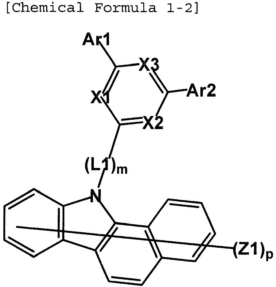


- In Chemical Formulas 1-1 to 1-4,
- X1 to X3, L1, m, Ar1, and Ar2 are the same as those defined in Chemical Formula 1,
- Z1 is deuterium,
- p' is an integer of 0 to 8, and
- p is an integer of 0 to 10.
- According to the exemplary embodiment of the present specification, Chemical Formula 1 is represented by the following Chemical Formula 1-5.

- In Chemical Formula 1-5, Cy1, Cy2, L1, m, Ar1, and Ar2 are the same as defined in Chemical Formula 1 according to the aforementioned exemplary embodiment.
- According to the exemplary embodiment of the present specification, in Chemical Formula 1, L1 is a substituted or unsubstituted monocyclic or polycyclic arylene group having 6 to 30 carbon atoms.
- According to the exemplary embodiment of the present specification, in Chemical Formula 1, L1 is a substituted or unsubstituted monocyclic arylene group having 6 to 30 carbon atoms. In this case, L1 may help an interaction between a structure including Cy1 and Cy2 and a structure including X1 to X3 to help the bipolar type to be stably maintained.
- According to another exemplary embodiment of the present specification, L1 is a substituted or unsubstituted monocyclic arylene group having 6 to 24 carbon atoms.
- According to another exemplary embodiment of the present specification, L1 is a substituted or unsubstituted phenylene group; or a substituted or unsubstituted biphenylene group.
- According to another exemplary embodiment of the present specification, L1 is a substituted or unsubstituted phenylene group; a substituted or unsubstituted biphenylene group; a substituted or unsubstituted terphenylene group; or a substituted or unsubstituted quaterphenylene group.
- According to one exemplary embodiment of the present specification, m is 1.
- According to another exemplary embodiment, m is 2.
- According to another exemplary embodiment, m is 3.
- According to another exemplary embodiment, m is 4.
- According to another exemplary embodiment of the present specification, L1 is a phenylene group; a biphenylene group; a terphenylene group; or a quaterphenylene group.
- According to another exemplary embodiment of the present specification, L1 is a phenylene group; or a biphenylene group, and m is 1 or 2, and in the case where m is 2, L1s are the same as or different from each other.
- In one exemplary embodiment of the present specification, (L1)m is represented by the following Chemical Formula 3.

- In Chemical Formula 3,
- R is a substituent group,
- a is an integer of 1 to 4,
in the case where a is an integer of 2 to 4, 2 to 4 Rs are the same as or different from each other, - m is an integer of 1 to 4, and
- The substituent group R may be selected from the aforementioned examples of the substituent group.
- According to the exemplary embodiment of the present specification, in the case where (L1)m is Chemical Formula 3, a cycle including Cy1 and Cy2 and a cycle including X1 to X3 may be connected in a linear form to structurally connect the p type and the n type and thus increase an interaction thereof, thereby stably serving as the bipolar type.
- According to the exemplary embodiment of the present specification, the compound represented by Chemical Formula 1 is represented by any one of the following Chemical Formulas 1-6 to 1-9.


- In Chemical Formulas 1-6 to 1-9,
- X1 to X3 are the same as or different from each other, and are each independently N or CH,
at least one of X1 to X3 is N, - Ar5 and Ar6 are the same as or different from each other, and are each independently hydrogen; deuterium; a substituted or unsubstituted alkyl group having 1 to 20 carbon atoms; a substituted or unsubstituted monocyclic or polycyclic aryl group having 6 to 30 carbon atoms; or a substituted or unsubstituted monocyclic or polycyclic heteroaryl group having 2 to 30 carbon atoms, or are bonded to a phenyl group to form a cycle,
- R is a substituent group,
a is an integer of 1 to 4,
in the case where a is an integer of 2 to 4, 2 to 4 Rs are the same as or different from each other, - m is an integer of 1 to 4, and
- According to another exemplary embodiment of the present specification, Ar5 and Ar6 are the same as or different from each other, and are each independently hydrogen; deuterium; a substituted or unsubstituted alkyl group having 1 to 10 carbon atoms; a substituted or unsubstituted monocyclic or polycyclic aryl group having 6 to 20 carbon atoms; or a substituted or unsubstituted monocyclic or polycyclic heteroaryl group having 2 to 20 carbon atoms, or are bonded to a phenyl group to form a cycle.
- According to another exemplary embodiment of the present specification, Ar5 and Ar6 are the same as or different from each other, and are each independently hydrogen; deuterium; a substituted or unsubstituted alkyl group having 1 to 5 carbon atoms; a substituted or unsubstituted monocyclic or polycyclic aryl group having 6 to 10 carbon atoms; or a substituted or unsubstituted monocyclic or polycyclic heteroaryl group having 2 to 10 carbon atoms, or are bonded to a phenyl group to form a cycle.
- Formation of the cycle by bonding to the phenyl group means formation of a condensation cycle by bonding the phenyl group and Ar5 or Ar6, and in this case, the structure including X1 to X3 may be substituted by a polycycle. In the present specification, the cycle may be an aliphatic hydrocarbon cycle, an aromatic hydrocarbon cycle, an aliphatic heterocycle, an aromatic heterocycle, or the like.
- According to another exemplary embodiment of the present specification, Ar5 and Ar6 are the same as or different from each other, and are each independently hydrogen; a substituted or unsubstituted methyl group; a substituted or unsubstituted phenyl group; a substituted or unsubstituted biphenyl group; or a substituted or unsubstituted naphthyl group, or are bonded to a phenyl group to form a substituted or unsubstituted naphthalene cycle, a substituted or unsubstituted triphenylene cycle, a substituted or unsubstituted fluorene cycle; or a substituted or unsubstituted phenanthrene cycle.
- According to another exemplary embodiment of the present specification, Ar5 and Ar6 are the same as or different from each other, and are each independently a methyl group; a triphenylmethyl group; a phenyl group; a naphthyl group; or a biphenyl group, or are bonded to a phenyl group to form a naphthalene cycle; a triphenylene cycle; a fluorene cycle substituted by a phenyl group; or a phenanthrene cycle.
- According to the exemplary embodiment of the present specification, in Chemical Formula 1, Ar1 and Ar2 are the same as or different from each other, and are each independently selected from the group consisting of a substituted or unsubstituted monocyclic or polycyclic aryl group having 6 to 20 carbon atoms; and a substituted or unsubstituted monocyclic or polycyclic heteroaryl group having 2 to 20 carbon atoms.
- According to another exemplary embodiment of the present specification, Ar1 and Ar2 are the same as or different from each other, and are each independently a substituted or unsubstituted phenyl group; a substituted or unsubstituted biphenyl group; a substituted or unsubstituted terphenyl group; a substituted or unsubstituted naphthyl group; a substituted or unsubstituted triphenylenyl group; a substituted or unsubstituted fluorenyl group; or a substituted or unsubstituted phenanthrenyl group.
- According to another exemplary embodiment of the present specification, Ar1 and Ar2 are the same as or different from each other, and are each independently a phenyl group; a biphenyl group; a terphenyl group; a naphthyl group; a triphenylenyl group; a fluorenyl group; or a phenanthrenyl group, and the phenyl group, the biphenyl group, the terphenyl group, the naphthyl group, the triphenylenyl group, the fluorenyl group, and the threnyl group are unsubstituted or substituted by one or two or more substituent groups selected from the group consisting of a substituted or unsubstituted alkyl group and a substituted or unsubstituted aryl group.
- According to another exemplary embodiment of the present specification, Ar1 and Ar2 are the same as or different from each other, and are each independently selected from the group consisting of a phenyl group; a phenyl group substituted by a methyl group; a phenyl group substituted by a triphenylmethyl group; a phenyl group substituted by a naphthyl group; a phenyl group substituted by a phenyl group; a phenyl group substituted by a terphenyl group; a biphenyl group; a biphenyl group substituted by a phenyl group; a naphthyl group; a triphenylenyl group; a fluorenyl group substituted by a phenyl group; and a phenanthrenyl group.
- According to the exemplary embodiment of the present specification, Ar1 and Ar2 are the same as or different from each other, and are each independently any one of the following substituent groups.


 is a portion connected to X1 to X3 of Chemical Formula 1.
- According to the exemplary embodiment of the present specification, p' is 0.
- According to one exemplary embodiment, p is 0.
- According to the exemplary embodiment of the present specification, the compound represented by Chemical Formula 1 is represented by any one of the following compounds.
- According to one exemplary embodiment, the compound represented by Chemical Formula 1-1 is represented by any one of the following Chemical Formulas 1-1-1 to 1-1-37.
- According to another exemplary embodiment, the compound represented by Chemical Formula 1-2 is represented by any one of the following Chemical Formulas 1-2-1 to 1-2-8.
- According to another exemplary embodiment, the compound represented by Chemical Formula 1-3 is represented by any one of the following Chemical Formulas 1-3-1 to 1-3-8.
- According to another exemplary embodiment, the compound represented by Chemical Formula 1-4 is represented by any one of the following Chemical Formulas 1-4-1 to 1-4-8.
Chemical Formula 1-1-1 Chemical Formula 1-1-2 

Chemical Formula 1-1-3 Chemical Formula 1-1-4 

Chemical Formula 1-1-5 Chemical Formula 1-1-6 

Chemical Formula 1-1-7 Chemical Formula 1-1-8 

Chemical Formula 1-1-9 Chemical Formula 1-1-10 

Chemical Formula 1-1-11 Chemical Formula 1-1-12 

Chemical Formula 1-1-13 Chemical Formula 1-1-14 

Chemical Formula 1-1-15 Chemical Formula 1-1-16 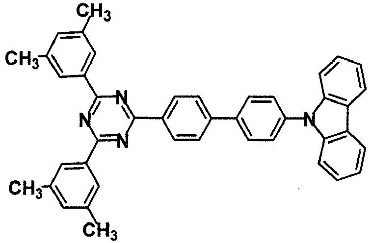

Chemical Formula 1-1-17 Chemical Formula 1-1-18 

Chemical Formula 1-1-19 Chemical Formula 1-1-20 

Chemical Formula 1-1-21 Chemical Formula 1-1-22 

Chemical Formula 1-1-23 Chemical Formula 1-1-24 

Chemical Formula 1-1-25 Chemical Formula 1-1-26 

Chemical Formula 1-1-27 Chemical Formula 1-1-28 

Chemical Formula 1-1-29 Chemical Formula 1-1-30 

Chemical Formula 1-1-31 Chemical Formula 1-1-32 

Chemical Formula 1-1-33 Chemical Formula 1-1-34 

Chemical Formula 1-1-35 Chemical Formula 1-1-36 

Chemical Formula 1-1-37 
Chemical Formula 1-2-1 Chemical Formula 1-2-2 

Chemical Formula 1-2-3 Chemical Formula 1-2-4 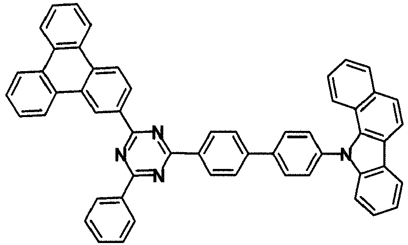

Chemical Formula 1-2-5 Chemical Formula 1-2-6 

Chemical Formula 1-2-7 Chemical Formula 1-2-8 

Chemical Formula 1-3-1 Chemical Formula 1-3-2 

Chemical Formula 1-3-3 Chemical Formula 1-3-4 

Chemical Formula 1-3-5 Chemical Formula 1-3-6 

Chemical Formula 1-3-7 Chemical Formula 1-3-8 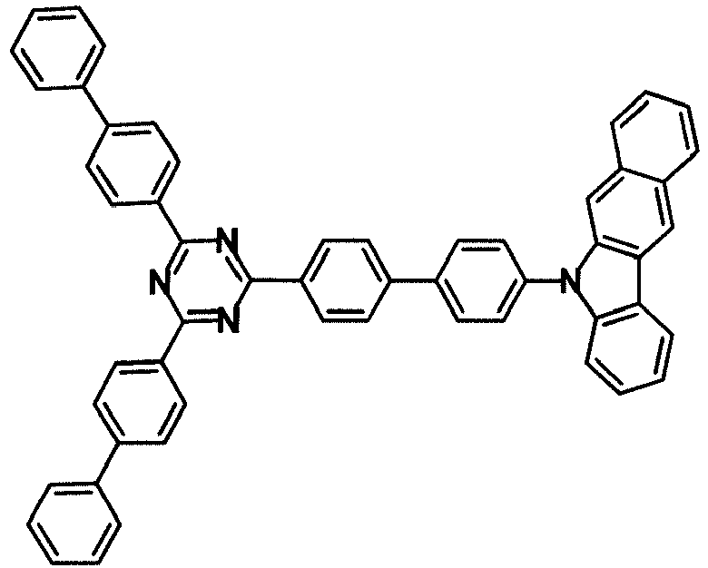

Chemical Formula 1-4-1 Chemical Formula 1-4-2 

Chemical Formula 1-4-3 Chemical Formula 1-4-4 

Chemical Formula 1-4-5 Chemical Formula 1-4-6 

Chemical Formula 1-4-7 Chemical Formula 1-4-8 

- According to the exemplary embodiment of the present specification, in Chemical Formula 2, Ar3 and Ar4 are the same as or different from each other, and are each independently a substituted or unsubstituted monocyclic or polycyclic aryl group having 6 to 25 carbon atoms; or a substituted or unsubstituted monocyclic or polycyclic heteroaryl group having 2 to 25 carbon atoms, or are bonded to each other to form a substituted or unsubstituted cycle.
- According to another exemplary embodiment of the present specification, Ar3 and Ar4 are the same as or different from each other, and are each independently a substituted or unsubstituted phenyl group; a substituted or unsubstituted biphenyl group; a substituted or unsubstituted fluorenyl group; a substituted or unsubstituted spirobifluorenyl group; or a substituted or unsubstituted dibenzofuran group, or are bonded to each other to form a substituted or unsubstituted dihydroacridine structure.
- According to another exemplary embodiment of the present specification, Ar3 and Ar4 are the same as or different from each other, and are each independently a phenyl group; a biphenyl group; a spirobifluorenyl group; a phenyl group substituted by a phenyl group; a fluorenyl group substituted by a methyl group; or a dibenzofuran group, or are bonded to each other to form a dihydroacridine structure substituted by a substituent group selected from the group consisting of a phenyl group and an alkyl group.
- According to the exemplary embodiment of the present specification, in Chemical Formula 2, Ar3 and Ar4 may be bonded to each other to form substituted or unsubstituted 9,10-dihydroacridine.
- According to another exemplary embodiment of the present specification, Ar3 and Ar4 may be bonded to each other to form 9,10-dihydroacridine substituted by a methyl group; or 9,10-dihydroacridine substituted by a phenyl group and a methyl group.
- According to the exemplary embodiment of the present specification, in Chemical Formula 2, L2 is a substituted or unsubstituted monocyclic or polycyclic arylene group having 6 to 20 carbon atoms.
- According to another exemplary embodiment of the present specification, L2 is a substituted or unsubstituted monocyclic or polycyclic arylene group having 6 to 15 carbon atoms.
- According to another exemplary embodiment of the present specification, L2 is a substituted or unsubstituted phenylene group.
- According to another exemplary embodiment of the present specification, L2 is a substituted or unsubstituted phenylene group, and n is 0 or 1.
- According to one exemplary embodiment of the present specification, L2 is a substituted or unsubstituted phenylene group, or n is 0.
- According to another exemplary embodiment of the present specification, L2 is a phenylene group.
- According to another exemplary embodiment of the present specification, (L2)n is a direct bond; or a substituted or unsubstituted phenylene group. According to another exemplary embodiment, (L2)n is a direct bond; or a phenylene group.
- According to the exemplary embodiment of the present specification,


- In the present specification,means a portion bonded to (L2)n in Chemical Formula 2.

- In the exemplary embodiment of the present specification,

- In another exemplary embodiment,

- In another exemplary embodiment,

- In another exemplary embodiment,


- According to the exemplary embodiment of the present specification, the compound represented by Chemical Formula 2 is represented by any one of the following Chemical Formulas 2-1 to 2-45.
Chemical Formula 2-1 Chemical Formula 2-2 Chemical Formula 2-3 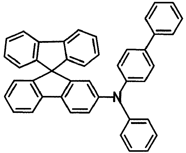


Chemical Formula 2-4 Chemical Formula 2-5 Chemical Formula 2-6 


Chemical Formula 2-7 Chemical Formula 2-8 Chemical Formula 2-9 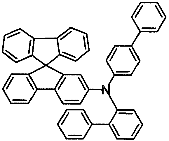


Chemical Formula 2-10 Chemical Formula 2-11 Chemical Formula 2-12 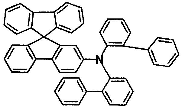


Chemical Formula 2-13 Chemical Formula 2-14 Chemical Formula 2-15 


Chemical Formula 2-16 Chemical Formula 2-17 Chemical Formula 2-18 


Chemical Formula 2-19 Chemical Formula 2-20 Chemical Formula 2-21 


Chemical Formula 2-22 Chemical Formula 2-23 Chemical Formula 2-24 


Chemical Formula 2-25 Chemical Formula 2-26 Chemical Formula 2-27 


Chemical Formula 2-28 Chemical Formula 2-29 Chemical Formula 2-30 


Chemical Formula 2-31 Chemical Formula 2-32 Chemical Formula 2-33 
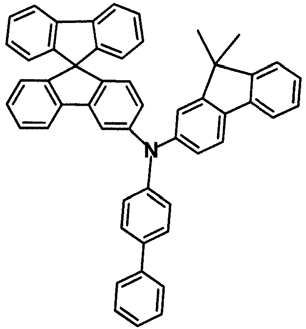
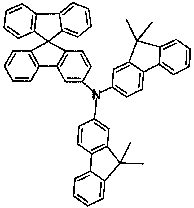
Chemical Formula 2-34 Chemical Formula 2-35 Chemical Formula 2-36 


Chemical Formula 2-37 Chemical Formula 2-38 Chemical Formula 2-39 


Chemical Formula 2-40 Chemical Formula 2-41 Chemical Formula 2-42 


Chemical Formula 2-43 Chemical Formula 2-44 Chemical Formula 2-45 


- In one exemplary embodiment of the present specification, the organic material layer including the compound represented by Chemical Formula 1 is the electron transport layer, the compound represented by Chemical Formula 1 is represented by Chemical Formula 1-1-19, and the organic material layer including the compound represented by Chemical Formula 2 is the electron blocking layer.
- In one exemplary embodiment, the organic material layer including the compound represented by Chemical Formula 2 is the electron blocking layer, and the compound represented by Chemical Formula 2 is represented by Chemical Formula 2-16. In another exemplary embodiment, the organic material layer including the compound represented by Chemical Formula 2 is the electron blocking layer, and the compound represented by Chemical Formula 2 is represented by Chemical Formula 2-18.
- In the exemplary embodiment of the present specification, the organic material layer including the compound represented by Chemical Formula 1 may further include an n-type dopant.
- In the exemplary embodiment of the present specification, the n-type dopant includes alkali metal, an alkali metal compound, alkali earth metal, or an alkali earth metal compound, or a combination thereof.
- In another exemplary embodiment, the n-type dopant may be one or two or more selected from the group consisting of Li, Na, K, Rb, Cs, Mg, Ca, Sr, Ba, La, Nd, Sm, Eu, Tb, Yb, LiF, Li2O, CsF, or the following compounds, but is not limited thereto.


- In the exemplary embodiment of the present specification, the compound represented by Chemical Formula 1 and the n-type dopant may be laminated on the organic light emitting device at a weight ratio of 9 : 1 to 1 : 9.
- In one exemplary embodiment, the compound represented by Chemical Formula 1 and the n-type dopant may be laminated on the organic light emitting device at a weight ratio of 1 : 1.
- The organic light emitting device of the present specification may be manufactured by a material and a method known in the art, except that the electron transport layer and the electron blocking layer are included.
- For example, the organic light emitting device of the present specification may be manufactured by sequentially laminating the anode, the organic material layer, and the cathode on a substrate. In this case, the organic light emitting device may be manufactured by depositing a metal, metal oxides having conductivity, or an alloy thereof on the substrate by using a physical vapor deposition (PVD) method such as a sputtering method or an e-beam evaporation method to form the anode, forming the organic material layer including the hole injection layer, the hole transport layer, the electron blocking layer, the light emitting layer, the electron transport layer, and the electron injection layer thereon, and then depositing a material that can be used as the cathode thereon. In addition to the aforementioned method, the organic light emitting device may be manufactured by sequentially depositing a cathode material, the organic material layer, and an anode material on the substrate. In addition to the aforementioned method, the organic light emitting device may be manufactured by sequentially depositing the anode material, the organic material layer, and the cathode material on the substrate.
- The organic material layer of the organic light emitting device of the present specification may have a multilayered structure where one or more organic material layers are laminated.
- In the exemplary embodiment of the present specification, the organic light emitting device may further include one layer or two or more layers selected from the group consisting of the hole injection layer, the hole transport layer, the electron transport layer, the electron injection layer, the electron blocking layer, and the hole blocking layer.
- For example, the structure of the organic light emitting device of the present specification may have a structure illustrated in
FIG. 1 or 2 , but is not limited thereto. -
FIG. 1 illustrates a structure of an organic light emitting device where ananode 201, ahole transport layer 301, anelectron blocking layer 401, alight emitting layer 501, anelectron transport layer 601, and acathode 701 are sequentially laminated on asubstrate 101.FIG. 1 is the exemplified structure according to the exemplary embodiment of the present specification, and may further include another organic material layer. InFIG. 1 , the compound represented by Chemical Formula 2 is included in theelectron blocking layer 401, and the compound represented by Chemical Formula 1 is included in theelectron transport layer 601. -
FIG. 2 illustrates a structure of an organic light emitting device where theanode 201, thehole transport layer 301, theelectron blocking layer 401, thelight emitting layer 501, theelectron transport layer 601, anelectron injection layer 801, and thecathode 701 are sequentially laminated on thesubstrate 101. InFIG. 2 , the compound represented by Chemical Formula 2 may be included in theelectron blocking layer 401, and the compound represented by Chemical Formula 1 may be included in theelectron transport layer 601. Further, the compound represented by Chemical Formula 2 may be included in theelectron blocking layer 401, and the compound represented by Chemical Formula 1 may be included in theelectron injection layer 801. Further, the compound represented by Chemical Formula 2 may be included in theelectron blocking layer 401, and the compound represented by Chemical Formula 1 may be included in theelectron transport layer 601 and theelectron injection layer 801. -
FIGS. 1 and 2 are the exemplified structures according to the exemplary embodiment of the present specification, and may further include other organic material layers. - In the case where the organic light emitting device includes a plurality of organic material layers, the organic material layers may be formed of the same material or different materials.
- As the anode material, in general, it is preferable to use a material having a large work function so as to smoothly inject holes into the organic material layer. Specific examples of the anode material that may be used in the present invention include metals such as vanadium, chrome, copper, zinc, and gold, or an alloy thereof; metal oxides such as zinc oxides, indium oxides, indium tin oxides (ITO), and indium zinc oxides (IZO); a combination of metals and oxides, such as ZnO:Al or SNO2:Sb; conductive polymers such as poly(3-methylthiophene), poly[3,4-(ethylene-1,2-dioxy)thiophene] (PEDOT), polypyrrole, and polyaniline, and the like, but are not limited thereto.
- It is preferable that the cathode material be, in general, a material having a small work function so as to easily inject electrons into the organic material layer. Specific examples of the cathode material include metals such as magnesium, calcium, sodium, potassium, titanium, indium, yttrium, lithium, gadolinium, aluminum, silver, tin, and lead, or an alloy thereof; a multilayered structure material such as LiF/Al or LiO2/Al, and the like, but are not limited thereto.
- The hole injection material is a layer injecting the holes from the electrode, and it is preferable that the hole injection material be a compound which has an ability of transporting the holes to have a hole injection effect from the anode and an excellent hole injection effect to the light emitting layer or the light emitting material, prevents movement of the exciton generated in the light emitting layer to the electron injection layer or the electron injection material, and has an excellent thin film forming ability. It is preferable that a highest occupied molecular orbital (HOMO) of the hole injection material be between the work function of the anode material and a HOMO of a peripheral organic material layer. Specific examples of the hole injection material include metal porphyrine, oligothiophene, an arylamine-based organic material, a hexanitrilehexaazatriphenylene-based organic material, a quinacridone-based organic material, a perylene-based organic material, anthraquinone, polyaniline, a polythiophene-based conductive polymer, and the like, but are not limited thereto.
- The hole transport layer is a layer receiving the holes from the hole injection layer and transporting the holes to the light emitting layer, the hole transport material is a material capable of receiving the holes from the anode or the hole injection layer and transporting the holes to the light emitting layer, and a material having large mobility to the holes is suitable as the hole transport material. Specific examples thereof include an arylamine-based organic material, a conductive polymer, a block copolymer in which a conjugate portion and a non-conjugate portion are present together, and the like, but are not limited thereto.
- The light emitting material is a material that receives and combines the holes and the electrons from the hole transport layer and the electron transport layer, such that light in a visible light region is emitted, and it is preferable to use a material having excellent quantum efficiency to fluorescence or phosphorescence. Specific examples thereof include a 8-hydroxy-quinoline aluminum complex (Alq3); a carbazole-based compound; a dimerized styryl compound; BAlq; a 10-hydroxybenzoquinoline-metal compound; benzoxazole, benzthiazole, and benzimidazole-based compounds; a poly(p-phenylenevinylene) (PPV)-based polymer; a spiro compound; polyfluorene, lubrene, and the like, but are not limited thereto.
- The light emitting layer may include a host material and a dopant material. Examples of the host material include a condensation aromatic ring derivative, a hetero-ring-containing compound, or the like. Specific examples of the compensation aromatic ring derivative include an anthracene derivative, a pyrene derivative, a naphthalene derivative, a pentacene derivative, a phenanthrene compound, a fluoranthene compound, and the like, and specific examples of the hetero-ring-containing compound include a carbazole derivative, a dibenzofuran derivative, a ladder-type furan compound, a pyrimidine derivative, and the like, but the examples are not limited thereto.
- Examples of the dopant material include an organic compound, a metal, or a metal compound.
- Examples of the organic compound as the dopant material include an aromatic amine derivative, a styrylamine compound, a boron complex, a fluoranthene compound, and the like. Specifically, the aromatic amine derivative is a compensation aromatic ring derivative having a substituted or unsubstituted arylamino group, examples thereof include pyrene, anthracene, chrysene, and periflanthene having the arylamino group, the styrylamine compound is a compound where at least one arylvinyl group is substituted in substituted or unsubstituted arylamine, and in the styrylamine compound, one or two or more substituent groups selected from the group consisting of an aryl group, a silyl group, an alkyl group, a cycloalkyl group, and an arylamino group are substituted or unsubstituted. Specific examples thereof include styrylamine, styryldiamine, styryltriamine, styryltetraamine, and the like, but are not limited thereto. Further, a general metal or metal compound may be used as the metal or the metal compound, and specifically, a metal complex may be used. Further, examples of the metal complex include an iridium complex, a platinum complex, and the like, but are not limited thereto.
- The electron injection layer is a layer injecting the electrons from the electrode, and a compound which has an ability of transporting the electrons, an electron injection effect from the cathode, and an excellent electron injection effect to the light emitting layer or the light emitting material, prevents movement of an exciton generated in the light emitting layer to the hole injection layer, and has an excellent thin film forming ability is preferable. Specific examples thereof include fluorenone, anthraquinodimethane, diphenoquinone, thiopyran dioxide, oxazole, oxadiazole, triazole, imidazole, perylene tetracarboxylic acid, fluorenylidene methane, anthrone, and the like, and derivatives thereof, a metal complex compound, a nitrogen-containing 5-membered cycle derivative, and the like, but are not limited thereto.
- Examples of the metal complex compound include 8-hydroxyquinolinato lithium, bis(8-hydroxyquinolinato)zinc, bis(8-hydroxyquinolinato)copper, bis(8-hydroxyquinolinato)manganese, tris(8-hydroxyquinolinato)aluminum, tris(2-methyl-8-hydroxyquinolinato)aluminum, tris(8-hydroxyquinolinato)gallium, bis(10-hydroxybenzo[h]quinolinato)beryllium, bis(10-hydroxybenzo[h]quinolinato)zinc, bis(2-methyl-8-quinolinato)chlorogallium, bis(2-methyl-8-quinolinato)(o-cresolato)gallium, bis(2-methyl-8-quinolinato)(1-naphtholato)aluminum, bis(2-methyl-8-quinolinato)(2-naphtholato)gallium, and the like, but are not limited thereto.
- The hole blocking layer is a layer preventing holes from reaching the cathode, and in general, may be formed under the same condition as the hole injection layer. Specific examples thereof include an oxadiazole derivative, a triazole derivative, a phenanthroline derivative, BCP, an aluminum complex, and the like, but are not limited thereto. The organic light emitting device according to the present specification may be a top emission type, a bottom emission type, or a both-sided emission type according to the used material.
- Further, the organic light emitting device according to the present specification may be a normal type where a lower electrode is the anode and an upper electrode is the cathode, or may be an inverted type where the lower electrode is the cathode and the upper electrode is the anode.
- The structure according to the exemplary embodiment of the present specification may act even in an organic electronic device including an organic solar cell, an organic photoconductor, an organic transistor, and the like by the principle that is similar to the principle applied to the organic light emitting device.
- Hereinafter, the present specification will be described in detail through Examples. However, the Examples according to the present specification may be modified in various other forms, and the scope of the present specification is not interpreted to be limited to the Examples described in detail below. The Examples of the present specification are provided so that a person with ordinary skill in the art may fully understand the present specification.
- The glass substrate (corning 7059 glass) on which the thin film of indium tin oxide (ITO) was applied at a thickness of 1,000 Å was immersed in distilled water having the detergent dissolved therein, and washed by the ultrasonic wave. In this case, the detergent used herein was the product commercially available from Fischer Co. and distilled water used herein was one which had been twice filtered by using the filter commercially available from Millipore Co. ITO was washed for 30 minutes, and washing with ultrasonic waves was then repeated twice for 10 minutes by using distilled water. After the completion of washing with distilled water, washing with ultrasonic waves was performed by using solvents such as isopropyl alcohol, acetone, and methanol, and the resulting product was dried and transported to the plasma washing machine. Further, the substrate was dry-washed by using the oxygen plasma for 5 minutes, and then transported to the vacuum deposition machine.
- Hexanitrile hexaazatriphenylene (hereinafter, referred to as "HAT") that was the compound of the following Chemical Formula was deposited under the heat vacuum in a thickness of 100 Å on the prepared ITO transparent electrode to form the thin film. The interfacial property between the substrate and the hole injection layer can be improved by this thin film. Subsequently, the compound of Chemical Formula HT-1 was deposited in a thickness of 800 Å on the thin film to form the hole transport layer, and the compound of Chemical Formula 2-16 was deposited in a thickness of 200 A thereon to form the electron blocking layer.
- Subsequently, 10 wt% of the compound of Chemical Formula PD-1 was doped onto the compound of Chemical Formula PH-1 to form the light emitting layer in a thickness of 300 Å. The electron transport layer material of Chemical Formula 1-1-1 and lithium quinolate (LiQ) were deposited under vacuum as at a weight ratio of 1:1 on the light emitting layer to form the electronic injection and transport layer in a thickness of 300 Å. Lithium fluoride (LiF) in a thickness of 12 Å and aluminum in a thickness of 2,000 Å were subsequently deposited on the electron transport layer to form the cathode.
- In the aforementioned process, the deposition rate of the organic material was maintained at 0.3 to 0.8 Å/sec. Further, the deposition rate of lithium fluoride of the cathode was maintained at 0.3 Å/sec, and the deposition rate of aluminum was maintained at 1.5 to 2.5 Å/sec. The degree of vacuum during deposition was maintained at 1 to 3 x 10⁻⁷.


- The organic light emitting device was manufactured by the same method as Example 1, except that Chemical Formula 2-3 was used instead of Chemical Formula 2-16 in Example 1.
- The organic light emitting device was manufactured by the same method as Example 1, except that Chemical Formula 2-18 was used instead of Chemical Formula 2-16 in Example 1.
- The organic light emitting device was manufactured by the same method as Example 1, except that Chemical Formula 2-4 was used instead of Chemical Formula 2-16 in Example 1.
- The organic light emitting device was manufactured by the same method as Example 1, except that Chemical Formula 1-1-26 was used instead of Chemical Formula 1-1-1 in Example 1.
- The organic light emitting device was manufactured by the same method as Example 2, except that Chemical Formula 1-1-26 was used instead of Chemical Formula 1-1-1 in Example 2.
- The organic light emitting device was manufactured by the same method as Example 3, except that Chemical Formula 1-1-26 was used instead of Chemical Formula 1-1-1 in Example 3.
- The organic light emitting device was manufactured by the same method as Example 4, except that Chemical Formula 1-1-26 was used instead of Chemical Formula 1-1-1 in Example 4.
- The organic light emitting device was manufactured by the same method as Example 1, except that Chemical Formula 1-1-27 was used instead of Chemical Formula 1-1-1 in Example 1.
- The organic light emitting device was manufactured by the same method as Example 2, except that Chemical Formula 1-1-27 was used instead of Chemical Formula 1-1-1 in Example 2.
- The organic light emitting device was manufactured by the same method as Example 3, except that Chemical Formula 1-1-27 was used instead of Chemical Formula 1-1-1 in Example 3.
- The organic light emitting device was manufactured by the same method as Example 4, except that Chemical Formula 1-1-27 was used instead of Chemical Formula 1-1-1 in Example 4.
- The organic light emitting device was manufactured by the same method as Example 1, except that Chemical Formula 1-1-14 was used instead of Chemical Formula 1-1-1 in Example 1.
- The organic light emitting device was manufactured by the same method as Example 2, except that Chemical Formula 1-1-14 was used instead of Chemical Formula 1-1-1 in Example 2.
- The organic light emitting device was manufactured by the same method as Example 3, except that Chemical Formula 1-1-14 was used instead of Chemical Formula 1-1-1 in Example 3.
- The organic light emitting device was manufactured by the same method as Example 4, except that Chemical Formula 1-1-14 was used instead of Chemical Formula 1-1-1 in Example 4.
- The organic light emitting device was manufactured by the same method as Example 1, except that Chemical Formula 1-1-19 was used instead of Chemical Formula 1-1-1 in Example 1.
- The organic light emitting device was manufactured by the same method as Example 2, except that Chemical Formula 1-1-19 was used instead of Chemical Formula 1-1-1 in Example 2.
- The organic light emitting device was manufactured by the same method as Example 3, except that Chemical Formula 1-1-19 was used instead of Chemical Formula 1-1-1 in Example 3.
- The organic light emitting device was manufactured by the same method as Example 4, except that Chemical Formula 1-1-19 was used instead of Chemical Formula 1-1-1 in Example 4.
- The organic light emitting device was manufactured by the same method as Example 1, except that Chemical Formula 1-4-4 was used instead of Chemical Formula 1-1-1 in Example 1.
- The organic light emitting device was manufactured by the same method as Example 2, except that Chemical Formula 1-4-4 was used instead of Chemical Formula 1-1-1 in Example 2.
- The organic light emitting device was manufactured by the same method as Example 3, except that Chemical Formula 1-4-4 was used instead of Chemical Formula 1-1-1 in Example 3.
- The organic light emitting device was manufactured by the same method as Example 4, except that Chemical Formula 1-4-4 was used instead of Chemical Formula 1-1-1 in Example 4.
- The organic light emitting device was manufactured by the same method as Example 1, except that the following Chemical Formula ET-1 was used instead of Chemical Formula 1-1-1 in Example 1.

- The organic light emitting device was manufactured by the same method as Example 2, except that Chemical Formula ET-1 was used instead of Chemical Formula 1-1-1 in Example 2.
- The organic light emitting device was manufactured by the same method as Example 3, except that Chemical Formula ET-1 was used instead of Chemical Formula 1-1-1 in Example 3.
- The organic light emitting device was manufactured by the same method as Example 4, except that Chemical Formula ET-1 was used instead of Chemical Formula 1-1-1 in Example 4.
- The organic light emitting device was manufactured by the same method as Example 1, except that the following Chemical Formula ET-2 was used instead of Chemical Formula 1-1-1 in Example 1.

- The organic light emitting device was manufactured by the same method as Example 2, except that Chemical Formula ET-2 was used instead of Chemical Formula 1-1-1 in Example 2.
- The organic light emitting device was manufactured by the same method as Example 3, except that Chemical Formula ET-2 was used instead of Chemical Formula 1-1-1 in Example 3.
- The organic light emitting device was manufactured by the same method as Example 4, except that Chemical Formula ET-2 was used instead of Chemical Formula 1-1-1 in Example 4.
- The organic light emitting device was manufactured by the same method as Example 1, except that the following Chemical Formula ET-3 was used instead of Chemical Formula 1-1-1 in Example 1.

- The organic light emitting device was manufactured by the same method as Example 2, except that Chemical Formula ET-3 was used instead of Chemical Formula 1-1-1 in Example 2.
- The organic light emitting device was manufactured by the same method as Example 3, except that Chemical Formula ET-3 was used instead of Chemical Formula 1-1-1 in Example 3.
- The organic light emitting device was manufactured by the same method as Example 4, except that Chemical Formula ET-3 was used instead of Chemical Formula 1-1-1 in Example 4.
- The organic light emitting device was manufactured by the same method as Example 1, except that the following Chemical Formula ET-4 was used instead of Chemical Formula 1-1-1 in Example 1.

- The organic light emitting device was manufactured by the same method as Example 2, except that Chemical Formula ET-4 was used instead of Chemical Formula 1-1-1 in Example 2.
- The organic light emitting device was manufactured by the same method as Example 3, except that Chemical Formula ET-4 was used instead of Chemical Formula 1-1-1 in Example 3.
- The organic light emitting device was manufactured by the same method as Example 4, except that Chemical Formula ET-4 was used instead of Chemical Formula 1-1-1 in Example 4.
- The organic light emitting device was manufactured by the same method as Example 1, except that the following Chemical Formula ET-5 was used instead of Chemical Formula 1-1-1 in Example 1.

- The organic light emitting device was manufactured by the same method as Example 2, except that Chemical Formula ET-5 was used instead of Chemical Formula 1-1-1 in Example 2.
- The organic light emitting device was manufactured by the same method as Example 3, except that Chemical Formula ET-5 was used instead of Chemical Formula 1-1-1 in Example 3.
- The organic light emitting device was manufactured by the same method as Example 4, except that Chemical Formula ET-5 was used instead of Chemical Formula 1-1-1 in Example 4.
- The organic light emitting device was manufactured by the same method as Example 1, except that the following Chemical Formula ET-6 was used instead of Chemical Formula 1-1-1 in Example 1.

- The organic light emitting device was manufactured by the same method as Example 2, except that Chemical Formula ET-6 was used instead of Chemical Formula 1-1-1 in Example 2.
- The organic light emitting device was manufactured by the same method as Example 3, except that Chemical Formula ET-6 was used instead of Chemical Formula 1-1-1 in Example 3.
- The organic light emitting device was manufactured by the same method as Example 4, except that Chemical Formula ET-6 was used instead of Chemical Formula 1-1-1 in Example 4.
- The organic light emitting device was manufactured by the same method as Example 1, except that Chemical Formula EB-1 was used instead of Chemical Formula 2-16 in Example 1.


- The organic light emitting device was manufactured by the same method as Example 5, except that Chemical Formula EB-1 was used instead of Chemical Formula 2-16 in Example 5.
- The organic light emitting device was manufactured by the same method as Example 9, except that Chemical Formula EB-1 was used instead of Chemical Formula 2-16 in Example 9.
- The organic light emitting device was manufactured by the same method as Example 13, except that Chemical Formula EB-1 was used instead of Chemical Formula 2-16 in Example 13.
- The organic light emitting device was manufactured by the same method as Example 17, except that Chemical Formula EB-1 was used instead of Chemical Formula 2-16 in Example 17.
- The organic light emitting device was manufactured by the same method as Example 21, except that Chemical Formula EB-1 was used instead of Chemical Formula 2-16 in Example 21.
- The organic light emitting device was manufactured by the same method as Example 1, except that Chemical Formula EB-2 was used instead of Chemical Formula 2-16 in Example 1.

- The organic light emitting device was manufactured by the same method as Example 5, except that Chemical Formula EB-2 was used instead of Chemical Formula 2-16 in Example 5.
- The organic light emitting device was manufactured by the same method as Example 9, except that Chemical Formula EB-2 was used instead of Chemical Formula 2-16 in Example 9.
- The organic light emitting device was manufactured by the same method as Example 13, except that Chemical Formula EB-2 was used instead of Chemical Formula 2-16 in Example 13.
- The organic light emitting device was manufactured by the same method as Example 17, except that Chemical Formula EB-2 was used instead of Chemical Formula 2-16 in Example 17.
- The organic light emitting device was manufactured by the same method as Example 21, except that Chemical Formula EB-2 was used instead of Chemical Formula 2-16 in Example 21.
- The organic light emitting device was manufactured by the same method as Example 1, except that the compound of ET-1 and Chemical Formula EB-1 were used instead of Chemical Formula 1-1-1 and Chemical Formula 2-16 in Example 1, respectively.
- The organic light emitting device was manufactured by the same method as Example 1, except that the compound of ET-1 and Chemical Formula EB-2 were used instead of Chemical Formula 1-1-1 and Chemical Formula 2-16 in Example 1, respectively.
- The organic light emitting device was manufactured by the same method as Example 1, except that the compound of ET-2 and Chemical Formula EB-1 were used instead of Chemical Formula 1-1-1 and Chemical Formula 2-16 in Example 1, respectively.
- The organic light emitting device was manufactured by the same method as Example 1, except that the compound of ET-2 and Chemical Formula EB-2 were used instead of Chemical Formula 1-1-1 and Chemical Formula 2-16 in Example 1, respectively.
- The organic light emitting device was manufactured by the same method as Example 1, except that the compound of ET-3 and Chemical Formula EB-1 were used instead of Chemical Formula 1-1-1 and Chemical Formula 2-16 in Example 1, respectively.
- The organic light emitting device was manufactured by the same method as Example 1, except that the compound of ET-3 and Chemical Formula EB-2 were used instead of Chemical Formula 1-1-1 and Chemical Formula 2-16 in Example 1, respectively.
- The organic light emitting device was manufactured by the same method as Example 1, except that the compound of ET-4 and Chemical Formula EB-1 were used instead of Chemical Formula 1-1-1 and Chemical Formula 2-16 in Example 1, respectively.
- The organic light emitting device was manufactured by the same method as Example 1, except that the compound of ET-4 and Chemical Formula EB-2 were used instead of Chemical Formula 1-1-1 and Chemical Formula 2-16 in Example 1, respectively.
- The organic light emitting device was manufactured by the same method as Example 1, except that the compound of ET-5 and Chemical Formula EB-1 were used instead of Chemical Formula 1-1-1 and Chemical Formula 2-16 in Example 1, respectively.
- The organic light emitting device was manufactured by the same method as Example 1, except that the compound of ET-5 and Chemical Formula EB-2 were used instead of Chemical Formula 1-1-1 and Chemical Formula 2-16 in Example 1, respectively.
- The organic light emitting device was manufactured by the same method as Example 1, except that the compound of ET-6 and Chemical Formula EB-1 were used instead of Chemical Formula 1-1-1 and Chemical Formula 2-16 in Example 1, respectively.
- The organic light emitting device was manufactured by the same method as Example 1, except that the compound of ET-6 and Chemical Formula EB-2 were used instead of Chemical Formula 1-1-1 and Chemical Formula 2-16 in Example 1, respectively.
- The organic light emitting device was manufactured by the same method as Example 17, except that the electron blocking layer including Chemical Formula 2-16 was not formed and the compound of HT-1 was deposited in a thickness of 1,400 Å to form the hole transport layer in Example 17.
- The organic light emitting device was manufactured by the same method as Example 1, except that the following Chemical Formula ET-7 was used instead of Chemical Formula 1-1-1 in Example 1.


- The organic light emitting device was manufactured by the same method as Example 2, except that Chemical Formula ET-7 was used instead of Chemical Formula 1-1-1 in Example 2.
- The organic light emitting device was manufactured by the same method as Example 3, except that Chemical Formula ET-7 was used instead of Chemical Formula 1-1-1 in Example 3.
- The organic light emitting device was manufactured by the same method as Example 4, except that Chemical Formula ET-7 was used instead of Chemical Formula 1-1-1 in Example 4.
- The organic light emitting device was manufactured by the same method as Example 1, except that the following Chemical Formula ET-8 was used instead of Chemical Formula 1-1-1 in Example 1.

- The organic light emitting device was manufactured by the same method as Example 2, except that Chemical Formula ET-8 was used instead of Chemical Formula 1-1-1 in Example 2.
- The organic light emitting device was manufactured by the same method as Example 3, except that Chemical Formula ET-8 was used instead of Chemical Formula 1-1-1 in Example 3.
- The organic light emitting device was manufactured by the same method as Example 4, except that Chemical Formula ET-8 was used instead of Chemical Formula 1-1-1 in Example 4.
- The organic light emitting device was manufactured by the same method as Example 1, except that the following Chemical Formula ET-9 was used instead of Chemical Formula 1-1-1 in Example 1.

- The organic light emitting device was manufactured by the same method as Example 2, except that Chemical Formula ET-9 was used instead of Chemical Formula 1-1-1 in Example 2.
- The organic light emitting device was manufactured by the same method as Example 3, except that Chemical Formula ET-9 was used instead of Chemical Formula 1-1-1 in Example 3.
- The organic light emitting device was manufactured by the same method as Example 4, except that Chemical Formula ET-9 was used instead of Chemical Formula 1-1-1 in Example 4.
- The driving voltage and light emitting efficiency of the organic light emitting device manufactured by the aforementioned method were measured at the current density of 10 mA/cm2, and the time (LT98) at which brightness was 98% of initial brightness at the current density of 20 mA/cm2 was measured. The result is described in the following Table 1.
[Table 1] Voltage (V) Current efficiency (cd/A) Color coordinates (x,y) Life Time 98 at 20 mA/cm2 Experimental Example 1 4.40 71.2 (0.455, 0.533) 245 Experimental Example 2 4.21 73.1 (0.453, 0.537) 232 Experimental Example 3 4.72 68.5 (0.444, 0.536) 277 Experimental Example 4 4.51 67.3 (0.442, 0.542) 270 Experimental Example 5 4.47 69.2 (0.454, 0.534) 275 Experimental Example 6 4.30 70.1 (0.453, 0.529) 279 Experimental Example 7 4.80 65.5 (0.454, 0.536) 307 Experimental Example 8 4.60 65.0 (0.451, 0.547) 311 Experimental Example 9 4.51 73.1 (0.453, 0.523) 290 Experimental Example 10 4.44 72.0 (0.453, 0.538) 301 Experimental Example 11 4.85 69.7 (0.443, 0.534) 320 Experimental Example 12 4.77 67.7 (0.455, 0.537) 318 Experimental Example 13 4.42 70.1 (0.454, 0.533) 311 Experimental Example 14 4.34 69.3 (0.453, 0.537) 302 Experimental Example 15 4.55 67.1 (0.439, 0.536) 310 Experimental Example 16 4.41 65.5 (0.455, 0.539) 325 Experimental Example 17 4.22 68.1 (0.455, 0.545) 315 Experimental Example 18 4.24 68.3 (0.454, 0.546) 322 Experimental Example 19 4.35 66.0 (0.441, 0.537) 325 Experimental Example 20 4.01 64.4 (0.450, 0.541) 328 Experimental Example 21 4.0 74.1 (0.455, 0.545) 299 Experimental Example 22 4.20 72.9 (0.454, 0.546) 328 Experimental Example 23 4.11 74.4 (0.441, 0.537) 308 Experimental Example 24 4.03 71.2 (0.450, 0.541) 318 Comparative Example 1 4.51 64.1 (0.454, 0.532) 190 Comparative Example 2 4.33 66.1 (0.463, 0.538) 179 Comparative Example 3 4.75 59.1 (0.444, 0.536) 200 Comparative Example 4 4.66 61.0 (0.443, 0.542) 210 Comparative Example 5 4.44 55.0 (0.453, 0.533) 220 Comparative Example 6 4.45 48.1 (0.463, 0.539) 180 Comparative Example 7 4.69 51.1 (0.446, 0.537) 205 Comparative Example 8 4.59 58.0 (0.443, 0.542) 230 Comparative Example 9 4.34 51.0 (0.454, 0.543) 250 Comparative Example 10 4.40 45.0 (0.464, 0.533) 185 Comparative Example 11 4.58 49.1 (0.447, 0.536) 225 Comparative Example 12 4.44 49.5 (0.443, 0.543) 228 Comparative Example 13 4.74 59.0 (0.454, 0.532) 177 Comparative Example 14 4.80 51.0 (0.455, 0.533) 185 Comparative Example 15 5.01 55.0 (0.446, 0.535) 202 Comparative Example 16 4.94 55.5 (0.443, 0.544) 220 Comparative Example 17 4.31 70.1 (0.454, 0.532) 140 Comparative Example 18 4.33 68.1 (0.463, 0.538) 155 Comparative Example 19 4.65 59.3 (0.444, 0.536) 105 Comparative Example 20 4.51 63.0 (0.443, 0.542) 120 Comparative Example 21 5.01 48.1 (0.454, 0.532) 110 Comparative Example 22 5.11 42.0 (0.463, 0.548) 150 Comparative Example 23 4.98 51.9 (0.454, 0.536) 160 Comparative Example 24 4.67 48.0 (0.443, 0.542) 123 Comparative Example 25 4.36 55.0 (0.443, 0.542) 215 Comparative Example 26 4.42 55.0 (0.453, 0.533) 222 Comparative Example 27 4.41 48.1 (0.463, 0.539) 179 Comparative Example 28 4.29 51.2 (0.446, 0.537) 230 Comparative Example 29 4.45 57.9 (0.443, 0.542) 245 Comparative Example 30 4.34 52.0 (0.454, 0.543) 228 Comparative Example 31 4.75 70.0 (0.456, 0.532) 96 Comparative Example 32 4.99 66.0 (0.455, 0.532) 105 Comparative Example 33 6.15 48.1 (0.446, 0.536) 171 Comparative Example 34 5.11 55.6 (0.443, 0.534) 148 Comparative Example 35 6.05 64.4 (0.455, 0.532) 116 Comparative Example 36 7.10 77.1 (0.465, 0.538) 80 Comparative Example 37 6.60 67.2 (0.454, 0.532) 105 Comparative Example 38 6.35 69.1 (0.463, 0.537) 136 Comparative Example 39 6.55 66.1 (0.444, 0.536) 180 Comparative Example 40 4.66 71.0 (0.443, 0.542) 112 Comparative Example 41 6.02 53.0 (0.453, 0.523) 162 Comparative Example 42 5.99 65.0 (0.463, 0.539) 170 Comparative Example 43 6.69 55.0 (0.446, 0.537) 205 Comparative Example 44 7.10 68.0 (0.443, 0.542) 98 Comparative Example 45 6.95 62.0 (0.454, 0.543) 150 Comparative Example 46 6.77 65.0 (0.464, 0.533) 205 Comparative Example 47 5.98 58.0 (0.454, 0.532) 177 Comparative Example 48 6.09 70.0 (0.455, 0.533) 155 Comparative Example 49 7.02 40.6 (0.452, 0.546) 99 Comparative Example 50 4.55 55.0 (0.454, 0.532) 200 Comparative Example 51 4.41 61.1 (0.463, 0.538) 188 Comparative Example 52 4.82 51.1 (0.444, 0.536) 210 Comparative Example 53 4.75 54.0 (0.443, 0.542) 225 Comparative Example 54 4.69 52.0 (0.453, 0.532) 220 Comparative Example 55 4.55 58.2 (0.463, 0.538) 191 Comparative Example 56 5.01 49.1 (0.443, 0.535) 234 Comparative Example 57 4.91 51.1 (0.443, 0.543) 251 Comparative Example 58 4.44 68.2 (0.454, 0.532) 110 Comparative Example 59 4.39 70.1 (0.459, 0.535) 124 Comparative Example 60 4.74 64.3 (0.444, 0.535) 125 Comparative Example 61 4.69 66.0 (0.443, 0.542) 141 - As seen in Table 1, it can be confirmed that the organic light emitting device using the compound represented by Chemical Formula 1 as the electron transport material according to the exemplary embodiment of the present specification has high efficiency, a low driving voltage, and a long life-span as compared to the case where an existing electron transport material is used.
- This is because the compound represented by Chemical Formula 1 is a bipolar type including both a p type and an n type, so that hole leakage can be prevented and an exciton can be effectively confined in the light emitting layer.

in the case where r is 2 or more, two or more R2s are the same as or different from each other,
in the case where s is 2 or more, two or more R3s are the same as or different from each other, and
in the case where t is 2 or more, two or more R4s are the same as or different from each other.
Claims (15)
- An organic light emitting device comprising:an anode;a cathode;a light emitting layer provided between the anode and the cathode;an organic material layer including a compound represented by the following Chemical Formula 1 and provided between the cathode and the light emitting layer; andan organic material layer including a compound represented by the following Chemical Formula 2 and provided between the anode and the light emitting layer,
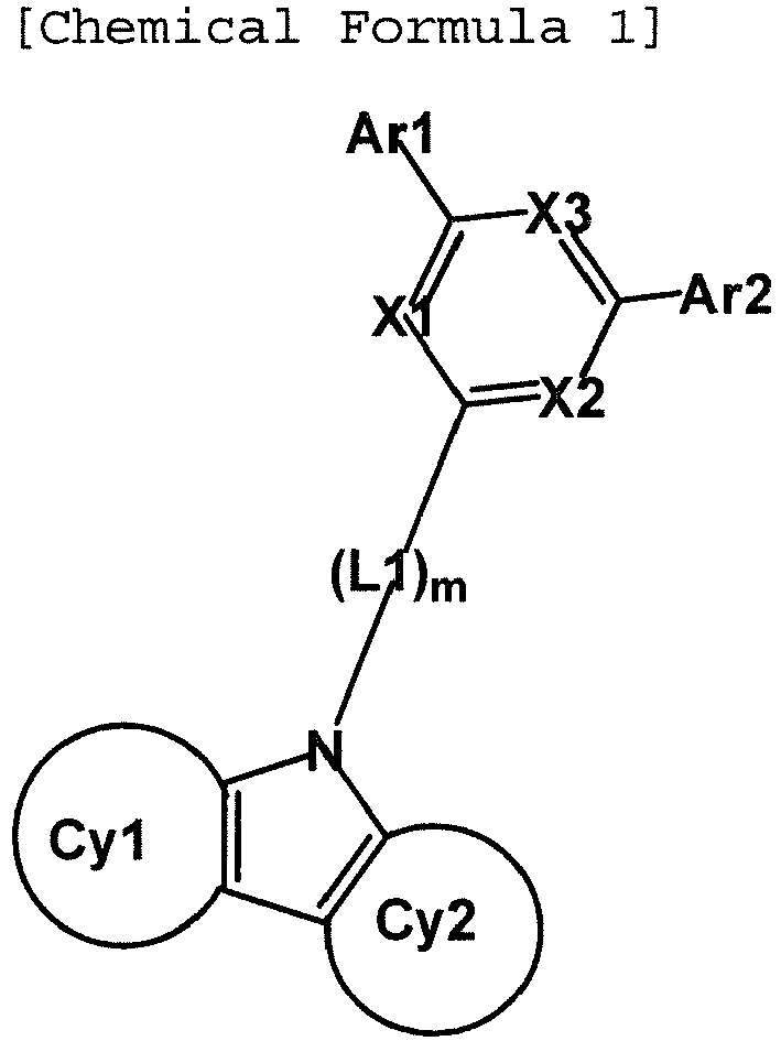 X1 to X3 are the same as or different from each other, and are each independently N or CH,at least one of X1 to X3 is N,Cy1 and Cy2 are the same as or different from each other, and are each independently a substituted or unsubstituted monocyclic or polycyclic aromatic cycle having 6 to 30 carbon atoms; or a substituted or unsubstituted monocyclic or polycyclic heterocycle having 2 to 30 carbon atoms,L1 is a substituted or unsubstituted monocyclic or polycyclic arylene group having 6 to 30 carbon atoms,m is an integer of 1 to 4,
in the case where m is an integer of 2 or more, two or more L1s are the same as or different from each other, andAr1 and Ar2 are the same as or different from each other, and are each independently a substituted or unsubstituted monocyclic or polycyclic aryl group having 6 to 30 carbon atoms; or a substituted or unsubstituted monocyclic or polycyclic heteroaryl group having 2 to 30 carbon atoms,
 Ar3 and Ar4 are the same as or different from each other, and are each independently hydrogen; deuterium; a substituted or unsubstituted monocyclic or polycyclic aryl group having 6 to 30 carbon atoms; or a substituted or unsubstituted monocyclic or polycyclic heteroaryl group having 2 to 30 carbon atoms, or are bonded to each other to form a substituted or unsubstituted cycle,L2 is a substituted or unsubstituted monocyclic or polycyclic arylene group having 6 to 30 carbon atoms,n is an integer of 0 to 5,in the case where n is 2 or more, two or more L2s are the same as or different from each other,R1 to R4 are the same as or different from each other, and are each independently hydrogen; deuterium; a substituted or unsubstituted straight-chained or branch-chained alkyl group having 1 to 30 carbon atoms; a substituted or unsubstituted monocyclic or polycyclic aryl group having 6 to 30 carbon atoms; or a substituted or unsubstituted monocyclic or polycyclic heteroaryl group having 2 to 30 carbon atoms, or adjacent groups are bonded to each other to form a substituted or unsubstituted aromatic cycle,q, r, and s are each an integer of 1 to 4,t is an integer of 1 to 3,in the case where q is 2 or more, two or more R1s are the same as or different from each other,
in the case where r is 2 or more, two or more R2s are the same as or different from each other,
in the case where s is 2 or more, two or more R3s are the same as or different from each other, and
in the case where t is 2 or more, two or more R4s are the same as or different from each other. - The organic light emitting device of claim 1, wherein the organic material layer including the compound represented by Chemical Formula 1 is an electron transport layer, an electron injection layer, or a layer simultaneously transporting and injecting electrons.
- The organic light emitting device of claim 1, wherein the organic material layer including the compound represented by Chemical Formula 2 is an electron blocking layer.
- The organic light emitting device of claim 1, wherein the organic material layer including the compound represented by Chemical Formula 2 is provided to come into contact with the light emitting layer.
- The organic light emitting device of claim 1, further comprising:one or two or more layers from the group consisting of an electron injection layer and an electron transport layer between the light emitting layer and the cathode.
- The organic light emitting device of claim 1, further comprising:one or two or more layers from the group consisting of a hole injection layer, a hole transport layer, and an electron blocking layer between the light emitting layer and the anode.
- The organic light emitting device of claim 1, wherein Cy1 and Cy2 are the same as or different from each other, and are each independently a substituted or unsubstituted benzene cycle; or a substituted or unsubstituted naphthalene cycle.
- The organic light emitting device of claim 1, wherein the compound represented by Chemical Formula 1 is a compound represented by any one of the following Chemical Formulas 1-1 to 1-4:


 X1 to X3, L1, m, Ar1, and Ar2 are the same as those defined in Chemical Formula 1,Z1 is deuterium,p' is an integer of 0 to 8, andp is an integer of 0 to 10.
 - The organic light emitting device of claim 1, wherein L1 is a substituted or unsubstituted phenylene group; a substituted or unsubstituted biphenylene group; a substituted or unsubstituted terphenylene group; or a substituted or unsubstituted quaterphenylene group.
- The organic light emitting device of claim 1, wherein Ar1 and Ar2 are the same as or different from each other, and are each independently a substituted or unsubstituted phenyl group; a substituted or unsubstituted biphenyl group; a substituted or unsubstituted terphenyl group; a substituted or unsubstituted naphthyl group; a substituted or unsubstituted triphenylenyl group; a substituted or unsubstituted fluorenyl group; or a substituted or unsubstituted phenanthrenyl group.
- The organic light emitting device of claim 1, wherein X1 to X3 are N.
- The organic light emitting device of claim 1, wherein the compound represented by Chemical Formula 1 is represented by any one of the following compounds:
Chemical Formula 1-1-1 Chemical Formula 1-1-2 

Chemical Formula 1-1-3 Chemical Formula 1-1-4 

Chemical Formula 1-1-5 Chemical Formula 1-1-6 

Chemical Formula 1-1-7 Chemical Formula 1-1-8 

Chemical Formula 1-1-9 Chemical Formula 1-1-10 

Chemical Formula 1-1-11 Chemical Formula 1-1-12 

Chemical Formula 1-1-13 Chemical Formula 1-1-14 

Chemical Formula 1-1-15 Chemical Formula 1-1-16 
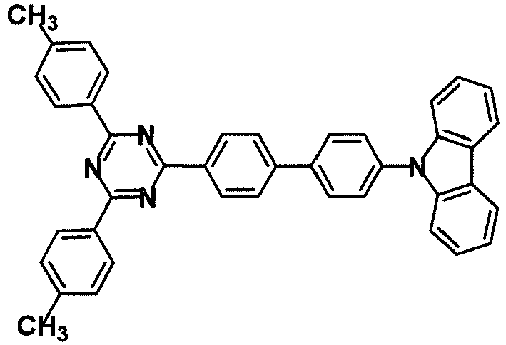
Chemical Formula 1-1-17 Chemical Formula 1-1-18 

Chemical Formula 1-1-19 Chemical Formula 1-1-20 

Chemical Formula 1-1-21 Chemical Formula 1-1-22 

Chemical Formula 1-1-23 Chemical Formula 1-1-24 

Chemical Formula 1-1-25 Chemical Formula 1-1-26 

Chemical Formula 1-1-27 Chemical Formula 1-1-28 
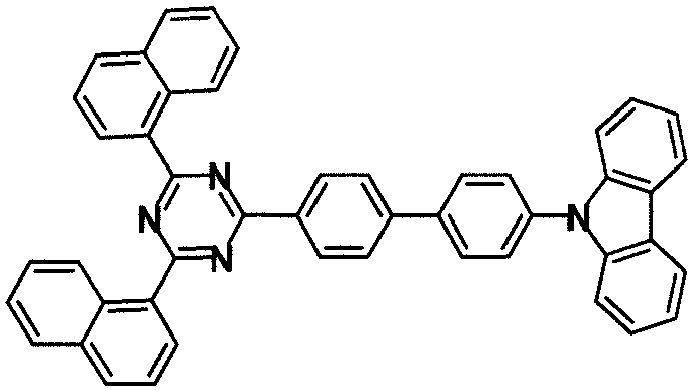
Chemical Formula 1-1-29 Chemical Formula 1-1-30 

Chemical Formula 1-1-31 Chemical Formula 1-1-32 

Chemical Formula 1-1-33 Chemical Formula 1-1-34 

Chemical Formula 1-1-35 Chemical Formula 1-1-36 

Chemical Formula 1-1-37 
Chemical Formula 1-2-1 Chemical Formula 1-2-2 

Chemical Formula 1-2-3 Chemical Formula 1-2-4 

Chemical Formula 1-2-5 Chemical Formula 1-2-6 

Chemical Formula 1-2-7 Chemical Formula 1-2-8 
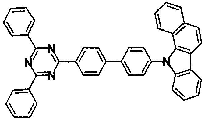
Chemical Formula 1-3-1 Chemical Formula 1-3-2 

Chemical Formula 1-3-3 Chemical Formula 1-3-4 

Chemical Formula 1-3-5 Chemical Formula 1-3-6 

Chemical Formula 1-3-7 Chemical Formula 1-3-8 

Chemical Formula 1-4-1 Chemical Formula 1-4-2 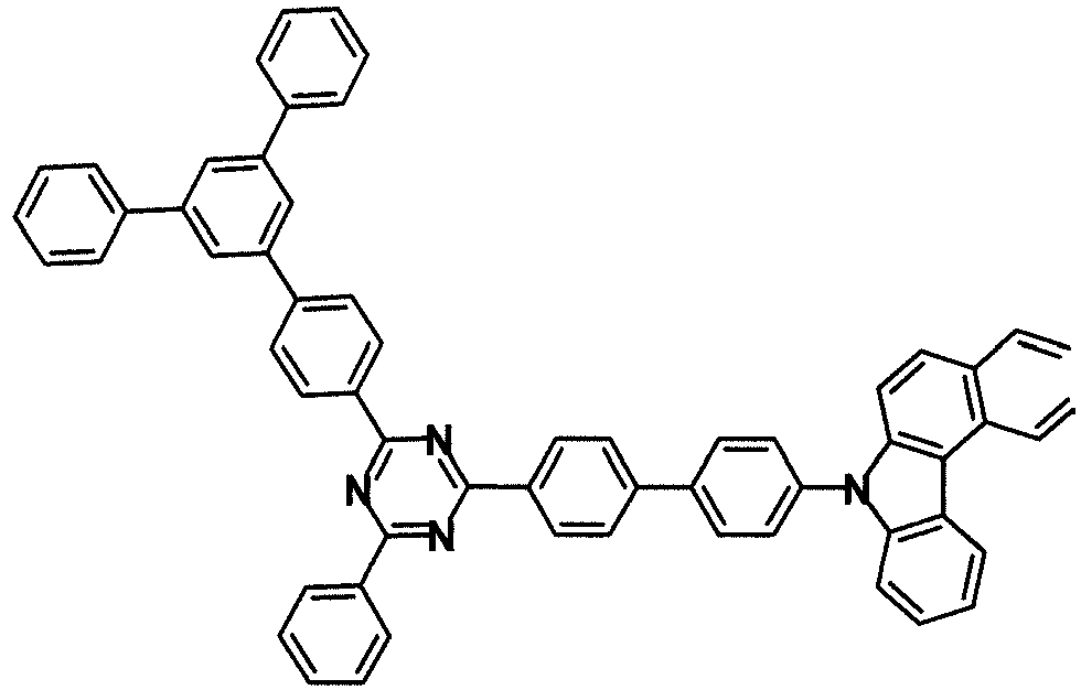

Chemical Formula 1-4-3 Chemical Formula 1-4-4 

Chemical Formula 1-4-5 Chemical Formula 1-4-6 

Chemical Formula 1-4-7 Chemical Formula 1-4-8 

- The organic light emitting device of claim 1, wherein Ar3 and Ar4 are the same as or different from each other, and are each independently a substituted or unsubstituted phenyl group; a substituted or unsubstituted biphenyl group; a substituted or unsubstituted fluorenyl group; a substituted or unsubstituted spirobifluorenyl group; or a substituted or unsubstituted dibenzofuran group, or are bonded to each other to form a substituted or unsubstituted dihydroacridine structure.
- The organic light emitting device of claim 1, wherein L2 is a substituted or unsubstituted phenylene group, or n is 0.
- The organic light emitting device of claim 1, wherein the compound represented by Chemical Formula 2 is represented by any one of the following Chemical Formulas 2-1 to 2-45:
Chemical Formula 2-1 Chemical Formula 2-2 Chemical Formula 2-3 


Chemical Formula 2-4 Chemical Formula 2-5 Chemical Formula 2-6 


Chemical Formula 2-7 Chemical Formula 2-8 Chemical Formula 2-9 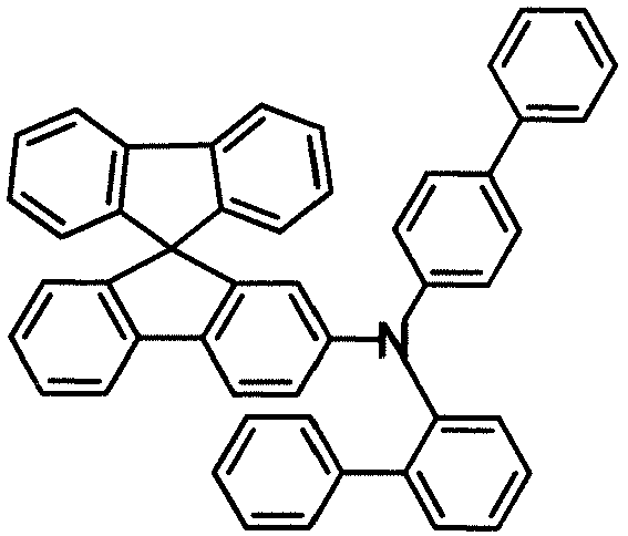


Chemical Formula 2-10 Chemical Formula 2-11 Chemical Formula 2-12 


Chemical Formula 2-13 Chemical Formula 2-14 Chemical Formula 2-15 


Chemical Formula 2-16 Chemical Formula 2-17 Chemical Formula 2-18 


Chemical Formula 2-19 Chemical Formula 2-20 Chemical Formula 2-21 


Chemical Formula 2-22 Chemical Formula 2-23 Chemical Formula 2-24 


Chemical Formula 2-25 Chemical Formula 2-26 Chemical Formula 2-27 


Chemical Formula 2-28 Chemical Formula 2-29 Chemical Formula 2-30 


Chemical Formula 2-31 Chemical Formula 2-32 Chemical Formula 2-33 
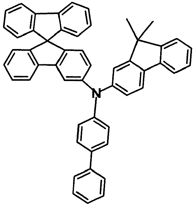

Chemical Formula 2-34 Chemical Formula 2-35 Chemical Formula 2-36 


Chemical Formula 2-37 Chemical Formula 2-38 Chemical Formula 2-39 


Chemical Formula 2-40 Chemical Formula 2-41 Chemical Formula 2-42 


Chemical Formula 2-43 Chemical Formula 2-44 Chemical Formula 2-45 


Applications Claiming Priority (3)
| Application Number | Priority Date | Filing Date | Title |
|---|---|---|---|
| KR20140132287 | 2014-10-01 | ||
| KR1020140146410A KR101709379B1 (en) | 2014-10-01 | 2014-10-27 | Organic light emitting device |
| PCT/KR2014/010323 WO2016052798A1 (en) | 2014-10-01 | 2014-10-31 | Organic light emitting element |
Publications (3)
| Publication Number | Publication Date |
|---|---|
| EP3202872A1 true EP3202872A1 (en) | 2017-08-09 |
| EP3202872A4 EP3202872A4 (en) | 2018-06-06 |
| EP3202872B1 EP3202872B1 (en) | 2021-12-01 |
Family
ID=55800636
Family Applications (1)
| Application Number | Title | Priority Date | Filing Date |
|---|---|---|---|
| EP14903217.9A Active EP3202872B1 (en) | 2014-10-01 | 2014-10-31 | Organic light emitting element |
Country Status (6)
| Country | Link |
|---|---|
| US (2) | US10714692B2 (en) |
| EP (1) | EP3202872B1 (en) |
| JP (1) | JP6443780B2 (en) |
| KR (2) | KR101709379B1 (en) |
| CN (1) | CN105684179B (en) |
| TW (1) | TWI543668B (en) |
Cited By (2)
| Publication number | Priority date | Publication date | Assignee | Title |
|---|---|---|---|---|
| EP3915982A4 (en) * | 2019-01-23 | 2022-01-26 | Soulbrain Co., Ltd. | COMPOUND AND ORGANIC ELECTROLUMINESCENT DEVICE COMPRISING THE SAME |
| EP4236652A3 (en) * | 2015-07-29 | 2023-09-13 | Merck Patent GmbH | Materials for organic electroluminescent devices |
Families Citing this family (25)
| Publication number | Priority date | Publication date | Assignee | Title |
|---|---|---|---|---|
| KR101879232B1 (en) * | 2015-08-07 | 2018-07-17 | 머티어리얼사이언스 주식회사 | Organic electroluminescent device |
| KR20250009554A (en) * | 2015-12-16 | 2025-01-17 | 메르크 파텐트 게엠베하 | Materials for organic electroluminescent devices |
| JP7051691B2 (en) * | 2016-02-05 | 2022-04-11 | メルク パテント ゲーエムベーハー | Materials for electronic devices |
| KR101999709B1 (en) * | 2016-03-21 | 2019-07-12 | 주식회사 엘지화학 | Organic light emitting device |
| EP3464244B1 (en) * | 2016-06-03 | 2021-11-17 | Merck Patent GmbH | Materials for organic electroluminescent devices |
| KR102672462B1 (en) * | 2017-03-31 | 2024-06-05 | 듀폰스페셜티머터리얼스코리아 유한회사 | Organic electroluminescent device |
| KR102154386B1 (en) * | 2017-06-16 | 2020-09-09 | 주식회사 엘지화학 | Compound, coating composition comprising the same, organic light emitting device using the same and method of manufacturing the same |
| KR102064646B1 (en) * | 2017-06-30 | 2020-01-09 | 주식회사 엘지화학 | Organic light emitting device |
| KR102448032B1 (en) | 2017-08-01 | 2022-09-28 | 삼성디스플레이 주식회사 | Organic light emitting device and electronic device including same |
| CN111032645B (en) * | 2018-01-22 | 2023-03-10 | 株式会社Lg化学 | Polycyclic compound and organic light-emitting device comprising same |
| KR102524650B1 (en) * | 2018-01-24 | 2023-04-21 | 삼성에스디아이 주식회사 | Compound, composition and organic optoelectronic device and display device |
| JP7049888B2 (en) * | 2018-03-29 | 2022-04-07 | 日本放送協会 | Organic electroluminescence elements, display devices, lighting devices |
| CN109251148A (en) * | 2018-09-11 | 2019-01-22 | 武汉华星光电半导体显示技术有限公司 | Coating molecular structure, production method and corresponding OLED device |
| KR102213664B1 (en) | 2018-11-28 | 2021-02-05 | 삼성에스디아이 주식회사 | Compound for optoelectronic device and organic optoelectronic device and display device |
| KR102748936B1 (en) * | 2019-12-27 | 2025-01-03 | 삼성디스플레이 주식회사 | Organic light emitting device and apparatus including the same |
| KR102887482B1 (en) * | 2019-12-30 | 2025-11-17 | 엘지디스플레이 주식회사 | Organic light emitting diode and orgnic light emitting device including the same |
| US12336425B2 (en) * | 2020-05-11 | 2025-06-17 | Samsung Display Co., Ltd. | Compound and light-emitting device including the same |
| US20220109112A1 (en) * | 2020-05-29 | 2022-04-07 | Lg Display Co., Ltd. | Organic light emitting device |
| CN114373872B (en) * | 2020-10-15 | 2025-05-06 | 江苏三月科技股份有限公司 | An organic electroluminescent device |
| KR102859887B1 (en) * | 2020-10-16 | 2025-09-12 | 주식회사 엘지화학 | Compound and organic light emitting device comprising same |
| KR102885087B1 (en) * | 2020-10-16 | 2025-11-11 | 주식회사 엘지화학 | Compound and organic light emitting device comprising same |
| KR20220094282A (en) * | 2020-12-28 | 2022-07-06 | 엘지디스플레이 주식회사 | Organic light emitting device |
| KR102864763B1 (en) * | 2021-12-30 | 2025-09-24 | 삼성에스디아이 주식회사 | Compound for organic optoelectronic device, composition for organic optoelectronic device, organic optoelectronic device and display device |
| KR102800062B1 (en) * | 2022-03-10 | 2025-04-29 | 주식회사 엘지화학 | Compound and organic light emitting device comprising same |
| CN114957144A (en) * | 2022-06-22 | 2022-08-30 | 华南理工大学 | A bipolar host material and its preparation method and application |
Family Cites Families (12)
| Publication number | Priority date | Publication date | Assignee | Title |
|---|---|---|---|---|
| US20090021336A1 (en) * | 2002-12-16 | 2009-01-22 | Energetics Technologies, Llc | Inductor for the excitation of polyharmonic rotating magnetic fields |
| JP5194596B2 (en) * | 2007-07-11 | 2013-05-08 | コニカミノルタホールディングス株式会社 | Organic electroluminescence element, display device and lighting device |
| DE102010045405A1 (en) * | 2010-09-15 | 2012-03-15 | Merck Patent Gmbh | Materials for organic electroluminescent devices |
| DE102010048608A1 (en) | 2010-10-15 | 2012-04-19 | Merck Patent Gmbh | Materials for organic electroluminescent devices |
| JP5964328B2 (en) | 2011-02-11 | 2016-08-03 | ユニバーサル ディスプレイ コーポレイション | ORGANIC LIGHT EMITTING DEVICE AND MATERIAL FOR USE IN THE ORGANIC LIGHT EMITTING DEVICE |
| KR101971895B1 (en) | 2011-05-12 | 2019-04-25 | 도레이 카부시키가이샤 | Light-emitting element material and light-emitting element |
| JP5565743B2 (en) * | 2011-07-15 | 2014-08-06 | 国立大学法人九州大学 | Organic electroluminescence device and compound used therefor |
| KR20130055216A (en) | 2011-11-18 | 2013-05-28 | 롬엔드하스전자재료코리아유한회사 | Novel organic electroluminescent compounds and organic electroluminescent device using the same |
| WO2013175747A1 (en) * | 2012-05-22 | 2013-11-28 | 出光興産株式会社 | Organic electroluminescent element |
| WO2014034791A1 (en) | 2012-08-31 | 2014-03-06 | 出光興産株式会社 | Organic electroluminescent element |
| KR101820865B1 (en) * | 2013-01-17 | 2018-01-22 | 삼성전자주식회사 | MATERIAL FOR ORGANIC OPTOELECTRONIC DEVICE, ORGANIC LiGHT EMITTING DIODE INCLUDING THE SAME AND DISPLAY INCLUDING THE ORGANIC LiGHT EMITTING DIODE |
| KR102244071B1 (en) * | 2014-05-02 | 2021-04-26 | 삼성디스플레이 주식회사 | Organic light emitting device |
-
2014
- 2014-10-27 KR KR1020140146410A patent/KR101709379B1/en active Active
- 2014-10-31 US US14/767,552 patent/US10714692B2/en active Active
- 2014-10-31 CN CN201480021952.XA patent/CN105684179B/en active Active
- 2014-10-31 TW TW103137728A patent/TWI543668B/en active
- 2014-10-31 EP EP14903217.9A patent/EP3202872B1/en active Active
- 2014-10-31 JP JP2017507828A patent/JP6443780B2/en active Active
-
2015
- 2015-09-09 KR KR1020150127742A patent/KR101927103B1/en active Active
-
2020
- 2020-05-29 US US16/888,395 patent/US11737354B2/en active Active
Cited By (3)
| Publication number | Priority date | Publication date | Assignee | Title |
|---|---|---|---|---|
| EP4236652A3 (en) * | 2015-07-29 | 2023-09-13 | Merck Patent GmbH | Materials for organic electroluminescent devices |
| EP3915982A4 (en) * | 2019-01-23 | 2022-01-26 | Soulbrain Co., Ltd. | COMPOUND AND ORGANIC ELECTROLUMINESCENT DEVICE COMPRISING THE SAME |
| US11374177B2 (en) | 2019-01-23 | 2022-06-28 | Soulbrain Co., Ltd. | Compound and organic light emitting device comprising the same |
Also Published As
| Publication number | Publication date |
|---|---|
| KR101927103B1 (en) | 2018-12-11 |
| JP6443780B2 (en) | 2018-12-26 |
| US10714692B2 (en) | 2020-07-14 |
| KR20160039522A (en) | 2016-04-11 |
| EP3202872B1 (en) | 2021-12-01 |
| CN105684179A (en) | 2016-06-15 |
| CN105684179B (en) | 2017-09-08 |
| TWI543668B (en) | 2016-07-21 |
| KR20160039535A (en) | 2016-04-11 |
| EP3202872A4 (en) | 2018-06-06 |
| US20160225993A1 (en) | 2016-08-04 |
| JP2017531309A (en) | 2017-10-19 |
| US20200295264A1 (en) | 2020-09-17 |
| US11737354B2 (en) | 2023-08-22 |
| KR101709379B1 (en) | 2017-02-23 |
| TW201615060A (en) | 2016-04-16 |
Similar Documents
| Publication | Publication Date | Title |
|---|---|---|
| EP3202872B1 (en) | Organic light emitting element | |
| EP3192847B1 (en) | Organic light emitting diode | |
| EP3192848B1 (en) | Organic light emitting diode | |
| EP3181657B1 (en) | Organic light-emitting element | |
| EP3312256B1 (en) | Organic light emitting device | |
| EP3222695A1 (en) | Organic light emitting diode | |
| CN110225909B (en) | Novel heterocyclic compound and organic light-emitting device comprising same | |
| EP3305771A2 (en) | Heterocyclic compound and organic light emitting device including same | |
| EP3360868B1 (en) | Spiro-type compound and organic light emitting diode comprising same | |
| EP3345891B1 (en) | Amine compound and organic light-emitting device comprising same | |
| EP3214084B1 (en) | Cyclic compound and organic light-emitting element comprising same | |
| WO2018225940A1 (en) | Novel heterocyclic compound and organic light-emitting element using same |
Legal Events
| Date | Code | Title | Description |
|---|---|---|---|
| STAA | Information on the status of an ep patent application or granted ep patent |
Free format text: STATUS: THE INTERNATIONAL PUBLICATION HAS BEEN MADE |
|
| PUAI | Public reference made under article 153(3) epc to a published international application that has entered the european phase |
Free format text: ORIGINAL CODE: 0009012 |
|
| STAA | Information on the status of an ep patent application or granted ep patent |
Free format text: STATUS: REQUEST FOR EXAMINATION WAS MADE |
|
| 17P | Request for examination filed |
Effective date: 20170222 |
|
| AK | Designated contracting states |
Kind code of ref document: A1 Designated state(s): AL AT BE BG CH CY CZ DE DK EE ES FI FR GB GR HR HU IE IS IT LI LT LU LV MC MK MT NL NO PL PT RO RS SE SI SK SM TR |
|
| AX | Request for extension of the european patent |
Extension state: BA ME |
|
| DAX | Request for extension of the european patent (deleted) | ||
| A4 | Supplementary search report drawn up and despatched |
Effective date: 20180509 |
|
| RIC1 | Information provided on ipc code assigned before grant |
Ipc: H01L 51/54 20060101ALI20180503BHEP Ipc: C07D 209/82 20060101ALI20180503BHEP Ipc: C07D 403/10 20060101ALI20180503BHEP Ipc: C09K 11/06 20060101AFI20180503BHEP Ipc: H01L 51/50 20060101ALI20180503BHEP |
|
| STAA | Information on the status of an ep patent application or granted ep patent |
Free format text: STATUS: EXAMINATION IS IN PROGRESS |
|
| 17Q | First examination report despatched |
Effective date: 20201002 |
|
| GRAP | Despatch of communication of intention to grant a patent |
Free format text: ORIGINAL CODE: EPIDOSNIGR1 |
|
| STAA | Information on the status of an ep patent application or granted ep patent |
Free format text: STATUS: GRANT OF PATENT IS INTENDED |
|
| RIC1 | Information provided on ipc code assigned before grant |
Ipc: C09K 11/06 20060101AFI20210630BHEP Ipc: C07D 403/10 20060101ALI20210630BHEP Ipc: C07D 209/82 20060101ALI20210630BHEP Ipc: H01L 51/54 20060101ALI20210630BHEP |
|
| INTG | Intention to grant announced |
Effective date: 20210722 |
|
| GRAS | Grant fee paid |
Free format text: ORIGINAL CODE: EPIDOSNIGR3 |
|
| GRAA | (expected) grant |
Free format text: ORIGINAL CODE: 0009210 |
|
| STAA | Information on the status of an ep patent application or granted ep patent |
Free format text: STATUS: THE PATENT HAS BEEN GRANTED |
|
| AK | Designated contracting states |
Kind code of ref document: B1 Designated state(s): AL AT BE BG CH CY CZ DE DK EE ES FI FR GB GR HR HU IE IS IT LI LT LU LV MC MK MT NL NO PL PT RO RS SE SI SK SM TR |
|
| REG | Reference to a national code |
Ref country code: GB Ref legal event code: FG4D |
|
| REG | Reference to a national code |
Ref country code: AT Ref legal event code: REF Ref document number: 1451767 Country of ref document: AT Kind code of ref document: T Effective date: 20211215 Ref country code: CH Ref legal event code: EP |
|
| REG | Reference to a national code |
Ref country code: IE Ref legal event code: FG4D |
|
| REG | Reference to a national code |
Ref country code: DE Ref legal event code: R096 Ref document number: 602014081587 Country of ref document: DE |
|
| REG | Reference to a national code |
Ref country code: LT Ref legal event code: MG9D |
|
| REG | Reference to a national code |
Ref country code: NL Ref legal event code: MP Effective date: 20211201 |
|
| REG | Reference to a national code |
Ref country code: AT Ref legal event code: MK05 Ref document number: 1451767 Country of ref document: AT Kind code of ref document: T Effective date: 20211201 |
|
| PG25 | Lapsed in a contracting state [announced via postgrant information from national office to epo] |
Ref country code: RS Free format text: LAPSE BECAUSE OF FAILURE TO SUBMIT A TRANSLATION OF THE DESCRIPTION OR TO PAY THE FEE WITHIN THE PRESCRIBED TIME-LIMIT Effective date: 20211201 Ref country code: LT Free format text: LAPSE BECAUSE OF FAILURE TO SUBMIT A TRANSLATION OF THE DESCRIPTION OR TO PAY THE FEE WITHIN THE PRESCRIBED TIME-LIMIT Effective date: 20211201 Ref country code: FI Free format text: LAPSE BECAUSE OF FAILURE TO SUBMIT A TRANSLATION OF THE DESCRIPTION OR TO PAY THE FEE WITHIN THE PRESCRIBED TIME-LIMIT Effective date: 20211201 Ref country code: BG Free format text: LAPSE BECAUSE OF FAILURE TO SUBMIT A TRANSLATION OF THE DESCRIPTION OR TO PAY THE FEE WITHIN THE PRESCRIBED TIME-LIMIT Effective date: 20220301 Ref country code: AT Free format text: LAPSE BECAUSE OF FAILURE TO SUBMIT A TRANSLATION OF THE DESCRIPTION OR TO PAY THE FEE WITHIN THE PRESCRIBED TIME-LIMIT Effective date: 20211201 |
|
| PG25 | Lapsed in a contracting state [announced via postgrant information from national office to epo] |
Ref country code: SE Free format text: LAPSE BECAUSE OF FAILURE TO SUBMIT A TRANSLATION OF THE DESCRIPTION OR TO PAY THE FEE WITHIN THE PRESCRIBED TIME-LIMIT Effective date: 20211201 Ref country code: PL Free format text: LAPSE BECAUSE OF FAILURE TO SUBMIT A TRANSLATION OF THE DESCRIPTION OR TO PAY THE FEE WITHIN THE PRESCRIBED TIME-LIMIT Effective date: 20211201 Ref country code: NO Free format text: LAPSE BECAUSE OF FAILURE TO SUBMIT A TRANSLATION OF THE DESCRIPTION OR TO PAY THE FEE WITHIN THE PRESCRIBED TIME-LIMIT Effective date: 20220301 Ref country code: LV Free format text: LAPSE BECAUSE OF FAILURE TO SUBMIT A TRANSLATION OF THE DESCRIPTION OR TO PAY THE FEE WITHIN THE PRESCRIBED TIME-LIMIT Effective date: 20211201 Ref country code: HR Free format text: LAPSE BECAUSE OF FAILURE TO SUBMIT A TRANSLATION OF THE DESCRIPTION OR TO PAY THE FEE WITHIN THE PRESCRIBED TIME-LIMIT Effective date: 20211201 Ref country code: GR Free format text: LAPSE BECAUSE OF FAILURE TO SUBMIT A TRANSLATION OF THE DESCRIPTION OR TO PAY THE FEE WITHIN THE PRESCRIBED TIME-LIMIT Effective date: 20220302 Ref country code: ES Free format text: LAPSE BECAUSE OF FAILURE TO SUBMIT A TRANSLATION OF THE DESCRIPTION OR TO PAY THE FEE WITHIN THE PRESCRIBED TIME-LIMIT Effective date: 20211201 |
|
| PG25 | Lapsed in a contracting state [announced via postgrant information from national office to epo] |
Ref country code: NL Free format text: LAPSE BECAUSE OF FAILURE TO SUBMIT A TRANSLATION OF THE DESCRIPTION OR TO PAY THE FEE WITHIN THE PRESCRIBED TIME-LIMIT Effective date: 20211201 |
|
| PG25 | Lapsed in a contracting state [announced via postgrant information from national office to epo] |
Ref country code: SM Free format text: LAPSE BECAUSE OF FAILURE TO SUBMIT A TRANSLATION OF THE DESCRIPTION OR TO PAY THE FEE WITHIN THE PRESCRIBED TIME-LIMIT Effective date: 20211201 Ref country code: SK Free format text: LAPSE BECAUSE OF FAILURE TO SUBMIT A TRANSLATION OF THE DESCRIPTION OR TO PAY THE FEE WITHIN THE PRESCRIBED TIME-LIMIT Effective date: 20211201 Ref country code: RO Free format text: LAPSE BECAUSE OF FAILURE TO SUBMIT A TRANSLATION OF THE DESCRIPTION OR TO PAY THE FEE WITHIN THE PRESCRIBED TIME-LIMIT Effective date: 20211201 Ref country code: PT Free format text: LAPSE BECAUSE OF FAILURE TO SUBMIT A TRANSLATION OF THE DESCRIPTION OR TO PAY THE FEE WITHIN THE PRESCRIBED TIME-LIMIT Effective date: 20220401 Ref country code: EE Free format text: LAPSE BECAUSE OF FAILURE TO SUBMIT A TRANSLATION OF THE DESCRIPTION OR TO PAY THE FEE WITHIN THE PRESCRIBED TIME-LIMIT Effective date: 20211201 Ref country code: CZ Free format text: LAPSE BECAUSE OF FAILURE TO SUBMIT A TRANSLATION OF THE DESCRIPTION OR TO PAY THE FEE WITHIN THE PRESCRIBED TIME-LIMIT Effective date: 20211201 |
|
| REG | Reference to a national code |
Ref country code: DE Ref legal event code: R097 Ref document number: 602014081587 Country of ref document: DE |
|
| PG25 | Lapsed in a contracting state [announced via postgrant information from national office to epo] |
Ref country code: IS Free format text: LAPSE BECAUSE OF FAILURE TO SUBMIT A TRANSLATION OF THE DESCRIPTION OR TO PAY THE FEE WITHIN THE PRESCRIBED TIME-LIMIT Effective date: 20220401 |
|
| PLBE | No opposition filed within time limit |
Free format text: ORIGINAL CODE: 0009261 |
|
| STAA | Information on the status of an ep patent application or granted ep patent |
Free format text: STATUS: NO OPPOSITION FILED WITHIN TIME LIMIT |
|
| PG25 | Lapsed in a contracting state [announced via postgrant information from national office to epo] |
Ref country code: DK Free format text: LAPSE BECAUSE OF FAILURE TO SUBMIT A TRANSLATION OF THE DESCRIPTION OR TO PAY THE FEE WITHIN THE PRESCRIBED TIME-LIMIT Effective date: 20211201 Ref country code: AL Free format text: LAPSE BECAUSE OF FAILURE TO SUBMIT A TRANSLATION OF THE DESCRIPTION OR TO PAY THE FEE WITHIN THE PRESCRIBED TIME-LIMIT Effective date: 20211201 |
|
| 26N | No opposition filed |
Effective date: 20220902 |
|
| PG25 | Lapsed in a contracting state [announced via postgrant information from national office to epo] |
Ref country code: SI Free format text: LAPSE BECAUSE OF FAILURE TO SUBMIT A TRANSLATION OF THE DESCRIPTION OR TO PAY THE FEE WITHIN THE PRESCRIBED TIME-LIMIT Effective date: 20211201 |
|
| PG25 | Lapsed in a contracting state [announced via postgrant information from national office to epo] |
Ref country code: MC Free format text: LAPSE BECAUSE OF FAILURE TO SUBMIT A TRANSLATION OF THE DESCRIPTION OR TO PAY THE FEE WITHIN THE PRESCRIBED TIME-LIMIT Effective date: 20211201 Ref country code: IT Free format text: LAPSE BECAUSE OF FAILURE TO SUBMIT A TRANSLATION OF THE DESCRIPTION OR TO PAY THE FEE WITHIN THE PRESCRIBED TIME-LIMIT Effective date: 20211201 |
|
| REG | Reference to a national code |
Ref country code: CH Ref legal event code: PL |
|
| REG | Reference to a national code |
Ref country code: BE Ref legal event code: MM Effective date: 20221031 |
|
| P01 | Opt-out of the competence of the unified patent court (upc) registered |
Effective date: 20230523 |
|
| PG25 | Lapsed in a contracting state [announced via postgrant information from national office to epo] |
Ref country code: LU Free format text: LAPSE BECAUSE OF NON-PAYMENT OF DUE FEES Effective date: 20221031 |
|
| PG25 | Lapsed in a contracting state [announced via postgrant information from national office to epo] |
Ref country code: LI Free format text: LAPSE BECAUSE OF NON-PAYMENT OF DUE FEES Effective date: 20221031 Ref country code: CH Free format text: LAPSE BECAUSE OF NON-PAYMENT OF DUE FEES Effective date: 20221031 |
|
| PG25 | Lapsed in a contracting state [announced via postgrant information from national office to epo] |
Ref country code: BE Free format text: LAPSE BECAUSE OF NON-PAYMENT OF DUE FEES Effective date: 20221031 |
|
| PG25 | Lapsed in a contracting state [announced via postgrant information from national office to epo] |
Ref country code: IE Free format text: LAPSE BECAUSE OF NON-PAYMENT OF DUE FEES Effective date: 20221031 |
|
| PG25 | Lapsed in a contracting state [announced via postgrant information from national office to epo] |
Ref country code: HU Free format text: LAPSE BECAUSE OF FAILURE TO SUBMIT A TRANSLATION OF THE DESCRIPTION OR TO PAY THE FEE WITHIN THE PRESCRIBED TIME-LIMIT; INVALID AB INITIO Effective date: 20141031 |
|
| PG25 | Lapsed in a contracting state [announced via postgrant information from national office to epo] |
Ref country code: CY Free format text: LAPSE BECAUSE OF FAILURE TO SUBMIT A TRANSLATION OF THE DESCRIPTION OR TO PAY THE FEE WITHIN THE PRESCRIBED TIME-LIMIT Effective date: 20211201 |
|
| PG25 | Lapsed in a contracting state [announced via postgrant information from national office to epo] |
Ref country code: MK Free format text: LAPSE BECAUSE OF FAILURE TO SUBMIT A TRANSLATION OF THE DESCRIPTION OR TO PAY THE FEE WITHIN THE PRESCRIBED TIME-LIMIT Effective date: 20211201 |
|
| PG25 | Lapsed in a contracting state [announced via postgrant information from national office to epo] |
Ref country code: TR Free format text: LAPSE BECAUSE OF FAILURE TO SUBMIT A TRANSLATION OF THE DESCRIPTION OR TO PAY THE FEE WITHIN THE PRESCRIBED TIME-LIMIT Effective date: 20211201 |
|
| PG25 | Lapsed in a contracting state [announced via postgrant information from national office to epo] |
Ref country code: MT Free format text: LAPSE BECAUSE OF FAILURE TO SUBMIT A TRANSLATION OF THE DESCRIPTION OR TO PAY THE FEE WITHIN THE PRESCRIBED TIME-LIMIT Effective date: 20211201 |
|
| PGFP | Annual fee paid to national office [announced via postgrant information from national office to epo] |
Ref country code: GB Payment date: 20250922 Year of fee payment: 12 |
|
| PGFP | Annual fee paid to national office [announced via postgrant information from national office to epo] |
Ref country code: FR Payment date: 20250925 Year of fee payment: 12 |
|
| PGFP | Annual fee paid to national office [announced via postgrant information from national office to epo] |
Ref country code: DE Payment date: 20250922 Year of fee payment: 12 |