EP3202601A1 - Pneumatic valve adaptor - Google Patents
Pneumatic valve adaptor Download PDFInfo
- Publication number
- EP3202601A1 EP3202601A1 EP16160842.7A EP16160842A EP3202601A1 EP 3202601 A1 EP3202601 A1 EP 3202601A1 EP 16160842 A EP16160842 A EP 16160842A EP 3202601 A1 EP3202601 A1 EP 3202601A1
- Authority
- EP
- European Patent Office
- Prior art keywords
- valve
- pneumatic valve
- fast
- rotatable joint
- adaptor
- Prior art date
- Legal status (The legal status is an assumption and is not a legal conclusion. Google has not performed a legal analysis and makes no representation as to the accuracy of the status listed.)
- Withdrawn
Links
Images







Classifications
-
- B—PERFORMING OPERATIONS; TRANSPORTING
- B60—VEHICLES IN GENERAL
- B60C—VEHICLE TYRES; TYRE INFLATION; TYRE CHANGING; CONNECTING VALVES TO INFLATABLE ELASTIC BODIES IN GENERAL; DEVICES OR ARRANGEMENTS RELATED TO TYRES
- B60C29/00—Arrangements of tyre-inflating valves to tyres or rims; Accessories for tyre-inflating valves, not otherwise provided for
- B60C29/06—Accessories for tyre-inflating valves, e.g. housings, guards, covers for valve caps, locks, not otherwise provided for
- B60C29/064—Hose connections for pneumatic tyres, e.g. to spare wheels
-
- F—MECHANICAL ENGINEERING; LIGHTING; HEATING; WEAPONS; BLASTING
- F16—ENGINEERING ELEMENTS AND UNITS; GENERAL MEASURES FOR PRODUCING AND MAINTAINING EFFECTIVE FUNCTIONING OF MACHINES OR INSTALLATIONS; THERMAL INSULATION IN GENERAL
- F16L—PIPES; JOINTS OR FITTINGS FOR PIPES; SUPPORTS FOR PIPES, CABLES OR PROTECTIVE TUBING; MEANS FOR THERMAL INSULATION IN GENERAL
- F16L37/00—Couplings of the quick-acting type
- F16L37/08—Couplings of the quick-acting type in which the connection between abutting or axially overlapping ends is maintained by locking members
- F16L37/10—Couplings of the quick-acting type in which the connection between abutting or axially overlapping ends is maintained by locking members using a rotary external sleeve or ring on one part
- F16L37/107—Bayonet-type couplings
-
- B—PERFORMING OPERATIONS; TRANSPORTING
- B29—WORKING OF PLASTICS; WORKING OF SUBSTANCES IN A PLASTIC STATE IN GENERAL
- B29C—SHAPING OR JOINING OF PLASTICS; SHAPING OF MATERIAL IN A PLASTIC STATE, NOT OTHERWISE PROVIDED FOR; AFTER-TREATMENT OF THE SHAPED PRODUCTS, e.g. REPAIRING
- B29C73/00—Repairing of articles made from plastics or substances in a plastic state, e.g. of articles shaped or produced by using techniques covered by this subclass or subclass B29D
- B29C73/16—Auto-repairing or self-sealing arrangements or agents
- B29C73/166—Devices or methods for introducing sealing compositions into articles
-
- B—PERFORMING OPERATIONS; TRANSPORTING
- B60—VEHICLES IN GENERAL
- B60C—VEHICLE TYRES; TYRE INFLATION; TYRE CHANGING; CONNECTING VALVES TO INFLATABLE ELASTIC BODIES IN GENERAL; DEVICES OR ARRANGEMENTS RELATED TO TYRES
- B60C29/00—Arrangements of tyre-inflating valves to tyres or rims; Accessories for tyre-inflating valves, not otherwise provided for
- B60C29/06—Accessories for tyre-inflating valves, e.g. housings, guards, covers for valve caps, locks, not otherwise provided for
- B60C29/062—Accessories for tyre-inflating valves, e.g. housings, guards, covers for valve caps, locks, not otherwise provided for for filling a tyre with particular materials, e.g. liquids
-
- F—MECHANICAL ENGINEERING; LIGHTING; HEATING; WEAPONS; BLASTING
- F04—POSITIVE - DISPLACEMENT MACHINES FOR LIQUIDS; PUMPS FOR LIQUIDS OR ELASTIC FLUIDS
- F04B—POSITIVE-DISPLACEMENT MACHINES FOR LIQUIDS; PUMPS
- F04B33/00—Pumps actuated by muscle power, e.g. for inflating
- F04B33/005—Pumps actuated by muscle power, e.g. for inflating specially adapted for inflating tyres of non-motorised vehicles, e.g. cycles, tricycles
-
- F—MECHANICAL ENGINEERING; LIGHTING; HEATING; WEAPONS; BLASTING
- F16—ENGINEERING ELEMENTS AND UNITS; GENERAL MEASURES FOR PRODUCING AND MAINTAINING EFFECTIVE FUNCTIONING OF MACHINES OR INSTALLATIONS; THERMAL INSULATION IN GENERAL
- F16L—PIPES; JOINTS OR FITTINGS FOR PIPES; SUPPORTS FOR PIPES, CABLES OR PROTECTIVE TUBING; MEANS FOR THERMAL INSULATION IN GENERAL
- F16L37/00—Couplings of the quick-acting type
- F16L37/24—Couplings of the quick-acting type in which the connection is made by inserting one member axially into the other and rotating it to a limited extent, e.g. with bayonet-action
- F16L37/244—Couplings of the quick-acting type in which the connection is made by inserting one member axially into the other and rotating it to a limited extent, e.g. with bayonet-action the coupling being co-axial with the pipe
- F16L37/248—Bayonet-type couplings
-
- B—PERFORMING OPERATIONS; TRANSPORTING
- B29—WORKING OF PLASTICS; WORKING OF SUBSTANCES IN A PLASTIC STATE IN GENERAL
- B29L—INDEXING SCHEME ASSOCIATED WITH SUBCLASS B29C, RELATING TO PARTICULAR ARTICLES
- B29L2030/00—Pneumatic or solid tyres or parts thereof
Definitions
- the present invention relates to a pneumatic valve adaptor, and in particular to a leakage-resistant pneumatic valve adaptor that is applicable to supplying gaseous or liquid tire sealant and comprises a fast-releasable gas source connector that can be quickly connected to or disconnected from a valve coupler through a rotating movement.
- Known pneumatic valves used in bicycles are generally classified as French valves (or Presta valve or Sclaverand valve) and American valves (or Schrader valve), which comprises a valve stem, this being a publicly known tire valve.
- An adaptor or chuck for the tire valve is generally classified in two models, one being rubber clamping type, which uses compression of rubber to clamp the valve and thus achieving coupling or connection, but is not suitable for high-pressure tires, such as tires for road bikes or racing bikes, which requires high pressure filled therein, because the rubber clamping type chuck provides no sufficient clamping force and cause undesired detachment; the second one being screw rotating type, which uses male and female threads to connect with each other through rotation and is suitable for high pressure tires and is the most commonly used tire valve parts, but the process of screwing or rotation is a slow one, making it not possible to immediately connect to or separate or detach from a tire valve so that leakage of air or gas may occur in the valve stem at the time when a push pin unit of the screw rotating type adapt
- valve adaptor of the screw rotating type when such a valve adaptor of the screw rotating type is used to fill or supply a gaseous or liquid tire sealant, leakage, once occurring, would make it not possible for the high pressure gas or liquid of the tire sealant to be completely filled into a punctured tire and in addition, it is quite possible for the chemicals of the tire sealant to leak out during mounting or dismounting of the valve adaptor so that besides incomplete filling of the tire sealant into the tire, the chemicals of the tire sealant, which may be highly polluting, may get attached to an outside surface of the tire or the hands or clothing of the operator, leading to inhalation of the chemicals of the tire sealant through mount and nose of the operator, or the chemicals may get splashed to for example the eyes of the operator, causing serous damage to the health and safety of the operator.
- Patent documents of this field are known. Examples include Taiwan Utility Model M505397 , which discloses a pneumatic tire repairing device, and Chinese Patent No. CN204095150 , which discloses a tire repairing liquid canister, where a conventional structure of a tire sealant filling valve, similar to what discussed above, is disclosed, in which during a process of connecting or disconnecting a nozzle (41) or a valve (21) of a second connection section (2) to or from a tire valve (4) that is of an American valve configuration, a similar issue that a push pin of the tire valve (4) of an American valve configuration cannot be immediately return to close the valve (4) exists, leading to the problem that the tire sealant may get leaking from the nozzle (41) or the valve (21) of the second connection section (2) or the tire valve (4).
- US Patent No. 7,028,720 discloses a sealing device, in which a tire repairing canister has a connector in the form of a socket nut (56) for connection with a tire valve.
- the device suffers the same problem that tire sealant may get leaking from the connector in the form of a socket nut (56) or the tire valve when the device is connected to or disconnected from an American valve.
- Taiwan Patent Publication No. 1490132 discloses a connector structure of a connection hose for a vehicle-carrying air compressor, in which a safety mechanism is provided to a second connection head (5) that has a very complicated structure for preventing abrupt ejection of chemicals of a tire sealant resulting from an incorrect operation conducted by an operator from.
- a safety mechanism is provided to a second connection head (5) that has a very complicated structure for preventing abrupt ejection of chemicals of a tire sealant resulting from an incorrect operation conducted by an operator from.
- components involved are quite complicated and the number is large, making it ready to get malfunctioning and losing normal functionality thereof.
- a threaded hole (61) is provided in the second connection head (51) for screwing to a tire valve (9) of an automobile tire (99) such that when an external terminal (71) of a valve stem (7) is contacted by a pin (90) of the tire valve (9), the chemicals of the tire sealant are allowed to be filled into the tire for repairing the tire.
- the threaded hole (61) and the tire valve (9) of the automobile tire (99) need to be screwed together or to disengaged from each other through a long process.
- the external terminal (71) of the valve stem (7) that is in contact with the tire valve (9) of the automobile tire (99) does not get separated therefrom or reach complete depressing contact therewith in a very short period of time so that there is still the same problem of the chemicals of the tire sealant getting leaking from the threaded hole (61) and the tire valve (9) of the automobile tire (99).
- the primary object of the present invention is to provide a pneumatic valve adaptor, particularly one that comprises a fast-releasable gas source connector that is connectable to a gas source and at least one valve coupler that is connectable to a pneumatic valve of an inflatable object, such as a tire, wherein through rotation of the fast-releasable gas source connector in either clockwise or counterclockwise direction, fast coupling engagement or disengagement and thus separation between the fast-releasable gas source connector and the valve coupler can be achieved to ensure that when the gas source is operated for repairing or sealing a puncture of the inflatable object, such as a tire, with a tire sealant, the tire sealant does not leak from the valve coupler or the pneumatic valve of the inflatable object of the tire and also to ensure such an effect can be achieved whether the pneumatic valve of the inflatable object is an American valve or a French valve, whereby the problems and drawbacks that a conventional helical sealant charging nozzle may cause leakage of the gas or chemicals of the tire seal
- a pneumatic valve adaptor which comprises: a fast-releasable gas source connector, which comprises a top source piece and a rotatable joint, wherein the top source piece is connected to a top end of the rotatable joint and is connectable with an external fluid source for feeding fluid from the fluid source into the rotatable joint and the rotatable joint has a lower edge in which at least one first engagement section is formed; and
- valve coupler which has a lateral external surface and a lower end that are respectively provided with at least one second engagement section and a valve connection section, wherein the second engagement section and the first engagement section correspond to each other and are connectable with and disengageable from each other through rotation of the rotatable joint, and the valve connection section is connectable with a pneumatic valve of an inflatable object for supplying the fluid from the fluid source into and inflating the inflatable object, and the rotatable joint is selectively rotatable in a reversed direction to efficiently separating the fast-releasable gas source connector from the valve coupler.
- the top source piece of the fast-releasable gas source connector has a top end that forms a gas inlet opening for connection with a supply tube connector of the fluid source that supplies a tire sealant so as to receive the supply of the fluid of the tire sealant.
- the top source piece of the fast-releasable gas source connector has a lower end in which at least two through holes are formed and in communication with the gas inlet opening formed in the top end of the top source piece.
- the top source piece of the fast-releasable gas source connector has a lower end to which a push pin is mounted.
- the rotatable joint of the fast-releasable gas source connector has a top end in which a receiving recess is formed for receiving a lower end of the top source piece to fit therein and connect therewith.
- the rotatable joint of the fast-releasable gas source connector has a top end in which a receiving recess is formed for receiving at least one seal ring to dispose therein.
- the top source piece of the fast-releasable gas source connector has a lower circumference along which a guide slope surface is formed.
- the first engagement section of the rotatable joint of the fast-releasable gas source connector comprises an L-shaped slot and the second engagement section of the valve coupler comprises a raised block that is receivable in and movable along the L-shaped slot.
- valve connection section of the valve coupler first engagement section of the rotatable joint of the fast-releasable gas source connector comprises an L-shaped slot and the second engagement section of the valve coupler comprises a raised block that is receivable in and movable along the L-shaped slot.
- valve connection section of the valve coupler comprises internal threading corresponding to and engageable with an external thread of a French valve and the pneumatic valve of the inflatable object to which the valve connection section is connectable is a French valve.
- valve connection section of the valve coupler comprises an internal thread that corresponds to an external thread of an American valve, the internal thread being connectable with an extender, which comprises an internal locking thread formed therein, the internal locking thread corresponding to and engageable with an external thread of a French valve.
- the efficacy of the pneumatic valve adaptor according to the present invention is that an operation between the first engagement section of the rotatable joint of the fast-releasable gas source connector and the second engagement section of the valve coupler is conducted such that through rotation of the rotatable joint of the fast-releasable gas source connector in either clockwise or counterclockwise direction, which achieves a short distance movement, coupling engagement or disengagement and separation between the rotatable joint and the valve coupler can be accomplished in an efficient manner so that the valve coupler, when connected to a pneumatic valve, either an American valve or a French valve, which is mounted to an inflatable object, allows for efficient coupling engagement or disengagement and separation of the fast-releasable gas source connector and also eliminate the problem that gaseous or liquid tire sealant gets leaking or splashing during an operation of using a gas source to supply and fill the tire sealant to a tire for inflation or repairing of a tire and during a process of dismounting the adaptor from the tire.
- a push pin provided at a lower side of the top source piece of the fast-releasable gas source connector is allowed to get into complete depressing contact with a contact pin of the pneumatic valve or to efficiently detach from the contact pin of the pneumatic valve so as to ensure health and safety of an operator and to completely eliminate the problems associated with a highly polluting or high invasive tire sealant gas during an operation of filling the chemical to a tire.
- the pneumatic valve adaptor 100 comprises a fast-releasable gas source connector 10.
- the fast-releasable gas source connector 10 comprises a top source piece 11 and a rotatable joint 12.
- the top source piece 11 has a top end that forms a gas inlet opening 111.
- the top source piece 11 has a lower end in which two through holes 112 and a push pin 113 are formed.
- the through holes 112 are in communication with the gas inlet opening 111.
- the top source piece 11 has a lower circumference along which a guide slope surface 114 is formed.
- the rotatable joint 12 has a top end in which a receiving recess 121 (see FIG. 4 ) is formed.
- the receiving recess 121 receives at least one seal ring 122 disposed therein.
- the lower end of the top source piece 11 is tightly fit into the receiving recess 121 for connection therewith, in such a way that a lower end of the push pin 113 of the top source piece 11 extends through the receiving recess 121 and the seal ring 122 into the rotatable joint 12.
- the rotatable joint 12 has a lower edge in which at least one first engagement section 123 is formed.
- the first engagement section 123 is not limited to any specific form and, in the present invention, an L-shaped fitting slot is taken as an example for achieving bayonet type connection.
- At least one valve coupler 20 has a lateral external surface and a lower end that are respectively provided with at least one second engagement section 21 and a valve connection section 22.
- the second engagement section 21 is not limited to any specific form and, in the present invention, a raised block is taken as an example, where the block of the second engagement section 21 and L-shaped slot of the first engagement section 123 of the rotatable joint 12 of the fast-releasable gas source connector 10 may engage with/disengage from each other through rotation of the rotatable joint 12 in a clockwise direction or a counterclockwise direction.
- the rotatable joint 12 may have a rotation stroke that is determined by the size or dimension of the first engagement section 123.
- valve connection section 22 is engageable with and thus connectable to a pneumatic valve 210 of an inflatable object 200 (as shown in FIG. 5 ).
- an American valve is taken as an example for the pneumatic valve of the inflatable object and the valve connection section 22 is structured, in the form of internal threading, to correspond to an external thread 220 of the pneumatic valve 210 of the inflatable object 200, which is an American valve in the example, whereby the valve coupler 20 may be screwed and fixed to the pneumatic valve 210 of the inflatable object 200 by means of the valve connection section 22.
- the first application of the pneumatic valve adaptor 100 according to the present invention and an operation thereof are illustrated, wherein the gas inlet opening 111 of the top source piece 11 of the fast-releasable gas source connector 10 is connectable to a supply tube 310 of a gas source 300 (as shown in FIG. 3 ), and the gas source 300 is allowed to discharge and supply gas through pushing of a push button 320 provided at a top thereof.
- the gas source 300 is not limited to any specific form and, in the present invention, a gas-charging type tire sealant that is generally used for repairing a puncture of a tire is taken as an example for illustration.
- valve connection section 22 of the valve coupler 20 is then screwed to the external thread 220 of the pneumatic valve 210 of the inflatable object 200 that is, in the example, an American valve (as shown in FIG. 5 ).
- the rotatable joint 12 of the fast-releasable gas source connector 10 is then fit downward to the outside of the valve coupler 20 (as illustrated by the arrow of FIG. 5 ), in such a way that the first engagement section 123 of the rotatable joint 12 and the second engagement section 21 of the valve coupler 20 are first mated to each other, through proper alignment and reception therebetween, and a short stroke of rotation that passes over a small circular angle is applied to the rotatable joint 12 (as illustrated by the arrow of FIG.
- first engagement section 123 and the second engagement section 21 are set in mutual engagement with each other and a bottom surface of the seal ring 122 is set in tight contact engagement with a top end of the valve coupler 20 to cause a circumferential edge of the seal ring 122 that is received in the receiving recess 121 of the rotatable joint 12 to undergo compression and thus deformation for tight engagement with the guide slope surface 114 on the underside of the top source piece 11 of the fast-releasable gas source connector 10 (as shown in FIG. 6 ), thereby forming an arrangement of gas-tight engagement.
- the push pin 113 that extends to the lower side of the top source piece 11 of the fast-releasable gas source connector 10 may push down a contact pin 230 arranged in the pneumatic valve 210 of the inflatable object 200, which in the example is an American valve, so as to open the pneumatic valve 210 thereby allowing the gaseous tire sealant supplied from the gas source 300 to flow through the supply tube 310, the gas inlet opening 111, the through holes 112, the receiving recess 121, and the seal ring 122 and get into the interior of the valve coupler 20 for subsequently feeding through the pneumatic valve 210 into the inflatable object 200, which can be, in the example, a tire.
- the push button 320 of the gas source 300 may be released to cut off the supply of the gaseous tire sealant.
- 4 , 5 , and 6 may be applied to rotate the rotatable joint 12 of the fast-releasable gas source connector 10 in a reversed direction so as to have the first engagement section 123 of the rotatable joint 12 and the second engagement section 21 of the valve coupler 20 disengaging from and the separated from each other, allowing the rotatable joint 12 pulled upward for fast detaching the push pin 113 of the top source piece 11 of the fast-releasable gas source connector 10 from the contact pin 230 of the pneumatic valve 210 of the inflatable object 200, whereby the pneumatic valve 210 is closed immediately and no leakage or splashing of the gas or liquid of the tire sealant resulting from incomplete or poor closure of the pneumatic valve 210 may occur.
- a pneumatic valve adaptor according to a second embodiment of the present invention, also designated at 100, and a second application thereof are illustrated, wherein an extender 30 has a top end and a lower end that are respectively provided with a connection section 31 and an internal locking thread 32.
- the connection section 31 is engageable with the valve connection section 22 of the valve coupler 20 that are shown in for example FIGS. 1-6 .
- connection section 31 is not limited to any specific form and, in the present invention, an externally threaded hollow pillar is taken as an example, and the internal locking thread 32 is structured as internal threading corresponding to an external thread 420 of a pneumatic valve 410 that in the example is a French valve mounted to an inflatable object 400, whereby the extender 30 can be adapted to and connectable with the French valve configuration of the pneumatic valve 410 of the inflatable object 400.
- a user may use the valve coupler 20 to screw to the American valve configuration of the pneumatic valve 210 or uses an extender 30 to connect with the valve coupler 20 and then uses the extender 30 to screw to the French valve configuration of the pneumatic valve 410.
- a pneumatic valve adaptor according to a third embodiment of the present invention, also designated at 100, and a third application thereof are illustrated, wherein the valve connection section 22' of the valve coupler 20' is structured as internal threading corresponding to and engageable with the external thread 420 of the pneumatic valve 410 of the inflatable object 400, which is in the form of a French valve, so as to allow for direct screwing and connection of the valve connection section 22' of the valve coupler 20' to the French valve configuration of the pneumatic valve 410 of the inflatable object 400.
- the top source piece 11' is provided with no the push pin 113 at the lower side thereof.
- An operation which is carried out following the sequence of FIGS. 4 , 5 , 6 and described above, may be taken to first have the first engagement section 123 of the rotatable joint 12 aligned with and mating the second engagement section 21' of the valve coupler 20', followed by rotation, either clockwise or counterclockwise, of the rotatable joint 12 to have the rotatable joint 12 and the valve coupler 20' connected to each other (as shown in FIG. 14 ) or detached from each other.
- gas or liquid may be fed from the gas source 300, through the French valve configuration of the pneumatic valve 410, into the inflatable object 400 and leakage or splashing of the gas or liquid tire sealant can be prevented, similar to what illustrated in FIGS. 1-10 .
- a user is allowed to fill gaseous or liquid tire sealant into an inflatable object 400 through the French valve configuration of a pneumatic valve 410 mounted to the inflatable object 400.
Landscapes
- Engineering & Computer Science (AREA)
- Mechanical Engineering (AREA)
- General Engineering & Computer Science (AREA)
- Check Valves (AREA)
Abstract
A pneumatic valve adaptor includes a fast-releasable gas source connector, which includes a top source piece and a rotatable joint, the and at least one valve coupler. The top source piece is connected to a top end of the rotatable joint for receiving and feeding gas supplied from a gas source into the rotatable joint. The rotatable joint has a lower edge in which at least one first engagement section is formed. The valve coupler is provided, at a lateral external surface and a lower end, with at least a second engagement section and a valve connection section. The second engagement section is engageable with or disengage able from the first engagement section through rotation of the rotatable joint. The valve connection section is connectable to a pneumatic valve of an inflatable object for supplying and feeding the gas from the gas source into the inflatable object for inflation.
Description
- The present invention relates to a pneumatic valve adaptor, and in particular to a leakage-resistant pneumatic valve adaptor that is applicable to supplying gaseous or liquid tire sealant and comprises a fast-releasable gas source connector that can be quickly connected to or disconnected from a valve coupler through a rotating movement.
- Known pneumatic valves used in bicycles are generally classified as French valves (or Presta valve or Sclaverand valve) and American valves (or Schrader valve), which comprises a valve stem, this being a publicly known tire valve. An adaptor or chuck for the tire valve is generally classified in two models, one being rubber clamping type, which uses compression of rubber to clamp the valve and thus achieving coupling or connection, but is not suitable for high-pressure tires, such as tires for road bikes or racing bikes, which requires high pressure filled therein, because the rubber clamping type chuck provides no sufficient clamping force and cause undesired detachment; the second one being screw rotating type, which uses male and female threads to connect with each other through rotation and is suitable for high pressure tires and is the most commonly used tire valve parts, but the process of screwing or rotation is a slow one, making it not possible to immediately connect to or separate or detach from a tire valve so that leakage of air or gas may occur in the valve stem at the time when a push pin unit of the screw rotating type adaptor is in contact with the valve stem but has not been completely tightened or at the time when the push pin unit is still in contact with the valve stem but has not been completely released or separated.
- Further, in a valve adaptor of the screw rotating type, the leakage issue may be compensated by setting an actual inflating pressure to be higher level in order to overcome the problem of gas leakage. However, this would make it not possible for a user to precisely control the pressure filled in the tire. If the gas filled in a tire is pressurized air, there would be no harm to human bodies in any event of leakage. However, when such a valve adaptor of the screw rotating type is used to fill or supply a gaseous or liquid tire sealant, leakage, once occurring, would make it not possible for the high pressure gas or liquid of the tire sealant to be completely filled into a punctured tire and in addition, it is quite possible for the chemicals of the tire sealant to leak out during mounting or dismounting of the valve adaptor so that besides incomplete filling of the tire sealant into the tire, the chemicals of the tire sealant, which may be highly polluting, may get attached to an outside surface of the tire or the hands or clothing of the operator, leading to inhalation of the chemicals of the tire sealant through mount and nose of the operator, or the chemicals may get splashed to for example the eyes of the operator, causing serous damage to the health and safety of the operator.
- Patent documents of this field are known. Examples include
Taiwan Utility Model M505397 CN204095150 , which discloses a tire repairing liquid canister, where a conventional structure of a tire sealant filling valve, similar to what discussed above, is disclosed, in which during a process of connecting or disconnecting a nozzle (41) or a valve (21) of a second connection section (2) to or from a tire valve (4) that is of an American valve configuration, a similar issue that a push pin of the tire valve (4) of an American valve configuration cannot be immediately return to close the valve (4) exists, leading to the problem that the tire sealant may get leaking from the nozzle (41) or the valve (21) of the second connection section (2) or the tire valve (4). - Further,
US Patent No. 7,028,720 discloses a sealing device, in which a tire repairing canister has a connector in the form of a socket nut (56) for connection with a tire valve. The device suffers the same problem that tire sealant may get leaking from the connector in the form of a socket nut (56) or the tire valve when the device is connected to or disconnected from an American valve. - In addition,
Taiwan Patent Publication No. 1490132 - In view of the above, the primary object of the present invention is to provide a pneumatic valve adaptor, particularly one that comprises a fast-releasable gas source connector that is connectable to a gas source and at least one valve coupler that is connectable to a pneumatic valve of an inflatable object, such as a tire, wherein through rotation of the fast-releasable gas source connector in either clockwise or counterclockwise direction, fast coupling engagement or disengagement and thus separation between the fast-releasable gas source connector and the valve coupler can be achieved to ensure that when the gas source is operated for repairing or sealing a puncture of the inflatable object, such as a tire, with a tire sealant, the tire sealant does not leak from the valve coupler or the pneumatic valve of the inflatable object of the tire and also to ensure such an effect can be achieved whether the pneumatic valve of the inflatable object is an American valve or a French valve, whereby the problems and drawbacks that a conventional helical sealant charging nozzle may cause leakage of the gas or chemicals of the tire sealant during an operation of repairing or puncture-sealing of a tire.
- To achieve the above object, the present invention provides a pneumatic valve adaptor, which comprises: a fast-releasable gas source connector, which comprises a top source piece and a rotatable joint, wherein the top source piece is connected to a top end of the rotatable joint and is connectable with an external fluid source for feeding fluid from the fluid source into the rotatable joint and the rotatable joint has a lower edge in which at least one first engagement section is formed; and
- at least one valve coupler, which has a lateral external surface and a lower end that are respectively provided with at least one second engagement section and a valve connection section, wherein the second engagement section and the first engagement section correspond to each other and are connectable with and disengageable from each other through rotation of the rotatable joint, and the valve connection section is connectable with a pneumatic valve of an inflatable object for supplying the fluid from the fluid source into and inflating the inflatable object, and the rotatable joint is selectively rotatable in a reversed direction to efficiently separating the fast-releasable gas source connector from the valve coupler.
- Further, in the above pneumatic valve adaptor of the present invention, the top source piece of the fast-releasable gas source connector has a top end that forms a gas inlet opening for connection with a supply tube connector of the fluid source that supplies a tire sealant so as to receive the supply of the fluid of the tire sealant.
- In the above pneumatic valve adaptor of the present invention, the top source piece of the fast-releasable gas source connector has a lower end in which at least two through holes are formed and in communication with the gas inlet opening formed in the top end of the top source piece.
- In the above pneumatic valve adaptor of the present invention, the top source piece of the fast-releasable gas source connector has a lower end to which a push pin is mounted.
- In the above pneumatic valve adaptor of the present invention, the rotatable joint of the fast-releasable gas source connector has a top end in which a receiving recess is formed for receiving a lower end of the top source piece to fit therein and connect therewith.
- In the above pneumatic valve adaptor of the present invention, the rotatable joint of the fast-releasable gas source connector has a top end in which a receiving recess is formed for receiving at least one seal ring to dispose therein.
- In the above pneumatic valve adaptor of the present invention, the top source piece of the fast-releasable gas source connector has a lower circumference along which a guide slope surface is formed.
- In the above pneumatic valve adaptor of the present invention, the first engagement section of the rotatable joint of the fast-releasable gas source connector comprises an L-shaped slot and the second engagement section of the valve coupler comprises a raised block that is receivable in and movable along the L-shaped slot.
- In the above pneumatic valve adaptor of the present invention, the valve connection section of the valve coupler first engagement section of the rotatable joint of the fast-releasable gas source connector comprises an L-shaped slot and the second engagement section of the valve coupler comprises a raised block that is receivable in and movable along the L-shaped slot.
- In the above pneumatic valve adaptor of the present invention, the valve connection section of the valve coupler comprises internal threading corresponding to and engageable with an external thread of a French valve and the pneumatic valve of the inflatable object to which the valve connection section is connectable is a French valve.
- In the above pneumatic valve adaptor of the present invention, the valve connection section of the valve coupler comprises an internal thread that corresponds to an external thread of an American valve, the internal thread being connectable with an extender, which comprises an internal locking thread formed therein, the internal locking thread corresponding to and engageable with an external thread of a French valve.
- The efficacy of the pneumatic valve adaptor according to the present invention is that an operation between the first engagement section of the rotatable joint of the fast-releasable gas source connector and the second engagement section of the valve coupler is conducted such that through rotation of the rotatable joint of the fast-releasable gas source connector in either clockwise or counterclockwise direction, which achieves a short distance movement, coupling engagement or disengagement and separation between the rotatable joint and the valve coupler can be accomplished in an efficient manner so that the valve coupler, when connected to a pneumatic valve, either an American valve or a French valve, which is mounted to an inflatable object, allows for efficient coupling engagement or disengagement and separation of the fast-releasable gas source connector and also eliminate the problem that gaseous or liquid tire sealant gets leaking or splashing during an operation of using a gas source to supply and fill the tire sealant to a tire for inflation or repairing of a tire and during a process of dismounting the adaptor from the tire. Particularly, when used with a pneumatic valve of an inflatable object, which is an American valve, a push pin provided at a lower side of the top source piece of the fast-releasable gas source connector is allowed to get into complete depressing contact with a contact pin of the pneumatic valve or to efficiently detach from the contact pin of the pneumatic valve so as to ensure health and safety of an operator and to completely eliminate the problems associated with a highly polluting or high invasive tire sealant gas during an operation of filling the chemical to a tire.
- The present invention will be apparent to those skilled in the art by reading the following description of preferred embodiments thereof, with reference to the attached drawings, wherein:
-
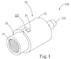
FIG. 1 is a perspective view showing a pneumatic valve adaptor according to a first embodiment of the present invention; -
FIG. 2 is an exploded view ofFIG. 1 ; -
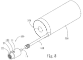
FIG. 3 is perspective view illustrating a first application of the pneumatic valve adaptor according to the present invention; -
FIG. 4 is a cross-sectional view, in an exploded form, illustrating an operation of the first application ofFIG. 3 ; -
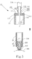
FIG. 5 is a cross-sectional view, similar toFIG. 4 but partly exploded, illustrating a valve coupler of the pneumatic valve adaptor according to the present invention screwed to a pneumatic valve of an inflatable object; -
FIG. 6 is a cross-sectional view, similar toFIG. 5 , illustrating a condition where a fast-releasable gas source connector is rotated to connect with the valve coupler of the pneumatic valve adaptor according to the present invention; -
FIG. 7 is a perspective view showing a pneumatic valve adaptor according to a second embodiment of the present invention; -
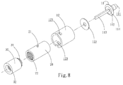
FIG. 8 is an exploded view ofFIG. 7 ; -
FIG. 9 is perspective view illustrating a second application of the pneumatic valve adaptor according to the present invention; -
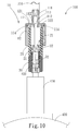
FIG. 10 is a cross-sectional view illustrating a condition where a fast-releasable gas source connector of the pneumatic valve adaptor ofFIG. 9 is rotated to connect with the valve coupler and the valve coupler is screwed to a pneumatic valve of an inflatable object; -
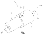
FIG. 11 is a perspective view showing a pneumatic valve adaptor according to a third embodiment of the present invention; -
FIG. 12 is an exploded view ofFIG. 11 ; -
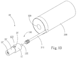
FIG. 13 is perspective view illustrating a third application of the pneumatic valve adaptor according to the present invention; and -
FIG. 14 is a cross-sectional view illustrating a condition where a fast-releasable gas source connector of the pneumatic valve adaptor ofFIG. 13 is rotated to connect with the valve coupler and the valve coupler is screwed to a pneumatic valve of an inflatable object. - Referring to
FIGS. 1 and2 , a pneumatic valve adaptor constructed according to a first embodiment of the present invention is shown, generally designated at 100. Thepneumatic valve adaptor 100 comprises a fast-releasablegas source connector 10. The fast-releasablegas source connector 10 comprises atop source piece 11 and arotatable joint 12. Thetop source piece 11 has a top end that forms a gas inlet opening 111. Thetop source piece 11 has a lower end in which two throughholes 112 and apush pin 113 are formed. The throughholes 112 are in communication with the gas inlet opening 111. Thetop source piece 11 has a lower circumference along which aguide slope surface 114 is formed. - The
rotatable joint 12 has a top end in which a receiving recess 121 (seeFIG. 4 ) is formed. The receivingrecess 121 receives at least oneseal ring 122 disposed therein. The lower end of thetop source piece 11 is tightly fit into thereceiving recess 121 for connection therewith, in such a way that a lower end of thepush pin 113 of thetop source piece 11 extends through thereceiving recess 121 and theseal ring 122 into therotatable joint 12. Therotatable joint 12 has a lower edge in which at least onefirst engagement section 123 is formed. Thefirst engagement section 123 is not limited to any specific form and, in the present invention, an L-shaped fitting slot is taken as an example for achieving bayonet type connection. - At least one
valve coupler 20 has a lateral external surface and a lower end that are respectively provided with at least onesecond engagement section 21 and avalve connection section 22. Thesecond engagement section 21 is not limited to any specific form and, in the present invention, a raised block is taken as an example, where the block of thesecond engagement section 21 and L-shaped slot of thefirst engagement section 123 of the rotatable joint 12 of the fast-releasablegas source connector 10 may engage with/disengage from each other through rotation of the rotatable joint 12 in a clockwise direction or a counterclockwise direction. The rotatable joint 12 may have a rotation stroke that is determined by the size or dimension of thefirst engagement section 123. In the present invention, a short rotation stroke that provides a circumferential movement covering a small circular angle for the raised block is preferred so that the engagement and/or disengagement between thefirst engagement section 123 and thesecond engagement section 21 for coupling and/or separation can be accomplished in a more efficient manner. Thevalve connection section 22 is engageable with and thus connectable to apneumatic valve 210 of an inflatable object 200 (as shown inFIG. 5 ). In a first application of the first embodiment of the present invention, an American valve is taken as an example for the pneumatic valve of the inflatable object and thevalve connection section 22 is structured, in the form of internal threading, to correspond to anexternal thread 220 of thepneumatic valve 210 of theinflatable object 200, which is an American valve in the example, whereby thevalve coupler 20 may be screwed and fixed to thepneumatic valve 210 of theinflatable object 200 by means of thevalve connection section 22. - Referring to
FIGS. 3 ,4 ,5 , and6 , the first application of thepneumatic valve adaptor 100 according to the present invention and an operation thereof are illustrated, wherein the gas inlet opening 111 of thetop source piece 11 of the fast-releasablegas source connector 10 is connectable to asupply tube 310 of a gas source 300 (as shown inFIG. 3 ), and thegas source 300 is allowed to discharge and supply gas through pushing of apush button 320 provided at a top thereof. Thegas source 300 is not limited to any specific form and, in the present invention, a gas-charging type tire sealant that is generally used for repairing a puncture of a tire is taken as an example for illustration. - The
valve connection section 22 of thevalve coupler 20 is then screwed to theexternal thread 220 of thepneumatic valve 210 of theinflatable object 200 that is, in the example, an American valve (as shown inFIG. 5 ). The rotatable joint 12 of the fast-releasablegas source connector 10 is then fit downward to the outside of the valve coupler 20 (as illustrated by the arrow ofFIG. 5 ), in such a way that thefirst engagement section 123 of the rotatable joint 12 and thesecond engagement section 21 of thevalve coupler 20 are first mated to each other, through proper alignment and reception therebetween, and a short stroke of rotation that passes over a small circular angle is applied to the rotatable joint 12 (as illustrated by the arrow ofFIG. 6 ), so that thefirst engagement section 123 and thesecond engagement section 21 are set in mutual engagement with each other and a bottom surface of theseal ring 122 is set in tight contact engagement with a top end of thevalve coupler 20 to cause a circumferential edge of theseal ring 122 that is received in the receivingrecess 121 of the rotatable joint 12 to undergo compression and thus deformation for tight engagement with theguide slope surface 114 on the underside of thetop source piece 11 of the fast-releasable gas source connector 10 (as shown inFIG. 6 ), thereby forming an arrangement of gas-tight engagement. Further, thepush pin 113 that extends to the lower side of thetop source piece 11 of the fast-releasablegas source connector 10 may push down acontact pin 230 arranged in thepneumatic valve 210 of theinflatable object 200, which in the example is an American valve, so as to open thepneumatic valve 210 thereby allowing the gaseous tire sealant supplied from thegas source 300 to flow through thesupply tube 310, the gas inlet opening 111, the throughholes 112, the receivingrecess 121, and theseal ring 122 and get into the interior of thevalve coupler 20 for subsequently feeding through thepneumatic valve 210 into theinflatable object 200, which can be, in the example, a tire. - After the gaseous tire sealant is fed from the
gas source 300 into theinflatable object 200, which in the example is a tire, thepush button 320 of thegas source 300 may be released to cut off the supply of the gaseous tire sealant. An operation carried out in a reversed sequence of the above-described operation with reference toFIGS. 4 ,5 , and6 may be applied to rotate the rotatable joint 12 of the fast-releasablegas source connector 10 in a reversed direction so as to have thefirst engagement section 123 of the rotatable joint 12 and thesecond engagement section 21 of thevalve coupler 20 disengaging from and the separated from each other, allowing the rotatable joint 12 pulled upward for fast detaching thepush pin 113 of thetop source piece 11 of the fast-releasablegas source connector 10 from thecontact pin 230 of thepneumatic valve 210 of theinflatable object 200, whereby thepneumatic valve 210 is closed immediately and no leakage or splashing of the gas or liquid of the tire sealant resulting from incomplete or poor closure of thepneumatic valve 210 may occur. - Referring to
FIGS. 7 ,8 ,9 , and10 , a pneumatic valve adaptor according to a second embodiment of the present invention, also designated at 100, and a second application thereof are illustrated, wherein anextender 30 has a top end and a lower end that are respectively provided with aconnection section 31 and aninternal locking thread 32. Theconnection section 31 is engageable with thevalve connection section 22 of thevalve coupler 20 that are shown in for exampleFIGS. 1-6 . Theconnection section 31 is not limited to any specific form and, in the present invention, an externally threaded hollow pillar is taken as an example, and theinternal locking thread 32 is structured as internal threading corresponding to anexternal thread 420 of apneumatic valve 410 that in the example is a French valve mounted to aninflatable object 400, whereby theextender 30 can be adapted to and connectable with the French valve configuration of thepneumatic valve 410 of theinflatable object 400. With such connection being accomplished as described, a subsequent operation that follows that described with reference toFIGS. 4 ,5 , and6 (in such a sequence) can be taken to have thefirst engagement section 123 of the rotatable joint 12 and thesecond engagement section 21 of thevalve coupler 20 aligned with and mating each other, followed by rotation, either clockwise or counterclockwise, of the rotatable joint 12 to have the rotatable joint 12 and thevalve coupler 20 mounted to the extender 30 (as shown inFIG. 10 ) or detached from each other. In this way, gas or liquid may be fed from thegas source 300, through the French valve configuration of thepneumatic valve 410, into theinflatable object 400 and leakage or splashing of the gas or liquid tire sealant can be prevented. In the second embodiment and the second application, according to thepneumatic valve 210 of theinflatable object 200 that is an American valve or thepneumatic valve 410 of theinflatable object 400 that is a French valve being involved, a user may use thevalve coupler 20 to screw to the American valve configuration of thepneumatic valve 210 or uses anextender 30 to connect with thevalve coupler 20 and then uses theextender 30 to screw to the French valve configuration of thepneumatic valve 410. - Referring to
FIGS. 11 ,12 ,13 , and14 , a pneumatic valve adaptor according to a third embodiment of the present invention, also designated at 100, and a third application thereof are illustrated, wherein the valve connection section 22' of the valve coupler 20' is structured as internal threading corresponding to and engageable with theexternal thread 420 of thepneumatic valve 410 of theinflatable object 400, which is in the form of a French valve, so as to allow for direct screwing and connection of the valve connection section 22' of the valve coupler 20' to the French valve configuration of thepneumatic valve 410 of theinflatable object 400. In the third embodiment and the third application, due to thepneumatic valve 410 of theinflatable object 400 being not necessary to be pushed down by thepush pin 113, the top source piece 11' is provided with no thepush pin 113 at the lower side thereof. An operation, which is carried out following the sequence ofFIGS. 4 ,5 ,6 and described above, may be taken to first have thefirst engagement section 123 of the rotatable joint 12 aligned with and mating the second engagement section 21' of the valve coupler 20', followed by rotation, either clockwise or counterclockwise, of the rotatable joint 12 to have the rotatable joint 12 and the valve coupler 20' connected to each other (as shown inFIG. 14 ) or detached from each other. In this way, gas or liquid may be fed from thegas source 300, through the French valve configuration of thepneumatic valve 410, into theinflatable object 400 and leakage or splashing of the gas or liquid tire sealant can be prevented, similar to what illustrated inFIGS. 1-10 . In the third embodiment and the third application, a user is allowed to fill gaseous or liquid tire sealant into aninflatable object 400 through the French valve configuration of apneumatic valve 410 mounted to theinflatable object 400. - Although the present invention has been described with reference to the preferred embodiments thereof, it is apparent to those skilled in the art that a variety of modifications and changes may be made without departing from the scope of the present invention which is intended to be defined by the appended claims.
Claims (11)
- A pneumatic valve adaptor, comprising: a fast-releasable gas source connector, which comprises:a top source piece and a rotatable joint, the top source piece being connected to a top end of the rotatable joint and adapted to connect with an external fluid source for feeding fluid from the fluid source into the rotatable joint, the rotatable joint having a lower edge in which at least one first engagement section is formed; andat least one valve coupler, which has a lateral external surface and a lower end that are respectively provided with at least one second engagement section and a valve connection section, the second engagement section and the first engagement section corresponding to each other and connectable with and disengageable from each other through rotation of the rotatable joint, the valve connection section adapted to connect with a pneumatic valve of an inflatable object for supplying the fluid from the fluid source into and inflating the inflatable object, the rotatable joint being rotatable in a reversed direction to efficiently separating the fast-releasable gas source connector from the valve coupler.
- The pneumatic valve adaptor as claimed in Claim 1, wherein the top source piece of the fast-releasable gas source connector has a top end that forms a gas inlet opening for connection with a supply tube connector of the fluid source that supplies a tire sealant so as to receive the supply of the fluid of the tire sealant.
- The pneumatic valve adaptor as claimed in Claim 2, wherein the top source piece of the fast-releasable gas source connector has a lower end in which at least two through holes are formed and in communication with the gas inlet opening formed in the top end of the top source piece.
- The pneumatic valve adaptor as claimed in Claim 1, wherein the top source piece of the fast-releasable gas source connector has a lower end to which a push pin is mounted.
- The pneumatic valve adaptor as claimed in Claim 1, wherein the rotatable joint of the fast-releasable gas source connector has a top end in which a receiving recess is formed for receiving a lower end of the top source piece to fit therein and connect therewith.
- The pneumatic valve adaptor as claimed in Claim 1, wherein the rotatable joint of the fast-releasable gas source connector has a top end in which a receiving recess is formed for receiving at least one seal ring to dispose therein.
- The pneumatic valve adaptor as claimed in Claim 1, wherein the top source piece of the fast-releasable gas source connector has a lower circumference along which a guide slope surface is formed.
- The pneumatic valve adaptor as claimed in Claim 1, wherein the first engagement section of the rotatable joint of the fast-releasable gas source connector comprises an L-shaped slot and the second engagement section of the valve coupler comprises a raised block that is receivable in and movable along the L-shaped slot.
- The pneumatic valve adaptor as claimed in Claim 1, wherein the valve connection section of the valve coupler comprises threading corresponding to and engageable with an external thread of an American valve and the pneumatic valve of the inflatable object to which the valve connection section is connectable is an American valve.
- The pneumatic valve adaptor as claimed in Claim 1, wherein the valve connection section of the valve coupler comprises internal threading corresponding to and engageable with an external thread of a French valve and the pneumatic valve of the inflatable object to which the valve connection section is connectable is a French valve.
- The pneumatic valve adaptor as claimed in Claim 1, wherein the valve connection section of the valve coupler comprises an internal thread that corresponds to an external thread of an American valve, the internal thread being connectable with an extender, which comprises an internal locking thread formed therein, the internal locking thread corresponding to and engageable with an external thread of a French valve.
Applications Claiming Priority (1)
| Application Number | Priority Date | Filing Date | Title |
|---|---|---|---|
| TW105103874A TWI596278B (en) | 2016-02-04 | 2016-02-04 | Air nozzle connector |
Publications (1)
| Publication Number | Publication Date |
|---|---|
| EP3202601A1 true EP3202601A1 (en) | 2017-08-09 |
Family
ID=55661193
Family Applications (1)
| Application Number | Title | Priority Date | Filing Date |
|---|---|---|---|
| EP16160842.7A Withdrawn EP3202601A1 (en) | 2016-02-04 | 2016-03-17 | Pneumatic valve adaptor |
Country Status (4)
| Country | Link |
|---|---|
| US (1) | US20170225528A1 (en) |
| EP (1) | EP3202601A1 (en) |
| AU (1) | AU2016201917A1 (en) |
| TW (1) | TWI596278B (en) |
Cited By (3)
| Publication number | Priority date | Publication date | Assignee | Title |
|---|---|---|---|---|
| DE102017102443B3 (en) | 2017-02-08 | 2018-03-01 | Beto Engineering and Marketing Co., Ltd. | Pump head for an American and a French valve |
| EP3719376A4 (en) * | 2017-11-29 | 2021-07-21 | Active Tools International (HK) Ltd. | FASTENING ELEMENT, CONNECTING ARRANGEMENT AND TIRE REPAIR MACHINE |
| CN113996426A (en) * | 2021-10-21 | 2022-02-01 | 山东鑫海矿业技术装备股份有限公司 | Sectional type vortex breaker |
Families Citing this family (9)
| Publication number | Priority date | Publication date | Assignee | Title |
|---|---|---|---|---|
| US10280912B2 (en) * | 2017-01-18 | 2019-05-07 | Beto Engineering & Marketing Co., Ltd. | Air valve connecting device for different inflation valves |
| US10208865B2 (en) * | 2017-01-18 | 2019-02-19 | Beto Engineering & Marketing Co., Ltd. | Air valve connecting device |
| TWI662189B (en) | 2018-07-09 | 2019-06-11 | 僑雄實業股份有限公司 | Mortise pump |
| WO2020218633A1 (en) * | 2019-04-23 | 2020-10-29 | 주식회사 커버써먼 | Air injection apparatus and functional clothing comprising same |
| TWI745753B (en) * | 2019-09-24 | 2021-11-11 | 周文三 | Anti-spray joint structure for gas nozzle of tire of vehicle and connection hose of vehicle air compressor |
| CN111746411A (en) * | 2020-05-26 | 2020-10-09 | 河南高速公路试验检测有限公司 | A multi-function road condition rapid detection vehicle |
| CN112393044B (en) * | 2020-12-02 | 2024-11-19 | 连云港天邦科技开发有限公司 | A quick connector for fluid loading and unloading |
| USD969876S1 (en) | 2020-12-11 | 2022-11-15 | Milwaukee Electric Tool Corporation | Inflator |
| CN117085202B (en) * | 2023-10-09 | 2026-03-13 | 赛乐(常州)医疗科技股份有限公司 | A quick-assembly/disassembly structure and the anesthesia booster device used therein. |
Citations (8)
| Publication number | Priority date | Publication date | Assignee | Title |
|---|---|---|---|---|
| US1442933A (en) * | 1921-04-09 | 1923-01-23 | John P Firpo | Auxiliary valve attachment for tire pumps |
| US1937982A (en) * | 1930-05-29 | 1933-12-05 | Walter H Rudolph | Coupling |
| GB2069083A (en) * | 1980-02-11 | 1981-08-19 | Compair Ind Ltd | Pipe coupling |
| FR2538073A1 (en) * | 1982-12-15 | 1984-06-22 | Hohol Larry | CONNECTION FOR PIPING |
| US7028720B2 (en) | 2000-03-27 | 2006-04-18 | Sumitomo Rubber Industries, Ltd. | Sealing device |
| DE202013101644U1 (en) * | 2012-04-27 | 2013-08-09 | Wen-San Jhou | From a vehicle entrained air compression device |
| CN204095150U (en) | 2014-08-22 | 2015-01-14 | 大捷达实业(深圳)有限公司 | A kind of tire repair liquid container |
| TWM505397U (en) | 2015-03-25 | 2015-07-21 | Beto Engineering & Marketing | Pneumatic tire repair device |
Family Cites Families (6)
| Publication number | Priority date | Publication date | Assignee | Title |
|---|---|---|---|---|
| US6904932B1 (en) * | 2002-10-01 | 2005-06-14 | Trek Bicycle Corporation | Pump valve adapter |
| JP2005335155A (en) * | 2004-05-26 | 2005-12-08 | Bridgestone Corp | Tire sealing device |
| JP2007182036A (en) * | 2006-01-10 | 2007-07-19 | Bridgestone Corp | Connector and connector set |
| JP2008175345A (en) * | 2007-01-22 | 2008-07-31 | Bridgestone Corp | Valve connector |
| JP2011131535A (en) * | 2009-12-25 | 2011-07-07 | Bridgestone Corp | Hose member and sealing/pump-up device |
| TW201317456A (en) * | 2011-10-26 | 2013-05-01 | ying-zhe Huang | Assembled inflation nozzle |
-
2016
- 2016-02-04 TW TW105103874A patent/TWI596278B/en not_active IP Right Cessation
- 2016-03-16 US US15/071,742 patent/US20170225528A1/en not_active Abandoned
- 2016-03-17 EP EP16160842.7A patent/EP3202601A1/en not_active Withdrawn
- 2016-03-29 AU AU2016201917A patent/AU2016201917A1/en not_active Withdrawn
Patent Citations (9)
| Publication number | Priority date | Publication date | Assignee | Title |
|---|---|---|---|---|
| US1442933A (en) * | 1921-04-09 | 1923-01-23 | John P Firpo | Auxiliary valve attachment for tire pumps |
| US1937982A (en) * | 1930-05-29 | 1933-12-05 | Walter H Rudolph | Coupling |
| GB2069083A (en) * | 1980-02-11 | 1981-08-19 | Compair Ind Ltd | Pipe coupling |
| FR2538073A1 (en) * | 1982-12-15 | 1984-06-22 | Hohol Larry | CONNECTION FOR PIPING |
| US7028720B2 (en) | 2000-03-27 | 2006-04-18 | Sumitomo Rubber Industries, Ltd. | Sealing device |
| DE202013101644U1 (en) * | 2012-04-27 | 2013-08-09 | Wen-San Jhou | From a vehicle entrained air compression device |
| TWI490132B (en) | 2012-04-27 | 2015-07-01 | 周文三 | Joint structure of tandem hose for vehicle air compressor |
| CN204095150U (en) | 2014-08-22 | 2015-01-14 | 大捷达实业(深圳)有限公司 | A kind of tire repair liquid container |
| TWM505397U (en) | 2015-03-25 | 2015-07-21 | Beto Engineering & Marketing | Pneumatic tire repair device |
Cited By (4)
| Publication number | Priority date | Publication date | Assignee | Title |
|---|---|---|---|---|
| DE102017102443B3 (en) | 2017-02-08 | 2018-03-01 | Beto Engineering and Marketing Co., Ltd. | Pump head for an American and a French valve |
| EP3719376A4 (en) * | 2017-11-29 | 2021-07-21 | Active Tools International (HK) Ltd. | FASTENING ELEMENT, CONNECTING ARRANGEMENT AND TIRE REPAIR MACHINE |
| US11662046B2 (en) | 2017-11-29 | 2023-05-30 | Active Tools International (Hk) Ltd. | Connection member, connection assembly and tire repair machine |
| CN113996426A (en) * | 2021-10-21 | 2022-02-01 | 山东鑫海矿业技术装备股份有限公司 | Sectional type vortex breaker |
Also Published As
| Publication number | Publication date |
|---|---|
| AU2016201917A1 (en) | 2017-08-24 |
| US20170225528A1 (en) | 2017-08-10 |
| TWI596278B (en) | 2017-08-21 |
| TW201728833A (en) | 2017-08-16 |
Similar Documents
| Publication | Publication Date | Title |
|---|---|---|
| EP3202601A1 (en) | Pneumatic valve adaptor | |
| US5012954A (en) | Tire inflation system | |
| US8627857B2 (en) | Device for sealing and inflating inflatable object | |
| CN102066206B (en) | Structure for preventing dislocation of container, and sealing pump-up device | |
| JP3220429U (en) | Check joint structure of flexible pipe connected in series for air compressor for vehicle | |
| US8978716B2 (en) | Vehicle-carried air compression device | |
| US8402987B2 (en) | Schrader valve/Presta valve dual-mode valve cap | |
| CN103375388B (en) | Joint structure of series connection hose of air compressor for vehicle | |
| EP3797977B1 (en) | Anti-spray joint structure for connection of air nozzle of tire and connection hose of air compressor | |
| CN102405132B (en) | Sealed inflator | |
| KR101830997B1 (en) | Apparatus for the introduction of air and/or sealant into a tire | |
| US8360090B2 (en) | Schrader valve/Presta valve dual-purpose valve cap | |
| US20110041522A1 (en) | Adapter system and method | |
| CN101730619B (en) | Tire sealing device | |
| EP3797978B1 (en) | Anti-spray structure for connection of air nozzle of tire of vehicle and connection hose of air compressor | |
| US11919338B2 (en) | Pneumatic chuck including valve core interface | |
| US8763650B2 (en) | Method and device for recovering puncture repair liquid | |
| US20080257416A1 (en) | Connector with screw valve | |
| TWI783435B (en) | Tool for repairing and inflating tires | |
| CN205395675U (en) | Valve connector | |
| CN221503474U (en) | Portable general air cock of inflating pump | |
| CN107082002A (en) | Air tap joint | |
| CN210211432U (en) | Integrated tire repairing tool | |
| CN110030177B (en) | Inflation connector and combination of inflation connector and gas storage bottle | |
| US20240294042A1 (en) | Tire-repairing connector |
Legal Events
| Date | Code | Title | Description |
|---|---|---|---|
| PUAI | Public reference made under article 153(3) epc to a published international application that has entered the european phase |
Free format text: ORIGINAL CODE: 0009012 |
|
| AK | Designated contracting states |
Kind code of ref document: A1 Designated state(s): AL AT BE BG CH CY CZ DE DK EE ES FI FR GB GR HR HU IE IS IT LI LT LU LV MC MK MT NL NO PL PT RO RS SE SI SK SM TR |
|
| AX | Request for extension of the european patent |
Extension state: BA ME |
|
| STAA | Information on the status of an ep patent application or granted ep patent |
Free format text: STATUS: THE APPLICATION IS DEEMED TO BE WITHDRAWN |
|
| 18D | Application deemed to be withdrawn |
Effective date: 20180210 |