EP3202524A1 - Aligning lasers of laser additive manufacturing system - Google Patents
Aligning lasers of laser additive manufacturing system Download PDFInfo
- Publication number
- EP3202524A1 EP3202524A1 EP17151900.2A EP17151900A EP3202524A1 EP 3202524 A1 EP3202524 A1 EP 3202524A1 EP 17151900 A EP17151900 A EP 17151900A EP 3202524 A1 EP3202524 A1 EP 3202524A1
- Authority
- EP
- European Patent Office
- Prior art keywords
- lasers
- calibrated
- pair
- laser
- test structure
- Prior art date
- Legal status (The legal status is an assumption and is not a legal conclusion. Google has not performed a legal analysis and makes no representation as to the accuracy of the status listed.)
- Granted
Links
Images




Classifications
-
- B—PERFORMING OPERATIONS; TRANSPORTING
- B23—MACHINE TOOLS; METAL-WORKING NOT OTHERWISE PROVIDED FOR
- B23K—SOLDERING OR UNSOLDERING; WELDING; CLADDING OR PLATING BY SOLDERING OR WELDING; CUTTING BY APPLYING HEAT LOCALLY, e.g. FLAME CUTTING; WORKING BY LASER BEAM
- B23K26/00—Working by laser beam, e.g. welding, cutting or boring
- B23K26/12—Working by laser beam, e.g. welding, cutting or boring in a special environment or atmosphere, e.g. in an enclosure
- B23K26/123—Working by laser beam, e.g. welding, cutting or boring in a special environment or atmosphere, e.g. in an enclosure in an atmosphere of particular gases
- B23K26/125—Working by laser beam, e.g. welding, cutting or boring in a special environment or atmosphere, e.g. in an enclosure in an atmosphere of particular gases of mixed gases
-
- B—PERFORMING OPERATIONS; TRANSPORTING
- B23—MACHINE TOOLS; METAL-WORKING NOT OTHERWISE PROVIDED FOR
- B23K—SOLDERING OR UNSOLDERING; WELDING; CLADDING OR PLATING BY SOLDERING OR WELDING; CUTTING BY APPLYING HEAT LOCALLY, e.g. FLAME CUTTING; WORKING BY LASER BEAM
- B23K26/00—Working by laser beam, e.g. welding, cutting or boring
- B23K26/02—Positioning or observing the workpiece, e.g. with respect to the point of impact; Aligning, aiming or focusing the laser beam
- B23K26/035—Aligning the laser beam
-
- B—PERFORMING OPERATIONS; TRANSPORTING
- B22—CASTING; POWDER METALLURGY
- B22F—WORKING METALLIC POWDER; MANUFACTURE OF ARTICLES FROM METALLIC POWDER; MAKING METALLIC POWDER; APPARATUS OR DEVICES SPECIALLY ADAPTED FOR METALLIC POWDER
- B22F10/00—Additive manufacturing of workpieces or articles from metallic powder
- B22F10/30—Process control
- B22F10/31—Calibration of process steps or apparatus settings, e.g. before or during manufacturing
-
- B—PERFORMING OPERATIONS; TRANSPORTING
- B23—MACHINE TOOLS; METAL-WORKING NOT OTHERWISE PROVIDED FOR
- B23K—SOLDERING OR UNSOLDERING; WELDING; CLADDING OR PLATING BY SOLDERING OR WELDING; CUTTING BY APPLYING HEAT LOCALLY, e.g. FLAME CUTTING; WORKING BY LASER BEAM
- B23K26/00—Working by laser beam, e.g. welding, cutting or boring
- B23K26/02—Positioning or observing the workpiece, e.g. with respect to the point of impact; Aligning, aiming or focusing the laser beam
- B23K26/03—Observing, e.g. monitoring, the workpiece
- B23K26/032—Observing, e.g. monitoring, the workpiece using optical means
-
- B—PERFORMING OPERATIONS; TRANSPORTING
- B23—MACHINE TOOLS; METAL-WORKING NOT OTHERWISE PROVIDED FOR
- B23K—SOLDERING OR UNSOLDERING; WELDING; CLADDING OR PLATING BY SOLDERING OR WELDING; CUTTING BY APPLYING HEAT LOCALLY, e.g. FLAME CUTTING; WORKING BY LASER BEAM
- B23K26/00—Working by laser beam, e.g. welding, cutting or boring
- B23K26/02—Positioning or observing the workpiece, e.g. with respect to the point of impact; Aligning, aiming or focusing the laser beam
- B23K26/04—Automatically aligning, aiming or focusing the laser beam, e.g. using the back-scattered light
- B23K26/042—Automatically aligning the laser beam
-
- B—PERFORMING OPERATIONS; TRANSPORTING
- B23—MACHINE TOOLS; METAL-WORKING NOT OTHERWISE PROVIDED FOR
- B23K—SOLDERING OR UNSOLDERING; WELDING; CLADDING OR PLATING BY SOLDERING OR WELDING; CUTTING BY APPLYING HEAT LOCALLY, e.g. FLAME CUTTING; WORKING BY LASER BEAM
- B23K26/00—Working by laser beam, e.g. welding, cutting or boring
- B23K26/02—Positioning or observing the workpiece, e.g. with respect to the point of impact; Aligning, aiming or focusing the laser beam
- B23K26/06—Shaping the laser beam, e.g. by masks or multi-focusing
- B23K26/0604—Shaping the laser beam, e.g. by masks or multi-focusing by a combination of beams
- B23K26/0608—Shaping the laser beam, e.g. by masks or multi-focusing by a combination of beams in the same heat affected zone [HAZ]
-
- B—PERFORMING OPERATIONS; TRANSPORTING
- B23—MACHINE TOOLS; METAL-WORKING NOT OTHERWISE PROVIDED FOR
- B23K—SOLDERING OR UNSOLDERING; WELDING; CLADDING OR PLATING BY SOLDERING OR WELDING; CUTTING BY APPLYING HEAT LOCALLY, e.g. FLAME CUTTING; WORKING BY LASER BEAM
- B23K26/00—Working by laser beam, e.g. welding, cutting or boring
- B23K26/08—Devices involving relative movement between laser beam and workpiece
- B23K26/082—Scanning systems, i.e. devices involving movement of the laser beam relative to the laser head
-
- B—PERFORMING OPERATIONS; TRANSPORTING
- B23—MACHINE TOOLS; METAL-WORKING NOT OTHERWISE PROVIDED FOR
- B23K—SOLDERING OR UNSOLDERING; WELDING; CLADDING OR PLATING BY SOLDERING OR WELDING; CUTTING BY APPLYING HEAT LOCALLY, e.g. FLAME CUTTING; WORKING BY LASER BEAM
- B23K26/00—Working by laser beam, e.g. welding, cutting or boring
- B23K26/12—Working by laser beam, e.g. welding, cutting or boring in a special environment or atmosphere, e.g. in an enclosure
- B23K26/127—Working by laser beam, e.g. welding, cutting or boring in a special environment or atmosphere, e.g. in an enclosure in an enclosure
-
- B—PERFORMING OPERATIONS; TRANSPORTING
- B23—MACHINE TOOLS; METAL-WORKING NOT OTHERWISE PROVIDED FOR
- B23K—SOLDERING OR UNSOLDERING; WELDING; CLADDING OR PLATING BY SOLDERING OR WELDING; CUTTING BY APPLYING HEAT LOCALLY, e.g. FLAME CUTTING; WORKING BY LASER BEAM
- B23K26/00—Working by laser beam, e.g. welding, cutting or boring
- B23K26/34—Laser welding for purposes other than joining
- B23K26/342—Build-up welding
-
- B—PERFORMING OPERATIONS; TRANSPORTING
- B29—WORKING OF PLASTICS; WORKING OF SUBSTANCES IN A PLASTIC STATE IN GENERAL
- B29C—SHAPING OR JOINING OF PLASTICS; SHAPING OF MATERIAL IN A PLASTIC STATE, NOT OTHERWISE PROVIDED FOR; AFTER-TREATMENT OF THE SHAPED PRODUCTS, e.g. REPAIRING
- B29C64/00—Additive manufacturing, i.e. manufacturing of three-dimensional [3D] objects by additive deposition, additive agglomeration or additive layering, e.g. by 3D printing, stereolithography or selective laser sintering
- B29C64/30—Auxiliary operations or equipment
- B29C64/386—Data acquisition or data processing for additive manufacturing
- B29C64/393—Data acquisition or data processing for additive manufacturing for controlling or regulating additive manufacturing processes
-
- B—PERFORMING OPERATIONS; TRANSPORTING
- B22—CASTING; POWDER METALLURGY
- B22F—WORKING METALLIC POWDER; MANUFACTURE OF ARTICLES FROM METALLIC POWDER; MAKING METALLIC POWDER; APPARATUS OR DEVICES SPECIALLY ADAPTED FOR METALLIC POWDER
- B22F10/00—Additive manufacturing of workpieces or articles from metallic powder
- B22F10/20—Direct sintering or melting
- B22F10/28—Powder bed fusion, e.g. selective laser melting [SLM] or electron beam melting [EBM]
-
- B—PERFORMING OPERATIONS; TRANSPORTING
- B22—CASTING; POWDER METALLURGY
- B22F—WORKING METALLIC POWDER; MANUFACTURE OF ARTICLES FROM METALLIC POWDER; MAKING METALLIC POWDER; APPARATUS OR DEVICES SPECIALLY ADAPTED FOR METALLIC POWDER
- B22F10/00—Additive manufacturing of workpieces or articles from metallic powder
- B22F10/30—Process control
- B22F10/32—Process control of the atmosphere, e.g. composition or pressure in a building chamber
-
- B—PERFORMING OPERATIONS; TRANSPORTING
- B22—CASTING; POWDER METALLURGY
- B22F—WORKING METALLIC POWDER; MANUFACTURE OF ARTICLES FROM METALLIC POWDER; MAKING METALLIC POWDER; APPARATUS OR DEVICES SPECIALLY ADAPTED FOR METALLIC POWDER
- B22F2999/00—Aspects linked to processes or compositions used in powder metallurgy
-
- B—PERFORMING OPERATIONS; TRANSPORTING
- B23—MACHINE TOOLS; METAL-WORKING NOT OTHERWISE PROVIDED FOR
- B23K—SOLDERING OR UNSOLDERING; WELDING; CLADDING OR PLATING BY SOLDERING OR WELDING; CUTTING BY APPLYING HEAT LOCALLY, e.g. FLAME CUTTING; WORKING BY LASER BEAM
- B23K2103/00—Materials to be soldered, welded or cut
- B23K2103/18—Dissimilar materials
- B23K2103/26—Alloys of Nickel and Cobalt and Chromium
-
- B—PERFORMING OPERATIONS; TRANSPORTING
- B23—MACHINE TOOLS; METAL-WORKING NOT OTHERWISE PROVIDED FOR
- B23K—SOLDERING OR UNSOLDERING; WELDING; CLADDING OR PLATING BY SOLDERING OR WELDING; CUTTING BY APPLYING HEAT LOCALLY, e.g. FLAME CUTTING; WORKING BY LASER BEAM
- B23K2103/00—Materials to be soldered, welded or cut
- B23K2103/30—Organic materials
- B23K2103/36—Wood or similar materials
-
- B—PERFORMING OPERATIONS; TRANSPORTING
- B33—ADDITIVE MANUFACTURING TECHNOLOGY
- B33Y—ADDITIVE MANUFACTURING, i.e. MANUFACTURING OF THREE-DIMENSIONAL [3D] OBJECTS BY ADDITIVE DEPOSITION, ADDITIVE AGGLOMERATION OR ADDITIVE LAYERING, e.g. BY 3D PRINTING, STEREOLITHOGRAPHY OR SELECTIVE LASER SINTERING
- B33Y10/00—Processes of additive manufacturing
-
- Y—GENERAL TAGGING OF NEW TECHNOLOGICAL DEVELOPMENTS; GENERAL TAGGING OF CROSS-SECTIONAL TECHNOLOGIES SPANNING OVER SEVERAL SECTIONS OF THE IPC; TECHNICAL SUBJECTS COVERED BY FORMER USPC CROSS-REFERENCE ART COLLECTIONS [XRACs] AND DIGESTS
- Y02—TECHNOLOGIES OR APPLICATIONS FOR MITIGATION OR ADAPTATION AGAINST CLIMATE CHANGE
- Y02P—CLIMATE CHANGE MITIGATION TECHNOLOGIES IN THE PRODUCTION OR PROCESSING OF GOODS
- Y02P10/00—Technologies related to metal processing
- Y02P10/25—Process efficiency
Definitions
- the disclosure relates generally to additive manufacturing, and more particularly, to methods for aligning calibrated lasers in a multiple laser, metal additive manufacturing system.
- additive manufacturing includes a wide variety of processes of producing an object through the successive layering of material rather than the removal of material. As such, additive manufacturing can create complex geometries without the use of any sort of tools, molds or fixtures, and with little or no waste material. Instead of machining components from solid billets of material, much of which is cut away and discarded, the only material used in additive manufacturing is what is required to shape the object.
- Additive manufacturing techniques typically include taking a three-dimensional computer aided design (CAD) file of the object to be formed, electronically slicing the object into layers, e.g., 18-102 micrometers thick, and creating a file with a two-dimensional image of each layer. The file may then be loaded into a preparation software system that interprets the file such that the object can be built by different types of additive manufacturing systems.
- CAD computer aided design
- RP rapid prototyping
- DDM direct digital manufacturing
- metal powder additive manufacturing techniques such as selective laser melting (SLM) and direct metal laser melting (DMLM)
- SLM selective laser melting
- DMLM direct metal laser melting
- metal powder layers are sequentially melted together to form the object. More specifically, fine metal powder layers are sequentially melted after being uniformly distributed using an applicator on a metal powder bed.
- the metal powder bed can be moved in a vertical axis.
- the process takes place in a processing chamber having a precisely controlled atmosphere of inert gas, e.g., argon or nitrogen.
- inert gas e.g., argon or nitrogen.
- the laser moves in the X-Y direction using scanning mirrors, and has an intensity sufficient to fully weld (melt) the metal powder to form a solid metal.
- the metal powder bed is lowered for each subsequent two dimensional layer, and the process repeats until the object is completely formed.
- each laser In order to create certain larger objects faster, some metal additive manufacturing systems employ a pair of high powered lasers that work together to form an object.
- each laser is individually calibrated so a known offset correction can be applied for each laser, allowing the precise location of the operational field of each laser to be known.
- each laser has a field 10, 12 upon which it can create a melt pool on the metal powder on a build platform.
- the field indicates the entire area upon with any particular laser can work; the laser works within only a small portion of the field at any given time.
- An overlap region 14 of fields 10, 12 indicates an area in which laser fields 10, 12 intersect or overlap, i.e., both lasers can create a melt pool in that area.
- the lasers In order to create a smooth outer surface, the lasers must be aligned within the overlap region. That is, the lasers cannot just be individually calibrated, but must be aligned so they work together to create an aligned melt pool in the overlap region. As shown in the enlarged, schematic side view of FIG. 2 , layers created by unaligned lasers 16 and 18 create an outer surface 20 of an object 22 in overlap region 14 that is unsmooth or bumpy.
- One approach to identify and correct misaligned lasers employs, as shown in the plan view of FIG. 3 , a fine tuning scan test using a foil 24 in the location of the build platform having a pair of perpendicular gradations 26, 28 with fine tick marks thereon.
- the lasers are applied at low power to each gradation and the amount of X and Y mis-alignment is measured. Any alignment correction(s) required is/are applied to the optics of one of the lasers to make the pair of lasers align.
- This technique however frequently does not correct the mis-alignment sufficiently to create objects with acceptable outer surface smoothness in the overlap region. This technique is inaccurate for a number of reasons.
- the conventional alignment test applies the lasers at low power rather than at the typically higher, operational power that the lasers will be used.
- the conventional alignment test occurs in a two-dimensional space without consideration of the three-dimensional nature of the actual melt pool.
- the conventional alignment test employs the relatively imprecise tick marks of the pair of perpendicular gradations, making an accurate alignment correction very difficult to obtain.
- the conventional alignment test also does not take into consideration the material that will be used to create the object, and its impact on the melt pool.
- conventional laser additive manufacturing systems may also apply an alignment correction randomization in their control software, but this approach is typically ineffective because it only masks the misalignment as opposed to actually correcting for it.
- Alignment correction randomization works within the laser overlap region (region where multiple lasers can work on the same part on any given layer) by randomizing where each laser starts and stops within the overlapping area preventing the visualization of a single discrete starting and stopping point for each laser along the vertical (Z) axis of the part.
- a first aspect of the disclosure provides a method for aligning a pair of calibrated lasers of a laser additive manufacturing system in an overlap region in which the pair of calibrated lasers selectively operate, the method comprising: first forming a first plurality of layers of a test structure in the overlap region of the pair of calibrated lasers solely using a first calibrated laser of the pair of calibrated lasers; second forming a second plurality of layers of the test structure in the overlap region of the pair of calibrated lasers solely using a second calibrated laser of the pair of calibrated lasers, the first and second forming creating an outer surface of the test structure corresponding to the overlap region; measuring a dimension of an offset step created between the first plurality of layers and the second plurality of lasers in the outer surface of the test structure; and aligning the pair of calibrated lasers by applying the dimension of the offset step as an alignment correction to at least one of the pair of calibrated lasers.
- a second aspect of the disclosure provides a method for aligning a pair of calibrated lasers of a laser additive manufacturing system in an overlap region in which the pair of calibrated lasers selectively operate, the method comprising: first forming a first plurality of layers of a test structure in the overlap region of the pair of calibrated lasers solely using a first calibrated laser of the pair of calibrated lasers; second forming a second plurality of layers of the test structure in the overlap region of the pair of calibrated lasers solely using a second calibrated laser of the pair of calibrated lasers, the first and second forming creating an outer surface of the test structure corresponding to the overlap region, wherein the first and second forming include employing a laser power for each of the first and second calibrated lasers substantially equal to a laser power at which each calibrated laser operates to create an object using the laser additive manufacturing system; measuring a dimension of an offset step created between the first plurality of layers and the second plurality of lasers in the outer surface of the test structure; and aligning the pair of calibrated lasers
- a third aspect of the disclosure provides a method for aligning a pair of calibrated lasers of a laser additive manufacturing system in an overlap region in which the pair of calibrated lasers selectively operate, the method comprising: first forming a first plurality of layers of a test structure in the overlap region of the pair of calibrated lasers solely using a first calibrated laser of the pair of calibrated lasers; second forming a second plurality of layers of the test structure in the overlap region of the pair of calibrated lasers solely using a second calibrated laser of the pair of calibrated lasers, the first and second forming creating an outer surface of the test structure corresponding to the overlap region, wherein the first and second forming include employing a laser power for each of the first and second calibrated lasers substantially equal to a laser power at which each calibrated laser operates to create an object using the laser additive manufacturing system; measuring an X-direction dimension of an X-direction offset step created between the first plurality of layers and the second plurality of lasers in the outer surface of the test structure; measuring
- the disclosure provides methods for aligning lasers of a laser, metal powder additive manufacturing system.
- the method generates a test structure at or near full operational power of the lasers and in three-dimensions, thus making the test structure more accurately representative of an actual melt pool created by the lasers.
- the test structure is formed in the overlap region of the two lasers and includes two pluralities/groups of layers, each formed exclusively by one of the lasers. Since each laser forms a respective plurality of layers of the test structure, a dimension of an offset step in the X-direction and/or the Y-direction between the two plurality of layers indicates an amount of misalignment.
- the dimension(s) of the offset step(s) can be measured to accurately determine the misalignment, and the dimension(s) of the offset step(s) can be applied to the system as an alignment correction(s) to align the lasers.
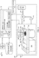
- FIG. 4 shows a schematic/block view of an illustrative computerized laser, metal powder additive manufacturing system 100 for generating an object 102, of which only an upper surface is shown.
- system 100 is arranged for direct metal laser melting (DMLM).
- DMLM direct metal laser melting
- SLM selective laser melting
- Object 102 is illustrated as a circular element; however, it is understood that the additive manufacturing process can be readily adapted to manufacture a large variety of parts.
- System 100 generally includes a laser, metal powder additive manufacturing control system 104 ("control system") and an AM printer 106.
- control system 104 executes code 108 to generate object 102 using multiple lasers 134, 136.
- Control system 104 is shown implemented on computer 110 as computer program code.
- computer 110 is shown including a memory 112, a processor 114, an input/output (I/O) interface 116, and a bus 118. Further, computer 110 is shown in communication with an external I/O device/resource 120 and a storage system 122.
- processor 114 executes computer program code 108 that is stored in memory 112 and/or storage system 112.
- processor 114 While executing computer program code 108, processor 114 can read and/or write data to/from memory 112, storage system 122, I/O device 120 and/or AM printer 106.
- Bus 118 provides a communication link between each of the components in computer 110, and I/O device 120 can comprise any device that enables a user to interact with computer 110 (e.g., keyboard, pointing device, display, etc.).
- Computer 110 is only representative of various possible combinations of hardware and software.
- processor 114 may comprise a single processing unit, or be distributed across one or more processing units in one or more locations, e.g., on a client and server.
- memory 112 and/or storage system 122 may reside at one or more physical locations.
- Memory 112 and/or storage system 122 can comprise any combination of various types of non-transitory computer readable storage medium including magnetic media, optical media, random access memory (RAM), read only memory (ROM), etc.
- Computer 110 can comprise any type of computing device such as an industrial controller, a network server, a desktop computer, a laptop, a handheld device, etc.
- Code 108 can include, inter alia, a set of computer-executable instructions 108S for operating AM printer 106, and a set of computer-executable instructions 1080 defining object 102 to be physically generated by AM printer 106.
- a non-transitory computer readable storage medium e.g., memory 112, storage system 122, etc.
- Set of computer-executable instructions 108S for operating AM printer 106 may include any now known or later developed software code capable of operating AM printer 106.
- set of computer-executable instructions 108S may employ one or more alignment correction(s) 111, capable of correcting a position of lasers 134, 136 in an X and/or Y direction (see FIG. 6 ) to ensure alignment between lasers 134, 136.
- alignment correction(s) 111 capable of correcting a position of lasers 134, 136 in an X and/or Y direction (see FIG. 6 ) to ensure alignment between lasers 134, 136.
- Set of computer-executable instructions 1080 defining object 102 may include a precisely defined 3D model of an object and can be generated from any of a large variety of well-known computer aided design (CAD) software systems such as AutoCAD®, TurboCAD®, DesignCAD 3D Max, etc.
- code 1080 can include any now known or later developed file format.
- code 1080 representative of object 102 may be translated between different formats.
- code 1080 may include Standard Tessellation Language (STL) files which was created for stereolithography CAD programs of 3D Systems, or an additive manufacturing file (AMF), which is an American Society of Mechanical Engineers (ASME) standard that is an extensible markup-language (XML) based format designed to allow any CAD software to describe the shape and composition of any three-dimensional object to be fabricated on any AM printer.
- Code 1080 representative of object 102 may also be converted into a set of data signals and transmitted, received as a set of data signals and converted to code, stored, etc., as necessary.
- code 1080 may be an input to system 100 and may come from a part designer, an intellectual property (IP) provider, a design company, the operator or owner of system 100, or from other sources.
- control system 104 executes code 108S and 1080, dividing object 102 into a series of thin slices that it assembles using AM printer 106 in successive layers of material.
- AM printer 106 may include a processing chamber 130 that is sealed to provide a controlled atmosphere for object 102 printing.
- a metal powder bed or platform 132 upon which object 102 is built, is positioned within processing chamber 130.
- a number of lasers 134, 136 are configured to melt layers of metal powder on metal powder bed 132 to generate object 102. While a pair of lasers 134, 136 will be described herein, it is emphasized that the teachings of the disclosure are applicable to a system employing more than a pair of lasers 134, 136.
- Each laser 134, 136 as described relative to FIG. 1 , has a field in which it can melt metal powder alone and an overlap region in which both lasers 134, 136 can melt metal powder.
- each laser 134, 136 may generate a laser beams 138, 138', respectively, that fuses particles for each slice, as defined by code 108.
- Laser 134 is shown creating a layer of object 102 using laser beam 138, while laser 136 is shown dormant but with a phantom laser beam 138'.
- Each laser 134, 136 is calibrated in any now known or later developed manner. That is, each laser 134, 136 has had its laser beam's anticipated position relative to platform 132 correlated with its actual position in order to provide an individual position correction (not shown) to ensure its individual accuracy.
- An applicator 140 may create a thin layer of raw material 142 spread out as the blank canvas from which each successive slice of the final object will be created.
- Various parts of AM printer 106 may move to accommodate the addition of each new layer, e.g., a metal powder bed 132 may lower and/or chamber 130 and/or applicator 140 may rise after each layer.
- the process may use different raw materials in the form of fine-grain metal powder, a stock of which may be held in a chamber 144 accessible by applicator 140.
- object 102 may be made of a "metal" which may include a pure metal or an alloy.
- the metal may include practically any non-reactive metal powder, i.e., non-explosive or non-conductive powder, such as but not limited to: a cobalt chromium molybdenum (CoCrMo) alloy, stainless steel, an austenite nickel-chromium based alloy such as a nickel-chromium-molybdenum-niobium alloy (NiCrMoNb) (e.g., Inconel 625 or Inconel 718), a nickel-chromium-iron-molybdenum alloy (NiCrFeMo) (e.g., Hastelloy® X available from Haynes International, Inc.), or a nickel-chromium-cobalt-molybdenum alloy (NiCrCoMo) (e.g., Haynes 282 available from Haynes International, Inc.), etc.
- a cobalt chromium molybdenum (CoCrMo) alloy such as a nickel-chromium
- Processing chamber 130 is filled with an inert gas such as argon or nitrogen and controlled to minimize or eliminate oxygen.
- Control system 104 is configured to control a flow of a gas mixture 160 within processing chamber 130 from a source of inert gas 154.
- control system 104 may control a pump 150, and/or a flow valve system 152 for inert gas to control the content of gas mixture 160.
- Flow valve system 152 may include one or more computer controllable valves, flow sensors, temperature sensors, pressure sensors, etc., capable of precisely controlling flow of the particular gas.
- Pump 150 may be provided with our without valve system 152. Where pump 150 is omitted, inert gas may simply enter a conduit or manifold prior to introduction to processing chamber 130.
- Source of inert gas 154 may take the form of any conventional source for the material contained therein, e.g. a tank, reservoir or other source. Any sensors (not shown) required to measure gas mixture 160 may be provided. Gas mixture 160 may be filtered using a filter 170 in a conventional manner.
- metal powder bed 132 is provided within processing chamber 130, and control system 104 controls flow of gas mixture 160 within processing chamber 130 from source of inert gas 154. Control system 104 also controls AM printer 106, and in particular, applicator 140 and lasers 134, 136 to sequentially melt layers of metal powder on metal powder bed 132 to generate object 102.
- object 102 is formed as a test structure 180 exclusively within overlap region 182 such that test structure 180 can be used to determine misalignment of calibrated lasers 134, 136.
- Test structure 180 can be made of any of the afore-mentioned materials and is ideally formed with operational parameters substantially equivalent to normal object 102 formation.
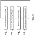
- embodiments of the method may include, S10, forming a first plurality of layers 184 of (partially completed) test structure 180 in overlap region 182 of pair of calibrated lasers 134, 136 solely using a first calibrated laser 134 of pair of calibrated lasers 134, 136.
- a second calibrated laser 136 is dormant during this process.
- Laser beam 138 of calibrated laser 134 and an anticipated overlap region 182 are shown in phantom in FIG. 6 .
- calibrated laser 134 is operated employing a laser power substantially equal to a laser power at which calibrated laser 134 operates to create object 102 using the laser additive manufacturing system 100.
- calibrated laser 134 and the rest of AM printer 106 are operated at as close to normal operating conditions as possible for the material and/or object for which alignment of calibrated lasers 134, 136 is sought.
- a second plurality of layers 190 of test structure 180 are formed in overlap region 182 (now hidden in FIG. 7 , see FIG. 6 ) of pair of calibrated lasers 134, 136 solely using a second calibrated laser 136 of pair of calibrated lasers 134, 136. That is, second plurality of layers 190 are formed atop first plurality of layers 184 to form test structure 180.
- First calibrated laser 134 is dormant during this process.
- the forming steps, S10 and S12 create an outer surface 192 of test structure 180 corresponding to overlap region 182 ( FIG. 6 ).
- Laser beam 138' of calibrated laser 136 is shown in phantom in FIG.
- Second calibrated laser 136 is operated employing a laser power substantially equal to a laser power at which calibrated laser 136 operates to create object 102 using the laser additive manufacturing system 100. That is, second calibrated laser 136 is operated at the same conditions as first calibrated laser 134 during forming of plurality of layers 184. As noted, the actual laser power employed may vary depending on a number of factors.
- the forming steps may include forming test structure 180 on a member 198 that is removable from laser additive manufacturing system 100.
- Member 198 may include any structure capable of providing a foundation for test structure 180, e.g., a metal plate.
- a dimension (Dx and/or Dy) of an offset step 200 and/or 202 created between first plurality of layers 184 and second plurality of layers 190 in outer surface 192 of test structure 180 is/are measured.
- calibrated lasers 134, 136 may be misaligned in the X-direction and the Y-direction. It is emphasized, however, that calibrated lasers 134, 136 may be misaligned in only one direction, X or Y, or may be aligned.
- the measuring may be conducted using any now known or later developed measurement system 210.
- measurement system 210 may include a coordinate measuring machine to scan outer surface 192 of test structure 180.
- the coordinate measuring machine may include a laser configured to scan outer surface 192 of test structure 180 to obtain the dimension(s). While FIG. 8 shows a scan as if a light source, measurement system 210 could employ any measurement technique including mechanical probes, etc.
- the dimension(s) Dx, Dy may be measured in any desired units, e.g., micrometers, millimeters, etc.
- measurement system 210 may measure an X-direction dimension Dx of an X-direction offset step 200 created between first plurality of layers 184 and second plurality of lasers 190 in outer surface 192 of test structure 180. And, measurement system 210 may measure a Y-direction dimension Dy of an Y-direction offset step 202 created between first plurality of layers 184 and second plurality of layers 190 in outer surface 192 of test structure 180. Alternatively, where the misalignment direction is known or only one misalignment direction is of concern, measurement system 210 may simply measure one dimension Dx or Dy.
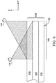
- pair of calibrated lasers 134, 136 are aligned by applying the dimension (Dx and/or Dy) of the offset step as an alignment correction 111 ( FIG. 4 ) to at least one of pair of calibrated lasers 134, 136.
- Alignment correction(s) 111 would be employed in a conventional fashion by control system 104 to control AM printer 106 and, in particular, calibrated lasers 134, 136.
- an X-direction misalignment (Dx) of 0.1 millimeters would be used to adjust calibrated laser(s) 134, 136 0.1 mm in the X-direction in such a way to remove the misalignment. In this fashion, as shown in FIG.
- both calibrated lasers 134, 136 may be adjusted using alignment correction(s) 111; however, ideally, only a selected one of pair of calibrated lasers 134, 136 is adjusted. It is emphasized that one or more alignment corrections 111 aligning the pair of calibrated lasers may be provided. For example, in terms of 2 corrections being applied, X-direction dimension Dx of X-direction offset step 200 may be applied as a first alignment correction 111 ( FIG.
- Y-direction dimension Dy of Y-direction offset step 202 may be applied as a second alignment correction 111 ( FIG. 4 ) to the same selected one of pair of calibrated lasers 134, 136 for the same overlap region 182.
- each overlap region 182 may exist, i.e., across metal powder bed 142 ( FIG. 4 ).
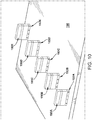
- steps S10-16 may be repeated for each of a plurality of test structures 180A-E (five shown, but could be more or less) corresponding to a plurality of overlap regions 182A-E (under test structures 180A-E, respectively) of laser additive manufacturing system 100. That is, each overlap region 182A-E may have a corresponding alignment correction(s) 111 ( FIG. 4 ), e.g., X-direction and/or Y-direction.
- a standard deviation of less than a predetermined threshold e.g., 30 micrometers, across test structures 180A-E is sought to ensure accuracy for all objects created using system 100. If a standard deviation within the predetermined threshold cannot be obtained, it is an indication to a user that other calibration processes, other than alignment, may be required.
- This methods of the disclosure provide techniques for isolating multiple calibrated lasers in laser additive manufacturing system 100 for measuring the relative X and Y direction misalignment from each other so that the multiple lasers can be used to seamlessly build a single large object without any indications of multiple lasers being present. Consequently, the disclosure allows for building larger more complex laser based additive objects, e.g., using two or more lasers. While the teachings of the disclosure have been applied to a pair of calibrated lasers 134, 136, it is emphasized that the teachings can be extended to systems employing more than two lasers.
- first and second forming include forming the test structure on a member removable from the laser additive manufacturing system.
Landscapes
- Engineering & Computer Science (AREA)
- Physics & Mathematics (AREA)
- Optics & Photonics (AREA)
- Mechanical Engineering (AREA)
- Plasma & Fusion (AREA)
- Chemical & Material Sciences (AREA)
- Materials Engineering (AREA)
- Manufacturing & Machinery (AREA)
- Automation & Control Theory (AREA)
- Powder Metallurgy (AREA)
- Laser Beam Processing (AREA)
- Length Measuring Devices By Optical Means (AREA)
Abstract
Description
- The disclosure relates generally to additive manufacturing, and more particularly, to methods for aligning calibrated lasers in a multiple laser, metal additive manufacturing system.
- Additive manufacturing (AM) includes a wide variety of processes of producing an object through the successive layering of material rather than the removal of material. As such, additive manufacturing can create complex geometries without the use of any sort of tools, molds or fixtures, and with little or no waste material. Instead of machining components from solid billets of material, much of which is cut away and discarded, the only material used in additive manufacturing is what is required to shape the object.
- Additive manufacturing techniques typically include taking a three-dimensional computer aided design (CAD) file of the object to be formed, electronically slicing the object into layers, e.g., 18-102 micrometers thick, and creating a file with a two-dimensional image of each layer. The file may then be loaded into a preparation software system that interprets the file such that the object can be built by different types of additive manufacturing systems. In 3D printing, rapid prototyping (RP), and direct digital manufacturing (DDM) forms of additive manufacturing, material layers are selectively dispensed to create the object.
- In metal powder additive manufacturing techniques, such as selective laser melting (SLM) and direct metal laser melting (DMLM), metal powder layers are sequentially melted together to form the object. More specifically, fine metal powder layers are sequentially melted after being uniformly distributed using an applicator on a metal powder bed. The metal powder bed can be moved in a vertical axis. The process takes place in a processing chamber having a precisely controlled atmosphere of inert gas, e.g., argon or nitrogen. Once each layer is created, each two dimensional slice of the object geometry can be fused by selectively melting the metal powder. The melting may be performed by a high powered laser such as a 100 Watt ytterbium laser to fully weld (melt) the metal powder to form a solid metal. The laser moves in the X-Y direction using scanning mirrors, and has an intensity sufficient to fully weld (melt) the metal powder to form a solid metal. The metal powder bed is lowered for each subsequent two dimensional layer, and the process repeats until the object is completely formed.
- In order to create certain larger objects faster, some metal additive manufacturing systems employ a pair of high powered lasers that work together to form an object. Typically, each laser is individually calibrated so a known offset correction can be applied for each laser, allowing the precise location of the operational field of each laser to be known. In these type machines, as shown in the schematic plan view of
FIG. 1 , each laser has afield overlap region 14 offields laser fields FIG. 2 , layers created byunaligned lasers outer surface 20 of anobject 22 inoverlap region 14 that is unsmooth or bumpy. - One approach to identify and correct misaligned lasers employs, as shown in the plan view of
FIG. 3 , a fine tuning scan test using afoil 24 in the location of the build platform having a pair ofperpendicular gradations - A first aspect of the disclosure provides a method for aligning a pair of calibrated lasers of a laser additive manufacturing system in an overlap region in which the pair of calibrated lasers selectively operate, the method comprising: first forming a first plurality of layers of a test structure in the overlap region of the pair of calibrated lasers solely using a first calibrated laser of the pair of calibrated lasers; second forming a second plurality of layers of the test structure in the overlap region of the pair of calibrated lasers solely using a second calibrated laser of the pair of calibrated lasers, the first and second forming creating an outer surface of the test structure corresponding to the overlap region; measuring a dimension of an offset step created between the first plurality of layers and the second plurality of lasers in the outer surface of the test structure; and aligning the pair of calibrated lasers by applying the dimension of the offset step as an alignment correction to at least one of the pair of calibrated lasers.
- A second aspect of the disclosure provides a method for aligning a pair of calibrated lasers of a laser additive manufacturing system in an overlap region in which the pair of calibrated lasers selectively operate, the method comprising: first forming a first plurality of layers of a test structure in the overlap region of the pair of calibrated lasers solely using a first calibrated laser of the pair of calibrated lasers; second forming a second plurality of layers of the test structure in the overlap region of the pair of calibrated lasers solely using a second calibrated laser of the pair of calibrated lasers, the first and second forming creating an outer surface of the test structure corresponding to the overlap region, wherein the first and second forming include employing a laser power for each of the first and second calibrated lasers substantially equal to a laser power at which each calibrated laser operates to create an object using the laser additive manufacturing system; measuring a dimension of an offset step created between the first plurality of layers and the second plurality of lasers in the outer surface of the test structure; and aligning the pair of calibrated lasers by applying the dimension of the offset step as an alignment correction to a selected one of the pair of calibrated lasers.
- A third aspect of the disclosure provides a method for aligning a pair of calibrated lasers of a laser additive manufacturing system in an overlap region in which the pair of calibrated lasers selectively operate, the method comprising: first forming a first plurality of layers of a test structure in the overlap region of the pair of calibrated lasers solely using a first calibrated laser of the pair of calibrated lasers; second forming a second plurality of layers of the test structure in the overlap region of the pair of calibrated lasers solely using a second calibrated laser of the pair of calibrated lasers, the first and second forming creating an outer surface of the test structure corresponding to the overlap region, wherein the first and second forming include employing a laser power for each of the first and second calibrated lasers substantially equal to a laser power at which each calibrated laser operates to create an object using the laser additive manufacturing system; measuring an X-direction dimension of an X-direction offset step created between the first plurality of layers and the second plurality of lasers in the outer surface of the test structure; measuring a Y-direction dimension of an Y-direction offset step created between the first plurality of layers and the second plurality of lasers in the outer surface of the test structure; and aligning the pair of calibrated lasers by applying the X-direction dimension of the X-direction offset step as a first alignment correction to a selected one of the pair of calibrated lasers and applying the Y-direction dimension of the Y-direction offset step as a second alignment correction to the selected one of the pair of calibrated lasers.
- The illustrative aspects of the present disclosure are designed to solve the problems herein described and/or other problems not discussed.
- These and other features of this disclosure will be more readily understood from the following detailed description of the various aspects of the disclosure taken in conjunction with the accompanying drawings that depict various embodiments of the disclosure, in which:
-
FIG. 1 shows a schematic plan view of fields of a pair of lasers from a laser additive manufacturing system and an overlap region thereof. -
FIG. 2 shows an enlarged, schematic side view of layers of an object formed by a pair of unaligned lasers. -
FIG. 3 shows a plan view of an alignment test foil used for a conventional alignment test for a pair of lasers. -
FIG. 4 shows a block diagram of an illustrative laser additive manufacturing system to which alignment correction(s) created according to embodiments of the disclosure can be applied. -
FIG. 5 shows a flow diagram of methods according to embodiments of the disclosure. -
FIGS. 6-8 show perspective views of a test structure formed according to embodiments of methods of the disclosure. -
FIG. 9 shows an enlarged, schematic side view of layers of an object formed by a pair of lasers aligned according to embodiments of the disclosure. -
FIG. 10 shows a perspective view of a plurality of test structures formed according to embodiments of methods of the disclosure. - It is noted that the drawings of the disclosure are not to scale. The drawings are intended to depict only typical aspects of the disclosure, and therefore should not be considered as limiting the scope of the disclosure. In the drawings, like numbering represents like elements between the drawings.
- As indicated above, the disclosure provides methods for aligning lasers of a laser, metal powder additive manufacturing system. The method generates a test structure at or near full operational power of the lasers and in three-dimensions, thus making the test structure more accurately representative of an actual melt pool created by the lasers. The test structure is formed in the overlap region of the two lasers and includes two pluralities/groups of layers, each formed exclusively by one of the lasers. Since each laser forms a respective plurality of layers of the test structure, a dimension of an offset step in the X-direction and/or the Y-direction between the two plurality of layers indicates an amount of misalignment. The dimension(s) of the offset step(s) can be measured to accurately determine the misalignment, and the dimension(s) of the offset step(s) can be applied to the system as an alignment correction(s) to align the lasers.
-
FIG. 4 shows a schematic/block view of an illustrative computerized laser, metal powderadditive manufacturing system 100 for generating anobject 102, of which only an upper surface is shown. In this example,system 100 is arranged for direct metal laser melting (DMLM). It is understood that the general teachings of the disclosure are equally applicable to other forms of metal powder laser additive manufacturing such as selective laser melting (SLM).Object 102 is illustrated as a circular element; however, it is understood that the additive manufacturing process can be readily adapted to manufacture a large variety of parts. -
System 100 generally includes a laser, metal powder additive manufacturing control system 104 ("control system") and anAM printer 106. As will be described,control system 104 executescode 108 to generateobject 102 usingmultiple lasers Control system 104 is shown implemented oncomputer 110 as computer program code. To this extent,computer 110 is shown including amemory 112, aprocessor 114, an input/output (I/O)interface 116, and abus 118. Further,computer 110 is shown in communication with an external I/O device/resource 120 and astorage system 122. In general,processor 114 executescomputer program code 108 that is stored inmemory 112 and/orstorage system 112. While executingcomputer program code 108,processor 114 can read and/or write data to/frommemory 112,storage system 122, I/O device 120 and/orAM printer 106.Bus 118 provides a communication link between each of the components incomputer 110, and I/O device 120 can comprise any device that enables a user to interact with computer 110 (e.g., keyboard, pointing device, display, etc.).Computer 110 is only representative of various possible combinations of hardware and software. For example,processor 114 may comprise a single processing unit, or be distributed across one or more processing units in one or more locations, e.g., on a client and server. Similarly,memory 112 and/orstorage system 122 may reside at one or more physical locations.Memory 112 and/orstorage system 122 can comprise any combination of various types of non-transitory computer readable storage medium including magnetic media, optical media, random access memory (RAM), read only memory (ROM), etc.Computer 110 can comprise any type of computing device such as an industrial controller, a network server, a desktop computer, a laptop, a handheld device, etc. - As noted,
system 100 and inparticular control system 104 executescode 108 to generateobject 102.Code 108 can include, inter alia, a set of computer-executable instructions 108S for operatingAM printer 106, and a set of computer-executable instructions 1080 definingobject 102 to be physically generated byAM printer 106. As described herein, additive manufacturing processes begin with a non-transitory computer readable storage medium (e.g.,memory 112,storage system 122, etc.) storingcode 108. Set of computer-executable instructions 108S for operatingAM printer 106 may include any now known or later developed software code capable of operatingAM printer 106. In addition, set of computer-executable instructions 108S may employ one or more alignment correction(s) 111, capable of correcting a position oflasers FIG. 6 ) to ensure alignment betweenlasers - Set of computer-
executable instructions 1080 definingobject 102 may include a precisely defined 3D model of an object and can be generated from any of a large variety of well-known computer aided design (CAD) software systems such as AutoCAD®, TurboCAD®, DesignCAD 3D Max, etc. In this regard,code 1080 can include any now known or later developed file format. Furthermore,code 1080 representative ofobject 102 may be translated between different formats. For example,code 1080 may include Standard Tessellation Language (STL) files which was created for stereolithography CAD programs of 3D Systems, or an additive manufacturing file (AMF), which is an American Society of Mechanical Engineers (ASME) standard that is an extensible markup-language (XML) based format designed to allow any CAD software to describe the shape and composition of any three-dimensional object to be fabricated on any AM printer.Code 1080 representative ofobject 102 may also be converted into a set of data signals and transmitted, received as a set of data signals and converted to code, stored, etc., as necessary. In any event,code 1080 may be an input tosystem 100 and may come from a part designer, an intellectual property (IP) provider, a design company, the operator or owner ofsystem 100, or from other sources. In any event,control system 104 executescode object 102 into a series of thin slices that it assembles usingAM printer 106 in successive layers of material. -
AM printer 106 may include aprocessing chamber 130 that is sealed to provide a controlled atmosphere forobject 102 printing. A metal powder bed orplatform 132, upon which object 102 is built, is positioned withinprocessing chamber 130. A number oflasers metal powder bed 132 to generateobject 102. While a pair oflasers lasers laser FIG. 1 , has a field in which it can melt metal powder alone and an overlap region in which bothlasers laser laser beams 138, 138', respectively, that fuses particles for each slice, as defined bycode 108.Laser 134 is shown creating a layer ofobject 102 usinglaser beam 138, whilelaser 136 is shown dormant but with a phantom laser beam 138'. Eachlaser laser platform 132 correlated with its actual position in order to provide an individual position correction (not shown) to ensure its individual accuracy. - An
applicator 140 may create a thin layer ofraw material 142 spread out as the blank canvas from which each successive slice of the final object will be created. Various parts ofAM printer 106 may move to accommodate the addition of each new layer, e.g., ametal powder bed 132 may lower and/orchamber 130 and/orapplicator 140 may rise after each layer. The process may use different raw materials in the form of fine-grain metal powder, a stock of which may be held in achamber 144 accessible byapplicator 140. In the instant case, object 102 may be made of a "metal" which may include a pure metal or an alloy. In one example, the metal may include practically any non-reactive metal powder, i.e., non-explosive or non-conductive powder, such as but not limited to: a cobalt chromium molybdenum (CoCrMo) alloy, stainless steel, an austenite nickel-chromium based alloy such as a nickel-chromium-molybdenum-niobium alloy (NiCrMoNb) (e.g., Inconel 625 or Inconel 718), a nickel-chromium-iron-molybdenum alloy (NiCrFeMo) (e.g., Hastelloy® X available from Haynes International, Inc.), or a nickel-chromium-cobalt-molybdenum alloy (NiCrCoMo) (e.g., Haynes 282 available from Haynes International, Inc.), etc. -
Processing chamber 130 is filled with an inert gas such as argon or nitrogen and controlled to minimize or eliminate oxygen.Control system 104 is configured to control a flow of agas mixture 160 withinprocessing chamber 130 from a source ofinert gas 154. In this case,control system 104 may control apump 150, and/or aflow valve system 152 for inert gas to control the content ofgas mixture 160.Flow valve system 152 may include one or more computer controllable valves, flow sensors, temperature sensors, pressure sensors, etc., capable of precisely controlling flow of the particular gas. Pump 150 may be provided with our withoutvalve system 152. Where pump 150 is omitted, inert gas may simply enter a conduit or manifold prior to introduction toprocessing chamber 130. Source ofinert gas 154 may take the form of any conventional source for the material contained therein, e.g. a tank, reservoir or other source. Any sensors (not shown) required to measuregas mixture 160 may be provided.Gas mixture 160 may be filtered using afilter 170 in a conventional manner. - In operation,
metal powder bed 132 is provided withinprocessing chamber 130, andcontrol system 104 controls flow ofgas mixture 160 withinprocessing chamber 130 from source ofinert gas 154.Control system 104 also controlsAM printer 106, and in particular,applicator 140 andlasers metal powder bed 132 to generateobject 102. - Referring to
FIGS. 5-10 , embodiments of a method for aligning pair of calibratedlasers additive manufacturing system 100 in an overlap region 182 (FIG. 6 ) in which the pair of calibrated lasers selectively operate, will now be described. According to embodiments of the disclosure,object 102 is formed as atest structure 180 exclusively withinoverlap region 182 such thattest structure 180 can be used to determine misalignment of calibratedlasers Test structure 180 can be made of any of the afore-mentioned materials and is ideally formed with operational parameters substantially equivalent tonormal object 102 formation. - With first reference to the flow diagram of
FIG. 5 in conjunction with the perspective view ofFIG. 6 , embodiments of the method may include, S10, forming a first plurality oflayers 184 of (partially completed)test structure 180 inoverlap region 182 of pair of calibratedlasers laser 134 of pair of calibratedlasers laser 136 is dormant during this process.Laser beam 138 of calibratedlaser 134 and ananticipated overlap region 182 are shown in phantom inFIG. 6 . In one embodiment, calibratedlaser 134 is operated employing a laser power substantially equal to a laser power at which calibratedlaser 134 operates to createobject 102 using the laseradditive manufacturing system 100. The actual laser power employed may vary depending on a number of factors such as but not limited to the metal powder used (e.g., Inconel would be different than CoCr) and object 102 being formed. In any event, calibratedlaser 134 and the rest ofAM printer 106 are operated at as close to normal operating conditions as possible for the material and/or object for which alignment of calibratedlasers - Referring to
FIGS. 5 and7 , in S12, a second plurality oflayers 190 oftest structure 180 are formed in overlap region 182 (now hidden inFIG. 7 , seeFIG. 6 ) of pair of calibratedlasers laser 136 of pair of calibratedlasers layers 190 are formed atop first plurality oflayers 184 to formtest structure 180. First calibratedlaser 134 is dormant during this process. As shown inFIG. 7 , the forming steps, S10 and S12, create anouter surface 192 oftest structure 180 corresponding to overlap region 182 (FIG. 6 ). Laser beam 138' of calibratedlaser 136 is shown in phantom inFIG. 7 . Second calibratedlaser 136 is operated employing a laser power substantially equal to a laser power at which calibratedlaser 136 operates to createobject 102 using the laseradditive manufacturing system 100. That is, second calibratedlaser 136 is operated at the same conditions as first calibratedlaser 134 during forming of plurality oflayers 184. As noted, the actual laser power employed may vary depending on a number of factors. - As shown in
FIGS. 6-9 , in one embodiment, the forming steps may include formingtest structure 180 on amember 198 that is removable from laseradditive manufacturing system 100.Member 198 may include any structure capable of providing a foundation fortest structure 180, e.g., a metal plate. - Referring to
FIGS. 5 and8 , in S14, a dimension (Dx and/or Dy) of an offsetstep 200 and/or 202 created between first plurality oflayers 184 and second plurality oflayers 190 inouter surface 192 oftest structure 180 is/are measured. As illustrated, calibratedlasers lasers measurement system 210. In one embodiment,measurement system 210 may include a coordinate measuring machine to scanouter surface 192 oftest structure 180. In another embodiment, the coordinate measuring machine may include a laser configured to scanouter surface 192 oftest structure 180 to obtain the dimension(s). WhileFIG. 8 shows a scan as if a light source,measurement system 210 could employ any measurement technique including mechanical probes, etc. The dimension(s) Dx, Dy may be measured in any desired units, e.g., micrometers, millimeters, etc. Where calibratedlasers measurement system 210 to determine the existence of the misalignment,measurement system 210 may measure an X-direction dimension Dx of an X-direction offsetstep 200 created between first plurality oflayers 184 and second plurality oflasers 190 inouter surface 192 oftest structure 180. And,measurement system 210 may measure a Y-direction dimension Dy of an Y-direction offsetstep 202 created between first plurality oflayers 184 and second plurality oflayers 190 inouter surface 192 oftest structure 180. Alternatively, where the misalignment direction is known or only one misalignment direction is of concern,measurement system 210 may simply measure one dimension Dx or Dy. - In S16 in
FIG. 5 , pair of calibratedlasers FIG. 4 ) to at least one of pair of calibratedlasers control system 104 to controlAM printer 106 and, in particular, calibratedlasers FIG. 9 , layer(s) 220 formed by calibratedlaser 134 and then layer(s) 222 subsequently formed by calibratedlaser 136, during formation of anobject 102, are aligned withinoverlap region 182, resulting in a smoothouter surface 224 ofobject 102. In one embodiment, both calibratedlasers lasers more alignment corrections 111 aligning the pair of calibrated lasers may be provided. For example, in terms of 2 corrections being applied, X-direction dimension Dx of X-direction offsetstep 200 may be applied as a first alignment correction 111 (FIG. 4 ) to a selected one of pair of calibratedlasers overlap region 182, and Y-direction dimension Dy of Y-direction offsetstep 202 may be applied as a second alignment correction 111 (FIG. 4 ) to the same selected one of pair of calibratedlasers same overlap region 182. - In some laser
additive manufacturing systems 100, more than one overlap region 182 (FIG. 6 ) may exist, i.e., across metal powder bed 142 (FIG. 4 ). In an alternative embodiment, shown inFIGS. 5 and10 , steps S10-16 may be repeated for each of a plurality oftest structures 180A-E (five shown, but could be more or less) corresponding to a plurality ofoverlap regions 182A-E (undertest structures 180A-E, respectively) of laseradditive manufacturing system 100. That is, each overlapregion 182A-E may have a corresponding alignment correction(s) 111 (FIG. 4 ), e.g., X-direction and/or Y-direction. In one embodiment, a standard deviation of less than a predetermined threshold, e.g., 30 micrometers, acrosstest structures 180A-E is sought to ensure accuracy for all objects created usingsystem 100. If a standard deviation within the predetermined threshold cannot be obtained, it is an indication to a user that other calibration processes, other than alignment, may be required. - This methods of the disclosure provide techniques for isolating multiple calibrated lasers in laser
additive manufacturing system 100 for measuring the relative X and Y direction misalignment from each other so that the multiple lasers can be used to seamlessly build a single large object without any indications of multiple lasers being present. Consequently, the disclosure allows for building larger more complex laser based additive objects, e.g., using two or more lasers. While the teachings of the disclosure have been applied to a pair of calibratedlasers - The foregoing drawings show some of the processing associated according to several embodiments of this disclosure. In this regard, each drawing or block within a flow diagram of the drawings represents a process associated with embodiments of the method described. It should also be noted that in some alternative implementations, the acts noted in the drawings or blocks may occur out of the order noted in the figure or, for example, may in fact be executed substantially concurrently or in the reverse order, depending upon the act involved. Also, one of ordinary skill in the art will recognize that additional blocks that describe the processing may be added.
- The terminology used herein is for the purpose of describing particular embodiments only and is not intended to be limiting of the disclosure. As used herein, the singular forms "a", "an" and "the" are intended to include the plural forms as well, unless the context clearly indicates otherwise. It will be further understood that the terms "comprises" and/or "comprising," when used in this specification, specify the presence of stated features, integers, steps, operations, elements, and/or components, but do not preclude the presence or addition of one or more other features, integers, steps, operations, elements, components, and/or groups thereof.
- The corresponding structures, materials, acts, and equivalents of all means or step plus function elements in the claims below are intended to include any structure, material, or act for performing the function in combination with other claimed elements as specifically claimed. The description of the present disclosure has been presented for purposes of illustration and description, but is not intended to be exhaustive or limited to the disclosure in the form disclosed. Many modifications and variations will be apparent to those of ordinary skill in the art without departing from the scope and spirit of the disclosure. The embodiment was chosen and described in order to best explain the principles of the disclosure and the practical application, and to enable others of ordinary skill in the art to understand the disclosure for various embodiments with various modifications as are suited to the particular use contemplated.
- Various aspects and embodiments of the present invention are defined by the following numbered clauses:
- 1. A method for aligning a pair of calibrated lasers of a laser additive manufacturing system in an overlap region in which the pair of calibrated lasers selectively operate, the method comprising:
- first forming a first plurality of layers of a test structure in the overlap region of the pair of calibrated lasers solely using a first calibrated laser of the pair of calibrated lasers;
- second forming a second plurality of layers of the test structure in the overlap region of the pair of calibrated lasers solely using a second calibrated laser of the pair of calibrated lasers, the first and second forming creating an outer surface of the test structure corresponding to the overlap region;
- measuring a dimension of an offset step created between the first plurality of layers and the second plurality of lasers in the outer surface of the test structure; and
- aligning the pair of calibrated lasers by applying the dimension of the offset step as an alignment correction to at least one of the pair of calibrated lasers.
- 2. The method of clause 1, wherein the measuring includes using a coordinate measuring machine to scan the outer surface of the test structure.
- 3. The method of
clause 2, wherein the coordinate measuring machine includes a laser configured to scan the outer surface of the test structure. - 4. The method of clause 1, wherein the first and second forming include employing a laser power for each of the first and second calibrated lasers substantially equal to a laser power at which each calibrated laser operates to create an object using the laser additive manufacturing system.
- 5. The method of clause 1, wherein the measuring and aligning include:
- measuring an X-direction dimension of an X-direction offset step created between the first plurality of layers and the second plurality of lasers in the outer surface of the test structure;
- measuring a Y-direction dimension of an Y-direction offset step created between the first plurality of layers and the second plurality of lasers in the outer surface of the test structure; and
- aligning the pair of calibrated lasers by applying the X-direction dimension of the X-direction offset step as a first alignment correction to one of the pair of calibrated lasers and applying the Y-direction dimension of the Y-direction offset step as a second alignment correction to one of the pair of calibrated lasers.
- 6. The method of clause 1, further comprising repeating the first forming, the second forming, the measuring and the aligning for each of a plurality of test structures corresponding to a plurality of overlap regions of the laser additive manufacturing system.
- 7. The method of clause 1, wherein the applying the dimension of the offset step as the alignment correction includes applying the dimension of the offset step as the alignment correction to a selected one of the pair of calibrated lasers.
- 8. The method of clause 1, wherein the first and second forming include forming the test structure on a member removable from the laser additive manufacturing system.
- 9. A method for aligning a pair of calibrated lasers of a laser additive manufacturing system in an overlap region in which the pair of calibrated lasers selectively operate, the method comprising:
- first forming a first plurality of layers of a test structure in the overlap region of the pair of calibrated lasers solely using a first calibrated laser of the pair of calibrated lasers;
- second forming a second plurality of layers of the test structure in the overlap region of the pair of calibrated lasers solely using a second calibrated laser of the pair of calibrated lasers, the first and second forming creating an outer surface of the test structure corresponding to the overlap region, wherein the first and second forming include employing a laser power for each of the first and second calibrated lasers substantially equal to a laser power at which each calibrated laser operates to create an object using the laser additive manufacturing system;
- measuring a dimension of an offset step created between the first plurality of layers and the second plurality of lasers in the outer surface of the test structure; and
- aligning the pair of calibrated lasers by applying the dimension of the offset step as an alignment correction to a selected one of the pair of calibrated lasers.
- 10. The method of clause 9, wherein the measuring includes using a coordinate measuring machine to scan the outer surface of the test structure.
- 11. The method of
clause 10, wherein the coordinate measuring machine includes a laser configured to scan the outer surface of the test structure. - 12. The method of clause 9, wherein the measuring and aligning include:
- measuring an X-direction dimension of an X-direction offset step created between the first plurality of layers and the second plurality of lasers in the outer surface of the test structure;
- measuring a Y-direction dimension of an Y-direction offset step created between the first plurality of layers and the second plurality of lasers in the outer surface of the test structure; and
- aligning the pair of calibrated lasers by applying the X-direction dimension of the X-direction offset step as a first alignment correction to a selected one of the pair of calibrated lasers and applying the Y-direction dimension of the Y-direction offset step as a second alignment correction to the selected one of the pair of calibrated lasers.
- 13. The method of clause 9, further comprising repeating the first forming, the second forming, the measuring and the aligning for each of a plurality of test structures corresponding to a plurality of overlap regions of the laser additive manufacturing system.
- 14. The method of clause 9, wherein the applying the dimension of the offset step as the alignment correction includes applying the dimension of the offset step as the alignment correction to only one of the pair of calibrated lasers.
- 15. The method of clause 9, wherein the first and second forming include forming the test structure on a member removable from the laser additive manufacturing system.
- 16. A method for aligning a pair of calibrated lasers of a laser additive manufacturing system in an overlap region in which the pair of calibrated lasers selectively operate, the method comprising:
- first forming a first plurality of layers of a test structure in the overlap region of the pair of calibrated lasers solely using a first calibrated laser of the pair of calibrated lasers;
- second forming a second plurality of layers of the test structure in the overlap region of the pair of calibrated lasers solely using a second calibrated laser of the pair of calibrated lasers, the first and second forming creating an outer surface of the test structure corresponding to the overlap region, wherein the first and second forming include employing a laser power for each of the first and second calibrated lasers substantially equal to a laser power at which each calibrated laser operates to create an object using the laser additive manufacturing system;
- measuring an X-direction dimension of an X-direction offset step created between the first plurality of layers and the second plurality of lasers in the outer surface of the test structure;
- measuring a Y-direction dimension of an Y-direction offset step created between the first plurality of layers and the second plurality of lasers in the outer surface of the test structure; and
- aligning the pair of calibrated lasers by applying the X-direction dimension of the X-direction offset step as a first alignment correction to a selected one of the pair of calibrated lasers and applying the Y-direction dimension of the Y-direction offset step as a second alignment correction to the selected one of the pair of calibrated lasers.
- 17. The method of
clause 16, wherein the measuring of the X-direction and the Y-direction dimension includes using a coordinate measuring machine to scan the outer surface of the test structure. - 18. The method of clause 17, wherein the coordinate measuring machine includes a laser configured to scan the outer surface of the test structure.
- 19. The method of
clause 16, further comprising repeating the first forming, the second forming, the measuring of the X-direction dimension, the measuring of the Y-direction dimension and the aligning for each of a plurality of test structures corresponding to a plurality of overlap regions of the laser additive manufacturing system. - The method of
clause 16, wherein the first and second forming include forming the test structure on a member removable from the laser additive manufacturing system.
Claims (15)
- A method for aligning a pair of calibrated lasers (134, 136) of a laser additive manufacturing system (100) in an overlap region (182) in which the pair of calibrated lasers (134, 136) selectively operate, the method comprising:first forming a first plurality of layers (184) of a test structure (180) in the overlap region (182) of the pair of calibrated lasers (134, 136) solely using a first calibrated laser (134) of the pair of calibrated lasers (134, 136);second forming a second plurality of layers (190) of the test structure (180) in the overlap region (182) of the pair of calibrated lasers (134, 136) solely using a second calibrated laser (136) of the pair of calibrated lasers (134, 136), the first and second forming creating an outer surface (192) of the test structure (180) corresponding to the overlap region (182);measuring a dimension of an offset step (200, 202) created between the first plurality of layers (184) and the second plurality of lasers (136) in the outer surface (192) of the test structure (180); andaligning the pair of calibrated lasers (134, 136) by applying the dimension of the offset step (200, 202) as an alignment correction (111) to at least one of the pair of calibrated lasers (134, 136).
- The method of claim 1, wherein the measuring includes using a coordinate measuring machine to scan the outer surface (192) of the test structure (180).
- The method of claim 1, wherein the first and second forming include employing a laser (138) power for each of the first and second calibrated lasers (134, 136) substantially equal to a laser (138) power at which each calibrated laser (134, 136) operates to create an object (22, 102) using the laser additive manufacturing system (100).
- The method of any preceding claim, wherein the measuring and aligning include:measuring an X-direction dimension of an X-direction offset step (200, 202) created between the first plurality of layers (184) and the second plurality of lasers (136) in the outer surface (192) of the test structure (180);measuring a Y-direction dimension of an Y-direction offset step (200, 202) created between the first plurality of layers (184) and the second plurality of lasers (136) in the outer surface (192) of the test structure (180); andaligning the pair of calibrated lasers (134, 136) by applying the X-direction dimension of the X-direction offset step (200, 202) as a first alignment correction (111) to one of the pair of calibrated lasers (134, 136) and applying the Y-direction dimension of the Y-direction offset step (200, 202) as a second alignment correction (111) to one of the pair of calibrated lasers (134, 136).
- The method of any preceding claim, further comprising repeating the first forming, the second forming, the measuring and the aligning for each of a plurality of test structures (180) corresponding to a plurality of overlap regions of the laser additive manufacturing system (100).
- The method of any preceding claim, wherein the applying the dimension of the offset step (200, 202) as the alignment correction (111) includes applying the dimension of the offset step (200, 202) as the alignment correction (111) to a selected one of the pair of calibrated lasers (134, 136).
- The method of any preceding claim, wherein the first and second forming include forming the test structure (180) on a member (198) removable from the laser additive manufacturing system (100).
- A method for aligning a pair of calibrated lasers (134, 136) of a laser additive manufacturing system (100) in an overlap region (182) in which the pair of calibrated lasers (134, 136) selectively operate, the method comprising:first forming a first plurality of layers (184) of a test structure (180) in the overlap region (182) of the pair of calibrated lasers (134, 136) solely using a first calibrated laser (134) of the pair of calibrated lasers (134, 136);second forming a second plurality of layers (190) of the test structure (180) in the overlap region (182) of the pair of calibrated laser (134) solely using a second calibrated laser (136) of the pair of calibrated lasers (134, 136), the first and second forming creating an outer surface (192) of the test structure (180) corresponding to the overlap region (182), wherein the first and second forming include employing a laser (138) power for each of the first and second calibrated lasers (134, 136) substantially equal to a laser (138) power at which each calibrated laser (134, 136) operates to create an object (22, 102) using the laser additive manufacturing system (100);measuring a dimension of an offset step (200, 202) created between the first plurality of layers (184) and the second plurality of lasers (136) in the outer surface (192) of the test structure (180); andaligning the pair of calibrated lasers (134, 136) by applying the dimension of the offset step (200, 202) as an alignment correction (111) to a selected one of the pair of calibrated lasers (134, 136).
- The method of claim 8, wherein the measuring includes using a coordinate measuring machine to scan the outer surface (192) of the test structure (180).
- The method of claim 8 or claim 9, wherein the measuring and aligning include:measuring an X-direction dimension of an X-direction offset step (200, 202) created between the first plurality of layers (184) and the second plurality of lasers (136) in the outer surface (192) of the test structure (180);measuring a Y-direction dimension of an Y-direction offset step (200, 202) created between the first plurality of layers (184) and the second plurality of lasers (136) in the outer surface (192) of the test structure (180); andaligning the pair of calibrated lasers (134, 136) by applying the X-direction dimension of the X-direction offset step (200, 202) as a first alignment correction (111) to a selected one of the pair of calibrated lasers (134, 136) and applying the Y-direction dimension of the Y-direction offset step (200, 202) as a second alignment correction (111) to the selected one of the pair of calibrated lasers (134, 136).
- The method of any of the preceding claims 8 to 10, further comprising repeating the first forming, the second forming, the measuring and the aligning for each of a plurality of test structures (180) corresponding to a plurality of overlap regions of the laser additive manufacturing system (100).
- A method for aligning a pair of calibrated lasers (134, 136) of a laser additive manufacturing system (100) in an overlap region (182) in which the pair of calibrated lasers (134, 136) selectively operate, the method comprising:first forming a first plurality of layers (184) of a test structure (180) in the overlap region (182) of the pair of calibrated lasers (134, 136) solely using a first calibrated laser (134) of the pair of calibrated lasers (134, 136);second forming a second plurality of layers (190) of the test structure (180) in the overlap region (182) of the pair of calibrated lasers (134, 136) solely using a second calibrated laser (136) of the pair of calibrated lasers (134, 136), the first and second forming creating an outer surface (192) of the test structure (180) corresponding to the overlap region (182), wherein the first and second forming include employing a laser (138) power for each of the first and second calibrated lasers (134, 136) substantially equal to a laser (138) power at which each calibrated laser (134, 136) operates to create an object (22, 102) using the laser additive manufacturing system (100);measuring an X-direction dimension of an X-direction offset step (200, 202) created between the first plurality of layers (184) and the second plurality of lasers (136) in the outer surface (20, 192) of the test structure (180);measuring a Y-direction dimension of an Y-direction offset step (200, 202) created between the first plurality of layers (184) and the second plurality of lasers (136) in the outer surface (192) of the test structure (180); andaligning the pair of calibrated lasers (134, 136) by applying the X-direction dimension of the X-direction offset step (200, 202) as a first alignment correction (111) to a selected one of the pair of calibrated lasers (134, 136) and applying the Y-direction dimension of the Y-direction offset step (200, 202) as a second alignment correction (111) to the selected one of the pair of calibrated lasers (134, 136).
- The method of claim 12, wherein the measuring of the X-direction and the Y-direction dimension includes using a coordinate measuring machine to scan the outer surface (192) of the test structure (180), wherein the coordinate measuring machine includes a laser (138) configured to scan the outer surface (192) of the test structure (180).
- The method of claim 12 or claim 13, further comprising repeating the first forming, the second forming, the measuring of the X-direction dimension, the measuring of the Y-direction dimension and the aligning for each of a plurality of test structures (180) corresponding to a plurality of overlap regions of the laser additive manufacturing system (100).
- The method of any of the preceding claims 12 to 14, wherein the first and second forming include forming the test structure (180) on a member (198) removable from the laser additive manufacturing system (100).
Applications Claiming Priority (1)
| Application Number | Priority Date | Filing Date | Title |
|---|---|---|---|
| US15/001,607 US10112260B2 (en) | 2016-01-20 | 2016-01-20 | Aligning lasers of laser additive manufacturing system |
Publications (2)
| Publication Number | Publication Date |
|---|---|
| EP3202524A1 true EP3202524A1 (en) | 2017-08-09 |
| EP3202524B1 EP3202524B1 (en) | 2020-05-20 |
Family
ID=57860691
Family Applications (1)
| Application Number | Title | Priority Date | Filing Date |
|---|---|---|---|
| EP17151900.2A Active EP3202524B1 (en) | 2016-01-20 | 2017-01-18 | Aligning lasers of a laser additive manufacturing system |
Country Status (4)
| Country | Link |
|---|---|
| US (1) | US10112260B2 (en) |
| EP (1) | EP3202524B1 (en) |
| JP (1) | JP6853045B2 (en) |
| CN (1) | CN106984897B (en) |
Cited By (3)
| Publication number | Priority date | Publication date | Assignee | Title |
|---|---|---|---|---|
| WO2019161886A1 (en) | 2018-02-20 | 2019-08-29 | SLM Solutions Group AG | Method for aligning a multi beam irradiation system |
| WO2020233877A1 (en) * | 2019-05-17 | 2020-11-26 | SLM Solutions Group AG | Method and apparatus |
| EP3538293B1 (en) | 2016-11-14 | 2022-07-13 | Trumpf Laser- und Systemtechnik GmbH | Additive manufacturing method of layered products and corresponding computer program |
Families Citing this family (31)
| Publication number | Priority date | Publication date | Assignee | Title |
|---|---|---|---|---|
| US11478983B2 (en) | 2015-06-19 | 2022-10-25 | General Electric Company | Additive manufacturing apparatus and method for large components |
| US10449606B2 (en) * | 2015-06-19 | 2019-10-22 | General Electric Company | Additive manufacturing apparatus and method for large components |
| WO2017149308A1 (en) * | 2016-03-04 | 2017-09-08 | Renishaw Plc | An additive manufacturing method and system |
| US11731365B2 (en) * | 2016-04-25 | 2023-08-22 | Renishaw Plc | Calibration method of plurality of scanners in an additive manufacturing apparatus |
| CN108927993B (en) * | 2017-05-26 | 2020-12-15 | 三纬国际立体列印科技股份有限公司 | Light curing 3D printing method of multi-light source module |
| KR102067873B1 (en) * | 2017-09-28 | 2020-01-17 | 주식회사 대건테크 | Method for calculating metal powder supply rate of 3d printer |
| US10919218B2 (en) * | 2017-11-08 | 2021-02-16 | General Electric Company | Interlace calibration and methods of use thereof |
| US11745426B2 (en) | 2017-11-10 | 2023-09-05 | General Electric Company | Scan field variation for additive manufacturing |
| KR20200094765A (en) * | 2017-11-30 | 2020-08-07 | 어플라이드 머티어리얼스, 인코포레이티드 | Additive manufacturing using overlapping light beams |
| US10914677B2 (en) | 2018-04-24 | 2021-02-09 | General Electric Company | System and method for calibrating a melt pool monitoring system of an additive manufacturing machine |
| US10919115B2 (en) * | 2018-06-13 | 2021-02-16 | General Electric Company | Systems and methods for finishing additive manufacturing faces with different orientations |
| US11072039B2 (en) * | 2018-06-13 | 2021-07-27 | General Electric Company | Systems and methods for additive manufacturing |
| WO2020005228A1 (en) | 2018-06-27 | 2020-01-02 | Lawrence Livermore National Security, Llc | Laser powder bed fusion additive manufacturing in-process monitoring and optimization using thermionic emission detection |
| US11426818B2 (en) | 2018-08-10 | 2022-08-30 | The Research Foundation for the State University | Additive manufacturing processes and additively manufactured products |
| US12194536B2 (en) * | 2018-11-13 | 2025-01-14 | Divergent Technologies, Inc. | 3-D printer with manifolds for gas exchange |
| US10962507B2 (en) | 2018-11-28 | 2021-03-30 | General Electric Company | System and method for calibrating an acoustic monitoring system of an additive manufacturing machine |
| US11980965B2 (en) | 2019-04-23 | 2024-05-14 | General Electric Company | Systems and methods for multi-laser head alignment in additive manufacturing systems |
| US20220234288A1 (en) | 2019-06-18 | 2022-07-28 | 3Dm Digital Manufacturing Ltd. | Methods for use in printing |
| EP3756858A1 (en) | 2019-06-28 | 2020-12-30 | LayerWise NV | Three dimensional printing system with improved surface properties |
| EP3795336B1 (en) | 2019-09-19 | 2022-07-13 | LayerWise NV | Calibration method for powder fusion system |
| CN110814344B (en) * | 2019-11-22 | 2021-10-19 | 鑫精合激光科技发展(北京)有限公司 | A Contour Processing Method Based on Laser Selective Melting |
| US12391002B2 (en) * | 2020-01-22 | 2025-08-19 | Peridot Print Llc | Geometrical compensation models |
| WO2022132564A1 (en) * | 2020-12-18 | 2022-06-23 | Lawrence Livermore National Security, Llc | Laser powder bed fusion additive manufacturing in-process monitoring and optimization using thermionic emission detection |
| US12309327B2 (en) * | 2021-02-24 | 2025-05-20 | General Electric Company | Automated beam scan calibration, alignment, and adjustment |
| US20220281175A1 (en) * | 2021-03-02 | 2022-09-08 | General Electric Company | Laser calibration device for additive manufacturing |
| CN113664220B (en) * | 2021-07-08 | 2022-11-22 | 中国科学院金属研究所 | Method for preparing gradient material by adopting selective laser melting forming technology |
| US11981085B2 (en) | 2021-07-20 | 2024-05-14 | Raytheon Company | Multi-source overlap design acceptance qualification |
| EP4239426A1 (en) | 2022-03-03 | 2023-09-06 | TRUMPF Additive Manufacturing Italia S.r.l. | Method and planning device for planning a locally selective irradiation of a working area, computer program, method and manufacturing device for additively manufacturing an object from a powder material |
| WO2023168209A1 (en) * | 2022-03-04 | 2023-09-07 | Layerwise Nv | Three-dimensional (3d) printing system with improved layer-to-layer contour generation to improve surface quality |
| EP4522405A4 (en) * | 2022-05-09 | 2026-05-13 | Edison Welding Inst Inc | Beam quality monitoring and multiple laser beam position registration for high-speed laser motion systems |
| CN116001274A (en) * | 2023-02-14 | 2023-04-25 | 湖南华曙高科技股份有限公司 | Double laser lap calibration method, device and storage medium for additive manufacturing equipment |
Citations (3)
| Publication number | Priority date | Publication date | Assignee | Title |
|---|---|---|---|---|
| US20110220621A1 (en) * | 2008-11-13 | 2011-09-15 | Trumpf Laser- Und Systemtechnik Gmbh | Determining Powder Feed Nozzle Misalignment |
| DE102013208651A1 (en) * | 2013-05-10 | 2014-11-13 | Eos Gmbh Electro Optical Systems | A method of automatically calibrating a device for generatively producing a three-dimensional object |
| US20150004045A1 (en) * | 2013-06-28 | 2015-01-01 | Arcam Ab | Method and apparatus for additive manufacturing |
Family Cites Families (18)
| Publication number | Priority date | Publication date | Assignee | Title |
|---|---|---|---|---|
| US5430666A (en) * | 1992-12-18 | 1995-07-04 | Dtm Corporation | Automated method and apparatus for calibration of laser scanning in a selective laser sintering apparatus |
| DE4302418A1 (en) | 1993-01-28 | 1994-08-11 | Eos Electro Optical Syst | Method and device for producing a three-dimensional object |
| US6270335B2 (en) * | 1995-09-27 | 2001-08-07 | 3D Systems, Inc. | Selective deposition modeling method and apparatus for forming three-dimensional objects and supports |
| JPH115254A (en) | 1997-04-25 | 1999-01-12 | Toyota Motor Corp | Additive manufacturing method |
| JP3515419B2 (en) * | 1999-04-30 | 2004-04-05 | ティーエスコーポレーション株式会社 | Optical three-dimensional molding method and apparatus |
| US6740962B1 (en) * | 2000-02-24 | 2004-05-25 | Micron Technology, Inc. | Tape stiffener, semiconductor device component assemblies including same, and stereolithographic methods for fabricating same |
| US20100174392A1 (en) * | 2003-06-10 | 2010-07-08 | Fink Jeffrey E | Optimal dimensional and mechanical properties of laser sintered hardware by thermal analysis and parameter optimization |
| JP4916392B2 (en) * | 2007-06-26 | 2012-04-11 | パナソニック株式会社 | Manufacturing method and manufacturing apparatus for three-dimensional shaped object |
| WO2009026520A1 (en) * | 2007-08-23 | 2009-02-26 | 3D Systems, Inc. | Automatic geometric calibration using laser scanning reflectometry |
| US8666142B2 (en) * | 2008-11-18 | 2014-03-04 | Global Filtration Systems | System and method for manufacturing |
| FR2984779B1 (en) | 2011-12-23 | 2015-06-19 | Michelin Soc Tech | METHOD AND APPARATUS FOR REALIZING THREE DIMENSIONAL OBJECTS |
| US20140255666A1 (en) * | 2013-03-06 | 2014-09-11 | University Of Louisville Research Foundation, Inc. | Powder Bed Fusion Systems, Apparatus, and Processes for Multi-Material Part Production |
| ES2725889T3 (en) | 2013-06-10 | 2019-09-30 | Renishaw Plc | Apparatus and method of selective solidification by laser |
| GB201317974D0 (en) | 2013-09-19 | 2013-11-27 | Materialise Nv | System and method for calibrating a laser scanning system |
| EP2875897B1 (en) | 2013-11-21 | 2016-01-20 | SLM Solutions Group AG | Method of and device for controlling an irradiation system for producing a three-dimensional workpiece |
| CN104545919B (en) * | 2014-12-31 | 2017-05-10 | 中国科学院深圳先进技术研究院 | Ultrasonic transcranial focusing method |
| CN104801712B (en) * | 2015-04-22 | 2017-03-01 | 华南理工大学 | A kind of laser is combined 3D printing apparatus and method for microplasma |
| CN104786505B (en) * | 2015-05-07 | 2018-03-13 | 杭州捷诺飞生物科技有限公司 | Nozzle position calibrating installation, system and the 3D printing equipment of 3D printing equipment |
-
2016
- 2016-01-20 US US15/001,607 patent/US10112260B2/en active Active
-
2017
- 2017-01-17 JP JP2017005539A patent/JP6853045B2/en active Active
- 2017-01-18 EP EP17151900.2A patent/EP3202524B1/en active Active
- 2017-01-20 CN CN201710256595.0A patent/CN106984897B/en active Active
Patent Citations (3)
| Publication number | Priority date | Publication date | Assignee | Title |
|---|---|---|---|---|
| US20110220621A1 (en) * | 2008-11-13 | 2011-09-15 | Trumpf Laser- Und Systemtechnik Gmbh | Determining Powder Feed Nozzle Misalignment |
| DE102013208651A1 (en) * | 2013-05-10 | 2014-11-13 | Eos Gmbh Electro Optical Systems | A method of automatically calibrating a device for generatively producing a three-dimensional object |
| US20150004045A1 (en) * | 2013-06-28 | 2015-01-01 | Arcam Ab | Method and apparatus for additive manufacturing |
Cited By (4)
| Publication number | Priority date | Publication date | Assignee | Title |
|---|---|---|---|---|
| EP3538293B1 (en) | 2016-11-14 | 2022-07-13 | Trumpf Laser- und Systemtechnik GmbH | Additive manufacturing method of layered products and corresponding computer program |
| WO2019161886A1 (en) | 2018-02-20 | 2019-08-29 | SLM Solutions Group AG | Method for aligning a multi beam irradiation system |
| WO2020233877A1 (en) * | 2019-05-17 | 2020-11-26 | SLM Solutions Group AG | Method and apparatus |
| US12128478B2 (en) | 2019-05-17 | 2024-10-29 | Nikon Slm Solutions Ag | Method and apparatus for calibrating optical elements |
Also Published As
| Publication number | Publication date |
|---|---|
| EP3202524B1 (en) | 2020-05-20 |
| JP6853045B2 (en) | 2021-03-31 |
| JP2017159361A (en) | 2017-09-14 |
| US20170203517A1 (en) | 2017-07-20 |
| US10112260B2 (en) | 2018-10-30 |
| CN106984897B (en) | 2020-08-11 |
| CN106984897A (en) | 2017-07-28 |
Similar Documents
| Publication | Publication Date | Title |
|---|---|---|
| EP3202524B1 (en) | Aligning lasers of a laser additive manufacturing system | |
| US9835568B2 (en) | Defect correction using tomographic scanner for additive manufacturing | |
| US11524364B2 (en) | Overlapping border and internal sections of object formed by different am melting beam sources in overlapping field region | |
| US20190054567A1 (en) | Additive manufacturing systems, additive manufactured components including portions having distinct porosities, and methods of forming same | |
| US11084272B2 (en) | Test structure for additive manufacture and related method for emitter alignment | |
| US11192207B2 (en) | Additive manufactured object with passage having varying cross-sectional shape | |
| US10549519B2 (en) | Systems and methods for calibrating additive manufacturing operations based on energy density | |
| US10471510B2 (en) | Selective modification of build strategy parameter(s) for additive manufacturing | |
| US10406633B2 (en) | Selective modification of build strategy parameter(s) for additive manufacturing | |
| US10338569B2 (en) | Selective modification of build strategy parameter(s) for additive manufacturing | |
| US10695867B2 (en) | Controlling microstructure of selected range of layers of object during additive manufacture | |
| US10688593B2 (en) | Additive manufactured component with enlarged width area in channel at melting beams' field interface | |
| US10646959B2 (en) | Additive manufactured components including sacrifical caps and methods of forming same | |
| WO2020176190A1 (en) | Compensating laser alignment for irregularities in an additive manufacturing machine powderbed | |
| CN111448014A (en) | Interleave calibration and how to use it | |
| EP4238673A1 (en) | Aligning of melting beam source in additive manufacturing system | |
| EP4119268A1 (en) | Additive manufacturing system with partially flexible build platform | |
| US10589353B2 (en) | Datum structure for additively manufactured object removal from build platform | |
| EP4467269A1 (en) | Additive manufacturing part marking system and process |
Legal Events
| Date | Code | Title | Description |
|---|---|---|---|
| PUAI | Public reference made under article 153(3) epc to a published international application that has entered the european phase |
Free format text: ORIGINAL CODE: 0009012 |
|
| STAA | Information on the status of an ep patent application or granted ep patent |
Free format text: STATUS: THE APPLICATION HAS BEEN PUBLISHED |
|
| AK | Designated contracting states |
Kind code of ref document: A1 Designated state(s): AL AT BE BG CH CY CZ DE DK EE ES FI FR GB GR HR HU IE IS IT LI LT LU LV MC MK MT NL NO PL PT RO RS SE SI SK SM TR |
|
| AX | Request for extension of the european patent |
Extension state: BA ME |
|
| STAA | Information on the status of an ep patent application or granted ep patent |
Free format text: STATUS: REQUEST FOR EXAMINATION WAS MADE |
|
| 17P | Request for examination filed |
Effective date: 20180209 |
|
| RBV | Designated contracting states (corrected) |
Designated state(s): AL AT BE BG CH CY CZ DE DK EE ES FI FR GB GR HR HU IE IS IT LI LT LU LV MC MK MT NL NO PL PT RO RS SE SI SK SM TR |
|
| STAA | Information on the status of an ep patent application or granted ep patent |
Free format text: STATUS: EXAMINATION IS IN PROGRESS |
|
| 17Q | First examination report despatched |
Effective date: 20181123 |
|
| REG | Reference to a national code |
Ref country code: DE Ref legal event code: R079 Ref document number: 602017016931 Country of ref document: DE Free format text: PREVIOUS MAIN CLASS: B23K0026120000 Ipc: B29C0064386000 |
|
| GRAP | Despatch of communication of intention to grant a patent |
Free format text: ORIGINAL CODE: EPIDOSNIGR1 |
|
| RIC1 | Information provided on ipc code assigned before grant |
Ipc: B22F 3/105 20060101ALI20191105BHEP Ipc: B23K 26/12 20140101ALI20191105BHEP Ipc: B23K 103/18 20060101ALI20191105BHEP Ipc: B23K 26/082 20140101ALI20191105BHEP Ipc: B23K 26/342 20140101ALI20191105BHEP Ipc: B23K 26/042 20140101ALI20191105BHEP Ipc: B23K 26/06 20140101ALI20191105BHEP Ipc: B23K 26/03 20060101ALI20191105BHEP Ipc: B29C 64/386 20170101AFI20191105BHEP |
|
| STAA | Information on the status of an ep patent application or granted ep patent |
Free format text: STATUS: GRANT OF PATENT IS INTENDED |
|
| INTG | Intention to grant announced |
Effective date: 20191212 |
|
| GRAS | Grant fee paid |
Free format text: ORIGINAL CODE: EPIDOSNIGR3 |
|
| GRAA | (expected) grant |
Free format text: ORIGINAL CODE: 0009210 |
|
| STAA | Information on the status of an ep patent application or granted ep patent |
Free format text: STATUS: THE PATENT HAS BEEN GRANTED |
|
| AK | Designated contracting states |
Kind code of ref document: B1 Designated state(s): AL AT BE BG CH CY CZ DE DK EE ES FI FR GB GR HR HU IE IS IT LI LT LU LV MC MK MT NL NO PL PT RO RS SE SI SK SM TR |
|
| REG | Reference to a national code |
Ref country code: GB Ref legal event code: FG4D |
|
| REG | Reference to a national code |
Ref country code: CH Ref legal event code: EP |
|
| REG | Reference to a national code |
Ref country code: DE Ref legal event code: R096 Ref document number: 602017016931 Country of ref document: DE |
|
| REG | Reference to a national code |
Ref country code: AT Ref legal event code: REF Ref document number: 1272334 Country of ref document: AT Kind code of ref document: T Effective date: 20200615 |
|
| REG | Reference to a national code |
Ref country code: LT Ref legal event code: MG4D |
|
| REG | Reference to a national code |
Ref country code: NL Ref legal event code: MP Effective date: 20200520 |
|
| PG25 | Lapsed in a contracting state [announced via postgrant information from national office to epo] |
Ref country code: GR Free format text: LAPSE BECAUSE OF FAILURE TO SUBMIT A TRANSLATION OF THE DESCRIPTION OR TO PAY THE FEE WITHIN THE PRESCRIBED TIME-LIMIT Effective date: 20200821 Ref country code: NO Free format text: LAPSE BECAUSE OF FAILURE TO SUBMIT A TRANSLATION OF THE DESCRIPTION OR TO PAY THE FEE WITHIN THE PRESCRIBED TIME-LIMIT Effective date: 20200820 Ref country code: LT Free format text: LAPSE BECAUSE OF FAILURE TO SUBMIT A TRANSLATION OF THE DESCRIPTION OR TO PAY THE FEE WITHIN THE PRESCRIBED TIME-LIMIT Effective date: 20200520 Ref country code: FI Free format text: LAPSE BECAUSE OF FAILURE TO SUBMIT A TRANSLATION OF THE DESCRIPTION OR TO PAY THE FEE WITHIN THE PRESCRIBED TIME-LIMIT Effective date: 20200520 Ref country code: SE Free format text: LAPSE BECAUSE OF FAILURE TO SUBMIT A TRANSLATION OF THE DESCRIPTION OR TO PAY THE FEE WITHIN THE PRESCRIBED TIME-LIMIT Effective date: 20200520 Ref country code: IS Free format text: LAPSE BECAUSE OF FAILURE TO SUBMIT A TRANSLATION OF THE DESCRIPTION OR TO PAY THE FEE WITHIN THE PRESCRIBED TIME-LIMIT Effective date: 20200920 Ref country code: PT Free format text: LAPSE BECAUSE OF FAILURE TO SUBMIT A TRANSLATION OF THE DESCRIPTION OR TO PAY THE FEE WITHIN THE PRESCRIBED TIME-LIMIT Effective date: 20200921 |
|
| PG25 | Lapsed in a contracting state [announced via postgrant information from national office to epo] |
Ref country code: RS Free format text: LAPSE BECAUSE OF FAILURE TO SUBMIT A TRANSLATION OF THE DESCRIPTION OR TO PAY THE FEE WITHIN THE PRESCRIBED TIME-LIMIT Effective date: 20200520 Ref country code: HR Free format text: LAPSE BECAUSE OF FAILURE TO SUBMIT A TRANSLATION OF THE DESCRIPTION OR TO PAY THE FEE WITHIN THE PRESCRIBED TIME-LIMIT Effective date: 20200520 Ref country code: LV Free format text: LAPSE BECAUSE OF FAILURE TO SUBMIT A TRANSLATION OF THE DESCRIPTION OR TO PAY THE FEE WITHIN THE PRESCRIBED TIME-LIMIT Effective date: 20200520 Ref country code: BG Free format text: LAPSE BECAUSE OF FAILURE TO SUBMIT A TRANSLATION OF THE DESCRIPTION OR TO PAY THE FEE WITHIN THE PRESCRIBED TIME-LIMIT Effective date: 20200820 |
|
| REG | Reference to a national code |
Ref country code: AT Ref legal event code: MK05 Ref document number: 1272334 Country of ref document: AT Kind code of ref document: T Effective date: 20200520 |
|
| PG25 | Lapsed in a contracting state [announced via postgrant information from national office to epo] |
Ref country code: AL Free format text: LAPSE BECAUSE OF FAILURE TO SUBMIT A TRANSLATION OF THE DESCRIPTION OR TO PAY THE FEE WITHIN THE PRESCRIBED TIME-LIMIT Effective date: 20200520 Ref country code: NL Free format text: LAPSE BECAUSE OF FAILURE TO SUBMIT A TRANSLATION OF THE DESCRIPTION OR TO PAY THE FEE WITHIN THE PRESCRIBED TIME-LIMIT Effective date: 20200520 |
|
| PG25 | Lapsed in a contracting state [announced via postgrant information from national office to epo] |
Ref country code: ES Free format text: LAPSE BECAUSE OF FAILURE TO SUBMIT A TRANSLATION OF THE DESCRIPTION OR TO PAY THE FEE WITHIN THE PRESCRIBED TIME-LIMIT Effective date: 20200520 Ref country code: CZ Free format text: LAPSE BECAUSE OF FAILURE TO SUBMIT A TRANSLATION OF THE DESCRIPTION OR TO PAY THE FEE WITHIN THE PRESCRIBED TIME-LIMIT Effective date: 20200520 Ref country code: RO Free format text: LAPSE BECAUSE OF FAILURE TO SUBMIT A TRANSLATION OF THE DESCRIPTION OR TO PAY THE FEE WITHIN THE PRESCRIBED TIME-LIMIT Effective date: 20200520 Ref country code: DK Free format text: LAPSE BECAUSE OF FAILURE TO SUBMIT A TRANSLATION OF THE DESCRIPTION OR TO PAY THE FEE WITHIN THE PRESCRIBED TIME-LIMIT Effective date: 20200520 Ref country code: AT Free format text: LAPSE BECAUSE OF FAILURE TO SUBMIT A TRANSLATION OF THE DESCRIPTION OR TO PAY THE FEE WITHIN THE PRESCRIBED TIME-LIMIT Effective date: 20200520 Ref country code: EE Free format text: LAPSE BECAUSE OF FAILURE TO SUBMIT A TRANSLATION OF THE DESCRIPTION OR TO PAY THE FEE WITHIN THE PRESCRIBED TIME-LIMIT Effective date: 20200520 Ref country code: SM Free format text: LAPSE BECAUSE OF FAILURE TO SUBMIT A TRANSLATION OF THE DESCRIPTION OR TO PAY THE FEE WITHIN THE PRESCRIBED TIME-LIMIT Effective date: 20200520 |
|
| REG | Reference to a national code |
Ref country code: DE Ref legal event code: R097 Ref document number: 602017016931 Country of ref document: DE |
|
| PG25 | Lapsed in a contracting state [announced via postgrant information from national office to epo] |
Ref country code: SK Free format text: LAPSE BECAUSE OF FAILURE TO SUBMIT A TRANSLATION OF THE DESCRIPTION OR TO PAY THE FEE WITHIN THE PRESCRIBED TIME-LIMIT Effective date: 20200520 Ref country code: PL Free format text: LAPSE BECAUSE OF FAILURE TO SUBMIT A TRANSLATION OF THE DESCRIPTION OR TO PAY THE FEE WITHIN THE PRESCRIBED TIME-LIMIT Effective date: 20200520 |
|
| PLBE | No opposition filed within time limit |
Free format text: ORIGINAL CODE: 0009261 |
|
| STAA | Information on the status of an ep patent application or granted ep patent |
Free format text: STATUS: NO OPPOSITION FILED WITHIN TIME LIMIT |
|
| 26N | No opposition filed |
Effective date: 20210223 |
|
| PG25 | Lapsed in a contracting state [announced via postgrant information from national office to epo] |
Ref country code: SI Free format text: LAPSE BECAUSE OF FAILURE TO SUBMIT A TRANSLATION OF THE DESCRIPTION OR TO PAY THE FEE WITHIN THE PRESCRIBED TIME-LIMIT Effective date: 20200520 |
|
| PG25 | Lapsed in a contracting state [announced via postgrant information from national office to epo] |
Ref country code: MC Free format text: LAPSE BECAUSE OF FAILURE TO SUBMIT A TRANSLATION OF THE DESCRIPTION OR TO PAY THE FEE WITHIN THE PRESCRIBED TIME-LIMIT Effective date: 20200520 |
|
| REG | Reference to a national code |
Ref country code: CH Ref legal event code: PL |
|
| PG25 | Lapsed in a contracting state [announced via postgrant information from national office to epo] |
Ref country code: LU Free format text: LAPSE BECAUSE OF NON-PAYMENT OF DUE FEES Effective date: 20210118 |
|
| REG | Reference to a national code |
Ref country code: BE Ref legal event code: MM Effective date: 20210131 |
|
| PG25 | Lapsed in a contracting state [announced via postgrant information from national office to epo] |
Ref country code: CH Free format text: LAPSE BECAUSE OF NON-PAYMENT OF DUE FEES Effective date: 20210131 Ref country code: LI Free format text: LAPSE BECAUSE OF NON-PAYMENT OF DUE FEES Effective date: 20210131 |
|
| PG25 | Lapsed in a contracting state [announced via postgrant information from national office to epo] |
Ref country code: IE Free format text: LAPSE BECAUSE OF NON-PAYMENT OF DUE FEES Effective date: 20210118 |
|
| PG25 | Lapsed in a contracting state [announced via postgrant information from national office to epo] |
Ref country code: BE Free format text: LAPSE BECAUSE OF NON-PAYMENT OF DUE FEES Effective date: 20210131 |
|
| PG25 | Lapsed in a contracting state [announced via postgrant information from national office to epo] |
Ref country code: HU Free format text: LAPSE BECAUSE OF FAILURE TO SUBMIT A TRANSLATION OF THE DESCRIPTION OR TO PAY THE FEE WITHIN THE PRESCRIBED TIME-LIMIT; INVALID AB INITIO Effective date: 20170118 |
|
| PG25 | Lapsed in a contracting state [announced via postgrant information from national office to epo] |
Ref country code: CY Free format text: LAPSE BECAUSE OF FAILURE TO SUBMIT A TRANSLATION OF THE DESCRIPTION OR TO PAY THE FEE WITHIN THE PRESCRIBED TIME-LIMIT Effective date: 20200520 |
|
| REG | Reference to a national code |
Ref country code: DE Ref legal event code: R082 Ref document number: 602017016931 Country of ref document: DE Ref country code: DE Ref legal event code: R081 Ref document number: 602017016931 Country of ref document: DE Owner name: GENERAL ELECTRIC TECHNOLOGY GMBH, CH Free format text: FORMER OWNER: GENERAL ELECTRIC COMPANY, SCHENECTADY, NY, US |
|
| REG | Reference to a national code |
Ref country code: GB Ref legal event code: 732E Free format text: REGISTERED BETWEEN 20240222 AND 20240228 |
|
| PG25 | Lapsed in a contracting state [announced via postgrant information from national office to epo] |
Ref country code: MK Free format text: LAPSE BECAUSE OF FAILURE TO SUBMIT A TRANSLATION OF THE DESCRIPTION OR TO PAY THE FEE WITHIN THE PRESCRIBED TIME-LIMIT Effective date: 20200520 |
|
| PG25 | Lapsed in a contracting state [announced via postgrant information from national office to epo] |
Ref country code: MT Free format text: LAPSE BECAUSE OF FAILURE TO SUBMIT A TRANSLATION OF THE DESCRIPTION OR TO PAY THE FEE WITHIN THE PRESCRIBED TIME-LIMIT Effective date: 20200520 |
|
| PG25 | Lapsed in a contracting state [announced via postgrant information from national office to epo] |
Ref country code: TR Free format text: LAPSE BECAUSE OF FAILURE TO SUBMIT A TRANSLATION OF THE DESCRIPTION OR TO PAY THE FEE WITHIN THE PRESCRIBED TIME-LIMIT Effective date: 20200520 |
|
| PGFP | Annual fee paid to national office [announced via postgrant information from national office to epo] |
Ref country code: GB Payment date: 20251217 Year of fee payment: 10 |
|
| PGFP | Annual fee paid to national office [announced via postgrant information from national office to epo] |
Ref country code: FR Payment date: 20251217 Year of fee payment: 10 |
|
| PGFP | Annual fee paid to national office [announced via postgrant information from national office to epo] |
Ref country code: DE Payment date: 20251217 Year of fee payment: 10 |
|
| PGFP | Annual fee paid to national office [announced via postgrant information from national office to epo] |
Ref country code: IT Payment date: 20260107 Year of fee payment: 10 |