EP3202439A1 - Injection needle assembly and medicine injection device - Google Patents
Injection needle assembly and medicine injection device Download PDFInfo
- Publication number
- EP3202439A1 EP3202439A1 EP15845873.7A EP15845873A EP3202439A1 EP 3202439 A1 EP3202439 A1 EP 3202439A1 EP 15845873 A EP15845873 A EP 15845873A EP 3202439 A1 EP3202439 A1 EP 3202439A1
- Authority
- EP
- European Patent Office
- Prior art keywords
- drug
- fitting
- needle tube
- needle
- drug ejection
- Prior art date
- Legal status (The legal status is an assumption and is not a legal conclusion. Google has not performed a legal analysis and makes no representation as to the accuracy of the status listed.)
- Granted
Links
Images



Classifications
-
- A—HUMAN NECESSITIES
- A61—MEDICAL OR VETERINARY SCIENCE; HYGIENE
- A61M—DEVICES FOR INTRODUCING MEDIA INTO, OR ONTO, THE BODY; DEVICES FOR TRANSDUCING BODY MEDIA OR FOR TAKING MEDIA FROM THE BODY; DEVICES FOR PRODUCING OR ENDING SLEEP OR STUPOR
- A61M5/00—Devices for bringing media into the body in a subcutaneous, intra-vascular or intramuscular way; Accessories therefor, e.g. filling or cleaning devices, arm-rests
- A61M5/178—Syringes
- A61M5/31—Details
- A61M5/3129—Syringe barrels
- A61M5/3134—Syringe barrels characterised by constructional features of the distal end, i.e. end closest to the tip of the needle cannula
-
- A—HUMAN NECESSITIES
- A61—MEDICAL OR VETERINARY SCIENCE; HYGIENE
- A61M—DEVICES FOR INTRODUCING MEDIA INTO, OR ONTO, THE BODY; DEVICES FOR TRANSDUCING BODY MEDIA OR FOR TAKING MEDIA FROM THE BODY; DEVICES FOR PRODUCING OR ENDING SLEEP OR STUPOR
- A61M5/00—Devices for bringing media into the body in a subcutaneous, intra-vascular or intramuscular way; Accessories therefor, e.g. filling or cleaning devices, arm-rests
- A61M5/14—Infusion devices, e.g. infusing by gravity; Blood infusion; Accessories therefor
- A61M5/158—Needles for infusions; Accessories therefor, e.g. for inserting infusion needles, or for holding them on the body
-
- A—HUMAN NECESSITIES
- A61—MEDICAL OR VETERINARY SCIENCE; HYGIENE
- A61M—DEVICES FOR INTRODUCING MEDIA INTO, OR ONTO, THE BODY; DEVICES FOR TRANSDUCING BODY MEDIA OR FOR TAKING MEDIA FROM THE BODY; DEVICES FOR PRODUCING OR ENDING SLEEP OR STUPOR
- A61M5/00—Devices for bringing media into the body in a subcutaneous, intra-vascular or intramuscular way; Accessories therefor, e.g. filling or cleaning devices, arm-rests
- A61M5/178—Syringes
-
- A—HUMAN NECESSITIES
- A61—MEDICAL OR VETERINARY SCIENCE; HYGIENE
- A61M—DEVICES FOR INTRODUCING MEDIA INTO, OR ONTO, THE BODY; DEVICES FOR TRANSDUCING BODY MEDIA OR FOR TAKING MEDIA FROM THE BODY; DEVICES FOR PRODUCING OR ENDING SLEEP OR STUPOR
- A61M5/00—Devices for bringing media into the body in a subcutaneous, intra-vascular or intramuscular way; Accessories therefor, e.g. filling or cleaning devices, arm-rests
- A61M5/178—Syringes
- A61M5/31—Details
- A61M5/32—Needles; Details of needles pertaining to their connection with syringe or hub; Accessories for bringing the needle into, or holding the needle on, the body; Devices for protection of needles
- A61M5/34—Constructions for connecting the needle, e.g. to syringe nozzle or needle hub
-
- A—HUMAN NECESSITIES
- A61—MEDICAL OR VETERINARY SCIENCE; HYGIENE
- A61M—DEVICES FOR INTRODUCING MEDIA INTO, OR ONTO, THE BODY; DEVICES FOR TRANSDUCING BODY MEDIA OR FOR TAKING MEDIA FROM THE BODY; DEVICES FOR PRODUCING OR ENDING SLEEP OR STUPOR
- A61M5/00—Devices for bringing media into the body in a subcutaneous, intra-vascular or intramuscular way; Accessories therefor, e.g. filling or cleaning devices, arm-rests
- A61M5/178—Syringes
- A61M5/31—Details
- A61M5/32—Needles; Details of needles pertaining to their connection with syringe or hub; Accessories for bringing the needle into, or holding the needle on, the body; Devices for protection of needles
- A61M5/34—Constructions for connecting the needle, e.g. to syringe nozzle or needle hub
- A61M5/344—Constructions for connecting the needle, e.g. to syringe nozzle or needle hub using additional parts, e.g. clamping rings or collets
-
- A—HUMAN NECESSITIES
- A61—MEDICAL OR VETERINARY SCIENCE; HYGIENE
- A61M—DEVICES FOR INTRODUCING MEDIA INTO, OR ONTO, THE BODY; DEVICES FOR TRANSDUCING BODY MEDIA OR FOR TAKING MEDIA FROM THE BODY; DEVICES FOR PRODUCING OR ENDING SLEEP OR STUPOR
- A61M5/00—Devices for bringing media into the body in a subcutaneous, intra-vascular or intramuscular way; Accessories therefor, e.g. filling or cleaning devices, arm-rests
- A61M5/178—Syringes
- A61M5/31—Details
- A61M5/32—Needles; Details of needles pertaining to their connection with syringe or hub; Accessories for bringing the needle into, or holding the needle on, the body; Devices for protection of needles
- A61M5/34—Constructions for connecting the needle, e.g. to syringe nozzle or needle hub
- A61M5/346—Constructions for connecting the needle, e.g. to syringe nozzle or needle hub friction fit
-
- A—HUMAN NECESSITIES
- A61—MEDICAL OR VETERINARY SCIENCE; HYGIENE
- A61M—DEVICES FOR INTRODUCING MEDIA INTO, OR ONTO, THE BODY; DEVICES FOR TRANSDUCING BODY MEDIA OR FOR TAKING MEDIA FROM THE BODY; DEVICES FOR PRODUCING OR ENDING SLEEP OR STUPOR
- A61M5/00—Devices for bringing media into the body in a subcutaneous, intra-vascular or intramuscular way; Accessories therefor, e.g. filling or cleaning devices, arm-rests
- A61M5/178—Syringes
- A61M5/31—Details
- A61M5/32—Needles; Details of needles pertaining to their connection with syringe or hub; Accessories for bringing the needle into, or holding the needle on, the body; Devices for protection of needles
- A61M5/34—Constructions for connecting the needle, e.g. to syringe nozzle or needle hub
- A61M5/347—Constructions for connecting the needle, e.g. to syringe nozzle or needle hub rotatable, e.g. bayonet or screw
-
- A—HUMAN NECESSITIES
- A61—MEDICAL OR VETERINARY SCIENCE; HYGIENE
- A61M—DEVICES FOR INTRODUCING MEDIA INTO, OR ONTO, THE BODY; DEVICES FOR TRANSDUCING BODY MEDIA OR FOR TAKING MEDIA FROM THE BODY; DEVICES FOR PRODUCING OR ENDING SLEEP OR STUPOR
- A61M5/00—Devices for bringing media into the body in a subcutaneous, intra-vascular or intramuscular way; Accessories therefor, e.g. filling or cleaning devices, arm-rests
- A61M5/178—Syringes
- A61M5/31—Details
- A61M2005/3103—Leak prevention means for distal end of syringes, i.e. syringe end for mounting a needle
-
- A—HUMAN NECESSITIES
- A61—MEDICAL OR VETERINARY SCIENCE; HYGIENE
- A61M—DEVICES FOR INTRODUCING MEDIA INTO, OR ONTO, THE BODY; DEVICES FOR TRANSDUCING BODY MEDIA OR FOR TAKING MEDIA FROM THE BODY; DEVICES FOR PRODUCING OR ENDING SLEEP OR STUPOR
- A61M5/00—Devices for bringing media into the body in a subcutaneous, intra-vascular or intramuscular way; Accessories therefor, e.g. filling or cleaning devices, arm-rests
- A61M5/178—Syringes
- A61M5/31—Details
- A61M5/3129—Syringe barrels
- A61M2005/3131—Syringe barrels specially adapted for improving sealing or sliding
-
- A—HUMAN NECESSITIES
- A61—MEDICAL OR VETERINARY SCIENCE; HYGIENE
- A61M—DEVICES FOR INTRODUCING MEDIA INTO, OR ONTO, THE BODY; DEVICES FOR TRANSDUCING BODY MEDIA OR FOR TAKING MEDIA FROM THE BODY; DEVICES FOR PRODUCING OR ENDING SLEEP OR STUPOR
- A61M5/00—Devices for bringing media into the body in a subcutaneous, intra-vascular or intramuscular way; Accessories therefor, e.g. filling or cleaning devices, arm-rests
- A61M5/178—Syringes
- A61M5/31—Details
- A61M5/3129—Syringe barrels
- A61M2005/3142—Modular constructions, e.g. supplied in separate pieces to be assembled by end-user
-
- A—HUMAN NECESSITIES
- A61—MEDICAL OR VETERINARY SCIENCE; HYGIENE
- A61M—DEVICES FOR INTRODUCING MEDIA INTO, OR ONTO, THE BODY; DEVICES FOR TRANSDUCING BODY MEDIA OR FOR TAKING MEDIA FROM THE BODY; DEVICES FOR PRODUCING OR ENDING SLEEP OR STUPOR
- A61M5/00—Devices for bringing media into the body in a subcutaneous, intra-vascular or intramuscular way; Accessories therefor, e.g. filling or cleaning devices, arm-rests
- A61M5/178—Syringes
- A61M5/31—Details
- A61M5/32—Needles; Details of needles pertaining to their connection with syringe or hub; Accessories for bringing the needle into, or holding the needle on, the body; Devices for protection of needles
- A61M5/3205—Apparatus for removing or disposing of used needles or syringes, e.g. containers; Means for protection against accidental injuries from used needles
- A61M2005/3206—Needle or needle hub disconnecting devices forming part of or being attached to the hub or syringe body
Definitions
- the present invention relates to a needle assembly which is fitted to a drug ejection portion of a drug container such as an injection syringe to use, and a drug injection device which includes such needle assembly.
- a syringe that contains an injection drug, and a needle assembly that includes a needle are separately formed, and the needle assembly is attached to a drug ejection portion at a cylindrical tip of the syringe and is used for injection (Patent Literature 1).
- a needle assembly is generally attached to a drug ejection portion by taper fitting. More specifically, the drug ejection portion is formed in a male tapered shape (truncated conical shape) whose outer diameter continuously becomes smaller toward a distal end.
- the needle assembly is provided with a fitting portion including a cylindrical hole, and this fitting portion is formed in a female tapered shape (truncated conical shape) that has a size matching the drug ejection portion and whose inner diameter continuously becomes smaller from an opening including the cylindrical hole.
- the male tapered shape and the female tapered shape are formed at the same taper rate.
- Patent Literature 1 JP 2011-212185 A
- a side of a retained needle tube of the needle assembly inserted in a drug ejection portion is inserted in an elastic member.
- the elastic member and the needle assembly are retained in a liquid-tight manner, so that it is possible to prevent leakage of a drug toward a needle tip.
- a distal end of the drug ejection portion comes into contact with an end surface of the elastic member.
- the elastic member deforms when the drug ejection portion comes into contact with the elastic member. Therefore, it is possible to reduce a dead volume when the drug ejection portion comes into contact with the elastic member and the elastic member deforms by adjusting a length of a needle tube inserted in the elastic member.
- the deformed elastic member can block a proximal end of the needle tube at a side of a drug ejection portion, and a liquid passing failure can occur. Further, when the drug ejection portion comes into contact with the elastic member and the elastic member deforms to a greater extent, the liquid passing failure is more likely to occur.
- a needle assembly is a needle assembly that is connectable to a drug container such as a syringe including a drug ejection portion having a male tapered shape with an outer diameter that becomes smaller toward a distal end.
- the needle assembly includes: a needle tube that includes at a distal end a needle tip configured to puncture skin; a retaining portion that includes a fitting portion including a fitting opening in which the drug ejection portion is insertable, and formed in a female tapered shape, and which retains the needle tube in a state where a proximal end of the needle tube protrudes toward the fitting opening; and an elastic member that is located in the fitting portion, and includes a close contact portion that closely contacts and retains a proximal end side of the needle tube protruding toward the fitting opening, and a deformation portion that extends from the close contact portion toward the fitting opening and deforms when the drug ejection portion comes into contact with the elastic member, and in which a length of the deformation portion is in
- a drug injection device includes: a drug container such as a syringe that includes a drug ejection portion of a cylindrical shape formed in a male tapered shape whose outer diameter becomes smaller toward a distal end; and the above-described needle assembly according to the present invention.
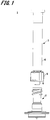
- Fig. 1 is an exploded side view of a drug injection device according to one embodiment of the present invention.
- Fig. 2 is a sectional view illustrating enlarged main portions of the drug injection device illustrated in Fig. 1 .
- a drug injection device 1 is used to puncture a skin surface by a needle tip and inject a drug.
- the drug injection device 1 is for intradermal injection, for injecting a drug in a skin upper layer portion.
- the skin is composed of three portions of epidermis, dermis and subcutaneous tissues.
- the epidermis is a layer which is approximately 50 to 200 ⁇ m from a skin surface
- the dermis is a layer which is approximately 1.5 to 3.5 mm from the epidermis.
- An influenza vaccine is generally administered by subcutaneous administration or intramuscular administration, and therefore is administered to a lower layer portion of the skin or a deeper portion than this lower layer portion.
- the skin upper layer portion refers to the epidermis and the dermis of the skin.
- the drug injection device 1 according to the present embodiment is the drug injection device 1 for intradermal injection at a target site of such a skin upper layer portion.
- the drug injection device 1 includes a needle assembly 2, and a syringe (drug container) 3 to which the needle assembly 2 is detachably attached.
- a plunger for pushing out a drug is inserted in the syringe 3.
- an end portion of the syringe 3 connected to the needle assembly 2 is provided with a lock mechanism 5.
- the syringe 3 includes a syringe main body 4, a drug ejection portion 6 which continues to this syringe main body 4, and the lock mechanism 5 which is provided at an outer circumference of the drug ejection portion 6.
- the syringe main body 4 is composed of a cylindrical member and, as illustrated in Fig. 2 , an interior of the cylinder is a drug containing portion 7 which contains a drug.
- the drug ejection portion 6 is provided at one end of the syringe main body 4 in an axial direction, and is composed of a cylindrical member which is connected to the drug containing portion 7.
- the drug ejection portion 6 is formed in a male tapered shape whose outer diameter is smaller than the syringe main body 4 and becomes smaller toward a distal end.
- a taper rate is expressed in fraction such as A/100 or in percentage such as A% when, for example, a diameter becomes thinner by A mm per 100 mm in length.
- an expanded portion 8 formed by expanding a diameter of a cylindrical hole 9 is formed at a distal end side of the cylindrical hole 9 of the drug ejection portion 6 .
- the depth of this expanded portion 8, i.e., the length from a distal end 6a of the drug ejection portion 6 to an end surface 8a of the expanded portion 8 in an axial direction is approximately 0.4 mm to 0.6 mm.
- a dose is approximately 0.1 to 0.3 mL and is less than those of subcutaneous injection and intramuscular injection. Therefore, it is necessary to reduce a dead volume of the syringe main body 4 to prevent a drug from being wasted.
- the drug ejection portion 6 is generally thicker than common syringes, and is concerned to bend a core pin of a mold during molding.
- the expanded portion 8 is formed to prevent the core pin from being bent.
- a flat surface orthogonal to an axial center direction of the distal end 6a is formed at the distal end 6a of the drug ejection portion 6, and an outer shape of the flat surface, i.e., a distal end outer rim of the drug ejection portion 6 is formed in a circular shape.
- the flat surface of the distal end 6a of the drug ejection portion 6 and a side surface (a side surface of the tapered shape) of the drug ejection portion 6 are connected at the distal end outer rim of the drug ejection portion 6.
- the flat surface of the distal end 6a of this drug ejection portion 6 comes into contact with an end surface of an elastic member 16 of the needle assembly 2 in a liquid-tight manner when attached to the needle assembly 2.
- the syringe main body 4 and the drug ejection portion 6 are formed of a synthetic resin (plastic) .
- a material of this synthetic resin is, for example, polycarbonate, polypropylene, polyethylene, cyclo-olef in polymer or the like.
- the lock mechanism 5 is provided to cover the outer circumference surface of the drug ejection portion 6, and includes a lock main body portion 10 which is described below and is fixed to the needle assembly 2, and a lock mechanism fixing portion 11 which fixes the lock main body portion 10 to the drug ejection portion 6.
- the lock main body portion 10 is composed of a cylindrical member which coaxially surrounds the drug ejection portion 6.
- the lock main body portion 10 has an inner circumference of a circular shape and an outer circumference of a hexagonal shape to allow a user to easily turn the lock main body portion 10.
- a female screw portion 23 is formed in an inner circumference surface of the lock main body portion 10. This female screw portion 23 is formed so as to allow the male screw portion 21 formed in a fitting portion 18 of the needle assembly 2 described below to be screwed therein.
- the female screw portion 23 is formed as a thread groove of a double helical shape.
- the lock mechanism fixing portion 11 is integrally formed with the lock main body portion 10 at an end portion of the lock main body portion 10 at the side of the syringe main body 4.
- the lock mechanism fixing portion 11 is composed of a hollow disk-shaped formed to reduce an inner diameter of the lock main body portion 10.An inner circumference surface of the lock mechanism fixing portion 11 facing the drug ejection portion 6 is provided with the fitting claws 11a which fit to the drug ejection portion 6.
- An inner diameter of the lock mechanism fixing portion 11 is formed slightly larger than the outer diameter of the drug ejection portion 6.
- the fitting claws 11a are formed protruding in a radial direction from the inner circumference surface of the lock mechanism fixing portion 11 facing the drug ejection portion 6, and a plurality of fitting claws 11a are formed on the inner circumference surface of the lock mechanism fixing portion 11 at equal intervals.
- the lock mechanism 5 employing such a configuration is composed of a member different from the syringe 3, and is fixed by fitting the fitting claws 11a to the recessed portion 6b formed in an outer circumference surface of the proximal end of the drug ejection portion 6.
- the lock mechanism 5 can be formed by using the same material as that of the syringe main body 4 and the drug ejection portion 6.
- the needle assembly 2 includes a needle tube 12 and a needle hub 13 that retains the needle tube 12. Further, before the needle assembly 2 is connected with the syringe 3, the needle assembly 2 is detachably attached to a cap 50 as illustrated in Fig. 4 .
- a needle tube of a 26 to 33 gauge size (outer diameter is 0.2 to 0.45 mm) according to medical needle tube standards of ISO (ISO9626:1991/Amd.1:2001(E)) is used, and, more preferably, a needle tube of a 30 to 33 gauge size is used.
- a needle tip 12a that includes a blade surface is formed at a distal end of the needle tube 12.
- the other end of the needle tube 12, which is at a side opposite to the needle tip 12a, will be referred to as a "proximal end 12b" below.
- the length of the needle tube 12 on the blade surface in the axial direction (such a length will be referred to as a "bevel length” below) needs to be 1.4 mm (adult) or less which is the least thickness of the skin upper layer portion described below, and needs to be approximately 0 . 5 mm or more which is the bevel length in case where a short bevel is formed in a 33-gauge needle tube. That is, the bevel length is preferably set to a range of 0.5 to 1.4 mm.
- the bevel length is more preferably 0. 9 mm (child) or less which is the least thickness of the skin upper layer portion, i.e., a bevel length B is more preferably in a range of 0.5 to 0.9 mm.
- the short bevel refers to a blade surface that forms an 18° to 25° angle with respect to a longitudinal direction of a needle, which is generally used for a needle.
- a material of the needle tube 12 is, for example, stainless steel yet is not limited to this .
- Other metals such as aluminum, aluminum alloy, titanium and titanium alloy can be used for this material.
- the needle tube 12 not only a straight needle but also a tapered needle which is at least partially tapered can be used.
- the tapered needle needs to have a base end portion which has a larger diameter than a needle tip end portion, and an intermediate portion which adopts a tapered structure.
- a sectional shape of the needle tube 12 may be not only a circular shape but also a polygonal shape such as a triangular shape.
- the needle hub 13 includes a first member 14 which is provided with the fitting portion 18 to which the drug ejection portion 6 of the syringe 3 is fitted, a second member 15 (a retaining portion according to the present invention) which retains the needle tube 12, and the elastic member 16 which is sandwiched between the drug ejection portion 6 and the second member 15 during assembly of the drug injection device 1.
- the first member 14 and the second member 15 forming the needle hub 13 are formed by using different members yet may be integrally formed.
- the first member 14 is entirely formed in a nearly cylindrical shape.
- a limiting portion 17 which limits a force to be applied to the lock mechanism 5, the fitting portion 18 to which the drug ejection portion 6 is fitted, an intermediate portion 19 in which the elastic member 16 is inserted and an insertion portion 20 in which the second member 15 is inserted are formed in order from a side at which the drug ejection portion 6 is inserted.
- a cylindrical hole 18b of the fitting portion 18 is set to a size matching the drug ejection portion 6 of the syringe 3, and an opening end at one end side is a fitting opening 18a fitted to the drug ejection portion 6. Further, the diameter of the fitting portion 18 becomes continuously smaller from an end portion of the fitting opening 18a toward the insertion portion 20.
- Fig. 3 is an enlarged sectional view of the fitting portion 18 of the first member 14. Configurations of the fitting portion 18 and the limiting portion 17 will be described in more detail with reference to Fig. 3 .
- the fitting portion 18 includes a fitting wall 18c, which fits to the drug ejection portion 6 in an inner wall of the cylindrical hole 18b.
- the fitting portion 18 preferably includes a guide wall 18d in the inner wall of the cylindrical hole 18b at a side of the fitting opening 18a.
- the fitting wall 18c is formed in such a female tapered shape that an inner diameter of the cylindrical hole 18b becomes continuously smaller from the side of the fitting opening 18a toward a side of the insertion portion 20.
- This tapered shape is formed with a taper rate of M > 100 where M > N holds.
- M is a positive number.
- the fitting wall 18c is formed such that the inner diameter of the cylindrical hole 18b can be fitted to the drug ejection portion 6 of the syringe 3.
- K represents the diameter of the distal end of the drug ejection portion 6
- Dmax represents the diameter (maximum diameter) of the fitting wall 18c at the side of the fitting opening 18a
- Dmin represents the diameter (minimum diameter) of the fitting wall 18c at the side of the insertion portion 20
- the cylindrical hole 18b corresponding to the fitting wall 18c is formed to provide a relationship of Dmax > K > Dmin.
- the distal end of the fitted drug ejection portion 6 is positioned at the position slightly closer to the side of the insertion portion 20 than the position at which the diameter of the cylindrical hole 18b is K.
- the guide wall 18d is formed by expanding the inner diameter of the cylindrical hole 18b at the side of the fitting opening 18a.
- This guide wall 18d is preferably formed by expanding the inner diameter of the cylindrical hole 18b at the side of the fitting opening 18a compared to a case where the entire cylindrical hole 18b is formed by the fitting wall 18c at the tapered rate of M/100.
- the guide wall 18d is preferably formed in such a tapered shape that the inner diameter of the cylindrical hole 18b becomes smaller from the side of the fitting opening 18a toward the side of the insertion portion 20.
- the length of the guide wall 18d in the axial line direction is approximately 0.5 L to 2 L when, for example, L represents the length of the fitting wall 18c in the axial line direction.
- the guide wall 18d and the fitting wall 18c are not preferably connected in a stepwise shape to prevent leakage of a drug solution due to damage on the distal end of the drug ejection portion 6. That is, as illustrated in Fig. 3 , an angle d at which the connection wall 18e of a tapered shape whose diameter at the side of the insertion portion 20 becomes small or the connection wall 18e which is formed by curves connects the guide wall 18d and the fitting wall 18c is preferably formed at an obtuse angle (90° ⁇ d ⁇ 180°) and is more preferably formed at 120° ⁇ d ⁇ 180°.
- a second screw portion (referred to as a male screw portion 21) to which the female screw portion 23 of the lock mechanism 5 is screwed is formed on an outer circumference surface of the fitting portion 18.
- the male screw portion 21 is formed as a thread of a double helical shape.
- the male screw portion 21 may be a screw of a single helical shape.
- the limiting portion 17 is formed at the end portion of the fitting opening 18a of the fitting portion 18, and includes a cylindrical member including a cylindrical hole continuing to the cylindrical hole 18b of the fitting portion 18.
- An outer circumference surface of the limiting portion 17 and an outer circumference surface of the fitting portion 18 are formed as a continuous surface, and an outer diameter of the continuous surface is formed to be substantially the same as an outer diameter of the fitting portion 18 at the side of the fitting opening 18a.
- an inner circumference surface of the limiting portion 17 and an inner circumference surface of the fitting portion 18 are formed as a continuous surface, and an inner diameter of the continuous surface is formed to be slightly larger than an inner diameter of the fitting opening 18a of the fitting portion 18.
- the length of the limiting portion 17 in the axial direction is set to come into contact with the lock mechanism fixing portion 11 of the lock mechanism 5 during assembly of the drug injection device 1.
- the limiting portion 17 is a portion provided to limit a pushing force applied to the lock mechanism 5 to push and assemble the drug ejection portion 6 of the syringe 3 to the fitting portion 18 of the needle assembly 2. A function of this limiting portion 17 will be described in detail below.
- a cylindrical hole 22 of the insertion portion 20 is set to a size matching a base portion 33 of the second member 15.
- the insertion portion 20 is provided with a fixing piece 34 which is connected to a connection piece 24 of the second member 15 described below.
- This fixing piece 34 is formed as a flange of a ring shape which continues to a distal end of the insertion portion 20 and protrudes in a radially outer direction.
- a planar surface 24b of the connection piece 24 provided to the second member 15 comes into contact with and is fixed to the fixing piece 34.
- a method for fixing the fixing piece 34 and the connection piece 24 includes, for example, an adhesive, ultrasonic welding, laser welding, a fixing screw and the like.
- the intermediate portion 19 is formed between the insertion portion 20 and the fitting portion 18, and includes a cylindrical hole 26 whose diameter is smaller than a cylindrical hole 22 of the insertion portion 20.
- a step surface at a boundary between the cylindrical hole 22 forming the insertion portion 20 and the cylindrical hole 26 forming the intermediate portion 19 is an engagement portion 26a with which the elastic member 16 engages.
- a flange portion 42 of the elastic member 16 described below engages with this engagement portion 26a.
- the second member 15 is provided with a skin contact portion 30 which faces and/or contacts a skin.
- the skin contact portion 30 is disposed to cover surroundings of the needle tube 12 when the needle tube 12 is attached to the second member 15.
- This skin contact portion 30 includes a base portion 33 of a nearly columnar shape, an adjusting portion 31, a stable portion 36 and a guide portion 32.
- the base portion 33 includes end surfaces 33a and 33b vertical to the axial direction.
- the adjusting portion 31 is formed at a center portion of the end surface 33a at one end side of the base portion 33 in the axial direction, and includes a protrusion portion of a columnar shape protruding in the axial direction of the base portion 33. An axial center of this adjusting portion 31 matches with an axial center of the base portion 33.
- a through-hole 25 through which the needle tube 12 penetrates is formed at the axial centers of the base portion 33 and the adjusting portion 31. Further, an injection hole 35 through which an adhesive (not illustrated) is injected in the through-hole 25 is formed in the base portion 33. This injection hole 35 is opened in an outer circumference surface of the base portion 33, and continues to the through-hole 25 nearly orthogonally to the through-hole 25 although not illustrated in Fig. 2 . That is, the adhesive injected to the through-hole 25 through the injection hole 35 fixes the needle tube 12 to the base portion 33.
- the proximal end 12b of the needle tube 12 protrudes from an end surface 33b which is the other end of the base portion 33 in the axial direction.
- the base portion 33 is inserted in the first member 14 from a side of the end surface 33b, and a side of the proximal end 12b of the needle tube 12 is inserted in an insertion hole 43 of the elastic member 16 described below. Further, the end surface 33b of the base portion 33 is placed in contact with an end surface 41a of the elastic member 16 described below.
- connection piece 24 is provided on an outer circumference surface of the base portion 33.
- This connection piece 24 is formed as a flange of a ring shape protruding to an outside of a radial direction of the base portion 33, and includes planar surfaces 24a and 24b opposing in the axial direction of the base portion 33.
- the planar surface 24b of the connection piece 24 is connected with the first member 14.
- a distal end portion of the connection piece 24 is the guide portion 32. This guide portion 32 will be described in detail below.
- An end surface of the adjusting portion 31 is a needle protrusion surface 31a from which a side of the needle tip 12a of the needle tube 12 protrudes.
- the needle protrusion surface 31a is formed as a planar surface orthogonal to the axial direction of the needle tube 12 .
- This needle protrusion surface 31a comes into contact with a skin surface and defines a puncturing depth of the needle tube 12 when the needle tube 12 punctures a skin upper layer portion. That is, the puncturing depth of the needle tube 12 with respect to the skin upper layer portion is determined according to a protrusion length of the needle tube 12 (referred to as a "protrusion length L" below) from the needle protrusion surface 31a.
- the thickness of the skin upper layer portion corresponds to the depth from the skin surface to a dermis layer, and is roughly in a range of 0.5 to 3.0 mm.
- the protrusion length L of the needle tube 12 can be set to a range of 0.5 to 3.0 mm.
- a vaccine is generally administered to an upper arm portion yet is preferably administered to a shoulder proximity portion of a thick skin and a deltoid portion when administration of the vaccine to a skin upper layer portion is taken into account.
- the thicknesses of the skin upper layer of deltoids of 19 children and 31 adults were measured.
- This measurement was conducted to capture images of the skin upper layer portions of a high ultrasonic reflectance by using an ultrasonic measuring device (NP60R-UBM small animal high resolution echo device manufactured by Nepa Gene Co., Ltd).
- measurement values were provided in a lognormal distribution, and therefore a range of MEAN ⁇ 2SD was calculated by geometric mean.
- the thicknesses of the skin upper layer portions of the deltoids of the children were 0.9 to 1.6 mm. Further, the thicknesses of the skin upper layer portions of the deltoids of the adults were 1.4 to 2.6 mm at distal portions, 1.4 to 2.5 mm at center portions and 1.5 to 2.5 mm at proximal portions. In view of the above, it was confirmed that the thicknesses of the skin upper layer portions of the deltoids were 0.9 mm or more in case of the children and 1.4 mm or more in case of the adults.
- the protrusion length L of the needle tube 12 is preferably set to the range of 0.9 to 1.4 mm for injection with respect to the skin upper layer portion of the deltoid.
- the protrusion length L By setting the protrusion length L in this way, it is possible to reliably position the blade surface of the needle tip 12a at the skin upper layer portion. As a result, even when a needle hole (drug outlet) opened in the blade surface is any position on the blade surface, the needle hole can be positioned at the skin upper layer portion. In this regard, even when the drug outlet is positioned at the skin upper layer portion, if the needle tip 12a deeply punctures the skin upper layer portion, a drug solution leaks below the skin from between a side surface of an end portion of the needle tip 12a and a skin cut open. Therefore, it is important to reliably place the blade surface at the skin upper layer portion.
- a needle tube thicker than a 26 gauge has difficulty in making a bevel length 1.0 mm or less.
- a needle tube thinner than the 26 gauge to set the protrusion length L of the needle tube 12 to a desired range (0.9 to 1.4 mm).
- the needle protrusion surface 31a is formed such that a distance S from a periphery to a circumference surface of the needle tube 12 is 1.4 mm or less, and is preferably formed in a range of 0.3 to 1.4 mm.
- the distance S from the periphery of this needle protrusion surface 31a to the circumference surface of the needle tube 12 is set by taking into account that a pressure is applied to wheals formed when a drug is administered to the skin upper layer portion. That is, the needle protrusion surface 31a is set to a size which is sufficiently smaller than wheals formed at the skin upper layer portion and does not prevent formation of wheals. As a result, the needle protrusion surface 31a can press the skin around the needle tube 12 and prevent leakage of the administered drug.
- the stable portion 36 is formed in a cylindrical shape protruding from the planar surface 24a of the connection piece 24 provided to the base portion 33.
- the needle tube 12 and the adjusting portion 31 are disposed in a cylindrical hole of the stable portion 36. That is, the stable portion 36 is formed in the cylindrical shape covering the surroundings of the adjusting portion 31 through which the needle tube 12 penetrates, and is formed apart from the needle tip 12a of the needle tube 12 in the radial direction.
- an end surface 36a of the stable portion 36 is positioned closer to the side of the proximal end 12b of the needle tube 12 than the needle protrusion surface 31a of the adjusting portion 31 is.
- the needle protrusion surface 31a first comes into contact with a skin surface and then comes into contact with the end surface 36a of the stable portion 36.
- the end surface 36a of the stable portion 36 comes into contact with the skin, so that it is possible to stabilize the drug injection device 1 and keep the needle tube 12 at a posture nearly vertical to the skin.
- a distance between the end surface 36a of the stable portion 36 and the needle protrusion surface 31a in the axial direction is preferably set to 1.3 mm or less.
- an inner diameter of the stable portion 36 is set to a value equal to or larger than the diameter of the wheals formed on the skin. More specifically, a distance T from an inner wall surface of the stable portion 36 to the periphery of the needle protrusion surface 31a is set to a range of 4 mm to 15 mm. Consequently, it is possible to prevent a pressure from being applied from the inner wall surface of the stable portion 36 to the wheals and thereby preventing formation of the wheals.
- the shortest distance T from the inner wall surface of the stable portion 36 to an outer circumference surface of the adjusting portion 31 has no upper limit in particular as long as the shortest distance T is 4 mm or more.
- the distance T is preferably defined as 15 mm at maximum when thinness of children's arms is taken into account.
- the adjusting portion 31 does not enter a skin. Consequently, when the distance T (4 mm or more) from the inner wall surface of the stable portion 36 to the periphery of the needle protrusion surface 31a and the diameter (approximately 0.3 mm) of the needle protrusion surface 31a are taken into account, it is possible to set the inner diameter of the stable portion 36 to 9 mm or more.
- the shape of the stable portion 36 is not limited to a cylindrical shape, and may be, for example, a square tube shape such as a quadrangular prism and a hexagonal prism having a cylindrical hole at a center.
- the cap 50 is detachably fitted to the stable portion 36 (see Fig. 4 ) .
- This cap 50 covers the needle tip 12a of the needle tube 12. Consequently, when the needle hub 13 is attached to the syringe 3, it is possible to prevent the needle tip 12a from contacting a fingertip of a user and the like. Further, it is possible to keep a safe state of the used drug injection device 1 or needle assembly 2 at all times, and the user can safety dispose the used drug injection device 1 or needle assembly 2.
- the guide portion 32 is a distal end side portion of the second member 15 positioned closer to the outside of the radial direction than the stable portion 36 of the connection piece 24 is.
- This guide portion 32 includes a contact surface 32a that contacts the skin.
- the contact surface 32a is part of the planar surface 24a of the connection piece 24, and is a planar surface nearly parallel to the end surface 36a of the stable portion 36.
- the length of a distance (referred to as a "guide portion height" below) Y from the contact surface 32a of the guide portion 32 to the end surface 36a of the stable portion 36 is set to enable the needle tube 12 and the stable portion 36 to press and puncture the skin by an appropriate force.
- the appropriate pressing force of the needle tube 12 and the stable portion 36 is, for example, 3 to 20 N.
- the guide portion 32 guides for the user the pressing force of the needle tube 12 and the stable portion 36 to the skin, and it is possible to reliably position the needle tip 12a (blade surface) of the needle tube 12 at the skin upper layer portion and make the user feel safe.
- the height Y of the guide portion 32 is optionally determined based on the inner diameter of the stable portion 36 and a length (referred to as a "guide portion length" below) X from a distal end surface of the guide portion 32 to an outer circumference surface of the stable portion 36.
- a guide portion length referred to as a "guide portion length” below
- the guide portion height Y is set to a range of 2.3 to 6.6 mm.
- the elastic member 16 is disposed inside the cylindrical hole 26 which is the intermediate portion 19 of the first member 14, and is interposed between the first member 14 and the syringe 3.
- This elastic member 16 includes a deformation portion 40, a main body portion 41 and a flange portion 42 provided at one end of this main body portion 41 in the axial direction, and the deformation portion 40, the main body portion 41 and the flange portion 42 are integrally formed.
- the main body portion 41 is formed in a nearly cylindrical shape, and the end surface 41a at a side opposite to a side at which the deformation portion 40 is formed comes into contact with the end surface 33b of the base portion 33 of the second member 15. Further, an outer diameter of the main body portion 41 is formed slightly larger than an inner diameter of an inner wall surface of the fitting portion 18 at the side of the insertion portion 20 provided to the first member 14. Thus, elasticity of the elastic member 16 allows the elastic member 16 to be retained liquid-tight at the side of the insertion portion 20 of the fitting portion 18.
- the flange portion 42 is formed on an outer circumference surface of the main body portion 41 at the side of the end surface 41a, and is formed in a ring shape protruding from the outer circumference surface of the main body portion 41 in the radially outer direction.
- the flange portion 42 is formed larger than an inner diameter of the intermediate portion 19 which retains the main body portion 41, and smaller than an inner diameter of the insertion portion 20 .
- one planar surface of the flange portion 42 comes into contact with the engagement portion 26a formed as a step shape between the intermediate portion 19 of the first member 14 and the insertion portion 20, and the other planar surface comes into contact with the end surface 33b of the base portion 33 of the second member 15.
- the engagement portion 26a of the first member 14 and the base portion 33 of the second member 15 sandwich the flange portion 42, so that the elastic member 16 is fixed to the needle hub 13.
- the deformation portion 40 is composed of a cylindrical member provided at a side opposite to the side of the end surface 41a of the main body portion 41 which comes into contact with the base portion 33.
- An outer diameter of the deformation portion 40 is formed equally to or a little smaller than the outer diameter of the main body portion 41.
- a side surface of the deformation portion 40 is formed continuing to a side surface of the main body portion 41, and an inner wall surface of the deformation portion 40 is formed continuing to an inner wall surface of the main body portion 41.
- an end surface 40a of the deformation portion 40 at a side opposite to a side of the main body portion 41 is a contact surface which comes into contact with the distal end 6a of the drug ejection portion 6.
- the user fits the drug ejection portion 6 to the fitting portion 18 to connect the syringe 3 and the needle assembly 2 and assemble the drug injection device 1.
- a fitting depth and strength of the drug ejection portion 6 with respect to the fitting portion 18 differ per user.
- variations of dimensional tolerances of molded articles change a fitting depth of the drug ejection portion 6 with respect to the fitting portion 18.
- the present embodiment employs a configuration where the deformation portion 40 deforms accompanying the distal end of the drug ejection portion 6, so that it is possible to provide an effect of reducing a dead volume produced by a difference in a fitting depth of the drug ejection portion 6 with respect to the fitting portion 18.
- the deformation portion 40 is formed, so that it is possible to reduce the dead volume produced by a difference in the fitting depth to 10 ⁇ L or less.
- the main body portion 41 also deforms more or less accompanying deformation of the deformation portion 40.
- a dimension of the elastic member 16 will be described with reference to Fig. 3 .
- a length A3 of the deformation portion 40 in the axial direction is 35% shorter than a length A1 of the entire elastic member 16 in the axial direction, a deformable width of the elastic member 16 in the axial direction becomes small, and a dead volume produced by a fitting depth difference varying per user is higher than 10 ⁇ L.
- the length A3 of the deformation portion 40 in the axial direction is 50% longer than the length A1 of the entire elastic member 16 in the axial direction, a deformation amount of the elastic member becomes large, and a liquid passing failure is highly likely to occur.
- the length A3 of the deformation portion 40 in the axial direction is preferably configured to be 35% or more and 50% or less with respect to the length A1 of the entire elastic member 16 in the axial direction.
- the elastic member 16 is provided with the insertion hole 43 through which the side of the proximal end 12b of the needle tube 12 protruding from the end surface 33b of the base portion 33 is inserted in the axial direction of the main body portion 41 and the deformation portion 40.
- An end surface side spaced portion 46, a contact surface side spaced portion 48 and a close contact portion 47 are formed on an inner wall surface of the insertion hole 43.
- the end surface side spaced portion 46 includes the inner wall surface of the insertion hole 43 at the side of the main body portion 41, and forms an opening of the insertion hole 43 on the end surface 41a of the main body portion 41.
- This end surface side spaced portion 46 is spaced apart from an outer circumference surface of the needle tube 12, and is formed in such a tapered shape that the diameter of the insertion hole 43 becomes continuously larger toward the end surface 41a. Consequently, it is possible to easily insert the side of the proximal end 12b of the needle tube 12 protruding from the end surface 33b of the base portion 33 in the insertion hole 43.
- the shape of the end surface side spaced portion 46 in the insertion hole 43 is not limited to the tapered shape as long as this tapered shape allows the needle tube 12 to be easily inserted in the insertion hole 43.
- the contact surface side spaced portion 48 includes the inner wall surface of the insertion hole 43 at a side of the deformation portion 40, and forms the opening of the insertion hole 43 on the end surface 40a at the side of the deformation portion 40.
- This contact surface side spaced portion 48 is spaced apart from the outer circumference surface of the needle tube 12. Further, the inner wall surface forming the contact surface side spaced portion 48 is formed nearly parallel to the axial direction of the deformation portion 40.
- the deformation portion 40 is likely to block the proximal end 12b of the needle tube 12 during assembly of the drug injection device 1 depending on a protrusion length of the needle tube 12 toward the contact surface side spaced portion 48.
- the protrusion length of the needle tube 12 from the close contact portion 47 toward the deformation portion 40 to prevent this block will be described below.
- the inner wall surface of the insertion hole 43 forming the contact surface side spaced portion 48 is formed nearly parallel to the axial direction of the deformation portion 40.
- the inner wall surface may be formed in such a tapered shape that the diameter of the insertion hole 43 continuously becomes larger from the close contact portion 47 toward an end surface of the deformation portion 40. That is, a shape of the contact surface side spaced portion 48 in the insertion hole 43 needs to be a shape which makes the deformation portion 40 hardly block the needle hole of the needle tube 12 when the deformation portion 40 elastically deforms.
- the close contact portion 47 is formed between the end surface side spaced portion 46 and the contact surface side spaced portion 48, and is formed near a boundary between the main body portion 41 and the deformation portion 40.
- the close contact portion 47 is in close contact with the outer circumference surface of the needle tube 12 in a liquid-tight manner.
- a protrusion length A2 (see Fig. 3 ) of the needle tube 12 from the close contact portion 47 toward the contact surface side spaced portion 48 (toward the fitting portion 18) is set to such a length that, when the deformation portion 40 of the elastic member 16 is crushed against the distal end 6a of the drug ejection portion 6, the proximal end 12b of the needle tube 12 is exposed from the cylindrical hole 9 of the drug ejection portion 6 and does not damage the cylindrical hole 9 of the drug ejection portion 6.
- the proximal end 12b of the needle tube 12 needs to be exposed toward the cylindrical hole 9 of the drug ejection portion 6 such that the deformation portion 40 does not completely block the needle hole, a liquid can pass and the user has no difficulty in administering the drug.
- the length A2 of the needle tube 12 protruding from the close contact portion 47 toward the fitting opening 18a is 245% longer than the length A3 of the deformation portion 40 in the axial direction, there is a concern that, for example, the drug ejection portion 6 is fitted to the fitting portion 18 obliquely with respect to the axial direction of the fitting portion 18, and the proximal end 12b of the needle tube 12 exposed in the cylindrical hole 9 of the drug ejection portion 6 damages the cylindrical hole 9 of the drug ejection portion 6.
- the length A2 of the needle tube 12 protruding from the close contact portion 47 toward the fitting portion 18 is preferably set to a range of 45% or more and 245% or less with respect to the length A3 of the deformation portion 40 in the axial direction.
- the length A2 is preferably 1.4 mm or more and 7.5 mm or less.
- the length A3 is preferably 2.5 mm or more and 3.1 mm or less.
- this elastic member 16 is provided, so that, when the syringe 3 and the needle assembly 2 are connected, the distal end 6a of the drug ejection portion 6 crushes the deformation portion 40 of the elastic member 16 and thereby the distal end 6a of the drug ejection portion 6 and the end surface of the deformation portion 40 of the elastic member 16 contact each other in a liquid-tight manner. Further, the needle tube 12 is exposed from a distal end of the crushed deformation portion 40 toward the drug ejection portion 6, so that the cylindrical hole 9 of the drug ejection portion 6 and the needle tube 12 continue to each other.
- a material of the elastic member 16 may be any of various rubber materials such as natural rubber and silicone rubber, various thermoplastic elastomers such as polyurethane elastomers and styrene elastomers and elastic materials of mixture thereof.
- the needle assembly 2 employing the above configuration is manufactured as follows. First, the needle tube 12 is inserted in the through-hole 25 of the base portion 33 of the second member 15. The adhesive is injected through the injection hole 35 formed in the base portion 33 in a state where the needle tip 12a of the needle tube 12 is protruded from the adjusting portion 31 by a defined length for puncturing a skin to adhere and fix the second member 15 and the needle tube 12. Next, the elastic member 16 is inserted in the intermediate portion 19 of the first member 14.
- the adhesive is applied on the guide portion 32 of the second member 15, and the base portion 33 of the second member 15 is inserted in the insertion portion 20 of the first member 14 to adhere and fix the fixing piece 34 of the first member 14 and the guide portion 32 of the second member 15, .
- the needle assembly 2 is manufactured such that the length A2 of the needle tube 12 protruding from the close contact portion 47 toward the fitting portion 18 is preferably set to a range of 45% or more and 245% or less with respect to the length A3 of the deformation portion 40 in the axial direction. Thus, the needle assembly 2 is finished.
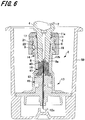
- FIGs. 4 and 6 are views illustrating how the drug ejection portion 6 of the syringe 3 is fitted to the needle assembly 2 to assemble the drug injection device 1.
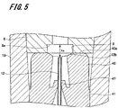
- Fig. 5 is an enlarged view of main portions in Fig. 4
- Fig. 7 is an enlarged view of main portions in Fig. 6 .
- the drug ejection portion 6 of the syringe 3 is inserted in the fitting portion 18 of the needle assembly in a state where the needle assembly 2 is housed in the cap 50.
- the distal end of the drug ejection portion 6 is inserted in the cylindrical hole 18b through the fitting opening 18a of the fitting portion 18.
- an inner diameter of the guide wall 18d is formed larger than an outer diameter of the distal end 6a of the drug ejection portion 6, and therefore the distal end 6a of the drug ejection portion 6 is easily inserted in the fitting opening 18a.
- the drug ejection portion 6 is further inserted in the cylindrical hole 18b.
- the connection wall 18e is obliquely formed in the tapered shape, so that the drug ejection portion 6 smoothly slides and moves along an inner wall of the cylindrical hole 18b. Consequently, it is possible to prevent the distal end 6a of the drug ejection portion 6 from being damaged.
- the drug ejection portion 6 is inserted in the cylindrical hole 18b until the female screw portion 23 of the lock mechanism 5 contacts the male screw portion 21 of the fitting portion 18, and then the needle assembly 2 and the lock mechanism 5 are relatively turned to screw the male screw portion 21 and the female screw portion 23.
- the lock mechanism 5 is fixed to the syringe 3, so that, by rotating the syringe 3, the user can screw the male screw portion 21 and the female screw portion 23. Further, tightening this lock mechanism 5 in this way deeply inserts the drug ejection portion 6 in the cylindrical hole 18b of the fitting portion 18.
- a taper rate of the fitting wall 18c is set higher than the taper rate of the drug ejection portion 6, so that only the distal end outer rim of drug ejection portion 6 contacts the fitting wall 18c.
- Fig. 4 illustrates the state where the distal end 6a of the drug ejection portion 6 is fitted to the fitting wall 18c of the fitting portion 18 without applying a force much, and the syringe 3 is turned with respect to the needle assembly 2 at a connection torque of 0.05 N ⁇ m to screw the lock mechanism 5 and the fitting portion 18, and place the distal end 6a of the drug ejection portion 6 in contact with the deformation portion 40 of the elastic member 16.
- Fig. 5 is a view illustrating the enlarged deformation portion 40 in the state in Fig. 4 .
- the distance Xa from the end surface 8a of the expanded portion 8 in the axial direction to the needle tube 12 is defined based on the end surface 8a of the expanded portion 8 (zero) with a side in contact with the elastic member 16 as a positive direction and a side of the drug containing portion 7 as a negative direction.
- the distance Xa takes a plus value when the proximal end 12b of the needle tube 12 is closer to the elastic member 16 than the end surface 8a is as illustrated in Fig. 5 , and takes a minus value when the proximal end 12b is closer to the drug containing portion 7.
- the first member 14 is formed by using a synthetic resin. Hence, material characteristics of the first member 14 allow the fitting wall 18c to deform in a recessed shape when the drug ejection portion 6 is inserted in the fitting portion 18 until the end surface of the limiting portion 17 comes into contact with the bottom surface of the lock mechanism fixing portion 11. Thus, the distal end outer rim of the drug ejection portion 6 bites the fitting wall 18c. Thus, the distal end outer rim of the drug ejection portion 6 and the fitting wall 18c are placed in close contact, and the drug ejection portion 6 and the fitting wall 18c are fixed in a liquid-tight manner.
- the deformation portion 40 of the elastic member 16 is crushed by the drug ejection portion 6 and bites the expanded portion 8 formed at the distal end of the drug ejection portion 6.
- the end surface 8a of the expanded portion 8 in the axial direction and the distal end 6a of the drug ejection portion 6, and the end surface of the deformation portion 40 of the elastic member 16 contact each other in a liquid-tight manner.
- the cylindrical hole 9 of the drug ejection portion 6 and the needle tube 12 continue to each other.
- Fig. 7 is a view illustrating the enlarged deformation portion 40 in the state in Fig. 6 .
- the proximal end 12b of the needle tube 12 protrudes from the close contact portion 47 toward the cylindrical hole 9 of the drug ejection portion 6 by a predetermined distance Xb when the assembly is finished. Consequently, it is possible to prevent the deformation portion 40 from blocking the proximal end 12b of the needle tube 12 and causing a liquid passing failure.
- the distance Xb from the end surface 8a of the expanded portion 8 in the axial direction to the needle tube 12 is also defined based on the end surface 8a of the expanded portion 8 (zero) with the side in contact with the elastic member 16 as the positive direction and the side of the drug containing portion 7 as the negative direction.
- the distance Xb takes a plus value when the proximal end 12b of the needle tube 12 is closer to the elastic member 16 than the end surface 8a is, and takes a minus value when the proximal end 12b is closer to the drug containing portion 7 as illustrated in Fig. 7 .
- Xb is preferably 0 mm or more and 6.0 mm or less.
- an insertion depth of the drug ejection portion 6 in the fitting portion 18 differs by user.
- the distal end 6a of the drug ejection portion 6 comes into contact with the deformation portion 40 of the elastic member 16 in a liquid-tight manner. That is, an insertion distance at which the drug ejection portion 6 is inserted in the fitting portion 18 until the limiting portion 17 comes into contact with the lock mechanism fixing portion 11 is a maximum insertion distance, and the drug ejection portion 6 may be locked at a position at which the limiting portion 17 does not come into contact with the lock mechanism fixing portion 11.
- the drug ejection portion 6 of the syringe 3 when the limiting portion 17 comes into contact with the bottom surface of the lock mechanism fixing portion 11, the drug ejection portion 6 of the syringe 3 is not inserted in the fitting portion 18 more. Consequently, it is possible to prevent the fitting claws 11a from being damaged when a pushing force of the drug ejection portion 6 in the fitting portion 18 exceeds a fitting force of the fitting claws 11a and the recessed portion 6b of the drug ejection portion 6, and prevent the lock mechanism 5 from being detached from the drug ejection portion 6.
- the distal end outer rim of the drug ejection portion 6 is formed in a small circular shape, and, when the drug ejection portion 6 is fitted in the fitting portion 18, this small distal end outer rim is pressed against the fitting wall 18c. Further, the taper rate of the male tapered shape of the drug ejection portion 6 is formed lower than the taper rate of the female tapered shape of the fitting portion 18. As a result, a pressure at which the drug ejection portion 6 is pressed against the fitting wall 18c entirely concentrates on a narrow area of the fitting wall 18c which the distal end outer rim of the drug ejection portion 6 contacts. That is, a gap is made more or less between the fitting wall 18c and the side surface of the drug ejection portion 6, and therefore a force concentrates on the distal end outer rim of the drug ejection portion 6.
- the material of the first member 14 is not limited to a relatively soft material like polypropylene, and a relatively hard material such as polycarbonate and cyclo-olefin polymer can be used as long as the material can make the distal end outer rim of the drug ejection portion 6 sufficiently bite the fitting wall 18c.
- a value of M of the taper rate of the fitting wall 18c needs to be optionally determined as a value higher than N.
- the value of M is by far larger than N, the diameter of the cylindrical hole becomes large.
- M 1.5 N to 10 N
- M 2 N to 5 N
- a protrusion length of the needle tube 12 from the close contact portion 47 toward the contact surface side spaced portion 48 is set to such a length that, when the deformation portion 40 of the elastic member 16 is crushed against the distal end 6a of the drug ejection portion 6, the proximal end 12b of the needle tube 12 is exposed from the cylindrical hole 9 of the drug ejection portion 6 without being blocked and does not damage the cylindrical hole 9 of the drug ejection portion 6. Consequently, it is possible to prevent a liquid passing failure.
- the distance Xa from the proximal end 12b of the needle tube 12 to the end surface 8a of the expanded portion 8 in case where the drug ejection portion 6 was fitted and connected to the fitting portion 18 without applying a force much was changed to test a change in the liquid passing state.
- the distance Xa was changed by changing the protrusion length of the needle tube 12 from the close contact portion 47 .
- a contact position of the drug ejection portion 6 which contacts the elastic member 16 illustrated in Figs. 4 and 5 is a reference contact position.
- the depth of the drug ejection portion 6 in the axial direction of the expanded portion 8 was 0.4 to 0.6 6 mm
- the length of the elastic member 16 in the axial direction was 6.5 mm to 6.8 mm
- the outer diameter of the deformation portion 40 was 3.3 mm to 3.5 mm
- the length of the deformation portion 40 in the axial direction was 2.9 mm to 3.1 mm
- the thickness of the deformation portion 40 in the radial direction was in a range of 0.9 mm or more and 1.1 mm or less.
- the user assembled drug injection devices whose distances Xa were set to 0.9 mm to 1.5 mm by applying a higher force than an average force during assembly. More specifically, the user pushed and fitted the drug ejection portion 6 toward the fitting portion 18 by a load of 25 N and rotated the syringe 3 at a connection torque of 0.26 N ⁇ m to screw the lock mechanism 5 to the fitting portion 18 and connect the syringe 3 and the needle assembly 2.
- Table 1 shows that, when the distance Xa between the proximal end 12b of the needle tube 12 and the end surface 8a of the expanded portion 8 was 1 .0 mm or less, the liquid passing failure did not occur. Hence, when a specific value of the distance from the end surface 8a of the expanded portion 8 to the proximal end 12b of the needle tube 12 in a state where the drug ejection portion 6 and the elastic member 16 are in the reference contact state is 1.0 mm or less, it is possible to prevent a liquid passing failure.
- the distance Xa from the end surface 8a of the expanded portion 8 in the axial direction to the needle tube 12 is preferably -5.3 mm or more. That is, a preferable range of the distance Xa is -5.3 mm or more and 1.0 mm or less.
- the distance from the end surface 8a of the expanded portion 8 in the axial direction to the needle tube 12 was defined based on the end surface 8a of the expanded portion 8 (zero) with the side in contact with the elastic member 16 as the positive direction and the side of the fitting portion 18 as the negative direction.
- the drug injection device 1 can prevent a liquid passing failure.
- the distance Xa between the proximal end 12b of the needle tube 12 and the end surface 8a of the expanded portion 8 is set to 1.0 mm or less in terms of a more realistic value based on an actual design of the drug injection device 1, it is possible to prevent the liquid passing failure.
- the deformation portion 40 does not block the proximal end 12b of the needle tube 12 and it is possible to prevent the liquid passing failure.
- the above embodiment employs a configuration including the lock mechanism 5 composed of a different member from that of the drug ejection portion 6.
- the present invention may employ a configuration where the lock mechanism is provided to the drug ejection portion 6.
- the male screw portion on the outer circumference surface of the drug ejection portion 6 and forming on the inner circumference surface of the fitting portion 18 the female screw portion screwed to the male screw portion formed in the drug ejection portion 6, it is possible to fix the drug ejection portion 6 to the fitting portion 18.
Landscapes
- Health & Medical Sciences (AREA)
- Vascular Medicine (AREA)
- Engineering & Computer Science (AREA)
- Anesthesiology (AREA)
- Biomedical Technology (AREA)
- Heart & Thoracic Surgery (AREA)
- Hematology (AREA)
- Life Sciences & Earth Sciences (AREA)
- Animal Behavior & Ethology (AREA)
- General Health & Medical Sciences (AREA)
- Public Health (AREA)
- Veterinary Medicine (AREA)
- Infusion, Injection, And Reservoir Apparatuses (AREA)
Abstract
Description
- The present invention relates to a needle assembly which is fitted to a drug ejection portion of a drug container such as an injection syringe to use, and a drug injection device which includes such needle assembly.
- In some drug injection devices, a syringe that contains an injection drug, and a needle assembly that includes a needle are separately formed, and the needle assembly is attached to a drug ejection portion at a cylindrical tip of the syringe and is used for injection (Patent Literature 1).
- A needle assembly is generally attached to a drug ejection portion by taper fitting. More specifically, the drug ejection portion is formed in a male tapered shape (truncated conical shape) whose outer diameter continuously becomes smaller toward a distal end. The needle assembly is provided with a fitting portion including a cylindrical hole, and this fitting portion is formed in a female tapered shape (truncated conical shape) that has a size matching the drug ejection portion and whose inner diameter continuously becomes smaller from an opening including the cylindrical hole. The male tapered shape and the female tapered shape are formed at the same taper rate. By pressuring a drug ejection tube and pushing the fitting portion, surfaces of the tapered shapes press against each other and are fixed in liquid-tight manner.
- Patent Literature 1:
JP 2011-212185 A - By the way, in a drug injection device in which a drug container such as a syringe and a needle assembly are connected by taper fitting, a side of a retained needle tube of the needle assembly inserted in a drug ejection portion is inserted in an elastic member. Thus, the elastic member and the needle assembly are retained in a liquid-tight manner, so that it is possible to prevent leakage of a drug toward a needle tip. Further, when the drug ejection portion is fitted to the fitting portion of the needle assembly, a distal end of the drug ejection portion comes into contact with an end surface of the elastic member. Thus, it is possible to reduce a dead volume due to a difference in a connection force of a user for connecting an injection syringe to a drug injection device or a difference in a fitting depth caused by a dimensional error between the drug injection device and the injection syringe.
- However, the elastic member deforms when the drug ejection portion comes into contact with the elastic member. Therefore, it is possible to reduce a dead volume when the drug ejection portion comes into contact with the elastic member and the elastic member deforms by adjusting a length of a needle tube inserted in the elastic member. However, the deformed elastic member can block a proximal end of the needle tube at a side of a drug ejection portion, and a liquid passing failure can occur. Further, when the drug ejection portion comes into contact with the elastic member and the elastic member deforms to a greater extent, the liquid passing failure is more likely to occur.
- It is therefore an object of the present invention to provide a needle assembly that prevents a liquid passing failure, and a drug injection device which includes such a needle assembly.
- A needle assembly according to one embodiment of the present invention is a needle assembly that is connectable to a drug container such as a syringe including a drug ejection portion having a male tapered shape with an outer diameter that becomes smaller toward a distal end. The needle assembly includes: a needle tube that includes at a distal end a needle tip configured to puncture skin; a retaining portion that includes a fitting portion including a fitting opening in which the drug ejection portion is insertable, and formed in a female tapered shape, and which retains the needle tube in a state where a proximal end of the needle tube protrudes toward the fitting opening; and an elastic member that is located in the fitting portion, and includes a close contact portion that closely contacts and retains a proximal end side of the needle tube protruding toward the fitting opening, and a deformation portion that extends from the close contact portion toward the fitting opening and deforms when the drug ejection portion comes into contact with the elastic member, and in which a length of the deformation portion is in a range of 35% or more and 50% or less with respect to a length of the elastic member, and a length of the needle tube which protrudes from the close contact portion toward the fitting portion is in a range of 45% or more and 245% or less with respect to the deformation portion.
- Further, a drug injection device according to the present invention includes: a drug container such as a syringe that includes a drug ejection portion of a cylindrical shape formed in a male tapered shape whose outer diameter becomes smaller toward a distal end; and the above-described needle assembly according to the present invention.
- According to the present invention, it is possible to provide a needle assembly which prevents a liquid passing failure, and a drug injection device that includes such a needle assembly.
-
-
Fig. 1 is an exploded side view of a drug injection device according to one embodiment of the present invention. -
Fig. 2 is a sectional view illustrating enlarged main portions of the drug injection device illustrated inFig. 1 . -
Fig. 3 is an enlarged sectional view of a fitting portion of a first member. -
Fig. 4 is a view (part 1) illustrating how a drug ejection portion of a syringe is fitted to a needle assembly to assemble the drug injection device. -
Fig. 5 is an enlarged view of main portions inFig. 4 . -
Fig. 6 is a view (part 2) illustrating how the drug ejection portion of the syringe is fitted to the needle assembly to assemble the drug injection device. -
Fig. 7 is an enlarged view of main portions inFig. 6 . - An example of a needle assembly and a drug injection device according to an embodiment of the present invention will be described with reference to the drawings. The present invention is not limited to the following example. This description will be described in the following order.
- 1. Configurations of Needle Assembly and Drug Injection Device
- 2. Method for Assembling Drug Injection Device
-
Fig. 1 is an exploded side view of a drug injection device according to one embodiment of the present invention.Fig. 2 is a sectional view illustrating enlarged main portions of the drug injection device illustrated inFig. 1 . Adrug injection device 1 is used to puncture a skin surface by a needle tip and inject a drug. In the present embodiment, thedrug injection device 1 is for intradermal injection, for injecting a drug in a skin upper layer portion. - In this regard, the skin is composed of three portions of epidermis, dermis and subcutaneous tissues. The epidermis is a layer which is approximately 50 to 200 µm from a skin surface, and the dermis is a layer which is approximately 1.5 to 3.5 mm from the epidermis. An influenza vaccine is generally administered by subcutaneous administration or intramuscular administration, and therefore is administered to a lower layer portion of the skin or a deeper portion than this lower layer portion.
- Generally, administering an influenza vaccine to a target site of a skin upper layer portion including multiple immunocompetent cells to decrease a vaccine dose is studied. In this regard, the skin upper layer portion refers to the epidermis and the dermis of the skin. The
drug injection device 1 according to the present embodiment is thedrug injection device 1 for intradermal injection at a target site of such a skin upper layer portion. - As illustrated in
Fig. 1 , thedrug injection device 1 according to the present embodiment includes aneedle assembly 2, and a syringe (drug container) 3 to which theneedle assembly 2 is detachably attached. Although not illustrated, a plunger for pushing out a drug is inserted in thesyringe 3. Further, an end portion of thesyringe 3 connected to theneedle assembly 2 is provided with alock mechanism 5. - The
syringe 3 includes a syringemain body 4, adrug ejection portion 6 which continues to this syringemain body 4, and thelock mechanism 5 which is provided at an outer circumference of thedrug ejection portion 6. The syringemain body 4 is composed of a cylindrical member and, as illustrated inFig. 2 , an interior of the cylinder is adrug containing portion 7 which contains a drug. Thedrug ejection portion 6 is provided at one end of the syringemain body 4 in an axial direction, and is composed of a cylindrical member which is connected to thedrug containing portion 7. - The
drug ejection portion 6 is formed in a male tapered shape whose outer diameter is smaller than the syringemain body 4 and becomes smaller toward a distal end. In this regard, a taper rate is expressed in fraction such as A/100 or in percentage such as A% when, for example, a diameter becomes thinner by A mm per 100 mm in length. In the present embodiment, the male tapered shape forming thedrug ejection portion 6 is formed at N/100. N is a positive number. More specifically, the male tapered shape is formed at N = 6 which is also referred to as a luer taper in accordance with ISO594-1 or ISO594-2. - Further, as illustrated in
Fig. 2 , an expandedportion 8 formed by expanding a diameter of acylindrical hole 9 is formed at a distal end side of thecylindrical hole 9 of thedrug ejection portion 6 . The depth of this expandedportion 8, i.e., the length from adistal end 6a of thedrug ejection portion 6 to anend surface 8a of the expandedportion 8 in an axial direction is approximately 0.4 mm to 0.6 mm. When injection is performed for the skin upper layer portion, a dose is approximately 0.1 to 0.3 mL and is less than those of subcutaneous injection and intramuscular injection. Therefore, it is necessary to reduce a dead volume of the syringemain body 4 to prevent a drug from being wasted. Hence, thedrug ejection portion 6 is generally thicker than common syringes, and is concerned to bend a core pin of a mold during molding. The expandedportion 8 is formed to prevent the core pin from being bent. - A flat surface orthogonal to an axial center direction of the
distal end 6a is formed at thedistal end 6a of thedrug ejection portion 6, and an outer shape of the flat surface, i.e., a distal end outer rim of thedrug ejection portion 6 is formed in a circular shape. The flat surface of thedistal end 6a of thedrug ejection portion 6 and a side surface (a side surface of the tapered shape) of thedrug ejection portion 6 are connected at the distal end outer rim of thedrug ejection portion 6. The flat surface of thedistal end 6a of thisdrug ejection portion 6 comes into contact with an end surface of anelastic member 16 of theneedle assembly 2 in a liquid-tight manner when attached to theneedle assembly 2. Further, a recessedportion 6b in whichfitting claws 11a of thelock mechanism 5 described below are formed in an outer circumference surface of an end portion (referred to a proximal end below) of thedrug ejection portion 6 at a side of the syringemain body 4. - For example, the syringe
main body 4 and thedrug ejection portion 6 are formed of a synthetic resin (plastic) . A material of this synthetic resin is, for example, polycarbonate, polypropylene, polyethylene, cyclo-olef in polymer or the like. - The
lock mechanism 5 is provided to cover the outer circumference surface of thedrug ejection portion 6, and includes a lockmain body portion 10 which is described below and is fixed to theneedle assembly 2, and a lockmechanism fixing portion 11 which fixes the lockmain body portion 10 to thedrug ejection portion 6. - The lock
main body portion 10 is composed of a cylindrical member which coaxially surrounds thedrug ejection portion 6. The lockmain body portion 10 has an inner circumference of a circular shape and an outer circumference of a hexagonal shape to allow a user to easily turn the lockmain body portion 10. Afemale screw portion 23 is formed in an inner circumference surface of the lockmain body portion 10. Thisfemale screw portion 23 is formed so as to allow themale screw portion 21 formed in afitting portion 18 of theneedle assembly 2 described below to be screwed therein. In the present embodiment, thefemale screw portion 23 is formed as a thread groove of a double helical shape. - The lock
mechanism fixing portion 11 is integrally formed with the lockmain body portion 10 at an end portion of the lockmain body portion 10 at the side of the syringemain body 4. The lockmechanism fixing portion 11 is composed of a hollow disk-shaped formed to reduce an inner diameter of the lock main body portion 10.An inner circumference surface of the lockmechanism fixing portion 11 facing thedrug ejection portion 6 is provided with thefitting claws 11a which fit to thedrug ejection portion 6. An inner diameter of the lockmechanism fixing portion 11 is formed slightly larger than the outer diameter of thedrug ejection portion 6. Thefitting claws 11a are formed protruding in a radial direction from the inner circumference surface of the lockmechanism fixing portion 11 facing thedrug ejection portion 6, and a plurality offitting claws 11a are formed on the inner circumference surface of the lockmechanism fixing portion 11 at equal intervals. - The
lock mechanism 5 employing such a configuration is composed of a member different from thesyringe 3, and is fixed by fitting thefitting claws 11a to the recessedportion 6b formed in an outer circumference surface of the proximal end of thedrug ejection portion 6. Thelock mechanism 5 can be formed by using the same material as that of the syringemain body 4 and thedrug ejection portion 6. - The
needle assembly 2 includes aneedle tube 12 and aneedle hub 13 that retains theneedle tube 12. Further, before theneedle assembly 2 is connected with thesyringe 3, theneedle assembly 2 is detachably attached to acap 50 as illustrated inFig. 4 . - For the
needle tube 12, a needle tube of a 26 to 33 gauge size (outer diameter is 0.2 to 0.45 mm) according to medical needle tube standards of ISO (ISO9626:1991/Amd.1:2001(E)) is used, and, more preferably, a needle tube of a 30 to 33 gauge size is used. - A
needle tip 12a that includes a blade surface is formed at a distal end of theneedle tube 12. The other end of theneedle tube 12, which is at a side opposite to theneedle tip 12a, will be referred to as a "proximal end 12b" below. The length of theneedle tube 12 on the blade surface in the axial direction (such a length will be referred to as a "bevel length" below) needs to be 1.4 mm (adult) or less which is the least thickness of the skin upper layer portion described below, and needs to be approximately 0 . 5 mm or more which is the bevel length in case where a short bevel is formed in a 33-gauge needle tube. That is, the bevel length is preferably set to a range of 0.5 to 1.4 mm. - Further, the bevel length is more preferably 0. 9 mm (child) or less which is the least thickness of the skin upper layer portion, i.e., a bevel length B is more preferably in a range of 0.5 to 0.9 mm. In this regard, the short bevel refers to a blade surface that forms an 18° to 25° angle with respect to a longitudinal direction of a needle, which is generally used for a needle.
- A material of the
needle tube 12 is, for example, stainless steel yet is not limited to this . Other metals such as aluminum, aluminum alloy, titanium and titanium alloy can be used for this material. Further, for theneedle tube 12, not only a straight needle but also a tapered needle which is at least partially tapered can be used. The tapered needle needs to have a base end portion which has a larger diameter than a needle tip end portion, and an intermediate portion which adopts a tapered structure. Further, a sectional shape of theneedle tube 12 may be not only a circular shape but also a polygonal shape such as a triangular shape. - The
needle hub 13 includes afirst member 14 which is provided with thefitting portion 18 to which thedrug ejection portion 6 of thesyringe 3 is fitted, a second member 15 (a retaining portion according to the present invention) which retains theneedle tube 12, and theelastic member 16 which is sandwiched between thedrug ejection portion 6 and thesecond member 15 during assembly of thedrug injection device 1. In the present embodiment, thefirst member 14 and thesecond member 15 forming theneedle hub 13 are formed by using different members yet may be integrally formed. - The
first member 14 is entirely formed in a nearly cylindrical shape. In thefirst member 14, a limitingportion 17 which limits a force to be applied to thelock mechanism 5, thefitting portion 18 to which thedrug ejection portion 6 is fitted, anintermediate portion 19 in which theelastic member 16 is inserted and aninsertion portion 20 in which thesecond member 15 is inserted are formed in order from a side at which thedrug ejection portion 6 is inserted. - A
cylindrical hole 18b of thefitting portion 18 is set to a size matching thedrug ejection portion 6 of thesyringe 3, and an opening end at one end side is afitting opening 18a fitted to thedrug ejection portion 6. Further, the diameter of thefitting portion 18 becomes continuously smaller from an end portion of thefitting opening 18a toward theinsertion portion 20. -
Fig. 3 is an enlarged sectional view of thefitting portion 18 of thefirst member 14. Configurations of thefitting portion 18 and the limitingportion 17 will be described in more detail with reference toFig. 3 . Thefitting portion 18 includes afitting wall 18c, which fits to thedrug ejection portion 6 in an inner wall of thecylindrical hole 18b. As illustrated inFig. 3 , thefitting portion 18 preferably includes aguide wall 18d in the inner wall of thecylindrical hole 18b at a side of thefitting opening 18a. Thefitting wall 18c is formed in such a female tapered shape that an inner diameter of thecylindrical hole 18b becomes continuously smaller from the side of thefitting opening 18a toward a side of theinsertion portion 20. This tapered shape is formed with a taper rate of M > 100 where M > N holds. M is a positive number. In this example, M takes a value larger than 6 to match the taper rate of N/100 (N = 6 in the present embodiment) for the outer diameter of thedrug ejection portion 6. - The
fitting wall 18c is formed such that the inner diameter of thecylindrical hole 18b can be fitted to thedrug ejection portion 6 of thesyringe 3. When K represents the diameter of the distal end of thedrug ejection portion 6, Dmax represents the diameter (maximum diameter) of thefitting wall 18c at the side of thefitting opening 18a, and Dmin represents the diameter (minimum diameter) of thefitting wall 18c at the side of theinsertion portion 20, thecylindrical hole 18b corresponding to thefitting wall 18c is formed to provide a relationship of Dmax > K > Dmin. The distal end of the fitteddrug ejection portion 6 is positioned at the position slightly closer to the side of theinsertion portion 20 than the position at which the diameter of thecylindrical hole 18b is K. - The
guide wall 18d is formed by expanding the inner diameter of thecylindrical hole 18b at the side of thefitting opening 18a. Thisguide wall 18d is preferably formed by expanding the inner diameter of thecylindrical hole 18b at the side of thefitting opening 18a compared to a case where the entirecylindrical hole 18b is formed by thefitting wall 18c at the tapered rate of M/100. Theguide wall 18d is preferably formed in such a tapered shape that the inner diameter of thecylindrical hole 18b becomes smaller from the side of thefitting opening 18a toward the side of theinsertion portion 20. - The length of the
guide wall 18d in the axial line direction is approximately 0.5 L to 2 L when, for example, L represents the length of thefitting wall 18c in the axial line direction. - Further, the
guide wall 18d and thefitting wall 18c are not preferably connected in a stepwise shape to prevent leakage of a drug solution due to damage on the distal end of thedrug ejection portion 6. That is, as illustrated inFig. 3 , an angle d at which theconnection wall 18e of a tapered shape whose diameter at the side of theinsertion portion 20 becomes small or theconnection wall 18e which is formed by curves connects theguide wall 18d and thefitting wall 18c is preferably formed at an obtuse angle (90° < d < 180°) and is more preferably formed at 120° ≤ d ≤ 180°. - A second screw portion (referred to as a male screw portion 21) to which the
female screw portion 23 of thelock mechanism 5 is screwed is formed on an outer circumference surface of thefitting portion 18. In the present embodiment, themale screw portion 21 is formed as a thread of a double helical shape. In this regard, themale screw portion 21 may be a screw of a single helical shape. - The limiting
portion 17 is formed at the end portion of thefitting opening 18a of thefitting portion 18, and includes a cylindrical member including a cylindrical hole continuing to thecylindrical hole 18b of thefitting portion 18. An outer circumference surface of the limitingportion 17 and an outer circumference surface of thefitting portion 18 are formed as a continuous surface, and an outer diameter of the continuous surface is formed to be substantially the same as an outer diameter of thefitting portion 18 at the side of thefitting opening 18a. Further, an inner circumference surface of the limitingportion 17 and an inner circumference surface of thefitting portion 18 are formed as a continuous surface, and an inner diameter of the continuous surface is formed to be slightly larger than an inner diameter of thefitting opening 18a of thefitting portion 18. - Furthermore, the length of the limiting
portion 17 in the axial direction is set to come into contact with the lockmechanism fixing portion 11 of thelock mechanism 5 during assembly of thedrug injection device 1. The limitingportion 17 is a portion provided to limit a pushing force applied to thelock mechanism 5 to push and assemble thedrug ejection portion 6 of thesyringe 3 to thefitting portion 18 of theneedle assembly 2. A function of this limitingportion 17 will be described in detail below. - Next, a configuration of the
insertion portion 20 will be described with reference back toFig. 2 . Acylindrical hole 22 of theinsertion portion 20 is set to a size matching abase portion 33 of thesecond member 15. Theinsertion portion 20 is provided with a fixingpiece 34 which is connected to aconnection piece 24 of thesecond member 15 described below. This fixingpiece 34 is formed as a flange of a ring shape which continues to a distal end of theinsertion portion 20 and protrudes in a radially outer direction. Aplanar surface 24b of theconnection piece 24 provided to thesecond member 15 comes into contact with and is fixed to the fixingpiece 34. A method for fixing the fixingpiece 34 and theconnection piece 24 includes, for example, an adhesive, ultrasonic welding, laser welding, a fixing screw and the like. - The
intermediate portion 19 is formed between theinsertion portion 20 and thefitting portion 18, and includes acylindrical hole 26 whose diameter is smaller than acylindrical hole 22 of theinsertion portion 20. A step surface at a boundary between thecylindrical hole 22 forming theinsertion portion 20 and thecylindrical hole 26 forming theintermediate portion 19 is anengagement portion 26a with which theelastic member 16 engages. Aflange portion 42 of theelastic member 16 described below engages with thisengagement portion 26a. - The
second member 15 is provided with askin contact portion 30 which faces and/or contacts a skin. Theskin contact portion 30 is disposed to cover surroundings of theneedle tube 12 when theneedle tube 12 is attached to thesecond member 15. Thisskin contact portion 30 includes abase portion 33 of a nearly columnar shape, an adjustingportion 31, astable portion 36 and aguide portion 32. - The
base portion 33 includes end surfaces 33a and 33b vertical to the axial direction. The adjustingportion 31 is formed at a center portion of theend surface 33a at one end side of thebase portion 33 in the axial direction, and includes a protrusion portion of a columnar shape protruding in the axial direction of thebase portion 33. An axial center of this adjustingportion 31 matches with an axial center of thebase portion 33. - A through-
hole 25 through which theneedle tube 12 penetrates is formed at the axial centers of thebase portion 33 and the adjustingportion 31. Further, aninjection hole 35 through which an adhesive (not illustrated) is injected in the through-hole 25 is formed in thebase portion 33. Thisinjection hole 35 is opened in an outer circumference surface of thebase portion 33, and continues to the through-hole 25 nearly orthogonally to the through-hole 25 although not illustrated inFig. 2 . That is, the adhesive injected to the through-hole 25 through theinjection hole 35 fixes theneedle tube 12 to thebase portion 33. - The
proximal end 12b of theneedle tube 12 protrudes from anend surface 33b which is the other end of thebase portion 33 in the axial direction. Thebase portion 33 is inserted in thefirst member 14 from a side of theend surface 33b, and a side of theproximal end 12b of theneedle tube 12 is inserted in aninsertion hole 43 of theelastic member 16 described below. Further, theend surface 33b of thebase portion 33 is placed in contact with anend surface 41a of theelastic member 16 described below. - Furthermore, the
connection piece 24 is provided on an outer circumference surface of thebase portion 33. Thisconnection piece 24 is formed as a flange of a ring shape protruding to an outside of a radial direction of thebase portion 33, and includesplanar surfaces base portion 33. Theplanar surface 24b of theconnection piece 24 is connected with thefirst member 14. Further, a distal end portion of theconnection piece 24 is theguide portion 32. Thisguide portion 32 will be described in detail below. - An end surface of the adjusting
portion 31 is aneedle protrusion surface 31a from which a side of theneedle tip 12a of theneedle tube 12 protrudes. Theneedle protrusion surface 31a is formed as a planar surface orthogonal to the axial direction of theneedle tube 12 . Thisneedle protrusion surface 31a comes into contact with a skin surface and defines a puncturing depth of theneedle tube 12 when theneedle tube 12 punctures a skin upper layer portion. That is, the puncturing depth of theneedle tube 12 with respect to the skin upper layer portion is determined according to a protrusion length of the needle tube 12 (referred to as a "protrusion length L" below) from theneedle protrusion surface 31a. - The thickness of the skin upper layer portion corresponds to the depth from the skin surface to a dermis layer, and is roughly in a range of 0.5 to 3.0 mm. Hence, the protrusion length L of the
needle tube 12 can be set to a range of 0.5 to 3.0 mm. - A vaccine is generally administered to an upper arm portion yet is preferably administered to a shoulder proximity portion of a thick skin and a deltoid portion when administration of the vaccine to a skin upper layer portion is taken into account. Hence, the thicknesses of the skin upper layer of deltoids of 19 children and 31 adults were measured. This measurement was conducted to capture images of the skin upper layer portions of a high ultrasonic reflectance by using an ultrasonic measuring device (NP60R-UBM small animal high resolution echo device manufactured by Nepa Gene Co., Ltd). In this regard, measurement values were provided in a lognormal distribution, and therefore a range of MEAN ± 2SD was calculated by geometric mean.
- A measurement result showed that the thicknesses of the skin upper layer portions of the deltoids of the children were 0.9 to 1.6 mm. Further, the thicknesses of the skin upper layer portions of the deltoids of the adults were 1.4 to 2.6 mm at distal portions, 1.4 to 2.5 mm at center portions and 1.5 to 2.5 mm at proximal portions. In view of the above, it was confirmed that the thicknesses of the skin upper layer portions of the deltoids were 0.9 mm or more in case of the children and 1.4 mm or more in case of the adults. Hence, the protrusion length L of the
needle tube 12 is preferably set to the range of 0.9 to 1.4 mm for injection with respect to the skin upper layer portion of the deltoid. - By setting the protrusion length L in this way, it is possible to reliably position the blade surface of the
needle tip 12a at the skin upper layer portion. As a result, even when a needle hole (drug outlet) opened in the blade surface is any position on the blade surface, the needle hole can be positioned at the skin upper layer portion. In this regard, even when the drug outlet is positioned at the skin upper layer portion, if theneedle tip 12a deeply punctures the skin upper layer portion, a drug solution leaks below the skin from between a side surface of an end portion of theneedle tip 12a and a skin cut open. Therefore, it is important to reliably place the blade surface at the skin upper layer portion. - In this regard, in case of use for administration to the skin upper layer portion, a needle tube thicker than a 26 gauge has difficulty in making a bevel length 1.0 mm or less. Hence, it is preferable to use a needle tube thinner than the 26 gauge to set the protrusion length L of the
needle tube 12 to a desired range (0.9 to 1.4 mm). - The
needle protrusion surface 31a is formed such that a distance S from a periphery to a circumference surface of theneedle tube 12 is 1.4 mm or less, and is preferably formed in a range of 0.3 to 1.4 mm. The distance S from the periphery of thisneedle protrusion surface 31a to the circumference surface of theneedle tube 12 is set by taking into account that a pressure is applied to wheals formed when a drug is administered to the skin upper layer portion. That is, theneedle protrusion surface 31a is set to a size which is sufficiently smaller than wheals formed at the skin upper layer portion and does not prevent formation of wheals. As a result, theneedle protrusion surface 31a can press the skin around theneedle tube 12 and prevent leakage of the administered drug. - The
stable portion 36 is formed in a cylindrical shape protruding from theplanar surface 24a of theconnection piece 24 provided to thebase portion 33. Theneedle tube 12 and the adjustingportion 31 are disposed in a cylindrical hole of thestable portion 36. That is, thestable portion 36 is formed in the cylindrical shape covering the surroundings of the adjustingportion 31 through which theneedle tube 12 penetrates, and is formed apart from theneedle tip 12a of theneedle tube 12 in the radial direction. - As illustrated in
Fig. 2 , anend surface 36a of thestable portion 36 is positioned closer to the side of theproximal end 12b of theneedle tube 12 than theneedle protrusion surface 31a of the adjustingportion 31 is. When theneedle tip 12a of theneedle tube 12 punctures a biological body, theneedle protrusion surface 31a first comes into contact with a skin surface and then comes into contact with theend surface 36a of thestable portion 36. In this case, theend surface 36a of thestable portion 36 comes into contact with the skin, so that it is possible to stabilize thedrug injection device 1 and keep theneedle tube 12 at a posture nearly vertical to the skin. - In this regard, even when the
end surface 36a of thestable portion 36 is positioned on the same plane as theneedle protrusion surface 31a or is positioned closer to the side of theneedle tip 12a of theneedle tube 12 than theneedle protrusion surface 31a is, it is possible to keep theneedle tube 12 at a posture nearly vertical to the skin. In this regard, when a bulge of the skin caused when thestable portion 36 is pressed against the skin is taken into account, a distance between theend surface 36a of thestable portion 36 and theneedle protrusion surface 31a in the axial direction is preferably set to 1.3 mm or less. - Further, an inner diameter of the
stable portion 36 is set to a value equal to or larger than the diameter of the wheals formed on the skin. More specifically, a distance T from an inner wall surface of thestable portion 36 to the periphery of theneedle protrusion surface 31a is set to a range of 4 mm to 15 mm. Consequently, it is possible to prevent a pressure from being applied from the inner wall surface of thestable portion 36 to the wheals and thereby preventing formation of the wheals. - The shortest distance T from the inner wall surface of the
stable portion 36 to an outer circumference surface of the adjustingportion 31 has no upper limit in particular as long as the shortest distance T is 4 mm or more. However, when the distance T is increased, an outer diameter of thestable portion 36 becomes large, and therefore, when theneedle tube 12 punctures a thin arm like a child, it is difficult to place theentire end surface 36a of thestable portion 36 in contact with a skin. Hence, the distance T is preferably defined as 15 mm at maximum when thinness of children's arms is taken into account. - Further, when the distance S from the periphery of the
needle protrusion surface 31a to the circumference surface of theneedle tube 12 is 0.3 mm or more, the adjustingportion 31 does not enter a skin. Consequently, when the distance T (4 mm or more) from the inner wall surface of thestable portion 36 to the periphery of theneedle protrusion surface 31a and the diameter (approximately 0.3 mm) of theneedle protrusion surface 31a are taken into account, it is possible to set the inner diameter of thestable portion 36 to 9 mm or more. - In this regard, the shape of the
stable portion 36 is not limited to a cylindrical shape, and may be, for example, a square tube shape such as a quadrangular prism and a hexagonal prism having a cylindrical hole at a center. - Further, the
cap 50 is detachably fitted to the stable portion 36 (seeFig. 4 ) . Thiscap 50 covers theneedle tip 12a of theneedle tube 12. Consequently, when theneedle hub 13 is attached to thesyringe 3, it is possible to prevent theneedle tip 12a from contacting a fingertip of a user and the like. Further, it is possible to keep a safe state of the useddrug injection device 1 orneedle assembly 2 at all times, and the user can safety dispose the useddrug injection device 1 orneedle assembly 2. - The
guide portion 32 is a distal end side portion of thesecond member 15 positioned closer to the outside of the radial direction than thestable portion 36 of theconnection piece 24 is. Thisguide portion 32 includes acontact surface 32a that contacts the skin. Thecontact surface 32a is part of theplanar surface 24a of theconnection piece 24, and is a planar surface nearly parallel to theend surface 36a of thestable portion 36. By pressing thestable portion 36 until thecontact surface 32a of theguide portion 32 contacts the skin, it is possible to secure a force of thestable portion 36 and theneedle tube 12 for pressing the skin at a predetermined value or more at all times. Thus, the portion (corresponding to the protrusion length L) of theneedle tube 12 protruding from theneedle protrusion surface 31a reliably punctures the skin. - The length of a distance (referred to as a "guide portion height" below) Y from the
contact surface 32a of theguide portion 32 to theend surface 36a of thestable portion 36 is set to enable theneedle tube 12 and thestable portion 36 to press and puncture the skin by an appropriate force. In this regard, the appropriate pressing force of theneedle tube 12 and thestable portion 36 is, for example, 3 to 20 N. As a result, theguide portion 32 guides for the user the pressing force of theneedle tube 12 and thestable portion 36 to the skin, and it is possible to reliably position theneedle tip 12a (blade surface) of theneedle tube 12 at the skin upper layer portion and make the user feel safe. - The height Y of the
guide portion 32 is optionally determined based on the inner diameter of thestable portion 36 and a length (referred to as a "guide portion length" below) X from a distal end surface of theguide portion 32 to an outer circumference surface of thestable portion 36. When, for example, an inner diameter D of thestable portion 36 is 12 mm and the guide portion length X is 3 . 0 mm, the guide portion height Y is set to a range of 2.3 to 6.6 mm. - Next, the
elastic member 16 will be described. Theelastic member 16 is disposed inside thecylindrical hole 26 which is theintermediate portion 19 of thefirst member 14, and is interposed between thefirst member 14 and thesyringe 3. Thiselastic member 16 includes adeformation portion 40, amain body portion 41 and aflange portion 42 provided at one end of thismain body portion 41 in the axial direction, and thedeformation portion 40, themain body portion 41 and theflange portion 42 are integrally formed. - The
main body portion 41 is formed in a nearly cylindrical shape, and theend surface 41a at a side opposite to a side at which thedeformation portion 40 is formed comes into contact with theend surface 33b of thebase portion 33 of thesecond member 15. Further, an outer diameter of themain body portion 41 is formed slightly larger than an inner diameter of an inner wall surface of thefitting portion 18 at the side of theinsertion portion 20 provided to thefirst member 14. Thus, elasticity of theelastic member 16 allows theelastic member 16 to be retained liquid-tight at the side of theinsertion portion 20 of thefitting portion 18. - The
flange portion 42 is formed on an outer circumference surface of themain body portion 41 at the side of theend surface 41a, and is formed in a ring shape protruding from the outer circumference surface of themain body portion 41 in the radially outer direction. Theflange portion 42 is formed larger than an inner diameter of theintermediate portion 19 which retains themain body portion 41, and smaller than an inner diameter of theinsertion portion 20 . Hence, one planar surface of theflange portion 42 comes into contact with theengagement portion 26a formed as a step shape between theintermediate portion 19 of thefirst member 14 and theinsertion portion 20, and the other planar surface comes into contact with theend surface 33b of thebase portion 33 of thesecond member 15. Theengagement portion 26a of thefirst member 14 and thebase portion 33 of thesecond member 15 sandwich theflange portion 42, so that theelastic member 16 is fixed to theneedle hub 13. - The
deformation portion 40 is composed of a cylindrical member provided at a side opposite to the side of theend surface 41a of themain body portion 41 which comes into contact with thebase portion 33. An outer diameter of thedeformation portion 40 is formed equally to or a little smaller than the outer diameter of themain body portion 41. A side surface of thedeformation portion 40 is formed continuing to a side surface of themain body portion 41, and an inner wall surface of thedeformation portion 40 is formed continuing to an inner wall surface of themain body portion 41. Further, anend surface 40a of thedeformation portion 40 at a side opposite to a side of themain body portion 41 is a contact surface which comes into contact with thedistal end 6a of thedrug ejection portion 6. During assembly of thedrug injection device 1, thedeformation portion 40 is pushed by thedistal end 6a of thedrug ejection portion 6 and is crushed toward themain body portion 41. - When using the
drug injection device 1 according to the present embodiment, the user fits thedrug ejection portion 6 to thefitting portion 18 to connect thesyringe 3 and theneedle assembly 2 and assemble thedrug injection device 1. Hence, a fitting depth and strength of thedrug ejection portion 6 with respect to thefitting portion 18 differ per user. Further, variations of dimensional tolerances of molded articles change a fitting depth of thedrug ejection portion 6 with respect to thefitting portion 18. By contrast with this, the present embodiment employs a configuration where thedeformation portion 40 deforms accompanying the distal end of thedrug ejection portion 6, so that it is possible to provide an effect of reducing a dead volume produced by a difference in a fitting depth of thedrug ejection portion 6 with respect to thefitting portion 18. In the present embodiment, thedeformation portion 40 is formed, so that it is possible to reduce the dead volume produced by a difference in the fitting depth to 10 µL or less. In this regard, in theelastic member 16, themain body portion 41 also deforms more or less accompanying deformation of thedeformation portion 40. - Hereinafter, a dimension of the
elastic member 16 will be described with reference toFig. 3 . When a length A3 of thedeformation portion 40 in the axial direction is 35% shorter than a length A1 of the entireelastic member 16 in the axial direction, a deformable width of theelastic member 16 in the axial direction becomes small, and a dead volume produced by a fitting depth difference varying per user is higher than 10 µL. Further, when the length A3 of thedeformation portion 40 in the axial direction is 50% longer than the length A1 of the entireelastic member 16 in the axial direction, a deformation amount of the elastic member becomes large, and a liquid passing failure is highly likely to occur. Hence, the length A3 of thedeformation portion 40 in the axial direction is preferably configured to be 35% or more and 50% or less with respect to the length A1 of the entireelastic member 16 in the axial direction. - Further, in the present embodiment, the
elastic member 16 is provided with theinsertion hole 43 through which the side of theproximal end 12b of theneedle tube 12 protruding from theend surface 33b of thebase portion 33 is inserted in the axial direction of themain body portion 41 and thedeformation portion 40. An end surface side spacedportion 46, a contact surface side spacedportion 48 and aclose contact portion 47 are formed on an inner wall surface of theinsertion hole 43. - The end surface side spaced
portion 46 includes the inner wall surface of theinsertion hole 43 at the side of themain body portion 41, and forms an opening of theinsertion hole 43 on theend surface 41a of themain body portion 41. This end surface side spacedportion 46 is spaced apart from an outer circumference surface of theneedle tube 12, and is formed in such a tapered shape that the diameter of theinsertion hole 43 becomes continuously larger toward theend surface 41a. Consequently, it is possible to easily insert the side of theproximal end 12b of theneedle tube 12 protruding from theend surface 33b of thebase portion 33 in theinsertion hole 43. In this regard, the shape of the end surface side spacedportion 46 in theinsertion hole 43 is not limited to the tapered shape as long as this tapered shape allows theneedle tube 12 to be easily inserted in theinsertion hole 43. - The contact surface side spaced
portion 48 includes the inner wall surface of theinsertion hole 43 at a side of thedeformation portion 40, and forms the opening of theinsertion hole 43 on theend surface 40a at the side of thedeformation portion 40. This contact surface side spacedportion 48 is spaced apart from the outer circumference surface of theneedle tube 12. Further, the inner wall surface forming the contact surface side spacedportion 48 is formed nearly parallel to the axial direction of thedeformation portion 40. By providing the contact surface side spacedportion 48 to theelastic member 16, it is possible to prevent thedeformation portion 40 from covering theproximal end 12b of theneedle tube 12 and blocking the needle hole when thedeformation portion 40 elastically deforms. In this regard, even when the contact surface side spacedportion 48 is provided, thedeformation portion 40 is likely to block theproximal end 12b of theneedle tube 12 during assembly of thedrug injection device 1 depending on a protrusion length of theneedle tube 12 toward the contact surface side spacedportion 48. The protrusion length of theneedle tube 12 from theclose contact portion 47 toward thedeformation portion 40 to prevent this block will be described below. - The inner wall surface of the
insertion hole 43 forming the contact surface side spacedportion 48 is formed nearly parallel to the axial direction of thedeformation portion 40. However, the inner wall surface may be formed in such a tapered shape that the diameter of theinsertion hole 43 continuously becomes larger from theclose contact portion 47 toward an end surface of thedeformation portion 40. That is, a shape of the contact surface side spacedportion 48 in theinsertion hole 43 needs to be a shape which makes thedeformation portion 40 hardly block the needle hole of theneedle tube 12 when thedeformation portion 40 elastically deforms. - The
close contact portion 47 is formed between the end surface side spacedportion 46 and the contact surface side spacedportion 48, and is formed near a boundary between themain body portion 41 and thedeformation portion 40. Theclose contact portion 47 is in close contact with the outer circumference surface of theneedle tube 12 in a liquid-tight manner. Thus, it is possible to prevent a drug in thesyringe 3 from infiltrating toward thesecond member 15 of theneedle hub 13 from between theneedle tube 12 and theelastic member 16. - A protrusion length A2 (see
Fig. 3 ) of theneedle tube 12 from theclose contact portion 47 toward the contact surface side spaced portion 48 (toward the fitting portion 18) is set to such a length that, when thedeformation portion 40 of theelastic member 16 is crushed against thedistal end 6a of thedrug ejection portion 6, theproximal end 12b of theneedle tube 12 is exposed from thecylindrical hole 9 of thedrug ejection portion 6 and does not damage thecylindrical hole 9 of thedrug ejection portion 6. In this regard, theproximal end 12b of theneedle tube 12 needs to be exposed toward thecylindrical hole 9 of thedrug ejection portion 6 such that thedeformation portion 40 does not completely block the needle hole, a liquid can pass and the user has no difficulty in administering the drug. - When the length A2 of the
needle tube 12 protruding from theclose contact portion 47 toward thefitting opening 18a is 45% shorter than the length A3 of thedeformation portion 40 in the axial direction, and when thedrug ejection portion 6 is fitted to thefitting portion 18, thedeformation portion 40 crushed against thedistal end 6a of thedrug ejection portion 6 blocks theproximal end 12b of theneedle tube 12 and thereby makes it impossible to eject the drug. Further, when the length A2 of theneedle tube 12 protruding from theclose contact portion 47 toward thefitting opening 18a is 245% longer than the length A3 of thedeformation portion 40 in the axial direction, there is a concern that, for example, thedrug ejection portion 6 is fitted to thefitting portion 18 obliquely with respect to the axial direction of thefitting portion 18, and theproximal end 12b of theneedle tube 12 exposed in thecylindrical hole 9 of thedrug ejection portion 6 damages thecylindrical hole 9 of thedrug ejection portion 6. Consequently, in the present embodiment, the length A2 of theneedle tube 12 protruding from theclose contact portion 47 toward thefitting portion 18 is preferably set to a range of 45% or more and 245% or less with respect to the length A3 of thedeformation portion 40 in the axial direction. Further, the length A2 is preferably 1.4 mm or more and 7.5 mm or less. Furthermore, the length A3 is preferably 2.5 mm or more and 3.1 mm or less. - Further, in the present embodiment, this
elastic member 16 is provided, so that, when thesyringe 3 and theneedle assembly 2 are connected, thedistal end 6a of thedrug ejection portion 6 crushes thedeformation portion 40 of theelastic member 16 and thereby thedistal end 6a of thedrug ejection portion 6 and the end surface of thedeformation portion 40 of theelastic member 16 contact each other in a liquid-tight manner. Further, theneedle tube 12 is exposed from a distal end of the crusheddeformation portion 40 toward thedrug ejection portion 6, so that thecylindrical hole 9 of thedrug ejection portion 6 and theneedle tube 12 continue to each other. - A material of the
elastic member 16 may be any of various rubber materials such as natural rubber and silicone rubber, various thermoplastic elastomers such as polyurethane elastomers and styrene elastomers and elastic materials of mixture thereof. - The
needle assembly 2 employing the above configuration is manufactured as follows. First, theneedle tube 12 is inserted in the through-hole 25 of thebase portion 33 of thesecond member 15. The adhesive is injected through theinjection hole 35 formed in thebase portion 33 in a state where theneedle tip 12a of theneedle tube 12 is protruded from the adjustingportion 31 by a defined length for puncturing a skin to adhere and fix thesecond member 15 and theneedle tube 12. Next, theelastic member 16 is inserted in theintermediate portion 19 of thefirst member 14. Subsequently, the adhesive is applied on theguide portion 32 of thesecond member 15, and thebase portion 33 of thesecond member 15 is inserted in theinsertion portion 20 of thefirst member 14 to adhere and fix the fixingpiece 34 of thefirst member 14 and theguide portion 32 of thesecond member 15, . In this case, theneedle assembly 2 is manufactured such that the length A2 of theneedle tube 12 protruding from theclose contact portion 47 toward thefitting portion 18 is preferably set to a range of 45% or more and 245% or less with respect to the length A3 of thedeformation portion 40 in the axial direction. Thus, theneedle assembly 2 is finished. - Next, a method for connecting the
needle assembly 2 to thedrug ejection portion 6 and assembling thedrug injection device 1 will be described.Figs. 4 and6 are views illustrating how thedrug ejection portion 6 of thesyringe 3 is fitted to theneedle assembly 2 to assemble thedrug injection device 1.Fig. 5 is an enlarged view of main portions inFig. 4 , andFig. 7 is an enlarged view of main portions inFig. 6 . - As illustrated in
Fig. 4 , thedrug ejection portion 6 of thesyringe 3 is inserted in thefitting portion 18 of the needle assembly in a state where theneedle assembly 2 is housed in thecap 50. The distal end of thedrug ejection portion 6 is inserted in thecylindrical hole 18b through thefitting opening 18a of thefitting portion 18. In this case, an inner diameter of theguide wall 18d is formed larger than an outer diameter of thedistal end 6a of thedrug ejection portion 6, and therefore thedistal end 6a of thedrug ejection portion 6 is easily inserted in thefitting opening 18a. - The
drug ejection portion 6 is further inserted in thecylindrical hole 18b. In this case, even when thedrug ejection portion 6 inclines and thedistal end 6a of thedrug ejection portion 6 contacts theconnection wall 18e, theconnection wall 18e is obliquely formed in the tapered shape, so that thedrug ejection portion 6 smoothly slides and moves along an inner wall of thecylindrical hole 18b. Consequently, it is possible to prevent thedistal end 6a of thedrug ejection portion 6 from being damaged. - The
drug ejection portion 6 is inserted in thecylindrical hole 18b until thefemale screw portion 23 of thelock mechanism 5 contacts themale screw portion 21 of thefitting portion 18, and then theneedle assembly 2 and thelock mechanism 5 are relatively turned to screw themale screw portion 21 and thefemale screw portion 23. In this case, thelock mechanism 5 is fixed to thesyringe 3, so that, by rotating thesyringe 3, the user can screw themale screw portion 21 and thefemale screw portion 23. Further, tightening thislock mechanism 5 in this way deeply inserts thedrug ejection portion 6 in thecylindrical hole 18b of thefitting portion 18. - Thus, when the
drug ejection portion 6 is inserted in thefitting portion 18, thedrug ejection portion 6 contacts thefitting wall 18c of thefitting portion 18. A taper rate of thefitting wall 18c is set higher than the taper rate of thedrug ejection portion 6, so that only the distal end outer rim ofdrug ejection portion 6 contacts thefitting wall 18c. - In this regard,
Fig. 4 illustrates the state where thedistal end 6a of thedrug ejection portion 6 is fitted to thefitting wall 18c of thefitting portion 18 without applying a force much, and thesyringe 3 is turned with respect to theneedle assembly 2 at a connection torque of 0.05 N ·m to screw thelock mechanism 5 and thefitting portion 18, and place thedistal end 6a of thedrug ejection portion 6 in contact with thedeformation portion 40 of theelastic member 16.Fig. 5 is a view illustrating theenlarged deformation portion 40 in the state inFig. 4 . In the present embodiment, by setting the length of theneedle tube 12 protruding from theclose contact portion 47 toward thefitting portion 18 to the range of 45% or more and 245% or less with respect to the length of thedeformation portion 40, it is possible to set a distance Xa from theclose contact portion 47 to theend surface 8a of the expandedportion 8 of thedrug ejection portion 6 in the axial direction to a predetermined range or less. A specific value of this distance Xa will be described in detail below. In this regard, the distance Xa from theend surface 8a of the expandedportion 8 in the axial direction to theneedle tube 12 is defined based on theend surface 8a of the expanded portion 8 (zero) with a side in contact with theelastic member 16 as a positive direction and a side of thedrug containing portion 7 as a negative direction. Hence, the distance Xa takes a plus value when theproximal end 12b of theneedle tube 12 is closer to theelastic member 16 than theend surface 8a is as illustrated inFig. 5 , and takes a minus value when theproximal end 12b is closer to thedrug containing portion 7. - As illustrated in
Fig. 6 , further tightening thelock mechanism 5 presses the distal end outer rim of thedrug ejection portion 6 against thefitting wall 18c and further moves and deeply inserts thedrug ejection portion 6 toward theelastic member 16. Further, at a point of time at which an end surface of the limitingportion 17 of thefirst member 14 comes into contact with the lockmechanism fixing portion 11 of thelock mechanism 5, thedrug ejection portion 6 stops moving toward theelastic member 16. That is, the limitingportion 17 comes into contact with a bottom surface of the lockmechanism fixing portion 11, so that thedrug ejection portion 6 is not pushed toward theelastic member 16 more. - The
first member 14 is formed by using a synthetic resin. Hence, material characteristics of thefirst member 14 allow thefitting wall 18c to deform in a recessed shape when thedrug ejection portion 6 is inserted in thefitting portion 18 until the end surface of the limitingportion 17 comes into contact with the bottom surface of the lockmechanism fixing portion 11. Thus, the distal end outer rim of thedrug ejection portion 6 bites thefitting wall 18c. Thus, the distal end outer rim of thedrug ejection portion 6 and thefitting wall 18c are placed in close contact, and thedrug ejection portion 6 and thefitting wall 18c are fixed in a liquid-tight manner. - Further, when the
drug ejection portion 6 is inserted in thefitting portion 18 until the end surface of the limitingportion 17 comes into contact with the bottom surface of the lockmechanism fixing portion 11, thedeformation portion 40 of theelastic member 16 is crushed by thedrug ejection portion 6 and bites the expandedportion 8 formed at the distal end of thedrug ejection portion 6. Thus, theend surface 8a of the expandedportion 8 in the axial direction and thedistal end 6a of thedrug ejection portion 6, and the end surface of thedeformation portion 40 of theelastic member 16 contact each other in a liquid-tight manner. In this case, by keeping a state where theneedle tube 12 is exposed from a distal end of the crusheddeformation portion 40 toward thedrug ejection portion 6, thecylindrical hole 9 of thedrug ejection portion 6 and theneedle tube 12 continue to each other. - Further, when the
drug ejection portion 6 is inserted in thefitting portion 18 until the end surface of the limitingportion 17 comes into contact with the bottom surface of the lockmechanism fixing portion 11, and theneedle assembly 2 is locked in thedrug ejection portion 6 by thelock mechanism 5, the assembly of thedrug injection device 1 is finished. -
Fig. 7 is a view illustrating theenlarged deformation portion 40 in the state inFig. 6 . In the present embodiment, by setting the length of theneedle tube 12 protruding from theclose contact portion 47 toward thefitting portion 18 to the range of 45% or more and 245% or less with respect to the length of thedeformation portion 40, theproximal end 12b of theneedle tube 12 protrudes from theclose contact portion 47 toward thecylindrical hole 9 of thedrug ejection portion 6 by a predetermined distance Xb when the assembly is finished. Consequently, it is possible to prevent thedeformation portion 40 from blocking theproximal end 12b of theneedle tube 12 and causing a liquid passing failure. In this regard, the distance Xb from theend surface 8a of the expandedportion 8 in the axial direction to theneedle tube 12 is also defined based on theend surface 8a of the expanded portion 8 (zero) with the side in contact with theelastic member 16 as the positive direction and the side of thedrug containing portion 7 as the negative direction. Hence, the distance Xb takes a plus value when theproximal end 12b of theneedle tube 12 is closer to theelastic member 16 than theend surface 8a is, and takes a minus value when theproximal end 12b is closer to thedrug containing portion 7 as illustrated inFig. 7 . Xb is preferably 0 mm or more and 6.0 mm or less. - In this regard, an insertion depth of the
drug ejection portion 6 in thefitting portion 18 differs by user. However, as long as thefemale screw portion 23 of thelock mechanism 5 and themale screw portion 21 of thefitting portion 18 are screwed together, thedistal end 6a of thedrug ejection portion 6 comes into contact with thedeformation portion 40 of theelastic member 16 in a liquid-tight manner. That is, an insertion distance at which thedrug ejection portion 6 is inserted in thefitting portion 18 until the limitingportion 17 comes into contact with the lockmechanism fixing portion 11 is a maximum insertion distance, and thedrug ejection portion 6 may be locked at a position at which the limitingportion 17 does not come into contact with the lockmechanism fixing portion 11. In the present embodiment, when the limitingportion 17 comes into contact with the bottom surface of the lockmechanism fixing portion 11, thedrug ejection portion 6 of thesyringe 3 is not inserted in thefitting portion 18 more. Consequently, it is possible to prevent thefitting claws 11a from being damaged when a pushing force of thedrug ejection portion 6 in thefitting portion 18 exceeds a fitting force of thefitting claws 11a and the recessedportion 6b of thedrug ejection portion 6, and prevent thelock mechanism 5 from being detached from thedrug ejection portion 6. - In the present embodiment, the distal end outer rim of the
drug ejection portion 6 is formed in a small circular shape, and, when thedrug ejection portion 6 is fitted in thefitting portion 18, this small distal end outer rim is pressed against thefitting wall 18c. Further, the taper rate of the male tapered shape of thedrug ejection portion 6 is formed lower than the taper rate of the female tapered shape of thefitting portion 18. As a result, a pressure at which thedrug ejection portion 6 is pressed against thefitting wall 18c entirely concentrates on a narrow area of thefitting wall 18c which the distal end outer rim of thedrug ejection portion 6 contacts. That is, a gap is made more or less between thefitting wall 18c and the side surface of thedrug ejection portion 6, and therefore a force concentrates on the distal end outer rim of thedrug ejection portion 6. - Hence, even a weak force which presses the
needle assembly 2 and thedrug ejection portion 6 can easily deform thefitting wall 18c and make the distal end outer rim of thedrug ejection portion 6 easily bite thefitting wall 18c. Consequently, it is possible to fit theneedle assembly 2 and thedrug ejection portion 6 fast in a liquid-tight manner, and reliably prevent leakage of a liquid. - When the
needle assembly 2 and thedrug ejection portion 6 have the tapered shape of the same taper rate in thedrug injection device 1, a pressure needs to be applied such that thefitting wall 18c of theneedle assembly 2 and the side surface of thedrug ejection portion 6 rub against each other, and a friction resistance becomes high. Hence, a relatively large force is necessary to assemble theneedle assembly 2 and thesyringe 3. By contrast with this, in the present embodiment, by forming the taper rate of the male tapered shape of thedrug ejection portion 6 smaller than the taper rate of the female tapered shape of thefitting portion 18, even a weak force can reliably fit theneedle assembly 2 and thedrug ejection portion 6. - The material of the
first member 14 is not limited to a relatively soft material like polypropylene, and a relatively hard material such as polycarbonate and cyclo-olefin polymer can be used as long as the material can make the distal end outer rim of thedrug ejection portion 6 sufficiently bite thefitting wall 18c. - A value of M of the taper rate of the
fitting wall 18c needs to be optionally determined as a value higher than N. However, when the value of M is not different from N so much, a biting amount that the distal end outer rim of thedrug ejection portion 6 bites thefitting wall 18c becomes small. Therefore, the value of M is preferably M ≥ 1.5 N (M ≥ 9 in case of N = 6) and is more preferably M ≥ 2 N (M ≥ 12 in case of N = 6) . When the value of M is by far larger than N, the diameter of the cylindrical hole becomes large. Hence, taking an actual range into account based on a relationship between a wall thickness and an outer diameter of thefitting portion 18, the value of M is preferably M ≤ 10 N (M ≤ 30 in case of N = 6), is more preferably M ≤ 5 N (M ≤ 30 in case of N = 6), and is still more preferably M ≤ 3 N (N = 6 and M ≤ 18). An example of a range is that the value of M is preferably in a range of M = 1.5 N to 10 N (M = 9 to 60 in case of N = 6), is more preferably in a range of M = 2 N to 5 N (M = 12 to 30 in case of N = 6) and is still more preferably in a range of M = 2 N to 3 N (M = 12 to 18 in case of N = 6). - Further, in the present embodiment, when the
drug injection device 1 is assembled, a protrusion length of theneedle tube 12 from theclose contact portion 47 toward the contact surface side spacedportion 48 is set to such a length that, when thedeformation portion 40 of theelastic member 16 is crushed against thedistal end 6a of thedrug ejection portion 6, theproximal end 12b of theneedle tube 12 is exposed from thecylindrical hole 9 of thedrug ejection portion 6 without being blocked and does not damage thecylindrical hole 9 of thedrug ejection portion 6. Consequently, it is possible to prevent a liquid passing failure. - In this regard, an experiment was conducted to check a liquid passing state when the protrusion length of the
needle tube 12 from theclose contact portion 47 toward the contact surface side spaced portion 48 (toward thefitting opening 18a) was changed. In this experiment, the liquid passing state was checked in case where a distance from theend surface 8a of the expandedportion 8 in the axial direction to theproximal end 12b of theneedle tube 12 when thedrug injection device 1 was assembled was changed to 0.9 mm to 1.5 mm. The distance from theend surface 8a of the expandedportion 8 in the axial direction to theproximal end 12b of theneedle tube 12 is the distance Xa in the states illustrated inFigs. 4 and5 . That is, the distance Xa from theproximal end 12b of theneedle tube 12 to theend surface 8a of the expandedportion 8 in case where thedrug ejection portion 6 was fitted and connected to thefitting portion 18 without applying a force much was changed to test a change in the liquid passing state. The distance Xa was changed by changing the protrusion length of theneedle tube 12 from theclose contact portion 47 . In this regard, a contact position of thedrug ejection portion 6 which contacts theelastic member 16 illustrated inFigs. 4 and5 is a reference contact position. - Further, in the
drug injection device 1 used in the experiment, the depth of thedrug ejection portion 6 in the axial direction of the expandedportion 8 was 0.4 to 0.6 6 mm, the length of theelastic member 16 in the axial direction was 6.5 mm to 6.8 mm, the outer diameter of thedeformation portion 40 was 3.3 mm to 3.5 mm, the length of thedeformation portion 40 in the axial direction was 2.9 mm to 3.1 mm and the thickness of thedeformation portion 40 in the radial direction was in a range of 0.9 mm or more and 1.1 mm or less. - In the experiment, the user assembled drug injection devices whose distances Xa were set to 0.9 mm to 1.5 mm by applying a higher force than an average force during assembly. More specifically, the user pushed and fitted the
drug ejection portion 6 toward thefitting portion 18 by a load of 25 N and rotated thesyringe 3 at a connection torque of 0.26 N ·m to screw thelock mechanism 5 to thefitting portion 18 and connect thesyringe 3 and theneedle assembly 2. - Further, a peak load when a drug was ejected at a speed of 100 mm/min from the drug injection device according to an experiment example assembled as described was measured. In this regard, assuming that this peak load was greater than a peak load in case where a drug was ejected from the drug injection device in a normal state where a liquid passing failure did not occur, and the liquid passing failure was determined when a difference between these peak loads was larger than 15 N, a rate that the liquid passing failure occurred was tested. This determination criterion was set based on a sensory test result obtained when the user felt heavier than usual to administer a drug by pressing a plunger. Following table 1 illustrates the experiment result of the drug injection device according to this experiment result.
[Table 1] Distance Xa/mm Experiment result Determination 1.5 20% × 1.3 13% × 1.2 5% × 1.1 2% × 1.0 0% ○ 0.9 0% ○ - Table 1 shows that, when the distance Xa between the
proximal end 12b of theneedle tube 12 and theend surface 8a of the expandedportion 8 was 1 .0 mm or less, the liquid passing failure did not occur. Hence, when a specific value of the distance from theend surface 8a of the expandedportion 8 to theproximal end 12b of theneedle tube 12 in a state where thedrug ejection portion 6 and theelastic member 16 are in the reference contact state is 1.0 mm or less, it is possible to prevent a liquid passing failure. Further, from a viewpoint that theneedle tube 12 does not damage thecylindrical hole 9 of thedrug ejection portion 6 during assembly of thedrug injection device 1, and when thedrug ejection portion 6 and theelastic member 16 are at the reference contact position, the distance Xa from theend surface 8a of the expandedportion 8 in the axial direction to theneedle tube 12 is preferably -5.3 mm or more. That is, a preferable range of the distance Xa is -5.3 mm or more and 1.0 mm or less. In this regard, the distance from theend surface 8a of the expandedportion 8 in the axial direction to theneedle tube 12 was defined based on theend surface 8a of the expanded portion 8 (zero) with the side in contact with theelastic member 16 as the positive direction and the side of thefitting portion 18 as the negative direction. - As described above, by setting the length of the
needle tube 12 protruding from theclose contact portion 47 toward the fitting opening to the range of 45% or more and 245% or less with respect to thedeformation portion 40, thedrug injection device 1 according to the present embodiment can prevent a liquid passing failure. By setting the distance Xa between theproximal end 12b of theneedle tube 12 and theend surface 8a of the expandedportion 8 to 1.0 mm or less in terms of a more realistic value based on an actual design of thedrug injection device 1, it is possible to prevent the liquid passing failure. Thus, even when the user strongly pushes thedrug ejection portion 6 to thefitting portion 18 at a high speed and connects thedrug ejection portion 6 to thefitting portion 18 during assembly of thedrug injection device 1, thedeformation portion 40 does not block theproximal end 12b of theneedle tube 12 and it is possible to prevent the liquid passing failure. - The embodiment of the drug injection device and the needle assembly according to the present invention has been described above. However, the present invention is not limited to the above embodiment, and can be variously modified and carried out without departing from the scope of the invention recited in the claims.
- In the above embodiment, the taper rate of the drug ejection portion is, for example, N = 6 yet may be optionally changed. Further, the above embodiment employs a configuration where the taper rate of the drug ejection portion and the taper rate of the fitting portion are different. However, it is possible to provide the effect of the present invention even when the taper rates are the same.
- Further, the above embodiment employs a configuration including the
lock mechanism 5 composed of a different member from that of thedrug ejection portion 6. However, the present invention may employ a configuration where the lock mechanism is provided to thedrug ejection portion 6. In this case, by forming the male screw portion on the outer circumference surface of thedrug ejection portion 6 and forming on the inner circumference surface of thefitting portion 18 the female screw portion screwed to the male screw portion formed in thedrug ejection portion 6, it is possible to fix thedrug ejection portion 6 to thefitting portion 18. - 1 ... Drug injection device, 2 ... Needle assembly, 3 ... Syringe, 4 ... Syringe main body, 5 ... Lock mechanism, 6 ... Drug ejection portion, 7 ... Drug containing portion, 8 ... Expanded portion, 10 ... Lock main body portion, 11 ... Lock mechanism fixing portion, 11a ... Fitting claw, 12 ... Needle tube, 12a ... Needle tip, 12b ... Proximal end, 13 ... Needle hub, 14 ... First member, 15 ... Second member, 16 ... Elastic member, 17 ... Limiting portion, 18 ... Fitting portion, 19 ... Intermediate portion, 20 ... Insertion portion, 21 ... Male screw portion, 23 ... Female screw portion, 24 ... Connection piece, 25 ... Through-hole, 30 ... Skin contact portion, 31 ... Adjusting portion, 32 ... Guide portion, 33 ... Base portion, 34 ... Fixing piece, 35 ... Injection hole, 36 ... Stable portion, 40 ... Deformation portion, 41 ... Main body portion, 42 ... Flange portion, 43 ... Insertion hole, 46 ... End surface side spaced portion, 47 ... Close contact portion, 48 ... Contact surface side spaced portion
Claims (6)
- A needle assembly configured to be connected to a drug container that includes a drug ejection portion having a cylindrical shape formed in a male tapered shape with an outer diameter that becomes smaller toward a distal end, the needle assembly comprising:a needle tube that includes, at a distal end, a needle tip configured to punctures skin;a retaining portion that includes a fitting portion having a fitting opening in which the drug ejection portion of the drug container is insertable, and formed in a female tapered shape, and which retains the needle tube in a state where a proximal end of the needle tube protrudes toward the fitting opening; andan elastic member that is located in the fitting portion, and includes a close contact portion that contacts and retains the needle tube protruding toward the fitting opening, and a deformation portion that extends from the close contact portion toward the fitting opening and is configured to deform when the drug ejection portion comes into contact with the elastic member, whereina length of the deformation portion is in a range of 35% or more and 50% or less with respect to a length of the elastic member, andwherein a length of the needle tube that protrudes from the close contact portion toward the fitting portion is in a range of 45% or more and 245% or less with respect to the length of the deformation portion.
- The needle assembly according to claim 1, wherein an outer diameter of the deformation portion is in a range of 3.3 mm or more and 3.5 mm or less, and a thickness of a wall of the deformation portion in a radial direction is in a range of 0.9 mm or more and 1.1 mm or less.
- A drug injection device comprising:a drug container that includes a drug ejection portion having a cylindrical shape formed in a male tapered shape with an outer diameter that becomes smaller toward a distal end; anda needle assembly configured to connected to the drug container, and which includes:a needle tube that includes at a distal end, a needle tip configured to punctures skin;a retaining portion that includes a fitting portion including a fitting opening in which the drug ejection portion is insertable, and formed in a female tapered shape, and which retains the needle tube in a state where a proximal end of the needle tube protrudes toward the fitting opening; andan elastic member that located in the fitting portion, and includes a close contact portion that contacts and retains the needle tube protruding toward the fitting opening, and a deformation portion that extends from the close contact portion toward the fitting opening and deforms when the drug ejection portion comes into contact with the elastic member, and in whicha length of the deformation portion is in a range of 35% or more and 50% or less with respect to a length of the elastic member, anda length of the needle tube which protrudes from the close contact portion toward the fitting portion is in a range of 45% or more and 245% or less with respect to the deformation portion.
- The drug injection device according to claim 3, wherein an outer diameter of the deformation portion is in a range of 3.3 mm or more and 3.5 mm or less, and a thickness of the deformation portion in a radial direction is in a range of 0.9 mm or more and 1.1 mm or less.
- The drug injection device according to claim 4, wherein
an expanded portion that is formed by expanding a diameter of a cylindrical hole of the drug ejection portion is provided at a distal end side of the cylindrical hole of the drug ejection portion,
a depth of the expanded portion in an axial direction is 0.4 mm or more and 0.6 mm or less, and
a length from an end surface of the expanded portion in the axial direction to a proximal end of the needle tube is 1.0 mm or less in case where the drug ejection portion is fitted to the fitting portion, a distal end of the drug ejection portion is fitted to a fitting wall of the fitting portion, the distal end of the drug ejecting portion comes into contact with the deformation portion of the elastic member, and the drug ejection portion and the elastic member are at reference contact positions. - The drug injection device according to any one of claims 3 to 5, wherein, when the male tapered shape of the drug ejection portion is at a taper rate of N/100, the female tapered shape of the fitting portion is formed at a taper rate of M/100 where M > N holds.
Applications Claiming Priority (2)
| Application Number | Priority Date | Filing Date | Title |
|---|---|---|---|
| JP2014198435 | 2014-09-29 | ||
| PCT/JP2015/076120 WO2016052169A1 (en) | 2014-09-29 | 2015-09-15 | Injection needle assembly and medicine injection device |
Publications (3)
| Publication Number | Publication Date |
|---|---|
| EP3202439A1 true EP3202439A1 (en) | 2017-08-09 |
| EP3202439A4 EP3202439A4 (en) | 2018-09-19 |
| EP3202439B1 EP3202439B1 (en) | 2022-01-12 |
Family
ID=55630211
Family Applications (1)
| Application Number | Title | Priority Date | Filing Date |
|---|---|---|---|
| EP15845873.7A Active EP3202439B1 (en) | 2014-09-29 | 2015-09-15 | Medicine injection device |
Country Status (5)
| Country | Link |
|---|---|
| US (1) | US10335551B2 (en) |
| EP (1) | EP3202439B1 (en) |
| JP (1) | JP6652925B2 (en) |
| TW (1) | TWI634919B (en) |
| WO (1) | WO2016052169A1 (en) |
Families Citing this family (8)
| Publication number | Priority date | Publication date | Assignee | Title |
|---|---|---|---|---|
| KR20180082723A (en) * | 2017-01-11 | 2018-07-19 | 김청균 | Integrated injection container set with hollow needle |
| KR20180082722A (en) * | 2017-01-11 | 2018-07-19 | 김청균 | Integrated injection container set with hollow column |
| CN111032131B (en) * | 2018-03-16 | 2022-09-09 | 泰尔茂株式会社 | Intradermal needle and its package and injection device |
| EP3569272B1 (en) * | 2018-05-14 | 2025-07-23 | SCHOTT Pharma Schweiz AG | Closure for a container for pharmaceutical preparations and container that has been closed |
| WO2020138193A1 (en) * | 2018-12-25 | 2020-07-02 | 国立大学法人弘前大学 | Medicine administering device and medicine administering system |
| EP4129370A4 (en) * | 2020-03-31 | 2024-04-24 | Asti Corporation | NEEDLE BASE UNIT, NEEDLE BASE UNIT PRODUCTION METHOD, AND SYRINGE DEVICE |
| CN114209927B (en) * | 2020-12-21 | 2024-05-10 | 艾诺克医美科技(珠海)有限公司 | Multi-needle injection needle capable of reducing internal bubbles |
| WO2023135905A1 (en) | 2022-01-14 | 2023-07-20 | テルモ株式会社 | Needle assembly and administration device |
Family Cites Families (8)
| Publication number | Priority date | Publication date | Assignee | Title |
|---|---|---|---|---|
| US2864366A (en) * | 1957-04-04 | 1958-12-16 | Pfizer & Co C | Hypodermic syringe adapter |
| US5041097A (en) * | 1990-02-26 | 1991-08-20 | Johnson Gerald W | Intravenous catheter fitting with protective end seal |
| US5330435A (en) * | 1993-04-08 | 1994-07-19 | Vaillancourt Vincent L | Valve for a catheter assembly |
| US8469928B2 (en) | 2009-02-11 | 2013-06-25 | Becton, Dickinson And Company | Systems and methods for providing a flushable catheter assembly |
| JP5719522B2 (en) | 2010-03-31 | 2015-05-20 | テルモ株式会社 | Drug administration device and drug injection device |
| JP5894582B2 (en) * | 2011-04-28 | 2016-03-30 | テルモ株式会社 | Injection needle assembly and drug injection device |
| WO2012157313A1 (en) * | 2011-05-13 | 2012-11-22 | テルモ株式会社 | Injection needle unit |
| WO2012160852A1 (en) * | 2011-05-20 | 2012-11-29 | テルモ株式会社 | Injection needle assembly and drug injection device |
-
2015
- 2015-09-15 WO PCT/JP2015/076120 patent/WO2016052169A1/en not_active Ceased
- 2015-09-15 EP EP15845873.7A patent/EP3202439B1/en active Active
- 2015-09-15 JP JP2016551897A patent/JP6652925B2/en active Active
- 2015-09-17 TW TW104130691A patent/TWI634919B/en active
-
2017
- 2017-03-27 US US15/470,831 patent/US10335551B2/en active Active
Also Published As
| Publication number | Publication date |
|---|---|
| EP3202439A4 (en) | 2018-09-19 |
| JPWO2016052169A1 (en) | 2017-08-24 |
| US20170197035A1 (en) | 2017-07-13 |
| EP3202439B1 (en) | 2022-01-12 |
| US10335551B2 (en) | 2019-07-02 |
| TWI634919B (en) | 2018-09-11 |
| JP6652925B2 (en) | 2020-02-26 |
| WO2016052169A1 (en) | 2016-04-07 |
| TW201611851A (en) | 2016-04-01 |
Similar Documents
| Publication | Publication Date | Title |
|---|---|---|
| EP3202439B1 (en) | Medicine injection device | |
| JP5667571B2 (en) | Injection needle assembly and drug injection device | |
| EP2484397B1 (en) | Syringe needle assembly and medication syringe device | |
| US9381310B2 (en) | Injection needle assembly and drug injection apparatus | |
| CN102844062B (en) | Drug administration device and drug injection device | |
| US8961460B2 (en) | Syringe needle assembly and medication injection device | |
| CN103501846B (en) | Entry needle assembly and medication injection device | |
| CN102971026A (en) | Drug injection apparatus and drug container | |
| CN103501845B (en) | Entry needle assembly and medication injection device | |
| CN107427647A (en) | Injection needle assembly and medication injection device | |
| WO2011040222A1 (en) | Hypodermic needle assembly and medicine injection device | |
| EP3275488B1 (en) | Injection needle assembly and drug injection device | |
| JP6681331B2 (en) | Injection needle assembly, drug injection device | |
| HK1154527B (en) | Injection needle assembly and drug injection device | |
| JP2016187431A (en) | Injection needle assembly and medicine injection device |
Legal Events
| Date | Code | Title | Description |
|---|---|---|---|
| STAA | Information on the status of an ep patent application or granted ep patent |
Free format text: STATUS: THE INTERNATIONAL PUBLICATION HAS BEEN MADE |
|
| PUAI | Public reference made under article 153(3) epc to a published international application that has entered the european phase |
Free format text: ORIGINAL CODE: 0009012 |
|
| STAA | Information on the status of an ep patent application or granted ep patent |
Free format text: STATUS: REQUEST FOR EXAMINATION WAS MADE |
|
| 17P | Request for examination filed |
Effective date: 20170328 |
|
| AK | Designated contracting states |
Kind code of ref document: A1 Designated state(s): AL AT BE BG CH CY CZ DE DK EE ES FI FR GB GR HR HU IE IS IT LI LT LU LV MC MK MT NL NO PL PT RO RS SE SI SK SM TR |
|
| AX | Request for extension of the european patent |
Extension state: BA ME |
|
| DAV | Request for validation of the european patent (deleted) | ||
| DAX | Request for extension of the european patent (deleted) | ||
| A4 | Supplementary search report drawn up and despatched |
Effective date: 20180821 |
|
| RIC1 | Information provided on ipc code assigned before grant |
Ipc: A61M 5/158 20060101AFI20180814BHEP Ipc: A61M 5/178 20060101ALI20180814BHEP |
|
| STAA | Information on the status of an ep patent application or granted ep patent |
Free format text: STATUS: EXAMINATION IS IN PROGRESS |
|
| 17Q | First examination report despatched |
Effective date: 20201019 |
|
| REG | Reference to a national code |
Ref country code: DE Ref legal event code: R079 Ref document number: 602015076466 Country of ref document: DE Free format text: PREVIOUS MAIN CLASS: A61M0005158000 Ipc: A61M0005340000 |
|
| GRAP | Despatch of communication of intention to grant a patent |
Free format text: ORIGINAL CODE: EPIDOSNIGR1 |
|
| STAA | Information on the status of an ep patent application or granted ep patent |
Free format text: STATUS: GRANT OF PATENT IS INTENDED |
|
| RIC1 | Information provided on ipc code assigned before grant |
Ipc: A61M 5/34 20060101AFI20210713BHEP Ipc: A61M 5/158 20060101ALI20210713BHEP Ipc: A61M 5/178 20060101ALI20210713BHEP Ipc: A61M 5/31 20060101ALN20210713BHEP |
|
| INTG | Intention to grant announced |
Effective date: 20210802 |
|
| GRAS | Grant fee paid |
Free format text: ORIGINAL CODE: EPIDOSNIGR3 |
|
| GRAA | (expected) grant |
Free format text: ORIGINAL CODE: 0009210 |
|
| STAA | Information on the status of an ep patent application or granted ep patent |
Free format text: STATUS: THE PATENT HAS BEEN GRANTED |
|
| AK | Designated contracting states |
Kind code of ref document: B1 Designated state(s): AL AT BE BG CH CY CZ DE DK EE ES FI FR GB GR HR HU IE IS IT LI LT LU LV MC MK MT NL NO PL PT RO RS SE SI SK SM TR |
|
| REG | Reference to a national code |
Ref country code: GB Ref legal event code: FG4D |
|
| REG | Reference to a national code |
Ref country code: CH Ref legal event code: EP |
|
| REG | Reference to a national code |
Ref country code: DE Ref legal event code: R096 Ref document number: 602015076466 Country of ref document: DE |
|
| REG | Reference to a national code |
Ref country code: IE Ref legal event code: FG4D |
|
| REG | Reference to a national code |
Ref country code: AT Ref legal event code: REF Ref document number: 1461972 Country of ref document: AT Kind code of ref document: T Effective date: 20220215 |
|
| REG | Reference to a national code |
Ref country code: LT Ref legal event code: MG9D |
|
| REG | Reference to a national code |
Ref country code: NL Ref legal event code: MP Effective date: 20220112 |
|
| REG | Reference to a national code |
Ref country code: AT Ref legal event code: MK05 Ref document number: 1461972 Country of ref document: AT Kind code of ref document: T Effective date: 20220112 |
|
| PG25 | Lapsed in a contracting state [announced via postgrant information from national office to epo] |
Ref country code: NL Free format text: LAPSE BECAUSE OF FAILURE TO SUBMIT A TRANSLATION OF THE DESCRIPTION OR TO PAY THE FEE WITHIN THE PRESCRIBED TIME-LIMIT Effective date: 20220112 |
|
| PG25 | Lapsed in a contracting state [announced via postgrant information from national office to epo] |
Ref country code: SE Free format text: LAPSE BECAUSE OF FAILURE TO SUBMIT A TRANSLATION OF THE DESCRIPTION OR TO PAY THE FEE WITHIN THE PRESCRIBED TIME-LIMIT Effective date: 20220112 Ref country code: RS Free format text: LAPSE BECAUSE OF FAILURE TO SUBMIT A TRANSLATION OF THE DESCRIPTION OR TO PAY THE FEE WITHIN THE PRESCRIBED TIME-LIMIT Effective date: 20220112 Ref country code: PT Free format text: LAPSE BECAUSE OF FAILURE TO SUBMIT A TRANSLATION OF THE DESCRIPTION OR TO PAY THE FEE WITHIN THE PRESCRIBED TIME-LIMIT Effective date: 20220512 Ref country code: NO Free format text: LAPSE BECAUSE OF FAILURE TO SUBMIT A TRANSLATION OF THE DESCRIPTION OR TO PAY THE FEE WITHIN THE PRESCRIBED TIME-LIMIT Effective date: 20220412 Ref country code: LT Free format text: LAPSE BECAUSE OF FAILURE TO SUBMIT A TRANSLATION OF THE DESCRIPTION OR TO PAY THE FEE WITHIN THE PRESCRIBED TIME-LIMIT Effective date: 20220112 Ref country code: HR Free format text: LAPSE BECAUSE OF FAILURE TO SUBMIT A TRANSLATION OF THE DESCRIPTION OR TO PAY THE FEE WITHIN THE PRESCRIBED TIME-LIMIT Effective date: 20220112 Ref country code: ES Free format text: LAPSE BECAUSE OF FAILURE TO SUBMIT A TRANSLATION OF THE DESCRIPTION OR TO PAY THE FEE WITHIN THE PRESCRIBED TIME-LIMIT Effective date: 20220112 Ref country code: BG Free format text: LAPSE BECAUSE OF FAILURE TO SUBMIT A TRANSLATION OF THE DESCRIPTION OR TO PAY THE FEE WITHIN THE PRESCRIBED TIME-LIMIT Effective date: 20220412 |
|
| PG25 | Lapsed in a contracting state [announced via postgrant information from national office to epo] |
Ref country code: PL Free format text: LAPSE BECAUSE OF FAILURE TO SUBMIT A TRANSLATION OF THE DESCRIPTION OR TO PAY THE FEE WITHIN THE PRESCRIBED TIME-LIMIT Effective date: 20220112 Ref country code: LV Free format text: LAPSE BECAUSE OF FAILURE TO SUBMIT A TRANSLATION OF THE DESCRIPTION OR TO PAY THE FEE WITHIN THE PRESCRIBED TIME-LIMIT Effective date: 20220112 Ref country code: GR Free format text: LAPSE BECAUSE OF FAILURE TO SUBMIT A TRANSLATION OF THE DESCRIPTION OR TO PAY THE FEE WITHIN THE PRESCRIBED TIME-LIMIT Effective date: 20220413 Ref country code: FI Free format text: LAPSE BECAUSE OF FAILURE TO SUBMIT A TRANSLATION OF THE DESCRIPTION OR TO PAY THE FEE WITHIN THE PRESCRIBED TIME-LIMIT Effective date: 20220112 Ref country code: AT Free format text: LAPSE BECAUSE OF FAILURE TO SUBMIT A TRANSLATION OF THE DESCRIPTION OR TO PAY THE FEE WITHIN THE PRESCRIBED TIME-LIMIT Effective date: 20220112 |
|
| PG25 | Lapsed in a contracting state [announced via postgrant information from national office to epo] |
Ref country code: IS Free format text: LAPSE BECAUSE OF FAILURE TO SUBMIT A TRANSLATION OF THE DESCRIPTION OR TO PAY THE FEE WITHIN THE PRESCRIBED TIME-LIMIT Effective date: 20220512 |
|
| REG | Reference to a national code |
Ref country code: DE Ref legal event code: R097 Ref document number: 602015076466 Country of ref document: DE |
|
| PG25 | Lapsed in a contracting state [announced via postgrant information from national office to epo] |
Ref country code: SM Free format text: LAPSE BECAUSE OF FAILURE TO SUBMIT A TRANSLATION OF THE DESCRIPTION OR TO PAY THE FEE WITHIN THE PRESCRIBED TIME-LIMIT Effective date: 20220112 Ref country code: SK Free format text: LAPSE BECAUSE OF FAILURE TO SUBMIT A TRANSLATION OF THE DESCRIPTION OR TO PAY THE FEE WITHIN THE PRESCRIBED TIME-LIMIT Effective date: 20220112 Ref country code: RO Free format text: LAPSE BECAUSE OF FAILURE TO SUBMIT A TRANSLATION OF THE DESCRIPTION OR TO PAY THE FEE WITHIN THE PRESCRIBED TIME-LIMIT Effective date: 20220112 Ref country code: EE Free format text: LAPSE BECAUSE OF FAILURE TO SUBMIT A TRANSLATION OF THE DESCRIPTION OR TO PAY THE FEE WITHIN THE PRESCRIBED TIME-LIMIT Effective date: 20220112 Ref country code: DK Free format text: LAPSE BECAUSE OF FAILURE TO SUBMIT A TRANSLATION OF THE DESCRIPTION OR TO PAY THE FEE WITHIN THE PRESCRIBED TIME-LIMIT Effective date: 20220112 Ref country code: CZ Free format text: LAPSE BECAUSE OF FAILURE TO SUBMIT A TRANSLATION OF THE DESCRIPTION OR TO PAY THE FEE WITHIN THE PRESCRIBED TIME-LIMIT Effective date: 20220112 |
|
| PLBE | No opposition filed within time limit |
Free format text: ORIGINAL CODE: 0009261 |
|
| STAA | Information on the status of an ep patent application or granted ep patent |
Free format text: STATUS: NO OPPOSITION FILED WITHIN TIME LIMIT |
|
| PG25 | Lapsed in a contracting state [announced via postgrant information from national office to epo] |
Ref country code: AL Free format text: LAPSE BECAUSE OF FAILURE TO SUBMIT A TRANSLATION OF THE DESCRIPTION OR TO PAY THE FEE WITHIN THE PRESCRIBED TIME-LIMIT Effective date: 20220112 |
|
| 26N | No opposition filed |
Effective date: 20221013 |
|
| PG25 | Lapsed in a contracting state [announced via postgrant information from national office to epo] |
Ref country code: SI Free format text: LAPSE BECAUSE OF FAILURE TO SUBMIT A TRANSLATION OF THE DESCRIPTION OR TO PAY THE FEE WITHIN THE PRESCRIBED TIME-LIMIT Effective date: 20220112 |
|
| PG25 | Lapsed in a contracting state [announced via postgrant information from national office to epo] |
Ref country code: MC Free format text: LAPSE BECAUSE OF FAILURE TO SUBMIT A TRANSLATION OF THE DESCRIPTION OR TO PAY THE FEE WITHIN THE PRESCRIBED TIME-LIMIT Effective date: 20220112 |
|
| REG | Reference to a national code |
Ref country code: CH Ref legal event code: PL |
|
| REG | Reference to a national code |
Ref country code: BE Ref legal event code: MM Effective date: 20220930 |
|
| PG25 | Lapsed in a contracting state [announced via postgrant information from national office to epo] |
Ref country code: LU Free format text: LAPSE BECAUSE OF NON-PAYMENT OF DUE FEES Effective date: 20220915 |
|
| PG25 | Lapsed in a contracting state [announced via postgrant information from national office to epo] |
Ref country code: LI Free format text: LAPSE BECAUSE OF NON-PAYMENT OF DUE FEES Effective date: 20220930 Ref country code: IT Free format text: LAPSE BECAUSE OF FAILURE TO SUBMIT A TRANSLATION OF THE DESCRIPTION OR TO PAY THE FEE WITHIN THE PRESCRIBED TIME-LIMIT Effective date: 20220112 Ref country code: IE Free format text: LAPSE BECAUSE OF NON-PAYMENT OF DUE FEES Effective date: 20220915 Ref country code: CH Free format text: LAPSE BECAUSE OF NON-PAYMENT OF DUE FEES Effective date: 20220930 |
|
| PG25 | Lapsed in a contracting state [announced via postgrant information from national office to epo] |
Ref country code: BE Free format text: LAPSE BECAUSE OF NON-PAYMENT OF DUE FEES Effective date: 20220930 |
|
| PG25 | Lapsed in a contracting state [announced via postgrant information from national office to epo] |
Ref country code: HU Free format text: LAPSE BECAUSE OF FAILURE TO SUBMIT A TRANSLATION OF THE DESCRIPTION OR TO PAY THE FEE WITHIN THE PRESCRIBED TIME-LIMIT; INVALID AB INITIO Effective date: 20150915 |
|
| PG25 | Lapsed in a contracting state [announced via postgrant information from national office to epo] |
Ref country code: CY Free format text: LAPSE BECAUSE OF FAILURE TO SUBMIT A TRANSLATION OF THE DESCRIPTION OR TO PAY THE FEE WITHIN THE PRESCRIBED TIME-LIMIT Effective date: 20220112 |
|
| PG25 | Lapsed in a contracting state [announced via postgrant information from national office to epo] |
Ref country code: MK Free format text: LAPSE BECAUSE OF FAILURE TO SUBMIT A TRANSLATION OF THE DESCRIPTION OR TO PAY THE FEE WITHIN THE PRESCRIBED TIME-LIMIT Effective date: 20220112 |
|
| PG25 | Lapsed in a contracting state [announced via postgrant information from national office to epo] |
Ref country code: MT Free format text: LAPSE BECAUSE OF FAILURE TO SUBMIT A TRANSLATION OF THE DESCRIPTION OR TO PAY THE FEE WITHIN THE PRESCRIBED TIME-LIMIT Effective date: 20220112 |
|
| PGFP | Annual fee paid to national office [announced via postgrant information from national office to epo] |
Ref country code: DE Payment date: 20250730 Year of fee payment: 11 |
|
| PGFP | Annual fee paid to national office [announced via postgrant information from national office to epo] |
Ref country code: GB Payment date: 20250731 Year of fee payment: 11 |
|
| PGFP | Annual fee paid to national office [announced via postgrant information from national office to epo] |
Ref country code: FR Payment date: 20250808 Year of fee payment: 11 |
|
| PG25 | Lapsed in a contracting state [announced via postgrant information from national office to epo] |
Ref country code: TR Free format text: LAPSE BECAUSE OF FAILURE TO SUBMIT A TRANSLATION OF THE DESCRIPTION OR TO PAY THE FEE WITHIN THE PRESCRIBED TIME-LIMIT Effective date: 20220112 |