EP3202369A1 - Intraocular lenses with quantum dots - Google Patents
Intraocular lenses with quantum dots Download PDFInfo
- Publication number
- EP3202369A1 EP3202369A1 EP16153978.8A EP16153978A EP3202369A1 EP 3202369 A1 EP3202369 A1 EP 3202369A1 EP 16153978 A EP16153978 A EP 16153978A EP 3202369 A1 EP3202369 A1 EP 3202369A1
- Authority
- EP
- European Patent Office
- Prior art keywords
- intraocular lens
- quantum dots
- mark
- lens according
- lens
- Prior art date
- Legal status (The legal status is an assumption and is not a legal conclusion. Google has not performed a legal analysis and makes no representation as to the accuracy of the status listed.)
- Granted
Links
- 239000002096 quantum dot Substances 0.000 title claims abstract description 113
- 238000000034 method Methods 0.000 claims abstract description 27
- 239000002105 nanoparticle Substances 0.000 claims description 12
- 229920000642 polymer Polymers 0.000 claims description 9
- 229910000530 Gallium indium arsenide Inorganic materials 0.000 claims description 7
- KXNLCSXBJCPWGL-UHFFFAOYSA-N [Ga].[As].[In] Chemical compound [Ga].[As].[In] KXNLCSXBJCPWGL-UHFFFAOYSA-N 0.000 claims description 7
- 239000002245 particle Substances 0.000 claims description 7
- GWEVSGVZZGPLCZ-UHFFFAOYSA-N Titan oxide Chemical compound O=[Ti]=O GWEVSGVZZGPLCZ-UHFFFAOYSA-N 0.000 claims description 6
- 238000004519 manufacturing process Methods 0.000 claims description 6
- 239000004054 semiconductor nanocrystal Substances 0.000 claims description 6
- 239000007787 solid Substances 0.000 claims description 6
- 239000000049 pigment Substances 0.000 claims description 5
- 230000000379 polymerizing effect Effects 0.000 claims description 5
- 210000002159 anterior chamber Anatomy 0.000 claims description 3
- 230000001886 ciliary effect Effects 0.000 claims description 3
- 239000000975 dye Substances 0.000 claims description 3
- RBTKNAXYKSUFRK-UHFFFAOYSA-N heliogen blue Chemical compound [Cu].[N-]1C2=C(C=CC=C3)C3=C1N=C([N-]1)C3=CC=CC=C3C1=NC([N-]1)=C(C=CC=C3)C3=C1N=C([N-]1)C3=CC=CC=C3C1=N2 RBTKNAXYKSUFRK-UHFFFAOYSA-N 0.000 claims description 3
- 239000004408 titanium dioxide Substances 0.000 claims description 3
- 238000000295 emission spectrum Methods 0.000 claims description 2
- 239000001046 green dye Substances 0.000 claims description 2
- 230000002207 retinal effect Effects 0.000 claims description 2
- 239000000463 material Substances 0.000 abstract description 10
- 230000003287 optical effect Effects 0.000 abstract description 10
- 238000012937 correction Methods 0.000 description 14
- 230000004936 stimulating effect Effects 0.000 description 13
- 239000000178 monomer Substances 0.000 description 11
- 238000001228 spectrum Methods 0.000 description 11
- 229920001577 copolymer Polymers 0.000 description 9
- 239000000203 mixture Substances 0.000 description 8
- 239000003086 colorant Substances 0.000 description 7
- 238000001514 detection method Methods 0.000 description 7
- 239000011162 core material Substances 0.000 description 6
- 239000006185 dispersion Substances 0.000 description 6
- 238000003384 imaging method Methods 0.000 description 5
- 238000002513 implantation Methods 0.000 description 5
- 210000001747 pupil Anatomy 0.000 description 5
- OZAIFHULBGXAKX-UHFFFAOYSA-N 2-(2-cyanopropan-2-yldiazenyl)-2-methylpropanenitrile Chemical compound N#CC(C)(C)N=NC(C)(C)C#N OZAIFHULBGXAKX-UHFFFAOYSA-N 0.000 description 4
- DBCAQXHNJOFNGC-UHFFFAOYSA-N 4-bromo-1,1,1-trifluorobutane Chemical compound FC(F)(F)CCCBr DBCAQXHNJOFNGC-UHFFFAOYSA-N 0.000 description 4
- WOBHKFSMXKNTIM-UHFFFAOYSA-N Hydroxyethyl methacrylate Chemical compound CC(=C)C(=O)OCCO WOBHKFSMXKNTIM-UHFFFAOYSA-N 0.000 description 4
- STVZJERGLQHEKB-UHFFFAOYSA-N ethylene glycol dimethacrylate Substances CC(=C)C(=O)OCCOC(=O)C(C)=C STVZJERGLQHEKB-UHFFFAOYSA-N 0.000 description 4
- 230000004438 eyesight Effects 0.000 description 4
- 238000006116 polymerization reaction Methods 0.000 description 4
- 239000004065 semiconductor Substances 0.000 description 4
- 241000894007 species Species 0.000 description 4
- 230000000638 stimulation Effects 0.000 description 4
- 239000000758 substrate Substances 0.000 description 4
- 238000001356 surgical procedure Methods 0.000 description 4
- SFPNZPQIIAJXGL-UHFFFAOYSA-N 2-ethoxyethyl 2-methylprop-2-enoate Chemical compound CCOCCOC(=O)C(C)=C SFPNZPQIIAJXGL-UHFFFAOYSA-N 0.000 description 3
- 201000009310 astigmatism Diseases 0.000 description 3
- 239000007850 fluorescent dye Substances 0.000 description 3
- -1 glyceralmethacrylate Chemical compound 0.000 description 3
- 230000002209 hydrophobic effect Effects 0.000 description 3
- 239000003999 initiator Substances 0.000 description 3
- 239000007788 liquid Substances 0.000 description 3
- 238000011068 loading method Methods 0.000 description 3
- 230000002829 reductive effect Effects 0.000 description 3
- 229920002554 vinyl polymer Polymers 0.000 description 3
- 238000001429 visible spectrum Methods 0.000 description 3
- 230000000007 visual effect Effects 0.000 description 3
- ILZXXGLGJZQLTR-UHFFFAOYSA-N 2-phenylethyl 2-methylprop-2-enoate Chemical compound CC(=C)C(=O)OCCC1=CC=CC=C1 ILZXXGLGJZQLTR-UHFFFAOYSA-N 0.000 description 2
- HPSGLFKWHYAKSF-UHFFFAOYSA-N 2-phenylethyl prop-2-enoate Chemical compound C=CC(=O)OCCC1=CC=CC=C1 HPSGLFKWHYAKSF-UHFFFAOYSA-N 0.000 description 2
- HRPVXLWXLXDGHG-UHFFFAOYSA-N Acrylamide Chemical compound NC(=O)C=C HRPVXLWXLXDGHG-UHFFFAOYSA-N 0.000 description 2
- SOGAXMICEFXMKE-UHFFFAOYSA-N Butylmethacrylate Chemical compound CCCCOC(=O)C(C)=C SOGAXMICEFXMKE-UHFFFAOYSA-N 0.000 description 2
- 239000004971 Cross linker Substances 0.000 description 2
- XEEYBQQBJWHFJM-UHFFFAOYSA-N Iron Chemical compound [Fe] XEEYBQQBJWHFJM-UHFFFAOYSA-N 0.000 description 2
- VVQNEPGJFQJSBK-UHFFFAOYSA-N Methyl methacrylate Chemical compound COC(=O)C(C)=C VVQNEPGJFQJSBK-UHFFFAOYSA-N 0.000 description 2
- ROOXNKNUYICQNP-UHFFFAOYSA-N ammonium persulfate Chemical compound [NH4+].[NH4+].[O-]S(=O)(=O)OOS([O-])(=O)=O ROOXNKNUYICQNP-UHFFFAOYSA-N 0.000 description 2
- QVGXLLKOCUKJST-UHFFFAOYSA-N atomic oxygen Chemical compound [O] QVGXLLKOCUKJST-UHFFFAOYSA-N 0.000 description 2
- 230000008901 benefit Effects 0.000 description 2
- 229910052793 cadmium Inorganic materials 0.000 description 2
- BDOSMKKIYDKNTQ-UHFFFAOYSA-N cadmium atom Chemical compound [Cd] BDOSMKKIYDKNTQ-UHFFFAOYSA-N 0.000 description 2
- 239000003795 chemical substances by application Substances 0.000 description 2
- 239000003431 cross linking reagent Substances 0.000 description 2
- 239000013078 crystal Substances 0.000 description 2
- 125000000524 functional group Chemical group 0.000 description 2
- QSHDDOUJBYECFT-UHFFFAOYSA-N mercury Chemical compound [Hg] QSHDDOUJBYECFT-UHFFFAOYSA-N 0.000 description 2
- 229910052753 mercury Inorganic materials 0.000 description 2
- 229910052760 oxygen Inorganic materials 0.000 description 2
- 239000001301 oxygen Substances 0.000 description 2
- 238000000926 separation method Methods 0.000 description 2
- 230000003595 spectral effect Effects 0.000 description 2
- 238000002211 ultraviolet spectrum Methods 0.000 description 2
- XLYOFNOQVPJJNP-UHFFFAOYSA-N water Substances O XLYOFNOQVPJJNP-UHFFFAOYSA-N 0.000 description 2
- KKMCJEPDHKUQRC-UHFFFAOYSA-N (2-benzoylphenyl) 2-methylprop-2-enoate Chemical compound CC(=C)C(=O)OC1=CC=CC=C1C(=O)C1=CC=CC=C1 KKMCJEPDHKUQRC-UHFFFAOYSA-N 0.000 description 1
- RBGUKBSLNOTVCD-UHFFFAOYSA-N 1-methylanthracene-9,10-dione Chemical class O=C1C2=CC=CC=C2C(=O)C2=C1C=CC=C2C RBGUKBSLNOTVCD-UHFFFAOYSA-N 0.000 description 1
- JKNCOURZONDCGV-UHFFFAOYSA-N 2-(dimethylamino)ethyl 2-methylprop-2-enoate Chemical compound CN(C)CCOC(=O)C(C)=C JKNCOURZONDCGV-UHFFFAOYSA-N 0.000 description 1
- XFCMNSHQOZQILR-UHFFFAOYSA-N 2-[2-(2-methylprop-2-enoyloxy)ethoxy]ethyl 2-methylprop-2-enoate Chemical compound CC(=C)C(=O)OCCOCCOC(=O)C(C)=C XFCMNSHQOZQILR-UHFFFAOYSA-N 0.000 description 1
- KMNCBSZOIQAUFX-UHFFFAOYSA-N 2-ethoxy-1,2-diphenylethanone Chemical compound C=1C=CC=CC=1C(OCC)C(=O)C1=CC=CC=C1 KMNCBSZOIQAUFX-UHFFFAOYSA-N 0.000 description 1
- WDQMWEYDKDCEHT-UHFFFAOYSA-N 2-ethylhexyl 2-methylprop-2-enoate Chemical compound CCCCC(CC)COC(=O)C(C)=C WDQMWEYDKDCEHT-UHFFFAOYSA-N 0.000 description 1
- 229940095095 2-hydroxyethyl acrylate Drugs 0.000 description 1
- 229940044192 2-hydroxyethyl methacrylate Drugs 0.000 description 1
- OMIGHNLMNHATMP-UHFFFAOYSA-N 2-hydroxyethyl prop-2-enoate Chemical compound OCCOC(=O)C=C OMIGHNLMNHATMP-UHFFFAOYSA-N 0.000 description 1
- JHWGFJBTMHEZME-UHFFFAOYSA-N 4-prop-2-enoyloxybutyl prop-2-enoate Chemical compound C=CC(=O)OCCCCOC(=O)C=C JHWGFJBTMHEZME-UHFFFAOYSA-N 0.000 description 1
- BBIAQZHVHDWABI-UHFFFAOYSA-N 5,5,5-tris(trimethylsilyloxysilyl)pent-1-enyl hydrogen carbonate Chemical compound C[Si](C)(C)O[SiH2]C(CCC=COC(=O)O)([SiH2]O[Si](C)(C)C)[SiH2]O[Si](C)(C)C BBIAQZHVHDWABI-UHFFFAOYSA-N 0.000 description 1
- NIXOWILDQLNWCW-UHFFFAOYSA-M Acrylate Chemical compound [O-]C(=O)C=C NIXOWILDQLNWCW-UHFFFAOYSA-M 0.000 description 1
- 239000004342 Benzoyl peroxide Substances 0.000 description 1
- OMPJBNCRMGITSC-UHFFFAOYSA-N Benzoylperoxide Chemical compound C=1C=CC=CC=1C(=O)OOC(=O)C1=CC=CC=C1 OMPJBNCRMGITSC-UHFFFAOYSA-N 0.000 description 1
- 208000002177 Cataract Diseases 0.000 description 1
- RYGMFSIKBFXOCR-UHFFFAOYSA-N Copper Chemical compound [Cu] RYGMFSIKBFXOCR-UHFFFAOYSA-N 0.000 description 1
- JIGUQPWFLRLWPJ-UHFFFAOYSA-N Ethyl acrylate Chemical compound CCOC(=O)C=C JIGUQPWFLRLWPJ-UHFFFAOYSA-N 0.000 description 1
- GYHNNYVSQQEPJS-UHFFFAOYSA-N Gallium Chemical compound [Ga] GYHNNYVSQQEPJS-UHFFFAOYSA-N 0.000 description 1
- CERQOIWHTDAKMF-UHFFFAOYSA-M Methacrylate Chemical compound CC(=C)C([O-])=O CERQOIWHTDAKMF-UHFFFAOYSA-M 0.000 description 1
- CERQOIWHTDAKMF-UHFFFAOYSA-N Methacrylic acid Chemical compound CC(=C)C(O)=O CERQOIWHTDAKMF-UHFFFAOYSA-N 0.000 description 1
- 206010027646 Miosis Diseases 0.000 description 1
- 229920001774 Perfluoroether Polymers 0.000 description 1
- BUGBHKTXTAQXES-UHFFFAOYSA-N Selenium Chemical compound [Se] BUGBHKTXTAQXES-UHFFFAOYSA-N 0.000 description 1
- XUIMIQQOPSSXEZ-UHFFFAOYSA-N Silicon Chemical compound [Si] XUIMIQQOPSSXEZ-UHFFFAOYSA-N 0.000 description 1
- BQCADISMDOOEFD-UHFFFAOYSA-N Silver Chemical compound [Ag] BQCADISMDOOEFD-UHFFFAOYSA-N 0.000 description 1
- FAPWRFPIFSIZLT-UHFFFAOYSA-M Sodium chloride Chemical compound [Na+].[Cl-] FAPWRFPIFSIZLT-UHFFFAOYSA-M 0.000 description 1
- 235000010724 Wisteria floribunda Nutrition 0.000 description 1
- HCHKCACWOHOZIP-UHFFFAOYSA-N Zinc Chemical compound [Zn] HCHKCACWOHOZIP-UHFFFAOYSA-N 0.000 description 1
- 239000005083 Zinc sulfide Substances 0.000 description 1
- 238000010521 absorption reaction Methods 0.000 description 1
- 230000004308 accommodation Effects 0.000 description 1
- 230000002411 adverse Effects 0.000 description 1
- 238000005054 agglomeration Methods 0.000 description 1
- 230000002776 aggregation Effects 0.000 description 1
- 229910001870 ammonium persulfate Inorganic materials 0.000 description 1
- 150000004056 anthraquinones Chemical class 0.000 description 1
- 229910052785 arsenic Inorganic materials 0.000 description 1
- RQNWIZPPADIBDY-UHFFFAOYSA-N arsenic atom Chemical compound [As] RQNWIZPPADIBDY-UHFFFAOYSA-N 0.000 description 1
- RWCCWEUUXYIKHB-UHFFFAOYSA-N benzophenone Chemical compound C=1C=CC=CC=1C(=O)C1=CC=CC=C1 RWCCWEUUXYIKHB-UHFFFAOYSA-N 0.000 description 1
- 239000012965 benzophenone Substances 0.000 description 1
- 235000019400 benzoyl peroxide Nutrition 0.000 description 1
- 238000004061 bleaching Methods 0.000 description 1
- 229930006711 bornane-2,3-dione Natural products 0.000 description 1
- 230000015556 catabolic process Effects 0.000 description 1
- 238000000576 coating method Methods 0.000 description 1
- 239000000084 colloidal system Substances 0.000 description 1
- 150000001875 compounds Chemical class 0.000 description 1
- 230000021615 conjugation Effects 0.000 description 1
- 238000007334 copolymerization reaction Methods 0.000 description 1
- 229910052802 copper Inorganic materials 0.000 description 1
- 239000010949 copper Substances 0.000 description 1
- 238000004132 cross linking Methods 0.000 description 1
- 229940096890 d&c violet no. 2 Drugs 0.000 description 1
- 238000006731 degradation reaction Methods 0.000 description 1
- 239000004205 dimethyl polysiloxane Substances 0.000 description 1
- 230000009365 direct transmission Effects 0.000 description 1
- GMSCBRSQMRDRCD-UHFFFAOYSA-N dodecyl 2-methylprop-2-enoate Chemical compound CCCCCCCCCCCCOC(=O)C(C)=C GMSCBRSQMRDRCD-UHFFFAOYSA-N 0.000 description 1
- 230000000694 effects Effects 0.000 description 1
- 150000002148 esters Chemical class 0.000 description 1
- BLANBUKUVIWWGZ-UHFFFAOYSA-N ethenyl 2-hydroxyacetate Chemical compound OCC(=O)OC=C BLANBUKUVIWWGZ-UHFFFAOYSA-N 0.000 description 1
- KGVSOPFIFAGTSN-UHFFFAOYSA-N ethenyl 2-hydroxybutanoate Chemical compound CCC(O)C(=O)OC=C KGVSOPFIFAGTSN-UHFFFAOYSA-N 0.000 description 1
- SUPCQIBBMFXVTL-UHFFFAOYSA-N ethyl 2-methylprop-2-enoate Chemical compound CCOC(=O)C(C)=C SUPCQIBBMFXVTL-UHFFFAOYSA-N 0.000 description 1
- 238000001914 filtration Methods 0.000 description 1
- 229910052733 gallium Inorganic materials 0.000 description 1
- 239000007789 gas Substances 0.000 description 1
- 229910052732 germanium Inorganic materials 0.000 description 1
- GNPVGFCGXDBREM-UHFFFAOYSA-N germanium atom Chemical compound [Ge] GNPVGFCGXDBREM-UHFFFAOYSA-N 0.000 description 1
- 239000011521 glass Substances 0.000 description 1
- PCHJSUWPFVWCPO-UHFFFAOYSA-N gold Chemical compound [Au] PCHJSUWPFVWCPO-UHFFFAOYSA-N 0.000 description 1
- 229910052737 gold Inorganic materials 0.000 description 1
- 239000010931 gold Substances 0.000 description 1
- 229910001385 heavy metal Inorganic materials 0.000 description 1
- 239000000017 hydrogel Substances 0.000 description 1
- 229910052738 indium Inorganic materials 0.000 description 1
- APFVFJFRJDLVQX-UHFFFAOYSA-N indium atom Chemical compound [In] APFVFJFRJDLVQX-UHFFFAOYSA-N 0.000 description 1
- 230000002452 interceptive effect Effects 0.000 description 1
- 229910052742 iron Inorganic materials 0.000 description 1
- 229910052747 lanthanoid Inorganic materials 0.000 description 1
- 150000002602 lanthanoids Chemical class 0.000 description 1
- 239000003446 ligand Substances 0.000 description 1
- 230000000670 limiting effect Effects 0.000 description 1
- 239000003550 marker Substances 0.000 description 1
- 238000003801 milling Methods 0.000 description 1
- 238000002156 mixing Methods 0.000 description 1
- 239000003607 modifier Substances 0.000 description 1
- ZIUHHBKFKCYYJD-UHFFFAOYSA-N n,n'-methylenebisacrylamide Chemical compound C=CC(=O)NCNC(=O)C=C ZIUHHBKFKCYYJD-UHFFFAOYSA-N 0.000 description 1
- 229940088644 n,n-dimethylacrylamide Drugs 0.000 description 1
- YLGYACDQVQQZSW-UHFFFAOYSA-N n,n-dimethylprop-2-enamide Chemical compound CN(C)C(=O)C=C YLGYACDQVQQZSW-UHFFFAOYSA-N 0.000 description 1
- OMNKZBIFPJNNIO-UHFFFAOYSA-N n-(2-methyl-4-oxopentan-2-yl)prop-2-enamide Chemical compound CC(=O)CC(C)(C)NC(=O)C=C OMNKZBIFPJNNIO-UHFFFAOYSA-N 0.000 description 1
- 231100000252 nontoxic Toxicity 0.000 description 1
- 230000003000 nontoxic effect Effects 0.000 description 1
- 230000003647 oxidation Effects 0.000 description 1
- 238000007254 oxidation reaction Methods 0.000 description 1
- PNJWIWWMYCMZRO-UHFFFAOYSA-N pent‐4‐en‐2‐one Natural products CC(=O)CC=C PNJWIWWMYCMZRO-UHFFFAOYSA-N 0.000 description 1
- XNGJNGFXWWYBJS-UHFFFAOYSA-N phosphoroso-(2,4,6-trimethylphenyl)methanone Chemical compound CC1=CC(C)=C(C(=O)P=O)C(C)=C1 XNGJNGFXWWYBJS-UHFFFAOYSA-N 0.000 description 1
- 229920000435 poly(dimethylsiloxane) Polymers 0.000 description 1
- 229920001296 polysiloxane Polymers 0.000 description 1
- 229920000036 polyvinylpyrrolidone Polymers 0.000 description 1
- 235000013855 polyvinylpyrrolidone Nutrition 0.000 description 1
- 239000001267 polyvinylpyrrolidone Substances 0.000 description 1
- 230000002980 postoperative effect Effects 0.000 description 1
- USHAGKDGDHPEEY-UHFFFAOYSA-L potassium persulfate Chemical compound [K+].[K+].[O-]S(=O)(=O)OOS([O-])(=O)=O USHAGKDGDHPEEY-UHFFFAOYSA-L 0.000 description 1
- 230000001681 protective effect Effects 0.000 description 1
- 102000004169 proteins and genes Human genes 0.000 description 1
- 108090000623 proteins and genes Proteins 0.000 description 1
- 238000010926 purge Methods 0.000 description 1
- TVRGPOFMYCMNRB-UHFFFAOYSA-N quinizarine green ss Chemical compound C1=CC(C)=CC=C1NC(C=1C(=O)C2=CC=CC=C2C(=O)C=11)=CC=C1NC1=CC=C(C)C=C1 TVRGPOFMYCMNRB-UHFFFAOYSA-N 0.000 description 1
- 230000005855 radiation Effects 0.000 description 1
- 230000009257 reactivity Effects 0.000 description 1
- 239000000523 sample Substances 0.000 description 1
- 229910052711 selenium Inorganic materials 0.000 description 1
- 239000011669 selenium Substances 0.000 description 1
- 229910052710 silicon Inorganic materials 0.000 description 1
- 239000010703 silicon Substances 0.000 description 1
- 229910052709 silver Inorganic materials 0.000 description 1
- 239000004332 silver Substances 0.000 description 1
- LJFWQNJLLOFIJK-UHFFFAOYSA-N solvent violet 13 Chemical compound C1=CC(C)=CC=C1NC1=CC=C(O)C2=C1C(=O)C1=CC=CC=C1C2=O LJFWQNJLLOFIJK-UHFFFAOYSA-N 0.000 description 1
- 239000000126 substance Substances 0.000 description 1
- 229910052714 tellurium Inorganic materials 0.000 description 1
- PORWMNRCUJJQNO-UHFFFAOYSA-N tellurium atom Chemical compound [Te] PORWMNRCUJJQNO-UHFFFAOYSA-N 0.000 description 1
- 239000010409 thin film Substances 0.000 description 1
- 238000002604 ultrasonography Methods 0.000 description 1
- 238000000870 ultraviolet spectroscopy Methods 0.000 description 1
- 210000003462 vein Anatomy 0.000 description 1
- LVLANIHJQRZTPY-UHFFFAOYSA-N vinyl carbamate Chemical compound NC(=O)OC=C LVLANIHJQRZTPY-UHFFFAOYSA-N 0.000 description 1
- 125000000391 vinyl group Chemical group [H]C([*])=C([H])[H] 0.000 description 1
- 230000002747 voluntary effect Effects 0.000 description 1
- 229910052725 zinc Inorganic materials 0.000 description 1
- 239000011701 zinc Substances 0.000 description 1
- 229910052984 zinc sulfide Inorganic materials 0.000 description 1
- DRDVZXDWVBGGMH-UHFFFAOYSA-N zinc;sulfide Chemical compound [S-2].[Zn+2] DRDVZXDWVBGGMH-UHFFFAOYSA-N 0.000 description 1
Images


Classifications
-
- A—HUMAN NECESSITIES
- A61—MEDICAL OR VETERINARY SCIENCE; HYGIENE
- A61F—FILTERS IMPLANTABLE INTO BLOOD VESSELS; PROSTHESES; DEVICES PROVIDING PATENCY TO, OR PREVENTING COLLAPSING OF, TUBULAR STRUCTURES OF THE BODY, e.g. STENTS; ORTHOPAEDIC, NURSING OR CONTRACEPTIVE DEVICES; FOMENTATION; TREATMENT OR PROTECTION OF EYES OR EARS; BANDAGES, DRESSINGS OR ABSORBENT PADS; FIRST-AID KITS
- A61F2/00—Filters implantable into blood vessels; Prostheses, i.e. artificial substitutes or replacements for parts of the body; Appliances for connecting them with the body; Devices providing patency to, or preventing collapsing of, tubular structures of the body, e.g. stents
- A61F2/02—Prostheses implantable into the body
- A61F2/14—Eye parts, e.g. lenses or corneal implants; Artificial eyes
- A61F2/16—Intraocular lenses
- A61F2/1613—Intraocular lenses having special lens configurations, e.g. multipart lenses; having particular optical properties, e.g. pseudo-accommodative lenses, lenses having aberration corrections, diffractive lenses, lenses for variably absorbing electromagnetic radiation, lenses having variable focus
- A61F2/1637—Correcting aberrations caused by inhomogeneities; correcting intrinsic aberrations, e.g. of the cornea, of the surface of the natural lens, aspheric, cylindrical, toric lenses
-
- A—HUMAN NECESSITIES
- A61—MEDICAL OR VETERINARY SCIENCE; HYGIENE
- A61L—METHODS OR APPARATUS FOR STERILISING MATERIALS OR OBJECTS IN GENERAL; DISINFECTION, STERILISATION OR DEODORISATION OF AIR; CHEMICAL ASPECTS OF BANDAGES, DRESSINGS, ABSORBENT PADS OR SURGICAL ARTICLES; MATERIALS FOR BANDAGES, DRESSINGS, ABSORBENT PADS OR SURGICAL ARTICLES
- A61L27/00—Materials for grafts or prostheses or for coating grafts or prostheses
- A61L27/50—Materials characterised by their function or physical properties, e.g. injectable or lubricating compositions, shape-memory materials, surface modified materials
-
- A—HUMAN NECESSITIES
- A61—MEDICAL OR VETERINARY SCIENCE; HYGIENE
- A61F—FILTERS IMPLANTABLE INTO BLOOD VESSELS; PROSTHESES; DEVICES PROVIDING PATENCY TO, OR PREVENTING COLLAPSING OF, TUBULAR STRUCTURES OF THE BODY, e.g. STENTS; ORTHOPAEDIC, NURSING OR CONTRACEPTIVE DEVICES; FOMENTATION; TREATMENT OR PROTECTION OF EYES OR EARS; BANDAGES, DRESSINGS OR ABSORBENT PADS; FIRST-AID KITS
- A61F2250/00—Special features of prostheses classified in groups A61F2/00 - A61F2/26 or A61F2/82 or A61F9/00 or A61F11/00 or subgroups thereof
- A61F2250/0058—Additional features; Implant or prostheses properties not otherwise provided for
- A61F2250/0085—Identification means; Administration of patients
-
- A—HUMAN NECESSITIES
- A61—MEDICAL OR VETERINARY SCIENCE; HYGIENE
- A61F—FILTERS IMPLANTABLE INTO BLOOD VESSELS; PROSTHESES; DEVICES PROVIDING PATENCY TO, OR PREVENTING COLLAPSING OF, TUBULAR STRUCTURES OF THE BODY, e.g. STENTS; ORTHOPAEDIC, NURSING OR CONTRACEPTIVE DEVICES; FOMENTATION; TREATMENT OR PROTECTION OF EYES OR EARS; BANDAGES, DRESSINGS OR ABSORBENT PADS; FIRST-AID KITS
- A61F2250/00—Special features of prostheses classified in groups A61F2/00 - A61F2/26 or A61F2/82 or A61F9/00 or A61F11/00 or subgroups thereof
- A61F2250/0058—Additional features; Implant or prostheses properties not otherwise provided for
- A61F2250/0096—Markers and sensors for detecting a position or changes of a position of an implant, e.g. RF sensors, ultrasound markers
-
- A—HUMAN NECESSITIES
- A61—MEDICAL OR VETERINARY SCIENCE; HYGIENE
- A61L—METHODS OR APPARATUS FOR STERILISING MATERIALS OR OBJECTS IN GENERAL; DISINFECTION, STERILISATION OR DEODORISATION OF AIR; CHEMICAL ASPECTS OF BANDAGES, DRESSINGS, ABSORBENT PADS OR SURGICAL ARTICLES; MATERIALS FOR BANDAGES, DRESSINGS, ABSORBENT PADS OR SURGICAL ARTICLES
- A61L2430/00—Materials or treatment for tissue regeneration
- A61L2430/16—Materials or treatment for tissue regeneration for reconstruction of eye parts, e.g. intraocular lens, cornea
Definitions
- the present invention relates to improved intraocular lenses for implantation in the eye and improved methods to identify their orientation during and after such implementation.
- Intraocular lenses can be implanted in the anterior chamber, at the iris plane, in the ciliary suclus space, in the posterior chamber, in the capsular bag, or at other intended spaces inside the eye. Such lenses are used in a variety of surgical procedures such as cataract surgery, clear lensectomy/vision correction, secondary implantation of an intraocular lens, phakic intraocular lens, and other vision correcting procedures.
- intraocular lenses are implanted with the correct orientation, in order for the lens optic to achieve the desired optical result and desired movement.
- Misalignment can occur at the time of surgery and even after surgery, in the postoperative period due to rotational movements. Misalignment can adversely affect the visual result for the patient.
- intraocular lenses which are designed to move inside the eye, in order to provide additional optical benefits such as accommodation and enhanced voluntary focusing of vision.
- These intraocular lenses feature toric optical correction which require precise alignment. Misalignment of the toric correction can create optical problems.
- multi-focal intraocular lenses which are designed to correct near and intermediate vision so that bifocal or trifocal glasses are not needed.
- These multi-focal lenses which can correct astigmatism, need to be aligned precisely with a predetermined axis of the eye, as well.
- phakic intraocular lenses designed to correct astigmatism which likewise need to be aligned precisely with a pre-determined axis of the eye, as well.
- intraocular lens manufacturers address the issue of intraocular lens orientation by using design features such as clear round dots, clear lines, holes, notches, and tabs, to signal the proper orientation of the intraocular lens.
- design features such as clear round dots, clear lines, holes, notches, and tabs, to signal the proper orientation of the intraocular lens.
- these design features may be difficult to use for several reasons.
- these design features are small and difficult to see, because they are designed to minimize visual interference with the functions of the eyes.
- intraocular lenses are typically made from highly transparent and colorless materials, making these subtle features even more difficult to discern.
- these design features cannot be identified correctly.
- the lens is unfolded in an eye with a small pupil, it is frequently difficult or impossible to see the orientation dot, line, notch, hole or tab, because the mark may be hidden behind the iris. After the lens has unfolded, if the iris covers and obscures either a clear or colored orientation mark, the obscured mark is rendered useless.
- United States Patent Nos. 6,235,055 and 8,308,800 disclose the use of a colored mark on the haptics of a toric intraocular lens that helps to mark the axis of the intraocular lens. These patents also suggest the use of bi-color marks to aid in the anterior and postior orientation of the intraocular lenses.
- the current intraocular lenses also lack suitable marks indicating the magnitude for optical correction.
- Toric optical corrections have a magnitude known in diopters which can range from 0.25 to 6.0 diopters or greater. It would be useful to have a method of marking to reflect this information. Currently, there is not such method of marking.
- an intraocular lens comprising (a) a central lens optic and (b) a mark disposed on the central lens optic, the mark comprising a plurality of nano-sized particles of semi-conductor nanocrystals, defined as quantum dots; wherein the intraocular lens is implanted in an area of the eye selected from the group consisting of the anterior chamber, the iris plane, the ciliary sulcus space, the posterior chamber and the capsular bag; and wherein said mark does not contact the retinal cells of the eye.
- an intraocular lens comprising (a) a central lens optic and (b) a mark disposed on a haptic projecting outwardly from the central lens optic, the mark comprising a plurality of nano-sized particles of semi-conductor nanocrystals, defined as quantum dots.
- an intraocular lens comprising (a) a central lens optic and (b) a mark disposed on the central lens optic or on a haptic projecting outwardly from the central lens optic, the mark comprising a plurality of nano-sized particles of semi-conductor nanocrystals, defined as quantum dots.
- the quantum dots, when stimulated, produce an emission wavelength of between 300 nm and 2000 nm. In some embodiments, the quantum dots, when stimulated, produce an emission wavelength between 750 nm and 2000 nm. In some embodiments, the quantum dots, when stimulated, produce an emission wavelength between 600 nm and 749 nm. In some embodiments, the quantum dots, when stimulated, produce an emission wavelength of between 561 nm and 599 nm. In some embodiments, the quantum dots, when stimulated, produce an emission wavelength of between 500 nm and 560 nm. In some embodiments, the quantum dots, when stimulated, produce an emission wavelength of between 400 nm and 499 nm. In some embodiments, the quantum dots, when stimulated, produce an emission wavelength of between 300 nm and 399 nm.
- the mark comprises two or more different kinds of quantum dots which have different stimulated emission wavelengths.
- the mark is disposed in a pattern selected from the group consisting of dots, lines, circles, triangles, bars, letters and numbers.
- the mark further comprises one or more color pigments.
- the one or more color pigments are selected from the group consisting of copper phthalocyanine, violet dye, green dye, and titanium dioxide.
- the mark is disposed on the haptic.
- a method of detecting the intraocular lens according to the present invention comprising detecting stimulated emission of the quantum dots by a microscope and/or a CCD, CMOS and/or Indium Gallium Arsenide solid state camera.
- a method of using the intraocular lens of the present invention comprising:
- a method of using the intraocular lens of the present invention comprising identifying parameters about the intraocular lens based on stimulated emission spectrum from the quantum dots.
- a method of preparing the intraocular lens of the present invention comprising micro-deposition of a layer containing quantum dots filled uncured polymer to the surface of an intraocular lens and then polymerizing said marking layer.
- a method of making the intraocular lens of the present invention comprising micro-deposition of a layer of quantum dots filled uncured polymer to a microdepression in an intraocular lens and then polymerizing said marking layer.
- the present invention in some embodiments, provides an intraocular lens comprising (a) a central lens optic and (b) a mark disposed on the central lens optic or on a haptic projecting outwardly from the central lens optic.
- the mark includes a plurality of nano-sized particles of semi-conductor nanocrystals, known as quantum dots. These quantum dots can emit light visible by eyes or detectable by sensors, when stimulated.
- the mark that includes these quantum dots if disposed at a sufficient number to enable detection by eyes or by a sensor and at a location and/or in a shape suitable to indicate the orientation or location of the lens, can be used to identify the orientation and/or location of the lens.
- Quantum dots are semiconductors in the form of nano-sized crystals whose electronic characteristics are closely related to the size and shape of the individual crystal ( Reed et al. (1988) Phys Rev Lett., 60 (6): 535-7 ). A quantum dot has its excitons confined in all three spatial dimensions.
- Quantum dots emit light due to activity of excitons or bound electrons and their electron holes. Theses emissions under natural outdoor sunlight or normal indoor light are generally of faint intensity that they are barely visible to the unaided eye. When quantum dots are exposed to a "stimulating wavelength,” however, they produce a strong emission light.
- the "stimulated” emission wavelength can lie in the ultraviolet (UV), visible, near infrared (NIR), or shortwave infrared (SWIR) spectrum.
- FIGS. 1A-B and 2A-B Such contrast is illustrated in FIGS. 1A-B and 2A-B .
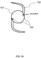
- the marks (103) show light color under natural light ( FIG. 1A ) and bright color and fluorescence under UV ( FIG. 1 B) .
- the marks (203) on the haptics (202) have relative light color under natural light ( FIG. 2A ) but the color is much brighter under stimulation, e.g., 600 nm ( FIG. 2B ).
- the quantum dot emission is within the visible spectrum, the emission can be easily seen by the human eye alone or with further aid by a microscope. If the quantum dot emission is within the NIR or SWIR spectrum, the emission can be detected by solid state Indium Gallium Arsenide (InGaAs) and/or extended range CCD or CMOS imaging cameras and imaging systems. If the quantum dot emission is within the UV spectrum, the emission can be detected by UV spectroscopy and CCD or CMOS cameras/imaging systems with UV range capabilities.
- InGaAs Indium Gallium Arsenide
- UV spectrum the quantum dot emission is within the UV spectrum
- the brightness of quantum dot emissions under "stimulation" are more than 10-20 times brighter than the "stimulated” emission from fluorescent dye. This greater brightness makes the markings with quantum dots more easily seen both directly and indirectly.
- the brighter markings may be seen through the pupil and/or by transillumination, through the iris tissue itself, as well as around the pupil by indirect reflection and/or diffraction.
- the brighter markings may be seen directly through the pupil.
- the bright quantum dot markings can be seen by transillumination, through the iris tissue itself.
- the bright light from a quantum dot mark can be seen indirectly, by reflection and/or diffraction around the edge of the pupil or opaque ocular tissue.
- quantum dots stimulated emissions are between 30,000-50,000 hours (or 3.5-6 years). Most fluorescent dyes have far shorter emission lives due to degradation, from photo bleaching or protein conjugation, which limits their functional usefulness as a marker over time. In some embodiments, therefore, the quantum dots in the lens of the present invention are able to produce stimulated emission at least 1 year, or alternatively at least 2 years, or 3 years after implantation.
- an intraocular lens using quantum dot markings will be able to be detected for many years after implantation in the eye due to the longer emission life of quantum dots.
- Quantum dot emission is greatly intensified by use of a stimulating light.
- Each quantum dot has its own optimal stimulating frequency which can lie in the UV, visible, NIR and SWIR spectrum.
- a major advantage unique to quantum dots is the broad spectral separation of stimulating frequency and emission frequency. Since ocular tissues are reflective, a broader separation of the stimulating and emitting frequency greatly enhances the signal to noise ratio. A higher signal to noise ratio reduces the chance that the marking will be undetectable or mistaken for reflected stimulating frequency.
- fluorescent dyes In contrast, fluorescent dyes generally have absorption and emission frequencies which are much closer to each other and frequently overlap one and another. Marks made with dyes have greater detection problems due to this spectral ambiguity.
- Quantum dots composed of the same core material, but with different core sizes, emit light of different wavelengths. For example, a 9 nm quantum dot will emit in the NIR spectrum, a 6 nm quantum dot will emit in the green spectrum, a smaller 4 nm quantum dot will emit in the blue spectrum, a 2 nm quantum dot will emit in the UV spectrum, and all of them can be made out of the same material.
- the size of a quantum dot therefore depends on the desired emission wavelength. They can range in size from 100 nm and smaller, with most typical applications in the range of 50 nm and smaller. In some embodiments, therefore, the quantum dots included in the marks on the intraocular lens have a size from about 2 nm to about 100 nm.
- the quantum dots have a size that is at least about 2 nm, 3 nm, 4 nm, 5 nm, 6 nm, 7 nm, 8 nm, 9 nm, 10 nm, 11 nm, 12 nm, 13 nm, 14 nm, 15 nm, 20 nm, 25 nm, 30 nm, 40 nm, 50 nm, 60 nm, 70 nm, 80 nm or 90 nm.
- the quantum dots have a size that is not greater than about 90 nm, 80 nm, 70 nm, 60 nm, 50 nm, 40 nm, 30 nm, 25 nm, 20 nm, 15 nm, 14 nm, 13 nm, 12 nm, 11 nm, 10 nm, 9 nm, 8 nm, 7 nm, 6 nm, 5 nm, 4 nm, or 3 nm.
- the quantum dots have a size between about 2 nm and about 10 nm, or between about 20 nm and about 100 nm, or between about 15 nm and about 50 nm, or between about 2 nm and about 5 nm, or between about 15 nm and about 30 nm.
- the quantum dots can be stimulated to produce an emission wavelength of between 300 nm and 2000 nm, between 750 nm and 2000 nm, between 600 nm and 749 nm, between 561 nm and 599 nm, between 500 nm and 560 nm, between 400 nm and 499 nm, or between 300 nm and 399 nm.
- Various building block materials can be used to produce quantum dots including, without limitation, Cadmium, Selenium, Tellurium, Gold, Silver, Gallium, Indium, Silicon, Germanium, Copper, Lead, Arsenic, Zinc, Iron, as well as from the Lanthanide family of elements.
- Cadmium free or heavy metal free quantum dots are particularly well suited for use in medical devices in general and intraocular lenses in particular.
- the core of a quantum dot may be encapsulated by a protective shell designed to insulate it from oxidation and to prevent leakage of the core itself.
- Zinc Sulfide and various other materials are used to produce a shell around a quantum dot.
- quantum dots offer various other coatings which can be custom designed for their unique applications.
- Functional grafting, ligands, and other surface modifiers can be used for a variety of reasons including: improved nano-dispersion, reduced agglomeration, and improved reactivity and chemical bonding with the host substrate or polymer.
- the intraocular lens of the present invention in some embodiments, comprises a central lens optic and a mark that includes quantum dots or other materials as described above.
- the mark is at a location and/or in a shape suitable to indicate the orientation or location of the lens.
- the mark has a shape that appears different when viewed from front and back.
- the mark is asymmetrical.
- the mark includes multiple signals that form a pattern which is not symmetrical. A non-limiting example of such a mark is shown in FIG. 2A-B as marks 203.
- the mark only needs to be visible.
- the marks 103 in FIG. 1A-B form a symmetric pattern but nevertheless are adequate to identify the location of the intraocular lens.
- multiple marks can be used to form a pattern.
- a pattern can include, but is not limited to, one or more of dots, line segments, arcs, squares, cross-hatching, ovals, circles, polygons with three or more sides, and so on. Some patterns can reside within other patterns. Some patterns can overlap with other patterns. Patterns can be formed using one or more types of quantum dots and/or color materials.
- multiple textures can be used in a mark or pattern, such as two, three, or more textures.
- Such textures may include, but are not limited to, smooth, hard, soft, bristled, rubbery, fuzzy, wavy, bumpy, and the like. Textures may be formed using one or more materials.
- multiple colors, multiple patterns, or multiple textures can be used, including, but not limited, two or more colors, two or more patterns, or two or more textures.
- two or more colors can be used with two or more patterns, or two or more colors can be used with two or more textures, or two or more patterns can be used with two or more textures.
- two or more colors can be used with two or more patterns and two or more textures.
- the mark is disposed on a haptic that extends from the central lens optic. As shown in FIGS. 2A-B , the marks (203) are located on the haptics (202) which are connected with the central optic (201). In some embodiments, the mark is disposed on the central lens optic (as illustrated in FIGS. 1A-B , with the marks 103 located on lens 101, not on the haptics 102).
- a sufficient number of quantum dots are present in the mark so that the mark is visible. Nevertheless, as the mark can be seen by eyes alone or by a sensor, such a requirement varies. For detection by a sensor, it is believed that an extremely small number of quantum dots (e.g., greater than 10, 50, 100, 1,000, 10,000 or more) are needed. For detection by naked eyes, the number of quantum dots required is larger and can be ascertained with methods known in the art, which can be, for instance, at least 10 6 , 10 7 , 10 8 , or 10 9 or more.
- the mark can be disposed above the surface of the lens optic or haptic (see, e.g., mark 304 above the lens or haptic 301 in FIG. 3C ).
- the mark is embedded in the lens or haptic, or a layer on the lens or haptic, as illustrated in FIG. 3A , which the mark 302 is disposed in a depression of the lens or haptic 301.
- the lens or haptic includes a plurality of small depressions or holes to hold the quantum dots of the mark.
- FIG. 3B illustrates such an embodiment, in which the quantum dots in the holes of the lens or haptic 301, to form a mark 303.
- the mark is in a layer that is also filled with a second quantum dot species characterized by a different emission wavelength, in order to create a mark which can produce two emissions either simultaneously if both species of quantum dot have the same or similar stimulating frequency, or sequentially should the quantum dots have different stimulating frequencies. Therefore, in some embodiments, the intraocular lens further includes one or more additional "marking" layer(s), containing a second species of quantum dot characterized by a different emission wavelength and/or different "stimulating wavelength".
- the layer is also filled with one or more colorants, including, but not limited to copper phthalocyanine, D&C Violet No. 2, or D&C Green No. 6 and titanium dioxide.
- one or more colorants including, but not limited to copper phthalocyanine, D&C Violet No. 2, or D&C Green No. 6 and titanium dioxide.
- Methods for using an intraocular lens of the present invention are also provided. Such methods, in one embodiment, entail detecting the mark containing the quantum dots, when they are stimulated to generate an emission. Under the guidance of the detected mark, one can then identify the orientation and/or location of the lens. Upon identification of the orientation and/or location of the lens, a user, such as a medical professional, can then carry out implantation of the lens or adjustment of the lens if the lens is already implanted.
- the emission from an intraocular lens with quantum dot mark can be used to identify the orientation of such an intraocular lens not only when the mark can be seen directly, but also when the mark is not visible to naked eyes directly, such as when the lens is implanted and covered behind the iris.
- the emission light from the quantum dots can be detected by its direct transmission through the iris tissue by virtue of the brightness of the emission light or its frequency.
- quantum dots are tuned to emit in the dark red, NIR, or SWIR wavelengths, these wavelengths can penetrate through the iris and other ocular tissues and be detected by infrared detecting equipment.
- a solid state InGaAs, CCD, or CMOS camera can be used in conjunction with a slit lamp or microscope to detect the emissions from quantum dot marks.
- the emission may still be able to either penetrate through the iris, depending on the color of patients' iris, iris thickness and other features, and/or be detected by reflection and diffraction around the pupil of the iris.
- the detection of the intraocular lens quantum dot emission light can be visualized using by a variety of means depending on the emission wavelength. Due to the brightness of quantum dot emission, if the emission wavelength is in the visible spectrum, a simple microscope can be used.
- the mark's emission level is of low intensity due to being covered by iris or other opaque ocular tissue
- a device optimized to detect the emission wavelength of the quantum dot such as InGaAs, CCD, or CMOS cameras/imaging systems with special filters and acquisition software can be employed.
- the well-defined and diverse specific emission wavelengths of quantum dots can be used singly or in combination to create a color code for a more intelligent mark.
- additional parameters of the intraocular lens can be identified, such as the magnitude of astigmatic correction.
- a mixture of different kinds of quantum dots can be used to mark the lens in order to convey the power of astigmatic correction as well as for enhanced detection when the mark is covered by the iris.
- Use of quantum dots with different emission wavelengths can create marks which can color code data about the optical correction such as the magnitude of toric correction.
- Use of a quantum dot which transmits in the NIR or SWIR spectrum would enable detection in the event of the mark being covered by the iris, when viewed with a InGaAs, CCD, or CMOS solid state cameras and/or other SWIR/NIR imaging equipment, i.e. filters and specialized software.
- a toric correcting intraocular lens with a +1.00 diopter astigmatic correction can be marked with a quantum dot with an emission of 450 nm to produce a blue color marking when stimulated.
- a toric lens with a +2.00 diopter astigmatic correction can be marked with a quantum dot of 540 nm emission to produce a green color marking when stimulated.
- a toric lens with a +3.00 diopter astigmatic correction further, can be marked with a quantum dot of 640 nm emission to produce a red color marking when stimulated.
- an additional quantum dot with a different stimulating and emitting wavelength such as one with a yellow emission, can be added to the marking layer.
- the user can first search for the whole power of astigmatic correction using a first stimulating wavelength and then search for the half power using a second stimulating wavelength. If the user detects the yellow emission, then this would confirm there was a +0.5 diopter additional power of astigmatism correction, in this case, +1.50 diopter. If no yellow emission was detected, then this would confirm the diopter power to be a whole value, in this case, +1.00 diopter.
- the present invention also provides methods of fabrication.
- the fabrication begins with providing an object, namely a intraocular lens and polymerizing at least one first monomer containing nano-sized quantum dots to form a "marking" layer that contacts the object on its surface.
- Micro-deposition MEMS equipment such as made by FUJI Dimatix Inkjet or BIODOT can be used to accurately deposit micro-drops of uncured quantum dot filled polymer to either the flat surface on the intraocular lens or to a micro-depression in the intraocular lens.
- the deposited uncured quantum dot filled polymer would then be polymerized and become integrated into the intraocular lens.
- the nano-sized semiconductor quantum dots are dispersed in (co-)monomers or uncured (co-)polymers. Such dispersions may also optionally include colorant particles. Conventional mixing techniques may be employed to prepare dispersions, including, but not limited to, closed-rotor, ultrasound, rotor-stator, colloid mill, homogenizers, and microfluidizer processors.
- Matching the type of quantum dot to the particular polymer application may also improve homogeneity and other qualities of the dispersion.
- quantum dots with particular type of functional groups attached to their outer surface may be paired with compatible co-monomers and/or functional groups.
- the starting point may be a blank disc with drilled spaces or blind holes which could be filled with uncured liquid dispersion of (co-)monomers or uncured (co-)polymers, filled with nano-sized semiconductor quantum dots, cross-linkers, and initiators.
- the uncured mixture would be polymerized, thereby integrating the marking layer into the blank disc.
- This marked disc can then be used to create a finished intraocular lens using micro-milling and micro-lathing techniques.
- Another approach would be start with an intraocular lens and deposit uncured liquid dispersion of (co-)monomers or uncured (co-)polymers, nano-sized semiconductor quantum dots, cross-linkers, and initiators, either onto the surface of the intraocular lens or into a small depressions milled into the intraocular lens.
- the deposited uncured mixture would be polymerized, thereby integrating the marking layer into the intraocular lens.
- the polymers or copolymers used may be obtained by polymerization of various monomers commonly used in the production of intraocular lenses, such as methyl methacrylate (MMA) or by copolymerization of various hydrophilic or hydrophobic comonomers, such as 2-hydroxyethyl methacrylate (HEMA), in various combinations thereof.
- MMA methyl methacrylate
- HEMA 2-hydroxyethyl methacrylate
- a copolymer with HEMA and MMA repeat units may be referred to as pHEMA-MMA.
- Any (co-)monomer or uncured copolymer that is suitable for intraocular lenses/haptics may be used, including, but not limited to, those used in producing hydrophilic, hydrophobic, and silicone-based optics/haptics.
- hydrophilic (co-)monomers examples include, but are not limited to, 2-hydroxyethylacrylate, 2-hydroxyethylmethacrylate, ethoxyethylmethacrylate, and acrylamide.
- hydrophobic (co-)monomers examples include, but are not limited to, phenylethyl methacrylate, phenylethyl acrylate, ethyl acrylate, ethyl methacrylate, glyceralmethacrylate, diacetoneacrylamide, lauryl methacrylate, butyl methacrylate, 2-ethylhexylmethacrylate, vinyl hydroxyacetate, vinyl hydroxyproprionate, vinyl hydroxybutyrate, and N-vinyl lactams.
- (co-)monomers and uncured (co-)polymers include, but are not limited to, phenylethyl acrylate, phenylethyl methacrylate, N,N-dimethylacrylamide, methacrylic acid, N-vinyl pyyolidone, tris-(trimethylsiloxysilyl)propylvinyl carbonate, N-carboxyvinyl ester, poly[dimethyldoloxy]di[silylbutanol]bis[vinyl carbamate], polyvinyl pyrrolidone, polydimethylsiloxane, and fluoroether macromers.
- Polymerization may be started using thermal initiators, such as azobisisobutyronitrile (AIBN), benzoyl peroxide, potassium persulfate, ammonium persulfate, benzophenone, methacryloyloxy benzophenone and N,N-dimethylaminoethyl methacrylate, and the like, used either as sole agents or in various combinations thereof.
- thermal initiators such as azobisisobutyronitrile (AIBN), benzoyl peroxide, potassium persulfate, ammonium persulfate, benzophenone, methacryloyloxy benzophenone and N,N-dimethylaminoethyl methacrylate, and the like, used either as sole agents or in various combinations thereof.
- AIBN azobisisobutyronitrile
- Photoinitiators may also be employed on thin films and when faster polymerization times are sought. These agents include, but are not limited to, anthraquinones, methylanthraquinones, camphoquinone tertiary amine hybrid, benzoin ethyl ether, and the like. Examples of photoinitators also include, but are not limited to, 1-[4-(2-hydroxyethyoxy)-phenyl]-2-hydroxy-2-methyl-1-propane-1-one (IRGACURE® 2959), phenyl-bis(2,4,6-trimethylbenzoylphosphine oxide) (IRGACURE® 819), and the like.
- the (co-)polymers may be subjected to inter-molecular crosslinking, to adjust their physical strength and water content.
- Crosslinking agents may include, but are not limited to, acrylate or acrylamide-based compounds, for example, ethylene glycol dimethacrylate (EGDMA), diethylene glycol bismethacrylate, butanediol diacrylate, fluoralkyl methacrylate, or N,N-methylene bis(acrylamide), and the like.
- the amount of the crosslinking agent used may be the range of 0.01-5.0 wt % based on the total weight of the monomers, and may be preferably in the range of 0.05-1.5 wt %.
- UV curing with high energy UV sources may provide cure times of, for example, a few seconds to a few minutes.
- Undesired surface morphologies such as ripples or bubbles, may be reduced or eliminated by curing the substrate in an oxygen deprived environment.
- Such an oxygen deprived environment may be provided by any suitable method, including, but not limited to, use of CO 2 gas blanketing or purging.
- Surface curing may also be reduced by such methods as, for example, simultaneously filtering both UVC and UVB wavelengths of ultraviolet light with optical filters placed between the UV lamp and the substrate.
- HEMA 2-hydroxyethyl methacrylate
- EOEMA ethoxyethyl methacrylate
- EGDMA ethylene glycol dimethacrylate
- the mixture was then processed using a Q-sonic sonicator with a % inch (i.e. 1.905 cm) solid tip probe at 40-60 % power for 1 hour.
- a water ice bath was used to maintain the temperature.
- the processed mixture was then deposited into two cylindrical depressions which were previously milled into the intraocular lens.
- the cylindrical depressions have a radius of 200 microns and a depth of 120 microns.
- the cylindrical depressions were filled with the liquid quantum dot filled copolymer.
- the intraocular lens was placed beneath a medium pressure mercury lamp, 11 inches (i.e. 27.94 cm) in length and rated at 300 watts/inch (i.e.118.11 watts/cm) (JeLight Inc., Irvine, Calif.).
- An infra-red mirror was positioned 2 inches (i.e. 5.08 cm) beneath the lamp and 5 inches (i.e. 12.7 cm) above the substrate.
- the intraocular lens was exposed to ultraviolet radiation for 2-3 minutes.
- the marked intraocular lens was hydrated overnight in saline solution in order to transform into a foldable hydrogel intraocular lens.
- the hydrated foldable intraocular lens was stimulated with 400nm light and an orange-red fluorescence was observed.
- the stimulated emission was also able to be detected with both a CCD and NIR/SWIR camera.
Landscapes
- Health & Medical Sciences (AREA)
- Public Health (AREA)
- General Health & Medical Sciences (AREA)
- Oral & Maxillofacial Surgery (AREA)
- Transplantation (AREA)
- Veterinary Medicine (AREA)
- Life Sciences & Earth Sciences (AREA)
- Ophthalmology & Optometry (AREA)
- Animal Behavior & Ethology (AREA)
- Biomedical Technology (AREA)
- Cardiology (AREA)
- Vascular Medicine (AREA)
- Heart & Thoracic Surgery (AREA)
- Engineering & Computer Science (AREA)
- Chemical & Material Sciences (AREA)
- Dermatology (AREA)
- Medicinal Chemistry (AREA)
- Epidemiology (AREA)
- Prostheses (AREA)
Abstract
Description
- The present invention relates to improved intraocular lenses for implantation in the eye and improved methods to identify their orientation during and after such implementation.
- Intraocular lenses can be implanted in the anterior chamber, at the iris plane, in the ciliary suclus space, in the posterior chamber, in the capsular bag, or at other intended spaces inside the eye. Such lenses are used in a variety of surgical procedures such as cataract surgery, clear lensectomy/vision correction, secondary implantation of an intraocular lens, phakic intraocular lens, and other vision correcting procedures.
- It is important that intraocular lenses are implanted with the correct orientation, in order for the lens optic to achieve the desired optical result and desired movement. Many intraocular lenses with advanced optical qualities, such as toric optics, require proper orientation and precise alignment to a predetermined ocular axis in order to achieve the intended visual results.
- Misalignment can occur at the time of surgery and even after surgery, in the postoperative period due to rotational movements. Misalignment can adversely affect the visual result for the patient.
- There are a number of intraocular lenses which are designed to move inside the eye, in order to provide additional optical benefits such as accommodation and enhanced voluntary focusing of vision. These intraocular lenses feature toric optical correction which require precise alignment. Misalignment of the toric correction can create optical problems.
- There are also a growing number of multi-focal intraocular lenses which are designed to correct near and intermediate vision so that bifocal or trifocal glasses are not needed. These multi-focal lenses, which can correct astigmatism, need to be aligned precisely with a predetermined axis of the eye, as well. In the same vein, there are phakic intraocular lenses designed to correct astigmatism, which likewise need to be aligned precisely with a pre-determined axis of the eye, as well.
- Currently, intraocular lens manufacturers address the issue of intraocular lens orientation by using design features such as clear round dots, clear lines, holes, notches, and tabs, to signal the proper orientation of the intraocular lens. However, these design features may be difficult to use for several reasons.
- First, these design features are small and difficult to see, because they are designed to minimize visual interference with the functions of the eyes. Further, intraocular lenses are typically made from highly transparent and colorless materials, making these subtle features even more difficult to discern. Further, when a lens is folded and rolled-up in the injector, these design features cannot be identified correctly. Likewise, when the lens is unfolded in an eye with a small pupil, it is frequently difficult or impossible to see the orientation dot, line, notch, hole or tab, because the mark may be hidden behind the iris. After the lens has unfolded, if the iris covers and obscures either a clear or colored orientation mark, the obscured mark is rendered useless.
- United States Patent Nos.
6,235,055 and8,308,800 disclose the use of a colored mark on the haptics of a toric intraocular lens that helps to mark the axis of the intraocular lens. These patents also suggest the use of bi-color marks to aid in the anterior and postior orientation of the intraocular lenses. - The current intraocular lenses also lack suitable marks indicating the magnitude for optical correction. Toric optical corrections have a magnitude known in diopters which can range from 0.25 to 6.0 diopters or greater. It would be useful to have a method of marking to reflect this information. Currently, there is not such method of marking.
- According to a first aspect of the invention, there is provided an intraocular lens comprising (a) a central lens optic and (b) a mark disposed on the central lens optic, the mark comprising a plurality of nano-sized particles of semi-conductor nanocrystals, defined as quantum dots;
wherein the intraocular lens is implanted in an area of the eye selected from the group consisting of the anterior chamber, the iris plane, the ciliary sulcus space, the posterior chamber and the capsular bag; and
wherein said mark does not contact the retinal cells of the eye. - According to a second aspect of the invention, there is provided an intraocular lens comprising (a) a central lens optic and (b) a mark disposed on a haptic projecting outwardly from the central lens optic, the mark comprising a plurality of nano-sized particles of semi-conductor nanocrystals, defined as quantum dots.
- According to a further aspect of the invention, there is provided an intraocular lens comprising (a) a central lens optic and (b) a mark disposed on the central lens optic or on a haptic projecting outwardly from the central lens optic, the mark comprising a plurality of nano-sized particles of semi-conductor nanocrystals, defined as quantum dots.
- In some embodiments, the quantum dots, when stimulated, produce an emission wavelength of between 300 nm and 2000 nm. In some embodiments, the quantum dots, when stimulated, produce an emission wavelength between 750 nm and 2000 nm. In some embodiments, the quantum dots, when stimulated, produce an emission wavelength between 600 nm and 749 nm. In some embodiments, the quantum dots, when stimulated, produce an emission wavelength of between 561 nm and 599 nm. In some embodiments, the quantum dots, when stimulated, produce an emission wavelength of between 500 nm and 560 nm. In some embodiments, the quantum dots, when stimulated, produce an emission wavelength of between 400 nm and 499 nm. In some embodiments, the quantum dots, when stimulated, produce an emission wavelength of between 300 nm and 399 nm.
- In some embodiments, the mark comprises two or more different kinds of quantum dots which have different stimulated emission wavelengths.
- In some embodiments, the mark is disposed in a pattern selected from the group consisting of dots, lines, circles, triangles, bars, letters and numbers.
- In some embodiments, the mark further comprises one or more color pigments. In some embodiments, the one or more color pigments are selected from the group consisting of copper phthalocyanine, violet dye, green dye, and titanium dioxide.
- In some embodiments, the mark is disposed on the haptic.
- According to a further aspect of the invention, there is provided a method of detecting the intraocular lens according to the present invention, comprising detecting stimulated emission of the quantum dots by a microscope and/or a CCD, CMOS and/or Indium Gallium Arsenide solid state camera.
- According to a further aspect of the invention, there is provided a method of using the intraocular lens of the present invention, the method comprising:
- identifying the orientation of the intraocular lens with stimulated emission wavelength from the quantum dots; and under guidance of the identified orientation,
- implanting the intraocular lens to the correct location and/or orientation in an eye; and/or
- adjusting the location and/or position of a previously implanted intraocular lens when needed.
- According to a further aspect of the invention, there is provided a method of using the intraocular lens of the present invention, comprising identifying parameters about the intraocular lens based on stimulated emission spectrum from the quantum dots.
- According to a further aspect of the invention, there is provided a method of preparing the intraocular lens of the present invention, comprising micro-deposition of a layer containing quantum dots filled uncured polymer to the surface of an intraocular lens and then polymerizing said marking layer.
- According to a further aspect of the invention, there is provided a method of making the intraocular lens of the present invention, comprising micro-deposition of a layer of quantum dots filled uncured polymer to a microdepression in an intraocular lens and then polymerizing said marking layer.
-
-
FIGS. 1A-1B depict an intraocular lens with two round marks containing quantum dots with a "stimulating" frequency of 400 nm and an emission frequency of 750 nm. Under exposure to outdoor sunlight and/or indoor lighting, the round marks have a slight pinkish color (shown as shaded) which is not fluorescent (FIG. 1A ). The marks have a strong reddish color (shown as dark circles) which is fluorescent in both the visible spectrum and invisible NIR spectrum (FIG. 1 B) ; and -
FIGS. 2A-2B illustrate an intraocular lens with a central lens optic, a pair of haptics and quantum dot containing marks on the haptics for indication of orientation and/or location of the lens. When viewed under natural indoor sunlight, the marks (103) show relatively light color with no fluorescence (FIG.2A ), and when viewed under stimulation, the quantum dot containing marks show much brighter color, e.g., 600 nm (FIG. 2B ); and -
FIGS. 3A-3C illustrate different ways the quantum dots or the mark containing the dots are disposed on the intraocular lens. - The present invention, in some embodiments, provides an intraocular lens comprising (a) a central lens optic and (b) a mark disposed on the central lens optic or on a haptic projecting outwardly from the central lens optic. The mark includes a plurality of nano-sized particles of semi-conductor nanocrystals, known as quantum dots. These quantum dots can emit light visible by eyes or detectable by sensors, when stimulated. The mark that includes these quantum dots, if disposed at a sufficient number to enable detection by eyes or by a sensor and at a location and/or in a shape suitable to indicate the orientation or location of the lens, can be used to identify the orientation and/or location of the lens.
- "Quantum dots" are semiconductors in the form of nano-sized crystals whose electronic characteristics are closely related to the size and shape of the individual crystal (Reed et al. (1988) Phys Rev Lett., 60 (6): 535-7). A quantum dot has its excitons confined in all three spatial dimensions.
- Quantum dots emit light due to activity of excitons or bound electrons and their electron holes. Theses emissions under natural outdoor sunlight or normal indoor light are generally of faint intensity that they are barely visible to the unaided eye. When quantum dots are exposed to a "stimulating wavelength," however, they produce a strong emission light. The "stimulated" emission wavelength can lie in the ultraviolet (UV), visible, near infrared (NIR), or shortwave infrared (SWIR) spectrum.
- Such contrast is illustrated in
FIGS. 1A-B and2A-B . For instance, the marks (103) show light color under natural light (FIG. 1A ) and bright color and fluorescence under UV (FIG. 1 B) . Likewise, the marks (203) on the haptics (202) have relative light color under natural light (FIG. 2A ) but the color is much brighter under stimulation, e.g., 600 nm (FIG. 2B ). - If the quantum dot emission is within the visible spectrum, the emission can be easily seen by the human eye alone or with further aid by a microscope. If the quantum dot emission is within the NIR or SWIR spectrum, the emission can be detected by solid state Indium Gallium Arsenide (InGaAs) and/or extended range CCD or CMOS imaging cameras and imaging systems. If the quantum dot emission is within the UV spectrum, the emission can be detected by UV spectroscopy and CCD or CMOS cameras/imaging systems with UV range capabilities.
- The brightness of quantum dot emissions under "stimulation" are more than 10-20 times brighter than the "stimulated" emission from fluorescent dye. This greater brightness makes the markings with quantum dots more easily seen both directly and indirectly. The brighter markings may be seen through the pupil and/or by transillumination, through the iris tissue itself, as well as around the pupil by indirect reflection and/or diffraction.
- The brighter markings may be seen directly through the pupil. The bright quantum dot markings can be seen by transillumination, through the iris tissue itself. The bright light from a quantum dot mark can be seen indirectly, by reflection and/or diffraction around the edge of the pupil or opaque ocular tissue.
- The longevity of quantum dots stimulated emissions are between 30,000-50,000 hours (or 3.5-6 years). Most fluorescent dyes have far shorter emission lives due to degradation, from photo bleaching or protein conjugation, which limits their functional usefulness as a marker over time. In some embodiments, therefore, the quantum dots in the lens of the present invention are able to produce stimulated emission at least 1 year, or alternatively at least 2 years, or 3 years after implantation.
- However, an intraocular lens using quantum dot markings will be able to be detected for many years after implantation in the eye due to the longer emission life of quantum dots.
- Quantum dot emission is greatly intensified by use of a stimulating light. Each quantum dot has its own optimal stimulating frequency which can lie in the UV, visible, NIR and SWIR spectrum.
- A major advantage unique to quantum dots is the broad spectral separation of stimulating frequency and emission frequency. Since ocular tissues are reflective, a broader separation of the stimulating and emitting frequency greatly enhances the signal to noise ratio. A higher signal to noise ratio reduces the chance that the marking will be undetectable or mistaken for reflected stimulating frequency.
- In contrast, fluorescent dyes generally have absorption and emission frequencies which are much closer to each other and frequently overlap one and another. Marks made with dyes have greater detection problems due to this spectral ambiguity.
- The specific emission frequency of quantum dots can be tuned by selection of core material as well as by the overall size and shape of the quantum dot. Quantum dots composed of the same core material, but with different core sizes, emit light of different wavelengths. For example, a 9 nm quantum dot will emit in the NIR spectrum, a 6 nm quantum dot will emit in the green spectrum, a smaller 4 nm quantum dot will emit in the blue spectrum, a 2 nm quantum dot will emit in the UV spectrum, and all of them can be made out of the same material.
- The size of a quantum dot therefore depends on the desired emission wavelength. They can range in size from 100 nm and smaller, with most typical applications in the range of 50 nm and smaller. In some embodiments, therefore, the quantum dots included in the marks on the intraocular lens have a size from about 2 nm to about 100 nm. In some embodiments, the quantum dots have a size that is at least about 2 nm, 3 nm, 4 nm, 5 nm, 6 nm, 7 nm, 8 nm, 9 nm, 10 nm, 11 nm, 12 nm, 13 nm, 14 nm, 15 nm, 20 nm, 25 nm, 30 nm, 40 nm, 50 nm, 60 nm, 70 nm, 80 nm or 90 nm.
- In some embodiments, the quantum dots have a size that is not greater than about 90 nm, 80 nm, 70 nm, 60 nm, 50 nm, 40 nm, 30 nm, 25 nm, 20 nm, 15 nm, 14 nm, 13 nm, 12 nm, 11 nm, 10 nm, 9 nm, 8 nm, 7 nm, 6 nm, 5 nm, 4 nm, or 3 nm. In some embodiments the quantum dots have a size between about 2 nm and about 10 nm, or between about 20 nm and about 100 nm, or between about 15 nm and about 50 nm, or between about 2 nm and about 5 nm, or between about 15 nm and about 30 nm.
- In one embodiment, the quantum dots can be stimulated to produce an emission wavelength of between 300 nm and 2000 nm, between 750 nm and 2000 nm, between 600 nm and 749 nm, between 561 nm and 599 nm, between 500 nm and 560 nm, between 400 nm and 499 nm, or between 300 nm and 399 nm.
- Various building block materials can be used to produce quantum dots including, without limitation, Cadmium, Selenium, Tellurium, Gold, Silver, Gallium, Indium, Silicon, Germanium, Copper, Lead, Arsenic, Zinc, Iron, as well as from the Lanthanide family of elements.
- There are a growing number of quantum dots which are commercially available offering a nontoxic core. Cadmium free or heavy metal free quantum dots are particularly well suited for use in medical devices in general and intraocular lenses in particular.
- The core of a quantum dot may be encapsulated by a protective shell designed to insulate it from oxidation and to prevent leakage of the core itself. Zinc Sulfide and various other materials are used to produce a shell around a quantum dot.
- Commercially available quantum dots offer various other coatings which can be custom designed for their unique applications. Functional grafting, ligands, and other surface modifiers can be used for a variety of reasons including: improved nano-dispersion, reduced agglomeration, and improved reactivity and chemical bonding with the host substrate or polymer.
- It is to be understood that, even though the present technology is described with quantum dots as the illustrative example, other types of materials can also be used to form a mark for the purpose of identifying the orientation and/or location of the lens. Such a material, in some embodiments, when stimulated under UV, NIR, IR or SWIR spectrum, generates at least 10 fold, 15 fold, or 20 fold brighter emission than under normal sunlight. Therefore, they can look relatively faint under normal use condition, without interfering with the function of the lens, but are much easier to visualize, either by eye alone or with a sensor, under UV, NIR, IR or SWIR spectrum.
- The intraocular lens of the present invention, in some embodiments, comprises a central lens optic and a mark that includes quantum dots or other materials as described above. In some embodiments, the mark is at a location and/or in a shape suitable to indicate the orientation or location of the lens.
- For identification of the orientation of an intraocular lens, it is contemplated that the mark has a shape that appears different when viewed from front and back. In one aspect, the mark is asymmetrical. In another aspect, the mark includes multiple signals that form a pattern which is not symmetrical. A non-limiting example of such a mark is shown in
FIG. 2A-B as marks 203. - For identification of the location of an intraocular lens, in another aspect, the mark only needs to be visible. For instance, the
marks 103 inFIG. 1A-B form a symmetric pattern but nevertheless are adequate to identify the location of the intraocular lens. - In some embodiments, multiple marks can be used to form a pattern. Such a pattern can include, but is not limited to, one or more of dots, line segments, arcs, squares, cross-hatching, ovals, circles, polygons with three or more sides, and so on. Some patterns can reside within other patterns. Some patterns can overlap with other patterns. Patterns can be formed using one or more types of quantum dots and/or color materials.
- In some embodiments, multiple textures can be used in a mark or pattern, such as two, three, or more textures. Such textures may include, but are not limited to, smooth, hard, soft, bristled, rubbery, fuzzy, wavy, bumpy, and the like. Textures may be formed using one or more materials.
- In some embodiments, multiple colors, multiple patterns, or multiple textures can be used, including, but not limited, two or more colors, two or more patterns, or two or more textures. In some cases, two or more colors can be used with two or more patterns, or two or more colors can be used with two or more textures, or two or more patterns can be used with two or more textures. In some cases, two or more colors can be used with two or more patterns and two or more textures.
- In some embodiments, the mark is disposed on a haptic that extends from the central lens optic. As shown in
FIGS. 2A-B , the marks (203) are located on the haptics (202) which are connected with the central optic (201). In some embodiments, the mark is disposed on the central lens optic (as illustrated inFIGS. 1A-B , with themarks 103 located onlens 101, not on the haptics 102). - In some embodiments, it is contemplated that a sufficient number of quantum dots are present in the mark so that the mark is visible. Nevertheless, as the mark can be seen by eyes alone or by a sensor, such a requirement varies. For detection by a sensor, it is believed that an extremely small number of quantum dots (e.g., greater than 10, 50, 100, 1,000, 10,000 or more) are needed. For detection by naked eyes, the number of quantum dots required is larger and can be ascertained with methods known in the art, which can be, for instance, at least 106, 107, 108, or 109 or more.
- In some embodiments, the mark can be disposed above the surface of the lens optic or haptic (see, e.g., mark 304 above the lens or haptic 301 in
FIG. 3C ). In some embodiments, the mark is embedded in the lens or haptic, or a layer on the lens or haptic, as illustrated inFIG. 3A , which themark 302 is disposed in a depression of the lens or haptic 301. In some embodiments, the lens or haptic includes a plurality of small depressions or holes to hold the quantum dots of the mark.FIG. 3B illustrates such an embodiment, in which the quantum dots in the holes of the lens or haptic 301, to form amark 303. - In some embodiments, the mark is in a layer that is also filled with a second quantum dot species characterized by a different emission wavelength, in order to create a mark which can produce two emissions either simultaneously if both species of quantum dot have the same or similar stimulating frequency, or sequentially should the quantum dots have different stimulating frequencies. Therefore, in some embodiments, the intraocular lens further includes one or more additional "marking" layer(s), containing a second species of quantum dot characterized by a different emission wavelength and/or different "stimulating wavelength".
- In some embodiments, the layer is also filled with one or more colorants, including, but not limited to copper phthalocyanine, D&C Violet No. 2, or D&C Green No. 6 and titanium dioxide.
- Methods for using an intraocular lens of the present invention are also provided. Such methods, in one embodiment, entail detecting the mark containing the quantum dots, when they are stimulated to generate an emission. Under the guidance of the detected mark, one can then identify the orientation and/or location of the lens. Upon identification of the orientation and/or location of the lens, a user, such as a medical professional, can then carry out implantation of the lens or adjustment of the lens if the lens is already implanted.
- The emission from an intraocular lens with quantum dot mark can be used to identify the orientation of such an intraocular lens not only when the mark can be seen directly, but also when the mark is not visible to naked eyes directly, such as when the lens is implanted and covered behind the iris.
- For example, when the area of the intraocular lens which contains the quantum dot orientation marking is covered by the iris, the emission light from the quantum dots can be detected by its direct transmission through the iris tissue by virtue of the brightness of the emission light or its frequency.
- If the quantum dots are tuned to emit in the dark red, NIR, or SWIR wavelengths, these wavelengths can penetrate through the iris and other ocular tissues and be detected by infrared detecting equipment. A solid state InGaAs, CCD, or CMOS camera can be used in conjunction with a slit lamp or microscope to detect the emissions from quantum dot marks.
- If the quantum dots are tuned to emit in the visible light spectrum, the emission may still be able to either penetrate through the iris, depending on the color of patients' iris, iris thickness and other features, and/or be detected by reflection and diffraction around the pupil of the iris.
- The detection of the intraocular lens quantum dot emission light can be visualized using by a variety of means depending on the emission wavelength. Due to the brightness of quantum dot emission, if the emission wavelength is in the visible spectrum, a simple microscope can be used.
- If the mark's emission level is of low intensity due to being covered by iris or other opaque ocular tissue, a device optimized to detect the emission wavelength of the quantum dot, such as InGaAs, CCD, or CMOS cameras/imaging systems with special filters and acquisition software can be employed.
- The well-defined and diverse specific emission wavelengths of quantum dots can be used singly or in combination to create a color code for a more intelligent mark. Using multiple species of quantum dots with a differing emission wavelengths and/or color pigments, additional parameters of the intraocular lens can be identified, such as the magnitude of astigmatic correction.
- A mixture of different kinds of quantum dots can be used to mark the lens in order to convey the power of astigmatic correction as well as for enhanced detection when the mark is covered by the iris. Use of quantum dots with different emission wavelengths can create marks which can color code data about the optical correction such as the magnitude of toric correction. Use of a quantum dot which transmits in the NIR or SWIR spectrum would enable detection in the event of the mark being covered by the iris, when viewed with a InGaAs, CCD, or CMOS solid state cameras and/or other SWIR/NIR imaging equipment, i.e. filters and specialized software.
- For example, a toric correcting intraocular lens with a +1.00 diopter astigmatic correction can be marked with a quantum dot with an emission of 450 nm to produce a blue color marking when stimulated. Likewise, a toric lens with a +2.00 diopter astigmatic correction can be marked with a quantum dot of 540 nm emission to produce a green color marking when stimulated. A toric lens with a +3.00 diopter astigmatic correction, further, can be marked with a quantum dot of 640 nm emission to produce a red color marking when stimulated.
- To identify whether there is an addition half diopter power, i.e., +1.50, an additional quantum dot with a different stimulating and emitting wavelength, such as one with a yellow emission, can be added to the marking layer.
- In such a case, the user can first search for the whole power of astigmatic correction using a first stimulating wavelength and then search for the half power using a second stimulating wavelength. If the user detects the yellow emission, then this would confirm there was a +0.5 diopter additional power of astigmatism correction, in this case, +1.50 diopter. If no yellow emission was detected, then this would confirm the diopter power to be a whole value, in this case, +1.00 diopter.
- The present invention also provides methods of fabrication. The fabrication, in one embodiment, begins with providing an object, namely a intraocular lens and polymerizing at least one first monomer containing nano-sized quantum dots to form a "marking" layer that contacts the object on its surface.
- Micro-deposition MEMS equipment such as made by FUJI Dimatix Inkjet or BIODOT can be used to accurately deposit micro-drops of uncured quantum dot filled polymer to either the flat surface on the intraocular lens or to a micro-depression in the intraocular lens. The deposited uncured quantum dot filled polymer would then be polymerized and become integrated into the intraocular lens.
- In some embodiments, the nano-sized semiconductor quantum dots are dispersed in (co-)monomers or uncured (co-)polymers. Such dispersions may also optionally include colorant particles. Conventional mixing techniques may be employed to prepare dispersions, including, but not limited to, closed-rotor, ultrasound, rotor-stator, colloid mill, homogenizers, and microfluidizer processors.
- Matching the type of quantum dot to the particular polymer application may also improve homogeneity and other qualities of the dispersion. For example, quantum dots with particular type of functional groups attached to their outer surface may be paired with compatible co-monomers and/or functional groups.
- For example, the starting point may be a blank disc with drilled spaces or blind holes which could be filled with uncured liquid dispersion of (co-)monomers or uncured (co-)polymers, filled with nano-sized semiconductor quantum dots, cross-linkers, and initiators. Once the spaces have been filled, the uncured mixture would be polymerized, thereby integrating the marking layer into the blank disc. This marked disc can then be used to create a finished intraocular lens using micro-milling and micro-lathing techniques.
- Another approach would be start with an intraocular lens and deposit uncured liquid dispersion of (co-)monomers or uncured (co-)polymers, nano-sized semiconductor quantum dots, cross-linkers, and initiators, either onto the surface of the intraocular lens or into a small depressions milled into the intraocular lens. The deposited uncured mixture would be polymerized, thereby integrating the marking layer into the intraocular lens.
- The polymers or copolymers used may be obtained by polymerization of various monomers commonly used in the production of intraocular lenses, such as methyl methacrylate (MMA) or by copolymerization of various hydrophilic or hydrophobic comonomers, such as 2-hydroxyethyl methacrylate (HEMA), in various combinations thereof. A copolymer with HEMA and MMA repeat units may be referred to as pHEMA-MMA.
- Any (co-)monomer or uncured copolymer that is suitable for intraocular lenses/haptics may be used, including, but not limited to, those used in producing hydrophilic, hydrophobic, and silicone-based optics/haptics.
- Examples of hydrophilic (co-)monomers include, but are not limited to, 2-hydroxyethylacrylate, 2-hydroxyethylmethacrylate, ethoxyethylmethacrylate, and acrylamide.
- Examples of hydrophobic (co-)monomers include, but are not limited to, phenylethyl methacrylate, phenylethyl acrylate, ethyl acrylate, ethyl methacrylate, glyceralmethacrylate, diacetoneacrylamide, lauryl methacrylate, butyl methacrylate, 2-ethylhexylmethacrylate, vinyl hydroxyacetate, vinyl hydroxyproprionate, vinyl hydroxybutyrate, and N-vinyl lactams.
- Other examples of (co-)monomers and uncured (co-)polymers include, but are not limited to, phenylethyl acrylate, phenylethyl methacrylate, N,N-dimethylacrylamide, methacrylic acid, N-vinyl pyyolidone, tris-(trimethylsiloxysilyl)propylvinyl carbonate, N-carboxyvinyl ester, poly[dimethyldoloxy]di[silylbutanol]bis[vinyl carbamate], polyvinyl pyrrolidone, polydimethylsiloxane, and fluoroether macromers.
- Polymerization may be started using thermal initiators, such as azobisisobutyronitrile (AIBN), benzoyl peroxide, potassium persulfate, ammonium persulfate, benzophenone, methacryloyloxy benzophenone and N,N-dimethylaminoethyl methacrylate, and the like, used either as sole agents or in various combinations thereof.
- Photoinitiators may also be employed on thin films and when faster polymerization times are sought. These agents include, but are not limited to, anthraquinones, methylanthraquinones, camphoquinone tertiary amine hybrid, benzoin ethyl ether, and the like. Examples of photoinitators also include, but are not limited to, 1-[4-(2-hydroxyethyoxy)-phenyl]-2-hydroxy-2-methyl-1-propane-1-one (IRGACURE® 2959), phenyl-bis(2,4,6-trimethylbenzoylphosphine oxide) (IRGACURE® 819), and the like.
- The (co-)polymers may be subjected to inter-molecular crosslinking, to adjust their physical strength and water content. Crosslinking agents may include, but are not limited to, acrylate or acrylamide-based compounds, for example, ethylene glycol dimethacrylate (EGDMA), diethylene glycol bismethacrylate, butanediol diacrylate, fluoralkyl methacrylate, or N,N-methylene bis(acrylamide), and the like. The amount of the crosslinking agent used may be the range of 0.01-5.0 wt % based on the total weight of the monomers, and may be preferably in the range of 0.05-1.5 wt %.
- Although various polymerization techniques may be employed, ultraviolet (UV) curing with high energy UV sources, such as, but not limited to, medium pressure mercury lamps, may provide cure times of, for example, a few seconds to a few minutes.
- Undesired surface morphologies, such as ripples or bubbles, may be reduced or eliminated by curing the substrate in an oxygen deprived environment. Such an oxygen deprived environment may be provided by any suitable method, including, but not limited to, use of CO2 gas blanketing or purging. Surface curing may also be reduced by such methods as, for example, simultaneously filtering both UVC and UVB wavelengths of ultraviolet light with optical filters placed between the UV lamp and the substrate.
- The invention will now be described with reference to the following Example:
- 7.5 mL of 2-hydroxyethyl methacrylate (HEMA), 2.5 mL ethoxyethyl methacrylate (EOEMA), and sufficient ethylene glycol dimethacrylate (EGDMA) to provide a 1.5 wt % loading were mixed together in a propeller mixer for 30 minutes. Sufficient amounts of IRGACURE® 2959 (Ciba/BASF) and IRGACURE® 819 (Ciba/BASF) photoinitiators were added to the mixture to provide 1 wt % loadings of each. The mixture was mixed for 30 minutes. Sufficient nano-sized quantum dot, with a 750 nm emission frequency and 400 m stimulation frequency, was added to the mixture to provide a 0.3 wt % loading and then stirred with a propeller mixer for 10 minutes.
- The mixture was then processed using a Q-sonic sonicator with a % inch (i.e. 1.905 cm) solid tip probe at 40-60 % power for 1 hour. A water ice bath was used to maintain the temperature.
- The processed mixture was then deposited into two cylindrical depressions which were previously milled into the intraocular lens. The cylindrical depressions have a radius of 200 microns and a depth of 120 microns. The cylindrical depressions were filled with the liquid quantum dot filled copolymer. The intraocular lens was placed beneath a medium pressure mercury lamp, 11 inches (i.e. 27.94 cm) in length and rated at 300 watts/inch (i.e.118.11 watts/cm) (JeLight Inc., Irvine, Calif.). An infra-red mirror was positioned 2 inches (i.e. 5.08 cm) beneath the lamp and 5 inches (i.e. 12.7 cm) above the substrate. The intraocular lens was exposed to ultraviolet radiation for 2-3 minutes.
- The marked intraocular lens was hydrated overnight in saline solution in order to transform into a foldable hydrogel intraocular lens.
- The hydrated foldable intraocular lens was stimulated with 400nm light and an orange-red fluorescence was observed. The stimulated emission was also able to be detected with both a CCD and NIR/SWIR camera.
Claims (13)
- An intraocular lens comprising (a) a central lens optic and (b) a mark disposed on the central lens optic, the mark comprising a plurality of nano-sized particles of semi-conductor nanocrystals, defined as quantum dots;
wherein the intraocular lens is implanted in an area of the eye selected from the group consisting of the anterior chamber, the iris plane, the ciliary sulcus space, the posterior chamber and the capsular bag; and
wherein said mark does not contact the retinal cells of the eye. - An intraocular lens comprising (a) a central lens optic and (b) a mark disposed on a haptic projecting outwardly from the central lens optic, the mark comprising a plurality of nano-sized particles of semi-conductor nanocrystals, defined as quantum dots.
- The intraocular lens according to claim 1 or claim 2, wherein the quantum dots, when stimulated, produce an emission wavelength of: between 300 nm and 2000 nm; or between 750 nm and 2000 nm; or between 600 nm and 749 nm; or between 561 nm and 599 nm; or between 500 nm and 560 nm; or between 400 nm and 499 nm; or between 300 nm and 399 nm.
- The intraocular lens according to any one of claims 1 to 3, wherein the mark comprises two or more different kinds of quantum dots which have different stimulated emission wavelengths.
- The intraocular lens according to any one of claims 1 to 4, wherein the mark further comprises one or more color pigments.
- The intraocular lens according to claim 5, wherein the one or more color pigments are selected from the group consisting of copper phthalocyanine, violet dye, green dye, and titanium dioxide.
- The intraocular lens according to claim 4, wherein the mark is disposed on the haptic.
- The intraocular lens according to any one of claims 1 to 7, wherein the mark is disposed in a pattern selected from the group consisting of dots, lines, circles, triangles, bars, letters and numbers.
- A method of detecting the intraocular lens according to any one of claims 1 to 8, comprising detecting stimulated emission of the quantum dots by a microscope and/or a CCD, CMOS and/or Indium Gallium Arsenide solid state camera.
- A method of using the intraocular lens according to any one of claims 1 to 8, the method comprising:identifying the orientation of the intraocular lens with stimulated emission wavelength from the quantum dots; and under guidance of the identified orientation,implanting the intraocular lens to the correct location and/or orientation in an eye; and/oradjusting the location and/or position of a previously implanted intraocular lens when needed.
- A method of using the intraocular lens according to any one of claims 1 to 8, comprising identifying parameters about the intraocular lens based on stimulated emission spectrum from the quantum dots.
- A method of preparing the intraocular lens according to any one of claims 1 to 8, comprising micro-deposition of a layer containing quantum dots filled uncured polymer to the surface of an intraocular lens and then polymerizing said marking layer.
- A method of making the intraocular lens according to any one of claims 1 to 8, comprising micro-deposition of a layer of quantum dots filled uncured polymer to a microdepression in an intraocular lens and then polymerizing said marking layer.
Priority Applications (1)
| Application Number | Priority Date | Filing Date | Title |
|---|---|---|---|
| EP16153978.8A EP3202369B1 (en) | 2016-02-02 | 2016-02-02 | Intraocular lenses with quantum dots |
Applications Claiming Priority (1)
| Application Number | Priority Date | Filing Date | Title |
|---|---|---|---|
| EP16153978.8A EP3202369B1 (en) | 2016-02-02 | 2016-02-02 | Intraocular lenses with quantum dots |
Publications (2)
| Publication Number | Publication Date |
|---|---|
| EP3202369A1 true EP3202369A1 (en) | 2017-08-09 |
| EP3202369B1 EP3202369B1 (en) | 2018-12-05 |
Family
ID=55300393
Family Applications (1)
| Application Number | Title | Priority Date | Filing Date |
|---|---|---|---|
| EP16153978.8A Not-in-force EP3202369B1 (en) | 2016-02-02 | 2016-02-02 | Intraocular lenses with quantum dots |
Country Status (1)
| Country | Link |
|---|---|
| EP (1) | EP3202369B1 (en) |
Cited By (3)
| Publication number | Priority date | Publication date | Assignee | Title |
|---|---|---|---|---|
| WO2020083582A1 (en) * | 2018-10-26 | 2020-04-30 | Carl Zeiss Meditec Ag | Ophthalmological implant, method for producing an ophthalmological implant, and use of a ligand for producing an ophthalmological implant |
| DE102020214126A1 (en) | 2020-11-10 | 2022-05-12 | Carl Zeiss Meditec Ag | Ophthalmic implant with digital product identification and method for its manufacture |
| DE102022105640A1 (en) | 2022-03-10 | 2023-09-14 | Carl Zeiss Meditec Ag | Ophthalmological implant with a base body which includes a preferably machine-readable product identification |
Citations (6)
| Publication number | Priority date | Publication date | Assignee | Title |
|---|---|---|---|---|
| US6235055B1 (en) | 1999-08-09 | 2001-05-22 | Milton W. Chu | Intraocular lens having colored haptics for anterior/posterior orientation, and method for implanting it |
| US20060235428A1 (en) * | 2005-04-14 | 2006-10-19 | Silvestrini Thomas A | Ocular inlay with locator |
| US20070141163A1 (en) * | 2004-01-06 | 2007-06-21 | Franco Vitaliano | Smart bio-nanoparticle elements |
| DE102008017592A1 (en) * | 2008-04-07 | 2009-10-08 | Carl Zeiss Meditec Ag | Ophthalmological implant, microscopy system and optical detection method for the detection and / or identification of an ophthalmological implant |
| DE102009037708A1 (en) * | 2009-08-17 | 2011-03-17 | Carl Zeiss Surgical Gmbh | Product for use in optical coherence tomography used in eye surgery, particularly cataract surgery and for use as e.g. intraocular lens, comprises light mediating substrate with nanoparticles |
| US8308800B2 (en) | 2010-04-09 | 2012-11-13 | Chu Milton W | Intraocular lenses with high contrast haptics, materials, and methods |
-
2016
- 2016-02-02 EP EP16153978.8A patent/EP3202369B1/en not_active Not-in-force
Patent Citations (6)
| Publication number | Priority date | Publication date | Assignee | Title |
|---|---|---|---|---|
| US6235055B1 (en) | 1999-08-09 | 2001-05-22 | Milton W. Chu | Intraocular lens having colored haptics for anterior/posterior orientation, and method for implanting it |
| US20070141163A1 (en) * | 2004-01-06 | 2007-06-21 | Franco Vitaliano | Smart bio-nanoparticle elements |
| US20060235428A1 (en) * | 2005-04-14 | 2006-10-19 | Silvestrini Thomas A | Ocular inlay with locator |
| DE102008017592A1 (en) * | 2008-04-07 | 2009-10-08 | Carl Zeiss Meditec Ag | Ophthalmological implant, microscopy system and optical detection method for the detection and / or identification of an ophthalmological implant |
| DE102009037708A1 (en) * | 2009-08-17 | 2011-03-17 | Carl Zeiss Surgical Gmbh | Product for use in optical coherence tomography used in eye surgery, particularly cataract surgery and for use as e.g. intraocular lens, comprises light mediating substrate with nanoparticles |
| US8308800B2 (en) | 2010-04-09 | 2012-11-13 | Chu Milton W | Intraocular lenses with high contrast haptics, materials, and methods |
Non-Patent Citations (2)
| Title |
|---|
| REED M A ET AL: "Observation of Discrete Electronic States in a Zero-Dimensional Semiconductor Nanostructure", PHYSICAL REVIEW LETTERS,, vol. 60, no. 6, 8 February 1988 (1988-02-08), pages 535 - 537, XP001290240 * |
| REED, PHYS REV LETT., vol. 60, no. 6, 1988, pages 535 - 7 |
Cited By (5)
| Publication number | Priority date | Publication date | Assignee | Title |
|---|---|---|---|---|
| WO2020083582A1 (en) * | 2018-10-26 | 2020-04-30 | Carl Zeiss Meditec Ag | Ophthalmological implant, method for producing an ophthalmological implant, and use of a ligand for producing an ophthalmological implant |
| CN113164248A (en) * | 2018-10-26 | 2021-07-23 | 卡尔蔡司医疗技术股份公司 | Ocular implant, method for producing an ocular implant and use of a ligand for producing an ocular implant |
| DE102020214126A1 (en) | 2020-11-10 | 2022-05-12 | Carl Zeiss Meditec Ag | Ophthalmic implant with digital product identification and method for its manufacture |
| DE102022105640A1 (en) | 2022-03-10 | 2023-09-14 | Carl Zeiss Meditec Ag | Ophthalmological implant with a base body which includes a preferably machine-readable product identification |
| WO2023170094A1 (en) | 2022-03-10 | 2023-09-14 | Carl Zeiss Meditec Ag | Ophthalmological implant comprising a machine-readable product identifier |
Also Published As
| Publication number | Publication date |
|---|---|
| EP3202369B1 (en) | 2018-12-05 |
Similar Documents
| Publication | Publication Date | Title |
|---|---|---|
| US9277988B1 (en) | Intraocular lenses with quantum dots | |
| US8308800B2 (en) | Intraocular lenses with high contrast haptics, materials, and methods | |
| EP1758521B1 (en) | Photochromic intraocular lenses and methods of making the same | |
| US8388681B2 (en) | Intraocular lenses having a visible light-selective-transmissive-region | |
| Holladay et al. | Optical performance of multifocal intraocular lenses | |
| JP5395149B2 (en) | Ophthalmic device with highly selective purple light transmissive filter | |
| US20080137030A1 (en) | Optical devices with reduced chromatic aberration | |
| RU2563495C2 (en) | Contact lens with halo effect | |
| EP3202369B1 (en) | Intraocular lenses with quantum dots | |
| EP2927734A1 (en) | Contact lens with pearlescent sclera | |
| EP1877840A2 (en) | Ophthalmic apparatuses and methods | |
| US7771470B2 (en) | Ophthalmic apparatuses and methods | |
| US10433951B2 (en) | Depth of focus and visual acuity using colorized apodization of intra-ocular lenses |
Legal Events
| Date | Code | Title | Description |
|---|---|---|---|
| PUAI | Public reference made under article 153(3) epc to a published international application that has entered the european phase |
Free format text: ORIGINAL CODE: 0009012 |
|
| STAA | Information on the status of an ep patent application or granted ep patent |
Free format text: STATUS: THE APPLICATION HAS BEEN PUBLISHED |
|
| AK | Designated contracting states |
Kind code of ref document: A1 Designated state(s): AL AT BE BG CH CY CZ DE DK EE ES FI FR GB GR HR HU IE IS IT LI LT LU LV MC MK MT NL NO PL PT RO RS SE SI SK SM TR |
|
| AX | Request for extension of the european patent |
Extension state: BA ME |
|
| STAA | Information on the status of an ep patent application or granted ep patent |
Free format text: STATUS: REQUEST FOR EXAMINATION WAS MADE |
|
| 17P | Request for examination filed |
Effective date: 20180131 |
|
| RBV | Designated contracting states (corrected) |
Designated state(s): AL AT BE BG CH CY CZ DE DK EE ES FI FR GB GR HR HU IE IS IT LI LT LU LV MC MK MT NL NO PL PT RO RS SE SI SK SM TR |
|
| STAA | Information on the status of an ep patent application or granted ep patent |
Free format text: STATUS: EXAMINATION IS IN PROGRESS |
|
| 17Q | First examination report despatched |
Effective date: 20180323 |
|
| GRAP | Despatch of communication of intention to grant a patent |
Free format text: ORIGINAL CODE: EPIDOSNIGR1 |
|
| STAA | Information on the status of an ep patent application or granted ep patent |
Free format text: STATUS: GRANT OF PATENT IS INTENDED |
|
| INTG | Intention to grant announced |
Effective date: 20180629 |
|
| GRAS | Grant fee paid |
Free format text: ORIGINAL CODE: EPIDOSNIGR3 |
|
| GRAA | (expected) grant |
Free format text: ORIGINAL CODE: 0009210 |
|
| STAA | Information on the status of an ep patent application or granted ep patent |
Free format text: STATUS: THE PATENT HAS BEEN GRANTED |
|
| AK | Designated contracting states |
Kind code of ref document: B1 Designated state(s): AL AT BE BG CH CY CZ DE DK EE ES FI FR GB GR HR HU IE IS IT LI LT LU LV MC MK MT NL NO PL PT RO RS SE SI SK SM TR |
|
| REG | Reference to a national code |
Ref country code: GB Ref legal event code: FG4D |
|
| REG | Reference to a national code |
Ref country code: CH Ref legal event code: EP |
|
| REG | Reference to a national code |
Ref country code: AT Ref legal event code: REF Ref document number: 1072119 Country of ref document: AT Kind code of ref document: T Effective date: 20181215 |
|
| REG | Reference to a national code |
Ref country code: IE Ref legal event code: FG4D |
|
| REG | Reference to a national code |
Ref country code: DE Ref legal event code: R096 Ref document number: 602016007683 Country of ref document: DE |
|
| REG | Reference to a national code |
Ref country code: NL Ref legal event code: MP Effective date: 20181205 |
|
| REG | Reference to a national code |
Ref country code: AT Ref legal event code: MK05 Ref document number: 1072119 Country of ref document: AT Kind code of ref document: T Effective date: 20181205 |
|
| REG | Reference to a national code |
Ref country code: LT Ref legal event code: MG4D |
|
| PG25 | Lapsed in a contracting state [announced via postgrant information from national office to epo] |
Ref country code: ES Free format text: LAPSE BECAUSE OF FAILURE TO SUBMIT A TRANSLATION OF THE DESCRIPTION OR TO PAY THE FEE WITHIN THE PRESCRIBED TIME-LIMIT Effective date: 20181205 Ref country code: LV Free format text: LAPSE BECAUSE OF FAILURE TO SUBMIT A TRANSLATION OF THE DESCRIPTION OR TO PAY THE FEE WITHIN THE PRESCRIBED TIME-LIMIT Effective date: 20181205 Ref country code: HR Free format text: LAPSE BECAUSE OF FAILURE TO SUBMIT A TRANSLATION OF THE DESCRIPTION OR TO PAY THE FEE WITHIN THE PRESCRIBED TIME-LIMIT Effective date: 20181205 Ref country code: BG Free format text: LAPSE BECAUSE OF FAILURE TO SUBMIT A TRANSLATION OF THE DESCRIPTION OR TO PAY THE FEE WITHIN THE PRESCRIBED TIME-LIMIT Effective date: 20190305 Ref country code: NO Free format text: LAPSE BECAUSE OF FAILURE TO SUBMIT A TRANSLATION OF THE DESCRIPTION OR TO PAY THE FEE WITHIN THE PRESCRIBED TIME-LIMIT Effective date: 20190305 Ref country code: FI Free format text: LAPSE BECAUSE OF FAILURE TO SUBMIT A TRANSLATION OF THE DESCRIPTION OR TO PAY THE FEE WITHIN THE PRESCRIBED TIME-LIMIT Effective date: 20181205 Ref country code: LT Free format text: LAPSE BECAUSE OF FAILURE TO SUBMIT A TRANSLATION OF THE DESCRIPTION OR TO PAY THE FEE WITHIN THE PRESCRIBED TIME-LIMIT Effective date: 20181205 Ref country code: AT Free format text: LAPSE BECAUSE OF FAILURE TO SUBMIT A TRANSLATION OF THE DESCRIPTION OR TO PAY THE FEE WITHIN THE PRESCRIBED TIME-LIMIT Effective date: 20181205 |
|
| PG25 | Lapsed in a contracting state [announced via postgrant information from national office to epo] |
Ref country code: SE Free format text: LAPSE BECAUSE OF FAILURE TO SUBMIT A TRANSLATION OF THE DESCRIPTION OR TO PAY THE FEE WITHIN THE PRESCRIBED TIME-LIMIT Effective date: 20181205 Ref country code: RS Free format text: LAPSE BECAUSE OF FAILURE TO SUBMIT A TRANSLATION OF THE DESCRIPTION OR TO PAY THE FEE WITHIN THE PRESCRIBED TIME-LIMIT Effective date: 20181205 Ref country code: GR Free format text: LAPSE BECAUSE OF FAILURE TO SUBMIT A TRANSLATION OF THE DESCRIPTION OR TO PAY THE FEE WITHIN THE PRESCRIBED TIME-LIMIT Effective date: 20190306 Ref country code: AL Free format text: LAPSE BECAUSE OF FAILURE TO SUBMIT A TRANSLATION OF THE DESCRIPTION OR TO PAY THE FEE WITHIN THE PRESCRIBED TIME-LIMIT Effective date: 20181205 |
|
| PG25 | Lapsed in a contracting state [announced via postgrant information from national office to epo] |
Ref country code: NL Free format text: LAPSE BECAUSE OF FAILURE TO SUBMIT A TRANSLATION OF THE DESCRIPTION OR TO PAY THE FEE WITHIN THE PRESCRIBED TIME-LIMIT Effective date: 20181205 |
|
| PG25 | Lapsed in a contracting state [announced via postgrant information from national office to epo] |
Ref country code: CZ Free format text: LAPSE BECAUSE OF FAILURE TO SUBMIT A TRANSLATION OF THE DESCRIPTION OR TO PAY THE FEE WITHIN THE PRESCRIBED TIME-LIMIT Effective date: 20181205 Ref country code: IT Free format text: LAPSE BECAUSE OF FAILURE TO SUBMIT A TRANSLATION OF THE DESCRIPTION OR TO PAY THE FEE WITHIN THE PRESCRIBED TIME-LIMIT Effective date: 20181205 Ref country code: PT Free format text: LAPSE BECAUSE OF FAILURE TO SUBMIT A TRANSLATION OF THE DESCRIPTION OR TO PAY THE FEE WITHIN THE PRESCRIBED TIME-LIMIT Effective date: 20190405 Ref country code: PL Free format text: LAPSE BECAUSE OF FAILURE TO SUBMIT A TRANSLATION OF THE DESCRIPTION OR TO PAY THE FEE WITHIN THE PRESCRIBED TIME-LIMIT Effective date: 20181205 |
|
| PG25 | Lapsed in a contracting state [announced via postgrant information from national office to epo] |
Ref country code: IS Free format text: LAPSE BECAUSE OF FAILURE TO SUBMIT A TRANSLATION OF THE DESCRIPTION OR TO PAY THE FEE WITHIN THE PRESCRIBED TIME-LIMIT Effective date: 20190405 Ref country code: SK Free format text: LAPSE BECAUSE OF FAILURE TO SUBMIT A TRANSLATION OF THE DESCRIPTION OR TO PAY THE FEE WITHIN THE PRESCRIBED TIME-LIMIT Effective date: 20181205 Ref country code: EE Free format text: LAPSE BECAUSE OF FAILURE TO SUBMIT A TRANSLATION OF THE DESCRIPTION OR TO PAY THE FEE WITHIN THE PRESCRIBED TIME-LIMIT Effective date: 20181205 Ref country code: SM Free format text: LAPSE BECAUSE OF FAILURE TO SUBMIT A TRANSLATION OF THE DESCRIPTION OR TO PAY THE FEE WITHIN THE PRESCRIBED TIME-LIMIT Effective date: 20181205 Ref country code: RO Free format text: LAPSE BECAUSE OF FAILURE TO SUBMIT A TRANSLATION OF THE DESCRIPTION OR TO PAY THE FEE WITHIN THE PRESCRIBED TIME-LIMIT Effective date: 20181205 |
|
| REG | Reference to a national code |
Ref country code: DE Ref legal event code: R097 Ref document number: 602016007683 Country of ref document: DE |
|
| REG | Reference to a national code |
Ref country code: CH Ref legal event code: PL |
|
| PLBE | No opposition filed within time limit |
Free format text: ORIGINAL CODE: 0009261 |
|
| STAA | Information on the status of an ep patent application or granted ep patent |
Free format text: STATUS: NO OPPOSITION FILED WITHIN TIME LIMIT |
|
| PG25 | Lapsed in a contracting state [announced via postgrant information from national office to epo] |
Ref country code: SI Free format text: LAPSE BECAUSE OF FAILURE TO SUBMIT A TRANSLATION OF THE DESCRIPTION OR TO PAY THE FEE WITHIN THE PRESCRIBED TIME-LIMIT Effective date: 20181205 Ref country code: MC Free format text: LAPSE BECAUSE OF FAILURE TO SUBMIT A TRANSLATION OF THE DESCRIPTION OR TO PAY THE FEE WITHIN THE PRESCRIBED TIME-LIMIT Effective date: 20181205 Ref country code: LU Free format text: LAPSE BECAUSE OF NON-PAYMENT OF DUE FEES Effective date: 20190202 Ref country code: DK Free format text: LAPSE BECAUSE OF FAILURE TO SUBMIT A TRANSLATION OF THE DESCRIPTION OR TO PAY THE FEE WITHIN THE PRESCRIBED TIME-LIMIT Effective date: 20181205 |
|
| 26N | No opposition filed |
Effective date: 20190906 |
|
| REG | Reference to a national code |
Ref country code: BE Ref legal event code: MM Effective date: 20190228 |
|
| REG | Reference to a national code |
Ref country code: IE Ref legal event code: MM4A |
|
| PG25 | Lapsed in a contracting state [announced via postgrant information from national office to epo] |
Ref country code: LI Free format text: LAPSE BECAUSE OF NON-PAYMENT OF DUE FEES Effective date: 20190228 Ref country code: CH Free format text: LAPSE BECAUSE OF NON-PAYMENT OF DUE FEES Effective date: 20190228 |
|
| PG25 | Lapsed in a contracting state [announced via postgrant information from national office to epo] |
Ref country code: IE Free format text: LAPSE BECAUSE OF NON-PAYMENT OF DUE FEES Effective date: 20190202 |
|
| PG25 | Lapsed in a contracting state [announced via postgrant information from national office to epo] |
Ref country code: FR Free format text: LAPSE BECAUSE OF NON-PAYMENT OF DUE FEES Effective date: 20190205 Ref country code: BE Free format text: LAPSE BECAUSE OF NON-PAYMENT OF DUE FEES Effective date: 20190228 |
|
| PG25 | Lapsed in a contracting state [announced via postgrant information from national office to epo] |
Ref country code: TR Free format text: LAPSE BECAUSE OF FAILURE TO SUBMIT A TRANSLATION OF THE DESCRIPTION OR TO PAY THE FEE WITHIN THE PRESCRIBED TIME-LIMIT Effective date: 20181205 |
|
| PG25 | Lapsed in a contracting state [announced via postgrant information from national office to epo] |
Ref country code: MT Free format text: LAPSE BECAUSE OF NON-PAYMENT OF DUE FEES Effective date: 20190202 |
|
| PGFP | Annual fee paid to national office [announced via postgrant information from national office to epo] |
Ref country code: DE Payment date: 20200414 Year of fee payment: 5 |
|
| GBPC | Gb: european patent ceased through non-payment of renewal fee |
Effective date: 20200202 |
|
| PG25 | Lapsed in a contracting state [announced via postgrant information from national office to epo] |
Ref country code: GB Free format text: LAPSE BECAUSE OF NON-PAYMENT OF DUE FEES Effective date: 20200202 |
|
| PG25 | Lapsed in a contracting state [announced via postgrant information from national office to epo] |
Ref country code: CY Free format text: LAPSE BECAUSE OF FAILURE TO SUBMIT A TRANSLATION OF THE DESCRIPTION OR TO PAY THE FEE WITHIN THE PRESCRIBED TIME-LIMIT Effective date: 20181205 |
|
| PG25 | Lapsed in a contracting state [announced via postgrant information from national office to epo] |
Ref country code: HU Free format text: LAPSE BECAUSE OF FAILURE TO SUBMIT A TRANSLATION OF THE DESCRIPTION OR TO PAY THE FEE WITHIN THE PRESCRIBED TIME-LIMIT; INVALID AB INITIO Effective date: 20160202 |
|
| REG | Reference to a national code |
Ref country code: DE Ref legal event code: R119 Ref document number: 602016007683 Country of ref document: DE |
|
| PG25 | Lapsed in a contracting state [announced via postgrant information from national office to epo] |
Ref country code: DE Free format text: LAPSE BECAUSE OF NON-PAYMENT OF DUE FEES Effective date: 20210901 |
|
| PG25 | Lapsed in a contracting state [announced via postgrant information from national office to epo] |
Ref country code: MK Free format text: LAPSE BECAUSE OF FAILURE TO SUBMIT A TRANSLATION OF THE DESCRIPTION OR TO PAY THE FEE WITHIN THE PRESCRIBED TIME-LIMIT Effective date: 20181205 |