EP3202302A1 - Endoscope provided with bending operation mechanism - Google Patents
Endoscope provided with bending operation mechanism Download PDFInfo
- Publication number
- EP3202302A1 EP3202302A1 EP15847560.8A EP15847560A EP3202302A1 EP 3202302 A1 EP3202302 A1 EP 3202302A1 EP 15847560 A EP15847560 A EP 15847560A EP 3202302 A1 EP3202302 A1 EP 3202302A1
- Authority
- EP
- European Patent Office
- Prior art keywords
- section
- watertight
- frame section
- endoscope
- bending operation
- Prior art date
- Legal status (The legal status is an assumption and is not a legal conclusion. Google has not performed a legal analysis and makes no representation as to the accuracy of the status listed.)
- Withdrawn
Links
- 238000005452 bending Methods 0.000 title claims abstract description 55
- 230000007246 mechanism Effects 0.000 title claims abstract description 53
- 230000002093 peripheral effect Effects 0.000 claims description 25
- 238000003780 insertion Methods 0.000 claims description 15
- 230000037431 insertion Effects 0.000 claims description 15
- 238000005192 partition Methods 0.000 claims description 12
- 238000010586 diagram Methods 0.000 description 13
- 230000002265 prevention Effects 0.000 description 9
- 230000004048 modification Effects 0.000 description 7
- 238000012986 modification Methods 0.000 description 7
- 229940113601 irrigation solution Drugs 0.000 description 4
- 239000007788 liquid Substances 0.000 description 4
- 239000000853 adhesive Substances 0.000 description 2
- 230000001070 adhesive effect Effects 0.000 description 2
- 230000008901 benefit Effects 0.000 description 2
- 239000008280 blood Substances 0.000 description 2
- 210000004369 blood Anatomy 0.000 description 2
- 230000003247 decreasing effect Effects 0.000 description 2
- 230000002401 inhibitory effect Effects 0.000 description 2
- 238000000034 method Methods 0.000 description 2
- 210000000056 organ Anatomy 0.000 description 2
- 230000008569 process Effects 0.000 description 2
- 229910001220 stainless steel Inorganic materials 0.000 description 2
- 239000010935 stainless steel Substances 0.000 description 2
- 230000001954 sterilising effect Effects 0.000 description 2
- 238000004659 sterilization and disinfection Methods 0.000 description 2
- 238000013459 approach Methods 0.000 description 1
- 238000004891 communication Methods 0.000 description 1
- 239000013013 elastic material Substances 0.000 description 1
- 238000005286 illumination Methods 0.000 description 1
- 239000000463 material Substances 0.000 description 1
- 239000002184 metal Substances 0.000 description 1
- 239000007769 metal material Substances 0.000 description 1
- 239000011347 resin Substances 0.000 description 1
- 229920005989 resin Polymers 0.000 description 1
- 230000000630 rising effect Effects 0.000 description 1
- XLYOFNOQVPJJNP-UHFFFAOYSA-N water Substances O XLYOFNOQVPJJNP-UHFFFAOYSA-N 0.000 description 1
Images



Classifications
-
- A—HUMAN NECESSITIES
- A61—MEDICAL OR VETERINARY SCIENCE; HYGIENE
- A61B—DIAGNOSIS; SURGERY; IDENTIFICATION
- A61B1/00—Instruments for performing medical examinations of the interior of cavities or tubes of the body by visual or photographical inspection, e.g. endoscopes; Illuminating arrangements therefor
- A61B1/005—Flexible endoscopes
- A61B1/0051—Flexible endoscopes with controlled bending of insertion part
- A61B1/0052—Constructional details of control elements, e.g. handles
-
- A—HUMAN NECESSITIES
- A61—MEDICAL OR VETERINARY SCIENCE; HYGIENE
- A61B—DIAGNOSIS; SURGERY; IDENTIFICATION
- A61B1/00—Instruments for performing medical examinations of the interior of cavities or tubes of the body by visual or photographical inspection, e.g. endoscopes; Illuminating arrangements therefor
- A61B1/00002—Operational features of endoscopes
- A61B1/00039—Operational features of endoscopes provided with input arrangements for the user
- A61B1/00042—Operational features of endoscopes provided with input arrangements for the user for mechanical operation
-
- A—HUMAN NECESSITIES
- A61—MEDICAL OR VETERINARY SCIENCE; HYGIENE
- A61B—DIAGNOSIS; SURGERY; IDENTIFICATION
- A61B1/00—Instruments for performing medical examinations of the interior of cavities or tubes of the body by visual or photographical inspection, e.g. endoscopes; Illuminating arrangements therefor
- A61B1/00064—Constructional details of the endoscope body
- A61B1/00066—Proximal part of endoscope body, e.g. handles
-
- A—HUMAN NECESSITIES
- A61—MEDICAL OR VETERINARY SCIENCE; HYGIENE
- A61B—DIAGNOSIS; SURGERY; IDENTIFICATION
- A61B1/00—Instruments for performing medical examinations of the interior of cavities or tubes of the body by visual or photographical inspection, e.g. endoscopes; Illuminating arrangements therefor
- A61B1/005—Flexible endoscopes
- A61B1/0051—Flexible endoscopes with controlled bending of insertion part
- A61B1/0057—Constructional details of force transmission elements, e.g. control wires
-
- A—HUMAN NECESSITIES
- A61—MEDICAL OR VETERINARY SCIENCE; HYGIENE
- A61B—DIAGNOSIS; SURGERY; IDENTIFICATION
- A61B34/00—Computer-aided surgery; Manipulators or robots specially adapted for use in surgery
- A61B34/70—Manipulators specially adapted for use in surgery
- A61B34/74—Manipulators with manual electric input means
-
- G—PHYSICS
- G02—OPTICS
- G02B—OPTICAL ELEMENTS, SYSTEMS OR APPARATUS
- G02B23/00—Telescopes, e.g. binoculars; Periscopes; Instruments for viewing the inside of hollow bodies; Viewfinders; Optical aiming or sighting devices
- G02B23/24—Instruments or systems for viewing the inside of hollow bodies, e.g. fibrescopes
-
- G—PHYSICS
- G02—OPTICS
- G02B—OPTICAL ELEMENTS, SYSTEMS OR APPARATUS
- G02B23/00—Telescopes, e.g. binoculars; Periscopes; Instruments for viewing the inside of hollow bodies; Viewfinders; Optical aiming or sighting devices
- G02B23/24—Instruments or systems for viewing the inside of hollow bodies, e.g. fibrescopes
- G02B23/2476—Non-optical details, e.g. housings, mountings, supports
-
- A—HUMAN NECESSITIES
- A61—MEDICAL OR VETERINARY SCIENCE; HYGIENE
- A61B—DIAGNOSIS; SURGERY; IDENTIFICATION
- A61B34/00—Computer-aided surgery; Manipulators or robots specially adapted for use in surgery
- A61B34/70—Manipulators specially adapted for use in surgery
- A61B34/74—Manipulators with manual electric input means
- A61B2034/742—Joysticks
-
- A—HUMAN NECESSITIES
- A61—MEDICAL OR VETERINARY SCIENCE; HYGIENE
- A61M—DEVICES FOR INTRODUCING MEDIA INTO, OR ONTO, THE BODY; DEVICES FOR TRANSDUCING BODY MEDIA OR FOR TAKING MEDIA FROM THE BODY; DEVICES FOR PRODUCING OR ENDING SLEEP OR STUPOR
- A61M25/00—Catheters; Hollow probes
- A61M25/01—Introducing, guiding, advancing, emplacing or holding catheters
- A61M25/0105—Steering means as part of the catheter or advancing means; Markers for positioning
- A61M25/0133—Tip steering devices
- A61M25/0136—Handles therefor
Definitions
- the present invention relates to a bending operation mechanism having a watertight structure and an endoscope including the bending operation mechanism.
- endoscopes have widely been used in the medical field and the industrial field to examine and treat a cavity and a hollow organ of the body.
- These endoscopes include a thin elongated insertion section to be inserted into the cavity and hollow organ of the body.
- a flexible scope bent in accordance with the bending state of an insertion path and a rigid scope used chiefly for operations and the like are known.
- the flexible scope includes a bending section at its distal end, and the bending section can freely be bent in a desired direction in accordance with a user's hand operation.
- Patent Literature 1 Jpn. Pat. Appln. KOKAI Publication No. 2009-89955
- a conventional endoscope an endoscope is known in which a user tilts a joystick-type operating lever provided on an operating section toward an arbitrary direction to pull an operating wire and render a bending section in a desired bending state.
- an insertion section used in a body cavity has a watertight structure to prevent water drops and blood from entering the body cavity, and an operating section, which is formed integrally with the insertion section as one unit, needs a reasonable watertight structure to irrigate and sterilize the operating section after it is used.
- Patent Literature 2 Jpn. Pat. Appln. KOKAI Publication No. 2004-321612 discloses an endoscope in which a joystick lever portion is covered with an elastic cover member (e.g. rubber cover or a rubber boot) which is fitted into a central hole in a watertight manner and the peripheral edge portion of the boot is pressed and fixed on an operating section exterior member by a substantially ring-shaped fixing member.
- an elastic cover member e.g. rubber cover or a rubber boot
- Patent Literature2 Jpn. Pat. Appln. KOKAI Publication No. 2004-321612
- the peripheral edge portion of the rubber boot is pressed by the inner diameter side of an engage ring that is the fixing member of the rubber boot, a plurality of O-shaped rings are fitted on the outer diameter side thereof to achieve a watertight structure, and a pressing member and a screw fixing portion to fix a screw are provided together in the radial direction between them. Since this structure inhibits the operating section from decreasing in diameter size and increases the number of parts for use, it will be a factor in inhibiting low costs.
- Patent Literature 2 Jpn. Pat. Appln. KOKAI Publication No. 2004-321612 , furthermore, when the engaging ring is replaced with a simply shaped one, it is assumed that the screw is obviated, a screw groove is formed in the engage ring itself which is attached, and a screw groove is formed in a casing (the main body of the operating section) to which the engaging ring is attached. In this case, it is usually considered that the peripheral edge of the rubber boot is pressed and applied onto the inner diameter side of the engage ring and the O-shaped rings are arranged on the outer periphery thereof such that the operating section has a watertight structure.
- the inside of the rubber boot in the tilt range of the joystick lever serves as a movable space in the main body of the operating section.
- pressure such as an irrigation solution
- the rubber boot is entangled in the movable space and caught in a member such as a stopper. If the joystick lever moves in this state, the rubber boot can be damaged.
- an object of the present invention to provide an endoscope which prevents an elastic cover member of a joystick-type operating section from being twisted when the elastic cover member is fixed on the main body of the operating section and prevents the elastic cover member from being entangled when a joystick lever is operated.
- an endoscope having a bending operation mechanism, the endoscope including an operating section to give an instruction to bend a bending section provided on a distal end side of an elongated insertion section, the endoscope comprising: an operating lever having one end as a fulcrum and the other end, the other end of the operating lever being tiltable in all directions centering around the fulcrum; a frame section including the fulcrum and an opening in which the operating lever is placed and a frame wall portion is formed at a tip of the opening, the frame section including a locking section on an outer peripheral side thereof; a tilt regulation member placed in the frame section and having a first hole portion to regulate a tilt range of the operating lever; a boot section including a watertight fixing portion attached to an outer surface of the frame wall portion to cover the opening of the frame section in a watertight manner by causing the operating lever to pass through the opening; a first fixing member engaged with the locking section of the frame section and locked unrotat
- FIG. 1 shows an example of a conceptual structure of an endoscope 1 according to a first embodiment.
- the endoscope 1 of the present embodiment chiefly includes an elongated flexible insertion section 2 to be inserted into a body cavity, an operating section 3 connected to the proximal end of the insertion section 2, a light guide connector 4 connected to a light source device (not shown), and a video connector 5 connected to a video system center (not shown).
- the operating section 3 and the light guide connector 4 are connected through a flexible cable 6 as a universal cord, and the light guide connector 4 and the video connector 5 are connected through a communication cable 7.
- the insertion section 2 includes a distal end portion 11 cylindrically formed chiefly of a metallic member such as stainless steel, a bending section 12, and a rigid tube 13 of a metal tube such as stainless steel, which are connected in sequence from the distal end of the insertion section.
- the end face of the rigid tube 13 to be inserted into a body cavity is provided with an irradiation window for illumination light and an image-pickup section, and the insertion section 2 includes a signal cable for video signals, a light guide and the like.
- the operating section 3 includes a bending operation mechanism 60 that is a bending operation section to operate the bending section 12 remotely and various switches 16 to perform a variety of functions by the foregoing light source device and video system center.
- the bending operation mechanism 60 is provided at the proximal end portion of the operating section 3 (on the back side opposed to the insertion section 2).
- one side of the operating section 3 on which the insertion section 2 is provided will be referred to as a distal end side
- the other side thereof on which the bending operation mechanism 60 is provided will be referred to as a proximal end side.
- a grip 10 from which the flexible cable 6 extends is provided to extend from the lateral side of the proximal end portion.
- the endoscope 1 is so configured that the bending section 12 is freely bent in four directions of up, down, right and left directions and the combination of these directions (referred to as all directions hereinafter) by the tilt operation of a joystick lever 50 of the bending operation mechanism 60.
- the bending operation mechanism 60 of the present embodiment will be described below.
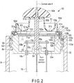
- FIG. 2 is a diagram showing a cross-sectional structure of the bending operation mechanism
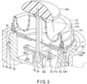
- FIG. 3 is a perspective diagram showing a cross-sectional structure of the bending operation mechanism when viewed from the oblique direction
- FIG. 4 is a diagram showing a cross-sectional structure of a portion to which a boot fixing ring and a pressing ring are added.
- the bending operation mechanism 60 of the present embodiment is placed on the proximal end side of a housing 8 [operating section exterior member] of the operating section 3. Needless to say, the position of the placement is not limited to the proximal end side, but it can be provided on the side surface of the housing 8 or a projecting portion formed to project from the side surface unless it impairs the operability.
- the bending operation mechanism 60 includes the joystick lever 50 [operating lever], a rubber boot [boot section] 51 that is a cover member formed of an elastic material, a frame section 52 serving as a mechanism casing, and a wire pulling section 53 to bend the bending section.
- the frame section 52 is formed of a metallic material or a rigid resin material and shaped like a cylinder with a bottom (shaped like a cup), and an opening 52d is formed in the top of the frame section 52 and covered with the rubber boot 51.
- a projecting portion 52r having a plurality of screw holes on its outer surface is formed on the entire outer surface of the frame section 52, and a projecting portion 8a overlapping the projecting portion 52r is formed on the entire inner surface of the housing 8.
- screw holes corresponding to the screw holes of the projecting portion 52r are formed in the projecting portion 8a, too, and these screw holes are screwed by screws 59 to fix the frame section 52 in the housing 8. Since, furthermore, the projecting portion 52r and the projecting portion 8a are bonded using the screws by interposing a seal member between them, the watertight structure can be achieved between the housing 8 and the frame section 52. In this case, the O-shaped ring used in a pressing ring 103, described later, is unnecessary.
- the rubber boot 51 is shaped like a cap covering the circumference of the opening with the distal end portion of the joystick lever 50 exposed outwardly.
- the shape of the circumference of the rubber boot 51 matches that of the opening of the frame section 52.
- the circumference of the rubber boot 51 is circular.
- the rubber boot 51 has such a section that the center of the boot is raised like a trapezoid to form a central part 51b having a flat surface, and the circumference of the boot rises substantially vertically from a peripheral edge portion 51a [watertight fixing portion] to have an annular, wavy, concave shape (roundish concave portion 51c) between the peripheral edge portion 51a and the central part 51b as shown in FIG. 4 .
- the waveform (the roundness of a semicircle) of a roundish convex portion 51d which leads to the roundish concave portion 51c from a portion of the edge side wall is formed small, and the roundness (the roundness of a semicircle) of the bottom of the roundish concave portion 51c is formed larger than the roundish convex portion 51d.
- the rubber boot 51 prevents the joystick lever 50 from increasing in its operating force by increasing the waveform of the tilt range of the joystick lever 50 and decreasing the waveform of the outer periphery side, thereby improving the ability to hold a shape against a crush from the outer periphery side. If, furthermore, the roundness of the bottom of the roundish concave portion 51c is increased, an irrigation solution flows and circulates smoothly and, for example, dirt can be removed more easily.
- a hole through which the joystick lever 50 passes is formed in the center of the flat central part 51b.
- the hole and the joystick lever 50 are bonded in a watertight manner to prevent a liquid (e.g. blood and irrigation solution) from going into the frame section 52.
- the peripheral edge portion 51a of the rubber boot 51 is thick and the section thereof is circular to have the function of an O-shaped ring to achieve a watertight structure.
- the peripheral edge portion 51a is placed in a groove 52i formed by a boot fixing ring 102, described later, and a frame wall portion 52g and crushed by pressure of both the walls, thus achieving a watertight structure in the frame section 52.
- the joystick lever 50 includes a finger hook portion 50a for hooking an operator's finger, a rod 50b and a spherical portion 54.
- the rod 50b is substantially cylindrical and tapered from its proximal end portion placed in the frame section 52 toward its distal end portion exposed outwardly, and the proximal end side is provided with a step 50c to lock the wire pulling section 53.
- the finger hook portion 50a is semicircular and attached to the distal end portion of the rod 50b exposed outwardly.
- the spherical portion 54 is formed to lead to the step 50c at the proximal end of the rod 50b.
- the spherical portion 54 is fitted turnably in a sphere receiving portion 52b provided substantially in the center of the bottom surface 52a of the frame section 52 to hold the rod 50b movably.
- a ball joint mechanism including the spherical portion 54 and the sphere receiving portion 52b is employed.
- the central position of turn by the spherical portion 54 and sphere receiving portion 52b of the ball joint mechanism will be referred to as a fulcrum (or a fulcrum position).
- the wire pulling section 53 is fitted from the distal end side of the rod 50b and bonded and fixed to the step 50c of the proximal end in an abutting state.
- the movable mechanism is not limited to the ball joint mechanism, but for example, a publicly known mechanism such as a mechanism pivotally supported by two shafts intersecting at right angles can be employed.
- FIG. 2 of the present embodiment shows a structure including an entanglement prevention mechanism of a third embodiment described later; however, in the first embodiment, the entanglement prevention mechanism can be provided or need not be done. If the entanglement prevention mechanism is provided, the third embodiment will bring about a greater advantage.
- the wire pulling section 53 includes four pulling arm portions 53b shaped like a cross (see FIG. 3 ) such that the rod 50b is fitted into the intersection of the pulling portions, and a locking hole 53c is formed close to an end portion of each of the pulling arm portions 53b.
- a hole is formed in a position opposed to the locking hole 53c in parallel to the central axis A when the angle is 0°, and a coil pipe 19b is fitted and fixed into the hole.
- a locking member 19a which is provided at one end of a bending operation wire 19 guided through the coil pipe 19b, is locked into the locking hole 53c.
- the locking member is locked, the bending operation wire 19 extending to the bending section 12 is pulled and loosened in accordance with a tilt of the pulling arm portions 53b.
- the bending section 12 is bent in all directions if a plurality of bending pieces (not shown) provided inside are turned in accordance with a state in which each of the bending operation wires 19 is pulled and loosened.
- the frame wall portion 52g is formed to protrude from the top of the outer surface of the frame section 52, and a brim portion is formed at the distal end portion of the frame wall portion to extend toward the outer surface.
- the brim portion serves to prevent the peripheral edge portion 51a of the rubber boot 51 from being removed from the groove 52i formed by a boot fixing ring 102 and frame wall portion 52g, which will be described later.
- a fitting portion 52j having a side surface and a flat surface is provided to lower from a flat surface corresponding to the undersurface of the groove 52i of the frame wall portion 52g through a step.
- the boot fixing ring 102 is fitted to the fitting portion 52j.
- the fitting portion 52j has a diameter larger than that of the groove 52i, and at least one positioning hole 52m [concave portion] is formed in the flat surface of the fitting portion 52j.
- the positioning hole 52m is not limited to a cylindrical hole but may be a square hole or a notched groove 52n notched from the outer peripheral side, as described later with reference to FIG. 8 .
- a male screw 52k is formed on the side surface continuing downward from the flat surface of the fitting portion 52j through the step.
- the pressing ring 103 described later, is screwed to the male screw 52k.
- the boot fixing ring 102 [first fixing member] is shaped like a cylinder having a crank-shaped section, and a brim is formed at the end of the boot fixing ring 102 to overhang the inner peripheral side to prevent the peripheral edge portion 51a from being removed from the groove 52i as described above. Furthermore, a flange portion 102b is formed to overhang the outer peripheral side at the lower end of the boot fixing ring 102. The flange portion 102b includes a hook 102a [convex portion] fitted into the corresponding positioning hole 52m.
- the boot fixing ring 102 is externally fitted to the fitting portion 52j from above such that the hook 102a is fitted into the hole 52m. If the hook 102a is fitted into the hole 52m and positioned, the fitting state is held to prevent the boot fixing ring 102 from turning when the pressing ring 103 described later is screwed. If the boot fixing ring 102 is so fitted, the peripheral edge portion 51a of the rubber boot 51 fitted between the inner surface of the boot fixing ring 102 and the undersurface of the groove 52i or the outer surface of the frame wall portion 52g is crushed.
- the peripheral edge portion 51a serves as an O-shaped ring in a watertight state and prevents a liquid from going into the frame section 52 from outside.
- the pressing ring 103 [second fixing member] is screwed to the male screw 52K to retain a watertight state by the boot fixing ring 102.
- the pressing ring 103 is shaped like a cylinder, overhangs the upper side of the inner surface, and includes two brim portions 103e and 103f used as groove walls to press the boot fixing ring 102.
- the brim portions 103e and 103f are separated from each other, and an interval between them is used as a groove 103b in which an O-shaped ring 104 is fitted.
- This O-shaped ring 104 prevents moisture, which enters from the screwed portion of the pressing ring 103 and the frame section 52 through a gap between the boot fixing ring 102 and the pressing ring 103 from outside, from going into the housing 8. With this screwing, the O-shaped ring 104 presses the upper part of the boot fixing ring 102 elastically in the radial direction, and the brim portion 103f supports the O-shaped ring 104 and presses and fixes the flange portion 102b on the fitting portion 52j located below.
- the pressing ring 103 presses the boot fixing ring 102 from its outer surface side, and the O-shaped ring 104 causes a watertight state between the pressing ring 103 and the boot fixing ring 102.
- the pressing ring 103 overhangs the lower side of the outer surface and includes brim portions 103g and 103h to be supported against the frame section 52, and an interval between them is used as a groove 103c in which an O-shaped ring 105 is fitted.
- a female screw 103a screwed to the male screw 52k is formed in the inner surface corresponding to the underside of the brim portions 103g and 103h.
- the O-shaped ring 105 presses the housing 8 to retain a watertight state between the housing 8 and the pressing ring 103 and prevents a liquid from going into the housing 8 from outside.
- the bending operation mechanism of the present embodiment has a watertight structure including the boot fixing ring 102 for achieving watertightness, which does not turn, and the pressing ring 103 to fix the boot fixing ring 102 on the frame section 52.
- this watertight structure when the pressing ring 103 is screwed and fixed to the frame section 52, it turns to exert its force on the boot fixing ring 102 via the O-shaped ring 104 in the turn direction. Then, the hook 102a of the boot fixing ring 102 is engaged with the hole 52m of the frame section 52 and thus the boot fixing ring 102 is prevented from turning. Thus, even though the pressing ring 103 is screwed, no rotation force is applied to the peripheral edge portion 51a.
- the bending operation mechanism of the present embodiment has a watertight structure to prevent a liquid from going into the operation section, and prevents a twist from being caused between the peripheral edge portion 51a and central part 51b of the rubber boot 51, a nonuniform force is not applied to the joystick lever 50 due to a deformation of the rubber boot 51, with the result that a smooth lever tilt operation can be performed with an equal degree of force.
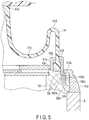
- FIG. 5 shows a structure in which the housing 8 and the frame section 52 are directly bonded and fixed as a modification to the first embodiment.
- the foregoing first embodiment has a structure in which the housing 8 and the frame section 52 are rendered watertight by the O-shaped ring 105, whereas the modification has a structure in which the housing 8 and the frame section 52 are directly bonded and rendered watertight.
- the same structural elements as those of the foregoing first embodiment are denoted by the same reference sign and their detailed descriptions are omitted.
- the present modification includes a pressing ring 110 excluding the O-shaped ring 104 of the pressing ring 103.
- the pressing ring 110 includes a fixing portion 110a to fix the flange portion 102b under the outer periphery portion of the boot fixing ring 102 when the pressing ring 110 is screwed to the frame section 52.
- a fixing portion 110b prevents the flange portion 102b from rising and thus prevents the hook 102a formed on the undersurface of the flange portion 102b from being detached from the positioning hole 52m.
- a female screw 110c screwed to the male screw 52k formed on the outer surface of the frame section 52 is formed on the inner surface side of the pressing ring 110.
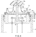
- FIG. 6 is a cross-sectional diagram of a bending operation mechanism 60 of the second embodiment.
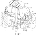
- FIG. 7 is a perspective diagram of a section of a partly-enlarged component of the bending operation mechanism 60 of the second embodiment.
- the same structural elements as those of the foregoing first embodiment are denoted by the same reference sign and their detailed descriptions are omitted.
- the present embodiment differs from the first embodiment in the structure to prevent the boot fixing ring 102 from rotating with respect to the frame sections 52.
- at least one positioning pin 106 is fitted on the flat surface of the fitting portion 52j.
- a hole 102c fitted to the positioning pin 106 is formed in the flange portion 102b under the outer periphery portion of the boot fixing ring 102.
- the positioning pin 106 is fitted into the hole 102c and the boot fixing ring 102 is externally fitted to the fitting portion 52j from above.
- the pressing ring 103 is screwed and fixed to the frame section 52, it turns to exert its force on the boot fixing ring 102 via the O-shaped ring 104 in the turn direction.
- the hole 102c of the boot fixing ring 102 is fitted to the positioning pin 106 of the frame section 52 and thus the boot fixing ring 102 is prevented from turning.
- the boot fixing ring 102 to achieve watertightness for the peripheral edge portion 51a of the rubber boot 51 is prevented from rotating and its fixing state is held by fitting the positioning pin 106 into the hole 102c when the pressing ring 103 is screwed.
- FIG. 8 is a cross-sectional view of a bending operation mechanism 60 of the third embodiment including an entanglement prevention mechanism.
- the same structural elements as those of the foregoing first embodiment are denoted by the same reference sign and their detailed descriptions are omitted. Since FIG. 2 also shows a structure including an entanglement prevention mechanism, the third embodiment will be described with reference to FIGS. 2 and 8 .
- the opening 52d of the frame section 52 includes a hole through which the rod 50b passes, and a tilt regulation member 71, a partition plate 100 and a pressing plate 101 are stacked one on another with a gap therebetween.
- a male screw is formed on the periphery of each of the tilt regulation member 71 and pressing plate 101 and screwed into the opening 52d.
- the partition plate 100 is so configured to move in the gap between the tilt regulation member 71 and pressing plate 101 in accordance with the tilt operation of the rod 50b.
- two steps of an upper step 52p and a lower step 52q are formed on the inner surface from the opening 52d toward the bottom.
- a female screw 52e is formed on the inner surface side of the frame wall portion 52g, and the upper step 52p is formed below the female screw.
- the surface of the upper step 52p corresponds to the placement surface of the pressing plate 101.
- a female screw 52f is formed on the inner surface of the lower step 52q from the upper step 52p, and the surface of the lower step 52q corresponds to the placement surface of the tilt regulation member 71.
- the tilt regulation member 71 is screwed to the female screw 52f and fixed on the surface of the lower step 52q. It is desirable to bond them partly with an adhesive or the like in order to prevent the screw from loosening thereafter.
- a hole 71a is opened to set a tilt angle (tilt range) of the joystick lever 50.
- the partition plate 100 is placed on the tilt regulation member 71.
- a hole 100a whose diameter is slightly larger than that of the rod 50b is opened.
- the diameter of the hole 100a is set such that a gap is formed between the hole 100a and the rod 50b to prevent the hole 100a from contacting the rod 50b passing through the hole 100a to perform a tilt operation.
- the partition plate 100 does not abut on the inner surface of the frame section 52 but has a size not to expose the hole 71a.
- the partition plate 100 may have irregularities of very small dots and patterns on its front and rear surfaces to decrease the area of contact between the tilt regulation member 71 and the pressing plate 101, lower the frictional resistance, and reduce a load applied to the tilt operation.
- the pressing plate 101 is screwed to the female screw 52e and fixed on the surface of the upper step 52p. It is desirable to bond them partly with an adhesive or the like in order to prevent the screw from loosening thereafter. In this fixing, the pressing plate 101 does not contact the partition plate 100 with a gap therebetween or they contact each other to such a degree that only a slight load is applied.
- the pressing plate 101 has a hole 101a having such a diameter that the rod 50b does not abut on the hole 71a even though the joystick lever 50 is tilted to the limit of tilt. These holes 71a, 100a and 101a are arranged such that their centers coincide with one another or they are arranged concentrically when the tilt angle of the joystick lever 50 is 0° (central axis A).
- the foregoing rubber boot 51 is attached to cover the opening 52d of the frame section 52.
- the tilt regulation member 71 is fixed on the inner side of the opening 52d of the frame section 52 and the pressing plate 101 is placed on the outer side with the partition plate 100 therebetween.
- the operating section is sterilized together with the insertion section after the endoscope is used, pressure is applied to the operating section by an irrigation solution or the like in the sterilization process and focused on the roundish concave portion 51c of the rubber boot 51 in terms of its shape if the endoscope has a bending operation mechanism.
- the edge sidewall falls inwardly, and the roundish concave portion 51c extends and approaches or contacts the frame section 52.
- the partition plate 100 to prevent the rubber boot 51 from going inside is provided on the top surface of the tilt regulation member 71.
- the entanglement prevention mechanism of the present embodiment when an external pressure is applied to the being mechanism or a negative pressure is caused in the operating section, even though the boot section made of an elastic member is extended by the pressure, the rubber boot 51 is not drawn into the frame section 52. Thus, the rubber boot is not entangled in the movable space of the operating section or it is not damaged.
- a structure including the entanglement prevention mechanism is shown, but the entanglement prevention mechanism can be used alone or in combination.
Landscapes
- Health & Medical Sciences (AREA)
- Life Sciences & Earth Sciences (AREA)
- Surgery (AREA)
- Physics & Mathematics (AREA)
- Engineering & Computer Science (AREA)
- Optics & Photonics (AREA)
- Public Health (AREA)
- Heart & Thoracic Surgery (AREA)
- Medical Informatics (AREA)
- Molecular Biology (AREA)
- Animal Behavior & Ethology (AREA)
- General Health & Medical Sciences (AREA)
- Biomedical Technology (AREA)
- Veterinary Medicine (AREA)
- Nuclear Medicine, Radiotherapy & Molecular Imaging (AREA)
- Biophysics (AREA)
- Pathology (AREA)
- Radiology & Medical Imaging (AREA)
- Astronomy & Astrophysics (AREA)
- General Physics & Mathematics (AREA)
- Mechanical Engineering (AREA)
- Robotics (AREA)
- Endoscopes (AREA)
- Instruments For Viewing The Inside Of Hollow Bodies (AREA)
Abstract
Description
- The present invention relates to a bending operation mechanism having a watertight structure and an endoscope including the bending operation mechanism.
- Recently, endoscopes have widely been used in the medical field and the industrial field to examine and treat a cavity and a hollow organ of the body. These endoscopes include a thin elongated insertion section to be inserted into the cavity and hollow organ of the body. As the insertion section, a flexible scope bent in accordance with the bending state of an insertion path and a rigid scope used chiefly for operations and the like are known. The flexible scope includes a bending section at its distal end, and the bending section can freely be bent in a desired direction in accordance with a user's hand operation.
- As disclosed in, for example, Patent Literature 1:
Jpn. Pat. Appln. KOKAI Publication No. 2009-89955 - In medical endoscopes, an insertion section used in a body cavity has a watertight structure to prevent water drops and blood from entering the body cavity, and an operating section, which is formed integrally with the insertion section as one unit, needs a reasonable watertight structure to irrigate and sterilize the operating section after it is used.
- The conventional endoscope including a joystick lever type operating section is so configured that even though a joystick lever is tilted to any position within a movable range of the joystick lever, the water-tightness between the joystick lever and the exterior member is always secured and the lever operation is not inhibited. For example, Patent Literature 2:
Jpn. Pat. Appln. KOKAI Publication No. 2004-321612 - In the structure disclosed in Patent Literature2:
Jpn. Pat. Appln. KOKAI Publication No. 2004-321612 - In the structure of Patent Literature 2:
Jpn. Pat. Appln. KOKAI Publication No. 2004-321612 - Since a grasping member is attached to the distal end of the joystick lever exposed from the central hole, the rubber boot and the joystick lever are attached in a watertight manner and the boot as a whole is difficult to turn.
- When the engage ring is added and screwed on the casing, turn-direction force is exerted on the peripheral edge of the rubber boot and the O-shaped rings. This turn-direction force causes a twist between the central part and peripheral edge of the fixed rubber boot. This twist deforms the rubber boot and the deformation always applies nonuniform force to the joystick lever. Thus, when the lever is operated, the degree of force required for the operation varies from tilt direction to tilt direction.
- Furthermore, the inside of the rubber boot in the tilt range of the joystick lever serves as a movable space in the main body of the operating section. For example, when a sterilization process is performed, pressure such as an irrigation solution is applied from outside, and the rubber boot is entangled in the movable space and caught in a member such as a stopper. If the joystick lever moves in this state, the rubber boot can be damaged.
- Accordingly, it is an object of the present invention to provide an endoscope which prevents an elastic cover member of a joystick-type operating section from being twisted when the elastic cover member is fixed on the main body of the operating section and prevents the elastic cover member from being entangled when a joystick lever is operated. In addition, it is an object to provide a small-sized light bending operation mechanism having a watertight structure and an endoscope having the bending operation mechanism.
- According to the present invention, it is an object to provide an endoscope which prevents an elastic cover member of a joystick-type operating section from being twisted when the elastic cover member is fixed on the main body of the operating section and prevents the elastic cover member from being caught when a joystick lever is operated. In addition, it is an object to provide a small-sized light bending operation mechanism having a watertight structure and an endoscope having the bending operation mechanism.
- According to an embodiment of the present invention, there is provided an endoscope having a bending operation mechanism, the endoscope including an operating section to give an instruction to bend a bending section provided on a distal end side of an elongated insertion section, the endoscope comprising: an operating lever having one end as a fulcrum and the other end, the other end of the operating lever being tiltable in all directions centering around the fulcrum; a frame section including the fulcrum and an opening in which the operating lever is placed and a frame wall portion is formed at a tip of the opening, the frame section including a locking section on an outer peripheral side thereof; a tilt regulation member placed in the frame section and having a first hole portion to regulate a tilt range of the operating lever; a boot section including a watertight fixing portion attached to an outer surface of the frame wall portion to cover the opening of the frame section in a watertight manner by causing the operating lever to pass through the opening; a first fixing member engaged with the locking section of the frame section and locked unrotatably in the watertight fixing portion of the boot section to press the watertight fixing portion from an outer periphery side such that the watertight fixing portion is made watertight; and a second fixing member screwed with the frame section to fix the first fixing member on the frame section.
-
-
FIG. 1 is a diagram showing an example of a conceptual structure of an endoscope according to a first embodiment. -
FIG. 2 is a diagram showing a cross-sectional structure of a bending operation mechanism of the first embodiment. -
FIG. 3 is a perspective diagram showing a cross-sectional structure of the bending operation mechanism of the first embodiment when viewed from the oblique direction. -
FIG. 4 is a diagram showing a cross-sectional structure of a portion to which a boot fixing ring and a pressing ring are added. -
FIG. 5 is a diagram showing a cross-sectional structure of a bending operation mechanism of a modification to the first embodiment. -
FIG. 6 is a diagram showing a cross-sectional structure of a bending operation mechanism of a second embodiment. -
FIG. 7 is a perspective diagram showing a cross-sectional structure of the bending operation mechanism of the second embodiment when viewed from the oblique direction. -
FIG. 8 is a diagram showing a cross-sectional structure of a bending operation mechanism of a third embodiment. - Embodiments of the present invention will be described in detail below with reference to the drawings.
-
FIG. 1 shows an example of a conceptual structure of an endoscope 1 according to a first embodiment. - The endoscope 1 of the present embodiment chiefly includes an elongated
flexible insertion section 2 to be inserted into a body cavity, anoperating section 3 connected to the proximal end of theinsertion section 2, alight guide connector 4 connected to a light source device (not shown), and avideo connector 5 connected to a video system center (not shown). In the endoscope 1, theoperating section 3 and thelight guide connector 4 are connected through aflexible cable 6 as a universal cord, and thelight guide connector 4 and thevideo connector 5 are connected through a communication cable 7. - The
insertion section 2 includes adistal end portion 11 cylindrically formed chiefly of a metallic member such as stainless steel, abending section 12, and arigid tube 13 of a metal tube such as stainless steel, which are connected in sequence from the distal end of the insertion section. The end face of therigid tube 13 to be inserted into a body cavity is provided with an irradiation window for illumination light and an image-pickup section, and theinsertion section 2 includes a signal cable for video signals, a light guide and the like. - The
operating section 3 includes abending operation mechanism 60 that is a bending operation section to operate thebending section 12 remotely andvarious switches 16 to perform a variety of functions by the foregoing light source device and video system center. Thebending operation mechanism 60 is provided at the proximal end portion of the operating section 3 (on the back side opposed to the insertion section 2). In the following descriptions, one side of theoperating section 3 on which theinsertion section 2 is provided will be referred to as a distal end side, and the other side thereof on which thebending operation mechanism 60 is provided will be referred to as a proximal end side. Moreover, agrip 10 from which theflexible cable 6 extends is provided to extend from the lateral side of the proximal end portion. The endoscope 1 is so configured that thebending section 12 is freely bent in four directions of up, down, right and left directions and the combination of these directions (referred to as all directions hereinafter) by the tilt operation of ajoystick lever 50 of thebending operation mechanism 60. - The
bending operation mechanism 60 of the present embodiment will be described below. -
FIG. 2 is a diagram showing a cross-sectional structure of the bending operation mechanism,FIG. 3 is a perspective diagram showing a cross-sectional structure of the bending operation mechanism when viewed from the oblique direction, andFIG. 4 is a diagram showing a cross-sectional structure of a portion to which a boot fixing ring and a pressing ring are added. - The bending
operation mechanism 60 of the present embodiment is placed on the proximal end side of a housing 8 [operating section exterior member] of theoperating section 3. Needless to say, the position of the placement is not limited to the proximal end side, but it can be provided on the side surface of thehousing 8 or a projecting portion formed to project from the side surface unless it impairs the operability. - The bending
operation mechanism 60 includes the joystick lever 50 [operating lever], a rubber boot [boot section] 51 that is a cover member formed of an elastic material, aframe section 52 serving as a mechanism casing, and awire pulling section 53 to bend the bending section. Of these sections, theframe section 52 is formed of a metallic material or a rigid resin material and shaped like a cylinder with a bottom (shaped like a cup), and anopening 52d is formed in the top of theframe section 52 and covered with therubber boot 51. - A projecting
portion 52r having a plurality of screw holes on its outer surface is formed on the entire outer surface of theframe section 52, and a projectingportion 8a overlapping the projectingportion 52r is formed on the entire inner surface of thehousing 8. When theframe section 52 is fitted into thehousing 8 such that the projectingportion 52r and the projectingportion 8a overlap each other, screw holes corresponding to the screw holes of the projectingportion 52r are formed in the projectingportion 8a, too, and these screw holes are screwed byscrews 59 to fix theframe section 52 in thehousing 8. Since, furthermore, the projectingportion 52r and the projectingportion 8a are bonded using the screws by interposing a seal member between them, the watertight structure can be achieved between thehousing 8 and theframe section 52. In this case, the O-shaped ring used in apressing ring 103, described later, is unnecessary. - The
rubber boot 51 is shaped like a cap covering the circumference of the opening with the distal end portion of thejoystick lever 50 exposed outwardly. The shape of the circumference of therubber boot 51 matches that of the opening of theframe section 52. Here, the circumference of therubber boot 51 is circular. Therubber boot 51 has such a section that the center of the boot is raised like a trapezoid to form acentral part 51b having a flat surface, and the circumference of the boot rises substantially vertically from aperipheral edge portion 51a [watertight fixing portion] to have an annular, wavy, concave shape (roundishconcave portion 51c) between theperipheral edge portion 51a and thecentral part 51b as shown inFIG. 4 . Particularly, the waveform (the roundness of a semicircle) of a roundishconvex portion 51d which leads to the roundishconcave portion 51c from a portion of the edge side wall is formed small, and the roundness (the roundness of a semicircle) of the bottom of the roundishconcave portion 51c is formed larger than the roundishconvex portion 51d. - As described above, the
rubber boot 51 prevents thejoystick lever 50 from increasing in its operating force by increasing the waveform of the tilt range of thejoystick lever 50 and decreasing the waveform of the outer periphery side, thereby improving the ability to hold a shape against a crush from the outer periphery side. If, furthermore, the roundness of the bottom of the roundishconcave portion 51c is increased, an irrigation solution flows and circulates smoothly and, for example, dirt can be removed more easily. - In the center of the flat
central part 51b, a hole through which thejoystick lever 50 passes is formed. The hole and thejoystick lever 50 are bonded in a watertight manner to prevent a liquid (e.g. blood and irrigation solution) from going into theframe section 52. Furthermore, theperipheral edge portion 51a of therubber boot 51 is thick and the section thereof is circular to have the function of an O-shaped ring to achieve a watertight structure. Theperipheral edge portion 51a is placed in agroove 52i formed by aboot fixing ring 102, described later, and aframe wall portion 52g and crushed by pressure of both the walls, thus achieving a watertight structure in theframe section 52. - The
joystick lever 50 includes afinger hook portion 50a for hooking an operator's finger, arod 50b and aspherical portion 54. Therod 50b is substantially cylindrical and tapered from its proximal end portion placed in theframe section 52 toward its distal end portion exposed outwardly, and the proximal end side is provided with astep 50c to lock thewire pulling section 53. Thefinger hook portion 50a is semicircular and attached to the distal end portion of therod 50b exposed outwardly. Furthermore, thespherical portion 54 is formed to lead to thestep 50c at the proximal end of therod 50b. - The
spherical portion 54 is fitted turnably in asphere receiving portion 52b provided substantially in the center of thebottom surface 52a of theframe section 52 to hold therod 50b movably. In the present embodiment, as a movable mechanism of thejoystick lever 50, a ball joint mechanism including thespherical portion 54 and thesphere receiving portion 52b is employed. In the following description, the central position of turn by thespherical portion 54 andsphere receiving portion 52b of the ball joint mechanism will be referred to as a fulcrum (or a fulcrum position). Moreover, thewire pulling section 53 is fitted from the distal end side of therod 50b and bonded and fixed to thestep 50c of the proximal end in an abutting state. The movable mechanism is not limited to the ball joint mechanism, but for example, a publicly known mechanism such as a mechanism pivotally supported by two shafts intersecting at right angles can be employed. - If, in the above structure, the
joystick lever 50 is tilted, thewire pulling section 53 is shaken in arbitrary directions (all directions) centering around the fulcrum when the central axis A of therod 50b is in a vertical direction (angle of 0°). Atilt regulation member 71 is placed in theopening 52d of theframe section 52 to set an inclination angle range (or an inclination range) of thejoystick lever 50 based on the diameter of ahole 71a.FIG. 2 of the present embodiment shows a structure including an entanglement prevention mechanism of a third embodiment described later; however, in the first embodiment, the entanglement prevention mechanism can be provided or need not be done. If the entanglement prevention mechanism is provided, the third embodiment will bring about a greater advantage. - The
wire pulling section 53 includes four pullingarm portions 53b shaped like a cross (seeFIG. 3 ) such that therod 50b is fitted into the intersection of the pulling portions, and alocking hole 53c is formed close to an end portion of each of the pullingarm portions 53b. On thebottom surface 52a of theframe section 52, a hole is formed in a position opposed to thelocking hole 53c in parallel to the central axis A when the angle is 0°, and acoil pipe 19b is fitted and fixed into the hole. - A locking
member 19a, which is provided at one end of abending operation wire 19 guided through thecoil pipe 19b, is locked into the lockinghole 53c. When the locking member is locked, the bendingoperation wire 19 extending to thebending section 12 is pulled and loosened in accordance with a tilt of the pullingarm portions 53b. The bendingsection 12 is bent in all directions if a plurality of bending pieces (not shown) provided inside are turned in accordance with a state in which each of thebending operation wires 19 is pulled and loosened. - The
frame wall portion 52g is formed to protrude from the top of the outer surface of theframe section 52, and a brim portion is formed at the distal end portion of the frame wall portion to extend toward the outer surface. The brim portion serves to prevent theperipheral edge portion 51a of therubber boot 51 from being removed from thegroove 52i formed by aboot fixing ring 102 andframe wall portion 52g, which will be described later. - As shown in
FIG. 4 , afitting portion 52j having a side surface and a flat surface is provided to lower from a flat surface corresponding to the undersurface of thegroove 52i of theframe wall portion 52g through a step. Theboot fixing ring 102 is fitted to thefitting portion 52j. Thefitting portion 52j has a diameter larger than that of thegroove 52i, and at least onepositioning hole 52m [concave portion] is formed in the flat surface of thefitting portion 52j. Thepositioning hole 52m is not limited to a cylindrical hole but may be a square hole or a notchedgroove 52n notched from the outer peripheral side, as described later with reference toFIG. 8 . - Furthermore, a
male screw 52k is formed on the side surface continuing downward from the flat surface of thefitting portion 52j through the step. Thepressing ring 103, described later, is screwed to themale screw 52k. - The boot fixing ring 102 [first fixing member] is shaped like a cylinder having a crank-shaped section, and a brim is formed at the end of the
boot fixing ring 102 to overhang the inner peripheral side to prevent theperipheral edge portion 51a from being removed from thegroove 52i as described above. Furthermore, aflange portion 102b is formed to overhang the outer peripheral side at the lower end of theboot fixing ring 102. Theflange portion 102b includes ahook 102a [convex portion] fitted into thecorresponding positioning hole 52m. - As shown in
FIG. 3 , after theperipheral edge portion 51a of therubber boot 51 is attached to theframe wall portion 52g, theboot fixing ring 102 is externally fitted to thefitting portion 52j from above such that thehook 102a is fitted into thehole 52m. If thehook 102a is fitted into thehole 52m and positioned, the fitting state is held to prevent theboot fixing ring 102 from turning when thepressing ring 103 described later is screwed. If theboot fixing ring 102 is so fitted, theperipheral edge portion 51a of therubber boot 51 fitted between the inner surface of theboot fixing ring 102 and the undersurface of thegroove 52i or the outer surface of theframe wall portion 52g is crushed. Theperipheral edge portion 51a serves as an O-shaped ring in a watertight state and prevents a liquid from going into theframe section 52 from outside. - Furthermore, as shown in
FIG. 4 , the pressing ring 103 [second fixing member] is screwed to the male screw 52K to retain a watertight state by theboot fixing ring 102. Thepressing ring 103 is shaped like a cylinder, overhangs the upper side of the inner surface, and includes twobrim portions boot fixing ring 102. Thebrim portions groove 103b in which an O-shapedring 104 is fitted. This O-shapedring 104 prevents moisture, which enters from the screwed portion of thepressing ring 103 and theframe section 52 through a gap between theboot fixing ring 102 and thepressing ring 103 from outside, from going into thehousing 8. With this screwing, the O-shapedring 104 presses the upper part of theboot fixing ring 102 elastically in the radial direction, and thebrim portion 103f supports the O-shapedring 104 and presses and fixes theflange portion 102b on thefitting portion 52j located below. - Furthermore, the
pressing ring 103 presses theboot fixing ring 102 from its outer surface side, and the O-shapedring 104 causes a watertight state between thepressing ring 103 and theboot fixing ring 102. Thepressing ring 103 overhangs the lower side of the outer surface and includesbrim portions frame section 52, and an interval between them is used as agroove 103c in which an O-shapedring 105 is fitted. Afemale screw 103a screwed to themale screw 52k is formed in the inner surface corresponding to the underside of thebrim portions ring 105 presses thehousing 8 to retain a watertight state between thehousing 8 and thepressing ring 103 and prevents a liquid from going into thehousing 8 from outside. - As described above, the bending operation mechanism of the present embodiment has a watertight structure including the
boot fixing ring 102 for achieving watertightness, which does not turn, and thepressing ring 103 to fix theboot fixing ring 102 on theframe section 52. In this watertight structure, when thepressing ring 103 is screwed and fixed to theframe section 52, it turns to exert its force on theboot fixing ring 102 via the O-shapedring 104 in the turn direction. Then, thehook 102a of theboot fixing ring 102 is engaged with thehole 52m of theframe section 52 and thus theboot fixing ring 102 is prevented from turning. Thus, even though thepressing ring 103 is screwed, no rotation force is applied to theperipheral edge portion 51a. - Therefore, since the bending operation mechanism of the present embodiment has a watertight structure to prevent a liquid from going into the operation section, and prevents a twist from being caused between the
peripheral edge portion 51a andcentral part 51b of therubber boot 51, a nonuniform force is not applied to thejoystick lever 50 due to a deformation of therubber boot 51, with the result that a smooth lever tilt operation can be performed with an equal degree of force. -
FIG. 5 shows a structure in which thehousing 8 and theframe section 52 are directly bonded and fixed as a modification to the first embodiment. The foregoing first embodiment has a structure in which thehousing 8 and theframe section 52 are rendered watertight by the O-shapedring 105, whereas the modification has a structure in which thehousing 8 and theframe section 52 are directly bonded and rendered watertight. In the present modification, the same structural elements as those of the foregoing first embodiment are denoted by the same reference sign and their detailed descriptions are omitted. - The present modification includes a
pressing ring 110 excluding the O-shapedring 104 of thepressing ring 103. As shown inFIG. 5 , thepressing ring 110 includes a fixingportion 110a to fix theflange portion 102b under the outer periphery portion of theboot fixing ring 102 when thepressing ring 110 is screwed to theframe section 52. A fixing portion 110b prevents theflange portion 102b from rising and thus prevents thehook 102a formed on the undersurface of theflange portion 102b from being detached from thepositioning hole 52m. - A
female screw 110c screwed to themale screw 52k formed on the outer surface of theframe section 52 is formed on the inner surface side of thepressing ring 110. - In this modification, too, the advantage that is equivalent to that of the foregoing first embodiment can be obtained. Since, furthermore, neither of the O-shaped
rings pressing ring 103 is required, the structure is simplified and the number of parts can be reduced. - A second embodiment will be described below.
FIG. 6 is a cross-sectional diagram of abending operation mechanism 60 of the second embodiment.FIG. 7 is a perspective diagram of a section of a partly-enlarged component of thebending operation mechanism 60 of the second embodiment. The same structural elements as those of the foregoing first embodiment are denoted by the same reference sign and their detailed descriptions are omitted. - The present embodiment differs from the first embodiment in the structure to prevent the
boot fixing ring 102 from rotating with respect to theframe sections 52. As shown inFIG. 6 , at least onepositioning pin 106 is fitted on the flat surface of thefitting portion 52j. Ahole 102c fitted to thepositioning pin 106 is formed in theflange portion 102b under the outer periphery portion of theboot fixing ring 102. - As shown in
FIG. 7 , after theperipheral edge portion 51a of therubber boot 51 is fitted into thegroove 52i, thepositioning pin 106 is fitted into thehole 102c and theboot fixing ring 102 is externally fitted to thefitting portion 52j from above. When thepressing ring 103 is screwed and fixed to theframe section 52, it turns to exert its force on theboot fixing ring 102 via the O-shapedring 104 in the turn direction. Then, thehole 102c of theboot fixing ring 102 is fitted to thepositioning pin 106 of theframe section 52 and thus theboot fixing ring 102 is prevented from turning. - In the above-described watertight structure of the present embodiment, the
boot fixing ring 102 to achieve watertightness for theperipheral edge portion 51a of therubber boot 51 is prevented from rotating and its fixing state is held by fitting thepositioning pin 106 into thehole 102c when thepressing ring 103 is screwed. - Thus, when the
pressing ring 103 is screwed, no rotation force is applied to theperipheral edge portion 51a. Therefore, no twist is caused between theperipheral edge portion 51a andcentral part 51b of therubber boot 51 or no nonuniform force is not applied to thejoystick lever 50 due to a deformation of therubber boot 51, with the result that a smooth lever tilt operation can be performed with the same degree of force. - A third embodiment will be described below.
FIG. 8 is a cross-sectional view of abending operation mechanism 60 of the third embodiment including an entanglement prevention mechanism. The same structural elements as those of the foregoing first embodiment are denoted by the same reference sign and their detailed descriptions are omitted. SinceFIG. 2 also shows a structure including an entanglement prevention mechanism, the third embodiment will be described with reference toFIGS. 2 and8 . - The
opening 52d of theframe section 52 includes a hole through which therod 50b passes, and atilt regulation member 71, apartition plate 100 and apressing plate 101 are stacked one on another with a gap therebetween. A male screw is formed on the periphery of each of thetilt regulation member 71 andpressing plate 101 and screwed into theopening 52d. Thepartition plate 100 is so configured to move in the gap between thetilt regulation member 71 andpressing plate 101 in accordance with the tilt operation of therod 50b. - As shown in
FIG. 8 , two steps of anupper step 52p and alower step 52q are formed on the inner surface from the opening 52d toward the bottom. Afemale screw 52e is formed on the inner surface side of theframe wall portion 52g, and theupper step 52p is formed below the female screw. The surface of theupper step 52p corresponds to the placement surface of thepressing plate 101. Moreover, afemale screw 52f is formed on the inner surface of thelower step 52q from theupper step 52p, and the surface of thelower step 52q corresponds to the placement surface of thetilt regulation member 71. - The
tilt regulation member 71 is screwed to thefemale screw 52f and fixed on the surface of thelower step 52q. It is desirable to bond them partly with an adhesive or the like in order to prevent the screw from loosening thereafter. In thetilt regulation member 71, ahole 71a is opened to set a tilt angle (tilt range) of thejoystick lever 50. - The
partition plate 100 is placed on thetilt regulation member 71. In thepartition plate 100, ahole 100a whose diameter is slightly larger than that of therod 50b is opened. The diameter of thehole 100a is set such that a gap is formed between thehole 100a and therod 50b to prevent thehole 100a from contacting therod 50b passing through thehole 100a to perform a tilt operation. Furthermore, when thejoystick lever 50 is tilted to the limit of tilt, thepartition plate 100 does not abut on the inner surface of theframe section 52 but has a size not to expose thehole 71a. Furthermore, thepartition plate 100 may have irregularities of very small dots and patterns on its front and rear surfaces to decrease the area of contact between thetilt regulation member 71 and thepressing plate 101, lower the frictional resistance, and reduce a load applied to the tilt operation. - The
pressing plate 101 is screwed to thefemale screw 52e and fixed on the surface of theupper step 52p. It is desirable to bond them partly with an adhesive or the like in order to prevent the screw from loosening thereafter. In this fixing, thepressing plate 101 does not contact thepartition plate 100 with a gap therebetween or they contact each other to such a degree that only a slight load is applied. Thepressing plate 101 has ahole 101a having such a diameter that therod 50b does not abut on thehole 71a even though thejoystick lever 50 is tilted to the limit of tilt. Theseholes joystick lever 50 is 0° (central axis A). The foregoingrubber boot 51 is attached to cover theopening 52d of theframe section 52. - In the present embodiment, the
tilt regulation member 71 is fixed on the inner side of theopening 52d of theframe section 52 and thepressing plate 101 is placed on the outer side with thepartition plate 100 therebetween. - As described in the foregoing item of "the objects of the invention," since the operating section is sterilized together with the insertion section after the endoscope is used, pressure is applied to the operating section by an irrigation solution or the like in the sterilization process and focused on the roundish
concave portion 51c of therubber boot 51 in terms of its shape if the endoscope has a bending operation mechanism. Thus, the edge sidewall falls inwardly, and the roundishconcave portion 51c extends and approaches or contacts theframe section 52. As an entanglement prevention mechanism, thepartition plate 100 to prevent therubber boot 51 from going inside is provided on the top surface of thetilt regulation member 71. - According to the entanglement prevention mechanism of the present embodiment, when an external pressure is applied to the being mechanism or a negative pressure is caused in the operating section, even though the boot section made of an elastic member is extended by the pressure, the
rubber boot 51 is not drawn into theframe section 52. Thus, the rubber boot is not entangled in the movable space of the operating section or it is not damaged. In the drawings of the foregoing first and second embodiments, a structure including the entanglement prevention mechanism is shown, but the entanglement prevention mechanism can be used alone or in combination.
Claims (4)
- An endoscope having a bending operation mechanism, the endoscope including an operating section to give an instruction to bend a bending section provided on a distal end side of an elongated insertion section, the endoscope characterized by comprising:an operating lever having one end as a fulcrum and the other end, the other end of the operating lever being tiltable in all directions centering around the fulcrum;a frame section including the fulcrum and an opening in which the operating lever is placed and a frame wall portion is formed at a tip of the opening, the frame section including a locking section on an outer peripheral side thereof;a tilt regulation member placed in the frame section and having a first hole portion to regulate a tilt range of the operating lever;a boot section including a watertight fixing portion attached to an outer surface of the frame wall portion to cover the opening of the frame section in a watertight manner by causing the operating lever to pass through the opening;a first fixing member engaged with the locking section of the frame section and locked unrotatably in the watertight fixing portion of the boot section to press the watertight fixing portion from an outer periphery side such that the watertight fixing portion is made watertight; anda second fixing member screwed with the frame section to fix the first fixing member on the frame section.
- The endoscope having a bending operation mechanism according to claim 1, characterized in that the second fixing member further includes:a first elastic member attached to an inner surface to press an outer periphery of the first fixing member elastically and maintain watertightness; anda second elastic member attached to an outer surface to press an exterior member of the operating section elastically and maintain watertightness.
- The endoscope having a bending operation mechanism according to claim 1, characterized in that the frame section and an exterior member of the operating section are bonded to each other in a watertight manner.
- The endoscope having a bending operation mechanism according to claim 1, characterized in that the bending operation mechanism further includes:a partition member placed movably on the tilt regulation member and moved following a tilt operation of the operating lever to cover the first hole portion to prevent the first hole from being exposed; anda pressing member fixed in the opening above the partition member such that the partition member is caught between the pressing member and the tilt regulation member, the pressing member having a second hole portion whose diameter is larger than that of the first hole portion.
Applications Claiming Priority (2)
| Application Number | Priority Date | Filing Date | Title |
|---|---|---|---|
| JP2014204884 | 2014-10-03 | ||
| PCT/JP2015/075897 WO2016052147A1 (en) | 2014-10-03 | 2015-09-11 | Endoscope provided with bending operation mechanism |
Publications (2)
| Publication Number | Publication Date |
|---|---|
| EP3202302A1 true EP3202302A1 (en) | 2017-08-09 |
| EP3202302A4 EP3202302A4 (en) | 2018-07-11 |
Family
ID=55630190
Family Applications (1)
| Application Number | Title | Priority Date | Filing Date |
|---|---|---|---|
| EP15847560.8A Withdrawn EP3202302A4 (en) | 2014-10-03 | 2015-09-11 | Endoscope provided with bending operation mechanism |
Country Status (5)
| Country | Link |
|---|---|
| US (1) | US10537230B2 (en) |
| EP (1) | EP3202302A4 (en) |
| JP (1) | JP6053999B2 (en) |
| CN (1) | CN106714648B (en) |
| WO (1) | WO2016052147A1 (en) |
Cited By (4)
| Publication number | Priority date | Publication date | Assignee | Title |
|---|---|---|---|---|
| US11304593B2 (en) | 2016-12-27 | 2022-04-19 | Olympus Corporation | Medical apparatus |
| US11633086B2 (en) | 2018-05-24 | 2023-04-25 | Olympus Corporation | External mechanism for endoscope, and endoscope apparatus |
| US12171405B2 (en) | 2019-02-12 | 2024-12-24 | Olympus Corporation | Endoscope |
| US12303107B2 (en) | 2019-11-07 | 2025-05-20 | Olympus Corporation | Insertion device having operation lever more easily bendable in predetermined direction and operation portion of insertion device |
Families Citing this family (13)
| Publication number | Priority date | Publication date | Assignee | Title |
|---|---|---|---|---|
| CN108471928B (en) * | 2016-01-05 | 2020-03-24 | 奥林巴斯株式会社 | endoscope |
| CN108471932B (en) * | 2016-01-20 | 2020-06-30 | 奥林巴斯株式会社 | endoscope |
| JP6184653B1 (en) * | 2016-01-25 | 2017-08-23 | オリンパス株式会社 | Endoscope and endoscope exterior cover |
| WO2018020718A1 (en) * | 2016-07-25 | 2018-02-01 | オリンパス株式会社 | Bending operation mechanism for endoscope |
| JP6234649B1 (en) * | 2016-07-25 | 2017-11-22 | オリンパス株式会社 | Bending operation mechanism of medical equipment |
| WO2018020717A1 (en) * | 2016-07-25 | 2018-02-01 | オリンパス株式会社 | Bending operation mechanism for medical apparatus |
| JP6360639B1 (en) * | 2016-12-26 | 2018-07-18 | オリンパス株式会社 | Endoscope |
| JP2021191317A (en) * | 2018-07-04 | 2021-12-16 | オリンパス株式会社 | Endoscope |
| CN113143172B (en) * | 2021-03-02 | 2022-10-14 | 杰泰医疗(深圳)有限公司 | Medical endoscope capable of bending and steering by 360 degrees |
| KR102601930B1 (en) * | 2021-12-10 | 2023-11-15 | 주식회사 프리메디텍 | surgical instrument |
| US12583097B2 (en) * | 2022-01-12 | 2026-03-24 | Olympus Medical Systems Corp. | Insertion instrument |
| CN115568807B (en) * | 2022-11-08 | 2026-01-16 | 杭州莱恩瑟特医疗技术有限公司 | Operation part for medical endoscope and endoscope |
| CN119033312B (en) * | 2024-11-01 | 2024-12-27 | 北京云力境安科技有限公司 | Control method, device, equipment and medium of soft endoscope control system |
Family Cites Families (10)
| Publication number | Priority date | Publication date | Assignee | Title |
|---|---|---|---|---|
| JPH06277176A (en) * | 1993-03-25 | 1994-10-04 | Olympus Optical Co Ltd | Curving operation apparatus for endoscope |
| US7090693B1 (en) * | 2001-12-20 | 2006-08-15 | Boston Scientific Santa Rosa Corp. | Endovascular graft joint and method for manufacture |
| JP4323209B2 (en) * | 2003-04-25 | 2009-09-02 | オリンパス株式会社 | Electric bending endoscope |
| JP4616017B2 (en) * | 2005-01-17 | 2011-01-19 | オリンパス株式会社 | Electric bending endoscope device |
| JP4772464B2 (en) * | 2005-11-11 | 2011-09-14 | オリンパスメディカルシステムズ株式会社 | Operating device |
| JP5161529B2 (en) | 2007-10-10 | 2013-03-13 | 株式会社アールエフ | Endoscope |
| JP5430299B2 (en) * | 2009-09-03 | 2014-02-26 | Hoya株式会社 | Rotation position holding mechanism of rotation operation unit |
| CN102791178A (en) * | 2010-08-23 | 2012-11-21 | 奥林巴斯医疗株式会社 | endoscope |
| JP2013039188A (en) * | 2011-08-12 | 2013-02-28 | Olympus Corp | Attachment and endoscope system |
| JP5362154B1 (en) * | 2012-01-30 | 2013-12-11 | オリンパスメディカルシステムズ株式会社 | Insertion device |
-
2015
- 2015-09-11 CN CN201580047952.1A patent/CN106714648B/en active Active
- 2015-09-11 EP EP15847560.8A patent/EP3202302A4/en not_active Withdrawn
- 2015-09-11 WO PCT/JP2015/075897 patent/WO2016052147A1/en not_active Ceased
- 2015-09-11 JP JP2016529480A patent/JP6053999B2/en active Active
-
2017
- 2017-03-28 US US15/471,126 patent/US10537230B2/en active Active
Cited By (4)
| Publication number | Priority date | Publication date | Assignee | Title |
|---|---|---|---|---|
| US11304593B2 (en) | 2016-12-27 | 2022-04-19 | Olympus Corporation | Medical apparatus |
| US11633086B2 (en) | 2018-05-24 | 2023-04-25 | Olympus Corporation | External mechanism for endoscope, and endoscope apparatus |
| US12171405B2 (en) | 2019-02-12 | 2024-12-24 | Olympus Corporation | Endoscope |
| US12303107B2 (en) | 2019-11-07 | 2025-05-20 | Olympus Corporation | Insertion device having operation lever more easily bendable in predetermined direction and operation portion of insertion device |
Also Published As
| Publication number | Publication date |
|---|---|
| WO2016052147A1 (en) | 2016-04-07 |
| JPWO2016052147A1 (en) | 2017-04-27 |
| JP6053999B2 (en) | 2016-12-27 |
| US10537230B2 (en) | 2020-01-21 |
| EP3202302A4 (en) | 2018-07-11 |
| CN106714648B (en) | 2018-05-29 |
| US20170196435A1 (en) | 2017-07-13 |
| CN106714648A (en) | 2017-05-24 |
Similar Documents
| Publication | Publication Date | Title |
|---|---|---|
| EP3202302A1 (en) | Endoscope provided with bending operation mechanism | |
| US10206559B2 (en) | Endoscope apparatus | |
| US10149603B2 (en) | Endoscope | |
| US20190150707A1 (en) | Bending control mechanism for an endoscope | |
| JP5054250B2 (en) | Endoscope operation unit, endoscope | |
| JP5877285B1 (en) | Endoscope | |
| US20140343489A1 (en) | Endoscope Control Unit with Braking System | |
| CN102038998A (en) | Catheter sheath introducer with rotational lock | |
| EP3263008A1 (en) | Endoscope | |
| US20180333040A1 (en) | Cover member of bending operation lever and endoscope including cover member of bending operation lever | |
| JP5696131B2 (en) | Endoscope push button device | |
| US20260023048A1 (en) | Ultrasound probe holding assembly | |
| JP7214876B2 (en) | Endoscope device, control method, control program, and endoscope system | |
| US10918266B2 (en) | Endoscope | |
| JP6234650B1 (en) | Endoscope bending operation mechanism | |
| JP6234649B1 (en) | Bending operation mechanism of medical equipment | |
| US20190150706A1 (en) | Bending control mechanism for medical instrument | |
| JP6401978B2 (en) | Endoscopic bending operation mechanism | |
| US20220240753A1 (en) | Insertion instrument | |
| JP2002058629A (en) | Electronic endoscope | |
| JP2009285304A (en) | Endoscope | |
| JP3776816B2 (en) | Endoscope | |
| JPH0543762Y2 (en) | ||
| JP2751116B2 (en) | Bending operation device | |
| WO2019116637A1 (en) | Endoscope, distal end cover, and endoscope system |
Legal Events
| Date | Code | Title | Description |
|---|---|---|---|
| STAA | Information on the status of an ep patent application or granted ep patent |
Free format text: STATUS: THE INTERNATIONAL PUBLICATION HAS BEEN MADE |
|
| PUAI | Public reference made under article 153(3) epc to a published international application that has entered the european phase |
Free format text: ORIGINAL CODE: 0009012 |
|
| STAA | Information on the status of an ep patent application or granted ep patent |
Free format text: STATUS: REQUEST FOR EXAMINATION WAS MADE |
|
| 17P | Request for examination filed |
Effective date: 20170426 |
|
| AK | Designated contracting states |
Kind code of ref document: A1 Designated state(s): AL AT BE BG CH CY CZ DE DK EE ES FI FR GB GR HR HU IE IS IT LI LT LU LV MC MK MT NL NO PL PT RO RS SE SI SK SM TR |
|
| AX | Request for extension of the european patent |
Extension state: BA ME |
|
| DAV | Request for validation of the european patent (deleted) | ||
| DAX | Request for extension of the european patent (deleted) | ||
| A4 | Supplementary search report drawn up and despatched |
Effective date: 20180608 |
|
| RIC1 | Information provided on ipc code assigned before grant |
Ipc: A61B 1/005 20060101ALI20180604BHEP Ipc: G02B 23/24 20060101ALI20180604BHEP Ipc: A61B 1/00 20060101AFI20180604BHEP |
|
| STAA | Information on the status of an ep patent application or granted ep patent |
Free format text: STATUS: THE APPLICATION IS DEEMED TO BE WITHDRAWN |
|
| 18D | Application deemed to be withdrawn |
Effective date: 20200603 |