EP3202101B1 - Methods, apparatuses, and systems for transmitting hybrid automatic repeat request transmissions using channels in an unlicensed shared medium - Google Patents
Methods, apparatuses, and systems for transmitting hybrid automatic repeat request transmissions using channels in an unlicensed shared medium Download PDFInfo
- Publication number
- EP3202101B1 EP3202101B1 EP15750179.2A EP15750179A EP3202101B1 EP 3202101 B1 EP3202101 B1 EP 3202101B1 EP 15750179 A EP15750179 A EP 15750179A EP 3202101 B1 EP3202101 B1 EP 3202101B1
- Authority
- EP
- European Patent Office
- Prior art keywords
- feedback
- subframe
- circuitry
- data transmission
- enb
- Prior art date
- Legal status (The legal status is an assumption and is not a legal conclusion. Google has not performed a legal analysis and makes no representation as to the accuracy of the status listed.)
- Active
Links
- 230000005540 biological transmission Effects 0.000 title claims description 231
- 238000000034 method Methods 0.000 title claims description 63
- 230000008569 process Effects 0.000 claims description 48
- 238000012545 processing Methods 0.000 claims description 18
- 230000011664 signaling Effects 0.000 claims description 11
- 230000004044 response Effects 0.000 claims description 9
- 101000741965 Homo sapiens Inactive tyrosine-protein kinase PRAG1 Proteins 0.000 description 88
- 102100038659 Inactive tyrosine-protein kinase PRAG1 Human genes 0.000 description 88
- 238000004891 communication Methods 0.000 description 46
- 238000001228 spectrum Methods 0.000 description 43
- 230000007246 mechanism Effects 0.000 description 19
- 230000006870 function Effects 0.000 description 18
- 238000010586 diagram Methods 0.000 description 10
- 230000003111 delayed effect Effects 0.000 description 7
- 238000001514 detection method Methods 0.000 description 6
- 230000007774 longterm Effects 0.000 description 5
- 230000009471 action Effects 0.000 description 4
- 239000000969 carrier Substances 0.000 description 4
- 230000001413 cellular effect Effects 0.000 description 4
- 238000005516 engineering process Methods 0.000 description 4
- 238000013461 design Methods 0.000 description 3
- 230000008713 feedback mechanism Effects 0.000 description 3
- 238000007726 management method Methods 0.000 description 3
- 230000002093 peripheral effect Effects 0.000 description 3
- 230000009467 reduction Effects 0.000 description 3
- 239000003795 chemical substances by application Substances 0.000 description 2
- 230000001419 dependent effect Effects 0.000 description 2
- 230000003993 interaction Effects 0.000 description 2
- 230000004048 modification Effects 0.000 description 2
- 238000012986 modification Methods 0.000 description 2
- 241000700159 Rattus Species 0.000 description 1
- 230000008901 benefit Effects 0.000 description 1
- 239000000470 constituent Substances 0.000 description 1
- 230000009977 dual effect Effects 0.000 description 1
- 230000005670 electromagnetic radiation Effects 0.000 description 1
- 230000007613 environmental effect Effects 0.000 description 1
- 230000006872 improvement Effects 0.000 description 1
- 239000004973 liquid crystal related substance Substances 0.000 description 1
- 239000000463 material Substances 0.000 description 1
- 238000010295 mobile communication Methods 0.000 description 1
- 230000006855 networking Effects 0.000 description 1
- 230000003287 optical effect Effects 0.000 description 1
- 230000037361 pathway Effects 0.000 description 1
- 230000000737 periodic effect Effects 0.000 description 1
- 238000013468 resource allocation Methods 0.000 description 1
- 230000002441 reversible effect Effects 0.000 description 1
- 239000007787 solid Substances 0.000 description 1
- 239000000126 substance Substances 0.000 description 1
- 239000013589 supplement Substances 0.000 description 1
- 230000000153 supplemental effect Effects 0.000 description 1
Images


Classifications
-
- H—ELECTRICITY
- H04—ELECTRIC COMMUNICATION TECHNIQUE
- H04L—TRANSMISSION OF DIGITAL INFORMATION, e.g. TELEGRAPHIC COMMUNICATION
- H04L1/00—Arrangements for detecting or preventing errors in the information received
- H04L1/12—Arrangements for detecting or preventing errors in the information received by using return channel
- H04L1/16—Arrangements for detecting or preventing errors in the information received by using return channel in which the return channel carries supervisory signals, e.g. repetition request signals
- H04L1/18—Automatic repetition systems, e.g. Van Duuren systems
- H04L1/1812—Hybrid protocols; Hybrid automatic repeat request [HARQ]
-
- H—ELECTRICITY
- H04—ELECTRIC COMMUNICATION TECHNIQUE
- H04L—TRANSMISSION OF DIGITAL INFORMATION, e.g. TELEGRAPHIC COMMUNICATION
- H04L1/00—Arrangements for detecting or preventing errors in the information received
- H04L1/12—Arrangements for detecting or preventing errors in the information received by using return channel
- H04L1/16—Arrangements for detecting or preventing errors in the information received by using return channel in which the return channel carries supervisory signals, e.g. repetition request signals
- H04L1/18—Automatic repetition systems, e.g. Van Duuren systems
- H04L1/1867—Arrangements specially adapted for the transmitter end
- H04L1/1893—Physical mapping arrangements
-
- H—ELECTRICITY
- H04—ELECTRIC COMMUNICATION TECHNIQUE
- H04L—TRANSMISSION OF DIGITAL INFORMATION, e.g. TELEGRAPHIC COMMUNICATION
- H04L27/00—Modulated-carrier systems
- H04L27/0006—Assessment of spectral gaps suitable for allocating digitally modulated signals, e.g. for carrier allocation in cognitive radio
-
- H—ELECTRICITY
- H04—ELECTRIC COMMUNICATION TECHNIQUE
- H04L—TRANSMISSION OF DIGITAL INFORMATION, e.g. TELEGRAPHIC COMMUNICATION
- H04L5/00—Arrangements affording multiple use of the transmission path
- H04L5/0001—Arrangements for dividing the transmission path
- H04L5/0003—Two-dimensional division
- H04L5/0005—Time-frequency
- H04L5/0007—Time-frequency the frequencies being orthogonal, e.g. OFDM(A), DMT
-
- H—ELECTRICITY
- H04—ELECTRIC COMMUNICATION TECHNIQUE
- H04L—TRANSMISSION OF DIGITAL INFORMATION, e.g. TELEGRAPHIC COMMUNICATION
- H04L5/00—Arrangements affording multiple use of the transmission path
- H04L5/003—Arrangements for allocating sub-channels of the transmission path
- H04L5/0053—Allocation of signaling, i.e. of overhead other than pilot signals
- H04L5/0055—Physical resource allocation for ACK/NACK
-
- H—ELECTRICITY
- H04—ELECTRIC COMMUNICATION TECHNIQUE
- H04L—TRANSMISSION OF DIGITAL INFORMATION, e.g. TELEGRAPHIC COMMUNICATION
- H04L5/00—Arrangements affording multiple use of the transmission path
- H04L5/14—Two-way operation using the same type of signal, i.e. duplex
-
- H—ELECTRICITY
- H04—ELECTRIC COMMUNICATION TECHNIQUE
- H04W—WIRELESS COMMUNICATION NETWORKS
- H04W72/00—Local resource management
- H04W72/02—Selection of wireless resources by user or terminal
-
- H—ELECTRICITY
- H04—ELECTRIC COMMUNICATION TECHNIQUE
- H04L—TRANSMISSION OF DIGITAL INFORMATION, e.g. TELEGRAPHIC COMMUNICATION
- H04L27/00—Modulated-carrier systems
- H04L27/001—Modulated-carrier systems using chaotic signals
-
- H—ELECTRICITY
- H04—ELECTRIC COMMUNICATION TECHNIQUE
- H04W—WIRELESS COMMUNICATION NETWORKS
- H04W28/00—Network traffic management; Network resource management
- H04W28/02—Traffic management, e.g. flow control or congestion control
- H04W28/06—Optimizing the usage of the radio link, e.g. header compression, information sizing, discarding information
Definitions
- Implementations of the claimed invention generally relate to the field of wireless communications, and in particular, utilizing unlicensed spectrum in Long Term Evolution (LTE) wireless communications networks.
- LTE Long Term Evolution
- LTE Long Term Evolution
- LTE-U Long Term Evolution
- LAA Licensed-Assisted Access
- the unlicensed spectrum includes frequencies in the 5GHz band.
- LTE-U The basic premise of LTE-U is to extend the LTE protocols into the unlicensed spectrum in order to supplement data traffic in the licensed spectrum. Because wireless network operators deploy their LTE systems in their corresponding licensed spectrum, data transmission and related acknowledgement feedback do not typically require any contention mechanisms. However, since the unlicensed spectrum can be shared by more than one wireless network operator, as well as other radio access technologies (for example, Wi-Fi), sharing and contention mechanisms may be required to deploy LTE in the unlicensed spectrum.
- radio access technologies for example, Wi-Fi
- the aforementioned contention mechanisms can be employed to transmit downlink and/or uplink data using the unlicensed spectrum.
- QoS quality of service
- HARQ hybrid automatic repeat request
- ACK acknowledgenowledgement
- the transmission of HARQ-ACK feedback over licensed channel will likely induce significant overheads. Therefore, the use of unlicensed band for HARQ-ACK feedback transmission may be advantageous.
- LTE will be deployed as a Stand-Alone (SA) carrier in the unlicensed band. Therefore, new mechanisms may be required to transmit HARQ-ACK information in the unlicensed band.
- SA Stand-Alone
- US 2014/0112289 A1 relates to a method for transmitting a signal to an unlicensed band of a base station in a wireless communication system.
- the method comprises the steps of: transmitting at least one of a preamble and a reservation signal, if it is determined through carrier sensing that the unlicensed band is available; and transmitting a PDSCH on the unlicensed band immediately after the transmission of at least one of the preamble and the reservation signal.
- the preamble enables a terminal to acquire reception synchronization for at least one of the reservation signal and the PDSCH.
- US 2013/0225184 A1 discloses a system for operating a communications controller for a group of user equipments engaged in a direct mobile communication (DMC) link in a wireless communications system.
- the communications controller is configured to allocate a set of subframes in one periodic group of subframes to the group of UEs for the DMC link, signal the set of allocated subframes to the group of UEs, and transmit parameters related to a group of HARQ processes of the DMC link.
- the communication controller uses HARQ processes for cellular UE transmission that are determined independently from HARQ processes of the group of HARQ processes for the DMC link, and the parameters are configured to enable the group of UEs to manage the group of HARQ processes for the DMC link.
- 3GPP Tdoc. R1-144042 "Candidate solutions for LAA operation"
- 3GPP TSG RAN WG1 Meeting #78bis, October 2014 relates to discuss potential candidate solutions for licensed-assisted access (LAA) operation in terms of radio access scheme for coexistence with other systems/operators and the relevant improvement for reliable operation/resource utilization in unlicensed band.
- LAA licensed-assisted access
- a and/or B means (A), (B), or (A and B).
- the phrases “A/B” and “A or B” mean (A), (B), or (A and B), similar to the phrase “A and/or B”.
- the phrase “at least one of A and B” means (A), (B), or (A and B).
- example embodiments may be described as a process depicted as a flowchart, a flow diagram, a data flow diagram, a structure diagram, or a block diagram. Although a flowchart may describe the operations as a sequential process, many of the operations may be performed in parallel, concurrently, or simultaneously. In addition, the order of the operations may be re-arranged.
- a process may be terminated when its operations are completed, but may also have additional steps not included in the figure(s).
- a process may correspond to a method, a function, a procedure, a subroutine, a subprogram, and the like. When a process corresponds to a function, its termination may correspond to a return of the function to the calling function and/or the main function.
- circuitry refers to, is part of, or includes hardware components such as an Application Specific Integrated Circuit (ASIC), an electronic circuit, a logic circuit, a processor (shared, dedicated, or group) and/or memory (shared, dedicated, or group) that are configured to provide the described functionality.
- ASIC Application Specific Integrated Circuit
- the circuitry may execute one or more software or firmware programs to provide at least some of the described functionality.
- Example embodiments may be described in the general context of computer-executable instructions, such as program code, software modules, and/or functional processes, being executed by one or more of the aforementioned circuitry.
- the program code, software modules, and/or functional processes may include routines, programs, objects, components, data structures, etc. that perform particular tasks or implement particular data types.
- the program code, software modules, and/or functional processes discussed herein may be implemented using existing hardware in existing communication networks. For example, program code, software modules, and/or functional processes discussed herein may be implemented using existing hardware at existing network elements or control nodes.
- the term "user equipment” may be considered synonymous to, and may hereafter be occasionally referred to, as a client, mobile, mobile device, mobile terminal, user terminal, mobile unit, mobile station, mobile user, UE, subscriber, user, remote station, access agent, user agent, receiver, etc., and may describe a remote user of network resources in a communications network.
- the term “user equipment” may include any type of wireless/wired device such as consumer electronics devices, cellular phones, smart phones, tablet personal computers, wearable computing devices, personal digital assistants (PDAs), desktop computers, and laptop computers, for example.
- network element may be considered synonymous to and/or referred to as a networked computer, networking hardware, network equipment, router, switch, hub, bridge, radio network controller, radio access network device, gateway, and/or any other like device.
- network element may describe a physical computing device of a wired or wireless communication network and configured to host a virtual machine.
- network element may describe equipment that provides radio baseband functions for data and/or voice connectivity between a network and one or more users.
- network element may be considered synonymous to and/or referred to as a "base station”.
- base station may be considered synonymous to and/or referred to as a Node B, an enhanced or evolved Node B (eNB), base transceiver station (BTS), access point (AP), etc. and may describe equipment that provides the radio baseband functions for data and/or voice connectivity between a network and one or more users.
- eNB enhanced or evolved Node B
- BTS base transceiver station
- AP access point
- channel may refer to any transmission medium, either tangible or intangible, which is used to communicate data or a data stream.
- channel may be synonymous with and/or equivalent to "communications channel”, “data communications channel”, “transmission channel”, “data transmission channel”, “access channel”, “data access channel”, “link”, “data link”, “carrier”, “radiofrequency carrier”, and/or any other like term denoting a pathway or medium through which data is communicated.
- Example embodiments are generally directed towards the design of Long Term Evolution - Unlicensed (LTE-U) and Licensed-Assisted Access (LAA) as a Stand-Alone (SA) carrier in the unlicensed spectrum, and more specifically, example embodiments are directed towards new hybrid automatic repeat request (HARQ) feedback mechanisms that may be used for data transmissions in an unlicensed shared medium.
- LTE-U Long Term Evolution - Unlicensed
- LAA Licensed-Assisted Access
- SA Stand-Alone
- HARQ new hybrid automatic repeat request
- FIG. 1 illustrates an example of a communications network 100, according to an example embodiment.
- Communications network 100 includes user equipments (UEs) 105, e Node B (eNB) 110, and core network 115.
- UEs user equipments
- eNB e Node B
- core network 115 core network 115.
- each of the UEs 105 may be physical hardware devices that are capable of running one or more applications and capable of connecting with a network element (for example, BSs 110) via a wireless interface.
- UE 105 may include a transmitter/receiver (or alternatively, a transceiver), memory, one or more processors, and/or other like components.
- UE 105 may be configured to send/receive data to/from at least one of the BSs 110 (collectively referred to as "eNB 110").
- UE 105 may be designed to sequentially and automatically carry out a sequence of arithmetic or logical operations; equipped to record/store digital data on a machine readable medium; and transmit and receive digital data via base station 110.
- UE 105 may include wireless phones or smartphones, laptop personal computers (PCs), tablet PCs, wearable computing devices, and/or any other physical or logical device capable of recording, storing, and/or transferring digital data via base station 110 and/or any other like network element.
- the wireless transmitter/receiver (or alternatively, a transceiver) included in the UE 105 is configured to operate in accordance with one or more wireless communications protocols and/or one or more cellular phone communications protocols.
- UE 105 may be configured to operate in accordance with the 3rd Generation Partnership Project (3GPP) Long Term Evolution-Advanced (LTE-A) standards and/or any other wireless communication protocols, including RF-based, optical (visible/invisible), and so forth.
- 3GPP 3rd Generation Partnership Project
- LTE-A Long Term Evolution-Advanced
- the UE 105 may be configured to communicate data (for example, transmit and receive) data over a licensed shared medium (also referred to as the "licensed spectrum” and/or the “licensed band”) and an unlicensed shared medium (also referred to as the "unlicensed spectrum” and/or the “unlicensed band”).
- the licensed spectrum may include channels that operate in the frequency range of approximately 400 MHz to approximately 3.8 GHz, whereas the unlicensed spectrum may include the 5 GHz band.
- the UE 105 may be configured to perform one or more known medium-sensing operations and/or carrier-sensing operations in order to determine whether one or more channels in the unlicensed spectrum is unavailable or otherwise occupied.
- eNB 110 is a hardware computing device configured to provide wireless communication services to mobile devices (for example, UE 105) within a geographic area or cell coverage area associated with eNB 110.
- the eNB 110 may provide wireless communication services to UE 105 via a link for each UE 105.
- Links between eNB 110 and a UE 105 may include one or more downlink (or forward) channels for transmitting information from eNB 110 to UE 105 and one or more uplink (or reverse) channels for transmitting information from UE 105 to the eNB 110.
- the channels may include the Physical Downlink Shared Channel (PDSCH), Physical Downlink Control Channel (PDCCH), Physical HARQ Indicator Channel (PHICH), Physical Control Format Indicator Channel (PCFICH), Physical Broadcast Channel (PBCH), Physical Uplink Shared Channel (PUSCH), Physical Uplink Control Channel (PUCCH), Physical Random Access Channel (PRACH), and/or any other like communications channels or links used to transmit/receive data.
- PDSCH Physical Downlink Shared Channel
- PDCCH Physical Downlink Control Channel
- PHICH Physical HARQ Indicator Channel
- PCFICH Physical Control Format Indicator Channel
- PBCH Physical Broadcast Channel
- PUSCH Physical Uplink Shared Channel
- PUCCH Physical Uplink Control Channel
- PRACH Physical Random Access Channel
- BSs 110 include a transmitter/receiver (or alternatively, a transceiver) connected to one or more antennas, one or more memory devices, one or more processors, and/or other like components.
- the one or more transmitters/receivers may be configured to transmit/receive data signals to/from one or more UEs 105 within its cell coverage area via one or more links that may be associated with a transmitter and a receiver.
- BSs 110 may be configured to operate a channel access method, such as code division multiple access (CDMA), orthogonal frequency-division multiple access (OFDMA), frequency division multiple access (FDMA), time division multiple access (TDMA), packet mode multiple-access, space division multiple access (SDMA), and/or any other like channel access methods or combinations thereof.
- CDMA code division multiple access
- OFDMA orthogonal frequency-division multiple access
- FDMA frequency division multiple access
- TDMA time division multiple access
- SDMA space division multiple access
- eNB 110 may employ Evolved Universal Terrestrial Radio Access (E-UTRA) protocols (for example, OFDMA for downlink communications and single carrier frequency-division multiple access (SC-FDMA) for uplink communications) to connect with, or otherwise communicate with, UEs 105.
- E-UTRA Evolved Universal Terrestrial Radio Access
- SC-FDMA single carrier frequency-division multiple access
- eNB 110 may be configured to perform medium-sensing operations, carrier sensing operations, and/or one or more collision detection methods, such as a carrier sense multiple access (CSMA) protocol, which is a probabilistic Media Access Control (MAC) protocol in which a device verifies the absence of other traffic before transmitting on a shared transmission medium.
- CSMA carrier sense multiple access
- the CSMA protocol may employ a collision avoidance protocol, in which a device only transmits when a channel is sensed to be idle.
- the CSMA protocol may employ a collision detection (CD) protocol, in which a device terminates a transmission as soon as a collision is detected.
- CD collision detection
- embodiments are not limited to the collision detection methods described above and may encompass any type of collision detection method.
- the CSMA protocol may be enhanced with a Request-to-Send/Clear-to-Send (RTS/CTS) protocol, in which a device wishing to send data initiates the process by sending a request to send frame (RTS) and the destination device replies with a clear to send frame (CTS).
- RTS/CTS Request-to-Send/Clear-to-Send
- eNB 110 may be part of a Radio Access Network (RAN), other Radio Access Technology (RAT), etc. that may include the eNB 110 and/or a Radio Network Controller (RNC) (not shown).
- the RAN may be referred to as an evolved UMTS Terrestrial Radio Access Network (E-UTRAN).
- the RNC may be a hardware computing device that carries out radio resource management as well as mobility management functions in the communications network 100.
- the RNC may include a transmitter/receiver (or alternatively, a transceiver) connected to one or more antennas, memory, one or more processors, and/or other like components.
- the eNB 110 and a RNC may reside on the same physical hardware device.
- the RNC may control the eNB 110 and may communicate (for example, transmit and receive) information to/from core network 115.
- RNCs and their typical functionality are generally well-known, and thus, a further detailed description of the typical functionality of RNC 115 is omitted.
- core network 115 may include one or more hardware devices that provide various telecommunications services to mobile devices (for example, UE 105), which may be connected to the core network 115 via a base station (for example, eNB 110).
- core network 115 may comprise components of the System Architecture Evolution (SAE) with an Evolved Packet Core (EPC) as described by 3GPP Technical Specifications.
- SAE System Architecture Evolution
- EPC Evolved Packet Core
- core network 115 may include components such as a Mobility Management Entity (MME), Serving Gateway (SGW), Packet Data Network (PDN) Gateway (PGW), Home Subscriber Server (HSS), Access Network Discovery and Selection Function (ANDSF), Evolved Packet Data Gateway (ePDG), and/or other like components as are known.
- MME Mobility Management Entity
- SGW Serving Gateway
- PDN Packet Data Network
- PGW Packet Data Network Gateway
- HSS Home Subscriber Server
- ANDSF Access Network Discovery and Selection Function
- ePDG Evolved Packet Data Gateway
- the UEs 105 and the eNB may be configured to operate in accordance with the automatic repeat request (ARQ) or hybrid ARQ (HARQ) protocols such that UEs 105 may transmit feedback or a feedback message/signal in response to receiving a data transmission from the eNB 110.
- ARQ automatic repeat request
- HARQ hybrid ARQ
- a data transmission may be carried by transport blocks that may be sent over a downlink physical data channel (for example, the PDSCH).
- Scheduling information of the data transmission including its resource allocation in one or more subframes and its modulation and coding scheme, may be included in a physical control channel (for example, the PDCCH).
- the UE 105 may decode the messages in the physical control channel and if the UE 105 determines that it has been assigned to a physical data channel, the UE 105 will decode the data transmission according to the scheduling information decoded from the physical control channel.
- the feedback may be in the form of a HARQ-acknowledgement (ACK) message or a HARQ-negative acknowledgement (NACK) message.
- the UE 105 may transmit the HARQ-ACK message in response to properly decoding and/or demodulating the data transmission received from the eNB 110 over the physical data channel.
- the HARQ-ACK message may indicate to the eNB that a next scheduled data transmission may be transmitted to the UE 105 over the same physical data channel or a different physical data channel.
- the UE 105 may transmit the HARQ-NACK message in response to an improper or unsuccessful decoding and/or demodulating of the data transmission received from the eNB 110 over the physical data channel.
- the HARQ-NACK message may indicate to the eNB 110 that the previously transmitted data transmission should be retransmitted to the UE 105 over the same or different physical data channel.
- the UEs 105 may transmit the feedback in an uplink transmission that includes the HARQ-ACK/NACK, when the received data transmission is successfully/unsuccessfully decoded.
- the UE 105 may transmit the feedback over a physical control channel (e.g. the PUCCH) or a physical data channel (for example, the PUSCH).
- a physical control channel e.g. the PUCCH
- a physical data channel for example, the PUSCH
- the UE 105 may encode or otherwise embedded the ACK/NACK information into the PUSCH transmission, or the UE 105 may encode or otherwise embedded the ACK/NACK information into a separate ACK/NACK feedback message that the UE 105 transmits over the PUCCH.
- FIG. 1 shows a single base station (for example, eNB 110) serving two mobile devices (for example, UEs 105), it should be noted that in various example embodiments, communications network 100 may include many more base stations serving many more user terminals than those shown in FIG. 1 . Additionally, it should be noted that multiple base stations may be included in one RAN or RAT (not shown). It should also be noted that communications network 100 may include many more network devices as defined by the LTE standard and/or any other like wireless communications standard. However, it is not necessary that all of these generally conventional components be shown in order to understand the example embodiments as described herein.
- FIG. 2 illustrates the components of UE 105 and eNB 110 that may be employed by communications networks 100, in accordance with various example embodiments.
- the UE 105 includes feedback circuitry 205, transmitter circuitry 210, and receiver circuitry 215.
- eNB 110 includes processing circuitry 220, transmitter circuitry 225, and receiver circuitry 230.
- the transmitter circuitry 210 and the receiver circuitry 215 may be coupled with one or more antennas to facilitate over-the-air transmissions with, for example, the eNB 110.
- the transmitter circuitry 210 may be configured to receive digital data from one or more components of UE 105, and convert the received digital data into an analog signal for transmission over an air interface by way of the one or more antennas.
- the receiver circuitry 215 may be any type of hardware device that can receive and convert a signal from a modulated radio wave into usable information, such as digital data.
- Receiver circuitry 215 may be coupled with the one or more antennas in order to capture the radio waves.
- Receiver circuitry 215 may be configured to send digital data converted from a captured radio wave to one or more other components of the UE 105.
- the UE the transmitter circuitry 210 and the receiver circuitry 215 may be coupled to the feedback circuitry 205.
- the feedback circuitry 205 may also be referred to as processing circuitry 205.
- the feedback circuitry 205 may be configured to perform feedback operations described herein with respect to the UE 105.
- the components of the UE 105 circuitry may be configured to perform operations similar to those described elsewhere in the present disclosure with respect to a UE 105.
- circuitry may refer to, be part of, or include an Application Specific Integrated Circuit (ASIC), an electronic circuit, a processor (shared, dedicated, or group), and/or memory (shared, dedicated, or group) that execute one or more software or firmware programs, a combinational logic circuit, and/or other suitable hardware components that provide the described functionality.
- ASIC Application Specific Integrated Circuit
- the electronic device circuitry may be implemented in, or functions associated with the circuitry may be implemented by, one or more software or firmware modules in combination with one or more hardware devices.
- the eNB 110 circuitry may include transmitter circuitry 225 and receiver circuitry 230 coupled to processing circuitry 220.
- the transmitter circuitry 225 and the receiver circuitry 230 may be the same or similar to the transmitter circuitry 210 and the receiver circuitry 215 as described with regard to UE 105, or the transmitter circuitry 225 and the receiver circuitry 230 may operate in a same or similar fashion as described with regard to the transmitter circuitry 210 and the receiver circuitry 215 of the UE 105.
- the transmitter circuitry 225 and receiver circuitry 230 may be coupled with one or more antennas to provide over the air communications with, for example, the UE 105.
- the eNB 110 may be configured to communicate over a backhaul communication link with other network entities such as, for example, entities within an evolved packet core (EPC) of a wireless communications system (for example, entities within the core network 115).
- the processing circuitry 220 may control and/or schedule the transmission of data to/from the UE 105 in accordance with the various example embodiments described herein.
- the components of the eNB 110 circuitry may be configured to perform operations similar to those described elsewhere in this disclosure with respect to the eNB 110.
- circuitry may refer to, be part of, or include an Application Specific Integrated Circuit (ASIC), an electronic circuit, a processor (shared, dedicated, or group), and/or memory (shared, dedicated, or group) that execute one or more software or firmware programs, a combinational logic circuit, and/or other suitable hardware components that provide the described functionality.
- ASIC Application Specific Integrated Circuit
- the electronic device circuitry may be implemented in, or functions associated with the circuitry may be implemented by, one or more software or firmware modules in combination with one or more hardware devices.
- FIG. 3 illustrates the components of a computing system 300 that may implement the example embodiments disclosed herein, in accordance with various example embodiments.
- FIG. 3 illustrates various components of the computing system 300, the embodiments described herein may be implemented into a system using any suitably configured hardware and/or software.
- FIG. 3 illustrates, for one example embodiment, computing system 300 comprising radio frequency (RF) circuitry 305, baseband circuitry 310, application circuitry 315, memory/storage 320, display 325, camera 330, sensor 335, and input/output (I/O) interface 340, coupled with each other at least as shown by FIG. 3 .
- RF radio frequency
- the application circuitry 315 may include circuitry such as, but not limited to, one or more single-core or multi-core processors.
- the processor(s) may include any combination of general-purpose processors and dedicated processors (for example, graphics processors, application processors, etc.).
- the processors may be coupled with memory/storage 320 and configured to execute instructions stored in the memory/storage 320 to enable various applications and/or operating systems running on the system.
- Memory/storage 320 may be a hardware device configured to store an operating system and program code for one or more software components, such as program code for performing operations for carrying out the various example embodiments described herein. Memory/storage 320 may be used to load and store data and/or instructions. Memory/storage for one embodiment may include any combination of suitable volatile memory (for example, dynamic random access memory (DRAM)) and/or non-volatile memory (for example, flash memory). The program code and/or software components may also be loaded from a separate computer readable storage medium into memory/storage 320 using a drive mechanism (not shown).
- DRAM dynamic random access memory
- flash memory for example, flash memory
- Such separate computer readable storage medium may include a memory card, memory stick, removable flash drive, sim card, CD-ROM/DVD disc, and/or other like computer readable storage medium (not shown).
- software components may be loaded into memory/storage 320 from an external device or system via I/O interface 340.
- the baseband circuitry 310 may include circuitry such as, but not limited to, one or more single-core or multi-core processors.
- the processor(s) may include a baseband processor.
- the baseband circuitry may handle various radio control functions that enables communication with one or more radio networks via the RF circuitry 305. It should be noted that in various embodiments, the base band circuitry may include radio control circuitry or otherwise operate radio control circuitry to perform the various radio control functions. In various embodiments, the radio control circuitry may utilize the baseband processor to perform at least some of the radio control functions.
- the radio control functions may include, but are not limited to, signal modulation, encoding, decoding, radio frequency shifting, etc. In some embodiments, the baseband circuitry 310 may provide for communication compatible with one or more radio technologies.
- the baseband circuitry may support communication with an evolved universal terrestrial radio access network (EUTRAN) and/or other wireless metropolitan area networks (WMAN), a wireless local area network (WLAN), a wireless personal area network (WPAN).
- EUTRAN evolved universal terrestrial radio access network
- WMAN wireless metropolitan area networks
- WLAN wireless local area network
- WPAN wireless personal area network
- Embodiments in which the baseband circuitry 310 is configured to support radio communications of more than one wireless protocol may be referred to as multi-mode baseband circuitry.
- baseband circuitry 310 may include circuitry to operate with signals that are not strictly considered as being in a baseband frequency.
- baseband circuitry 310 may include circuitry to operate with signals having an intermediate frequency, which is between a baseband frequency and a radio frequency.
- RF circuitry 305 may enable communication with wireless networks using modulated electromagnetic radiation through a non-solid medium.
- the RF circuitry 305 may include switches, filters, amplifiers, etc. to facilitate the communication with the wireless network.
- RF circuitry 305 may include circuitry to operate with signals that are not strictly considered as being in a radio frequency.
- RF circuitry 305 may include circuitry to operate with signals having an intermediate frequency, which is between a baseband frequency and a radio frequency.
- the transmitter circuitry, processing circuitry, or receiver circuitry discussed above with respect to the UE 105 or eNB 110 may be embodied in whole or in part in one or more of the RF circuitry 305, the baseband circuitry 310, and/or the application circuitry 315.
- the term "circuitry” may refer to, be part of, or include an Application Specific Integrated Circuit (ASIC), an electronic circuit, a processor (shared, dedicated, or group), and/or memory (shared, dedicated, or group) that execute one or more software or firmware programs, a combinational logic circuit, and/or other suitable hardware components that provide the described functionality.
- the electronic device circuitry may be implemented in, or functions associated with the circuitry may be implemented by, one or more software or firmware modules.
- the constituent components of the baseband circuitry 310, the application circuitry 315, and/or the memory/storage 320 may be implemented together on a system on a chip (SOC).
- SOC system on a chip
- the I/O interface 340 may include one or more user interfaces designed to enable user interaction with the system and/or peripheral component interfaces designed to enable peripheral component interaction with the system.
- User interfaces may include, but are not limited to a physical keyboard or keypad, a touchpad, a speaker, a microphone, etc.
- Peripheral component interfaces may include, but are not limited to, a non-volatile memory port, a universal serial bus (USB) port, an audio jack, and a power supply interface.
- USB universal serial bus
- sensor 335 may include one or more sensing devices to determine environmental conditions and/or location information related to the system.
- the sensors 335 may include, but are not limited to, a gyro sensor, an accelerometer, a proximity sensor, an ambient light sensor, and a positioning unit.
- the positioning unit may also be part of, or interact with, the baseband circuitry 310 and/or RF circuitry 305 to communicate with components of a positioning network (for example, a global positioning system (GPS) satellite).
- GPS global positioning system
- the display 325 may include a display (for example, a liquid crystal display, a touch screen display, etc.).
- the computing system 300 may be a mobile computing device such as, but not limited to, a laptop computing device, a tablet computing device, a netbook, an ultrabook, a smartphone, a wearable computing device, etc. In various embodiments, computing system 300 may have more or less components, and/or different architectures.
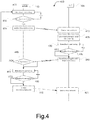
- FIG. 4 illustrates a process 400 that shows the actions taken by the devices of the communications network of FIG. 1 , in accordance with various example embodiments.
- the process 400 may be used to provide feedback for a data transmission that is communicated over an unlicensed shared medium.
- the operations of process 400 will be described as being performed by the UE 105 and the eNB 110, which are described with respect to FIGS. 1-3 .
- other similar devices may operate the process 400 as described below. While particular examples and orders of operations are illustrated in FIG. 4 , in various embodiments, these operations may be re-ordered, broken into additional operations, combined, and/or omitted altogether.
- the eNB 110 may perform a medium-sensing operation.
- a channel sensing mechanism may be employed to determine an empty and/or unoccupied channel before transmitting the feedback in the unlicensed band. This may be referred to as a "listen-before-talk” (LBT) contention mechanism.
- LBT listen-before-talk
- the term “medium sensing” may also be referred to as “carrier sensing”, “channel sensing”, LBT, and the like.
- the UE 110 In order to ensure reliable reception of the feedback data (for example, HARQ-ACK, HARQ-NACK, etc.), as well as reducing collisions with transmission from other RATs and/or Wi-Fi devices operating in the 5 GHz band, the UE 110 first senses the medium. It should be noted that FIG. 4 illustrates one possible embodiment of this mechanism, and according to various embodiments, the eNB 110 may perform a medium-sensing operation over multiple unlicensed channels to detect or otherwise determine an empty channel in an unlicensed shared medium.
- the feedback data for example, HARQ-ACK, HARQ-NACK, etc.
- the eNB 110 determines whether the medium is empty. If the eNB 110 determines that the medium is not empty (for example, that a channel of the unlicensed spectrum is occupied), then the eNB 110 proceeds back to operation 405 to perform the medium-sensing operation for one or more other channels in the unlicensed spectrum that may be unoccupied. If the eNB 110 determines that the medium is empty or unoccupied, then the eNB 110 proceeds to operation 415 to transmit a data transmission to the UE 105 over the detected channel in the unlicensed spectrum.
- the UE 105 receives the data transmission from the eNB 110.
- the UE 105 performs demodulation and/or decoding operations. Many methods for demodulating and/or decoding data transmissions are generally well-known, and thus, a further detailed description of the methods for demodulating and/or decoding data transmissions is omitted.
- the UE 105 performs a medium-sensing operation.
- the medium-sensing operation performed by the UE 105 may be the same or similar to the medium-sensing operation described previously with regard to operation 405. If the UE 105 determines that the medium is not empty (for example, that a channel of the medium is occupied), then the UE 105 proceeds back to operation 430 to perform the medium-sensing operation for one or more other channels in the unlicensed spectrum that may be unoccupied.
- the UE 105 determines that the medium is empty or unoccupied, then the UE 105 proceeds to operations 340 to transmit a feedback (for example, HARQ-ACK, HARQ-NACK, etc.) associated with the data transmission to the eNB 110.
- a feedback for example, HARQ-ACK, HARQ-NACK, etc.
- the UE 105 once the UE 105 detects or otherwise determines an empty channel on the unlicensed spectrum, it will transmit feedback information over it.
- the empty channel may be the same channel in which the UE 105 received the data transmission from the eNB 110, or the UE 105 may use an empty channel that is different than the channel in which the UE 105 received the data transmission from the eNB 110.
- the UE 105 may use the PUCCH or the PUSCH to transmit HARQ-ACK/NACK feedback.
- a PUCCH transmission is usually only allowed on a primary cell (PCell) and a secondary cell (SCell) for a dual connectivity scenario.
- M number of PUCCH channels that operate on different carriers in the unlicensed band may be semi-statically configured by a higher layer signaling for each LTE-U capable UEs (for example, UEs 105).
- the UE 105 selects one available PUCCH channel from the M number of PUCCH channels that may be detected according to the medium/carrier sensing operation.
- the eNB 110 may dynamically configure the number of M values that each of the UEs 105 may use for selecting the PUCCH channels.
- the UE 105 may also detect or otherwise determine an empty channel for transmitting feedback on an unlicensed band that is different than the unlicensed band that was used by the eNB 110 to transmit the data transmission.
- the eNB 110 receives the feedback message from the UE 105 and determines whether the feedback is one of a HARQ-ACK message or a HARQ-NACK message. If at operation 445, the eNB 110 determines that the feedback is a HARQ-ACK message, then eNB 110 proceeds back to operation 405 to perform a medium-sensing operation for transmission of a new data transmission. If at operation 445, the eNB 110 determines that the feedback is a HARQ-NACK message or a discontinuous transmission (DTX) message, then eNB 110 proceeds to operation 450 to perform a medium-sensing operation.
- DTX discontinuous transmission
- the medium-sensing operation may be the same or similar as the medium-sensing operation performed at operations 405 and 430.
- the eNB 110 determines whether the medium is empty. If the eNB 110 determines that the medium is not empty (for example, that a channel of the medium is occupied), then the eNB 110 proceeds back to operation 450 to perform the medium-sensing operation for one or more other channels in the unlicensed spectrum that may be unoccupied. If the eNB 110 determines that the medium is empty or unoccupied, then the eNB 110 proceeds to operation 460 to retransmit the data transmission to the UE 105 over the detected channel in the unlicensed spectrum. At operation 465 the UE 105 receives the data retransmission from the eNB 110.
- FIG. 5 illustrates a process 500 for flexible feedback timing mechanism, in accordance with various example embodiments.
- the operations of process 500 will be described as being performed by the UE 105, which is described with respect to FIGS. 1-3 .
- other similar devices may operate the process 500 as described below. While particular examples and orders of operations are illustrated in FIG. 5 , in various embodiments, these operations may be re-ordered, broken into additional operations, combined, and/or omitted altogether.
- process 500 provides a flexible HARQ-ACK feedback timing mechanism to ensure the aforementioned latency requirements.
- the UE 105 may define a fixed timing relation between a data transmission and a feedback transmission.
- a timing relation between the reception of a data transmission and a transmit time for a feedback transmission is made as short as possible while also considering tradeoffs between latency and receiver processing complexity.
- a fixed timing relation between the reception of data transmissions in a downlink channel and transmission of corresponding feedback messages in an uplink channel is delineated by the current LTE standards.
- a frequency-division duplexing (also referred to as a "FDD deployment")
- FDD frequency-division duplexing
- a data transmission is transmitted on a downlink (for example, PDSCH) subframe n by a base station (for example, eNB 110)
- a user equipment for example, UE 105
- HARQ-ACK/NACK transmission on corresponding n+4 uplink (for example, PUCCH, PUSCH, etc.) subframe.
- TDD time-division duplexing
- a data transmission is transmitted on a downlink (for example, PDSCH) subframe n by a base station (for example, eNB 110)
- a user equipment for example, UE 105
- HARQ-ACK/NACK transmission on corresponding uplink (for example, PUCCH, PUSCH, etc.) subframe n+k, where the value of k is predefined value, for example, as defined in in 3GPP's technical specification (TS) 36.213.
- TS technical specification
- the time period between the reception of a data transmission and the transmission of a feedback message may be referred to as a "transmission window.” Since the timing relation between the reception of a data transmission over the PDSCH and the transmit time for the corresponding HARQ-ACK/NACK transmission is fixed (for example, a "fixed transmission window") for transmission in the licensed spectrum, the base station may already know of the corresponding uplink channel on which the HARQ-ACK/NACK is intended.
- each subframe is 1 millisecond (ms) and/or 2 resource blocks (RBs) long
- the fixed transmission window for TDD deployments is 4 ms and/or 8 RBs long
- the fixed transmission window for FDD deployments is k ms and/or (2*k) RBs long.
- the UE 105 determines the fixed timing relation between the data transmission and the feedback transmission, such as n to n+4 for FDD deployments and n to n+k for TDD deployments, in order to determine whether it is feasible to transmit the feedback using the fixed transmission window.
- the UE 105 may determine whether the predefined feedback resource is available for transmitting the feedback transmission.
- the predefined feedback resource may be a subframe or RB for which a feedback is intended to be transmitted on (for example, the n+k subframe for TDD deployments or the n+4 subframe for FDD deployments).
- the UE 105 may perform various signaling operations with the eNB 110 in order to determine if another transmission is scheduled to be transmitted using the predefined resource.
- the UE 105 may perform a medium-sensing operation in order to determine if another transmission is scheduled to be transmitted using the predefined resource in order to determine whether the predetermined feedback resource is available or not. If at operation 510 the UE 105 determines that the predefined feedback resource is available or unoccupied, then the UE 105 may proceed to operation 535 to transmit the feedback transmission using the predefined feedback resource. If at operation 510 the UE determines that the predefined feedback resource is not available or is otherwise occupied, then the UE 105 may proceed to operation 515 to perform a medium-sensing operation to detect an unoccupied feedback resource for transmitting the feedback transmission.
- the UE 105 may perform the medium-sensing operation.
- the medium-sensing operation may be the same or similar as the medium-sensing operation as previously discussed herein. It should be noted that, when utilizing the unlicensed spectrum, the timing relationship between data transmissions transmitted over the PDSCH and the corresponding HARQ-ACK/NACK feedback may not be guaranteed due to the potential of collisions and/or interruptions caused by other data packets. Therefore, when utilizing the unlicensed spectrum, a base station may not receive the HARQ-ACK/NACK feedback for which a PDSCH data transmission is intended. Accordingly, in various example embodiments, an expanding transmission window (also referred to as a "flexible transmission window”) is introduced.
- the corresponding feedback can be transmitted on an uplink subframe n + 4 ⁇ 1 for FDD deployments, and on subframe n + k ⁇ 1 for TDD deployments.
- the value of k is pre-defined in, for example, TS 36.213.
- the value of 1 is an integer number (for example, 0, 1,2,..., etc.).
- the eNB 110 when a HARQ-ACK/NACK feedback transmission is transmitted on an unlicensed band, in various embodiments the eNB 110 will look for or otherwise detect the feedback transmission within a range of subframes, such as from n to n + 4 ⁇ 1 for FDD deployments and from n to n + k ⁇ 1 for TDD deployments, instead of just looking for one subframe (for example, the predefined feedback resource).
- the range or value of 1 could be predefined at the eNB 110, whereby 1 is selected by a wireless network operator according to one or more design choices and/or based on one or more empirical studies.
- the value of 1 may be chosen or otherwise determined by the UE 105 (for example, as discussed with regard to operation 525) and communicated to the eNB 110 using higher layer signaling than the transmission of the feedback.
- the UE 105 may determine whether another feedback resource is available for transmitting the feedback transmission. If at operation 520 the UE determines that the other feedback resource is not available, then the UE 105 proceeds back to operation 515 to perform the medium-sensing operation to detect another unoccupied feedback resource in the unlicensed spectrum. If at operation 510 the UE determines that other feedback resources are available, then the UE 105 proceeds to operation 525 to select an unoccupied one of the available feedback resources.
- the UE 105 may select an unoccupied feedback resource for transmitting the feedback transmission. Because the UE 105 may have to perform multiple medium-sensing operations at operation 520, in various embodiments the UE 105 may start a HARQ-ACK/NACK feedback timer once the HARQ-ACK/NACK feedback is not transmitted according to the fixed timing relation or fixed transmission window. The HARQ-ACK/NACK feedback timer may expire once the UE 105 selects a feedback resource for transmitting the feedback. Once the HARQ-ACK/NACK feedback timer expires, the UE 105 may discard the suspending HARQ-ACK/NACK information.
- the eNB 110 may perform HARQ-ACK/NACK/DTX detection within a range of uplink subframes, where the range of uplink subframes is based on the HARQ-ACK/NACK feedback timer length at the UE 105.
- the HARQ-ACK/NACK feedback timer length may be communicated to the eNB 110 using higher layer signaling than the transmission of the feedback.
- the eNB 110 may then reconfigure semi-static resources (for example, carrier index, band number, and/or different power control parameters) for the HARQ-ACK/NACK feedback for the UE 105.
- the UE 105 may transmit the feedback on the selected resource.
- FIG. 6 illustrates a feedback message 600 including multiplexed HARQ process numbers (HPNs) along with ACK/NACK bits, in accordance with various example embodiments.
- FIG. 7 illustrates an implicit representation of HPNs by fixing the HARQ ACK/NACK position for different HPNs, in accordance with various example embodiments.
- the flexible timing relation as discussed with regard to FIG. 5 may cause ambiguity and/or potential PUCCH resource collision between different HARQ processes at the eNB 110.
- various example embodiments provide that the HARQ-ACK/NACK bits associated with one or more HARQ Process Numbers (HPNs) may be multiplexed with the HPNs, such that the ACK/NACK bits and the HPNs may be combined into a single message and transmitted on an available uplink subframe.
- HPNs HARQ Process Numbers
- the HPNs associated with one or more ACK/NACK bits may indicate a HARQ process to be used for decoding the ACK/NACK bits and/or an order in which to process the ACK/NACK bits.
- uplink and downlink HARQ-ACK/NACK feedback messages should only contain ACK/NACK bits.
- the fixed timing relationship between the downlink (for example, PDSCH) and HARQ-ACK/NACK feedback is not guaranteed due to potential collisions or potential interruptions by other packets in the unlicensed band, there may be confusion on HARQ-ACK/NACK feedback for which a data transmission is intended.
- FIG. 6 shows one example embodiment of a multiplexed feedback message that includes the HPNs along with ACK/NACK bits.
- a 3-bit process number is used for FDD deployments.
- a 4-bit HPN can be used.
- the HPNs may be added after the ACK/NACK bits.
- the HPNs can precede the ACK/NACK bits. From these HPN bits, the eNB 110 may determine the HARQ process number.
- the modified bit patterns including HPNs may use the PUCCH format 3 or use another format. It should be noted that multiplexing the HPNs along with ACK/NACK bits may allow for the transmission of a flexible number of ACK/NACK bits in each feedback message, where the number of bits transmitted in a particular feedback transmission (for example, a PUCCH transmission or a PUSCH transmission) can be determined implicitly from the number of missed feedback transmission opportunities (for example, a number of times that the UE 105 was unable to transmit feedback due to an occupied channel and/or subframe in the unlicensed spectrum).
- a particular feedback transmission for example, a PUCCH transmission or a PUSCH transmission
- missed feedback transmission opportunities for example, a number of times that the UE 105 was unable to transmit feedback due to an occupied channel and/or subframe in the unlicensed spectrum.
- the HPNs of a transmitted ACK/NACK can be calculated or otherwise determined at the eNB 110 by fixing the position of each HBN bit within the feedback transmission message.
- the UE 105 may not have to transmit the HBNs to the eNB 110.
- FIG. 8 illustrates a timing diagram 800 for transmission of delayed feedback at different subframe locations, in accordance with various example embodiments.
- timing diagram 800 illustrates the transmission of delayed HARQ-ACK/NACK feedback at a different positions on a new subframe. For example, if the PUCCH transmission is used for HARQ-ACK feedback (as is illustrated be FIG.
- the PUCCH resources transmission may be determined by either explicit signaling by the UE 105 or implicitly by the eNB 110 (for example, as a function of a first control channel element (CCE) index in case of PUCCH format 1a or format 1b).
- CCE first control channel element
- Uplink (for example, PUCCH) resources that are mapped to a first HARQ-ACK/NACK feedback intended for a first downlink (for example, PDSCH) transmission at a predefined first subframe may be occupied by a second HARQ-ACK/NACK feedback intended for a second PDSCH transmission at the predefined first subframe. Since the mapped PUCCH resources may be not available for the first HARQ-ACK/NACK feedback transmission, a transmission of the first HARQ-ACK/NACK feedback transmission may be delayed. According to various embodiments, a new PUCCH region may be defined for the delayed HARQ-ACK/NACK feedback.
- the timing diagram 800 shows subframe k, subframe k+1, and subframe k+2, each of which is 1 milliseconds (ms) long.
- Each subframe k, k+1, and k+2 includes 2 slots, where each slot is 0.5 ms.
- Each slot includes 1 resource block (RB) and each subframe includes 2 RBs.
- the RBs in the licensed spectrum may be labeled as RB0, RBI, RB2,...RBk+r+n-1, and the RBs in the unlicensed spectrum may be labeled as N RB UL ⁇ k-1 ... N RB UL ⁇ 1 .
- the subframes of timing diagram 800 may be included in a type 1 frame for FDD deployments or a type 2 frame for TDD deployments.
- the unlicensed medium is busy during subframe k and subframe k+1. Therefore, uplink transmission of feedback 805 may not be possible in subframe k and uplink transmission of feedback 810 may not be possible in subframe k+1.
- the unlicensed medium is empty and the UE 105 has an opportunity to perform uplink transmission for feedback 805 and feedback 810. Therefore, the feedback transmissions for feedback 805 and feedback 810 intended to be transmitted during subframe k and subframe k+1, respectively, may both be transmitted in subframe k+2.
- subframe k+2 has its own associated feedback 815 scheduled for transmission in the reserved PUCCH region as shown in FIG. 8 .
- a new PUCCH resource offset may be introduced.
- the PUCCH region from subframe k and k+1 can be shifted to start from a different RB position or a PUCCH resource index in subframe k+2 as shown in FIG. 8 .
- the resource position will be shifted by a resource offset.
- the offset values 1 and r and the number of additional subframes that may be allocated to feedback transmissions can be signaled using higher layer signaling than the signaling used for transmitting the feedback.
- FIG. 9 illustrates various state tables of a receiver state showing various states of the receiver based on received feedback according to a modified feedback transmission mechanism, in accordance with various example embodiments.
- the modified feedback transmission mechanism shown by FIG. 9 may be referred to as a "default NACK mode" for feedback transmission.
- feedback messages may be transmitted in response to both a proper decoding and/or demodulation of a data transmission (for example, ACK) and an improper decoding and/or demodulation of a data transmission (for example, NACK).
- ACK a data transmission
- NACK an improper decoding and/or demodulation of a data transmission
- a default NACK state can be used to reduce a number of feedback transmissions made by the UE 105. In such embodiments, if a received signal or data transmission is not decoded correctly (for example, NACK state), then the UE 105 will refrain from transmitting any feedback or other like acknowledgement signal.
- the absence of an acknowledgement signal at the UE 105 may be interpreted to be in a NACK state, and the eNB 110 may retransmit the data transmission.
- the eNB 110 may assume that the UE 105 is in a NACK state and the eNB 110 may retransmit the data transmission. If on the other hand, the received signal is decoded correctly, UE 105 may transmit HARQ-ACK signal to the eNB 110.
- each of tables 1-3 show as examples, a receiver (for example, UE 105) state for an FDD single carrier when using the current LTE specifications for feedback mechanisms in comparison with receiver states for FDD single carrier feedback when using the default NACK state mechanism of various example embodiments.
- the term "ACK” in each of tables 1-3 signifies a state of the receiver in response to a proper decoding and/or demodulation operation of at least one portion of a data transmission
- the term "NACK" in each of tables 1-3 signifies a state of the receiver in response to an improper decoding and/or demodulation operation of at least one portion of a data transmission.
- a value of "1" in a feedback message sent by the receiver may indicate that the receiver is in an ACK state for at least one portion of a data transmission
- a value of "0" in a feedback message sent by the receiver may indicate that the receiver is in a NACK state for at least one portion of a data transmission
- a value of "X" may indicate that no feedback data is sent by the receiver.
- Table 1 shows the receiver states for a 1 bit feedback transmission protocol in an FDD deployment, according to an example embodiment.
- the receiver may send a feedback message including a bit value of "1" indicating that the receiver is in the ACK state (for example, that the receiver properly decoded and/or demodulated a data transmission), and the receiver may send a feedback message including a bit value of "0" indicating that the receiver is in the NACK state (for example, that the receiver did not properly decoded and/or demodulated a data transmission).
- the receiver may send a feedback message including a bit value of "1" indicating that the receiver is in the ACK state (for example, that the receiver properly decoded and/or demodulated a data transmission), and the receiver does not send a feedback message indicating that the receiver is in the NACK state (for example, that the transmitter assumes that the receiver is in the NACK state).
- Table 1 also indicates that, by not sending the NACK feedback, 1 bit feedback transmission protocol according to this example embodiment should provide an overhead reduction of approximately 50%.
- Table 2 shows the receiver states for a 2 bit feedback transmission protocol, according to a first example embodiment.
- the example embodiment shown by table 2 may be used for networks employing HARQ with soft combining, wherein incorrectly received coded data blocks may be stored in a buffer at the receiver rather than being discarded by the receiver.
- soft combining when a retransmitted block is received at the receiver, the retransmitted block may be combined with the stored block.
- the receiver may send a feedback message including a bit value of "1,1" indicating that the receiver is in the ACK state for two portions of a received data transmission (for example, that the receiver properly decoded and/or demodulated two portions of a data transmission); the receiver may send a feedback message including a bit value of "1,0" indicating that the receiver is in the ACK state for a first portion of a received data transmission and a NACK state for a second portion of the data transmission (for example, that the receiver did not properly decode and/or demodulate the second portion of the data transmission and would like the transmitter to retransmit the second portion of the data transmission); the receiver may send a feedback message including a bit value of "0,1" indicating that the receiver is in the NACK state for a first portion of a received data transmission and in the ACK state for a second portion of the data transmission (for example, that the receiver did not properly decode and/or demodulate
- the receiver may send a feedback message including a bit value of "1,1" indicating that the receiver is in the ACK state for two portions of a received data transmission (for example, that the receiver properly decode and/or demodulate two portions of a data transmission); the receiver may send a feedback message including a bit value of "1,0" indicating that the receiver is in the ACK state for a first portion of a received data transmission and a NACK state for a second portion of the data transmission (for example, that the receiver did not properly decode and/or demodulate the second portion of the data transmission and would like the transmitter to retransmit the second portion of the data transmission); the receiver may send a feedback message including a bit value of "0,1" indicating that the receiver is in the NACK state for a first portion of a received data transmission and in the ACK state for a second portion of the data transmission (for example, that the receiver did not properly decode and/or demodulate the first portion of the data transmission).
- Table 3 shows the receiver states for a 2-bit feedback transmission protocol, according to a second example embodiment.
- Table 3 shows the same 2-bit feedback transmissions under the current LTE specifications as described previously with regard to table 2.
- the receiver may send a feedback message including a bit value of "1" indicating that the receiver is in the ACK state for a received data transmission in a same or similar manner as discussed previously with regard to the example embodiment shown by table 1.
- the receiver according to the second example embodiment does not send any feedback message when any portion of a data transmission is improperly decoded and/or demodulated, which is indicated by the value "X" in each of the third through fourth rows of the "Receiver Feedback (example embodiment)" column of table 3.
- the transmitter assumes that the receiver is in the NACK state whenever any portion of a data transmission is not properly decoded and/or demodulated).
- Table 3 also indicates that, by not sending the NACK feedback when any portion of a data transmission is improperly decoded and/or demodulated, the 2-bit feedback transmission protocol according to the second example embodiment should provide an overhead reduction of approximately 75%.
- the second example embodiment for the 2-bit feedback transmission protocol may result in more data retransmission by the transmitter.
- HARQ-ACK feedback may only be transmitted when a UE correctly receives control signaling related to a downlink transmission over a shared channel (for example, DLSCH) intended for the UE on one of the downlink control channels (for example, one of the PDCCHs). If no valid DLSCH related control signaling is detected by the UE, no feedback signal is transmitted to the eNB, which is known as DTX. Therefore, in typical LTE systems, at the eNB, a three state detection of an ACK state, a NACK state, and a DTX state is performed.
- the eNB 110 may not be able to determine whether the UE 105 is in the NACK state or the DTX state.
- a retransmission may occur when the UE 105 is in either the NACK state or the DTX state in a similar fashion as the PUCCH format 3 transmissions.
- FIG. 10 illustrates a process 1000 that shows the actions taken by the devices of the communications network of FIG. 1 , in accordance with various example embodiments.
- the eNB 110 may end up retransmitting the data transmission even though the data retransmission may not be necessary.
- various example embodiments provide for the combination of the previously discussed flexible transmission window example embodiments with the default NACK mode example embodiments.
- the combination of these example embodiments may be based on a wireless network operators network design choices.
- the UE 105 may transmit the feedback data within a range of subframes, and the eNB 110 may look for the feedback information within the range of subframes. If ACK data is not available within the range of subframes, the eNB 110 may consider the UE 105 to be in a NACK state and retransmit a data transmission.
- the eNB 110 transmits a first data transmission to the UE 105.
- the UE 105 successfully decodes and/or demodulates the first data transmission.
- the UE 105 attempts to transmit HARQ-ACK feedback that is intended for the first data transmission.
- the UE 105 may perform a medium-sensing operation in order to determine whether one of the subframes of the range of subframes is busy or otherwise occupied. In such embodiments, the UE 105 may continue to perform the medium-sensing operations until the UE 105 detects an available sub frame. Each time the UE 105 performs a medium-sensing operation may be considered an attempt to transmit feedback data. As shown, the UE 105 attempts to transmit the ACK feedback twice (for example, ACK attempt 1 and ACK attempt 2 as shown) and determines that the medium is busy at operation 1020.
- the first attempt may include detecting whether the predefined subframe for the fixed transmission window is available or otherwise unoccupied.
- the UE 105 may scan for available or unoccupied subframes in the unlicensed spectrum according to the example embodiments previously discussed. Furthermore, in some embodiments, the UE may scan for available or unoccupied subframes in an unlicensed spectrum that is different than the unlicensed spectrum used for transmitting the data transmission. Referring back to operation 1015, on the third attempt or third medium-sensing operation (for example, ACK attempt 3 as shown), the UE 105 detects an available subframe of the range of subframes and transmits the ACK feedback on the available subframe.
- the third attempt or third medium-sensing operation for example, ACK attempt 3 as shown
- the eNB 110 scans the range of subframes for the ACK transmission that is intended for the first data transmission. Because the UE 105 was able to transmit the ACK feedback on a subframe within the range of subframes, and/or the eNB 110 obtained the ACK feedback within the desired time period for obtaining feedback, at operation 1030 the eNB 110 transmits a second data transmission to the UE 105.
- the UE 105 does not properly decode and/or demodulate the second data transmission, and thus, the UE 105 does not transmit NACK feedback or any other like feedback message or signal for the second data transmission.
- the eNB 110 scans for ACK feedback for the second data transmission. Because the UE 105 was unable to transmit the ACK feedback on any of the subframes within the range of subframes, and/or the eNB 110 did not obtain feedback within the desired time period for obtaining feedback, at operation 1045 the eNB 110 retransmits the second data transmission to the UE 105.
- the described example embodiments pertain to transmitting feedback in an uplink channel in response to receiving downlink data transmissions in an unlicensed shared medium.
- the example embodiments described herein above may be extended to to uplink data transmissions and corresponding feedback transmission transmitted in over a downlink channel in an unlicensed shared medium.
Description
- Implementations of the claimed invention generally relate to the field of wireless communications, and in particular, utilizing unlicensed spectrum in Long Term Evolution (LTE) wireless communications networks.
- As demand for wireless data in cellular networks increases, user expectations of high data rates along with seamless mobility also increases. In order to fulfill the increasing user expectations of high data rates and seamless mobility, more wireless network spectrum may need to be made available for wireless subscribers. Typical Long Term Evolution (LTE) wireless networks are designed to use a dedicated licensed spectrum. The spectrum in which a wireless network operator deploys a LTE network is solely used by that operator to serve that operator's wireless network subscribers. To meet the growing demand for wireless network spectrum, the 3rd Generation Partnership Project (3GPP) has proposed using radio-frequency carriers in the unlicensed spectrum, which is often referred to as "Long Term Evolution (LTE) in Unlicensed" ("LTE-U") (also referred to as Licensed-Assisted Access (LAA)). Generally, the unlicensed spectrum includes frequencies in the 5GHz band.
- The basic premise of LTE-U is to extend the LTE protocols into the unlicensed spectrum in order to supplement data traffic in the licensed spectrum. Because wireless network operators deploy their LTE systems in their corresponding licensed spectrum, data transmission and related acknowledgement feedback do not typically require any contention mechanisms. However, since the unlicensed spectrum can be shared by more than one wireless network operator, as well as other radio access technologies (for example, Wi-Fi), sharing and contention mechanisms may be required to deploy LTE in the unlicensed spectrum.
- When LTE-U is used as a supplemental carrier, the aforementioned contention mechanisms can be employed to transmit downlink and/or uplink data using the unlicensed spectrum. Even though data is transmitted using the unlicensed spectrum, it is more likely that the transmission of more delay and quality of service (QoS) sensitive service (for example, hybrid automatic repeat request (HARQ)-acknowledgement (ACK) feedback), will likely be carried out using the licensed spectrum because the licensed spectrum may be considered more reliable than the unlicensed spectrum. However, as the use of the unlicensed spectrum increases, the transmission of HARQ-ACK feedback over licensed channel will likely induce significant overheads. Therefore, the use of unlicensed band for HARQ-ACK feedback transmission may be advantageous.
- Moreover, several scenarios can be envisioned for the future 5G technology, where LTE will be deployed as a Stand-Alone (SA) carrier in the unlicensed band. Therefore, new mechanisms may be required to transmit HARQ-ACK information in the unlicensed band.
-
US 2014/0112289 A1 relates to a method for transmitting a signal to an unlicensed band of a base station in a wireless communication system. The method comprises the steps of: transmitting at least one of a preamble and a reservation signal, if it is determined through carrier sensing that the unlicensed band is available; and transmitting a PDSCH on the unlicensed band immediately after the transmission of at least one of the preamble and the reservation signal. The preamble enables a terminal to acquire reception synchronization for at least one of the reservation signal and the PDSCH. -
US 2013/0225184 A1 discloses a system for operating a communications controller for a group of user equipments engaged in a direct mobile communication (DMC) link in a wireless communications system. The communications controller is configured to allocate a set of subframes in one periodic group of subframes to the group of UEs for the DMC link, signal the set of allocated subframes to the group of UEs, and transmit parameters related to a group of HARQ processes of the DMC link. In an embodiment, the communication controller uses HARQ processes for cellular UE transmission that are determined independently from HARQ processes of the group of HARQ processes for the DMC link, and the parameters are configured to enable the group of UEs to manage the group of HARQ processes for the DMC link. - 3GPP Tdoc. R1-144042, "Candidate solutions for LAA operation", 3GPP TSG RAN WG1 Meeting #78bis, October 2014, relates to discuss potential candidate solutions for
licensed-assisted access (LAA) operation in terms of radio access scheme for coexistence with other systems/operators and the relevant improvement for reliable operation/resource utilization in unlicensed band. - The invention is defined by the subject matter of the independent claims. Advantageous embodiments are subject to the dependent claims.
- Embodiments will be readily understood by the following detailed description in conjunction with the accompanying drawings. To facilitate this description, like reference numerals designate like structural elements. Embodiments are illustrated by way of example and not by way of limitation in the figures of the accompanying drawings.
-
FIG. 1 illustrates a communications network in accordance with various example embodiments; -
FIG. 2 illustrates the components of a user equipment (UE) and an evolved Node B (eNB) in accordance with various example embodiments; -
FIG. 3 illustrates the components of a computing system that may implement the example embodiments disclosed herein, in accordance with various example embodiments; -
FIG. 4 illustrates actions taken by the devices of the communications network ofFIG. 1 , in accordance with various example embodiments; -
FIG. 5 illustrates aprocess 500 for flexible feedback timing mechanism, in accordance with various example embodiments; -
FIG. 6 illustrates a feedback message including multiplexed HARQ process numbers (HPN) along with ACK/NACK bits, in accordance with various example embodiments; -
FIG. 7 illustrates an implicit representation of HPNs by fixing the HARQ ACK/NACK position for different HPNs, in accordance with various example embodiments; -
FIG. 8 illustrates a timing diagram for transmission of delayed feedback at different subframe location, in accordance with various example embodiments; -
FIG. 9 illustrates various state tables of a receiver state showing various states of the receiver based on received feedback according to a modified feedback transmission mechanism, in accordance with various example embodiments; and -
FIG. 10 illustrates aprocess 1000 that shows the actions taken by the devices of the communications network ofFIG. 1 , in accordance with various example embodiments. - The invention is set out in the appended claims. The references to embodiments in the description falling outside the scope of the appended claims are to be understood as mere examples which are useful for understanding the invention.
- The following detailed description refers to the accompanying drawings. The same reference numbers may be used in different drawings to identify the same or similar elements. In the following description, for purposes of explanation and not limitation, specific details are set forth such as particular structures, architectures, interfaces, techniques, etc. in order to provide a thorough understanding of the various aspects of the claimed invention. However, it will be apparent to those skilled in the art having the benefit of the present disclosure that the various aspects of the invention claimed may be practiced in other examples that depart from these specific details. In certain instances, descriptions of well-known devices, circuits, and methods are omitted so as not to obscure the description of the present invention with unnecessary detail.
- Various aspects of the illustrative embodiments will be described using terms commonly employed by those skilled in the art to convey the substance of their work to others skilled in the art. However, it will be apparent to those skilled in the art that alternate embodiments may be practiced with only some of the described aspects. For purposes of explanation, specific numbers, materials, and configurations are set forth in order to provide a thorough understanding of the illustrative embodiments. However, it will be apparent to one skilled in the art that alternate embodiments may be practiced without the specific details. In other instances, well-known features are omitted or simplified in order not to obscure the illustrative embodiments.
- Further, various operations will be described as multiple discrete operations, in turn, in a manner that is most helpful in understanding the illustrative embodiments; however, the order of description should not be construed as to imply that these operations are necessarily order dependent. In particular, these operations need not be performed in the order of presentation.
- The phrase "in various embodiments", "in some embodiments", and the like are used repeatedly. The phrase generally does not refer to the same embodiments; however, it may. The terms "comprising," "having," and "including" are synonymous, unless the context dictates otherwise.
- The phrase "A and/or B" means (A), (B), or (A and B). The phrases "A/B" and "A or B" mean (A), (B), or (A and B), similar to the phrase "A and/or B". For the purposes of the present disclosure, the phrase "at least one of A and B" means (A), (B), or (A and B).
- The description may use the phrases "in an embodiment", or "in embodiments", which may each refer to one or more of the same or different embodiments. Furthermore, the terms "comprising," "including," "having," and the like, as used with respect to embodiments of the present disclosure, are synonymous.
- It should be noted that example embodiments may be described as a process depicted as a flowchart, a flow diagram, a data flow diagram, a structure diagram, or a block diagram. Although a flowchart may describe the operations as a sequential process, many of the operations may be performed in parallel, concurrently, or simultaneously. In addition, the order of the operations may be re-arranged. A process may be terminated when its operations are completed, but may also have additional steps not included in the figure(s). A process may correspond to a method, a function, a procedure, a subroutine, a subprogram, and the like. When a process corresponds to a function, its termination may correspond to a return of the function to the calling function and/or the main function.
- As used herein, the term "circuitry" refers to, is part of, or includes hardware components such as an Application Specific Integrated Circuit (ASIC), an electronic circuit, a logic circuit, a processor (shared, dedicated, or group) and/or memory (shared, dedicated, or group) that are configured to provide the described functionality. In some embodiments, the circuitry may execute one or more software or firmware programs to provide at least some of the described functionality. Example embodiments may be described in the general context of computer-executable instructions, such as program code, software modules, and/or functional processes, being executed by one or more of the aforementioned circuitry. The program code, software modules, and/or functional processes may include routines, programs, objects, components, data structures, etc. that perform particular tasks or implement particular data types. The program code, software modules, and/or functional processes discussed herein may be implemented using existing hardware in existing communication networks. For example, program code, software modules, and/or functional processes discussed herein may be implemented using existing hardware at existing network elements or control nodes.
- As used herein, the term "user equipment" may be considered synonymous to, and may hereafter be occasionally referred to, as a client, mobile, mobile device, mobile terminal, user terminal, mobile unit, mobile station, mobile user, UE, subscriber, user, remote station, access agent, user agent, receiver, etc., and may describe a remote user of network resources in a communications network. Furthermore, the term "user equipment" may include any type of wireless/wired device such as consumer electronics devices, cellular phones, smart phones, tablet personal computers, wearable computing devices, personal digital assistants (PDAs), desktop computers, and laptop computers, for example.
- As used herein, the term "network element", may be considered synonymous to and/or referred to as a networked computer, networking hardware, network equipment, router, switch, hub, bridge, radio network controller, radio access network device, gateway, and/or any other like device. The term "network element" may describe a physical computing device of a wired or wireless communication network and configured to host a virtual machine. Furthermore, the term "network element" may describe equipment that provides radio baseband functions for data and/or voice connectivity between a network and one or more users. The term "network element", may be considered synonymous to and/or referred to as a "base station". As used herein, the term "base station", may be considered synonymous to and/or referred to as a Node B, an enhanced or evolved Node B (eNB), base transceiver station (BTS), access point (AP), etc. and may describe equipment that provides the radio baseband functions for data and/or voice connectivity between a network and one or more users.
- It should also be noted that the term "channel" as used herein may refer to any transmission medium, either tangible or intangible, which is used to communicate data or a data stream. Additionally, the term "channel" may be synonymous with and/or equivalent to "communications channel", "data communications channel", "transmission channel", "data transmission channel", "access channel", "data access channel", "link", "data link", "carrier", "radiofrequency carrier", and/or any other like term denoting a pathway or medium through which data is communicated.
- Example embodiments are generally directed towards the design of Long Term Evolution - Unlicensed (LTE-U) and Licensed-Assisted Access (LAA) as a Stand-Alone (SA) carrier in the unlicensed spectrum, and more specifically, example embodiments are directed towards new hybrid automatic repeat request (HARQ) feedback mechanisms that may be used for data transmissions in an unlicensed shared medium.
-
FIG. 1 illustrates an example of acommunications network 100, according to an example embodiment.Communications network 100 includes user equipments (UEs) 105, e Node B (eNB) 110, andcore network 115. - Referring to
FIG. 1 , each of the UEs 105 (collectively referred to as "UE 105") may be physical hardware devices that are capable of running one or more applications and capable of connecting with a network element (for example, BSs 110) via a wireless interface.UE 105 may include a transmitter/receiver (or alternatively, a transceiver), memory, one or more processors, and/or other like components.UE 105 may be configured to send/receive data to/from at least one of the BSs 110 (collectively referred to as "eNB 110").UE 105 may be designed to sequentially and automatically carry out a sequence of arithmetic or logical operations; equipped to record/store digital data on a machine readable medium; and transmit and receive digital data viabase station 110.UE 105 may include wireless phones or smartphones, laptop personal computers (PCs), tablet PCs, wearable computing devices, and/or any other physical or logical device capable of recording, storing, and/or transferring digital data viabase station 110 and/or any other like network element. The wireless transmitter/receiver (or alternatively, a transceiver) included in theUE 105 is configured to operate in accordance with one or more wireless communications protocols and/or one or more cellular phone communications protocols.UE 105 may be configured to operate in accordance with the 3rd Generation Partnership Project (3GPP) Long Term Evolution-Advanced (LTE-A) standards and/or any other wireless communication protocols, including RF-based, optical (visible/invisible), and so forth. - In various embodiments, the
UE 105 may be configured to communicate data (for example, transmit and receive) data over a licensed shared medium (also referred to as the "licensed spectrum" and/or the "licensed band") and an unlicensed shared medium (also referred to as the "unlicensed spectrum" and/or the "unlicensed band"). The licensed spectrum may include channels that operate in the frequency range of approximately 400 MHz to approximately 3.8 GHz, whereas the unlicensed spectrum may include the 5 GHz band. Additionally, theUE 105 may be configured to perform one or more known medium-sensing operations and/or carrier-sensing operations in order to determine whether one or more channels in the unlicensed spectrum is unavailable or otherwise occupied. - Referring back to
FIG. 1 ,eNB 110 is a hardware computing device configured to provide wireless communication services to mobile devices (for example, UE 105) within a geographic area or cell coverage area associated witheNB 110. TheeNB 110 may provide wireless communication services toUE 105 via a link for eachUE 105. Links betweeneNB 110 and aUE 105 may include one or more downlink (or forward) channels for transmitting information fromeNB 110 toUE 105 and one or more uplink (or reverse) channels for transmitting information fromUE 105 to theeNB 110. The channels may include the Physical Downlink Shared Channel (PDSCH), Physical Downlink Control Channel (PDCCH), Physical HARQ Indicator Channel (PHICH), Physical Control Format Indicator Channel (PCFICH), Physical Broadcast Channel (PBCH), Physical Uplink Shared Channel (PUSCH), Physical Uplink Control Channel (PUCCH), Physical Random Access Channel (PRACH), and/or any other like communications channels or links used to transmit/receive data. - In various embodiments,
BSs 110 include a transmitter/receiver (or alternatively, a transceiver) connected to one or more antennas, one or more memory devices, one or more processors, and/or other like components. The one or more transmitters/receivers may be configured to transmit/receive data signals to/from one ormore UEs 105 within its cell coverage area via one or more links that may be associated with a transmitter and a receiver. In various embodiments,BSs 110 may be configured to operate a channel access method, such as code division multiple access (CDMA), orthogonal frequency-division multiple access (OFDMA), frequency division multiple access (FDMA), time division multiple access (TDMA), packet mode multiple-access, space division multiple access (SDMA), and/or any other like channel access methods or combinations thereof. In various embodiments, whencommunications network 100 employs the LTE-A standard,eNB 110 may employ Evolved Universal Terrestrial Radio Access (E-UTRA) protocols (for example, OFDMA for downlink communications and single carrier frequency-division multiple access (SC-FDMA) for uplink communications) to connect with, or otherwise communicate with,UEs 105. - In various embodiments,
eNB 110 may be configured to perform medium-sensing operations, carrier sensing operations, and/or one or more collision detection methods, such as a carrier sense multiple access (CSMA) protocol, which is a probabilistic Media Access Control (MAC) protocol in which a device verifies the absence of other traffic before transmitting on a shared transmission medium. The CSMA protocol may employ a collision avoidance protocol, in which a device only transmits when a channel is sensed to be idle. Alternatively, the CSMA protocol may employ a collision detection (CD) protocol, in which a device terminates a transmission as soon as a collision is detected. However, embodiments are not limited to the collision detection methods described above and may encompass any type of collision detection method. Additionally, the CSMA protocol may be enhanced with a Request-to-Send/Clear-to-Send (RTS/CTS) protocol, in which a device wishing to send data initiates the process by sending a request to send frame (RTS) and the destination device replies with a clear to send frame (CTS). - It should be noted that
eNB 110 may be part of a Radio Access Network (RAN), other Radio Access Technology (RAT), etc. that may include theeNB 110 and/or a Radio Network Controller (RNC) (not shown). In embodiments wherecommunications network 100 employs the LTE standard, the RAN may be referred to as an evolved UMTS Terrestrial Radio Access Network (E-UTRAN). The RNC may be a hardware computing device that carries out radio resource management as well as mobility management functions in thecommunications network 100. To this end, the RNC may include a transmitter/receiver (or alternatively, a transceiver) connected to one or more antennas, memory, one or more processors, and/or other like components. In some embodiments, theeNB 110 and a RNC may reside on the same physical hardware device. The RNC may control theeNB 110 and may communicate (for example, transmit and receive) information to/fromcore network 115. RNCs and their typical functionality are generally well-known, and thus, a further detailed description of the typical functionality ofRNC 115 is omitted. - Referring to
FIG. 1 ,core network 115 may include one or more hardware devices that provide various telecommunications services to mobile devices (for example, UE 105), which may be connected to thecore network 115 via a base station (for example, eNB 110). In embodiments wherecommunications network 100 employs the LTE protocol,core network 115 may comprise components of the System Architecture Evolution (SAE) with an Evolved Packet Core (EPC) as described by 3GPP Technical Specifications. In such embodiments,core network 115 may include components such as a Mobility Management Entity (MME), Serving Gateway (SGW), Packet Data Network (PDN) Gateway (PGW), Home Subscriber Server (HSS), Access Network Discovery and Selection Function (ANDSF), Evolved Packet Data Gateway (ePDG), and/or other like components as are known. Because the components of the SAE core network and their functionality are generally well-known, a further detailed description of the SAE core network is omitted. It should also be noted that the aforementioned functions may be provided by the same physical hardware device or by separate components and/or devices. - In various embodiments, the
UEs 105 and the eNB may be configured to operate in accordance with the automatic repeat request (ARQ) or hybrid ARQ (HARQ) protocols such thatUEs 105 may transmit feedback or a feedback message/signal in response to receiving a data transmission from theeNB 110. For example, a data transmission may be carried by transport blocks that may be sent over a downlink physical data channel (for example, the PDSCH). Scheduling information of the data transmission, including its resource allocation in one or more subframes and its modulation and coding scheme, may be included in a physical control channel (for example, the PDCCH). Generally, theUE 105 may decode the messages in the physical control channel and if theUE 105 determines that it has been assigned to a physical data channel, theUE 105 will decode the data transmission according to the scheduling information decoded from the physical control channel. The feedback may be in the form of a HARQ-acknowledgement (ACK) message or a HARQ-negative acknowledgement (NACK) message. TheUE 105 may transmit the HARQ-ACK message in response to properly decoding and/or demodulating the data transmission received from theeNB 110 over the physical data channel. The HARQ-ACK message may indicate to the eNB that a next scheduled data transmission may be transmitted to theUE 105 over the same physical data channel or a different physical data channel. TheUE 105 may transmit the HARQ-NACK message in response to an improper or unsuccessful decoding and/or demodulating of the data transmission received from theeNB 110 over the physical data channel. The HARQ-NACK message may indicate to theeNB 110 that the previously transmitted data transmission should be retransmitted to theUE 105 over the same or different physical data channel. TheUEs 105 may transmit the feedback in an uplink transmission that includes the HARQ-ACK/NACK, when the received data transmission is successfully/unsuccessfully decoded. According to various embodiments, theUE 105 may transmit the feedback over a physical control channel (e.g. the PUCCH) or a physical data channel (for example, the PUSCH). In embodiments when theUE 105 transmits data through the PUSCH, theUE 105 may encode or otherwise embedded the ACK/NACK information into the PUSCH transmission, or theUE 105 may encode or otherwise embedded the ACK/NACK information into a separate ACK/NACK feedback message that theUE 105 transmits over the PUCCH. - Although
FIG. 1 shows a single base station (for example, eNB 110) serving two mobile devices (for example, UEs 105), it should be noted that in various example embodiments,communications network 100 may include many more base stations serving many more user terminals than those shown inFIG. 1 . Additionally, it should be noted that multiple base stations may be included in one RAN or RAT (not shown). It should also be noted thatcommunications network 100 may include many more network devices as defined by the LTE standard and/or any other like wireless communications standard. However, it is not necessary that all of these generally conventional components be shown in order to understand the example embodiments as described herein. -
FIG. 2 illustrates the components ofUE 105 andeNB 110 that may be employed bycommunications networks 100, in accordance with various example embodiments. As shown, theUE 105 includesfeedback circuitry 205,transmitter circuitry 210, andreceiver circuitry 215. Additionally,eNB 110 includesprocessing circuitry 220,transmitter circuitry 225, andreceiver circuitry 230. - According to various embodiments, the
transmitter circuitry 210 and thereceiver circuitry 215 may be coupled with one or more antennas to facilitate over-the-air transmissions with, for example, theeNB 110. For example, thetransmitter circuitry 210 may be configured to receive digital data from one or more components ofUE 105, and convert the received digital data into an analog signal for transmission over an air interface by way of the one or more antennas. Thereceiver circuitry 215 may be any type of hardware device that can receive and convert a signal from a modulated radio wave into usable information, such as digital data.Receiver circuitry 215 may be coupled with the one or more antennas in order to capture the radio waves.Receiver circuitry 215 may be configured to send digital data converted from a captured radio wave to one or more other components of theUE 105. In embodiments, the UE thetransmitter circuitry 210 and thereceiver circuitry 215 may be coupled to thefeedback circuitry 205. It should be noted that according to various embodiments, thefeedback circuitry 205 may also be referred to asprocessing circuitry 205. Thefeedback circuitry 205 may be configured to perform feedback operations described herein with respect to theUE 105. The components of theUE 105 circuitry may be configured to perform operations similar to those described elsewhere in the present disclosure with respect to aUE 105. As used herein, the term "circuitry" may refer to, be part of, or include an Application Specific Integrated Circuit (ASIC), an electronic circuit, a processor (shared, dedicated, or group), and/or memory (shared, dedicated, or group) that execute one or more software or firmware programs, a combinational logic circuit, and/or other suitable hardware components that provide the described functionality. In some embodiments, the electronic device circuitry may be implemented in, or functions associated with the circuitry may be implemented by, one or more software or firmware modules in combination with one or more hardware devices. - According to various embodiments, the
eNB 110 circuitry may includetransmitter circuitry 225 andreceiver circuitry 230 coupled toprocessing circuitry 220. Thetransmitter circuitry 225 and thereceiver circuitry 230 may be the same or similar to thetransmitter circuitry 210 and thereceiver circuitry 215 as described with regard toUE 105, or thetransmitter circuitry 225 and thereceiver circuitry 230 may operate in a same or similar fashion as described with regard to thetransmitter circuitry 210 and thereceiver circuitry 215 of theUE 105. Thetransmitter circuitry 225 andreceiver circuitry 230 may be coupled with one or more antennas to provide over the air communications with, for example, theUE 105. TheeNB 110 may be configured to communicate over a backhaul communication link with other network entities such as, for example, entities within an evolved packet core (EPC) of a wireless communications system (for example, entities within the core network 115). Theprocessing circuitry 220 may control and/or schedule the transmission of data to/from theUE 105 in accordance with the various example embodiments described herein. The components of theeNB 110 circuitry may be configured to perform operations similar to those described elsewhere in this disclosure with respect to theeNB 110. As used herein, the term "circuitry" may refer to, be part of, or include an Application Specific Integrated Circuit (ASIC), an electronic circuit, a processor (shared, dedicated, or group), and/or memory (shared, dedicated, or group) that execute one or more software or firmware programs, a combinational logic circuit, and/or other suitable hardware components that provide the described functionality. In some embodiments, the electronic device circuitry may be implemented in, or functions associated with the circuitry may be implemented by, one or more software or firmware modules in combination with one or more hardware devices. -
FIG. 3 illustrates the components of acomputing system 300 that may implement the example embodiments disclosed herein, in accordance with various example embodiments. AlthoughFIG. 3 illustrates various components of thecomputing system 300, the embodiments described herein may be implemented into a system using any suitably configured hardware and/or software.FIG. 3 illustrates, for one example embodiment,computing system 300 comprising radio frequency (RF)circuitry 305,baseband circuitry 310,application circuitry 315, memory/storage 320,display 325,camera 330,sensor 335, and input/output (I/O)interface 340, coupled with each other at least as shown byFIG. 3 . - The
application circuitry 315 may include circuitry such as, but not limited to, one or more single-core or multi-core processors. The processor(s) may include any combination of general-purpose processors and dedicated processors (for example, graphics processors, application processors, etc.). The processors may be coupled with memory/storage 320 and configured to execute instructions stored in the memory/storage 320 to enable various applications and/or operating systems running on the system. - Memory/
storage 320 may be a hardware device configured to store an operating system and program code for one or more software components, such as program code for performing operations for carrying out the various example embodiments described herein. Memory/storage 320 may be used to load and store data and/or instructions. Memory/storage for one embodiment may include any combination of suitable volatile memory (for example, dynamic random access memory (DRAM)) and/or non-volatile memory (for example, flash memory). The program code and/or software components may also be loaded from a separate computer readable storage medium into memory/storage 320 using a drive mechanism (not shown). Such separate computer readable storage medium may include a memory card, memory stick, removable flash drive, sim card, CD-ROM/DVD disc, and/or other like computer readable storage medium (not shown). In some embodiments, software components may be loaded into memory/storage 320 from an external device or system via I/O interface 340. - The
baseband circuitry 310 may include circuitry such as, but not limited to, one or more single-core or multi-core processors. The processor(s) may include a baseband processor. The baseband circuitry may handle various radio control functions that enables communication with one or more radio networks via theRF circuitry 305. It should be noted that in various embodiments, the base band circuitry may include radio control circuitry or otherwise operate radio control circuitry to perform the various radio control functions. In various embodiments, the radio control circuitry may utilize the baseband processor to perform at least some of the radio control functions. The radio control functions may include, but are not limited to, signal modulation, encoding, decoding, radio frequency shifting, etc. In some embodiments, thebaseband circuitry 310 may provide for communication compatible with one or more radio technologies. For example, in some embodiments, the baseband circuitry may support communication with an evolved universal terrestrial radio access network (EUTRAN) and/or other wireless metropolitan area networks (WMAN), a wireless local area network (WLAN), a wireless personal area network (WPAN). Embodiments in which thebaseband circuitry 310 is configured to support radio communications of more than one wireless protocol may be referred to as multi-mode baseband circuitry. In various embodiments,baseband circuitry 310 may include circuitry to operate with signals that are not strictly considered as being in a baseband frequency. For example, in some embodiments,baseband circuitry 310 may include circuitry to operate with signals having an intermediate frequency, which is between a baseband frequency and a radio frequency. -
RF circuitry 305 may enable communication with wireless networks using modulated electromagnetic radiation through a non-solid medium. In various embodiments, theRF circuitry 305 may include switches, filters, amplifiers, etc. to facilitate the communication with the wireless network. In various embodiments,RF circuitry 305 may include circuitry to operate with signals that are not strictly considered as being in a radio frequency. For example, in some embodiments,RF circuitry 305 may include circuitry to operate with signals having an intermediate frequency, which is between a baseband frequency and a radio frequency. - In various embodiments, the transmitter circuitry, processing circuitry, or receiver circuitry discussed above with respect to the
UE 105 oreNB 110 may be embodied in whole or in part in one or more of theRF circuitry 305, thebaseband circuitry 310, and/or theapplication circuitry 315. As used herein, the term "circuitry" may refer to, be part of, or include an Application Specific Integrated Circuit (ASIC), an electronic circuit, a processor (shared, dedicated, or group), and/or memory (shared, dedicated, or group) that execute one or more software or firmware programs, a combinational logic circuit, and/or other suitable hardware components that provide the described functionality. In some embodiments, the electronic device circuitry may be implemented in, or functions associated with the circuitry may be implemented by, one or more software or firmware modules. - In some embodiments, some or all of the constituent components of the
baseband circuitry 310, theapplication circuitry 315, and/or the memory/storage 320 may be implemented together on a system on a chip (SOC). - In various embodiments, the I/
O interface 340 may include one or more user interfaces designed to enable user interaction with the system and/or peripheral component interfaces designed to enable peripheral component interaction with the system. User interfaces may include, but are not limited to a physical keyboard or keypad, a touchpad, a speaker, a microphone, etc. Peripheral component interfaces may include, but are not limited to, a non-volatile memory port, a universal serial bus (USB) port, an audio jack, and a power supply interface. - In
various embodiments sensor 335 may include one or more sensing devices to determine environmental conditions and/or location information related to the system. In some embodiments, thesensors 335 may include, but are not limited to, a gyro sensor, an accelerometer, a proximity sensor, an ambient light sensor, and a positioning unit. The positioning unit may also be part of, or interact with, thebaseband circuitry 310 and/orRF circuitry 305 to communicate with components of a positioning network (for example, a global positioning system (GPS) satellite). - In various embodiments, the
display 325 may include a display (for example, a liquid crystal display, a touch screen display, etc.). - In various embodiments, the
computing system 300 may be a mobile computing device such as, but not limited to, a laptop computing device, a tablet computing device, a netbook, an ultrabook, a smartphone, a wearable computing device, etc. In various embodiments,computing system 300 may have more or less components, and/or different architectures. -
FIG. 4 illustrates aprocess 400 that shows the actions taken by the devices of the communications network ofFIG. 1 , in accordance with various example embodiments. According to various embodiments, theprocess 400 may be used to provide feedback for a data transmission that is communicated over an unlicensed shared medium. For illustrative purposes, the operations ofprocess 400 will be described as being performed by theUE 105 and theeNB 110, which are described with respect toFIGS. 1-3 . However, it should be noted that other similar devices may operate theprocess 400 as described below. While particular examples and orders of operations are illustrated inFIG. 4 , in various embodiments, these operations may be re-ordered, broken into additional operations, combined, and/or omitted altogether. - Referring to
FIG. 4 , atoperation 405 theeNB 110 may perform a medium-sensing operation. In various embodiments, in order to ensure the reliability of a reception of feedback bits, such as HARQ-ACK bits, a channel sensing mechanism may be employed to determine an empty and/or unoccupied channel before transmitting the feedback in the unlicensed band. This may be referred to as a "listen-before-talk" (LBT) contention mechanism. It should be noted that the term "medium sensing" may also be referred to as "carrier sensing", "channel sensing", LBT, and the like. In order to ensure reliable reception of the feedback data (for example, HARQ-ACK, HARQ-NACK, etc.), as well as reducing collisions with transmission from other RATs and/or Wi-Fi devices operating in the 5 GHz band, theUE 110 first senses the medium. It should be noted thatFIG. 4 illustrates one possible embodiment of this mechanism, and according to various embodiments, theeNB 110 may perform a medium-sensing operation over multiple unlicensed channels to detect or otherwise determine an empty channel in an unlicensed shared medium. - At
operation 410, theeNB 110 determines whether the medium is empty. If theeNB 110 determines that the medium is not empty (for example, that a channel of the unlicensed spectrum is occupied), then theeNB 110 proceeds back tooperation 405 to perform the medium-sensing operation for one or more other channels in the unlicensed spectrum that may be unoccupied. If theeNB 110 determines that the medium is empty or unoccupied, then theeNB 110 proceeds tooperation 415 to transmit a data transmission to theUE 105 over the detected channel in the unlicensed spectrum. - At
operation 420, theUE 105 receives the data transmission from theeNB 110. Atoperation 425, theUE 105 performs demodulation and/or decoding operations. Many methods for demodulating and/or decoding data transmissions are generally well-known, and thus, a further detailed description of the methods for demodulating and/or decoding data transmissions is omitted. - At
operation 430, theUE 105 performs a medium-sensing operation. The medium-sensing operation performed by theUE 105 may be the same or similar to the medium-sensing operation described previously with regard tooperation 405. If theUE 105 determines that the medium is not empty (for example, that a channel of the medium is occupied), then theUE 105 proceeds back tooperation 430 to perform the medium-sensing operation for one or more other channels in the unlicensed spectrum that may be unoccupied. If theUE 105 determines that the medium is empty or unoccupied, then theUE 105 proceeds tooperations 340 to transmit a feedback (for example, HARQ-ACK, HARQ-NACK, etc.) associated with the data transmission to theeNB 110. - In various embodiments, once the
UE 105 detects or otherwise determines an empty channel on the unlicensed spectrum, it will transmit feedback information over it. The empty channel may be the same channel in which theUE 105 received the data transmission from theeNB 110, or theUE 105 may use an empty channel that is different than the channel in which theUE 105 received the data transmission from theeNB 110. For example, in various embodiments, theUE 105 may use the PUCCH or the PUSCH to transmit HARQ-ACK/NACK feedback. In most communications networks that employ the LTE-A standard, a PUCCH transmission is usually only allowed on a primary cell (PCell) and a secondary cell (SCell) for a dual connectivity scenario. However, in case of SA LTE-U operation, PUCCH transmissions can be extended to other carriers as well. In various embodiments, M number of PUCCH channels that operate on different carriers in the unlicensed band may be semi-statically configured by a higher layer signaling for each LTE-U capable UEs (for example, UEs 105). For transmission of HARQ-ACK/NACK feedback, theUE 105 selects one available PUCCH channel from the M number of PUCCH channels that may be detected according to the medium/carrier sensing operation. Additionally, in various embodiments, theeNB 110 may dynamically configure the number of M values that each of theUEs 105 may use for selecting the PUCCH channels. Furthermore, it should be noted that in various embodiments, theUE 105 may also detect or otherwise determine an empty channel for transmitting feedback on an unlicensed band that is different than the unlicensed band that was used by theeNB 110 to transmit the data transmission. - Referring back to
FIG. 4 , atoperation 445 theeNB 110 receives the feedback message from theUE 105 and determines whether the feedback is one of a HARQ-ACK message or a HARQ-NACK message. If atoperation 445, theeNB 110 determines that the feedback is a HARQ-ACK message, theneNB 110 proceeds back tooperation 405 to perform a medium-sensing operation for transmission of a new data transmission. If atoperation 445, theeNB 110 determines that the feedback is a HARQ-NACK message or a discontinuous transmission (DTX) message, theneNB 110 proceeds tooperation 450 to perform a medium-sensing operation. The medium-sensing operation may be the same or similar as the medium-sensing operation performed atoperations operation 455, theeNB 110 determines whether the medium is empty. If theeNB 110 determines that the medium is not empty (for example, that a channel of the medium is occupied), then theeNB 110 proceeds back tooperation 450 to perform the medium-sensing operation for one or more other channels in the unlicensed spectrum that may be unoccupied. If theeNB 110 determines that the medium is empty or unoccupied, then theeNB 110 proceeds tooperation 460 to retransmit the data transmission to theUE 105 over the detected channel in the unlicensed spectrum. Atoperation 465 theUE 105 receives the data retransmission from theeNB 110. -
FIG. 5 illustrates aprocess 500 for flexible feedback timing mechanism, in accordance with various example embodiments. For illustrative purposes, the operations ofprocess 500 will be described as being performed by theUE 105, which is described with respect toFIGS. 1-3 . However, it should be noted that other similar devices may operate theprocess 500 as described below. While particular examples and orders of operations are illustrated inFIG. 5 , in various embodiments, these operations may be re-ordered, broken into additional operations, combined, and/or omitted altogether. - It should be noted that employing a channel-sensing mechanism before transmitting the feedback information alone may not be sufficient to ensure latency requirements delineated by the 3GPP for LTE-A feedback transmissions on carriers in the unlicensed band. For instance, the unlicensed shared medium may be busy for a relatively long time, and thus, a timely feedback transmission may not be sent by a UE. Accordingly, various embodiments provide for additional modifications to the existing LTE feedback mechanisms in addition to the introduction of the LBT mechanism. According to at least one embodiment,
process 500 provides a flexible HARQ-ACK feedback timing mechanism to ensure the aforementioned latency requirements. - Referring to
FIG. 5 , atoperation 505 theUE 105 may define a fixed timing relation between a data transmission and a feedback transmission. In many LTE systems, in order to ensure reduced latency for receiving feedback transmissions at a base station, a timing relation between the reception of a data transmission and a transmit time for a feedback transmission is made as short as possible while also considering tradeoffs between latency and receiver processing complexity. For data transmission that occur in the licensed spectrum, a fixed timing relation between the reception of data transmissions in a downlink channel and transmission of corresponding feedback messages in an uplink channel (or vice versa) is delineated by the current LTE standards. For example, in LTE systems employing a frequency-division duplexing (FDD) (also referred to as a "FDD deployment"), when a data transmission is transmitted on a downlink (for example, PDSCH) subframe n by a base station (for example, eNB 110), a user equipment (for example, UE 105) transmits HARQ-ACK/NACK transmission on corresponding n+4 uplink (for example, PUCCH, PUSCH, etc.) subframe. In LTE systems employing a time-division duplexing (TDD) (also referred to as a "TDD deployment"), when a data transmission is transmitted on a downlink (for example, PDSCH) subframe n by a base station (for example, eNB 110), a user equipment (for example, UE 105) transmits HARQ-ACK/NACK transmission on corresponding uplink (for example, PUCCH, PUSCH, etc.) subframe n+k, where the value of k is predefined value, for example, as defined in in 3GPP's technical specification (TS) 36.213. The time period between the reception of a data transmission and the transmission of a feedback message may be referred to as a "transmission window." Since the timing relation between the reception of a data transmission over the PDSCH and the transmit time for the corresponding HARQ-ACK/NACK transmission is fixed (for example, a "fixed transmission window") for transmission in the licensed spectrum, the base station may already know of the corresponding uplink channel on which the HARQ-ACK/NACK is intended. Because in most LTE-A systems each subframe is 1 millisecond (ms) and/or 2 resource blocks (RBs) long, the fixed transmission window for TDD deployments is 4 ms and/or 8 RBs long and the fixed transmission window for FDD deployments is k ms and/or (2*k) RBs long. - Therefore, at
operation 505, theUE 105 determines the fixed timing relation between the data transmission and the feedback transmission, such as n to n+4 for FDD deployments and n to n+k for TDD deployments, in order to determine whether it is feasible to transmit the feedback using the fixed transmission window. - At
operation 510, theUE 105 may determine whether the predefined feedback resource is available for transmitting the feedback transmission. In various embodiments, the predefined feedback resource may be a subframe or RB for which a feedback is intended to be transmitted on (for example, the n+k subframe for TDD deployments or the n+4 subframe for FDD deployments). In order to determine whether the predetermined feedback resource is available, in various embodiments, theUE 105 may perform various signaling operations with theeNB 110 in order to determine if another transmission is scheduled to be transmitted using the predefined resource. In various embodiments, theUE 105 may perform a medium-sensing operation in order to determine if another transmission is scheduled to be transmitted using the predefined resource in order to determine whether the predetermined feedback resource is available or not. If atoperation 510 theUE 105 determines that the predefined feedback resource is available or unoccupied, then theUE 105 may proceed tooperation 535 to transmit the feedback transmission using the predefined feedback resource. If atoperation 510 the UE determines that the predefined feedback resource is not available or is otherwise occupied, then theUE 105 may proceed tooperation 515 to perform a medium-sensing operation to detect an unoccupied feedback resource for transmitting the feedback transmission. - At
operation 515, theUE 105 may perform the medium-sensing operation. The medium-sensing operation may be the same or similar as the medium-sensing operation as previously discussed herein. It should be noted that, when utilizing the unlicensed spectrum, the timing relationship between data transmissions transmitted over the PDSCH and the corresponding HARQ-ACK/NACK feedback may not be guaranteed due to the potential of collisions and/or interruptions caused by other data packets. Therefore, when utilizing the unlicensed spectrum, a base station may not receive the HARQ-ACK/NACK feedback for which a PDSCH data transmission is intended. Accordingly, in various example embodiments, an expanding transmission window (also referred to as a "flexible transmission window") is introduced. Therefore, if the predefined feedback resource is unavailable, instead of using the fixed timing relation between the data transmission and the corresponding HARQ-ACK feedback, a flexible timing relation between data and the associated HARQ-ACK feedback may be used. According to various embodiments, for a data transmission on subframe n, the corresponding feedback can be transmitted on an uplink subframe n + 4 ± 1 for FDD deployments, and on subframe n + k ± 1 for TDD deployments. The value of k is pre-defined in, for example, TS 36.213. The value of 1 is an integer number (for example, 0, 1,2,..., etc.). Thus, when a HARQ-ACK/NACK feedback transmission is transmitted on an unlicensed band, in various embodiments theeNB 110 will look for or otherwise detect the feedback transmission within a range of subframes, such as from n to n + 4 ± 1 for FDD deployments and from n to n + k ± 1 for TDD deployments, instead of just looking for one subframe (for example, the predefined feedback resource). In various embodiments, the range or value of 1 could be predefined at theeNB 110, whereby 1 is selected by a wireless network operator according to one or more design choices and/or based on one or more empirical studies. In other embodiments, the value of 1 may be chosen or otherwise determined by the UE 105 (for example, as discussed with regard to operation 525) and communicated to theeNB 110 using higher layer signaling than the transmission of the feedback. - Referring back to
FIG. 5 , atoperation 520 theUE 105 may determine whether another feedback resource is available for transmitting the feedback transmission. If atoperation 520 the UE determines that the other feedback resource is not available, then theUE 105 proceeds back tooperation 515 to perform the medium-sensing operation to detect another unoccupied feedback resource in the unlicensed spectrum. If atoperation 510 the UE determines that other feedback resources are available, then theUE 105 proceeds tooperation 525 to select an unoccupied one of the available feedback resources. - At
operation 525, theUE 105 may select an unoccupied feedback resource for transmitting the feedback transmission. Because theUE 105 may have to perform multiple medium-sensing operations atoperation 520, in various embodiments theUE 105 may start a HARQ-ACK/NACK feedback timer once the HARQ-ACK/NACK feedback is not transmitted according to the fixed timing relation or fixed transmission window. The HARQ-ACK/NACK feedback timer may expire once theUE 105 selects a feedback resource for transmitting the feedback. Once the HARQ-ACK/NACK feedback timer expires, theUE 105 may discard the suspending HARQ-ACK/NACK information. Correspondingly, theeNB 110 may perform HARQ-ACK/NACK/DTX detection within a range of uplink subframes, where the range of uplink subframes is based on the HARQ-ACK/NACK feedback timer length at theUE 105. The HARQ-ACK/NACK feedback timer length may be communicated to theeNB 110 using higher layer signaling than the transmission of the feedback. TheeNB 110 may then reconfigure semi-static resources (for example, carrier index, band number, and/or different power control parameters) for the HARQ-ACK/NACK feedback for theUE 105. Atoperation 530, theUE 105 may transmit the feedback on the selected resource. -
FIG. 6 illustrates afeedback message 600 including multiplexed HARQ process numbers (HPNs) along with ACK/NACK bits, in accordance with various example embodiments.FIG. 7 illustrates an implicit representation of HPNs by fixing the HARQ ACK/NACK position for different HPNs, in accordance with various example embodiments. - According to various embodiments, the flexible timing relation as discussed with regard to
FIG. 5 may cause ambiguity and/or potential PUCCH resource collision between different HARQ processes at theeNB 110. In order to resolve this issue, various example embodiments provide that the HARQ-ACK/NACK bits associated with one or more HARQ Process Numbers (HPNs) may be multiplexed with the HPNs, such that the ACK/NACK bits and the HPNs may be combined into a single message and transmitted on an available uplink subframe. - The HPNs associated with one or more ACK/NACK bits may indicate a HARQ process to be used for decoding the ACK/NACK bits and/or an order in which to process the ACK/NACK bits. According to most LTE specifications, uplink and downlink HARQ-ACK/NACK feedback messages should only contain ACK/NACK bits. However, in various embodiments when the fixed timing relationship between the downlink (for example, PDSCH) and HARQ-ACK/NACK feedback is not guaranteed due to potential collisions or potential interruptions by other packets in the unlicensed band, there may be confusion on HARQ-ACK/NACK feedback for which a data transmission is intended.
- According to various embodiments, by multiplexing the HPNs along with ACK/NACK bits, such ambiguity may be resolved.
FIG. 6 shows one example embodiment of a multiplexed feedback message that includes the HPNs along with ACK/NACK bits. In the example embodiment shown byFIG. 6 , a 3-bit process number is used for FDD deployments. In embodiments having a TDD deployment, a 4-bit HPN can be used. As shown inFIG. 6 , the HPNs may be added after the ACK/NACK bits. However, in various embodiments, the HPNs can precede the ACK/NACK bits. From these HPN bits, theeNB 110 may determine the HARQ process number. Furthermore, in various embodiments, the modified bit patterns including HPNs may use thePUCCH format 3 or use another format. It should be noted that multiplexing the HPNs along with ACK/NACK bits may allow for the transmission of a flexible number of ACK/NACK bits in each feedback message, where the number of bits transmitted in a particular feedback transmission (for example, a PUCCH transmission or a PUSCH transmission) can be determined implicitly from the number of missed feedback transmission opportunities (for example, a number of times that theUE 105 was unable to transmit feedback due to an occupied channel and/or subframe in the unlicensed spectrum). - In another example embodiment shown by
FIG. 7 , instead of transmitting the HPNs to theeNB 110, the HPNs of a transmitted ACK/NACK can be calculated or otherwise determined at theeNB 110 by fixing the position of each HBN bit within the feedback transmission message. In such embodiments, theUE 105 may not have to transmit the HBNs to theeNB 110. -
FIG. 8 illustrates a timing diagram 800 for transmission of delayed feedback at different subframe locations, in accordance with various example embodiments. - As noted previously, introducing the flexible transmission window mechanism may introduce ambiguity in distinguishing between the different HARQ processes at the
eNB 110. In order to reduce this ambiguity, the transmission of delayed or flexible HARQ-ACK/NACK feedback at a different resource block (RB) location than the intended RB location as delineated by the fixed transmission window mechanism. The example embodiment illustrated by timing diagram 800 illustrates the transmission of delayed HARQ-ACK/NACK feedback at a different positions on a new subframe. For example, if the PUCCH transmission is used for HARQ-ACK feedback (as is illustrated beFIG. 8 ), and the HARQ-ACK/NACK feedback intended for a downlink transmission on a subframe, it may not be possible to transmit the HARQ-ACK/NACK feedback on the intended subframe due to lack of transmission opportunity. In this case, the HARQ-ACK/NACK feedback can be transmitted at a next earliest transmission opportunity of a later uplink subframe. The PUCCH resources transmission may be determined by either explicit signaling by theUE 105 or implicitly by the eNB 110 (for example, as a function of a first control channel element (CCE) index in case of PUCCH format 1a or format 1b). Uplink (for example, PUCCH) resources that are mapped to a first HARQ-ACK/NACK feedback intended for a first downlink (for example, PDSCH) transmission at a predefined first subframe may be occupied by a second HARQ-ACK/NACK feedback intended for a second PDSCH transmission at the predefined first subframe. Since the mapped PUCCH resources may be not available for the first HARQ-ACK/NACK feedback transmission, a transmission of the first HARQ-ACK/NACK feedback transmission may be delayed. According to various embodiments, a new PUCCH region may be defined for the delayed HARQ-ACK/NACK feedback. - Referring to
FIG. 8 , the timing diagram 800 shows subframe k, subframe k+1, and subframe k+2, each of which is 1 milliseconds (ms) long. Each subframe k, k+1, and k+2 includes 2 slots, where each slot is 0.5 ms. Each slot includes 1 resource block (RB) and each subframe includes 2 RBs. The RBs in the licensed spectrum may be labeled as RB0, RBI, RB2,...RBk+r+n-1, and the RBs in the unlicensed spectrum may be labeled as

type 1 frame for FDD deployments or atype 2 frame for TDD deployments. - According to the embodiment illustrated by timing diagram 800, the unlicensed medium is busy during subframe k and subframe k+1. Therefore, uplink transmission of
feedback 805 may not be possible in subframe k and uplink transmission offeedback 810 may not be possible in subframe k+1. However, in subframe k+2, the unlicensed medium is empty and theUE 105 has an opportunity to perform uplink transmission forfeedback 805 andfeedback 810. Therefore, the feedback transmissions forfeedback 805 andfeedback 810 intended to be transmitted during subframe k and subframe k+1, respectively, may both be transmitted in subframe k+2. However, subframe k+2 has its own associatedfeedback 815 scheduled for transmission in the reserved PUCCH region as shown inFIG. 8 . Therefore thefeedback 805 and thefeedback 810 that are delayed from being transmitted during subframe k and subframe k+1, respectively, cannot be transmitted in the reserved PUCCH resource position forfeedback 815 in subframe k+2. In order to transmitfeedback 805 andfeedback 810 during subframe k+2, a new PUCCH resource offset may be introduced. The PUCCH region from subframe k and k+1 can be shifted to start from a different RB position or a PUCCH resource index in subframe k+2 as shown inFIG. 8 . For example, if a PUCCH resource is to be transmitted on resource m in subframe k+1 and in subframe k+2, the resource position will be shifted by a resource offset. In the example embodiment shown byFIG. 8 , the new resource index for feedback associated with subframe k+1 is m' = m + 1 and the new resource index for feedback associated with subframe k+2 is m" = m+1+r. The offset values 1 and r and the number of additional subframes that may be allocated to feedback transmissions can be signaled using higher layer signaling than the signaling used for transmitting the feedback. -
FIG. 9 illustrates various state tables of a receiver state showing various states of the receiver based on received feedback according to a modified feedback transmission mechanism, in accordance with various example embodiments. The modified feedback transmission mechanism shown byFIG. 9 may be referred to as a "default NACK mode" for feedback transmission. - As noted previously, in most LTE systems, feedback messages may be transmitted in response to both a proper decoding and/or demodulation of a data transmission (for example, ACK) and an improper decoding and/or demodulation of a data transmission (for example, NACK). Since, timely and reliable transmission of acknowledgement signal in unlicensed band may not be possible, as an alternative to transmitting both ACK and NACK feedback, according to various example embodiments, a default NACK state can be used to reduce a number of feedback transmissions made by the
UE 105. In such embodiments, if a received signal or data transmission is not decoded correctly (for example, NACK state), then theUE 105 will refrain from transmitting any feedback or other like acknowledgement signal. In such embodiments, the absence of an acknowledgement signal at theUE 105 may be interpreted to be in a NACK state, and theeNB 110 may retransmit the data transmission. Thus, according to various embodiments, if theeNB 110 does not receive a feedback message within a desired period of time, theeNB 110 may assume that theUE 105 is in a NACK state and theeNB 110 may retransmit the data transmission. If on the other hand, the received signal is decoded correctly,UE 105 may transmit HARQ-ACK signal to theeNB 110. By reducing a number of feedback messages being sent by theUE 105, computational and/or network resources required for opportunistic acknowledgement transmissions may be reduced, which in turn may improve an overall efficiency of thecommunications system 100. - Referring to
FIG. 9 , each of tables 1-3 show as examples, a receiver (for example, UE 105) state for an FDD single carrier when using the current LTE specifications for feedback mechanisms in comparison with receiver states for FDD single carrier feedback when using the default NACK state mechanism of various example embodiments. The term "ACK" in each of tables 1-3 signifies a state of the receiver in response to a proper decoding and/or demodulation operation of at least one portion of a data transmission, and the term "NACK" in each of tables 1-3 signifies a state of the receiver in response to an improper decoding and/or demodulation operation of at least one portion of a data transmission. In each of tables 1-3, a value of "1" in a feedback message sent by the receiver may indicate that the receiver is in an ACK state for at least one portion of a data transmission, and a value of "0" in a feedback message sent by the receiver may indicate that the receiver is in a NACK state for at least one portion of a data transmission. Furthermore, in each of tables 1-3, a value of "X" may indicate that no feedback data is sent by the receiver. - Table 1 shows the receiver states for a 1 bit feedback transmission protocol in an FDD deployment, according to an example embodiment. As shown in table 1, for 1 bit feedback transmissions under the current LTE specifications, the receiver may send a feedback message including a bit value of "1" indicating that the receiver is in the ACK state (for example, that the receiver properly decoded and/or demodulated a data transmission), and the receiver may send a feedback message including a bit value of "0" indicating that the receiver is in the NACK state (for example, that the receiver did not properly decoded and/or demodulated a data transmission).
- According to the example embodiment of the 1 bit feedback transmission protocol, the receiver may send a feedback message including a bit value of "1" indicating that the receiver is in the ACK state (for example, that the receiver properly decoded and/or demodulated a data transmission), and the receiver does not send a feedback message indicating that the receiver is in the NACK state (for example, that the transmitter assumes that the receiver is in the NACK state). Table 1 also indicates that, by not sending the NACK feedback, 1 bit feedback transmission protocol according to this example embodiment should provide an overhead reduction of approximately 50%.
- Table 2 shows the receiver states for a 2 bit feedback transmission protocol, according to a first example embodiment. The example embodiment shown by table 2 may be used for networks employing HARQ with soft combining, wherein incorrectly received coded data blocks may be stored in a buffer at the receiver rather than being discarded by the receiver. In soft combining, when a retransmitted block is received at the receiver, the retransmitted block may be combined with the stored block. As shown in table 2, for 2-bit feedback transmissions under the current LTE-A specifications, the receiver may send a feedback message including a bit value of "1,1" indicating that the receiver is in the ACK state for two portions of a received data transmission (for example, that the receiver properly decoded and/or demodulated two portions of a data transmission); the receiver may send a feedback message including a bit value of "1,0" indicating that the receiver is in the ACK state for a first portion of a received data transmission and a NACK state for a second portion of the data transmission (for example, that the receiver did not properly decode and/or demodulate the second portion of the data transmission and would like the transmitter to retransmit the second portion of the data transmission); the receiver may send a feedback message including a bit value of "0,1" indicating that the receiver is in the NACK state for a first portion of a received data transmission and in the ACK state for a second portion of the data transmission (for example, that the receiver did not properly decode and/or demodulate the first portion of the data transmission and would like the transmitter to retransmit the first portion of the data transmission); and the receiver may send a feedback message including a bit value of "0,0" indicating that the receiver is in the NACK state for a first portion of a received data transmission and in the NACK state the data transmission (for example, that the receiver did not properly decode and/or demodulate the data transmission and would like the transmitter to retransmit the data transmission).
- According to the first example embodiment of the 2-bit feedback transmission protocol, the receiver may send a feedback message including a bit value of "1,1" indicating that the receiver is in the ACK state for two portions of a received data transmission (for example, that the receiver properly decode and/or demodulate two portions of a data transmission); the receiver may send a feedback message including a bit value of "1,0" indicating that the receiver is in the ACK state for a first portion of a received data transmission and a NACK state for a second portion of the data transmission (for example, that the receiver did not properly decode and/or demodulate the second portion of the data transmission and would like the transmitter to retransmit the second portion of the data transmission); the receiver may send a feedback message including a bit value of "0,1" indicating that the receiver is in the NACK state for a first portion of a received data transmission and in the ACK state for a second portion of the data transmission (for example, that the receiver did not properly decode and/or demodulate the first portion of the data transmission and would like the transmitter to retransmit the first portion of the data transmission); and the receiver does not send a feedback message indicating that the receiver is in the NACK state (for example, that the transmitter assumes that the receiver is in the NACK state for both portions of the data transmission). Table 2 also indicates that, by not sending the NACK feedback, 2 bit feedback transmission protocol according to the first example embodiment should provide an overhead reduction of approximately 25%.
- Table 3 shows the receiver states for a 2-bit feedback transmission protocol, according to a second example embodiment. Table 3 shows the same 2-bit feedback transmissions under the current LTE specifications as described previously with regard to table 2. According to the second example embodiment of the 2-bit feedback transmission protocol, the receiver may send a feedback message including a bit value of "1" indicating that the receiver is in the ACK state for a received data transmission in a same or similar manner as discussed previously with regard to the example embodiment shown by table 1. In contrast to the first example embodiment shown by table 2, the receiver according to the second example embodiment does not send any feedback message when any portion of a data transmission is improperly decoded and/or demodulated, which is indicated by the value "X" in each of the third through fourth rows of the "Receiver Feedback (example embodiment)" column of table 3. Thus, in the second example embodiment, the transmitter assumes that the receiver is in the NACK state whenever any portion of a data transmission is not properly decoded and/or demodulated). Table 3 also indicates that, by not sending the NACK feedback when any portion of a data transmission is improperly decoded and/or demodulated, the 2-bit feedback transmission protocol according to the second example embodiment should provide an overhead reduction of approximately 75%. However, it should be noted that the second example embodiment for the 2-bit feedback transmission protocol may result in more data retransmission by the transmitter.
- It should be noted that the example embodiments of
FIG. 9 lack an indication of a discontinuous transmission (DTX) state of the receiver. In typical LTE systems, HARQ-ACK feedback may only be transmitted when a UE correctly receives control signaling related to a downlink transmission over a shared channel (for example, DLSCH) intended for the UE on one of the downlink control channels (for example, one of the PDCCHs). If no valid DLSCH related control signaling is detected by the UE, no feedback signal is transmitted to the eNB, which is known as DTX. Therefore, in typical LTE systems, at the eNB, a three state detection of an ACK state, a NACK state, and a DTX state is performed. However, in various embodiments, since no signal will be transmitted when theUE 105 is in both the NACK state and the DTX state, theeNB 110 may not be able to determine whether theUE 105 is in the NACK state or the DTX state. However, similar problem already exists in current LTE specifications in case ofPUCCH Format 3 transmission. Accordingly, in various embodiments, a retransmission may occur when theUE 105 is in either the NACK state or the DTX state in a similar fashion as thePUCCH format 3 transmissions. -
FIG. 10 illustrates aprocess 1000 that shows the actions taken by the devices of the communications network ofFIG. 1 , in accordance with various example embodiments. - As discussed previously, due to the opportunistic nature of HARQ transmissions in the unlicensed spectrum, it may not be possible to transmit feedback transmissions according to a fixed transmission window (for example, on the n+4 subframe or n+k subframe for FDD deployments and TDD deployments, respectively). Additionally, in the default NACK mode example embodiment as previously discussed, if the
eNB 110 only scans for feedback transmissions based on a predefined subframe of the fixed transmission window, and theeNB 110 also assumes that a lack of a HARQ-ACK feedback transmission means that theUE 105 is in a NACK state, then the missed opportunity to transmit the feedback on the predefined subframe by theUE 105 may be interpreted as NACK event by theeNB 110, even though the received data transmission may have been properly decoded and/or demodulated by theUE 105. In such instances, theeNB 110 may end up retransmitting the data transmission even though the data retransmission may not be necessary. Accordingly, various example embodiments provide for the combination of the previously discussed flexible transmission window example embodiments with the default NACK mode example embodiments. The combination of these example embodiments may be based on a wireless network operators network design choices. In various embodiments, theUE 105 may transmit the feedback data within a range of subframes, and theeNB 110 may look for the feedback information within the range of subframes. If ACK data is not available within the range of subframes, theeNB 110 may consider theUE 105 to be in a NACK state and retransmit a data transmission. - Referring to
FIG. 10 , atoperation 1005, theeNB 110 transmits a first data transmission to theUE 105. Atoperation 1010, theUE 105 successfully decodes and/or demodulates the first data transmission. Atoperation 1015, theUE 105 attempts to transmit HARQ-ACK feedback that is intended for the first data transmission. - In various embodiments, the
UE 105 may perform a medium-sensing operation in order to determine whether one of the subframes of the range of subframes is busy or otherwise occupied. In such embodiments, theUE 105 may continue to perform the medium-sensing operations until theUE 105 detects an available sub frame. Each time theUE 105 performs a medium-sensing operation may be considered an attempt to transmit feedback data. As shown, theUE 105 attempts to transmit the ACK feedback twice (for example,ACK attempt 1 andACK attempt 2 as shown) and determines that the medium is busy atoperation 1020. In various embodiments, the first attempt may include detecting whether the predefined subframe for the fixed transmission window is available or otherwise unoccupied. If theUE 105 that the predefined subframe is unavailable or occupied, then theUE 105 may scan for available or unoccupied subframes in the unlicensed spectrum according to the example embodiments previously discussed. Furthermore, in some embodiments, the UE may scan for available or unoccupied subframes in an unlicensed spectrum that is different than the unlicensed spectrum used for transmitting the data transmission. Referring back tooperation 1015, on the third attempt or third medium-sensing operation (for example,ACK attempt 3 as shown), theUE 105 detects an available subframe of the range of subframes and transmits the ACK feedback on the available subframe. - Meanwhile, at
operation 1025 theeNB 110 scans the range of subframes for the ACK transmission that is intended for the first data transmission. Because theUE 105 was able to transmit the ACK feedback on a subframe within the range of subframes, and/or theeNB 110 obtained the ACK feedback within the desired time period for obtaining feedback, atoperation 1030 theeNB 110 transmits a second data transmission to theUE 105. - At
operation 1035, theUE 105 does not properly decode and/or demodulate the second data transmission, and thus, theUE 105 does not transmit NACK feedback or any other like feedback message or signal for the second data transmission. Atoperation 1040, theeNB 110 scans for ACK feedback for the second data transmission. Because theUE 105 was unable to transmit the ACK feedback on any of the subframes within the range of subframes, and/or theeNB 110 did not obtain feedback within the desired time period for obtaining feedback, atoperation 1045 theeNB 110 retransmits the second data transmission to theUE 105. - The foregoing description of the above implementations provides illustration and description for the example embodiments, but is not intended to be exhaustive or to limit the scope of the invention to the precise form disclosed. Modifications and variations are possible in light of the above teachings and/or may be acquired from practice of various implementations of the invention. For example, the described example embodiments pertain to transmitting feedback in an uplink channel in response to receiving downlink data transmissions in an unlicensed shared medium. However, the example embodiments described herein above may be extended to to uplink data transmissions and corresponding feedback transmission transmitted in over a downlink channel in an unlicensed shared medium.
Claims (15)
- An apparatus for use in a user equipment (105) comprising:radio control circuitry (310) adapted to demodulate and decode a data transmission from an evolved node B, eNB, (110); andprocessing circuitry (315), coupled with the radio control circuitry (310), the processing circuitry (315) to:receive the data transmission from the radio control circuitry (310); andgenerate acknowledgment feedback based on whether the data transmission was properly demodulated and decoded;wherein the radio control circuitry (310) is further adapted to control radio-frequency circuitry (305) adapted to determine whether a physical channel in an unlicensed shared medium is unoccupied, and transmit the acknowledgment feedback to the eNB (110) over the physical channel in the unlicensed shared medium when the physical channel is unoccupied according to the determination;characterized in thatthe acknowledgment feedback includes a feedback process number to facilitate matching the acknowledgment feedback to the data transmission; andthe processing circuitry (315) is adapted to:determine a transmission window based on a fixed timing relation when a first subframe of the plurality of subframes is determined to be unoccupied, the fixed timing relation being a predefined transmit time for transmitting the acknowledgment feedback according to a reception time of the received data transmission; andselect the first subframe when the first subframe is determined to be unoccupied, expand the transmission window when the first subframe is determined to be occupied, and select the second subframe of the plurality of subframes that is within the expanded transmission window for transmitting the acknowledgment feedback; andthe radio control circuitry (310) is adapted to control the radio-frequency circuitry (305) adapted to transmit the acknowledgment feedback over the selected one of the first subframe and the second subframe during the transmission window.
- The apparatus of claim 1, wherein the physical channel is a physical uplink control channel, PUCCH, or a physical uplink shared channel, PUSCH.
- The apparatus of claim 1, wherein the processing circuitry (315) is adapted to determine the second subframe according to n + 4 + l in a frequency division duplexing, FDD, deployment and n + k + l in a time division duplexing, TDD, deployment, where n is a subframe number of the first subframe, k is a predefined number, and l is a transmission window expansion factor.
- The apparatus of any of claims 1 to 3, wherein the processing circuitry (315) is adapted to start a timer in response to the determination that the first subframe is occupied, wherein a value of the timer is based on a size of the expanded transmission window, determine whether the second subframe is unoccupied, and discard the acknowledgment feedback when the timer is expired and when the second subframe is determined to be occupied.
- The apparatus of any of claims 1 to 4, wherein
the processing circuitry (315) is adapted to shift a first resource block position of a first subframe of the physical channel for transmitting the feedback to a second resource block position of a second subframe of the physical channel based on a determination made by the processing circuitry (315) that the first subframe is occupied; and
the radio control circuitry (310) is adapted to control radio-frequency circuitry (305) adapted to transmit the feedback for the received data transmission on the second resource block position of the second subframe with another feedback for another data transmission in a first resource block position of the second subframe. - The apparatus of claim 5, wherein the processing circuitry (315) is adapted to shift the first resource block position of the first subframe to the second resource block position of the second subframe according to a resource offset, and
the radio control circuitry (310) is adapted to control the radio-frequency circuitry (305) adapted to transmit the resource offset to the eNB (110) using a higher layer signaling than a signaling used for the transmission of the feedback. - The apparatus of any of claims 1 to 6, wherein the processing circuitry (315) is adapted to multiplex the feedback with feedback process numbers such that the radio control circuitry (310) is adapted to control the radio-frequency circuitry (305) adapted to transmit the feedback process numbers with the feedback, and wherein to multiplex the feedback with the feedback process numbers, the processing circuitry (315) is adapted to place the feedback process numbers after feedback bits of the feedback or before the feedback bits of feedback of the feedback.
- An apparatus for use in an evolved node B, eNB, (110), comprising:radio control circuitry (310) adapted to control radio-frequency circuitry (305) adapted to receive acknowledgment feedback from a user equipment over an uplink physical channel in an unlicensed shared medium; andprocessing circuitry (315), coupled with the radio control circuitry (310), the processing circuitry (315) adapted to match the acknowledgment feedback to a corresponding one of a plurality of downlink channels in the unlicensed shared medium based on feedback process numbers included with the feedback,wherein the radio control circuitry (310) is further adapted to control the radio-frequency circuitry (305) adapted to determine whether said corresponding one of the downlink physical channels in the unlicensed shared medium is unoccupied, and control the radio-frequency circuitry (305) adapted to retransmit a data transmission to the user equipment over said corresponding one of the physical channels when the downlink physical channel is unoccupied according to the determination.
- The apparatus of claim 8, wherein the radio control circuitry (310) is adapted to control the radio-frequency circuitry (305) adapted to detect the feedback within a desired range of uplink subframes, to receive the acknowledgement feedback.
- The apparatus of claim 8 or 9, wherein the uplink physical channel is one of a PUCCH and a PUSCH.
- The apparatus of any of claims 8 to 10, wherein the feedback process numbers comprise three bits in a FDD deployment and the feedback process numbers comprise four bits in a TDD deployment.
- The apparatus of any of claims 8 to 13, wherein the feedback comprises feedback bits and feedback process numbers, the feedback process numbers being placed before the feedback bits or after the feedback bits, and the corresponding one of the plurality of downlink channels is determined based on the feedback process numbers, and
wherein the corresponding one of the plurality of downlink channels is determined based on a defined feedback bit position for each of the feedback bits based on a predetermined order for the feedback process numbers. - The apparatus of any of claims 8 to 12, wherein the feedback comprises a flexible number of feedback bits such that the feedback includes a different number of feedback bits than a number of feedback bits of another feedback.
- A computer-implemented method for providing feedback for data transmissions in an unlicensed shared medium, the method comprising:demodulating and decoding a data transmission received from an evolved node B, eNB, (110);generating acknowledgement feedback based on whether the data transmission is one of properly demodulated and decoded or not properly demodulated and decoded;determining whether a physical channel in the unlicensed shared medium is unoccupied; andtransmitting the acknowledgement feedback to the eNB (no) over the physical channel when the physical channel is unoccupied according to the determining,characterized in thatthe acknowledgment feedback includes a feedback process number to facilitate matching the acknowledgment feedback to the data transmission; andthe method further comprises:determining a transmission window based on a fixed timing relation when a first subframe of the plurality of subframes is determined to be unoccupied, the fixed timing relation being a predefined transmit time for transmitting the feedback according to a reception time of the received data transmission;selecting the first subframe when the first subframe is determined to be unoccupied;expanding the transmission window when the first subframe is determined to be occupied;selecting the second subframe of the plurality of subframes that is within the expanded transmission window for transmitting the feedback; andtransmitting the feedback over the selected one of the first subframe and the second subframe during the transmission window.
- At least one non-transitory, computer-readable medium including instructions to cause a computing device, in response to execution of the instructions by the computing device, to perform the method of claim 14.
Applications Claiming Priority (3)
| Application Number | Priority Date | Filing Date | Title |
|---|---|---|---|
| US201462059747P | 2014-10-03 | 2014-10-03 | |
| US14/671,872 US10158473B2 (en) | 2014-10-03 | 2015-03-27 | Methods, apparatuses, and systems for transmitting hybrid automatic repeat request transmissions using channels in an unlicensed shared medium |
| PCT/US2015/041835 WO2016053451A1 (en) | 2014-10-03 | 2015-07-23 | Methods, apparatuses, and systems for transmitting hybrid automatic repeat request transmissions using channels in an unlicensed shared medium |
Publications (2)
| Publication Number | Publication Date |
|---|---|
| EP3202101A1 EP3202101A1 (en) | 2017-08-09 |
| EP3202101B1 true EP3202101B1 (en) | 2020-03-04 |
Family
ID=53836212
Family Applications (1)
| Application Number | Title | Priority Date | Filing Date |
|---|---|---|---|
| EP15750179.2A Active EP3202101B1 (en) | 2014-10-03 | 2015-07-23 | Methods, apparatuses, and systems for transmitting hybrid automatic repeat request transmissions using channels in an unlicensed shared medium |
Country Status (5)
| Country | Link |
|---|---|
| US (1) | US10158473B2 (en) |
| EP (1) | EP3202101B1 (en) |
| JP (1) | JP6423087B2 (en) |
| CN (1) | CN107005509B (en) |
| WO (1) | WO2016053451A1 (en) |
Families Citing this family (31)
| Publication number | Priority date | Publication date | Assignee | Title |
|---|---|---|---|---|
| JP6276415B2 (en) * | 2014-11-07 | 2018-02-07 | 京セラ株式会社 | Base station, user terminal and processor |
| WO2016119207A1 (en) * | 2015-01-30 | 2016-08-04 | Telefonaktiebolaget Lm Ericsson (Publ) | Harq/csi ack feedback method over unlicensed carriers |
| WO2016195395A1 (en) * | 2015-06-03 | 2016-12-08 | 엘지전자 주식회사 | Method and device for transmitting wlan offloading availability indication |
| EP3361663B1 (en) * | 2015-10-07 | 2020-05-13 | LG Electronics Inc. | Method and apparatus for transmitting retransmission data using harq in wireless communication system |
| JP6633889B2 (en) * | 2015-10-29 | 2020-01-22 | Kddi株式会社 | Base station device, terminal device, communication method and program |
| US10091815B2 (en) * | 2015-11-25 | 2018-10-02 | Qualcomm Incorporated | User equipment silencing based on clear channel assessment in shared spectrum |
| US10631323B2 (en) * | 2015-12-08 | 2020-04-21 | Qualcomm Incorporated | Delayed control feedback in a time division duplex carrier utilizing common bursts |
| BR112018016752A2 (en) * | 2016-02-18 | 2018-12-26 | Ericsson Telefon Ab L M | method, computer program, computer readable storage media, and first and second communication devices. |
| CN109076350B (en) * | 2016-05-04 | 2021-10-01 | 华为技术有限公司 | Uplink transmission method and device based on authorization-assisted access LAA system |
| CN109076514A (en) * | 2016-05-10 | 2018-12-21 | 华为技术有限公司 | Uplink information transmission, base station and user equipment |
| CN110366254B (en) * | 2016-05-13 | 2023-02-07 | 华为技术有限公司 | Resource determination method, related equipment and system |
| JP6899460B2 (en) * | 2016-05-13 | 2021-07-07 | パナソニック インテレクチュアル プロパティ コーポレーション オブ アメリカPanasonic Intellectual Property Corporation of America | Short latency fast retransmission trigger |
| US10958382B2 (en) * | 2016-05-13 | 2021-03-23 | Panasonic Intellectual Property Corporation Of America | Short latency fast retransmission triggering |
| CN107566097B (en) * | 2016-06-30 | 2020-12-25 | 展讯通信(上海)有限公司 | User equipment and HARQ feedback method of downlink data |
| CN107567033A (en) * | 2016-06-30 | 2018-01-09 | 展讯通信(上海)有限公司 | The HARQ feedback method of user equipment and downlink data |
| US10517021B2 (en) | 2016-06-30 | 2019-12-24 | Evolve Cellular Inc. | Long term evolution-primary WiFi (LTE-PW) |
| WO2018060972A1 (en) | 2016-09-30 | 2018-04-05 | Telefonaktiebolaget Lm Ericsson (Publ) | Systems and methods for synchronous control of harq timing configurations |
| US11212040B2 (en) | 2016-10-13 | 2021-12-28 | Telefonaktiebolaget Lm Ericsson (Publ) | Method, device and computer program for data transmission feedback in a wireless communication system |
| CN108289015B (en) * | 2017-01-09 | 2023-04-07 | 北京三星通信技术研究有限公司 | Method and equipment for sending HARQ-ACK/NACK (hybrid automatic repeat request/acknowledgement) and downlink transmission method and equipment |
| CN110582966A (en) * | 2017-05-05 | 2019-12-17 | 瑞典爱立信有限公司 | method and apparatus for transmitting feedback information |
| KR102439542B1 (en) * | 2017-06-23 | 2022-09-02 | 삼성전자 주식회사 | Method and apparatus for transmission and reception of uplink control channel in wirelss communication system |
| KR102333690B1 (en) | 2017-07-25 | 2021-12-01 | 삼성전자주식회사 | Apparatus and method for sampling a signal in wireless communication system adopting a time division duplex |
| US11863315B2 (en) * | 2017-12-04 | 2024-01-02 | Qualcomm Incorporated | Techniques and apparatuses for avoiding collisions on an uplink data channel and a cell-specific or UE-specific uplink control channel |
| US11044675B2 (en) * | 2018-02-13 | 2021-06-22 | Idac Holdings, Inc. | Methods, apparatuses and systems for adaptive uplink power control in a wireless network |
| EP3793151A4 (en) * | 2018-05-11 | 2022-01-05 | Ntt Docomo, Inc. | User terminal and wireless base station |
| US20210243796A1 (en) * | 2018-09-28 | 2021-08-05 | Apple Inc. | Improved groupcast and unicast in new radio vehicle-to-everything (v2x) communication |
| EP3903435A4 (en) * | 2018-12-28 | 2022-08-03 | Lenovo (Beijing) Limited | Harq-ack transmission on unlicensed spectrum |
| US11412497B2 (en) * | 2019-03-27 | 2022-08-09 | Electronics And Telecommunications Research Institute | Method and apparatus for transmitting or receiving uplink feedback information in communication system |
| CN114097189A (en) * | 2019-06-20 | 2022-02-25 | 苹果公司 | HARQ-ACK transmission and retransmission in wireless communication systems |
| WO2020101807A2 (en) * | 2019-09-26 | 2020-05-22 | Futurewei Technologies, Inc. | Methods and apparatus aggregating multiple wireless communications channels for flexible full-duplex communications |
| CN114600406A (en) * | 2019-11-07 | 2022-06-07 | 夏普株式会社 | User equipment, base station and method for activating and releasing authorization of multiple configurations |
Family Cites Families (11)
| Publication number | Priority date | Publication date | Assignee | Title |
|---|---|---|---|---|
| CN100555928C (en) * | 2005-11-03 | 2009-10-28 | 北京信威通信技术股份有限公司 | A kind of method of the automatic request retransmission of mixing based on OFDM |
| CN102123019B (en) * | 2010-01-11 | 2015-11-25 | 三星电子株式会社 | Downlink data transmission for wireless communication system performs the method for ACK/NACK feedback |
| CN102377537B (en) * | 2010-08-10 | 2014-07-09 | 电信科学技术研究院 | Uplink control information UCI transmitting and receiving method and device |
| US9854446B2 (en) | 2011-07-07 | 2017-12-26 | Lg Electronics Inc. | Method and apparatus for transmitting a signal in a wireless communication system |
| US9351166B2 (en) * | 2012-01-25 | 2016-05-24 | Fortinet, Inc. | Blocking communication between rogue devices on wireless local access networks (WLANS) |
| US9209945B2 (en) | 2012-02-27 | 2015-12-08 | Futurewei Technologies, Inc. | System and method for hybrid automatic repeat request timing for device-to-device communication overlaid on a cellular network |
| US9526091B2 (en) * | 2012-03-16 | 2016-12-20 | Intel Corporation | Method and apparatus for coordination of self-optimization functions in a wireless network |
| CN110176979B (en) * | 2013-09-27 | 2020-10-27 | 中兴通讯股份有限公司 | Data sending method and device for frequency spectrum aggregation |
| US20170164345A1 (en) * | 2014-07-03 | 2017-06-08 | Sharp Kabushiki Kaisha | Base station apparatus and terminal device |
| US9819467B2 (en) * | 2014-08-08 | 2017-11-14 | Qualcomm Incorporated | Communicating feedback in listen-before-talk (LBT) wireless networks |
| WO2016047727A1 (en) | 2014-09-25 | 2016-03-31 | 株式会社Nttドコモ | User terminal, wireless base station, and wireless communication method |
-
2015
- 2015-03-27 US US14/671,872 patent/US10158473B2/en not_active Expired - Fee Related
- 2015-07-23 EP EP15750179.2A patent/EP3202101B1/en active Active
- 2015-07-23 JP JP2017517322A patent/JP6423087B2/en not_active Expired - Fee Related
- 2015-07-23 CN CN201580046399.XA patent/CN107005509B/en active Active
- 2015-07-23 WO PCT/US2015/041835 patent/WO2016053451A1/en active Application Filing
Non-Patent Citations (1)
| Title |
|---|
| None * |
Also Published As
| Publication number | Publication date |
|---|---|
| EP3202101A1 (en) | 2017-08-09 |
| JP2017536006A (en) | 2017-11-30 |
| JP6423087B2 (en) | 2018-11-14 |
| CN107005509A (en) | 2017-08-01 |
| US10158473B2 (en) | 2018-12-18 |
| CN107005509B (en) | 2020-09-29 |
| WO2016053451A1 (en) | 2016-04-07 |
| US20160099799A1 (en) | 2016-04-07 |
Similar Documents
| Publication | Publication Date | Title |
|---|---|---|
| EP3202101B1 (en) | Methods, apparatuses, and systems for transmitting hybrid automatic repeat request transmissions using channels in an unlicensed shared medium | |
| US10979181B2 (en) | Hybrid automatic repeat request timing for reduced transmission time intervals | |
| CN107534948B (en) | Apparatus for contention-free uplink synchronization | |
| RU2735689C1 (en) | Autonomous uplink control information transmission | |
| EP3412106B1 (en) | Autonomous uplink transmission in unlicensed spectrum | |
| US10433339B2 (en) | Random access for low latency wireless communications | |
| JP7101726B2 (en) | Wireless communication devices, network nodes and methods for handling data transmission | |
| CN108464051B (en) | Two-step signaling of uplink scheduling assignments | |
| JP7272791B2 (en) | Terminal, wireless communication method and system | |
| US10637600B2 (en) | Method for uplink transmission in unlicensed band, and device using same | |
| US10972230B2 (en) | Method and apparatus for sending feedback using two-stage uplink scheduling | |
| CN114246009A (en) | Coordination of semi-persistently scheduled downlink transmissions and dynamic downlink transmissions | |
| WO2018059528A1 (en) | Autonomous uplink in multefire | |
| US20200120716A1 (en) | Remote apparatus in base station, base station, and random access method | |
| WO2018058597A1 (en) | Multefire autonomous uplink channel clearance signaling |
Legal Events
| Date | Code | Title | Description |
|---|---|---|---|
| STAA | Information on the status of an ep patent application or granted ep patent |
Free format text: STATUS: THE INTERNATIONAL PUBLICATION HAS BEEN MADE |
|
| PUAI | Public reference made under article 153(3) epc to a published international application that has entered the european phase |
Free format text: ORIGINAL CODE: 0009012 |
|
| STAA | Information on the status of an ep patent application or granted ep patent |
Free format text: STATUS: REQUEST FOR EXAMINATION WAS MADE |
|
| 17P | Request for examination filed |
Effective date: 20170302 |
|
| AK | Designated contracting states |
Kind code of ref document: A1 Designated state(s): AL AT BE BG CH CY CZ DE DK EE ES FI FR GB GR HR HU IE IS IT LI LT LU LV MC MK MT NL NO PL PT RO RS SE SI SK SM TR |
|
| AX | Request for extension of the european patent |
Extension state: BA ME |
|
| RIN1 | Information on inventor provided before grant (corrected) |
Inventor name: HAN, SEUNGHEE Inventor name: HE, HONG Inventor name: BASHAR, SHAFI Inventor name: FWU, JONG-KAE |
|
| DAV | Request for validation of the european patent (deleted) | ||
| DAX | Request for extension of the european patent (deleted) | ||
| REG | Reference to a national code |
Ref country code: DE Ref legal event code: R079 Ref document number: 602015048192 Country of ref document: DE Free format text: PREVIOUS MAIN CLASS: H04L0027000000 Ipc: H04L0005000000 |
|
| GRAP | Despatch of communication of intention to grant a patent |
Free format text: ORIGINAL CODE: EPIDOSNIGR1 |
|
| STAA | Information on the status of an ep patent application or granted ep patent |
Free format text: STATUS: GRANT OF PATENT IS INTENDED |
|
| RIC1 | Information provided on ipc code assigned before grant |
Ipc: H04L 5/00 20060101AFI20190927BHEP Ipc: H04L 27/00 20060101ALI20190927BHEP Ipc: H04W 72/02 20090101ALI20190927BHEP Ipc: H04W 28/06 20090101ALN20190927BHEP |
|
| INTG | Intention to grant announced |
Effective date: 20191017 |
|
| GRAS | Grant fee paid |
Free format text: ORIGINAL CODE: EPIDOSNIGR3 |
|
| GRAA | (expected) grant |
Free format text: ORIGINAL CODE: 0009210 |
|
| STAA | Information on the status of an ep patent application or granted ep patent |
Free format text: STATUS: THE PATENT HAS BEEN GRANTED |
|
| AK | Designated contracting states |
Kind code of ref document: B1 Designated state(s): AL AT BE BG CH CY CZ DE DK EE ES FI FR GB GR HR HU IE IS IT LI LT LU LV MC MK MT NL NO PL PT RO RS SE SI SK SM TR |
|
| REG | Reference to a national code |
Ref country code: GB Ref legal event code: FG4D |
|
| REG | Reference to a national code |
Ref country code: CH Ref legal event code: EP |
|
| REG | Reference to a national code |
Ref country code: AT Ref legal event code: REF Ref document number: 1241635 Country of ref document: AT Kind code of ref document: T Effective date: 20200315 |
|
| REG | Reference to a national code |
Ref country code: DE Ref legal event code: R096 Ref document number: 602015048192 Country of ref document: DE |
|
| REG | Reference to a national code |
Ref country code: IE Ref legal event code: FG4D |
|
| REG | Reference to a national code |
Ref country code: NL Ref legal event code: FP |
|
| PG25 | Lapsed in a contracting state [announced via postgrant information from national office to epo] |
Ref country code: RS Free format text: LAPSE BECAUSE OF FAILURE TO SUBMIT A TRANSLATION OF THE DESCRIPTION OR TO PAY THE FEE WITHIN THE PRESCRIBED TIME-LIMIT Effective date: 20200304 Ref country code: NO Free format text: LAPSE BECAUSE OF FAILURE TO SUBMIT A TRANSLATION OF THE DESCRIPTION OR TO PAY THE FEE WITHIN THE PRESCRIBED TIME-LIMIT Effective date: 20200604 Ref country code: FI Free format text: LAPSE BECAUSE OF FAILURE TO SUBMIT A TRANSLATION OF THE DESCRIPTION OR TO PAY THE FEE WITHIN THE PRESCRIBED TIME-LIMIT Effective date: 20200304 |
|
| PG25 | Lapsed in a contracting state [announced via postgrant information from national office to epo] |
Ref country code: BG Free format text: LAPSE BECAUSE OF FAILURE TO SUBMIT A TRANSLATION OF THE DESCRIPTION OR TO PAY THE FEE WITHIN THE PRESCRIBED TIME-LIMIT Effective date: 20200604 Ref country code: SE Free format text: LAPSE BECAUSE OF FAILURE TO SUBMIT A TRANSLATION OF THE DESCRIPTION OR TO PAY THE FEE WITHIN THE PRESCRIBED TIME-LIMIT Effective date: 20200304 Ref country code: LV Free format text: LAPSE BECAUSE OF FAILURE TO SUBMIT A TRANSLATION OF THE DESCRIPTION OR TO PAY THE FEE WITHIN THE PRESCRIBED TIME-LIMIT Effective date: 20200304 Ref country code: GR Free format text: LAPSE BECAUSE OF FAILURE TO SUBMIT A TRANSLATION OF THE DESCRIPTION OR TO PAY THE FEE WITHIN THE PRESCRIBED TIME-LIMIT Effective date: 20200605 Ref country code: HR Free format text: LAPSE BECAUSE OF FAILURE TO SUBMIT A TRANSLATION OF THE DESCRIPTION OR TO PAY THE FEE WITHIN THE PRESCRIBED TIME-LIMIT Effective date: 20200304 |
|
| REG | Reference to a national code |
Ref country code: LT Ref legal event code: MG4D |
|
| PG25 | Lapsed in a contracting state [announced via postgrant information from national office to epo] |
Ref country code: EE Free format text: LAPSE BECAUSE OF FAILURE TO SUBMIT A TRANSLATION OF THE DESCRIPTION OR TO PAY THE FEE WITHIN THE PRESCRIBED TIME-LIMIT Effective date: 20200304 Ref country code: SM Free format text: LAPSE BECAUSE OF FAILURE TO SUBMIT A TRANSLATION OF THE DESCRIPTION OR TO PAY THE FEE WITHIN THE PRESCRIBED TIME-LIMIT Effective date: 20200304 Ref country code: SK Free format text: LAPSE BECAUSE OF FAILURE TO SUBMIT A TRANSLATION OF THE DESCRIPTION OR TO PAY THE FEE WITHIN THE PRESCRIBED TIME-LIMIT Effective date: 20200304 Ref country code: IS Free format text: LAPSE BECAUSE OF FAILURE TO SUBMIT A TRANSLATION OF THE DESCRIPTION OR TO PAY THE FEE WITHIN THE PRESCRIBED TIME-LIMIT Effective date: 20200704 Ref country code: PT Free format text: LAPSE BECAUSE OF FAILURE TO SUBMIT A TRANSLATION OF THE DESCRIPTION OR TO PAY THE FEE WITHIN THE PRESCRIBED TIME-LIMIT Effective date: 20200729 Ref country code: RO Free format text: LAPSE BECAUSE OF FAILURE TO SUBMIT A TRANSLATION OF THE DESCRIPTION OR TO PAY THE FEE WITHIN THE PRESCRIBED TIME-LIMIT Effective date: 20200304 Ref country code: CZ Free format text: LAPSE BECAUSE OF FAILURE TO SUBMIT A TRANSLATION OF THE DESCRIPTION OR TO PAY THE FEE WITHIN THE PRESCRIBED TIME-LIMIT Effective date: 20200304 Ref country code: LT Free format text: LAPSE BECAUSE OF FAILURE TO SUBMIT A TRANSLATION OF THE DESCRIPTION OR TO PAY THE FEE WITHIN THE PRESCRIBED TIME-LIMIT Effective date: 20200304 Ref country code: ES Free format text: LAPSE BECAUSE OF FAILURE TO SUBMIT A TRANSLATION OF THE DESCRIPTION OR TO PAY THE FEE WITHIN THE PRESCRIBED TIME-LIMIT Effective date: 20200304 |
|
| REG | Reference to a national code |
Ref country code: AT Ref legal event code: MK05 Ref document number: 1241635 Country of ref document: AT Kind code of ref document: T Effective date: 20200304 |
|
| REG | Reference to a national code |
Ref country code: DE Ref legal event code: R097 Ref document number: 602015048192 Country of ref document: DE |
|
| PLBE | No opposition filed within time limit |
Free format text: ORIGINAL CODE: 0009261 |
|
| STAA | Information on the status of an ep patent application or granted ep patent |
Free format text: STATUS: NO OPPOSITION FILED WITHIN TIME LIMIT |
|
| PG25 | Lapsed in a contracting state [announced via postgrant information from national office to epo] |
Ref country code: IT Free format text: LAPSE BECAUSE OF FAILURE TO SUBMIT A TRANSLATION OF THE DESCRIPTION OR TO PAY THE FEE WITHIN THE PRESCRIBED TIME-LIMIT Effective date: 20200304 Ref country code: DK Free format text: LAPSE BECAUSE OF FAILURE TO SUBMIT A TRANSLATION OF THE DESCRIPTION OR TO PAY THE FEE WITHIN THE PRESCRIBED TIME-LIMIT Effective date: 20200304 Ref country code: AT Free format text: LAPSE BECAUSE OF FAILURE TO SUBMIT A TRANSLATION OF THE DESCRIPTION OR TO PAY THE FEE WITHIN THE PRESCRIBED TIME-LIMIT Effective date: 20200304 |
|
| 26N | No opposition filed |
Effective date: 20201207 |
|
| PG25 | Lapsed in a contracting state [announced via postgrant information from national office to epo] |
Ref country code: SI Free format text: LAPSE BECAUSE OF FAILURE TO SUBMIT A TRANSLATION OF THE DESCRIPTION OR TO PAY THE FEE WITHIN THE PRESCRIBED TIME-LIMIT Effective date: 20200304 Ref country code: MC Free format text: LAPSE BECAUSE OF FAILURE TO SUBMIT A TRANSLATION OF THE DESCRIPTION OR TO PAY THE FEE WITHIN THE PRESCRIBED TIME-LIMIT Effective date: 20200304 Ref country code: PL Free format text: LAPSE BECAUSE OF FAILURE TO SUBMIT A TRANSLATION OF THE DESCRIPTION OR TO PAY THE FEE WITHIN THE PRESCRIBED TIME-LIMIT Effective date: 20200304 |
|
| REG | Reference to a national code |
Ref country code: CH Ref legal event code: PL |
|
| GBPC | Gb: european patent ceased through non-payment of renewal fee |
Effective date: 20200723 |
|
| REG | Reference to a national code |
Ref country code: BE Ref legal event code: MM Effective date: 20200731 |
|
| PG25 | Lapsed in a contracting state [announced via postgrant information from national office to epo] |
Ref country code: CH Free format text: LAPSE BECAUSE OF NON-PAYMENT OF DUE FEES Effective date: 20200731 Ref country code: GB Free format text: LAPSE BECAUSE OF NON-PAYMENT OF DUE FEES Effective date: 20200723 Ref country code: LI Free format text: LAPSE BECAUSE OF NON-PAYMENT OF DUE FEES Effective date: 20200731 Ref country code: LU Free format text: LAPSE BECAUSE OF NON-PAYMENT OF DUE FEES Effective date: 20200723 Ref country code: FR Free format text: LAPSE BECAUSE OF NON-PAYMENT OF DUE FEES Effective date: 20200731 |
|
| PG25 | Lapsed in a contracting state [announced via postgrant information from national office to epo] |
Ref country code: BE Free format text: LAPSE BECAUSE OF NON-PAYMENT OF DUE FEES Effective date: 20200731 |
|
| REG | Reference to a national code |
Ref country code: NL Ref legal event code: PD Owner name: INTEL CORPORATION; US Free format text: DETAILS ASSIGNMENT: CHANGE OF OWNER(S), ASSIGNMENT; FORMER OWNER NAME: INTEL IP CORPORATION Effective date: 20210623 |
|
| PG25 | Lapsed in a contracting state [announced via postgrant information from national office to epo] |
Ref country code: IE Free format text: LAPSE BECAUSE OF NON-PAYMENT OF DUE FEES Effective date: 20200723 |
|
| REG | Reference to a national code |
Ref country code: DE Ref legal event code: R081 Ref document number: 602015048192 Country of ref document: DE Owner name: INTEL CORPORATION, SANTA CLARA, US Free format text: FORMER OWNER: INTEL IP CORPORATION, SANTA CLARA, CA, US |
|
| PG25 | Lapsed in a contracting state [announced via postgrant information from national office to epo] |
Ref country code: TR Free format text: LAPSE BECAUSE OF FAILURE TO SUBMIT A TRANSLATION OF THE DESCRIPTION OR TO PAY THE FEE WITHIN THE PRESCRIBED TIME-LIMIT Effective date: 20200304 Ref country code: MT Free format text: LAPSE BECAUSE OF FAILURE TO SUBMIT A TRANSLATION OF THE DESCRIPTION OR TO PAY THE FEE WITHIN THE PRESCRIBED TIME-LIMIT Effective date: 20200304 Ref country code: CY Free format text: LAPSE BECAUSE OF FAILURE TO SUBMIT A TRANSLATION OF THE DESCRIPTION OR TO PAY THE FEE WITHIN THE PRESCRIBED TIME-LIMIT Effective date: 20200304 |
|
| PG25 | Lapsed in a contracting state [announced via postgrant information from national office to epo] |
Ref country code: MK Free format text: LAPSE BECAUSE OF FAILURE TO SUBMIT A TRANSLATION OF THE DESCRIPTION OR TO PAY THE FEE WITHIN THE PRESCRIBED TIME-LIMIT Effective date: 20200304 Ref country code: AL Free format text: LAPSE BECAUSE OF FAILURE TO SUBMIT A TRANSLATION OF THE DESCRIPTION OR TO PAY THE FEE WITHIN THE PRESCRIBED TIME-LIMIT Effective date: 20200304 |
|
| P01 | Opt-out of the competence of the unified patent court (upc) registered |
Effective date: 20230518 |
|
| PGFP | Annual fee paid to national office [announced via postgrant information from national office to epo] |
Ref country code: NL Payment date: 20230626 Year of fee payment: 9 |
|
| PGFP | Annual fee paid to national office [announced via postgrant information from national office to epo] |
Ref country code: DE Payment date: 20230620 Year of fee payment: 9 |