EP3200325A1 - Insulator - Google Patents
Insulator Download PDFInfo
- Publication number
- EP3200325A1 EP3200325A1 EP17153305.2A EP17153305A EP3200325A1 EP 3200325 A1 EP3200325 A1 EP 3200325A1 EP 17153305 A EP17153305 A EP 17153305A EP 3200325 A1 EP3200325 A1 EP 3200325A1
- Authority
- EP
- European Patent Office
- Prior art keywords
- electrical
- electrical conductor
- main body
- motor
- electrical conductors
- Prior art date
- Legal status (The legal status is an assumption and is not a legal conclusion. Google has not performed a legal analysis and makes no representation as to the accuracy of the status listed.)
- Withdrawn
Links
- 239000012212 insulator Substances 0.000 title claims abstract description 35
- 239000004020 conductor Substances 0.000 claims abstract description 105
- 239000011810 insulating material Substances 0.000 claims abstract description 7
- 238000010292 electrical insulation Methods 0.000 claims description 2
- 230000005855 radiation Effects 0.000 description 11
- 238000005452 bending Methods 0.000 description 3
- 230000000694 effects Effects 0.000 description 3
- RYGMFSIKBFXOCR-UHFFFAOYSA-N Copper Chemical compound [Cu] RYGMFSIKBFXOCR-UHFFFAOYSA-N 0.000 description 1
- 239000000470 constituent Substances 0.000 description 1
- 229910052802 copper Inorganic materials 0.000 description 1
- 239000010949 copper Substances 0.000 description 1
- 238000005516 engineering process Methods 0.000 description 1
- 239000002184 metal Substances 0.000 description 1
- 229910052751 metal Inorganic materials 0.000 description 1
- 238000000465 moulding Methods 0.000 description 1
- 238000004080 punching Methods 0.000 description 1
- 238000006467 substitution reaction Methods 0.000 description 1
- 229920003002 synthetic resin Polymers 0.000 description 1
- 239000000057 synthetic resin Substances 0.000 description 1
Images

Classifications
-
- H—ELECTRICITY
- H02—GENERATION; CONVERSION OR DISTRIBUTION OF ELECTRIC POWER
- H02K—DYNAMO-ELECTRIC MACHINES
- H02K11/00—Structural association of dynamo-electric machines with electric components or with devices for shielding, monitoring or protection
- H02K11/01—Structural association of dynamo-electric machines with electric components or with devices for shielding, monitoring or protection for shielding from electromagnetic fields, i.e. structural association with shields
- H02K11/014—Shields associated with stationary parts, e.g. stator cores
- H02K11/0141—Shields associated with casings, enclosures or brackets
-
- H—ELECTRICITY
- H01—ELECTRIC ELEMENTS
- H01R—ELECTRICALLY-CONDUCTIVE CONNECTIONS; STRUCTURAL ASSOCIATIONS OF A PLURALITY OF MUTUALLY-INSULATED ELECTRICAL CONNECTING ELEMENTS; COUPLING DEVICES; CURRENT COLLECTORS
- H01R11/00—Individual connecting elements providing two or more spaced connecting locations for conductive members which are, or may be, thereby interconnected, e.g. end pieces for wires or cables supported by the wire or cable and having means for facilitating electrical connection to some other wire, terminal, or conductive member, blocks of binding posts
- H01R11/11—End pieces or tapping pieces for wires, supported by the wire and for facilitating electrical connection to some other wire, terminal or conductive member
- H01R11/32—End pieces with two or more terminations
-
- H—ELECTRICITY
- H01—ELECTRIC ELEMENTS
- H01R—ELECTRICALLY-CONDUCTIVE CONNECTIONS; STRUCTURAL ASSOCIATIONS OF A PLURALITY OF MUTUALLY-INSULATED ELECTRICAL CONNECTING ELEMENTS; COUPLING DEVICES; CURRENT COLLECTORS
- H01R13/00—Details of coupling devices of the kinds covered by groups H01R12/70 or H01R24/00 - H01R33/00
- H01R13/648—Protective earth or shield arrangements on coupling devices, e.g. anti-static shielding
- H01R13/658—High frequency shielding arrangements, e.g. against EMI [Electro-Magnetic Interference] or EMP [Electro-Magnetic Pulse]
-
- H—ELECTRICITY
- H02—GENERATION; CONVERSION OR DISTRIBUTION OF ELECTRIC POWER
- H02K—DYNAMO-ELECTRIC MACHINES
- H02K5/00—Casings; Enclosures; Supports
- H02K5/04—Casings or enclosures characterised by the shape, form or construction thereof
- H02K5/22—Auxiliary parts of casings not covered by groups H02K5/06-H02K5/20, e.g. shaped to form connection boxes or terminal boxes
- H02K5/225—Terminal boxes or connection arrangements
Definitions
- the present invention relates to an insulator that is attachable to a motor.
- a wiper control device provided with a wiper motor including a high-speed power supply input terminal, a low-speed power supply input terminal, and a ground terminal is known as a conventional technology (see Patent Document 1, for example).
- Patent Document 1 Japanese Unexamined Patent Application Publication No. H8-310349A
- a conventional wiper motor may be provided with two input terminals and a ground terminal in a configuration in which the two input terminals are disposed close to each other and the ground terminal is disposed at a different location. As such, if electrical wires connected to these two input terminals and the ground terminal are twisted together, a distance from the terminals to a position where the twisted portion of the electrical wires starts become longer, which may cause a problem of radiation noise.
- an object of the present invention is to provide an insulator that reduces radiation noise.
- An aspect of the present invention provides an insulator including a plurality of electrical conductors and a main body, in which one end of each of the plurality of electrically conductors connected to a ground terminal or a plurality of input terminals of a motor, the main body is formed from insulating material, and the other ends of the plurality of electrical conductors are disposed adjacent to each other on the main body in a direction intersecting with a direction of an output shaft of the motor.
- An insulator is generally configured to include a plurality of electrical conductors and a main body. One end of each of the electrical conductors is electrically connected to a ground terminal or one of a plurality of input terminals of a motor.
- the main body is formed from insulating material. The other ends of the plurality of electrical conductors are disposed adjacent to each other on the main body in a direction intersecting with a direction of an output shaft of the motor.
- the insulator reduces the length of the electric wire from the other end of the electrical wire to a position where twisting of the electrical wires starts compared to cases where each of the electrical wires is directly connected to the ground terminal or the input terminals of the motor and twisted together.
- this insulator can reduce radiation noise radiated from a portion of the electrical wires from the other ends to the position where the twisting starts.
- FIG. 1 is a schematic view illustrating an example of an insulator according to a first embodiment.
- FIG. 1 is a view illustrating an example in which a motor 2 is attached to an insulator 1.
- ratios between elements in the drawings may be different from the actual ratios.
- Examples of the motor 2 attached to this insulator 1 may include a motor mounted on a vehicle and used as a motor for driving a wiper device or a mirror device.
- the motor 2 according to the present embodiment may be a motor for driving the mirror device, for example.
- This motor 2 is provided with an input terminal 26, an input terminal 27, and a ground terminal 28 as illustrated in FIG. 1 , for example.
- the insulator 1 is, as illustrated in FIG. 1 , generally configured to include electrical conductors 11, 12 and 13 and a main body 10.
- a first electrical conductor 11 is electrically connected to the input terminal 26 of the motor 2 at one end of the first electrical conductor 11, a second electrical conductor 12 is electrically connected to the input terminal 27 of the motor 2 at one end of the second electrical conductor 12, and a third electrical conductor 13 is electrically connected to the ground terminal 28 of the motor 2 at one end of the third electrical conductor 13.
- the main body 10 is formed from insulating material, and the other ends of the first electrical conductor 11 to the third electrical conductor 13 are disposed adjacent to each other on the main body 10 in a direction intersecting with a direction of an output shaft 25 of the motor 2.
- the one ends of the first electrical conductor 11, the second conductor, and the third electrical conductor 13 are an end portion 110, an end portion 120, and an end portion 130, respectively. Also, the other ends of the first electrical conductor 11, the second conductor 12, and the third electrical conductor 13 are an end portion 111, an end portion 112, and an end portion 131, respectively.
- a harness 4 including a connector 46, as illustrated in FIG. 1 . is attached to the insulator 1.
- the harness 4 is electrically connected to a battery or the like of a vehicle via the connector 46.
- the main body 10 is formed using a synthetic resin, for example.
- the main body 10 includes an arrangement surface 10a, which is a surface on a back side in FIG. 1 , and is configured so that the motor 2 may be attached to the arrangement surface 10a.
- the motor 2 can be attached to the arrangement surface 10a via a holding portion disposed on the arrangement surface 10a. for example.
- a hook for holding the motor 2 may constitute the holding portion, for example.
- the arrangement surface 10a of the main body 10 is also configured so that the electrical conductors, from the first electrical conductor 11 to the third electrical conductor 13, can be attached thereto.
- the main body 10 may be, for example, formed integrally with the electrical conductors, from the first electrical conductor 11 to the third electrical conductor 13, by insert molding, for example.
- openings are disposed on a back surface 10b of the main body 10. Through the openings, the end portion 110 of the first electrical conductor 11 and the end portion 120 of the second electrical conductor 12 are exposed. Bonding between the end portion 110 and the input terminal 26 and the bonding between the end portion 120 and the input terminal 27 are performed via the openings. If the end portion 110 and the end portion 120 are configured to be inserted into the input terminal 26 and the input terminal 27, the openings are not disposed.
- the electrical conductors, from the first electrical conductor 11 to the third electrical conductor 13, are straight-angle electrical conductors having rectangular-shaped cross-sections, for example. Also, the electrical conductors, from the first electrical conductor 11 to the third electrical conductor 13, are formed by punching out a metal plate having an electrical conductivity, such as copper, for example. The electrical conductors, from the first electrical conductor 11 to the third electrical conductor 13, have the same width, for example.
- the end portions of the electrical conductors, from the end portion 111 of the first electrical conductor 11 to the end portion 131 of the third electrical conductor 13, are arranged adjacent to each other toward a side surface 10c of the main body 10, as illustrated in FIG 1 .
- the end portions, from the end portion 111 to the end portion 131, are arranged at equal intervals, for example. Preferably, each of the intervals is narrower than the width of each of the electrical conductors, for example.
- the end portions, from the end portion 111 to the end portion 131, are exposed from the main body 10, for example. Electrical wires, from a first electrical wire 41 to a third electrical wire 43, described below are connected to the corresponding end portions, from the end portion 111 to the end portion 131.
- the first electrical conductor 11 includes a bending portion 112 that is bent at a substantially right angle.
- the input terminal 26 of the motor 2 is disposed nearest to the side surface 10c.
- a total length of the first electrical conductor 11, which is connected to the input terminal 26, is less than a total length of the second electrical conductor 12 or a total length of the third electrical conductor 13. If the end portion 110 is configured to be inserted into the input terminal 26 of the motor 2, the end portion 110 is bent to align in a normal direction of the arrangement surface 10a.
- the second electrical conductor 12 has a bending portion 122 that is bent at a substantially right angle.
- the input terminal 27 of the motor 2 is disposed second nearest to the side surface 10c, following the input terminal 26.
- a total length of the second electrical conductor 12, which is connected to the input terminal 27, is greater than a total length of the first electrical conductor 11 and less than a total length of the third electrical conductor 13. If the end portion 120 is configured to be inserted into the input terminal 27 of the motor 2, the end portion 120 is bent to align in a normal direction of the arrangement surface 10a.
- the third electrical conductor 13 has a bending portion 132 that is bent at a substantially right angle.
- the ground terminal 28 of the motor 2 is disposed farthest from the side surface 10c.
- a total length of the third electrical conductor 13, which is connected to the ground terminal 28 is greater than a total length of the first electrical conductor 11 or a total length of the second electrical conductor 12.
- the ground terminal 28 is disposed not on a surface 21, on which the input terminal 26 and the input terminal 27 are disposed, but on a side surface 22a, which meets the surface 21.
- the end portion 130 is bent so as to be easily bonded with the ground terminal 28.
- Examples of the motor 2 include a DC motor.
- the main body 20 of the motor 2 includes, for example, the surface 21, on which the input terminal 26 and the input terminal 27 are disposed, and a back surface of the surface 21, each having a flat surface, and further includes a side surface 22a and a side surface 22b, each connecting the surface 21 and the back surface and having a curved surface.
- the motor 2 is configured to rotate in one direction if electrical power is applied to the input terminal 26 and to rotate in a reverse direction, opposite to the direction above, if electrical power is applied to the input terminal 27.
- the motor 2 includes, as illustrated in FIG. 1 , the output shaft 25 near a front surface 23.
- the motor 2 also includes the input terminal 26 and the input terminal 27 on the surface 21 near a rear surface 24.
- the ground terminal 28 is disposed on the side surface 22b different from the surface 21.
- a general configuration of the harness 4 includes electrical conductors, from a first electrical wire 41 to a third electrical wire 43, and a connector 46.
- Each of the electrical conductors, from first electrical wire 41 to the third electrical wire 43, is a twisted wire, and the periphery of the twisted wire is coated with insulating material, for example.
- Each of the electrical wires, from the first electrical wire 41 to the third electrical wire 43, is electrically connected to the motor 2 at one end thereof via the insulator 1 and electrically connected to the connector 46 at the other end thereof.
- the first electrical wire 41 is electrically connected to the end portion 111 of the first electrical conductor 11. Thus, the first electrical wire 41 is electrically connected to the input terminal 26 via the first electrical conductor 11.
- the second electrical wire 42 is electrically connected to the end portion 121 of the second electrical conductor 12.
- the second electrical wire 42 is electrically connected to the input terminal 27 via the second electrical conductor 12.
- the third electrical wire 43 is electrically connected to the end portion 131 of the third electrical conductor 13. Thus, the third electrical wire 43 is electrically connected to the ground terminal 28 via the third electrical conductor 13.
- the electrical wires, from the first electrical wire 41 to the third electrical wire 43, as illustrated in FIG.1 include a twisted portion 45 in which the electrical wires, from the first electrical wire 41 to the third electrical wire 43, are integrally twisted.
- a length of the first electrical wire 41 from the twisted portion 45 to the first electrical conductor 11, a length of the second electrical wire 42 from the twisted portion 45 to the second electrical conductor 12, and a length of the third electrical wire 43 from the twisted portion 45 to the third electrical conductor 13 are less than a length from a twisted portion to the input terminal 26, the input terminal 27, and the ground terminal 28 in the case where each of the electrical wires, from the first electrical wire 41 to the third electrical wire 43, is directly connected to the input terminal 26, the input terminal 27, and the ground terminal 28, respectively. This results from the fact that the input terminal 26, the input terminal 27, and the ground terminal 28 are separated from each other.
- the electrical conductors, from the first electrical conductor 11 to the third electrical conductor 13, are electrically connected to the input terminal 26, the input terminal 27, and the ground terminal 28.
- the electrical wires, from the first electrical wire 41 to the third electrical wire 43 may be connected to the end portions, from the end portion 111 to the end portion 131, that are arranged adjacent to each other.
- an untwisted portion 44 that is a portion of the electrical wires from the twisted portion 45 to each of the end portions, from the end portion 111 to the end portion 131.
- the untwisted portion 44 is a portion in which the electrical wires are not twisted.
- the untwisted portion 44 easily induces radiation noise caused by current driving the motor 2 compared to the twisted portion 45. Thus, a shorter untwisted portion 44 can reduce radiation noise.
- the insulator 1 according to the present embodiment can reduce radiation noise. Specifically, in the insulator 1, the length of the untwisted portion 44 is short compared to cases where each of the electrical wires is directly connected to a ground terminal or input terminals and twisted. Thus, the insulator 1 of the present embodiment can reduce radiation noise.
- the third electrical conductor 13, which is connected to the ground terminal 28, is disposed adjacent to the first electrical conductor 11 and the second electrical conductor 12, which are connected to the input terminal 26 and the input terminal 27, respectively.
- a second embodiment is different from the first embodiment in that a third electrical conductor, which is connected to the ground terminal, covers other electrical conductors.
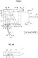
- FIG. 2A is a schematic view illustrating an example of an insulator according to a second embodiment.
- FIG. 2B is a schematic view illustrating an example in a side view of the insulator.
- constituents having the same functions and configurations as in the first embodiment will be given the same reference numerals as in the first embodiment, and descriptions thereof will be omitted.
- an insulator 1 is provided with a third electrical conductor 13a, which is electrically connected to the ground terminal 28, includes a cover portion 133 having a size large enough to cover the first electrical conductor 11 and the second electrical conductor 12 disposed on the main body 10.
- the cover portion 133 is disposed on a layer different from a layer on which the first electrical conductor 11 and the second electrical conductor 12 are disposed so that the cover portion 133 covers the first electrical conductor 11 and the second electrical conductor 12, while maintaining the electrical insulation.
- cover portion 133 preferably covers not less than 70% of the total area of the first electrical conductor 11 and the second electrical conductor 12, as illustrated in FIG. 2A , and more preferably covers not less than 80% of the total area, for example.
- the third electrical conductor 13, which is connected to the ground terminal 28, covers the first electrical conductor 11 and the second electrical conductor 12.
- the insulator 1 serves as a shield against external noise and radiation noise.
Landscapes
- Engineering & Computer Science (AREA)
- Power Engineering (AREA)
- Physics & Mathematics (AREA)
- Electromagnetism (AREA)
- Motor Or Generator Frames (AREA)
Abstract
Description
- The present invention relates to an insulator that is attachable to a motor.
- A wiper control device provided with a wiper motor including a high-speed power supply input terminal, a low-speed power supply input terminal, and a ground terminal is known as a conventional technology (see
Patent Document 1, for example). - Patent Document 1: Japanese Unexamined Patent Application Publication No.
H8-310349A - A conventional wiper motor may be provided with two input terminals and a ground terminal in a configuration in which the two input terminals are disposed close to each other and the ground terminal is disposed at a different location. As such, if electrical wires connected to these two input terminals and the ground terminal are twisted together, a distance from the terminals to a position where the twisted portion of the electrical wires starts become longer, which may cause a problem of radiation noise.
- Accordingly, an object of the present invention is to provide an insulator that reduces radiation noise.
- An aspect of the present invention provides an insulator including a plurality of electrical conductors and a main body, in which one end of each of the plurality of electrically conductors connected to a ground terminal or a plurality of input terminals of a motor, the main body is formed from insulating material, and the other ends of the plurality of electrical conductors are disposed adjacent to each other on the main body in a direction intersecting with a direction of an output shaft of the motor.
- According to the present invention, radiation noise can be reduced.
-
-
FIG. 1 is a schematic view illustrating an example of an insulator according to a first embodiment. -
FIG. 2A is a schematic view illustrating an example of an insulator according to a second embodiment. -
FIG. 2B is a schematic view illustrating an example in a side view of the insulator. - An insulator according to the present embodiment is generally configured to include a plurality of electrical conductors and a main body. One end of each of the electrical conductors is electrically connected to a ground terminal or one of a plurality of input terminals of a motor. The main body is formed from insulating material. The other ends of the plurality of electrical conductors are disposed adjacent to each other on the main body in a direction intersecting with a direction of an output shaft of the motor.
- The insulator reduces the length of the electric wire from the other end of the electrical wire to a position where twisting of the electrical wires starts compared to cases where each of the electrical wires is directly connected to the ground terminal or the input terminals of the motor and twisted together. Thus, this insulator can reduce radiation noise radiated from a portion of the electrical wires from the other ends to the position where the twisting starts.
-
FIG. 1 is a schematic view illustrating an example of an insulator according to a first embodiment.FIG. 1 is a view illustrating an example in which amotor 2 is attached to aninsulator 1. In the drawings associated with the following embodiment, ratios between elements in the drawings may be different from the actual ratios. - Examples of the
motor 2 attached to thisinsulator 1 may include a motor mounted on a vehicle and used as a motor for driving a wiper device or a mirror device. Themotor 2 according to the present embodiment may be a motor for driving the mirror device, for example. Thismotor 2 is provided with aninput terminal 26, aninput terminal 27, and aground terminal 28 as illustrated inFIG. 1 , for example. - The
insulator 1 is, as illustrated inFIG. 1 , generally configured to includeelectrical conductors main body 10. A firstelectrical conductor 11 is electrically connected to theinput terminal 26 of themotor 2 at one end of the firstelectrical conductor 11, a secondelectrical conductor 12 is electrically connected to theinput terminal 27 of themotor 2 at one end of the secondelectrical conductor 12, and a thirdelectrical conductor 13 is electrically connected to theground terminal 28 of themotor 2 at one end of the thirdelectrical conductor 13. Themain body 10 is formed from insulating material, and the other ends of the firstelectrical conductor 11 to the thirdelectrical conductor 13 are disposed adjacent to each other on themain body 10 in a direction intersecting with a direction of anoutput shaft 25 of themotor 2. - The one ends of the first
electrical conductor 11, the second conductor, and the thirdelectrical conductor 13 are anend portion 110, anend portion 120, and anend portion 130, respectively. Also, the other ends of the firstelectrical conductor 11, thesecond conductor 12, and the thirdelectrical conductor 13 are anend portion 111, anend portion 112, and anend portion 131, respectively. - A
harness 4 including aconnector 46, as illustrated inFIG. 1 . is attached to theinsulator 1. Theharness 4 is electrically connected to a battery or the like of a vehicle via theconnector 46. - The
main body 10 is formed using a synthetic resin, for example. Themain body 10 includes anarrangement surface 10a, which is a surface on a back side inFIG. 1 , and is configured so that themotor 2 may be attached to thearrangement surface 10a. Themotor 2 can be attached to thearrangement surface 10a via a holding portion disposed on thearrangement surface 10a. for example. A hook for holding themotor 2 may constitute the holding portion, for example. - The
arrangement surface 10a of themain body 10 is also configured so that the electrical conductors, from the firstelectrical conductor 11 to the thirdelectrical conductor 13, can be attached thereto. As a modified example, themain body 10 may be, for example, formed integrally with the electrical conductors, from the firstelectrical conductor 11 to the thirdelectrical conductor 13, by insert molding, for example. In this case, for example, openings are disposed on aback surface 10b of themain body 10. Through the openings, theend portion 110 of the firstelectrical conductor 11 and theend portion 120 of the secondelectrical conductor 12 are exposed. Bonding between theend portion 110 and theinput terminal 26 and the bonding between theend portion 120 and theinput terminal 27 are performed via the openings. If theend portion 110 and theend portion 120 are configured to be inserted into theinput terminal 26 and theinput terminal 27, the openings are not disposed. - The electrical conductors, from the first
electrical conductor 11 to the thirdelectrical conductor 13, are straight-angle electrical conductors having rectangular-shaped cross-sections, for example. Also, the electrical conductors, from the firstelectrical conductor 11 to the thirdelectrical conductor 13, are formed by punching out a metal plate having an electrical conductivity, such as copper, for example. The electrical conductors, from the firstelectrical conductor 11 to the thirdelectrical conductor 13, have the same width, for example. - The end portions of the electrical conductors, from the
end portion 111 of the firstelectrical conductor 11 to theend portion 131 of the thirdelectrical conductor 13, are arranged adjacent to each other toward aside surface 10c of themain body 10, as illustrated inFIG 1 . The end portions, from theend portion 111 to theend portion 131, are arranged at equal intervals, for example. Preferably, each of the intervals is narrower than the width of each of the electrical conductors, for example. The end portions, from theend portion 111 to theend portion 131, are exposed from themain body 10, for example. Electrical wires, from a firstelectrical wire 41 to a thirdelectrical wire 43, described below are connected to the corresponding end portions, from theend portion 111 to theend portion 131. - The first
electrical conductor 11 includes abending portion 112 that is bent at a substantially right angle. Theinput terminal 26 of themotor 2 is disposed nearest to theside surface 10c. As a result, a total length of the firstelectrical conductor 11, which is connected to theinput terminal 26, is less than a total length of the secondelectrical conductor 12 or a total length of the thirdelectrical conductor 13. If theend portion 110 is configured to be inserted into theinput terminal 26 of themotor 2, theend portion 110 is bent to align in a normal direction of thearrangement surface 10a. - The second
electrical conductor 12 has a bendingportion 122 that is bent at a substantially right angle. Theinput terminal 27 of themotor 2 is disposed second nearest to theside surface 10c, following theinput terminal 26. As a result, a total length of the secondelectrical conductor 12, which is connected to theinput terminal 27, is greater than a total length of the firstelectrical conductor 11 and less than a total length of the thirdelectrical conductor 13. If theend portion 120 is configured to be inserted into theinput terminal 27 of themotor 2, theend portion 120 is bent to align in a normal direction of thearrangement surface 10a. - The third
electrical conductor 13 has a bendingportion 132 that is bent at a substantially right angle. Theground terminal 28 of themotor 2 is disposed farthest from theside surface 10c. As a result, a total length of the thirdelectrical conductor 13, which is connected to theground terminal 28, is greater than a total length of the firstelectrical conductor 11 or a total length of the secondelectrical conductor 12. As illustrated inFIG. 1 , theground terminal 28 is disposed not on asurface 21, on which theinput terminal 26 and theinput terminal 27 are disposed, but on aside surface 22a, which meets thesurface 21. As a result, theend portion 130 is bent so as to be easily bonded with theground terminal 28. - Examples of the
motor 2 include a DC motor. Themain body 20 of themotor 2 includes, for example, thesurface 21, on which theinput terminal 26 and theinput terminal 27 are disposed, and a back surface of thesurface 21, each having a flat surface, and further includes aside surface 22a and aside surface 22b, each connecting thesurface 21 and the back surface and having a curved surface. For example, themotor 2 is configured to rotate in one direction if electrical power is applied to theinput terminal 26 and to rotate in a reverse direction, opposite to the direction above, if electrical power is applied to theinput terminal 27. - The
motor 2 includes, as illustrated inFIG. 1 , theoutput shaft 25 near afront surface 23. Themotor 2 also includes theinput terminal 26 and theinput terminal 27 on thesurface 21 near arear surface 24. Theground terminal 28 is disposed on theside surface 22b different from thesurface 21. - A general configuration of the
harness 4 includes electrical conductors, from a firstelectrical wire 41 to a thirdelectrical wire 43, and aconnector 46. Each of the electrical conductors, from firstelectrical wire 41 to the thirdelectrical wire 43, is a twisted wire, and the periphery of the twisted wire is coated with insulating material, for example. Each of the electrical wires, from the firstelectrical wire 41 to the thirdelectrical wire 43, is electrically connected to themotor 2 at one end thereof via theinsulator 1 and electrically connected to theconnector 46 at the other end thereof. - The first
electrical wire 41 is electrically connected to theend portion 111 of the firstelectrical conductor 11. Thus, the firstelectrical wire 41 is electrically connected to theinput terminal 26 via the firstelectrical conductor 11. - The second
electrical wire 42 is electrically connected to theend portion 121 of the secondelectrical conductor 12. Thus, the secondelectrical wire 42 is electrically connected to theinput terminal 27 via the secondelectrical conductor 12. - The third
electrical wire 43 is electrically connected to theend portion 131 of the thirdelectrical conductor 13. Thus, the thirdelectrical wire 43 is electrically connected to theground terminal 28 via the thirdelectrical conductor 13. - The electrical wires, from the first
electrical wire 41 to the thirdelectrical wire 43, as illustrated inFIG.1 , include atwisted portion 45 in which the electrical wires, from the firstelectrical wire 41 to the thirdelectrical wire 43, are integrally twisted. A length of the firstelectrical wire 41 from the twistedportion 45 to the firstelectrical conductor 11, a length of the secondelectrical wire 42 from the twistedportion 45 to the secondelectrical conductor 12, and a length of the thirdelectrical wire 43 from the twistedportion 45 to the thirdelectrical conductor 13 are less than a length from a twisted portion to theinput terminal 26, theinput terminal 27, and theground terminal 28 in the case where each of the electrical wires, from the firstelectrical wire 41 to the thirdelectrical wire 43, is directly connected to theinput terminal 26, theinput terminal 27, and theground terminal 28, respectively. This results from the fact that theinput terminal 26, theinput terminal 27, and theground terminal 28 are separated from each other. - In the
insulator 1, the electrical conductors, from the firstelectrical conductor 11 to the thirdelectrical conductor 13, are electrically connected to theinput terminal 26, theinput terminal 27, and theground terminal 28. As a result, the electrical wires, from the firstelectrical wire 41 to the thirdelectrical wire 43, may be connected to the end portions, from theend portion 111 to theend portion 131, that are arranged adjacent to each other. Thus, it is possible to shorten a length of an untwistedportion 44 that is a portion of the electrical wires from the twistedportion 45 to each of the end portions, from theend portion 111 to theend portion 131. The untwistedportion 44 is a portion in which the electrical wires are not twisted. - The untwisted
portion 44 easily induces radiation noise caused by current driving themotor 2 compared to the twistedportion 45. Thus, a shorter untwistedportion 44 can reduce radiation noise. - The
insulator 1 according to the present embodiment can reduce radiation noise. Specifically, in theinsulator 1, the length of the untwistedportion 44 is short compared to cases where each of the electrical wires is directly connected to a ground terminal or input terminals and twisted. Thus, theinsulator 1 of the present embodiment can reduce radiation noise. - In the
insulator 1, the thirdelectrical conductor 13, which is connected to theground terminal 28, is disposed adjacent to the firstelectrical conductor 11 and the secondelectrical conductor 12, which are connected to theinput terminal 26 and theinput terminal 27, respectively. As a result, the arrangement can reduce the occurrence of radiation noise and is less influenced by external noise compared to the case where this configuration is not adopted. - A second embodiment is different from the first embodiment in that a third electrical conductor, which is connected to the ground terminal, covers other electrical conductors.
-
FIG. 2A is a schematic view illustrating an example of an insulator according to a second embodiment.FIG. 2B is a schematic view illustrating an example in a side view of the insulator. In the embodiment described below, constituents having the same functions and configurations as in the first embodiment will be given the same reference numerals as in the first embodiment, and descriptions thereof will be omitted. - As illustrated in
FIG. 2A , aninsulator 1 according to the present embodiment is provided with a thirdelectrical conductor 13a, which is electrically connected to theground terminal 28, includes acover portion 133 having a size large enough to cover the firstelectrical conductor 11 and the secondelectrical conductor 12 disposed on themain body 10. As illustrated inFIG. 2B , thecover portion 133 is disposed on a layer different from a layer on which the firstelectrical conductor 11 and the secondelectrical conductor 12 are disposed so that thecover portion 133 covers the firstelectrical conductor 11 and the secondelectrical conductor 12, while maintaining the electrical insulation. - Note that the
cover portion 133 preferably covers not less than 70% of the total area of the firstelectrical conductor 11 and the secondelectrical conductor 12, as illustrated inFIG. 2A , and more preferably covers not less than 80% of the total area, for example. - In the
insulator 1 according to the present embodiment, the thirdelectrical conductor 13, which is connected to theground terminal 28, covers the firstelectrical conductor 11 and the secondelectrical conductor 12. Thus theinsulator 1 serves as a shield against external noise and radiation noise. Thus, this configuration can reduce radiation noise and is less influenced by external noise compared to the case where this configuration is not adopted. - Although several embodiments of the present invention and a modified example thereof have been described above, these embodiments and modified example are merely examples, and the invention according to claims is not intended to be limited thereto. Such novel embodiments and a modified example can be implemented in various other forms, and various omissions, substitutions, changes, and the like can be made without departing from the spirit and scope of the present invention. In addition, all combinations of the features described in these embodiments and modified example are not necessary to solve the problem. Furthermore, these embodiments and modified example are included within the spirit and scope of the invention and also within the invention described in the claims and the scope of equivalents thereof.
Claims (7)
- An insulator, comprising a plurality of electrical conductors and a main body,wherein one ends of the plurality of electrical conductors are electrically connected to a ground terminal or a plurality of input terminals of a motor,the main body comprises an insulating material, andother ends of the plurality of electrical conductors are disposed adjacent to each other on the main body in a direction intersecting with a direction of an output shaft of the motor.
- The insulator according to claim 1, wherein one of the plurality of electrical conductors electrically connected to the ground terminal comprises a cover portion having a size large enough to cover another electrical conductor disposed on the main body, andwherein the cover portion is disposed on a layer different from a layer on which the another electrical conductor is disposed and covers the another electrical conductor and maintaining electrical insulation.
- The insulator according to claim 1 or 2, wherein the other ends of the plurality of electrical conductors are electrically connected to plurality of electrical wires,wherein the plurality of electrical wires comprise a twisted portion in which the plurality of electrical wires are integrally twisted, andwherein lengths of the plurality of electrical wires from the twisted portion to the electrical conductors are each less than lengths of the plurality of electrical wires from a twisted portion to the ground terminal and the input terminals in the case where the plurality of electrical wires are directly connected to the ground terminal and the plurality of input terminals and twisted.
- The insulator according to any one of claims 1 to 3, wherein the plurality of electrical conductors are exposed from the main body at the other ends.
- The insulator according to any one of claims 1 to 4, wherein the plurality of electrical conductors are integrally formed with the main body.
- The insulator according to any one of claims 1 to 5, wherein the plurality of electrical conductors are insulated each other by the insulating material in between the one ends and the other ends.
- The insulator according to any one of claims 1 to 6, wherein the plurality of electrical conductors are arranged parallel to each other in between the one ends and the other ends.
Applications Claiming Priority (1)
| Application Number | Priority Date | Filing Date | Title |
|---|---|---|---|
| JP2016013031A JP6334581B2 (en) | 2016-01-27 | 2016-01-27 | Insulator |
Publications (1)
| Publication Number | Publication Date |
|---|---|
| EP3200325A1 true EP3200325A1 (en) | 2017-08-02 |
Family
ID=57944280
Family Applications (1)
| Application Number | Title | Priority Date | Filing Date |
|---|---|---|---|
| EP17153305.2A Withdrawn EP3200325A1 (en) | 2016-01-27 | 2017-01-26 | Insulator |
Country Status (4)
| Country | Link |
|---|---|
| US (1) | US10403988B2 (en) |
| EP (1) | EP3200325A1 (en) |
| JP (1) | JP6334581B2 (en) |
| CN (1) | CN107070065B (en) |
Citations (5)
| Publication number | Priority date | Publication date | Assignee | Title |
|---|---|---|---|---|
| JPH08310349A (en) | 1995-05-23 | 1996-11-26 | Nippondenso Co Ltd | Wiper controller |
| JP2001008400A (en) * | 1999-06-18 | 2001-01-12 | Akebono Brake Ind Co Ltd | Motor device and motor-driven brake using the same |
| EP1416614A1 (en) * | 2002-11-04 | 2004-05-06 | Siemens Aktiengesellschaft | Connection adapter for electric motor |
| CN203554135U (en) * | 2013-10-22 | 2014-04-16 | 常州市常华电机有限公司 | Three-phase hybrid stepping motor |
| US20150235741A1 (en) * | 2014-02-19 | 2015-08-20 | Hitachi Metals, Ltd. | Noise Suppression Cable |
Family Cites Families (37)
| Publication number | Priority date | Publication date | Assignee | Title |
|---|---|---|---|---|
| US1416614A (en) * | 1913-11-28 | 1922-05-16 | Cournand Jules | Syringe with progressively-graduated automatic action |
| JPS5274497A (en) * | 1975-12-11 | 1977-06-22 | Tange F | Binder |
| US4043362A (en) * | 1976-02-09 | 1977-08-23 | Gardner-Denver Company | Cutting and insulation stripping apparatus for twisted wire pair |
| US4258969A (en) * | 1979-11-19 | 1981-03-31 | Stallard Jerrel L | Reversing plug connector |
| US4336975A (en) * | 1980-03-27 | 1982-06-29 | Casteel Ronald C | Automotive electrical harness |
| JPS5868686A (en) | 1981-10-20 | 1983-04-23 | Nec Corp | Dial type electronic time piece |
| JPS5868686U (en) * | 1981-11-04 | 1983-05-10 | 松下精工株式会社 | Grounding device for power terminal board |
| US4642885A (en) * | 1984-02-15 | 1987-02-17 | General Electric Company | Method of assembling a stator |
| JPS60237843A (en) * | 1984-05-08 | 1985-11-26 | Matsushita Electric Ind Co Ltd | Commutator motor |
| GB2203600A (en) * | 1987-04-13 | 1988-10-19 | Johnson Electric Ind Mfg | A device for connecting a wire to a terminal |
| JPH02174080A (en) * | 1988-12-27 | 1990-07-05 | Matsushita Seiko Co Ltd | Earth fitting device for fan |
| EP0535632A3 (en) * | 1991-10-01 | 1993-05-19 | Japan Magnetic Lock Co., Ltd. | Burglarproof system for automotive vehicle |
| US5245237A (en) * | 1992-03-19 | 1993-09-14 | General Electric Company | Two compartment motor |
| US5852338A (en) * | 1997-02-03 | 1998-12-22 | General Electric Company | Dynamoelectric machine and method for manufacturing same |
| JPH07272798A (en) * | 1994-03-31 | 1995-10-20 | Oki Electric Ind Co Ltd | Shield structure for terminal of connector |
| US6107710A (en) * | 1996-02-12 | 2000-08-22 | Gamboa; Jose | Alternator rectifier assembly connection conversion means and method |
| JP3099741B2 (en) * | 1996-07-16 | 2000-10-16 | 三菱マテリアル株式会社 | Micro motor |
| US6040646A (en) * | 1999-01-22 | 2000-03-21 | A. O. Smith Corporation | Plug for changing an operating condition of an electric motor |
| JP2001286090A (en) * | 2000-03-30 | 2001-10-12 | Minebea Co Ltd | Motor terminal structure |
| US6664682B2 (en) * | 2001-02-28 | 2003-12-16 | Reliance Electric Technologies, Llc | Method and apparatus for securing a conduit box to a motor and motor incorporating same |
| ITPD20010016U1 (en) * | 2001-03-01 | 2002-09-02 | Inarca Spa | DEVICE FOR THE CONNECTION AND INSULATION OF A THERMAL PROTECTOR FOR ELECTRIC WINDINGS OF MOTORS. |
| JP4032723B2 (en) | 2001-12-06 | 2008-01-16 | 松下電器産業株式会社 | Air conditioner |
| US6856056B2 (en) * | 2002-07-24 | 2005-02-15 | Emerson Electric Co. | Three phase electric motor terminal box mounted connection board |
| JP2004153891A (en) * | 2002-10-29 | 2004-05-27 | Mitsubishi Electric Corp | Rotating electric machine |
| US6882070B2 (en) * | 2003-04-01 | 2005-04-19 | A. O. Smith Corporation | Electric motor having a terminal board |
| JP2005229721A (en) * | 2004-02-12 | 2005-08-25 | Mitsubishi Electric Corp | Electric power steering motor |
| FR2874414B1 (en) * | 2004-08-17 | 2009-04-03 | Valeo Climatisation Sa | SUPPORT EQUIPPED WITH VIBRATION ABSORPTION MEANS FOR A PULSE ENGINE |
| JP2006288010A (en) * | 2005-03-31 | 2006-10-19 | Sanyo Electric Co Ltd | Vibrating motor |
| JP4502912B2 (en) * | 2005-09-16 | 2010-07-14 | 三菱電機株式会社 | Rotating electric machine and manufacturing method thereof |
| JP4931498B2 (en) * | 2006-07-12 | 2012-05-16 | 株式会社デンソー | Motor equipment |
| US7772731B2 (en) * | 2007-03-16 | 2010-08-10 | Keihin Corporation | Electric motor, rotary actuator and rotary apparatus |
| JP5095439B2 (en) * | 2008-02-19 | 2012-12-12 | リコーエレメックス株式会社 | Motors and electronic devices |
| JP5554763B2 (en) * | 2011-10-17 | 2014-07-23 | シナノケンシ株式会社 | Outer rotor type motor |
| JP5944169B2 (en) * | 2012-01-20 | 2016-07-05 | サンデンホールディングス株式会社 | Electric compressor |
| KR102128452B1 (en) * | 2013-10-02 | 2020-06-30 | 엘지이노텍 주식회사 | Motor |
| US9680355B2 (en) * | 2014-01-03 | 2017-06-13 | Carter Fuel Systems, Llc | Grounding device for brushless electric motor |
| DE102014220201A1 (en) * | 2014-10-06 | 2016-04-07 | Bühler Motor GmbH | Electronically commutated DC motor, in particular for an oil pump |
-
2016
- 2016-01-27 JP JP2016013031A patent/JP6334581B2/en not_active Expired - Fee Related
- 2016-12-09 CN CN201611128235.4A patent/CN107070065B/en not_active Expired - Fee Related
-
2017
- 2017-01-24 US US15/414,228 patent/US10403988B2/en active Active
- 2017-01-26 EP EP17153305.2A patent/EP3200325A1/en not_active Withdrawn
Patent Citations (5)
| Publication number | Priority date | Publication date | Assignee | Title |
|---|---|---|---|---|
| JPH08310349A (en) | 1995-05-23 | 1996-11-26 | Nippondenso Co Ltd | Wiper controller |
| JP2001008400A (en) * | 1999-06-18 | 2001-01-12 | Akebono Brake Ind Co Ltd | Motor device and motor-driven brake using the same |
| EP1416614A1 (en) * | 2002-11-04 | 2004-05-06 | Siemens Aktiengesellschaft | Connection adapter for electric motor |
| CN203554135U (en) * | 2013-10-22 | 2014-04-16 | 常州市常华电机有限公司 | Three-phase hybrid stepping motor |
| US20150235741A1 (en) * | 2014-02-19 | 2015-08-20 | Hitachi Metals, Ltd. | Noise Suppression Cable |
Also Published As
| Publication number | Publication date |
|---|---|
| US20170214157A1 (en) | 2017-07-27 |
| JP6334581B2 (en) | 2018-05-30 |
| JP2017135820A (en) | 2017-08-03 |
| CN107070065B (en) | 2020-02-07 |
| US10403988B2 (en) | 2019-09-03 |
| CN107070065A (en) | 2017-08-18 |
Similar Documents
| Publication | Publication Date | Title |
|---|---|---|
| EP2584664B1 (en) | Integrated-type shield protector and wire harness | |
| US9236720B2 (en) | High voltage conductive wire and wire harness | |
| US10532706B2 (en) | Conductive wire and wire harness | |
| EP2533376A1 (en) | Crimped connection structure | |
| US11749925B2 (en) | Assembled electrical cable, method for assembling an electrical cable, and electrical plug connection | |
| US10596983B2 (en) | Wire harness | |
| CN114447664B (en) | Connector and connector with electric wire comprising the same | |
| CN108370121B (en) | Shielded connectors and shielded cables with connectors | |
| US10411370B2 (en) | High-voltage cable set | |
| CN103477413B (en) | fuse unit | |
| CN105452064B (en) | Wiring structure of power supply wire to heating wire terminal | |
| US10770200B2 (en) | Shielded conductive path | |
| US9012777B2 (en) | Conductive path structure and wire harness | |
| JP2012074180A (en) | Connection structure of fiber conductor | |
| US10403988B2 (en) | Motor insulator for reducing radiation noise | |
| JP6158539B2 (en) | Electric wire branching structure | |
| JPWO2015030011A1 (en) | Shielded wire and wire harness | |
| JP2022111646A (en) | Wiring harness | |
| US20160035528A1 (en) | Fuse unit | |
| CN110323582A (en) | Electric wire with terminal | |
| CN116867684A (en) | Cable connection with improved electromagnetic shielding | |
| EP3683806A1 (en) | Cable conductor | |
| US20160163423A1 (en) | Shielded wire and wire harness | |
| KR102115510B1 (en) | Electric terminal and motor comprising the same | |
| KR101473999B1 (en) | Terminal for aluminum cable |
Legal Events
| Date | Code | Title | Description |
|---|---|---|---|
| PUAI | Public reference made under article 153(3) epc to a published international application that has entered the european phase |
Free format text: ORIGINAL CODE: 0009012 |
|
| AK | Designated contracting states |
Kind code of ref document: A1 Designated state(s): AL AT BE BG CH CY CZ DE DK EE ES FI FR GB GR HR HU IE IS IT LI LT LU LV MC MK MT NL NO PL PT RO RS SE SI SK SM TR |
|
| AX | Request for extension of the european patent |
Extension state: BA ME |
|
| 17P | Request for examination filed |
Effective date: 20180202 |
|
| RBV | Designated contracting states (corrected) |
Designated state(s): AL AT BE BG CH CY CZ DE DK EE ES FI FR GB GR HR HU IE IS IT LI LT LU LV MC MK MT NL NO PL PT RO RS SE SI SK SM TR |
|
| STAA | Information on the status of an ep patent application or granted ep patent |
Free format text: STATUS: THE APPLICATION HAS BEEN WITHDRAWN |
|
| 18W | Application withdrawn |
Effective date: 20181025 |