EP3200300B1 - Electronic trip unit protection device and protection method - Google Patents
Electronic trip unit protection device and protection method Download PDFInfo
- Publication number
- EP3200300B1 EP3200300B1 EP15844951.2A EP15844951A EP3200300B1 EP 3200300 B1 EP3200300 B1 EP 3200300B1 EP 15844951 A EP15844951 A EP 15844951A EP 3200300 B1 EP3200300 B1 EP 3200300B1
- Authority
- EP
- European Patent Office
- Prior art keywords
- circuit
- storage capacitor
- energy storage
- power supply
- output
- Prior art date
- Legal status (The legal status is an assumption and is not a legal conclusion. Google has not performed a legal analysis and makes no representation as to the accuracy of the status listed.)
- Active
Links
Images


Classifications
-
- H—ELECTRICITY
- H01—ELECTRIC ELEMENTS
- H01H—ELECTRIC SWITCHES; RELAYS; SELECTORS; EMERGENCY PROTECTIVE DEVICES
- H01H71/00—Details of the protective switches or relays covered by groups H01H73/00 - H01H83/00
- H01H71/10—Operating or release mechanisms
- H01H71/12—Automatic release mechanisms with or without manual release
- H01H71/42—Induction-motor, induced-current, or electrodynamic release mechanisms
- H01H71/43—Electrodynamic release mechanisms
-
- H—ELECTRICITY
- H02—GENERATION; CONVERSION OR DISTRIBUTION OF ELECTRIC POWER
- H02H—EMERGENCY PROTECTIVE CIRCUIT ARRANGEMENTS
- H02H1/00—Details of emergency protective circuit arrangements
- H02H1/06—Arrangements for supplying operative power
-
- H—ELECTRICITY
- H02—GENERATION; CONVERSION OR DISTRIBUTION OF ELECTRIC POWER
- H02H—EMERGENCY PROTECTIVE CIRCUIT ARRANGEMENTS
- H02H3/00—Emergency protective circuit arrangements for automatic disconnection directly responsive to an undesired change from normal electric working condition with or without subsequent reconnection ; integrated protection
- H02H3/08—Emergency protective circuit arrangements for automatic disconnection directly responsive to an undesired change from normal electric working condition with or without subsequent reconnection ; integrated protection responsive to excess current
-
- H—ELECTRICITY
- H01—ELECTRIC ELEMENTS
- H01H—ELECTRIC SWITCHES; RELAYS; SELECTORS; EMERGENCY PROTECTIVE DEVICES
- H01H71/00—Details of the protective switches or relays covered by groups H01H73/00 - H01H83/00
- H01H71/10—Operating or release mechanisms
- H01H71/50—Manual reset mechanisms which may be also used for manual release
- H01H71/52—Manual reset mechanisms which may be also used for manual release actuated by lever
- H01H71/522—Manual reset mechanisms which may be also used for manual release actuated by lever comprising a cradle-mechanism
- H01H71/525—Manual reset mechanisms which may be also used for manual release actuated by lever comprising a cradle-mechanism comprising a toggle between cradle and contact arm and mechanism spring acting between handle and toggle knee
Definitions
- the present invention relates to low-voltage electric apparatuses, more particularly, relates to circuit breakers of low-voltage electric apparatuses.
- a core component of an electronic circuit breaker is an electronic release.
- An execution mechanism of the electronic release is generally a magnetic flux converter.
- the magnetic flux converter comprises a magnetic flux converter coil, a permanent magnet, a counter-force spring, an ejector rod etc,.
- a primary loop i.e. the main loop or the load circuit
- the magnetic flux converter remains in an attraction status, the permanent magnet attracts the ejector rod so that the ejector rod will not trigger a release mechanism.
- a magnetic force of the permanent magnet is larger than a spring force of the counter-force spring. No current flows through the magnetic flux converter coil and no electromagnetic force is generated.
- the permanent magnet attracts the ejector rod by its magnetic force, and the circuit breaker remains closed.
- a primary loop i.e. the main loop or the load circuit
- a circuit composed of an energy storage capacitor and the magnetic flux converter coil within the electronic release is closed.
- the energy storage capacitor discharges the stored electrical energy and forms a current flowing through the magnetic flux converter coil.
- the current causes a generation of an electromagnetic force in the magnetic flux converter coil.
- the electromagnetic force and the spring force of the counter-force spring are in the same direction, and are opposite to the magnetic force of the permanent magnet. A sum of the electromagnetic force and the spring force is larger than the magnetic force of the permanent magnet.
- the ejector rod is released and ejected out, and the ejector rod triggers the release mechanism, the circuit breaker is disconnected and the primary loop is cut off.
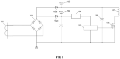
- FIG. 1 illustrates a principle diagram of an electronic release according to prior art.
- the electronic release comprises a current transformer 101, a filtering and rectification circuit 109, a control power supply circuit 102, a release power supply circuit 103, a control circuit composed of a step-down circuit 104 and a MCU unit 105, and a release circuit composed of an energy storage capacitor 106, a magnetic flux converter 107 and a control switch 108.
- the current transformer 101 is connected in series in a primary loop.
- the current transformer 101 generates an induced current from the primary loop current.
- the filtering and rectification circuit 109 is connected to an output of the current transformer 101.
- the filtering and rectification circuit 109 filters and rectifies the induced current of the current transformer.
- An output of the filtering and rectification circuit 109 is divided into two paths, which are connected to the control power supply circuit 102 and the release power supply circuit 103 respectively. Inputs of the control power supply circuit 102 and the release power supply circuit 103 are both connected to the output of the filtering and rectification circuit 109.
- the control power supply circuit 102 and the release power supply circuit 103 each comprises a diode 102a and 103a, respectively.
- the control circuit comprises a step-down circuit 104 and a MCU unit 105.
- the step-down circuit 104 is connected to an output of the control power supply circuit 103.
- the step-down circuit 104 reduces an output voltage of the control power supply circuit 103 to a rated operation voltage of the MCU unit 105.
- the MCU unit 105 is connected to an output of the step-down circuit 104 and is supplied by the step-down circuit 104.
- the MCU unit 105 also receives a monitoring signal indicating whether a fault exists in the primary loop.
- the monitoring signal is connected to a signal I/O end of the MCU unit 105.
- FIG. 1 focuses on a current loop rather than a signal loop, so the monitoring signal for the primary loop is not shown in FIG. 1 .
- the release circuit comprises an energy storage capacitor 106, a magnetic flux converter 107 and a control switch 108 which are connected in series.
- the output of the release power supply circuit 103 is connected to the energy storage capacitor 106, the output of the MCU unit is connected to the control switch 108 to turn on or off the control switch.
- the energy storage capacitor 106, the magnetic flux converter 107 and the control switch 108 form a complete loop, that is, the release circuit.
- the MCU unit 105 controls the control switch 108 to turn off and the release circuit is turned off.
- the release power supply circuit 103 charges the energy storage capacitor 106.
- the MCU unit 105 outputs a release instruction to turn on the control switch 108, the release circuit is turned on.
- the energy storage capacitor 106 discharges and causes an appearance of a current in a coil of the magnetic flux converter 107. This current generates an electromagnetic force, which assists a counter-force springs of the magnetic flux converter to overcome a magnetic force of a permanent magnet, so that an ejector rod is ejected out and drives a release mechanism to operate and break a circuit breaker.
- the electronic release shall work reliably and achieve basic protection functions when all phase currents in the primary loop (the main loop) are not less than 0.4 times of a rated current, that is, 0.4 In.
- a rated current that is, 0.4 In.
- an induced current generated by the current transformer 101 is used as two purposes, on one hand, normal operation of the MCU unit is met, and on the other hand, the energy storage capacitor is charged. Normal operation of the MCU unit is preferentially considered. The induced current is preferentially used for supplying power for the MCU, and an extra current is used to charge the energy storage capacitor.
- the induced current is also large and can meet both purposes at a same time.
- the current in the primary loop is small, especially when it is close to the lower limit of the national standard, that is, 0.4 In, the induced current generated by the current transformer is also small, then normal operation of the MCU unit is preferentially met. Since the control circuit connected to a rear end of the control power supply circuit has a heavy load, the current is mainly distributed to the control circuit, and the output current of the release power supply circuit is small, which will cause an insufficient charging of the energy storage capacitor and the energy capacitor cannot be charged to an enough voltage.
- the energy storage capacitor needs to be charged to 12V ⁇ 15V to ensure that the current in the coil of the magnetic flux converter is large enough, so that the overlapped electromagnetic force generated by the current and the spring force of the counter-force spring can be larger than the magnetic force of the permanent magnet.
- an insufficient charging of the energy storage capacitor such as lower than 12V
- the energy storage capacitor discharges and generates a current in the coil of the magnetic flux converter.
- the electromagnetic force generated by the current is not large enough, the magnetic force of the permanent magnet is still larger than summary of the electromagnetic force and the spring force of the counter-force spring.
- the ejector rod is still attracted and cannot be ejected out, the release mechanism does not operate and the circuit breaker is not broken.
- US 2008/012667 A1 describes a time-synchronized trip implementation for a motor circuit protector (MCP) having a reconfigurable microcontroller.
- MCP motor circuit protector
- the microcontroller causes a power supply to be charged for an initial time period during a charging mode.
- a control algorithm charges a stored energy circuit from a minimum voltage regulation level to a voltage level indicative of sufficient energy to actuate a trip solenoid.
- the charging of capacitors is regulated by a voltage regulation module, which holds the stored energy circuit in the charge mode until a start voltage threshold level is reached for the supply voltage from the stored energy circuit.
- An onboard comparator is configured for a predetermined self-protection level of the MCP, and fault currents that exceed the comparator's threshold will directly drive a solenoid to trip the MCP.
- the microcontroller reconfigures the comparator's threshold to both measure and charge the power supply toward a stored energy trip voltage, which will charge quickly when high fault currents are present. As a result, self-protection is not compromised.
- the microcontroller reconfigures the onboard comparator's threshold for self-protection trip levels. When a trip event occurs in this mode, stored energy trip activation occurs.
- the MCP includes user-selectable trip settings, and the microcontroller reconfigures the comparator threshold levels for user-selectable self-protection levels.
- the present invention provides a protection system and a protection method that can charge an energy storage capacitor to a sufficient voltage when the current in the primary loop is a small current.
- a protection system for electronic release comprises an electronic release including an energy storage capacitor, a control power supply circuit, and a MCU unit.
- the protection system further comprises a protection device connected to the energy storage capacitor of the electronic release.
- the control power supply circuit is configured to charge the energy storage capacitor to a sufficient voltage when a primary loop current is a small current.
- the small current is 0.4 ⁇ 0.8 times of a rated primary loop current, and the sufficient voltage is 12V ⁇ 15V.
- the control power supply circuit is configured to provide the energy storage capacitor with an additional charge supplied by extra electrical energy exceeding the electrical energy needed for a normal operation of the MCU unit.
- the electronic release further comprises a current transformer, a filtering and rectification circuit, a control power supply circuit, a release power supply circuit, a control circuit and a release circuit.
- the current transformer is connected in series in a primary loop and generating an induced current from the primary loop current.
- the filtering and rectification circuit is connected to an output of the current transformer, the filtering and rectification circuit filters and rectifies the induced current of the current transformer.
- the control power supply circuit is connected to an output of the filtering and rectification circuit.
- the release power supply circuit is connected to the output of the filtering and rectification circuit.
- the control circuit comprises a step-down circuit and the MCU unit, the step-down circuit is connected to an output of the control power supply circuit and reduces an output voltage of the control power supply circuit.
- the MCU unit is connected to an output of the step-down circuit and is supplied by the step-down circuit.
- the release circuit comprises the energy storage capacitor, a magnetic flux converter and a control switch which are connected in series.
- the output of the control power supply circuit is connected to the energy storage capacitor.
- the output of the MCU unit is connected to the control switch to turn on or off the control switch.
- the MCU unit controls the control switch to turn off and the release circuit is turned off, the release power supply circuit charges the energy storage capacitor.
- the MCU unit outputs a release instruction to turn on the control switch, the release circuit is turned on, the energy storage capacitor discharges to enable the magnetic flux converter to generate an electromagnetic force and trigger a release mechanism.
- the protection device comprises a resistor, a boost circuit and a diode which are connected in series, a first end of the resistor is connected to the control power supply circuit, a second end of the resistor is connected to an input of the boost circuit, an output of the boost circuit is connected to the energy storage capacitor through the diode, the output of the diode is connected to the MCU unit.
- the output of the control power supply circuit is provided to the MCU unit, and the extra electrical energy is used to charge the energy storage capacitor through the protection device.
- the protection device comprises a rechargeable battery circuit and a PWM charging circuit.
- the rechargeable battery circuit comprises a charging circuit and a rechargeable battery, an input of the charging circuit is connected to the output of the step-down circuit, an output of the charging circuit is connected to the rechargeable battery through a diode.
- the PWM charging circuit comprises a control circuit and a boost circuit, an input of the control circuit is connected to an output of the rechargeable battery, an output of the control circuit is connected to an input of the boost circuit, an enabling end of the control circuit is connected to the MCU unit, an output of the boost circuit is connected to the energy storage capacitor through a diode.
- an output of the step-down circuit charges the rechargeable battery
- the MCU unit outputs a duty cycle signal to the control circuit
- the control circuit enables the rechargeable battery to charge the energy storage capacitor in a PWM mode according to the duty cycle signal.
- a charging time of the energy storage capacitor is determined by the duty cycle signal, the duty cycle signal is related to a fault type of the electronic release.
- a protection method for electronic release comprises providing an electronic release comprising an energy storage capacitor, control power supply circuit, and a MCU unit.
- the method further comprises providing a protection device connected to the energy storage capacitor.
- the method further comprises providing additional charge to the energy storage capacitor of the electronic release, charging the energy storage capacitor to a sufficient voltage when a primary loop current is a small current.
- the small current is 0.4 ⁇ 0.8 times of a rated primary loop current, and the sufficient voltage is 12V ⁇ 15V.
- the additional charge provided to the energy storage capacitor is supplied by extra electrical energy that exceeds the electrical energy needed for a normal operation of the MCU unit of the electronic release.
- the protection device comprises a resistor, a boost circuit and a diode which are connected in series, a first end of the resistor is connected to the control power supply circuit, a second end of the resistor is connected to an input of the boost circuit, an output of the boost circuit is connected to the energy storage capacitor through the diode, the output of the diode is connected to the MCU unit.
- the protection method further comprises providing output of the control power supply circuit to the MCU unit, and using the extra electrical energy to charge the energy storage capacitor through the protection device.
- the extra electrical energy is outputted from a control power supply circuit of the electronic release, and is used to charge the energy storage capacitor in a direct-current manner after resistance current-limiting and boosting.
- the additional charge is supplied by a rechargeable battery
- the rechargeable battery is charged by the extra electrical energy
- the MCU unit outputs a duty cycle signal according to a fault type of the electronic release
- the rechargeable battery charges the energy storage capacitor in a PWM mode through a control circuit and a boost circuit based on the duty cycle.
- the protection system and the protection method for electronic release of the present invention charge the energy storage capacitor with extra electrical energy that exceeds the electrical energy needed for a normal operation of a MCU unit.
- the energy storage capacitor can still be charged to a sufficient voltage when the current in the primary loop is a small current, so that the magnetic flux converter can generate an electromagnetic force that is large enough to trigger the release mechanism.
- the present invention provides a protection system for electronic release comprising an electronic release including an energy storage capacitor and a MCU unit.
- the protection system further comprises a protection device connected to an energy storage capacitor of the electronic release.
- the energy storage capacitor is charged to a sufficient voltage when a primary loop current is a small current.
- the small current is 0.4 ⁇ 0.8 times of a rated primary loop current and the sufficient voltage is 12V ⁇ 15V.
- the energy storage capacitor is provided with an additional charge supplied by extra electrical energy exceeding the electrical energy needed for a normal operation of the MCU unit.
- the small current is 0.4 ⁇ 0.5 times of the rated primary loop current. Even, in some embodiments, the small current is 0.4 ⁇ 0.45 times of the rated primary loop current.
- FIG. 2 illustrates a principle diagram of a protection system according to an embodiment of the present invention.
- the energy storage capacitor is charged by a direct boost charging mode with resistance current-limiting, and the energy storage capacitor is charged by extra electrical energy that exceeds the electrical energy needed for a normal operation of a MCU unit.
- the electronic release comprises a current transformer 201, a filtering and rectification circuit 209, a control power supply circuit 202, a release power supply circuit 203, a control circuit and a release circuit.
- the current transformer 201 is connected in series in a primary loop.
- the current transformer 201 generates an induced current from the primary loop current.
- the filtering and rectification circuit 209 is connected to an output of the current transformer 201.
- the filtering and rectification circuit 209 filters and rectifies the induced current of the current transformer.
- An output of the filtering and rectification circuit 209 is divided into two paths, which are connected to the control power supply circuit 202 and the release power supply circuit 203 respectively. Inputs of the control power supply circuit 202 and the release power supply circuit 203 are both connected to the output of the filtering and rectification circuit 209.
- the control power supply circuit 202 and the release power supply circuit 203 each comprises a diode 202a and 203a, respectively.
- the control circuit comprises a step-down circuit 204 and a MCU unit 205.
- the step-down circuit 204 is connected to an output of the control power supply circuit 202.
- the step-down circuit 204 reduces an output voltage of the control power supply circuit 202 to a rated operation voltage of the MCU unit 205.
- the MCU unit 205 is connected to an output of the step-down circuit 204 and is supplied by the step-down circuit 204.
- the MCU unit 205 also receives a monitoring signal indicating whether a fault exists in the primary loop.
- the release circuit comprises an energy storage capacitor 206, a magnetic flux converter 207 and a control switch 208 which are connected in series.
- the output of the release power supply circuit 203 is connected to the energy storage capacitor 206, the output of the MCU unit is connected to the control switch 208 to turn on or off the control switch.
- the energy storage capacitor 206, the magnetic flux converter 207 and the control switch 208 form a complete loop, that is, the release circuit.
- the MCU unit 205 controls the control switch 208 to turn off and the release circuit is turned off.
- the release power supply circuit 203 charges the energy storage capacitor 206.
- the MCU unit 205 outputs a release instruction to turn on the control switch 208, the release circuit is turned on.
- FIG. 2 further comprises a protection device.
- the protection device shown in FIG. 2 comprises a resistor 210, a boost circuit 211 and a diode 214 which are connected in series.
- a first end of the resistor 210 is connected to the control power supply circuit 202, a second end of the resistor 210 is connected to an input of the boost circuit 211.
- An output of the boost circuit 211 is connected to the energy storage capacitor 206 through the diode 214, the output of the diode 214 is connected to the MCU unit 205.
- the protection device uses a part of the electrical energy that is previously supplied to the control circuit to charge the energy storage capacitor 206. An energy consumption of the MCU unit 205 during normal operation is not very large, and the MCU unit 205 is not always in an operation status, therefore, there exists extra electrical energy among the electrical energy supplied to the MCU unit 205 by the control power supply circuit.
- the output of the control power supply circuit and the output of the release power supply circuit are completely separated, therefore, the extra electrical energy outputted by the control power supply circuit is wasted.
- the output of the release power supply circuit is insufficient under the condition of small current.
- the extra electrical energy is transferred from control power supply circuit to the release power supply circuit and is used for supplementing the energy to charge the energy storage capacitor.
- a boost circuit 211 is provided in the protection device. The boost circuit 211 outputs a higher voltage, so that the energy storage capacitor can be charged to a voltage that is high enough.
- the output of the control power supply circuit is preferentially supplied to the MCU unit, and the output of the MCU unit is preferentially provided to the MCU unit, the extra electrical energy that exceeds the electrical energy needed for a normal operation of the MCU unit is provided to charge the energy storage capacitor through the protection device.
- FIG. 3 illustrates a principle diagram of a protection system according to an example not making part of the claimed subject-matter.
- the energy storage capacitor is charged by a rechargeable battery and using a PWM boost mode. Firstly, the extra electrical energy that exceeds the electrical energy needed for a normal operation of the MCU unit is provided to charge the rechargeable battery so that the rechargeable battery can maintain a sufficient electrical energy. Then the rechargeable battery charges the energy storage capacitor in a PWM mode. A charging time of the energy storage capacitor can be controlled by adjusting a duty cycle of the PWM.
- a current transformer 301, a filtering and rectification circuit 309, a control power supply circuit 302, a release power supply circuit 303, a control circuit and a release circuit are the same as those in the embodiment.
- the control circuit includes a step-down circuit 304 and a MCU unit 305, the release circuit includes an energy storage capacitor 306, a magnetic flux converter 307 and a control switch 308 which are connected in series, which are also the same as those in the embodiment.
- the protection device comprises a rechargeable battery circuit and a PWM charging circuit.
- the rechargeable battery circuit comprises a charging circuit 310 and a rechargeable battery 311.
- An input of the charging circuit 310 is connected to the output of the step-down circuit 304.
- An output of the charging circuit 310 is connected to the rechargeable battery 311 through a diode 315.
- Extra electrical energy that exceeds the electrical energy needed for a normal operation of the MCU unit is provided to charge the rechargeable battery 311 so that the rechargeable battery 311 can maintain a sufficient electrical energy.
- the MCU unit 305 is not always in an operation status, therefore, there exists extra electrical energy and the extra electrical energy is used to charge the rechargeable battery 311.
- the PWM charging circuit comprises a control circuit 312 and a boost circuit 313.
- An input of the control circuit 312 is connected to an output of the rechargeable battery 311, an output of the control circuit 312 is connected to an input of the boost circuit 313, an enabling end of the control circuit 312 is connected to the MCU unit 305.
- An output of the boost circuit 313 is connected to the energy storage capacitor 306 through a diode 314.
- the MCU unit 305 outputs a duty cycle signal to the control circuit 312, the duty cycle signal is related to a fault type of the electronic release.
- the fault types of the electronic release may include a grounding protection fault, a short-circuit short-delay fault, an overload long-delay fault etc.
- the charging time of the energy storage capacitor 306 is different.
- a corresponding duty cycle signal is set according to the fault type, and the duty cycle is adjusted by the control circuit.
- the control circuit 312 enables the rechargeable battery 311 to charge the energy storage capacitor 306 in a PWM mode according to the duty cycle signal, a rapid boost or a slow boost may be achieved.
- a boost circuit 313 is arranged in the protection device. The boost circuit 313 outputs a higher voltage to enable the energy storage capacitor 306 to be charged to a voltage that is high enough.
- the boost circuit, the control circuit, the charging circuit and the rechargeable battery in the embodiment may be implemented by conventional technologies.
- the present invention also provides a protection method for electronic release comprising providing an electronic release comprising an energy storage capacitor and a MCU unit.
- the method further comprises providing an additional charge to the energy storage capacitor of the electronic release, and charging energy storage capacitor to a sufficient voltage when a primary loop current is a small current.
- the small current is 0.4 ⁇ 0.8 times of a rated primary loop current, and the sufficient voltage is 12V ⁇ 15V.
- the additional charge provided to the energy storage capacitor is supplied by extra electrical energy that exceeds the electrical energy needed for a normal operation of the MCU unit of the electronic release.
- the small current is 0.4 ⁇ 0.5 times of a rated primary loop current. Even in some embodiment, the small current is 0.4 ⁇ 0.45 times of a rated primary loop current.
- the extra electrical energy is outputted from a control power supply circuit of the electronic release, and is used to charge the energy storage capacitor in a direct-current manner after resistance current-limiting and boosting.
- a control power supply circuit of the electronic release Such an embodiment may be realized by the principle diagram shown in FIG. 1 .
- the additional charge is supplied by a rechargeable battery
- the rechargeable battery is charged by the extra electrical energy that exceeds the electrical energy needed for a normal operation of a MCU unit of the electronic release
- the MCU unit outputs a duty cycle signal according to a fault type of the electronic release
- the rechargeable battery charges the energy storage capacitor in a PWM mode through a control circuit and a boost circuit based on the duty cycle.
- the protection system and the protection method for electronic release of the present invention charge the energy storage capacitor with extra electrical energy that exceeds the electrical energy needed for a normal operation of a MCU unit.
- the energy storage capacitor can still be charged to a sufficient voltage when the current in the primary loop is a small current, so that the magnetic flux converter can generate an electromagnetic force that is large enough to trigger the release mechanism.
Landscapes
- Emergency Protection Circuit Devices (AREA)
- Dc-Dc Converters (AREA)
- Charge And Discharge Circuits For Batteries Or The Like (AREA)
Description
- The present invention relates to low-voltage electric apparatuses, more particularly, relates to circuit breakers of low-voltage electric apparatuses.
- Circuit breakers are important low-voltage electrical apparatuses. Molded case electronic circuit breakers are widely used because of its small size and simple structure. A core component of an electronic circuit breaker is an electronic release. An execution mechanism of the electronic release is generally a magnetic flux converter. The magnetic flux converter comprises a magnetic flux converter coil, a permanent magnet, a counter-force spring, an ejector rod etc,. During normal operation of a primary loop (i.e. the main loop or the load circuit), the magnetic flux converter remains in an attraction status, the permanent magnet attracts the ejector rod so that the ejector rod will not trigger a release mechanism. A magnetic force of the permanent magnet is larger than a spring force of the counter-force spring. No current flows through the magnetic flux converter coil and no electromagnetic force is generated. The permanent magnet attracts the ejector rod by its magnetic force, and the circuit breaker remains closed. When it is monitored that a primary loop (i.e. the main loop or the load circuit) fails and needs to be protected, a circuit composed of an energy storage capacitor and the magnetic flux converter coil within the electronic release is closed. The energy storage capacitor discharges the stored electrical energy and forms a current flowing through the magnetic flux converter coil. The current causes a generation of an electromagnetic force in the magnetic flux converter coil. The electromagnetic force and the spring force of the counter-force spring are in the same direction, and are opposite to the magnetic force of the permanent magnet. A sum of the electromagnetic force and the spring force is larger than the magnetic force of the permanent magnet. The ejector rod is released and ejected out, and the ejector rod triggers the release mechanism, the circuit breaker is disconnected and the primary loop is cut off.
-
FIG. 1 illustrates a principle diagram of an electronic release according to prior art. According toFIG. 1 , the electronic release comprises acurrent transformer 101, a filtering andrectification circuit 109, a controlpower supply circuit 102, a releasepower supply circuit 103, a control circuit composed of a step-down circuit 104 and aMCU unit 105, and a release circuit composed of anenergy storage capacitor 106, amagnetic flux converter 107 and acontrol switch 108. - The
current transformer 101 is connected in series in a primary loop. Thecurrent transformer 101 generates an induced current from the primary loop current. The filtering andrectification circuit 109 is connected to an output of thecurrent transformer 101. The filtering andrectification circuit 109 filters and rectifies the induced current of the current transformer. An output of the filtering andrectification circuit 109 is divided into two paths, which are connected to the controlpower supply circuit 102 and the releasepower supply circuit 103 respectively. Inputs of the controlpower supply circuit 102 and the releasepower supply circuit 103 are both connected to the output of the filtering andrectification circuit 109. According to the embodiment shown in the figure, the controlpower supply circuit 102 and the releasepower supply circuit 103 each comprises adiode down circuit 104 and aMCU unit 105. The step-downcircuit 104 is connected to an output of the controlpower supply circuit 103. The step-down circuit 104 reduces an output voltage of the controlpower supply circuit 103 to a rated operation voltage of theMCU unit 105. TheMCU unit 105 is connected to an output of the step-downcircuit 104 and is supplied by the step-downcircuit 104. TheMCU unit 105 also receives a monitoring signal indicating whether a fault exists in the primary loop. The monitoring signal is connected to a signal I/O end of theMCU unit 105.FIG. 1 focuses on a current loop rather than a signal loop, so the monitoring signal for the primary loop is not shown inFIG. 1 . The release circuit comprises anenergy storage capacitor 106, amagnetic flux converter 107 and acontrol switch 108 which are connected in series. The output of the releasepower supply circuit 103 is connected to theenergy storage capacitor 106, the output of the MCU unit is connected to thecontrol switch 108 to turn on or off the control switch. Theenergy storage capacitor 106, themagnetic flux converter 107 and thecontrol switch 108 form a complete loop, that is, the release circuit. During normal operation, theMCU unit 105 controls thecontrol switch 108 to turn off and the release circuit is turned off. The releasepower supply circuit 103 charges theenergy storage capacitor 106. When the primary loop fails, theMCU unit 105 outputs a release instruction to turn on thecontrol switch 108, the release circuit is turned on. Theenergy storage capacitor 106 discharges and causes an appearance of a current in a coil of themagnetic flux converter 107. This current generates an electromagnetic force, which assists a counter-force springs of the magnetic flux converter to overcome a magnetic force of a permanent magnet, so that an ejector rod is ejected out and drives a release mechanism to operate and break a circuit breaker. - According to national standard requirements, under the condition of no external auxiliary power supply, the electronic release shall work reliably and achieve basic protection functions when all phase currents in the primary loop (the main loop) are not less than 0.4 times of a rated current, that is, 0.4 In. As shown in
FIG. 1 , an induced current generated by thecurrent transformer 101 is used as two purposes, on one hand, normal operation of the MCU unit is met, and on the other hand, the energy storage capacitor is charged. Normal operation of the MCU unit is preferentially considered. The induced current is preferentially used for supplying power for the MCU, and an extra current is used to charge the energy storage capacitor. When a current in the primary loop is large, such as operating at the rated current In, the induced current is also large and can meet both purposes at a same time. When the current in the primary loop is small, especially when it is close to the lower limit of the national standard, that is, 0.4 In, the induced current generated by the current transformer is also small, then normal operation of the MCU unit is preferentially met. Since the control circuit connected to a rear end of the control power supply circuit has a heavy load, the current is mainly distributed to the control circuit, and the output current of the release power supply circuit is small, which will cause an insufficient charging of the energy storage capacitor and the energy capacitor cannot be charged to an enough voltage. Generally, the energy storage capacitor needs to be charged to 12V~15V to ensure that the current in the coil of the magnetic flux converter is large enough, so that the overlapped electromagnetic force generated by the current and the spring force of the counter-force spring can be larger than the magnetic force of the permanent magnet. Under the circumstance that an insufficient charging of the energy storage capacitor, such as lower than 12V, is caused by a small current, when the primary loop fails, the energy storage capacitor discharges and generates a current in the coil of the magnetic flux converter. However, the electromagnetic force generated by the current is not large enough, the magnetic force of the permanent magnet is still larger than summary of the electromagnetic force and the spring force of the counter-force spring. The ejector rod is still attracted and cannot be ejected out, the release mechanism does not operate and the circuit breaker is not broken. -
US 2008/012667 A1 describes a time-synchronized trip implementation for a motor circuit protector (MCP) having a reconfigurable microcontroller. The microcontroller causes a power supply to be charged for an initial time period during a charging mode. During a charge only mode, a control algorithm charges a stored energy circuit from a minimum voltage regulation level to a voltage level indicative of sufficient energy to actuate a trip solenoid. The charging of capacitors is regulated by a voltage regulation module, which holds the stored energy circuit in the charge mode until a start voltage threshold level is reached for the supply voltage from the stored energy circuit. An onboard comparator is configured for a predetermined self-protection level of the MCP, and fault currents that exceed the comparator's threshold will directly drive a solenoid to trip the MCP. The microcontroller reconfigures the comparator's threshold to both measure and charge the power supply toward a stored energy trip voltage, which will charge quickly when high fault currents are present. As a result, self-protection is not compromised. After the trip voltage is reached, the microcontroller reconfigures the onboard comparator's threshold for self-protection trip levels. When a trip event occurs in this mode, stored energy trip activation occurs. The MCP includes user-selectable trip settings, and the microcontroller reconfigures the comparator threshold levels for user-selectable self-protection levels. - The present invention provides a protection system and a protection method that can charge an energy storage capacitor to a sufficient voltage when the current in the primary loop is a small current.
- According to the present invention, a protection system for electronic release is provided. The protection system comprises an electronic release including an energy storage capacitor, a control power supply circuit, and a MCU unit. The protection system further comprises a protection device connected to the energy storage capacitor of the electronic release. The control power supply circuit is configured to charge the energy storage capacitor to a sufficient voltage when a primary loop current is a small current. The small current is 0.4~0.8 times of a rated primary loop current, and the sufficient voltage is 12V~15V. The control power supply circuit is configured to provide the energy storage capacitor with an additional charge supplied by extra electrical energy exceeding the electrical energy needed for a normal operation of the MCU unit.
- The electronic release further comprises a current transformer, a filtering and rectification circuit, a control power supply circuit, a release power supply circuit, a control circuit and a release circuit. The current transformer is connected in series in a primary loop and generating an induced current from the primary loop current. The filtering and rectification circuit is connected to an output of the current transformer, the filtering and rectification circuit filters and rectifies the induced current of the current transformer. The control power supply circuit is connected to an output of the filtering and rectification circuit. The release power supply circuit is connected to the output of the filtering and rectification circuit. The control circuit comprises a step-down circuit and the MCU unit, the step-down circuit is connected to an output of the control power supply circuit and reduces an output voltage of the control power supply circuit. The MCU unit is connected to an output of the step-down circuit and is supplied by the step-down circuit. The release circuit comprises the energy storage capacitor, a magnetic flux converter and a control switch which are connected in series. The output of the control power supply circuit is connected to the energy storage capacitor. The output of the MCU unit is connected to the control switch to turn on or off the control switch. During normal operation, the MCU unit controls the control switch to turn off and the release circuit is turned off, the release power supply circuit charges the energy storage capacitor. When the primary loop fails, the MCU unit outputs a release instruction to turn on the control switch, the release circuit is turned on, the energy storage capacitor discharges to enable the magnetic flux converter to generate an electromagnetic force and trigger a release mechanism.
- According to the present invention, the protection device comprises a resistor, a boost circuit and a diode which are connected in series, a first end of the resistor is connected to the control power supply circuit, a second end of the resistor is connected to an input of the boost circuit, an output of the boost circuit is connected to the energy storage capacitor through the diode, the output of the diode is connected to the MCU unit.
- According to the present invention, the output of the control power supply circuit is provided to the MCU unit, and the extra electrical energy is used to charge the energy storage capacitor through the protection device.
- According to an example not making part of the claimed subject-matter, the protection device comprises a rechargeable battery circuit and a PWM charging circuit. The rechargeable battery circuit comprises a charging circuit and a rechargeable battery, an input of the charging circuit is connected to the output of the step-down circuit, an output of the charging circuit is connected to the rechargeable battery through a diode. The PWM charging circuit comprises a control circuit and a boost circuit, an input of the control circuit is connected to an output of the rechargeable battery, an output of the control circuit is connected to an input of the boost circuit, an enabling end of the control circuit is connected to the MCU unit, an output of the boost circuit is connected to the energy storage capacitor through a diode.
- According to an example not making part of the claimed subject-matter, an output of the step-down circuit charges the rechargeable battery, the MCU unit outputs a duty cycle signal to the control circuit, the control circuit enables the rechargeable battery to charge the energy storage capacitor in a PWM mode according to the duty cycle signal.
- According to an example not making part of the claimed subject-matter, a charging time of the energy storage capacitor is determined by the duty cycle signal, the duty cycle signal is related to a fault type of the electronic release.
- According to the present invention, a protection method for electronic release is provided. The method comprises providing an electronic release comprising an energy storage capacitor, control power supply circuit, and a MCU unit. The method further comprises providing a protection device connected to the energy storage capacitor. The method further comprises providing additional charge to the energy storage capacitor of the electronic release, charging the energy storage capacitor to a sufficient voltage when a primary loop current is a small current. The small current is 0.4~0.8 times of a rated primary loop current, and the sufficient voltage is 12V~15V. The additional charge provided to the energy storage capacitor is supplied by extra electrical energy that exceeds the electrical energy needed for a normal operation of the MCU unit of the electronic release. The protection device comprises a resistor, a boost circuit and a diode which are connected in series, a first end of the resistor is connected to the control power supply circuit, a second end of the resistor is connected to an input of the boost circuit, an output of the boost circuit is connected to the energy storage capacitor through the diode, the output of the diode is connected to the MCU unit. The protection method further comprises providing output of the control power supply circuit to the MCU unit, and using the extra electrical energy to charge the energy storage capacitor through the protection device.
- According to an embodiment, the extra electrical energy is outputted from a control power supply circuit of the electronic release, and is used to charge the energy storage capacitor in a direct-current manner after resistance current-limiting and boosting.
- According to an example not making part of the claimed subject-matter, the additional charge is supplied by a rechargeable battery, the rechargeable battery is charged by the extra electrical energy, the MCU unit outputs a duty cycle signal according to a fault type of the electronic release, the rechargeable battery charges the energy storage capacitor in a PWM mode through a control circuit and a boost circuit based on the duty cycle.
- The protection system and the protection method for electronic release of the present invention charge the energy storage capacitor with extra electrical energy that exceeds the electrical energy needed for a normal operation of a MCU unit. The energy storage capacitor can still be charged to a sufficient voltage when the current in the primary loop is a small current, so that the magnetic flux converter can generate an electromagnetic force that is large enough to trigger the release mechanism.
- The above and other features, natures, and advantages of the invention will be apparent by the following description of the embodiments incorporating the drawings, wherein,
-
FIG. 1 illustrates a principle diagram of an electronic release according to prior art. -
FIG. 2 illustrates a principle diagram of a protection system according to an embodiment of the present invention. -
FIG. 3 illustrates a principle diagram of a protection system according to an example not making part of the claimed subject-matter. - The present invention provides a protection system for electronic release comprising an electronic release including an energy storage capacitor and a MCU unit. The protection system further comprises a protection device connected to an energy storage capacitor of the electronic release. The energy storage capacitor is charged to a sufficient voltage when a primary loop current is a small current. The small current is 0.4~0.8 times of a rated primary loop current and the sufficient voltage is 12V~15V. The energy storage capacitor is provided with an additional charge supplied by extra electrical energy exceeding the electrical energy needed for a normal operation of the MCU unit. In some embodiments, the small current is 0.4~0.5 times of the rated primary loop current. Even, in some embodiments, the small current is 0.4~0.45 times of the rated primary loop current.
- Referring to
FIG. 2, FIG. 2 illustrates a principle diagram of a protection system according to an embodiment of the present invention. According to this embodiment, the energy storage capacitor is charged by a direct boost charging mode with resistance current-limiting, and the energy storage capacitor is charged by extra electrical energy that exceeds the electrical energy needed for a normal operation of a MCU unit. - According to
FIG. 2 , the electronic release comprises acurrent transformer 201, a filtering andrectification circuit 209, a controlpower supply circuit 202, a releasepower supply circuit 203, a control circuit and a release circuit. - The
current transformer 201 is connected in series in a primary loop. Thecurrent transformer 201 generates an induced current from the primary loop current. The filtering andrectification circuit 209 is connected to an output of thecurrent transformer 201. The filtering andrectification circuit 209 filters and rectifies the induced current of the current transformer. An output of the filtering andrectification circuit 209 is divided into two paths, which are connected to the controlpower supply circuit 202 and the releasepower supply circuit 203 respectively. Inputs of the controlpower supply circuit 202 and the releasepower supply circuit 203 are both connected to the output of the filtering andrectification circuit 209. According to the embodiment shown in the figure, the controlpower supply circuit 202 and the releasepower supply circuit 203 each comprises adiode circuit 204 and aMCU unit 205. The step-downcircuit 204 is connected to an output of the controlpower supply circuit 202. The step-downcircuit 204 reduces an output voltage of the controlpower supply circuit 202 to a rated operation voltage of theMCU unit 205. TheMCU unit 205 is connected to an output of the step-downcircuit 204 and is supplied by the step-downcircuit 204. TheMCU unit 205 also receives a monitoring signal indicating whether a fault exists in the primary loop. The release circuit comprises anenergy storage capacitor 206, amagnetic flux converter 207 and acontrol switch 208 which are connected in series. The output of the releasepower supply circuit 203 is connected to theenergy storage capacitor 206, the output of the MCU unit is connected to thecontrol switch 208 to turn on or off the control switch. Theenergy storage capacitor 206, themagnetic flux converter 207 and thecontrol switch 208 form a complete loop, that is, the release circuit. During normal operation, theMCU unit 205 controls thecontrol switch 208 to turn off and the release circuit is turned off. The releasepower supply circuit 203 charges theenergy storage capacitor 206. When the primary loop fails, theMCU unit 205 outputs a release instruction to turn on thecontrol switch 208, the release circuit is turned on. Theenergy storage capacitor 206 discharges and causes an appearance of a current in a coil of themagnetic flux converter 207. This current generates an electromagnetic force, which assists a counter-force springs of the magnetic flux converter to overcome a magnetic force of a permanent magnet, so that an ejector rod is ejected out and drives a release mechanism to operate and break a circuit breaker. Continue withFIG. 2 , the difference betweenFIG. 2 andFIG. 1 is thatFIG. 2 further comprises a protection device. The protection device shown inFIG. 2 comprises aresistor 210, aboost circuit 211 and adiode 214 which are connected in series. A first end of theresistor 210 is connected to the controlpower supply circuit 202, a second end of theresistor 210 is connected to an input of theboost circuit 211. An output of theboost circuit 211 is connected to theenergy storage capacitor 206 through thediode 214, the output of thediode 214 is connected to theMCU unit 205. The protection device uses a part of the electrical energy that is previously supplied to the control circuit to charge theenergy storage capacitor 206. An energy consumption of theMCU unit 205 during normal operation is not very large, and theMCU unit 205 is not always in an operation status, therefore, there exists extra electrical energy among the electrical energy supplied to theMCU unit 205 by the control power supply circuit. According to prior art, the output of the control power supply circuit and the output of the release power supply circuit are completely separated, therefore, the extra electrical energy outputted by the control power supply circuit is wasted. However, the output of the release power supply circuit is insufficient under the condition of small current. According to the protection system of the present invention, the extra electrical energy is transferred from control power supply circuit to the release power supply circuit and is used for supplementing the energy to charge the energy storage capacitor. In order to charge the energy storage capacitor to a sufficiently high voltage (DC12V~DC15V), aboost circuit 211 is provided in the protection device. Theboost circuit 211 outputs a higher voltage, so that the energy storage capacitor can be charged to a voltage that is high enough. The output of the control power supply circuit is preferentially supplied to the MCU unit, and the output of the MCU unit is preferentially provided to the MCU unit, the extra electrical energy that exceeds the electrical energy needed for a normal operation of the MCU unit is provided to charge the energy storage capacitor through the protection device. - As shown in
FIG. 3, FIG. 3 illustrates a principle diagram of a protection system according to an example not making part of the claimed subject-matter. According to this example, the energy storage capacitor is charged by a rechargeable battery and using a PWM boost mode. Firstly, the extra electrical energy that exceeds the electrical energy needed for a normal operation of the MCU unit is provided to charge the rechargeable battery so that the rechargeable battery can maintain a sufficient electrical energy. Then the rechargeable battery charges the energy storage capacitor in a PWM mode. A charging time of the energy storage capacitor can be controlled by adjusting a duty cycle of the PWM. - Compared with the embodiment shown in
FIG. 2 , the example shown inFIG. 3 differs from the protection device. Acurrent transformer 301, a filtering andrectification circuit 309, a controlpower supply circuit 302, a releasepower supply circuit 303, a control circuit and a release circuit are the same as those in the embodiment. The control circuit includes a step-downcircuit 304 and aMCU unit 305, the release circuit includes anenergy storage capacitor 306, amagnetic flux converter 307 and acontrol switch 308 which are connected in series, which are also the same as those in the embodiment. - In the example, the protection device comprises a rechargeable battery circuit and a PWM charging circuit. The rechargeable battery circuit comprises a charging
circuit 310 and arechargeable battery 311. An input of the chargingcircuit 310 is connected to the output of the step-downcircuit 304. An output of the chargingcircuit 310 is connected to therechargeable battery 311 through a diode 315. Extra electrical energy that exceeds the electrical energy needed for a normal operation of the MCU unit is provided to charge therechargeable battery 311 so that therechargeable battery 311 can maintain a sufficient electrical energy. As theMCU unit 305 is not always in an operation status, therefore, there exists extra electrical energy and the extra electrical energy is used to charge therechargeable battery 311. - The PWM charging circuit comprises a
control circuit 312 and aboost circuit 313. An input of thecontrol circuit 312 is connected to an output of therechargeable battery 311, an output of thecontrol circuit 312 is connected to an input of theboost circuit 313, an enabling end of thecontrol circuit 312 is connected to theMCU unit 305. An output of theboost circuit 313 is connected to theenergy storage capacitor 306 through adiode 314. TheMCU unit 305 outputs a duty cycle signal to thecontrol circuit 312, the duty cycle signal is related to a fault type of the electronic release. The fault types of the electronic release may include a grounding protection fault, a short-circuit short-delay fault, an overload long-delay fault etc. For different fault types, the charging time of theenergy storage capacitor 306 is different. A corresponding duty cycle signal is set according to the fault type, and the duty cycle is adjusted by the control circuit. Thecontrol circuit 312 enables therechargeable battery 311 to charge theenergy storage capacitor 306 in a PWM mode according to the duty cycle signal, a rapid boost or a slow boost may be achieved. Similarly, in order to charge theenergy storage capacitor 306 to a sufficiently high voltage level (DC12V~DC15V), aboost circuit 313 is arranged in the protection device. Theboost circuit 313 outputs a higher voltage to enable theenergy storage capacitor 306 to be charged to a voltage that is high enough. - The boost circuit, the control circuit, the charging circuit and the rechargeable battery in the embodiment may be implemented by conventional technologies.
- The present invention also provides a protection method for electronic release comprising providing an electronic release comprising an energy storage capacitor and a MCU unit. The method further comprises providing an additional charge to the energy storage capacitor of the electronic release, and charging energy storage capacitor to a sufficient voltage when a primary loop current is a small current. The small current is 0.4~0.8 times of a rated primary loop current, and the sufficient voltage is 12V~15V. The additional charge provided to the energy storage capacitor is supplied by extra electrical energy that exceeds the electrical energy needed for a normal operation of the MCU unit of the electronic release. In some embodiment, the small current is 0.4~0.5 times of a rated primary loop current. Even in some embodiment, the small current is 0.4~0.45 times of a rated primary loop current.
- According to an embodiment, the extra electrical energy is outputted from a control power supply circuit of the electronic release, and is used to charge the energy storage capacitor in a direct-current manner after resistance current-limiting and boosting. Such an embodiment may be realized by the principle diagram shown in
FIG. 1 . - According to another embodiment, the additional charge is supplied by a rechargeable battery, the rechargeable battery is charged by the extra electrical energy that exceeds the electrical energy needed for a normal operation of a MCU unit of the electronic release, the MCU unit outputs a duty cycle signal according to a fault type of the electronic release, the rechargeable battery charges the energy storage capacitor in a PWM mode through a control circuit and a boost circuit based on the duty cycle. Such an embodiment may be realized by the principle diagram shown in
FIG. 2 . - The protection system and the protection method for electronic release of the present invention charge the energy storage capacitor with extra electrical energy that exceeds the electrical energy needed for a normal operation of a MCU unit. The energy storage capacitor can still be charged to a sufficient voltage when the current in the primary loop is a small current, so that the magnetic flux converter can generate an electromagnetic force that is large enough to trigger the release mechanism.
- The above embodiments are provided to those skilled in the art to realize or use the invention, under the condition that various modifications or changes being made by those skilled in the art without departing the scope of the invention, which is determined by the claims. The above embodiments may be modified and changed variously, therefore the protection scope of the invention is not limited by the above embodiments, rather, it should conform to the scope of the claims.
Claims (3)
- A protection system for electronic release comprising:an electronic release comprising an energy storage capacitor (206; 306), a control power supply circuit (202; 302), and a MCU unit (205; 305); anda protection device connected to the energy storage capacitor (206; 306), wherein:the control power supply circuit (202; 302) is configured to charge the energy storage capacitor (206; 306) to a sufficient voltage when a primary loop current is a small current,the small current is 0.4~0.8 times of a rated primary loop current, andthe sufficient voltage is 12V~15V, andthe control power supply circuit (202; 302) is configured to provide the energy storage capacitor (206; 306) with an additional charge supplied by extra electrical energy exceeding the electrical energy needed for a normal operation of the MCU unit (205; 305), andwherein the electronic release further comprises:a current transformer (201; 301) connected in series in a primary loop and generating an induced current from the primary loop current;a filtering and rectification circuit (209; 309) connected to an output of the current transformer (201; 301), the filtering and rectification circuit (209; 309) filtering and rectifying the induced current of the current transformer (201; 301), wherein the control power supply circuit (202; 302) is connected to an output of the filtering and rectification circuit (209; 309);a release power supply circuit (203; 303) connected to the output of the filtering and rectification circuit (209; 309);a control circuit comprising a step-down circuit (204; 304) and the MCU unit (205; 305), the step-down circuit (204; 304) being connected to an output of the control power supply circuit (202; 302) and reducing an output voltage of the control power supply circuit (202; 302), the MCU unit (205; 305) being connected to an output of the step-down circuit (204; 304) and being supplied by the step-down circuit (204; 304); anda release circuit comprising the energy storage capacitor (206; 306), a magnetic flux converter (207; 307) and a control switch (208; 308) which are connected in series, the output of the control power supply circuit (202; 302) being connected to the energy storage capacitor (206; 306), the output of the MCU unit (205; 305) being connected to the control switch (208; 308) to turn on or off the control switch (208; 308);wherein during normal operation, the MCU unit (205; 305) controls the control switch (208; 308) to turn off and the release circuit is turned off, the release power supply circuit (203; 303) charges the energy storage capacitor (206; 306), when the primary loop fails, the MCU unit (205; 305) outputs a release instruction to turn on the control switch (208; 308), the release circuit is turned on, the energy storage capacitor (206; 306) discharges to enable the magnetic flux converter (207; 307) to generate an electromagnetic force and trigger a release mechanism,characterized in thatthe protection device comprises a resistor (210), a boost circuit (211) and a diode (214) which are connected in series, a first end of the resistor (210) is connected to the control power supply circuit (202), a second end of the resistor (210) is connected to an input of the boost circuit (211), an output of the boost circuit (211) is connected to the energy storage capacitor (206) through the diode (214), the output of the diode (214) is connected to the MCU unit (205), and in thatthe output of the control power supply circuit (202) is provided to the MCU unit (205), and the extra electrical energy is used to charge the energy storage capacitor (206) through the protection device.
- A protection method for electronic release, comprising:providing an electronic release comprising an energy storage capacitor (206; 306), a control power supply circuit (202; 302), and a MCU unit (205; 305);providing a protection device connected to the energy storage capacitor (206; 306);providing additional charge to the energy storage capacitor (206; 306) of the electronic release,charging the energy storage capacitor (206; 306) to a sufficient voltage when a primary loop current is a small current,wherein:the small current is 0.4~0.8 times of a rated primary loop current, andthe sufficient voltage is 12V~15V,wherein the additional charge provided to the energy storage capacitor (206; 306) is supplied by extra electrical energy that exceeds the electrical energy needed for a normal operation of the MCU unit (205; 305) of the electronic release,characterized in thatthe protection device comprises a resistor (210), a boost circuit (211) and a diode (214) which are connected in series, a first end of the resistor (210) is connected to the control power supply circuit (202), a second end of the resistor (210) is connected to an input of the boost circuit (211), an output of the boost circuit (211) is connected to the energy storage capacitor (206) through the diode (214), the output of the diode (214) is connected to the MCU unit (205), and in thatthe protection method further comprises:providing output of the control power supply circuit (202) to the MCU unit (205), andusing the extra electrical energy to charge the energy storage capacitor (206) through the protection device.
- The protection method for electronic release according to claim 2, wherein the extra electrical energy is outputted from a control power supply circuit (202; 302) of the electronic release, and is used to charge the energy storage capacitor (206; 306) in a direct-current manner after resistance current-limiting and boosting.
Applications Claiming Priority (2)
| Application Number | Priority Date | Filing Date | Title |
|---|---|---|---|
| CN201410502346.1A CN105449628B (en) | 2014-09-26 | 2014-09-26 | The protective device of electronic trip unit and guard method |
| PCT/CN2015/090636 WO2016045607A1 (en) | 2014-09-26 | 2015-09-25 | Electronic trip unit protection device and protection method |
Publications (4)
| Publication Number | Publication Date |
|---|---|
| EP3200300A1 EP3200300A1 (en) | 2017-08-02 |
| EP3200300A4 EP3200300A4 (en) | 2018-05-30 |
| EP3200300B1 true EP3200300B1 (en) | 2025-02-26 |
| EP3200300C0 EP3200300C0 (en) | 2025-02-26 |
Family
ID=55559546
Family Applications (1)
| Application Number | Title | Priority Date | Filing Date |
|---|---|---|---|
| EP15844951.2A Active EP3200300B1 (en) | 2014-09-26 | 2015-09-25 | Electronic trip unit protection device and protection method |
Country Status (3)
| Country | Link |
|---|---|
| EP (1) | EP3200300B1 (en) |
| CN (1) | CN105449628B (en) |
| WO (1) | WO2016045607A1 (en) |
Families Citing this family (7)
| Publication number | Priority date | Publication date | Assignee | Title |
|---|---|---|---|---|
| CN109149508B (en) * | 2018-05-25 | 2024-03-12 | 江苏凯隆电器有限公司 | Circuit breaker internal redundancy protection structure and protection method thereof |
| CN108767807B (en) * | 2018-07-25 | 2023-10-31 | 佛山科学技术学院 | A 10kV circuit breaker dual-control trip circuit for distribution network automation |
| CN108988454B (en) * | 2018-08-01 | 2024-04-02 | 天津津电供电设计所有限公司 | Energy storage type bus circuit structure and direct-current power supply system |
| CN110034691B (en) * | 2019-05-15 | 2023-12-19 | 济宁安泰矿山设备制造有限公司 | Submersible pump integrated with current transformer power supply device |
| CN111969850A (en) * | 2020-08-28 | 2020-11-20 | 深圳市朗科智能电气股份有限公司 | Solenoid valve boosting and protecting circuit capable of controlling working mode |
| CN113299525A (en) * | 2021-04-23 | 2021-08-24 | 深圳供电局有限公司 | Circuit breaker |
| CN113945754B (en) * | 2021-10-16 | 2024-05-24 | 深圳市卡贝电子技术有限公司 | Power-down protection circuit and protection method |
Family Cites Families (10)
| Publication number | Priority date | Publication date | Assignee | Title |
|---|---|---|---|---|
| MX9304342A (en) * | 1992-07-20 | 1994-04-29 | Gec Alsthom Ltd | AUTOMATIC RECONNECTORS. |
| CN2373889Y (en) * | 1999-05-11 | 2000-04-12 | 刘英来 | Regenerated electric power trip control power source |
| DE19954038A1 (en) * | 1999-10-29 | 2001-05-03 | Siemens Ag | Low-voltage (LV) circuit-breaker release |
| CN100517543C (en) * | 2003-12-15 | 2009-07-22 | 上海电器科学研究所(集团)有限公司 | Self-generated power supply for power circuit breaker |
| US7869170B2 (en) * | 2006-07-14 | 2011-01-11 | Susan Jean Walker Colsch | Method and system for time synchronized trip algorithms for breaker self protection |
| CN102377163B (en) * | 2011-09-16 | 2014-03-12 | 上海诺雅克电气有限公司 | Electronic tripping device with function of monitoring tripping power source |
| CN202585289U (en) * | 2012-05-04 | 2012-12-05 | 戴开煌 | External switch controlled trip control device |
| CN102709127B (en) * | 2012-05-30 | 2014-09-17 | 江苏国星电器有限公司 | Low-voltage alternating current/direct current general under-voltage tripper |
| CN103777137B (en) * | 2014-01-15 | 2017-02-15 | 上海诺雅克电气有限公司 | Electronic circuit breaker with self-checking function and self-diagnosis method thereof |
| CN203786556U (en) * | 2014-01-15 | 2014-08-20 | 上海诺雅克电气有限公司 | Electronic circuit breaker having self-detection function |
-
2014
- 2014-09-26 CN CN201410502346.1A patent/CN105449628B/en active Active
-
2015
- 2015-09-25 WO PCT/CN2015/090636 patent/WO2016045607A1/en not_active Ceased
- 2015-09-25 EP EP15844951.2A patent/EP3200300B1/en active Active
Also Published As
| Publication number | Publication date |
|---|---|
| EP3200300C0 (en) | 2025-02-26 |
| CN105449628B (en) | 2018-11-13 |
| EP3200300A1 (en) | 2017-08-02 |
| WO2016045607A1 (en) | 2016-03-31 |
| EP3200300A4 (en) | 2018-05-30 |
| CN105449628A (en) | 2016-03-30 |
Similar Documents
| Publication | Publication Date | Title |
|---|---|---|
| EP3200300A1 (en) | Electronic trip unit protection device and protection method | |
| US8472216B2 (en) | Circuit arrangement and control circuit for a power-supply unit, computer power-supply unit and method for switching a power-supply unit | |
| US11211217B2 (en) | Relay and power battery circuit using the same | |
| CN105658466B (en) | Electrical actuator with preheating mechanism | |
| JP5833006B2 (en) | Input circuit for electrical equipment, use of input circuit, and electrical equipment | |
| US20160322179A1 (en) | Direct current circuit breaker using magnetic field | |
| CN105102318A (en) | boat with electric drive | |
| KR102610392B1 (en) | Relay controller with wide operating range | |
| CN204436765U (en) | A kind of precharge protective gear of passenger car variable-frequency air conditioner direct current compressor | |
| CN102739077A (en) | Auxiliary power supply of switching power supply | |
| WO2009134818A1 (en) | System and method for quickly discharging an ac relay | |
| EP2840584B1 (en) | Capacitive driven normal relay emulator using voltage boost | |
| CN102017584B (en) | System and method for quickly discharging a DC relay | |
| RU2006128031A (en) | ELECTRONIC CIRCUIT BREAKER EQUIPPED WITH A POWER SUPPLY CIRCUIT CONTAINING A VOLTAGE SUPPLY CIRCUIT, AND A CIRCUIT BREAKER CONTAINING ONE SUCH CURRENT DEVICE | |
| CN202260374U (en) | Earth leakage protection device | |
| US20140063858A1 (en) | Supply voltage control | |
| CN104267629B (en) | Automobile inductive load control circuit | |
| CN203570488U (en) | Automobile starting system with super capacitor | |
| US10305390B2 (en) | Filter circuit for eliminating inrush current, DC coil control circuit, and electromagnetic contactor | |
| CN102354949B (en) | Leakage protecting device | |
| CN106655083B (en) | A kind of the Width funtion apparatus for protecting power supply and method of electric-vehicle-mounted equipment | |
| Cheng et al. | A DC Power Connector with Voltage Spike Suppression | |
| CN221304492U (en) | Shunt driving circuit and shunt release | |
| TWI808871B (en) | Trip circuit of circuit breaker using power converter and rechargeable battery | |
| CN105811364B (en) | The control circuit of breaker Undertension shunt opening integrated electrical apparatus release |
Legal Events
| Date | Code | Title | Description |
|---|---|---|---|
| STAA | Information on the status of an ep patent application or granted ep patent |
Free format text: STATUS: THE INTERNATIONAL PUBLICATION HAS BEEN MADE |
|
| PUAI | Public reference made under article 153(3) epc to a published international application that has entered the european phase |
Free format text: ORIGINAL CODE: 0009012 |
|
| STAA | Information on the status of an ep patent application or granted ep patent |
Free format text: STATUS: REQUEST FOR EXAMINATION WAS MADE |
|
| 17P | Request for examination filed |
Effective date: 20170420 |
|
| AK | Designated contracting states |
Kind code of ref document: A1 Designated state(s): AL AT BE BG CH CY CZ DE DK EE ES FI FR GB GR HR HU IE IS IT LI LT LU LV MC MK MT NL NO PL PT RO RS SE SI SK SM TR |
|
| AX | Request for extension of the european patent |
Extension state: BA ME |
|
| DAV | Request for validation of the european patent (deleted) | ||
| DAX | Request for extension of the european patent (deleted) | ||
| A4 | Supplementary search report drawn up and despatched |
Effective date: 20180502 |
|
| RIC1 | Information provided on ipc code assigned before grant |
Ipc: H02H 3/08 20060101ALN20180424BHEP Ipc: H02H 3/02 20060101AFI20180424BHEP Ipc: H01H 71/43 20060101ALI20180424BHEP Ipc: H02H 1/06 20060101ALI20180424BHEP Ipc: H01H 71/52 20060101ALN20180424BHEP |
|
| STAA | Information on the status of an ep patent application or granted ep patent |
Free format text: STATUS: EXAMINATION IS IN PROGRESS |
|
| 17Q | First examination report despatched |
Effective date: 20210618 |
|
| GRAP | Despatch of communication of intention to grant a patent |
Free format text: ORIGINAL CODE: EPIDOSNIGR1 |
|
| STAA | Information on the status of an ep patent application or granted ep patent |
Free format text: STATUS: GRANT OF PATENT IS INTENDED |
|
| INTG | Intention to grant announced |
Effective date: 20241016 |
|
| GRAS | Grant fee paid |
Free format text: ORIGINAL CODE: EPIDOSNIGR3 |
|
| GRAA | (expected) grant |
Free format text: ORIGINAL CODE: 0009210 |
|
| STAA | Information on the status of an ep patent application or granted ep patent |
Free format text: STATUS: THE PATENT HAS BEEN GRANTED |
|
| AK | Designated contracting states |
Kind code of ref document: B1 Designated state(s): AL AT BE BG CH CY CZ DE DK EE ES FI FR GB GR HR HU IE IS IT LI LT LU LV MC MK MT NL NO PL PT RO RS SE SI SK SM TR |
|
| REG | Reference to a national code |
Ref country code: GB Ref legal event code: FG4D |
|
| REG | Reference to a national code |
Ref country code: CH Ref legal event code: EP |
|
| REG | Reference to a national code |
Ref country code: DE Ref legal event code: R096 Ref document number: 602015091108 Country of ref document: DE |
|
| REG | Reference to a national code |
Ref country code: IE Ref legal event code: FG4D |
|
| U01 | Request for unitary effect filed |
Effective date: 20250227 |
|
| U07 | Unitary effect registered |
Designated state(s): AT BE BG DE DK EE FI FR IT LT LU LV MT NL PT RO SE SI Effective date: 20250307 |
|
| PG25 | Lapsed in a contracting state [announced via postgrant information from national office to epo] |
Ref country code: RS Free format text: LAPSE BECAUSE OF FAILURE TO SUBMIT A TRANSLATION OF THE DESCRIPTION OR TO PAY THE FEE WITHIN THE PRESCRIBED TIME-LIMIT Effective date: 20250526 |
|
| PG25 | Lapsed in a contracting state [announced via postgrant information from national office to epo] |
Ref country code: PL Free format text: LAPSE BECAUSE OF FAILURE TO SUBMIT A TRANSLATION OF THE DESCRIPTION OR TO PAY THE FEE WITHIN THE PRESCRIBED TIME-LIMIT Effective date: 20250226 |
|
| PG25 | Lapsed in a contracting state [announced via postgrant information from national office to epo] |
Ref country code: ES Free format text: LAPSE BECAUSE OF FAILURE TO SUBMIT A TRANSLATION OF THE DESCRIPTION OR TO PAY THE FEE WITHIN THE PRESCRIBED TIME-LIMIT Effective date: 20250226 |
|
| PG25 | Lapsed in a contracting state [announced via postgrant information from national office to epo] |
Ref country code: IS Free format text: LAPSE BECAUSE OF FAILURE TO SUBMIT A TRANSLATION OF THE DESCRIPTION OR TO PAY THE FEE WITHIN THE PRESCRIBED TIME-LIMIT Effective date: 20250626 |
|
| PG25 | Lapsed in a contracting state [announced via postgrant information from national office to epo] |
Ref country code: HR Free format text: LAPSE BECAUSE OF FAILURE TO SUBMIT A TRANSLATION OF THE DESCRIPTION OR TO PAY THE FEE WITHIN THE PRESCRIBED TIME-LIMIT Effective date: 20250226 |
|
| PG25 | Lapsed in a contracting state [announced via postgrant information from national office to epo] |
Ref country code: GR Free format text: LAPSE BECAUSE OF FAILURE TO SUBMIT A TRANSLATION OF THE DESCRIPTION OR TO PAY THE FEE WITHIN THE PRESCRIBED TIME-LIMIT Effective date: 20250527 |
|
| PG25 | Lapsed in a contracting state [announced via postgrant information from national office to epo] |
Ref country code: SM Free format text: LAPSE BECAUSE OF FAILURE TO SUBMIT A TRANSLATION OF THE DESCRIPTION OR TO PAY THE FEE WITHIN THE PRESCRIBED TIME-LIMIT Effective date: 20250226 |
|
| U20 | Renewal fee for the european patent with unitary effect paid |
Year of fee payment: 11 Effective date: 20250831 |
|
| PGFP | Annual fee paid to national office [announced via postgrant information from national office to epo] |
Ref country code: NO Payment date: 20250909 Year of fee payment: 11 |
|
| PG25 | Lapsed in a contracting state [announced via postgrant information from national office to epo] |
Ref country code: CZ Free format text: LAPSE BECAUSE OF FAILURE TO SUBMIT A TRANSLATION OF THE DESCRIPTION OR TO PAY THE FEE WITHIN THE PRESCRIBED TIME-LIMIT Effective date: 20250226 |
|
| PG25 | Lapsed in a contracting state [announced via postgrant information from national office to epo] |
Ref country code: SK Free format text: LAPSE BECAUSE OF FAILURE TO SUBMIT A TRANSLATION OF THE DESCRIPTION OR TO PAY THE FEE WITHIN THE PRESCRIBED TIME-LIMIT Effective date: 20250226 |
|
| PLBE | No opposition filed within time limit |
Free format text: ORIGINAL CODE: 0009261 |
|
| STAA | Information on the status of an ep patent application or granted ep patent |
Free format text: STATUS: NO OPPOSITION FILED WITHIN TIME LIMIT |
|
| REG | Reference to a national code |
Ref country code: CH Ref legal event code: L10 Free format text: ST27 STATUS EVENT CODE: U-0-0-L10-L00 (AS PROVIDED BY THE NATIONAL OFFICE) Effective date: 20260107 |
|
| 26N | No opposition filed |
Effective date: 20251127 |
|
| REG | Reference to a national code |
Ref country code: CH Ref legal event code: H13 Free format text: ST27 STATUS EVENT CODE: U-0-0-H10-H13 (AS PROVIDED BY THE NATIONAL OFFICE) Effective date: 20260504 |