EP3200286A1 - Vehicular electronic control device and motor drive device - Google Patents
Vehicular electronic control device and motor drive device Download PDFInfo
- Publication number
- EP3200286A1 EP3200286A1 EP14902408.5A EP14902408A EP3200286A1 EP 3200286 A1 EP3200286 A1 EP 3200286A1 EP 14902408 A EP14902408 A EP 14902408A EP 3200286 A1 EP3200286 A1 EP 3200286A1
- Authority
- EP
- European Patent Office
- Prior art keywords
- terminal
- control device
- electronic control
- vehicle electronic
- exposure
- Prior art date
- Legal status (The legal status is an assumption and is not a legal conclusion. Google has not performed a legal analysis and makes no representation as to the accuracy of the status listed.)
- Granted
Links
Images


Classifications
-
- H—ELECTRICITY
- H02—GENERATION; CONVERSION OR DISTRIBUTION OF ELECTRIC POWER
- H02K—DYNAMO-ELECTRIC MACHINES
- H02K5/00—Casings; Enclosures; Supports
- H02K5/04—Casings or enclosures characterised by the shape, form or construction thereof
- H02K5/22—Auxiliary parts of casings not covered by groups H02K5/06-H02K5/20, e.g. shaped to form connection boxes or terminal boxes
- H02K5/225—Terminal boxes or connection arrangements
-
- B—PERFORMING OPERATIONS; TRANSPORTING
- B60—VEHICLES IN GENERAL
- B60R—VEHICLES, VEHICLE FITTINGS, OR VEHICLE PARTS, NOT OTHERWISE PROVIDED FOR
- B60R16/00—Electric or fluid circuits specially adapted for vehicles and not otherwise provided for; Arrangement of elements of electric or fluid circuits specially adapted for vehicles and not otherwise provided for
- B60R16/02—Electric or fluid circuits specially adapted for vehicles and not otherwise provided for; Arrangement of elements of electric or fluid circuits specially adapted for vehicles and not otherwise provided for electric constitutive elements
- B60R16/03—Electric or fluid circuits specially adapted for vehicles and not otherwise provided for; Arrangement of elements of electric or fluid circuits specially adapted for vehicles and not otherwise provided for electric constitutive elements for supply of electrical power to vehicle subsystems or for
-
- H—ELECTRICITY
- H01—ELECTRIC ELEMENTS
- H01R—ELECTRICALLY-CONDUCTIVE CONNECTIONS; STRUCTURAL ASSOCIATIONS OF A PLURALITY OF MUTUALLY-INSULATED ELECTRICAL CONNECTING ELEMENTS; COUPLING DEVICES; CURRENT COLLECTORS
- H01R13/00—Details of coupling devices of the kinds covered by groups H01R12/70 or H01R24/00 - H01R33/00
- H01R13/40—Securing contact members in or to a base or case; Insulating of contact members
- H01R13/405—Securing in non-demountable manner, e.g. moulding, riveting
-
- H—ELECTRICITY
- H01—ELECTRIC ELEMENTS
- H01R—ELECTRICALLY-CONDUCTIVE CONNECTIONS; STRUCTURAL ASSOCIATIONS OF A PLURALITY OF MUTUALLY-INSULATED ELECTRICAL CONNECTING ELEMENTS; COUPLING DEVICES; CURRENT COLLECTORS
- H01R13/00—Details of coupling devices of the kinds covered by groups H01R12/70 or H01R24/00 - H01R33/00
- H01R13/46—Bases; Cases
- H01R13/52—Dustproof, splashproof, drip-proof, waterproof, or flameproof cases
- H01R13/5219—Sealing means between coupling parts, e.g. interfacial seal
-
- H—ELECTRICITY
- H02—GENERATION; CONVERSION OR DISTRIBUTION OF ELECTRIC POWER
- H02K—DYNAMO-ELECTRIC MACHINES
- H02K11/00—Structural association of dynamo-electric machines with electric components or with devices for shielding, monitoring or protection
- H02K11/0094—Structural association with other electrical or electronic devices
-
- H—ELECTRICITY
- H05—ELECTRIC TECHNIQUES NOT OTHERWISE PROVIDED FOR
- H05K—PRINTED CIRCUITS; CASINGS OR CONSTRUCTIONAL DETAILS OF ELECTRIC APPARATUS; MANUFACTURE OF ASSEMBLAGES OF ELECTRICAL COMPONENTS
- H05K5/00—Casings, cabinets or drawers for electric apparatus
- H05K5/02—Details
- H05K5/0247—Electrical details of casings, e.g. terminals, passages for cables or wiring
-
- H—ELECTRICITY
- H05—ELECTRIC TECHNIQUES NOT OTHERWISE PROVIDED FOR
- H05K—PRINTED CIRCUITS; CASINGS OR CONSTRUCTIONAL DETAILS OF ELECTRIC APPARATUS; MANUFACTURE OF ASSEMBLAGES OF ELECTRICAL COMPONENTS
- H05K5/00—Casings, cabinets or drawers for electric apparatus
- H05K5/06—Hermetically-sealed casings
- H05K5/064—Hermetically-sealed casings sealed by potting, e.g. waterproof resin poured in a rigid casing
-
- H—ELECTRICITY
- H02—GENERATION; CONVERSION OR DISTRIBUTION OF ELECTRIC POWER
- H02K—DYNAMO-ELECTRIC MACHINES
- H02K11/00—Structural association of dynamo-electric machines with electric components or with devices for shielding, monitoring or protection
- H02K11/30—Structural association with control circuits or drive circuits
- H02K11/33—Drive circuits, e.g. power electronics
Definitions
- the present invention relates to a vehicle electronic control device and a motor drive device, and in particular, to a waterproof structure around a connector for transferring power, a signal, and the like for these devices.
- Some of conventional waterproof structures around a connector of a vehicle electronic control device use a waterproof connector to address waterproofness.
- a storage portion in which a sealing agent can be stored is formed on the inner wall side of a penetration wall through which a terminal penetrates, and the sealing agent is applied from the inside of a housing in which the electronic control device is provided.
- Patent Document 1 Japanese Patent No. 4929659
- the electronic control device body is downsized, and also the housing itself is increasingly reduced. Depending on the position at which the storage portion is provided and the size of the storage portion, size reduction and cost reduction of the device are influenced.
- the present invention has been made to solve the above problem, and an object of the present invention is to provide a vehicle electronic control device and a motor drive device that enable further simplification of the waterproof structure around a connector and enable cost reduction and size reduction.
- a vehicle electronic control device is a vehicle electronic control device in which a control board having an electronic component mounted thereon is housed inside a case and a connector portion for connecting the control board to outside is formed integrally with the case.
- the connector portion is formed by a housing portion covering the control board, and a terminal portion integrally embedded in the housing portion.
- the terminal portion has: a terminal for external connection, protruding from the housing portion; and an intermediate path portion extending from the terminal and connected to the control board.
- An exposure portion which allows the intermediate path portion to be exposed over an entire periphery thereof is formed in a part of the housing portion.
- An interface sealing member for sealing an interface between the housing portion and the intermediate path portion is provided in the exposure portion.
- the present invention can achieve a vehicle electronic control device and a motor drive device that have an enhanced waterproof function around a connector and have a further simplified waterproof structure, thereby achieving cost reduction and size reduction.
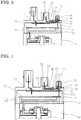
- FIG. 1 and FIG. 2 are a sectional configuration diagram and an A-A sectional view showing a motor drive device having a vehicle electronic control device according to embodiment 1 of the present invention.
- the motor drive device 100 is composed of an electric motor 51 and a vehicle electronic control device 10 which is integrally attached to an end in the axial direction of the electric motor 51 and which performs power feeding to the electric motor 51 and drive control for the electric motor 51.
- the electric motor 51 is a three-phase brushless motor, and includes: a rotor 52; a stator 54 having armature windings 53 for U phase, V phase, and W phase; a motor frame 55 covering the outer circumference of the stator 54; an output-side bearing 56 coaxially fixed to the motor frame 55 and rotatably supporting the rotor 52; an anti-output side bearing 57; and an output shaft 58.
- the vehicle electronic control device 10 includes: a control board 11; a power portion 12 for driving the electric motor 51; a frame 13 in which a plurality of electrically conductive plates are insert-molded; a signal connector 14 to which a torque sensor and a vehicle signal are connected; a power supply connector 40 connected to a power supply portion; a case 15 integrated with the signal connector 14 and the power supply connector 40 and surrounding the control board 11; a metallic heatsink 16 having contact with the power portion 12 and having a high thermal conductivity; and a case frame 17 to which a coil of a noise filter is mounted and in which a plurality of electrically conductive plates are insert-molded.
- the signal connector 14 formed on the case 15 is formed by: a housing portion 19 which forms a part of the case 15, is made of a resin member, and surrounds the control board 11; and a terminal portion 20 made of a metal conductor and formed integrally with the housing portion 19.
- the terminal portion 20 has: a terminal 20a for external connection, protruding from the housing portion 19; and an intermediate path portion 21 extending from the terminal 20a and connected to the control board 11.
- an exposure portion 23 is formed which allows the intermediate path portion 21 to be exposed over the entire periphery thereof.
- An upper surface 17a of the case frame 17 and an inner surface 19a of the housing portion 19 are fixed in close contact with each other.
- a groove portion 24 with a bottom is formed by the exposure portion 23 and the upper surface 17a of the case frame.
- the groove portion 24 is filled with an interface sealing member 25 for sealing the housing portion 19 and the intermediate path portion 21 in a liquid-tight manner.
- the intermediate path portion 21 of the terminal portion 20 extends to the position of the end of a terminal 18 extending from the frame 13 toward the seat face portion 22 side of the signal connector 14, and is joined at a joining portion 27 outside the housing portion 19.
- the intermediate path portion 21 is connected to the control board 11 via the terminal 18.
- a depressed portion 26 is formed in the outer surface of the housing portion 19, around the joining portion 27.
- the joining portion 27 is covered with a cover 28 fitted to the depressed portion 26.
- the depressed portion 26 is filled with an interface sealing member 29, whereby the cover 28 is sealed and fixed with the depressed portion 26 in a liquid-tight manner.
- the power supply connector 40 is composed of a housing portion 41 and a terminal portion 42.
- the terminal portion 42 has an intermediate path portion 43 embedded in the housing portion 41, and a seat face portion 44 on a fitting portion bottom surface.
- a bottomed storage portion 45 having a depressed shape is provided on the inner surface 19a side of the housing portion 41.
- the intermediate path portion 43 is exposed over the entire periphery thereof at the position of the bottomed storage portion 45.
- the bottomed storage portion 45 is filled with an interface sealing member 46 for sealing the exposed part of the intermediate path portion 43 and the housing portion 41 in a liquid-tight manner.
- an ignition switch (not shown) of the vehicle is turned on to supply power from the power supply portion to the control board 11 via the power supply connector 40, information signals from the torque sensor and a vehicle speed sensor are inputted via the signal connector 14 to a microcomputer (not shown) mounted on the control board 11, to calculate a current value corresponding to steering assist torque, the power portion 12 causes motor drive current to flow to the electric motor 51, thereby outputting a desired amount of assist torque in a desired rotational direction to the electric motor 51, and then power is transmitted from the output shaft 58 to a gear speed reducer 59.
- the control board 11 having an electronic component mounted thereon is housed inside the case 15, and the connector portion 20 for connecting the control board 11 to the outside is formed integrally with the case 15.
- the connector portion 20 is formed by the housing portion 19 covering the control board 11, and the terminal portion 20 integrally embedded in the housing portion 19.
- the terminal portion 20 has; the terminal 20a for external connection, protruding from the housing portion 19; and the intermediate path portion 21 extending from the terminal 20a and connected to the control board 11.
- the exposure portion 23 is formed which allows the intermediate path portion 21 to be exposed over the entire periphery thereof.
- the interface sealing member 25 for sealing the interface between the housing portion 19 and the intermediate path portion 21 is provided in the exposure portion 23.
- the intermediate path portion 21 of the terminal portion 20 extends to the position of the end of the terminal 18 extending from the frame 13 toward the seat face portion 22 side of the signal connector 14, and is joined with the joining portion 27 outside the housing portion 19, whereby the intermediate path portion 21 is connected to the control board 11 via the terminal 18.
- the depressed portion 26 is formed in the outer surface of the housing portion 19, around the joining portion 27.
- the joining portion 27 is covered with the cover 28 fitted to the depressed portion 26, the depressed portion 26 is filled with the interface sealing member 29, and the cover 28 is sealed and fixed with the depressed portion 26 in a liquid-tight manner.
- the bottomed storage portion 45 having a depressed shape is provided on the inner surface 19a side of the housing portion 41, the intermediate path portion 43 is exposed over the entire periphery thereof at the position of the bottomed storage portion 45, and the bottomed storage portion 45 is filled with the interface sealing member 46 for sealing the exposed portion of the intermediate path portion 43 and the housing portion 41 in a liquid-tight manner. Therefore, also in the power supply connector 40, water does not intrude to the control board 11.
- FIG. 3 is a partial sectional configuration diagram showing a vehicle electronic control device according to embodiment 2 of the present invention.
- the upper surface 17a of the case frame 17 and the inner surface 19a of the housing portion 19 are fixed in close contact with each other, and the groove portion 24 with a bottom is formed by the exposure portion 23 and the upper surface 17a of the case frame 17.
- a plate 31 is attached at the upper surface 17a of the case frame 17, thereby forming the groove portion 24 with a bottom.
- an adhesive tape may be used as the plate 31 as the plate 31, an adhesive tape may be used.
- FIG. 4 is a partial sectional configuration diagram showing a vehicle electronic control device according to embodiment 3 of the present invention.
- the intermediate path portion 21 of the terminal portion 20 is a single component made of a metallic conductor.
- a pre-mold type is used as the terminal portion 20 .
- the intermediate path portion 21 at a part other than the exposure portion 23 is partially covered with a pre-mold resin 30 formed separately from the housing portion 19, and an end 30a on the exposure portion 23 side of the pre-mold resin 30 is positioned away from the exposure portion 23 toward the seat face portion 22 side.
- Such a configuration allows the same effect as in the embodiments 1 and 2 to be obtained even in the case of using the terminal portion 20 of a pre-mold type.
- FIG. 5 shows a configuration diagram showing a vehicle electronic control device according to embodiment 4 of the present invention.
- the end 30a on the exposure portion 23 side of the pre-mold resin 30 of the terminal portion 20 is provided away from the exposure portion 23 toward the seat face portion 22 side, the end 30a of the pre-mold resin 30 is exposed to the exposure portion 23 side and forms a part of the groove portion 24.
- Such a configuration can provide the same effect as in embodiments 1 to 3, and in addition, allows use of the same molding component for positioning of the end 30a of the pre-mold resin 30 and for forming the exposure portion 23, whereby the signal connector 14 can be accurately molded and the quality can be improved.
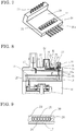
- FIG. 6 and FIG. 7 are a partial sectional configuration diagram showing a vehicle electronic control device according to embodiment 5 of the present invention, and a perspective view of the terminal portion 20 of a pre-mold type molded with pre-mold resin.
- the exposure portion 23 is provided, on the intermediate path portion 21 of the terminal portion 20, in a part of the housing portion 19, and the intermediate path portion 21 is exposed over the entire periphery thereof at the exposure portion 23.
- an exposure hole 32 which allows the intermediate path portion 21 to be exposed over the entire periphery thereof is formed in an intermediate part of the pre-mold resin 30, and is placed, and the inside of the exposure hole 32 is filled with an interface sealing member 33, whereby the intermediate path portion 21 exposed over the entire periphery thereof at the exposure hole 32, and the pre-mold resin are sealed.
- the end 30a of the pre-mold resin 30 is exposed at the exposure portion 23 and forms a part of the groove portion 24, the intermediate path portion 21 protruding from the pre-mold resin 30 and positioned at the exposure portion 23 is covered with the resin of the housing portion 19, and the interface sealing member 25 is provided at the interfaces among three parts of the intermediate path portion 21, the pre-mold resin 30, and the housing portion.
- Such a configuration can provide the same effect as in the above embodiments 1 to 4, and allows the exposure hole 32 to be also used as a hole for cutting a tie-bar portion 34 for arranging the terminal portion 20 in parallel with the resin plane to perform insert molding, whereby the cost for processing the pre-mold can be reduced.
- the exposure hole 32 can be used as a pressing position for the mold, and it is not necessary to form a terminal relief portion for mold clamping in the mold for allowing the intermediate path portion 21 to be exposed over the entire periphery thereof at the exposure portion 23, whereby the mold cost can be reduced.
- sealing for the exposure portion 23 two interfaces of the housing portion 19 and the pre-mold resin 30 are sealed with the interface sealing member 25. Therefore, the sealing interfaces are decreased, whereby sealing performance is improved.
- FIG. 8 and FIG. 9 are a partial sectional configuration diagram and a B-B sectional view showing a vehicle electronic control device according to embodiment 6 of the present invention.
- the end 30a of the pre-mold resin 30 is exposed at the exposure portion 23, and the terminal portion 20 positioned at the exposure portion 23 is covered with the resin of the housing portion 19.
- the exposure portion 23 is formed, on the outer periphery of the pre-mold resin 30, at a position other than the exposure hole 32.
- the pre-mold resin 30 is exposed over the entire periphery thereof, and the exposure portion 23 is filled with the interface sealing member 25 in a liquid-tight manner.
- FIG. 10 is a partial sectional configuration diagram showing a vehicle electronic control device according to embodiment 7 of the present invention.
- the groove portion 24 is formed, on the outer surface side of the housing portion 19, at a position different from the depressed portion 26 around the joining portion 27.
- the groove portion 24 is formed as a part of the depressed portion 26.
- Such a configuration can provide the same effect as in embodiments 1 to 6, and also allows the interface sealing member 29 in the depressed portion 26 to be shared with the groove portion 24, whereby the used materials can be decreased, the process time can be shortened, and the cost can be reduced.
- FIG. 11 is a partial sectional configuration diagram showing a vehicle electronic control device according to embodiment 8 of the present invention.
- the intermediate path portion 21 of the terminal portion 20 extends to the position of the end of the terminal 18 extending from the frame 13 toward the seat face portion 22 side of the signal connector 14, and is joined at the joining portion 27 outside the housing portion 19.
- the intermediate path portion 21 extends toward the control board 11 side and is directly connected to the control board 11.
- the exposure portion 23 may be used as a hole or groove for pressing at the time of mold clamping of the terminal portion 20 and the pre-mold resin 30 when the case 15 is molded.
- At least one of the interface sealing members 25 and 29 may be potting resin.
Landscapes
- Engineering & Computer Science (AREA)
- Power Engineering (AREA)
- Microelectronics & Electronic Packaging (AREA)
- Mechanical Engineering (AREA)
- Connector Housings Or Holding Contact Members (AREA)
- Motor Or Generator Frames (AREA)
- Casings For Electric Apparatus (AREA)
Abstract
Description
- The present invention relates to a vehicle electronic control device and a motor drive device, and in particular, to a waterproof structure around a connector for transferring power, a signal, and the like for these devices.
- Some of conventional waterproof structures around a connector of a vehicle electronic control device use a waterproof connector to address waterproofness.
- However, even in the case of using a waterproof connector, it is necessary to also consider that a very small gap arises between a housing and a terminal provided in the housing, and then, due to temperature change by heat generation and cooling of an electronic device, water drop is absorbed.
- In particular, if water drop enters the electronic control device, short-circuit occurs because of small-sized components. As a result, the electronic control device does not function, and further, travelling of the vehicle might be influenced. Accordingly, reliably ensuring waterproofness is an important matter.
- Therefore, for example, as in an electronic control device disclosed in
Patent Document 1, a storage portion in which a sealing agent can be stored is formed on the inner wall side of a penetration wall through which a terminal penetrates, and the sealing agent is applied from the inside of a housing in which the electronic control device is provided. - Patent Document 1: Japanese Patent No.
4929659 - In the conventional structure disclosed in
Patent Document 1, since the sealing agent is applied from the inside of the housing in which the electronic control device is provided, it is necessary to provide the storage portion protruding on the inner surface side of the penetration wall through which the terminal penetrates. - Currently, the electronic control device body is downsized, and also the housing itself is increasingly reduced. Depending on the position at which the storage portion is provided and the size of the storage portion, size reduction and cost reduction of the device are influenced.
- In waterproof perspective, water might intrude unless the interface between the terminal and the entire peripheral surface around the terminal is sealed, and further, the interface between resin members composing the housing is also a target for a waterproof structure. Therefore, it is necessary to seal all these parts.
- The present invention has been made to solve the above problem, and an object of the present invention is to provide a vehicle electronic control device and a motor drive device that enable further simplification of the waterproof structure around a connector and enable cost reduction and size reduction.
- A vehicle electronic control device according to the present invention is a vehicle electronic control device in which a control board having an electronic component mounted thereon is housed inside a case and a connector portion for connecting the control board to outside is formed integrally with the case. The connector portion is formed by a housing portion covering the control board, and a terminal portion integrally embedded in the housing portion. The terminal portion has: a terminal for external connection, protruding from the housing portion; and an intermediate path portion extending from the terminal and connected to the control board. An exposure portion which allows the intermediate path portion to be exposed over an entire periphery thereof is formed in a part of the housing portion. An interface sealing member for sealing an interface between the housing portion and the intermediate path portion is provided in the exposure portion.
- The present invention can achieve a vehicle electronic control device and a motor drive device that have an enhanced waterproof function around a connector and have a further simplified waterproof structure, thereby achieving cost reduction and size reduction.
-
- [
FIG. 1] FIG. 1 is a sectional configuration diagram showing a motor drive device having a vehicle electronic control device according toembodiment 1 of the present invention. - [
FIG. 2] FIG. 2 is an A-A sectional view inFIG. 1 . - [
FIG. 3] FIG. 3 is a partial sectional configuration diagram showing a motor drive device having a vehicle electronic control device according to embodiment 2 of the present invention. - [
FIG. 4] FIG. 4 is a partial sectional configuration diagram showing a motor drive device having a vehicle electronic control device according to embodiment 3 of the present invention. - [
FIG. 5] FIG. 5 is a partial sectional configuration diagram showing a motor drive device having a vehicle electronic control device according to embodiment 4 of the present invention. - [
FIG. 6] FIG. 6 is a partial sectional configuration diagram showing a motor drive device having a vehicle electronic control device according to embodiment 5 of the present invention. - [
FIG. 7] FIG. 7 is a perspective view showing a terminal portion of a pre-mold type according to embodiment 5 in the present invention. - [
FIG. 8] FIG. 8 is a partial sectional configuration diagram showing a motor drive device having a vehicle electronic control device according to embodiment 6 of the present invention. - [
FIG. 9] FIG. 9 is a B-B sectional view inFIG. 8 . - [
FIG. 10] FIG. 10 is a partial sectional configuration diagram showing a motor drive device having a vehicle electronic control device according to embodiment 7 of the present invention. - [
FIG. 11] FIG. 11 is a partial sectional configuration diagram showing a motor drive device having a vehicle electronic control device according to embodiment 8 of the present invention. - Hereinafter,
embodiment 1 of the present invention will be described with reference to the drawings.FIG. 1 and FIG. 2 are a sectional configuration diagram and an A-A sectional view showing a motor drive device having a vehicle electronic control device according toembodiment 1 of the present invention. - In
FIG. 1 and FIG. 2 , themotor drive device 100 is composed of anelectric motor 51 and a vehicleelectronic control device 10 which is integrally attached to an end in the axial direction of theelectric motor 51 and which performs power feeding to theelectric motor 51 and drive control for theelectric motor 51. - The
electric motor 51 is a three-phase brushless motor, and includes: arotor 52; astator 54 havingarmature windings 53 for U phase, V phase, and W phase; amotor frame 55 covering the outer circumference of thestator 54; an output-side bearing 56 coaxially fixed to themotor frame 55 and rotatably supporting therotor 52; an anti-output side bearing 57; and anoutput shaft 58. - The vehicle
electronic control device 10 includes: acontrol board 11; apower portion 12 for driving theelectric motor 51; aframe 13 in which a plurality of electrically conductive plates are insert-molded; asignal connector 14 to which a torque sensor and a vehicle signal are connected; apower supply connector 40 connected to a power supply portion; acase 15 integrated with thesignal connector 14 and thepower supply connector 40 and surrounding thecontrol board 11; ametallic heatsink 16 having contact with thepower portion 12 and having a high thermal conductivity; and acase frame 17 to which a coil of a noise filter is mounted and in which a plurality of electrically conductive plates are insert-molded. - The
signal connector 14 formed on thecase 15 is formed by: ahousing portion 19 which forms a part of thecase 15, is made of a resin member, and surrounds thecontrol board 11; and aterminal portion 20 made of a metal conductor and formed integrally with thehousing portion 19. - The
terminal portion 20 has: aterminal 20a for external connection, protruding from thehousing portion 19; and anintermediate path portion 21 extending from theterminal 20a and connected to thecontrol board 11. In a part of thehousing portion 19, anexposure portion 23 is formed which allows theintermediate path portion 21 to be exposed over the entire periphery thereof. - An upper surface 17a of the
case frame 17 and an inner surface 19a of thehousing portion 19 are fixed in close contact with each other. Agroove portion 24 with a bottom is formed by theexposure portion 23 and the upper surface 17a of the case frame. Thegroove portion 24 is filled with aninterface sealing member 25 for sealing thehousing portion 19 and theintermediate path portion 21 in a liquid-tight manner. - The
intermediate path portion 21 of theterminal portion 20 extends to the position of the end of aterminal 18 extending from theframe 13 toward theseat face portion 22 side of thesignal connector 14, and is joined at a joiningportion 27 outside thehousing portion 19. Thus, theintermediate path portion 21 is connected to thecontrol board 11 via theterminal 18. - Further, a
depressed portion 26 is formed in the outer surface of thehousing portion 19, around the joiningportion 27. The joiningportion 27 is covered with acover 28 fitted to thedepressed portion 26. Thedepressed portion 26 is filled with aninterface sealing member 29, whereby thecover 28 is sealed and fixed with thedepressed portion 26 in a liquid-tight manner. - The
power supply connector 40 is composed of ahousing portion 41 and aterminal portion 42. Theterminal portion 42 has anintermediate path portion 43 embedded in thehousing portion 41, and aseat face portion 44 on a fitting portion bottom surface. On theintermediate path portion 43, a bottomedstorage portion 45 having a depressed shape is provided on the inner surface 19a side of thehousing portion 41. Theintermediate path portion 43 is exposed over the entire periphery thereof at the position of the bottomedstorage portion 45. The bottomedstorage portion 45 is filled with aninterface sealing member 46 for sealing the exposed part of theintermediate path portion 43 and thehousing portion 41 in a liquid-tight manner. - In the vehicle
electronic control device 10 configured as described above, an ignition switch (not shown) of the vehicle is turned on to supply power from the power supply portion to thecontrol board 11 via thepower supply connector 40, information signals from the torque sensor and a vehicle speed sensor are inputted via thesignal connector 14 to a microcomputer (not shown) mounted on thecontrol board 11, to calculate a current value corresponding to steering assist torque, thepower portion 12 causes motor drive current to flow to theelectric motor 51, thereby outputting a desired amount of assist torque in a desired rotational direction to theelectric motor 51, and then power is transmitted from theoutput shaft 58 to agear speed reducer 59. - As described above, in the
present embodiment 1, in the vehicleelectronic control device 10, thecontrol board 11 having an electronic component mounted thereon is housed inside thecase 15, and theconnector portion 20 for connecting thecontrol board 11 to the outside is formed integrally with thecase 15. Theconnector portion 20 is formed by thehousing portion 19 covering thecontrol board 11, and theterminal portion 20 integrally embedded in thehousing portion 19. Theterminal portion 20 has; theterminal 20a for external connection, protruding from thehousing portion 19; and theintermediate path portion 21 extending from theterminal 20a and connected to thecontrol board 11. In a part of thehousing portion 19, theexposure portion 23 is formed which allows theintermediate path portion 21 to be exposed over the entire periphery thereof. Theinterface sealing member 25 for sealing the interface between thehousing portion 19 and theintermediate path portion 21 is provided in theexposure portion 23. Thus, at least for thesignal connector 14, a storage portion for storing an interface sealing member need not be provided so as to protrude on the inner surface 19a side of thehousing portion 19, and size reduction and cost reduction of the device can be achieved. - In addition, the
intermediate path portion 21 of theterminal portion 20 extends to the position of the end of the terminal 18 extending from theframe 13 toward theseat face portion 22 side of thesignal connector 14, and is joined with the joiningportion 27 outside thehousing portion 19, whereby theintermediate path portion 21 is connected to thecontrol board 11 via theterminal 18. Further, thedepressed portion 26 is formed in the outer surface of thehousing portion 19, around the joiningportion 27. The joiningportion 27 is covered with thecover 28 fitted to thedepressed portion 26, thedepressed portion 26 is filled with theinterface sealing member 29, and thecover 28 is sealed and fixed with thedepressed portion 26 in a liquid-tight manner. Therefore, even if the exterior side of thecase 15 is wetted and water drop is accumulated on theseat face portion 22 of thesignal connector 14, and then if water enters the interface between theintermediate path portion 21 and thehousing portion 19, the water is prevented from intruding to thecontrol board 11 because the entire periphery around the joiningportion 27 is filled with theinterface sealing member 29. - In addition, for the
power supply connector 40, the bottomedstorage portion 45 having a depressed shape is provided on the inner surface 19a side of thehousing portion 41, theintermediate path portion 43 is exposed over the entire periphery thereof at the position of the bottomedstorage portion 45, and the bottomedstorage portion 45 is filled with theinterface sealing member 46 for sealing the exposed portion of theintermediate path portion 43 and thehousing portion 41 in a liquid-tight manner. Therefore, also in thepower supply connector 40, water does not intrude to thecontrol board 11. -
FIG. 3 is a partial sectional configuration diagram showing a vehicle electronic control device according to embodiment 2 of the present invention. - In
embodiment 1, as for thegroove portion 24, the upper surface 17a of thecase frame 17 and the inner surface 19a of thehousing portion 19 are fixed in close contact with each other, and thegroove portion 24 with a bottom is formed by theexposure portion 23 and the upper surface 17a of thecase frame 17. On the other hand, in the present embodiment 2, instead of thecase frame 17, aplate 31 is attached at the upper surface 17a of thecase frame 17, thereby forming thegroove portion 24 with a bottom. - As the
plate 31, an adhesive tape may be used. - Even such a configuration can provide the same effect as in
embodiment 1. -
FIG. 4 is a partial sectional configuration diagram showing a vehicle electronic control device according to embodiment 3 of the present invention. - In the
above embodiments 1 and 2, theintermediate path portion 21 of theterminal portion 20 is a single component made of a metallic conductor. On the other hand, in the present embodiment 3, as theterminal portion 20, a pre-mold type is used. Theintermediate path portion 21 at a part other than theexposure portion 23 is partially covered with apre-mold resin 30 formed separately from thehousing portion 19, and anend 30a on theexposure portion 23 side of thepre-mold resin 30 is positioned away from theexposure portion 23 toward theseat face portion 22 side. - Such a configuration allows the same effect as in the
embodiments 1 and 2 to be obtained even in the case of using theterminal portion 20 of a pre-mold type. -
FIG. 5 shows a configuration diagram showing a vehicle electronic control device according to embodiment 4 of the present invention. - As shown in
FIG. 5 , although in the above embodiment 3, theend 30a on theexposure portion 23 side of thepre-mold resin 30 of theterminal portion 20 is provided away from theexposure portion 23 toward theseat face portion 22 side, theend 30a of thepre-mold resin 30 is exposed to theexposure portion 23 side and forms a part of thegroove portion 24. - Such a configuration can provide the same effect as in
embodiments 1 to 3, and in addition, allows use of the same molding component for positioning of theend 30a of thepre-mold resin 30 and for forming theexposure portion 23, whereby thesignal connector 14 can be accurately molded and the quality can be improved. -
FIG. 6 andFIG. 7 are a partial sectional configuration diagram showing a vehicle electronic control device according to embodiment 5 of the present invention, and a perspective view of theterminal portion 20 of a pre-mold type molded with pre-mold resin. - In embodiment 4, the
exposure portion 23 is provided, on theintermediate path portion 21 of theterminal portion 20, in a part of thehousing portion 19, and theintermediate path portion 21 is exposed over the entire periphery thereof at theexposure portion 23. On the other hand, in the present embodiment 5, as shown inFIG. 6 andFIG. 7 , anexposure hole 32 which allows theintermediate path portion 21 to be exposed over the entire periphery thereof is formed in an intermediate part of thepre-mold resin 30, and is placed, and the inside of theexposure hole 32 is filled with an interface sealing member 33, whereby theintermediate path portion 21 exposed over the entire periphery thereof at theexposure hole 32, and the pre-mold resin are sealed. - In addition, the
end 30a of thepre-mold resin 30 is exposed at theexposure portion 23 and forms a part of thegroove portion 24, theintermediate path portion 21 protruding from thepre-mold resin 30 and positioned at theexposure portion 23 is covered with the resin of thehousing portion 19, and theinterface sealing member 25 is provided at the interfaces among three parts of theintermediate path portion 21, thepre-mold resin 30, and the housing portion. - Such a configuration can provide the same effect as in the
above embodiments 1 to 4, and allows theexposure hole 32 to be also used as a hole for cutting a tie-bar portion 34 for arranging theterminal portion 20 in parallel with the resin plane to perform insert molding, whereby the cost for processing the pre-mold can be reduced. - In addition, when the terminal portion and the housing portion are integrally molded, the
exposure hole 32 can be used as a pressing position for the mold, and it is not necessary to form a terminal relief portion for mold clamping in the mold for allowing theintermediate path portion 21 to be exposed over the entire periphery thereof at theexposure portion 23, whereby the mold cost can be reduced. - Further, by the sealing for the
exposure portion 23, two interfaces of thehousing portion 19 and thepre-mold resin 30 are sealed with theinterface sealing member 25. Therefore, the sealing interfaces are decreased, whereby sealing performance is improved. -
FIG. 8 and FIG. 9 are a partial sectional configuration diagram and a B-B sectional view showing a vehicle electronic control device according to embodiment 6 of the present invention. - In the above embodiment 5, the
end 30a of thepre-mold resin 30 is exposed at theexposure portion 23, and theterminal portion 20 positioned at theexposure portion 23 is covered with the resin of thehousing portion 19. On the other hand, in the present embodiment 6, as shown inFIG. 8 and FIG. 9 , theexposure portion 23 is formed, on the outer periphery of thepre-mold resin 30, at a position other than theexposure hole 32. At theexposure portion 23, thepre-mold resin 30 is exposed over the entire periphery thereof, and theexposure portion 23 is filled with theinterface sealing member 25 in a liquid-tight manner. - Even such a configuration can provide the same effect as in embodiment 5.
-
FIG. 10 is a partial sectional configuration diagram showing a vehicle electronic control device according to embodiment 7 of the present invention. - In the
above embodiments 1 to 6, thegroove portion 24 is formed, on the outer surface side of thehousing portion 19, at a position different from thedepressed portion 26 around the joiningportion 27. On the other hand, in the present embodiment 7, as shown inFIG. 10 , thegroove portion 24 is formed as a part of thedepressed portion 26. - Such a configuration can provide the same effect as in
embodiments 1 to 6, and also allows theinterface sealing member 29 in thedepressed portion 26 to be shared with thegroove portion 24, whereby the used materials can be decreased, the process time can be shortened, and the cost can be reduced. -
FIG. 11 is a partial sectional configuration diagram showing a vehicle electronic control device according to embodiment 8 of the present invention. - In the
above embodiments 1 to 7, theintermediate path portion 21 of theterminal portion 20 extends to the position of the end of the terminal 18 extending from theframe 13 toward theseat face portion 22 side of thesignal connector 14, and is joined at the joiningportion 27 outside thehousing portion 19. On the other hand, in the present embodiment 7, as shown inFIG. 11 , theintermediate path portion 21 extends toward thecontrol board 11 side and is directly connected to thecontrol board 11. - In such a configuration, since the joining
portion 27 does not extend to the outside of thehousing portion 19 as in theabove embodiments 1 to 7, it is not necessary to provide thecover 28, thedepressed portion 26, and theinterface sealing member 29 for ensuring waterproofness. Thus, the number of components and the number of process steps can be decreased, whereby size reduction and cost reduction can be achieved. - In
embodiments 1 to 8, theexposure portion 23 may be used as a hole or groove for pressing at the time of mold clamping of theterminal portion 20 and thepre-mold resin 30 when thecase 15 is molded. - At least one of the
interface sealing members - It is noted that, within the scope of the present invention, the above embodiments may be freely combined with each other, or each of the above embodiments may be modified or simplified as appropriate.
-
- 10
- vehicle electronic control device
- 11
- control board
- 12
- power portion
- 13
- frame
- 14
- signal connector
- 15
- case
- 16
- heatsink
- 17
- case frame
- 17a
- upper surface
- 18
- terminal
- 19
- housing portion
- 19a
- inner surface
- 20
- terminal portion
- 20a
- terminal
- 21
- intermediate path portion
- 22
- seat face portion
- 23
- exposure portion
- 24
- groove portion
- 25
- interface sealing member
- 26
- depressed portion
- 27
- joining portion
- 28
- cover
- 29
- interface sealing member
- 30
- pre-mold resin
- 30a
- end
- 31
- plate
- 32
- exposure hole
- 33
- interface sealing member
- 34
- tie-bar portion
- 40
- power supply connector
- 41
- housing portion
- 42
- terminal portion
- 43
- intermediate path portion
- 44
- seat face portion
- 45
- bottomed storage portion
- 46
- interface sealing member
- 51
- electric motor
- 52
- rotor
- 53
- armature winding
- 54
- stator
- 55
- motor frame
- 56, 57
- bearing
- 58
- output shaft
- 59
- gear speed reducer
- 100
- motor drive device
Claims (14)
- A vehicle electronic control device in which a control board having an electronic component mounted thereon is housed inside a case and a connector portion for connecting the control board to outside is formed integrally with the case, wherein
the connector portion is formed by a housing portion covering the control board, and a terminal portion integrally embedded in the housing portion,
the terminal portion has: a terminal for external connection, protruding from the housing portion; and an intermediate path portion extending from the terminal and connected to the control board,
an exposure portion which allows the intermediate path portion to be exposed over an entire periphery thereof is formed in a part of the housing portion, and
an interface sealing member for sealing an interface between the housing portion and the intermediate path portion is provided in the exposure portion. - The vehicle electronic control device according to claim 1, wherein
a plate having contact with the housing portion and forming a groove portion with a bottom is provided on the control board side of the housing portion, at a position corresponding to the exposure portion, and
the interface sealing member is provided in the groove portion. - The vehicle electronic control device according to claim 2, wherein
an adhesive tape is used as the plate. - The vehicle electronic control device according to claim 2 or 3, wherein
the intermediate path portion of the terminal portion, at a part other than the exposure portion, is covered with pre-mold resin formed by resin separate from the housing portion. - The vehicle electronic control device according to claim 4, wherein
an end of the pre-mold resin is exposed on the exposure portion side and forms a part of the groove portion. - The vehicle electronic control device according to claim 4 or 5, wherein
an exposure hole which allows the intermediate path portion to be exposed over an entire periphery thereof is formed in a part of the pre-mold resin, and
an interface sealing member is provided in the exposure hole. - The vehicle electronic control device according to claim 6, wherein
the exposure hole is used as a pressing position for a mold for integrally molding the terminal portion and the housing portion. - The vehicle electronic control device according to claim 6 or 7, wherein
an end of the pre-mold resin protrudes on the exposure portion side and forms a part of the groove portion, and
the interface sealing member is provided at interfaces among three parts of the intermediate path portion, the pre-mold resin, and the housing portion. - The vehicle electronic control device according to any one of claims 6 to 8, wherein
the exposure portion is formed, on an outer periphery of the pre-mold resin, at a position other than the exposure hole, and
the pre-mold resin is exposed over an entire periphery thereof at the exposure portion. - The vehicle electronic control device according to any one of claims 1 to 9, wherein
the housing portion has a seat face portion, and
the terminal portion is formed such that the terminal is inserted substantially perpendicularly into the seat face portion and the intermediate path portion is bent to extend in a direction different from that of the terminal, and then extends out from the seat face portion side again. - The vehicle electronic control device according to any one of claims 1 to 10, wherein
a terminal group extending from the control board is joined with the terminal, a position of the joining being at an exterior of the housing portion,
a depressed portion is provided around the position of the joining, and the exposure portion is provided near the depressed portion,
a cover which covers the position of the joining is fitted to the depressed portion, and
an interface sealing member is provided in the depressed portion and the exposure portion. - The vehicle electronic control device according to any one of claims 1 to 9, wherein
the housing portion has a seat face portion, and
the terminal portion is formed such that the terminal is inserted substantially perpendicularly into the seat face portion and the intermediate path portion is bent to extend in a direction different from that of the terminal, and then extends out toward the control board side, to be connected to the control board. - The vehicle electronic control device according to any one of claims 1 to 12, wherein
the interface sealing member is potting resin. - A motor drive device comprising:an electric motor; andthe vehicle electronic control device according to any one of claims 1 to 13, integrally attached to an end in an axial direction of the electric motor.
Applications Claiming Priority (1)
| Application Number | Priority Date | Filing Date | Title |
|---|---|---|---|
| PCT/JP2014/075181 WO2016046898A1 (en) | 2014-09-24 | 2014-09-24 | Vehicular electronic control device and motor drive device |
Publications (3)
| Publication Number | Publication Date |
|---|---|
| EP3200286A1 true EP3200286A1 (en) | 2017-08-02 |
| EP3200286A4 EP3200286A4 (en) | 2018-05-23 |
| EP3200286B1 EP3200286B1 (en) | 2021-08-04 |
Family
ID=55580462
Family Applications (1)
| Application Number | Title | Priority Date | Filing Date |
|---|---|---|---|
| EP14902408.5A Active EP3200286B1 (en) | 2014-09-24 | 2014-09-24 | Vehicular electronic control device and motor drive device |
Country Status (5)
| Country | Link |
|---|---|
| US (1) | US10734868B2 (en) |
| EP (1) | EP3200286B1 (en) |
| JP (1) | JP6218955B2 (en) |
| CN (1) | CN106605336B (en) |
| WO (1) | WO2016046898A1 (en) |
Cited By (2)
| Publication number | Priority date | Publication date | Assignee | Title |
|---|---|---|---|---|
| EP3312975A1 (en) * | 2016-10-06 | 2018-04-25 | Superwinch, LLC | Motor control modules with multiple potted sub-modules, and associated systems and methods |
| US11606000B2 (en) | 2017-10-27 | 2023-03-14 | Hitachi Astemo, Ltd. | Electric drive device and electric power steering device |
Families Citing this family (12)
| Publication number | Priority date | Publication date | Assignee | Title |
|---|---|---|---|---|
| JP6443055B2 (en) * | 2015-01-08 | 2018-12-26 | 株式会社デンソー | Drive device and drive device manufacturing method |
| US10256580B2 (en) | 2016-10-03 | 2019-04-09 | Superwinch, Llc | Power connectors with integrated fuse supports, and associated systems and methods |
| US10781086B2 (en) | 2016-10-31 | 2020-09-22 | Westin Automotive Products, Inc. | Winches with dual mode remote control, and associated systems and methods |
| US11140705B2 (en) * | 2017-07-14 | 2021-10-05 | Apple Inc. | Configuration of grant-less uplink transmissions for a user equipment |
| JP6966259B2 (en) * | 2017-08-25 | 2021-11-10 | 日立Astemo株式会社 | Resin-sealed in-vehicle electronic control device |
| WO2019077647A1 (en) * | 2017-10-16 | 2019-04-25 | 三菱電機株式会社 | Electric power steering apparatus |
| JP7124401B2 (en) * | 2018-04-10 | 2022-08-24 | 株式会社デンソー | drive |
| EP3739733B1 (en) * | 2019-05-13 | 2022-08-31 | SPAL Automotive S.r.l. | Electric machine |
| TWI710168B (en) * | 2020-01-21 | 2020-11-11 | 大陸商東莞立訊技術有限公司 | Connector |
| JP2023051602A (en) | 2021-09-30 | 2023-04-11 | 日本電産株式会社 | motor |
| US12323035B2 (en) * | 2021-09-30 | 2025-06-03 | Nidec Corporation | Motor |
| US20240429647A1 (en) * | 2023-06-26 | 2024-12-26 | Deere & Company | Electronic assembly with sealed electrical connector |
Family Cites Families (25)
| Publication number | Priority date | Publication date | Assignee | Title |
|---|---|---|---|---|
| JPH0419356Y2 (en) * | 1987-06-26 | 1992-04-30 | ||
| JP2522511Y2 (en) * | 1989-01-26 | 1997-01-16 | オムロン 株式会社 | Seal structure for electrical equipment |
| US6971237B2 (en) | 2000-11-08 | 2005-12-06 | Moog Inc. | Servoactuator having motor-driven actuator with hydraulic force amplification |
| US20020053205A1 (en) | 2000-11-08 | 2002-05-09 | Moog Inc. | Motor-driven actuator with hydraulic force amplification |
| JP2002231405A (en) * | 2001-01-31 | 2002-08-16 | Sumitomo Wiring Syst Ltd | Waterproof connector and injection state detecting method of potting material in waterproof connector using potting material |
| JP4220880B2 (en) * | 2003-10-17 | 2009-02-04 | 住友重機械工業株式会社 | Waterproof terminal block unit |
| US6966800B2 (en) * | 2004-03-22 | 2005-11-22 | Fci Americas Technology, Inc. | Overmolded electrical connector |
| JP2006287065A (en) * | 2005-04-01 | 2006-10-19 | Denso Corp | Electronic equipment |
| JP4929659B2 (en) | 2005-09-26 | 2012-05-09 | 株式会社ジェイテクト | Electronic control device |
| US7588444B2 (en) * | 2006-02-01 | 2009-09-15 | Nidec Corporation | Busbar unit, electric motor and electrohydraulic power steering system furnished with the busbar unit, and method of manufacturing the busbar unit |
| JP4402057B2 (en) * | 2006-02-21 | 2010-01-20 | 三菱電機株式会社 | Controller-integrated rotating electrical machine |
| DE112007003343B4 (en) | 2007-02-19 | 2021-03-25 | Mitsubishi Electric Corp. | Structure of a motor connection |
| KR101045417B1 (en) * | 2007-03-28 | 2011-06-30 | 미쓰비시덴키 가부시키가이샤 | Car alternator |
| JP5101974B2 (en) * | 2007-10-02 | 2012-12-19 | 日本圧着端子製造株式会社 | Metal component support and manufacturing method thereof |
| JP2009112063A (en) * | 2007-10-26 | 2009-05-21 | Nippon Densan Corp | Enclosure for housing electronic component |
| JP4591855B2 (en) * | 2008-05-14 | 2010-12-01 | Smk株式会社 | Socket for mounting electronic components |
| JP5028441B2 (en) * | 2009-03-24 | 2012-09-19 | 日立オートモティブシステムズ株式会社 | Electronic control device |
| JP5950258B2 (en) * | 2011-08-19 | 2016-07-13 | パナソニックIpマネジメント株式会社 | Electronics |
| JP5774207B2 (en) * | 2012-04-16 | 2015-09-09 | 三菱電機株式会社 | Rotating electric machine |
| WO2013157066A1 (en) * | 2012-04-16 | 2013-10-24 | 三菱電機株式会社 | Rotating electrical machine |
| JP6119631B2 (en) * | 2014-02-18 | 2017-04-26 | 株式会社デンソー | Rotating electric machine |
| EP3552661A1 (en) * | 2014-02-21 | 2019-10-16 | Cardiac Pacemakers, Inc. | Filtered feedthrough assembly for implantable medical electronic devices |
| JP6302093B2 (en) * | 2015-01-14 | 2018-03-28 | 日立オートモティブシステムズ株式会社 | Electronic control unit |
| JP6676144B2 (en) * | 2016-03-14 | 2020-04-08 | 三菱電機株式会社 | Electric power steering device |
| JP6492127B2 (en) * | 2016-08-11 | 2019-03-27 | ハンオン システムズ | Inverter-integrated BLDC motor |
-
2014
- 2014-09-24 JP JP2016549690A patent/JP6218955B2/en not_active Expired - Fee Related
- 2014-09-24 EP EP14902408.5A patent/EP3200286B1/en active Active
- 2014-09-24 US US15/324,007 patent/US10734868B2/en not_active Expired - Fee Related
- 2014-09-24 WO PCT/JP2014/075181 patent/WO2016046898A1/en not_active Ceased
- 2014-09-24 CN CN201480081754.2A patent/CN106605336B/en not_active Expired - Fee Related
Cited By (2)
| Publication number | Priority date | Publication date | Assignee | Title |
|---|---|---|---|---|
| EP3312975A1 (en) * | 2016-10-06 | 2018-04-25 | Superwinch, LLC | Motor control modules with multiple potted sub-modules, and associated systems and methods |
| US11606000B2 (en) | 2017-10-27 | 2023-03-14 | Hitachi Astemo, Ltd. | Electric drive device and electric power steering device |
Also Published As
| Publication number | Publication date |
|---|---|
| CN106605336A (en) | 2017-04-26 |
| US10734868B2 (en) | 2020-08-04 |
| JPWO2016046898A1 (en) | 2017-04-27 |
| EP3200286B1 (en) | 2021-08-04 |
| CN106605336B (en) | 2019-05-10 |
| EP3200286A4 (en) | 2018-05-23 |
| US20170207685A1 (en) | 2017-07-20 |
| JP6218955B2 (en) | 2017-10-25 |
| WO2016046898A1 (en) | 2016-03-31 |
Similar Documents
| Publication | Publication Date | Title |
|---|---|---|
| EP3200286B1 (en) | Vehicular electronic control device and motor drive device | |
| US9473004B2 (en) | Drive device and electric power steering device including the drive device | |
| EP3334015B1 (en) | Inverter-integrated motor | |
| JP6443055B2 (en) | Drive device and drive device manufacturing method | |
| US8136623B2 (en) | Electric motor apparatus for electric power steering and electric power steering apparatus | |
| US9893586B2 (en) | Driver apparatus provided with a motor and a control unit | |
| JP5518255B2 (en) | Drive unit-integrated rotating electrical machine | |
| JP4479821B2 (en) | Control device-integrated electric power steering apparatus motor and electric power steering apparatus | |
| JP5927836B2 (en) | Drive device | |
| US20170305457A1 (en) | Control unit and electric power steering device employing control unit | |
| WO2017134959A1 (en) | Drive device | |
| WO2017141637A1 (en) | Drive device | |
| JP2009278852A (en) | Power feeding apparatus and brushless motor | |
| KR20250143226A (en) | Power pack of electronic power steering | |
| JP4456433B2 (en) | Manufacturing method of brush holder | |
| JP2013258818A (en) | Motor and method for manufacturing motor | |
| JP2009254128A (en) | motor | |
| WO2026042787A1 (en) | Electronic device | |
| WO2025018229A1 (en) | Drive device | |
| WO2026042790A1 (en) | Electronic device | |
| JP2007106284A (en) | Electric power steering device |
Legal Events
| Date | Code | Title | Description |
|---|---|---|---|
| STAA | Information on the status of an ep patent application or granted ep patent |
Free format text: STATUS: THE INTERNATIONAL PUBLICATION HAS BEEN MADE |
|
| PUAI | Public reference made under article 153(3) epc to a published international application that has entered the european phase |
Free format text: ORIGINAL CODE: 0009012 |
|
| STAA | Information on the status of an ep patent application or granted ep patent |
Free format text: STATUS: REQUEST FOR EXAMINATION WAS MADE |
|
| 17P | Request for examination filed |
Effective date: 20161123 |
|
| AK | Designated contracting states |
Kind code of ref document: A1 Designated state(s): AL AT BE BG CH CY CZ DE DK EE ES FI FR GB GR HR HU IE IS IT LI LT LU LV MC MK MT NL NO PL PT RO RS SE SI SK SM TR |
|
| AX | Request for extension of the european patent |
Extension state: BA ME |
|
| DAX | Request for extension of the european patent (deleted) | ||
| A4 | Supplementary search report drawn up and despatched |
Effective date: 20180424 |
|
| RIC1 | Information provided on ipc code assigned before grant |
Ipc: H01R 13/405 20060101ALI20180418BHEP Ipc: H02K 5/22 20060101ALI20180418BHEP Ipc: H01R 13/52 20060101AFI20180418BHEP |
|
| STAA | Information on the status of an ep patent application or granted ep patent |
Free format text: STATUS: EXAMINATION IS IN PROGRESS |
|
| 17Q | First examination report despatched |
Effective date: 20200207 |
|
| GRAP | Despatch of communication of intention to grant a patent |
Free format text: ORIGINAL CODE: EPIDOSNIGR1 |
|
| STAA | Information on the status of an ep patent application or granted ep patent |
Free format text: STATUS: GRANT OF PATENT IS INTENDED |
|
| INTG | Intention to grant announced |
Effective date: 20210415 |
|
| GRAS | Grant fee paid |
Free format text: ORIGINAL CODE: EPIDOSNIGR3 |
|
| GRAA | (expected) grant |
Free format text: ORIGINAL CODE: 0009210 |
|
| STAA | Information on the status of an ep patent application or granted ep patent |
Free format text: STATUS: THE PATENT HAS BEEN GRANTED |
|
| AK | Designated contracting states |
Kind code of ref document: B1 Designated state(s): AL AT BE BG CH CY CZ DE DK EE ES FI FR GB GR HR HU IE IS IT LI LT LU LV MC MK MT NL NO PL PT RO RS SE SI SK SM TR |
|
| REG | Reference to a national code |
Ref country code: GB Ref legal event code: FG4D |
|
| REG | Reference to a national code |
Ref country code: AT Ref legal event code: REF Ref document number: 1417966 Country of ref document: AT Kind code of ref document: T Effective date: 20210815 |
|
| REG | Reference to a national code |
Ref country code: CH Ref legal event code: EP |
|
| REG | Reference to a national code |
Ref country code: DE Ref legal event code: R096 Ref document number: 602014079292 Country of ref document: DE |
|
| REG | Reference to a national code |
Ref country code: IE Ref legal event code: FG4D |
|
| REG | Reference to a national code |
Ref country code: LT Ref legal event code: MG9D |
|
| REG | Reference to a national code |
Ref country code: NL Ref legal event code: MP Effective date: 20210804 |
|
| REG | Reference to a national code |
Ref country code: AT Ref legal event code: MK05 Ref document number: 1417966 Country of ref document: AT Kind code of ref document: T Effective date: 20210804 |
|
| PG25 | Lapsed in a contracting state [announced via postgrant information from national office to epo] |
Ref country code: HR Free format text: LAPSE BECAUSE OF FAILURE TO SUBMIT A TRANSLATION OF THE DESCRIPTION OR TO PAY THE FEE WITHIN THE PRESCRIBED TIME-LIMIT Effective date: 20210804 Ref country code: SE Free format text: LAPSE BECAUSE OF FAILURE TO SUBMIT A TRANSLATION OF THE DESCRIPTION OR TO PAY THE FEE WITHIN THE PRESCRIBED TIME-LIMIT Effective date: 20210804 Ref country code: RS Free format text: LAPSE BECAUSE OF FAILURE TO SUBMIT A TRANSLATION OF THE DESCRIPTION OR TO PAY THE FEE WITHIN THE PRESCRIBED TIME-LIMIT Effective date: 20210804 Ref country code: FI Free format text: LAPSE BECAUSE OF FAILURE TO SUBMIT A TRANSLATION OF THE DESCRIPTION OR TO PAY THE FEE WITHIN THE PRESCRIBED TIME-LIMIT Effective date: 20210804 Ref country code: ES Free format text: LAPSE BECAUSE OF FAILURE TO SUBMIT A TRANSLATION OF THE DESCRIPTION OR TO PAY THE FEE WITHIN THE PRESCRIBED TIME-LIMIT Effective date: 20210804 Ref country code: NO Free format text: LAPSE BECAUSE OF FAILURE TO SUBMIT A TRANSLATION OF THE DESCRIPTION OR TO PAY THE FEE WITHIN THE PRESCRIBED TIME-LIMIT Effective date: 20211104 Ref country code: PT Free format text: LAPSE BECAUSE OF FAILURE TO SUBMIT A TRANSLATION OF THE DESCRIPTION OR TO PAY THE FEE WITHIN THE PRESCRIBED TIME-LIMIT Effective date: 20211206 Ref country code: LT Free format text: LAPSE BECAUSE OF FAILURE TO SUBMIT A TRANSLATION OF THE DESCRIPTION OR TO PAY THE FEE WITHIN THE PRESCRIBED TIME-LIMIT Effective date: 20210804 Ref country code: BG Free format text: LAPSE BECAUSE OF FAILURE TO SUBMIT A TRANSLATION OF THE DESCRIPTION OR TO PAY THE FEE WITHIN THE PRESCRIBED TIME-LIMIT Effective date: 20211104 Ref country code: AT Free format text: LAPSE BECAUSE OF FAILURE TO SUBMIT A TRANSLATION OF THE DESCRIPTION OR TO PAY THE FEE WITHIN THE PRESCRIBED TIME-LIMIT Effective date: 20210804 |
|
| PG25 | Lapsed in a contracting state [announced via postgrant information from national office to epo] |
Ref country code: PL Free format text: LAPSE BECAUSE OF FAILURE TO SUBMIT A TRANSLATION OF THE DESCRIPTION OR TO PAY THE FEE WITHIN THE PRESCRIBED TIME-LIMIT Effective date: 20210804 Ref country code: LV Free format text: LAPSE BECAUSE OF FAILURE TO SUBMIT A TRANSLATION OF THE DESCRIPTION OR TO PAY THE FEE WITHIN THE PRESCRIBED TIME-LIMIT Effective date: 20210804 Ref country code: GR Free format text: LAPSE BECAUSE OF FAILURE TO SUBMIT A TRANSLATION OF THE DESCRIPTION OR TO PAY THE FEE WITHIN THE PRESCRIBED TIME-LIMIT Effective date: 20211105 |
|
| PG25 | Lapsed in a contracting state [announced via postgrant information from national office to epo] |
Ref country code: NL Free format text: LAPSE BECAUSE OF FAILURE TO SUBMIT A TRANSLATION OF THE DESCRIPTION OR TO PAY THE FEE WITHIN THE PRESCRIBED TIME-LIMIT Effective date: 20210804 |
|
| PG25 | Lapsed in a contracting state [announced via postgrant information from national office to epo] |
Ref country code: DK Free format text: LAPSE BECAUSE OF FAILURE TO SUBMIT A TRANSLATION OF THE DESCRIPTION OR TO PAY THE FEE WITHIN THE PRESCRIBED TIME-LIMIT Effective date: 20210804 |
|
| REG | Reference to a national code |
Ref country code: CH Ref legal event code: PL |
|
| REG | Reference to a national code |
Ref country code: DE Ref legal event code: R097 Ref document number: 602014079292 Country of ref document: DE |
|
| REG | Reference to a national code |
Ref country code: BE Ref legal event code: MM Effective date: 20210930 |
|
| PG25 | Lapsed in a contracting state [announced via postgrant information from national office to epo] |
Ref country code: SM Free format text: LAPSE BECAUSE OF FAILURE TO SUBMIT A TRANSLATION OF THE DESCRIPTION OR TO PAY THE FEE WITHIN THE PRESCRIBED TIME-LIMIT Effective date: 20210804 Ref country code: SK Free format text: LAPSE BECAUSE OF FAILURE TO SUBMIT A TRANSLATION OF THE DESCRIPTION OR TO PAY THE FEE WITHIN THE PRESCRIBED TIME-LIMIT Effective date: 20210804 Ref country code: RO Free format text: LAPSE BECAUSE OF FAILURE TO SUBMIT A TRANSLATION OF THE DESCRIPTION OR TO PAY THE FEE WITHIN THE PRESCRIBED TIME-LIMIT Effective date: 20210804 Ref country code: MC Free format text: LAPSE BECAUSE OF FAILURE TO SUBMIT A TRANSLATION OF THE DESCRIPTION OR TO PAY THE FEE WITHIN THE PRESCRIBED TIME-LIMIT Effective date: 20210804 Ref country code: EE Free format text: LAPSE BECAUSE OF FAILURE TO SUBMIT A TRANSLATION OF THE DESCRIPTION OR TO PAY THE FEE WITHIN THE PRESCRIBED TIME-LIMIT Effective date: 20210804 Ref country code: CZ Free format text: LAPSE BECAUSE OF FAILURE TO SUBMIT A TRANSLATION OF THE DESCRIPTION OR TO PAY THE FEE WITHIN THE PRESCRIBED TIME-LIMIT Effective date: 20210804 Ref country code: AL Free format text: LAPSE BECAUSE OF FAILURE TO SUBMIT A TRANSLATION OF THE DESCRIPTION OR TO PAY THE FEE WITHIN THE PRESCRIBED TIME-LIMIT Effective date: 20210804 |
|
| PLBE | No opposition filed within time limit |
Free format text: ORIGINAL CODE: 0009261 |
|
| STAA | Information on the status of an ep patent application or granted ep patent |
Free format text: STATUS: NO OPPOSITION FILED WITHIN TIME LIMIT |
|
| 26N | No opposition filed |
Effective date: 20220506 |
|
| GBPC | Gb: european patent ceased through non-payment of renewal fee |
Effective date: 20211104 |
|
| PG25 | Lapsed in a contracting state [announced via postgrant information from national office to epo] |
Ref country code: LU Free format text: LAPSE BECAUSE OF NON-PAYMENT OF DUE FEES Effective date: 20210924 Ref country code: IT Free format text: LAPSE BECAUSE OF FAILURE TO SUBMIT A TRANSLATION OF THE DESCRIPTION OR TO PAY THE FEE WITHIN THE PRESCRIBED TIME-LIMIT Effective date: 20210804 Ref country code: IE Free format text: LAPSE BECAUSE OF NON-PAYMENT OF DUE FEES Effective date: 20210924 Ref country code: BE Free format text: LAPSE BECAUSE OF NON-PAYMENT OF DUE FEES Effective date: 20210930 |
|
| PG25 | Lapsed in a contracting state [announced via postgrant information from national office to epo] |
Ref country code: SI Free format text: LAPSE BECAUSE OF FAILURE TO SUBMIT A TRANSLATION OF THE DESCRIPTION OR TO PAY THE FEE WITHIN THE PRESCRIBED TIME-LIMIT Effective date: 20210804 Ref country code: LI Free format text: LAPSE BECAUSE OF NON-PAYMENT OF DUE FEES Effective date: 20210930 Ref country code: CH Free format text: LAPSE BECAUSE OF NON-PAYMENT OF DUE FEES Effective date: 20210930 |
|
| PG25 | Lapsed in a contracting state [announced via postgrant information from national office to epo] |
Ref country code: GB Free format text: LAPSE BECAUSE OF NON-PAYMENT OF DUE FEES Effective date: 20211104 |
|
| PGFP | Annual fee paid to national office [announced via postgrant information from national office to epo] |
Ref country code: DE Payment date: 20220621 Year of fee payment: 9 |
|
| PGFP | Annual fee paid to national office [announced via postgrant information from national office to epo] |
Ref country code: FR Payment date: 20220808 Year of fee payment: 9 |
|
| PG25 | Lapsed in a contracting state [announced via postgrant information from national office to epo] |
Ref country code: HU Free format text: LAPSE BECAUSE OF FAILURE TO SUBMIT A TRANSLATION OF THE DESCRIPTION OR TO PAY THE FEE WITHIN THE PRESCRIBED TIME-LIMIT; INVALID AB INITIO Effective date: 20140924 |
|
| P01 | Opt-out of the competence of the unified patent court (upc) registered |
Effective date: 20230512 |
|
| PG25 | Lapsed in a contracting state [announced via postgrant information from national office to epo] |
Ref country code: CY Free format text: LAPSE BECAUSE OF FAILURE TO SUBMIT A TRANSLATION OF THE DESCRIPTION OR TO PAY THE FEE WITHIN THE PRESCRIBED TIME-LIMIT Effective date: 20210804 |
|
| REG | Reference to a national code |
Ref country code: DE Ref legal event code: R119 Ref document number: 602014079292 Country of ref document: DE |
|
| PG25 | Lapsed in a contracting state [announced via postgrant information from national office to epo] |
Ref country code: MK Free format text: LAPSE BECAUSE OF FAILURE TO SUBMIT A TRANSLATION OF THE DESCRIPTION OR TO PAY THE FEE WITHIN THE PRESCRIBED TIME-LIMIT Effective date: 20210804 |
|
| PG25 | Lapsed in a contracting state [announced via postgrant information from national office to epo] |
Ref country code: TR Free format text: LAPSE BECAUSE OF FAILURE TO SUBMIT A TRANSLATION OF THE DESCRIPTION OR TO PAY THE FEE WITHIN THE PRESCRIBED TIME-LIMIT Effective date: 20210804 |
|
| PG25 | Lapsed in a contracting state [announced via postgrant information from national office to epo] |
Ref country code: FR Free format text: LAPSE BECAUSE OF NON-PAYMENT OF DUE FEES Effective date: 20230930 Ref country code: DE Free format text: LAPSE BECAUSE OF NON-PAYMENT OF DUE FEES Effective date: 20240403 |
|
| PG25 | Lapsed in a contracting state [announced via postgrant information from national office to epo] |
Ref country code: MT Free format text: LAPSE BECAUSE OF FAILURE TO SUBMIT A TRANSLATION OF THE DESCRIPTION OR TO PAY THE FEE WITHIN THE PRESCRIBED TIME-LIMIT Effective date: 20210804 |