EP3200151A1 - Method and device for obtaining a depth map - Google Patents
Method and device for obtaining a depth map Download PDFInfo
- Publication number
- EP3200151A1 EP3200151A1 EP16305091.7A EP16305091A EP3200151A1 EP 3200151 A1 EP3200151 A1 EP 3200151A1 EP 16305091 A EP16305091 A EP 16305091A EP 3200151 A1 EP3200151 A1 EP 3200151A1
- Authority
- EP
- European Patent Office
- Prior art keywords
- views
- elements
- depth
- sharpness value
- pixels
- Prior art date
- Legal status (The legal status is an assumption and is not a legal conclusion. Google has not performed a legal analysis and makes no representation as to the accuracy of the status listed.)
- Withdrawn
Links
Images



Classifications
-
- G—PHYSICS
- G06—COMPUTING OR CALCULATING; COUNTING
- G06T—IMAGE DATA PROCESSING OR GENERATION, IN GENERAL
- G06T7/00—Image analysis
- G06T7/50—Depth or shape recovery
- G06T7/55—Depth or shape recovery from multiple images
-
- G—PHYSICS
- G06—COMPUTING OR CALCULATING; COUNTING
- G06T—IMAGE DATA PROCESSING OR GENERATION, IN GENERAL
- G06T2200/00—Indexing scheme for image data processing or generation, in general
- G06T2200/21—Indexing scheme for image data processing or generation, in general involving computational photography
-
- G—PHYSICS
- G06—COMPUTING OR CALCULATING; COUNTING
- G06T—IMAGE DATA PROCESSING OR GENERATION, IN GENERAL
- G06T2207/00—Indexing scheme for image analysis or image enhancement
- G06T2207/10—Image acquisition modality
- G06T2207/10052—Images from lightfield camera
Definitions
- the present disclosure relates to light-field imaging, and to technologies for acquiring and processing light-field data.
- the present disclosure also relates to a method and apparatus to obtain a depth map associated with a scene from a lightfield content, and finds applications in the domain of image or video rendering for example.
- Conventional image capture devices render a three-dimensional scene onto a two-dimensional sensor.
- a conventional capture device captures a two-dimensional (2-D) image representing an amount of light that reaches a photosensor (or photodetector) within the device.
- this 2-D image contains no information about the directional distribution of the light rays that reach the photosensor (which may be referred to as the light-field). Depth, for example, is lost during the acquisition. Thus, a conventional capture device does not store most of the information about the light distribution from the scene.
- Light-field capture devices have been designed to measure a four-dimensional (4D) light-field of the scene by capturing the light from different viewpoints of that scene.
- these devices can capture additional optical information (information about the directional distribution of the bundle of light rays) for providing new imaging applications by post-processing.
- the information acquired/obtained by a light-field capture device is referred to as the light-field data.
- Light-field capture devices are defined herein as any devices that are capable of capturing light-field data. There are several types of light-field capture devices, among which plenoptic devices, which use a microlens array placed between the image sensor and the main lens, and camera array, where all cameras image onto a single shared image sensor.
- Light-field data processing comprises notably, but is not limited to, generating refocused images of a scene, generating perspective views of a scene, generating depth maps of a scene, generating extended depth of field (EDOF) images, generating stereoscopic images, generating a focal stack, (which comprises a collection of images, each of them being focused at a different focalization distance), and/or any combination of these.
- EEOF extended depth of field
- Determining depth information associated with a scene from light-field data and associated focal stack is for example described in the article entitled "Reconstructing Occluded Surfaces using Synthetic Apertures: Stereo, Focus and Robust Measures", by Vaibhav Vaish et al., in Computer Vision and Pattern Recognition, 2006 IEEE Computer Society Conference on Vol. 2 .
- the techniques described let room for improvement, for example for determining depth associated with occlusion points, i.e. points that are not fully visible, i.e. not visible in all the views obtained from the light-field data.
- the present disclosure relates to an apparatus configured and/or adapted to obtain a depth map associated with a scene, the scene being represented in a plurality of views, a different point of view being associated with each view of the plurality of views, the apparatus comprising at least one processor configured to perform following operations:
- the present disclosure also relates to a method of obtaining a depth map associated with a scene, said scene being represented in a plurality of views, a different point of view being associated with each view of said plurality of views, the method comprising the operations a) to f) performed in the apparatus.
- the first sharpness value corresponds to:
- the first element and the second element correspond to one pixel or to a group of at least two pixels.
- the apparatus further comprises a receiver configured to receive the plurality of views from a camera array, the number of cameras of the camera array corresponding to the number of views.
- the operations e) and f) are reiterated until the depth map comprises a percentage of second elements having a sharpness value less than or equal to the determined level greater than or equal to a determined percentage.
- the operation of associating a depth information with said each second element is performed only for second elements having an associated second sharpness value less than or equal to the determined level.
- the present disclosure also relates to a computer program product comprising instructions of program code for executing steps of the method of obtaining a depth map, when the program is executed on a computing device.
- the present disclosure also relates to a processor readable medium having stored therein instructions for causing a processor to perform at least a step of the method of obtaining a depth map.
- the present disclosure also related to a communication terminal comprising a lightfield camera and/or a processing unit configured to implement the method of obtaining a depth map.
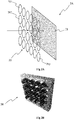
- Figure 1 shows a first example of a lightfield acquisition device. More specifically, figure 1 shows a plenoptic camera 1, according to a particular embodiment of the present principles.
- the plenoptic camera 1 comprises a lens unit 101 (corresponding to an optical assembly) and a camera body 102.
- the lens unit 101 is advantageously adapted to be associated with the camera body 102.
- the camera body 102 comprises a photosensor array 13, which comprises a plurality m of photosensors 131, 132, 133 to 13m.
- Each photosensor corresponds to a pixel of the raw image of the scene acquired with the photosensor array, with each pixel encompassing a part (also called a point) of the scene.
- Data representative of the scene obtained with each photosensor form a set of lightfield data, the lightfield data forming a lightfield image.
- the lightfield image Before processing of the raw image (before demultiplexing and/or demosaicing), the lightfield image may correspond to the raw image according to a non-limitative example.
- the lightfield image may correspond to sub-aperture images according to another non-limitative example and after demosaicing the lightfield image may correspond to the set of views of the scene according to a further non-limitative example.
- the photosensor array 13 is shown with a relative small number of photosensors 131 to 13m.
- the number of photosensors is not limited by the illustration of figure 1 but extends to any number of photosensors, for example several thousand or several millions of photosensors.
- a pixel will correspond to a photosensor (e.g. corresponding to an array of 4088 x 3040 pixels / photosensors).
- a color filter array (CFA) 12 may be arranged on the photosensor array 13.
- the CFA 12 typically arranges RGB (Red, Green and Blue) color filters on the photosensor array, the RGB arrangement taking for the example the form of a Bayer filter mosaic.
- a CFA is arranged on the lenslet array 11 (in addition to the CFA 12 or in replacement of the CFA 12).
- the lens unit 101 comprises a first attaching part and the camera body 102 comprises a second attaching part, the first and second attaching parts being compatible with each other. Thanks to the first and second attaching parts, the lens unit 101 may be clipped onto the camera body 102 or the lens unit 101 may be screwed with the camera body 102.
- first and second attaching parts of a lens unit configured to be associated with a camera body may be found in the Japanese patent application JP2013-105151A , which was published on May 30, 2013.
- the first and second attaching parts are configured in such a way that, once the lens unit 101 and the camera body 102 have been put together, the lens unit 101 and the camera body 102 form a plenoptic camera configured for acquiring multiple views of a scene at each acquisition of the scene.
- the camera body 102 also comprises a lenslet array 11 comprising n microlenses 111, 112, 113, 11 n, n being an integer greater than or equal to 2.
- the lenslet array 11 is also called microlens array.
- the lenslet array 11 is shown with a relative small number of microlenses, but the number of microlenses may extend up to several thousand or even one or several million of microlenses.
- a group of photosensors of the photosensor array 13 are optically associated with each microlens 111 to 11 n of the lenslet array 11.
- each microlens 111 to 11 n of the lenslet array 11 is sized to correspond to an array of 2x1, 4x4 or 10x10 photosensors.
- a group of photosensors associated with a microlens (or said differently, a group of photosensors under the microlens) form a micro-image associated with this microlens, each photosensor of the group of photosensors forming a pixel of the micro-image.
- Each photosensor of the plurality of photosensors optically associated with one single microlens enables to acquire raw data representative of a pixel of the scene according to one position (acquisition of as many parallaxes as pixels).
- the lens unit 101 and the camera body 102 collectively form one single body and are assembled without being detachable.
- the lens unit 101 comprises a camera lens 10, also called a main lens or primary lens, which is advantageously formed of one or more lens elements, only one lens element 10 being depicted in figure 1 for clarity purpose.
- a camera lens 10 also called a main lens or primary lens, which is advantageously formed of one or more lens elements, only one lens element 10 being depicted in figure 1 for clarity purpose.
- the plenoptic camera 1 is equally of the type 1.0, corresponding to a plenoptic camera wherein the distance between the lenslet array 11 and the photosensor array 13 is equal to the microlenses focal length, or of the type 2.0 otherwise (also called focused plenoptic camera).
- Figures 2A and 2B show further examples of a lightfield acquisition device. More specifically, figure 2A and 2B each show a camera array 2A, 2B (also called multi-cameras array), according to two particular embodiments of the present principles.
- a camera array 2A, 2B also called multi-cameras array
- the camera array 2A comprises an array of lenses or micro-lenses, referenced 20, comprising several micro-lenses referenced 201, 202 to 20p with p being an integer corresponding to the number of micro-lenses, and one or several sensor arrays, referenced 21.
- the camera array 2A is without main lens.
- the array of lenses 20 may be a small device, which is commonly named a micro-lens array. It is worth noting that the camera array with a single sensor can be considered as a special case of plenoptic camera where the main lens has an infinite focal. According to a particular arrangement wherein the number of photosensors is equal to the number of micro-lenses, i.e.
- the camera array 20 may be seen as an arrangement of several individual cameras (for example micro-cameras) closely spaced from each other, such as a square arrangement (as illustrated in figure 2A ) or a quincunx arrangement for example.
- the camera array 2B corresponds to a rig of individual cameras each comprising a lens and a photosensor array.
- the cameras are spaced from each other, for example of a distance equal to a few centimetres or less, for example 5, 7 or 10 cm.
- the lightfield data (forming a so-called lightfield image) obtained with such a camera array 2A or 2B corresponds to the plurality of views of the scene, i.e. to the final views obtained by demultiplexing and demosaicing of the raw image obtained with a plenoptic camera such as the plenoptic camera of figure 1 .
- the cameras of the camera array are calibrated according to any known method, i.e. intrinsic and extrinsic parameters of the cameras are known.
- Figure 3 shows a schematic block diagram illustrating an example of an apparatus 3 for obtaining a focal stack and/or a depth map of a scene from lightfield data.
- the apparatus 3 comprises a processor 31, a storage unit 32, an input device 33, a display device 34, and an interface unit 35 which are connected by a bus 36.
- a processor 31 a storage unit 32, an input device 33, a display device 34, and an interface unit 35 which are connected by a bus 36.
- constituent elements of the computer apparatus 3 may be connected by a connection other than a bus connection using the bus 36.
- the processor 31 controls operations of the apparatus 3.
- the storage unit 32 stores at least one program to be executed by the processor 31, and various data, including data of 4D the light field images (lightfield data) captured and provided by a light field camera, parameters used by computations performed by the processor 31, intermediate data of computations performed by the processor 31, and so on.
- the processor 31 may be formed by any known and suitable hardware, or software, or a combination of hardware and software.
- the processor 31 may be formed by dedicated hardware such as a processing circuit, or by a programmable processing unit such as a CPU (Central Processing Unit) and/or GPUs (Graphical Processing Unit) that executes a program stored in a memory thereof.
- CPU Central Processing Unit
- GPUs Graphics
- the storage unit 32 may be formed by any suitable storage or means capable of storing the program, data, or the like in a computer-readable manner. Examples of the storage unit 32 include non-transitory computer-readable storage media such as semiconductor memory devices, and magnetic, optical, or magneto-optical recording media loaded into a read and write unit.
- the program causes the processor 31 to perform a process for obtaining a focal stack of images and/or determining a depth map of the scene, according to an embodiment of the present disclosure as described hereinafter with reference to Figure 8 .
- the input device 33 may be formed by a keyboard, a pointing device such as a mouse, or the like for use by the user to input commands, to make user's selections of objects of interest within the scene.
- the output device 34 may be formed by a display device to display, for example, a Graphical User Interface (GUI), images of the focal stack, or a depth map image.
- GUI Graphical User Interface
- the input device 33 and the output device 34 may be formed integrally by a touchscreen panel, for example.
- the interface unit 35 provides an interface between the apparatus 3 and an external apparatus.
- the interface unit 35 may be communicable with the external apparatus via cable or wireless communication.
- the external apparatus may be a light field camera.
- data of 4D light field images captured by the light field camera can be input from the light field camera to the apparatus 3 through the interface unit 35, then stored in the storage unit 32.
- the apparatus 3 is exemplary discussed as it is separated from the lightfield camera and they may communicate with each other via cable or wireless communication, however it should be noted that the apparatus 3 may be integrated with such a lightfield camera.
- processor 31 may comprise different modules and units embodying the functions carried out by apparatus 3 according to embodiments of the present disclosure, such as:
- modules and units may also be embodied in several processors 31 communicating and co-operating with each other.
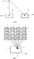
- Figure 4 shows a plurality of views obtained from lightfield data obtained with the lightfield camera 1 or 2, according to a particular and non-limiting embodiment of the present principles.
- the views 400 to 403, 410 to 413, 420 to 423 and 430 to 433 are represented with a matrix 4 of 4 rows and 4 columns, the two last digit of each reference number of each view indicating the row indicia and the column indicia the view belongs to.
- the view referenced 400 belongs to the first row having as indicia 0 and to the first column having as indicia 0 and the view referenced 421 belongs to the third row having as indicia 2 and to the second column having as indicia 1, the rows being indexed from 0 to 3 and the columns being indexed from 0 to 3.
- Each view 400 to 403, 410 to 413, 420 to 423 and 430 to 433 is an image of the scene according to a particular point of view, each view being associated with a different point of view.
- Each view comprises a plurality of pixels, for example N rows x M columns of pixels, each pixel having color information associated with, for example RGB color information or CMY (Cyan, Magenta, Yellow) color information.
- the views are for example obtained directly from the lightfield camera 2, one view being acquired directly through one lens of the array of lenses 20 or by processing the raw image acquired with the lightfield camera 1, i.e. by demultiplexing (as described in the article entitled “ Accurate Depth Map Estimation from a Lenslet Light Field Camera” by Hae-Gon Jeon Jaesik Park Gyeongmin Choe Jinsun Park,Yunsu Bok Yu-Wing Tai In So Kweon ) and demosaicing (as described in " Image demosaicing: a systematic survey” by Li, Gunturk and Zhang, Proc. SPIE, vol. 6822, p. 68221J (2008 )) the raw image.
- demultiplexing as described in the article entitled " Accurate Depth Map Estimation from a Lenslet Light Field Camera” by Hae-Gon Jeon Jaesik Park Gyeongmin Choe Jinsun Park,Yunsu Bok Yu-Wing Tai In So Kweon
- the demosaicing enables to recover a full color raw image, i.e. to recover full color information (for example RGB information) for the pixels of the raw image while the raw image acquired with the plenoptic image associates only one color component (R, G or B for example) with each pixel.
- the demultiplexing consists in reorganizing the pixels of the raw image in such a way that all pixels capturing the light rays with a certain angle of incidence are stored in the same image creating the so-called sub-aperture images.
- Each sub-aperture image is a projection of the scene under a different angle.
- the set of sub-aperture images creates a block matrix where the central image stores the pixels capturing the light rays perpendicular to the photosensor array.
- the number of views is not limited to 16 but extends to any integer number, for example 4 views, 10 views, 100 views or more.
- the arrangement of the views is not limited to a rectangular matrix arrangement but extends to any arrangement, for example a circular matrix arrangement, a quincunx matrix arrangement.
- FIG. 5 shows a focal stack 5 obtained from the matrix of views 4, according to a particular and non-limiting embodiment of the present principles.
- a focal stack is a collection of N re-focused images R(n) (with n ⁇ [1, N]) which define a cube of images, where N is a determined number of images, each re-focused images being called a slice.
- the N slices are computed for a depth value z varying linearly between a minimal depth value z min and a maximal depth value z max corresponding to a range of focalization distances, z min being for example equal to 0.2 m, 0.5 m, 1 m or more and z max being equal for example to 2m, 4m, 10m or more, z min and z max depending from the scene.
- the min max boundaries of z are for example set by a user in order to encompass slices with a focalization distance within z min and z max .
- the min max boundaries of z are associated with the lightfield camera and for example fixed by the manufacturer.
- Z n indicates the depth associated with the slice with index n.
- Z 1 is the depth associated with the first slice 501 of the focal stack 5
- Z 2 is the depth associated with the second slice 502 of the focal stack 5
- Z n is the depth associated with the n th slice 50n of the focal stack 5.
- a point of view is associated with the focal stack, this point of view being one of the points of view of the different views of the matrix 4 or any point of view.
- Figures 6 and 7 show operations to obtain the focal stack 5, according to a particular and non-limiting embodiment of the present principles.
- the example of figures 6 and 7 illustrates operations to obtain one of the slices of the focal stack, for example the slice 501. It is understood that the other slices of the focal stack 5 are obtained in a same way.
- the pixels of the views are projected in the space of the scene of a distance corresponding to the depth associated with the considered slice of the focal stack, i.e. of a distance Z 1 according to the example of figures 6 and 7 .
- rays originating from the point of view of the view 400 are traced through each pixel of the view 400 to define points of the scene corresponding to each pixel, the distance between a pixel 60 and its corresponding point 61 along the ray passing through the pixel 60 being equal to Z 1 .
- These points are projected into an image 600 with regard to a virtual camera position that corresponds to the point of view associated with the focal stack 5.
- the point 61 is projected into the pixel 62 of the image 600 with regard to the point of view associated with the focal stack 5.
- the image 600 that corresponds to the view 400 is warped with regard to the view due to the change of point of view.
- the operation of figure 6 is repeated for each view of the matrix to obtain one image corresponding to one view in the space associated with the point of view of the focal stack 5.
- the images obtained through the operation described with regard to figure 6 are illustrated on figure 7 and referenced 600 to 603, 610 to 613, 620 to 623 and 630 to 633, the images 600 to 603 corresponding to the views 400 to 403 respectively, the images 610 to 613 corresponding to the views 410 to 413 respectively, the images 620 to 623 corresponding to the views 420 to 423 respectively and the images 630 to 633 corresponding to the views 430 to 433 respectively.
- the slice 501 is obtained from the images 600 to 603, 610 to 613, 620 to 623 and 630 to 633.
- the slice 501 corresponds for example to an array of pixels, each pixel being referenced with a row index and a column index corresponding to the row and column said pixel belongs to.
- the number of rows and columns of the slice 501 is the same as the number of rows and columns of the images 600 to 603, 610 to 613, 620 to 623 and 630 to 633.
- a pixel 71 (with row index i and column index j) of the slice 501 is obtained as the sum of the pixels of the images 600 to 603, 610 to 613, 620 to 623 and 630 to 633 having the same row and column indicia, i.e. i and j respectively (illustrated with black dots on figure 7 ), divided by the number of images 600 to 603, 610 to 613, 620 to 623 and 630 to 633 (which corresponds to the number of views).
- the calculation is performed for each color channel in order to obtain a value for each color channel of the pixel 71.
- First and second operations are performed for each slice 501, 502 to 50n of the focal stack 5 to obtain the full focal stack 5.
- Figure 8 shows a method of obtaining a depth map using the matrix of views 4, according to a particular and non-limiting embodiment of the present principles.
- the matrix of views 4 is obtained, for example retrieved from a memory or directly from the photosensors array of the lightfield camera used to acquire the plurality of views of the scene.
- Each view of the matrix corresponds to an image of the scene according to a different point of view and comprises a plurality of pixels arranged under the form of rows and columns.
- the focal stack 5 is obtained from the matrix of views as described with regard to figures 6 and 7 .
- the focal stack comprises a set of N slices of the scene, N being an integer greater than or equal to 2, i.e. N images each representative of the scene at a different depth value Z n .
- a determined point of view is associated with the focal stack 5 that corresponds either to one of the points of view associated with the views of the matrix 4 or to a point of view different from the points of view associated with the views of the matrix 4.
- a slice comprises a set of first elements, for example arranged in the form of a matrix of rows and columns.
- a first element corresponds for example to one pixel or to a group of several pixels, for example a rectangle of PxQ pixels, P ⁇ 2 and Q ⁇ 2.
- a first element is identified with the row index and the column index it belongs to.
- First elements having same row index and same column index in the different slices of the focal stack are called corresponding first elements.
- Corresponding first elements are corresponding in the sense that they refer (or correspond) to one same point of the scene according to different points of view.
- an information representative of sharpness is obtained for each first element or for at least a part of the set of first elements (for example for a determined spatial area of the slices) of the slices of the focal stack.
- the information representative of sharpness represents the level of clearness of the first element.
- the information of sharpness for a considered first element is for example determined from a cost function measuring the similarity between the M samples (i.e. pixels) of the warped images (or equivalently of the views) used to obtain said first element (e.g. the M black dots of the images 600 to 603, 610 to 613, 620 to 623 and 630 to 633 of figure 7 used to obtain the first element 71). The more similar the M samples, the sharper is the considered first element.
- Different cost functions may be used to determine the information representative of sharpness, for example:
- the sharpness information is obtained by clustering the M samples of the views used to obtain the first element associated with said sharpness information.
- the sharpness information is for example the number of clusters obtained by the clustering operation.
- the clustering operation is for example based on the color information, samples having similar color information (i.e. with a difference less than a determined value) being grouped in a same cluster.
- a depth information e.g. a depth value
- the depth map is a matrix of rows and columns of second elements, the number of rows (respectively columns) of the depth map being equal to the number of rows (respectively columns) of each slice of the focal stack.
- a second element corresponds for example to one pixel or or to a group of several pixels, for example a rectangle of PxQ pixels, P ⁇ 2 and Q ⁇ 2.
- the size (i.e. the number of pixel(s) and the number of rows and columns of pixels) of a second element is the same as the size of a first element.
- Each second element (defined with its row and column indicia) has an associated first element (i.e. having same row and column indicia) in each slice of the focal stack.
- a set of corresponding M first elements of the focal stack is associated with one different second element of the depth map.
- the information of sharpness of said corresponding first elements is compared with each other to determine which first element is the sharpest.
- the sharpest first element is the one having the minimal cost function among all first elements of the considered set of corresponding first elements (i.e. first elements having same row and column numbers in the slices of the focal stack 5).
- the depth information to associate with the considered second element of the depth map corresponds to the depth value of the slice comprising the first element determined as the sharpest one in the set of corresponding first elements. For example, if the first element 71 of the slice 501 is determined as being the sharpest one (among all N first elements having same row and column indicia as the first element 71 in each of the N slices 501 to 50n), the depth information associated with the second element corresponding to the first element 71 is Z 1 .
- the sharpness information that is determined minimal for a set of corresponding first elements is associated with the second element corresponding to said set of corresponding first elements.
- the depth information is associated with the considered second element only when the information representative of sharpness associated with the first element belonging to the slice having as depth value the depth information is less than or equal to a determined value.
- the determined value is for example obtained empirically or set by a user, the determined value depending for example from the number of grey levels used to encode the color information.
- the depth information is associated with the considered second element only when the result of the cost function is less than or equal to a threshold, e.g. 5, 10, or 10 for an 8 bits coding.
- a threshold e.g. 5, 10, or 10 for an 8 bits coding.
- a step 85 it is checked whether each second element of the depth map has an associated sharpness information less than a determined level corresponding to the abovementioned determined value or determined number of cluster.
- the number of second elements or the percentage of second elements fulfilling the requirement of the checking operation i.e. sharpness information less than the determined level
- a determined number/percentage e.g. greater than or equal to 95 %, 98 % or 100 %
- the depth map is considered obtained and the process ends at step 87 with the obtaining of the depth map.
- the depth map is considered as partially obtained and step 86 is performed.
- the views used to obtain the focal stack are updated by removing the pixels used to obtain the first elements of the focal stack corresponding to the second elements of the depth map having a sharpness information less than the determined level.
- Color information of the concerned pixel is for example removed from the memory device used to store the views.
- the removing consists in not considering (or not taking into account) the "removed" pixels when determining the focal stack. Such an operation enables to remove the points of objects of the scene that are visible in all the views and to consider only the points of the scene that are visible on only a part of the views. Steps 82, 83, 84 are reiterated based on the updated views to obtain additional depth information, i.e.
- steps 82 to 84 enables to update the depth map with updated depth information and/or updated sharpness information for some of the second elements, i.e. for the second elements for which the previous sharpness information was less than the determined level after performing of the previous steps 82 to 84.
- Steps 85 is reiterated to check whether the percentage of second elements of the updated depth map having a sharpness information less than the determined level is greater than or equal to the determined percentage. If yes, the depth map is considered as being obtained and the process ends with step 87. If no, the process proceeds further with a new update of the views at step 86 and a reiteration of steps 82 to 85 until the depth map is considered as being obtained.
- one or more images of the scene is/are rendered and/or displayed on a display device using the depth information obtained with the operations described hereinabove.
- an All-In-Focus (AIF) image is rendered in the focal stack image plane.
- one or more foreground objects of the scene may be removed from the focal stack or from the AIF image by using the depth information. The background information is recovered provided it is visible in at least one of the views.
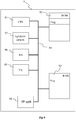
- Figure 9 diagrammatically illustrates a hardware embodiment of a telecommunication device 9, corresponding for example to a smartphone or a tablet that embodies a lightfield camera in accordance with an aspect of the present principles.
- the telecommunication device 9 comprises the following elements, connected to each other by a bus 94 of addresses and data that also transports a clock signal:
- register used in the description of memories 92 and 93 designates in each of the memories mentioned, a memory zone of low capacity as well as a memory zone of large capacity (enabling a whole programme to be stored or all or part of the data representing data received and decoded).
- the memory ROM 92 comprises in particular a "prog" program.
- the algorithms implementing the steps of the method specific to the present disclosure and described below are stored in the ROM 92 memory associated with the telecommunication device 9 implementing these steps.
- the microprocessor 91 loads and runs the instructions of these algorithms.
- the random access memory 93 notably comprises:
- the telecommunication device 9 may be implemented according to a purely hardware realisation, for example in the form of a dedicated component (for example in an ASIC (Application Specific Integrated Circuit) or FPGA (Field-Programmable Gate Array) or VLSI (Very Large Scale Integration) or of several electronic components embedded in an apparatus or even in a form of a mix of hardware elements and software elements.
- a dedicated component for example in an ASIC (Application Specific Integrated Circuit) or FPGA (Field-Programmable Gate Array) or VLSI (Very Large Scale Integration) or of several electronic components embedded in an apparatus or even in a form of a mix of hardware elements and software elements.
- ASIC Application Specific Integrated Circuit
- FPGA Field-Programmable Gate Array
- VLSI Very Large Scale Integration
- the radio interface 96 and the interface 95 are for example adapted for the reception and transmission of signals according to one or several telecommunication standards such as IEEE 802.11 (Wi-Fi), standards compliant with the IMT-2000 specifications (also called 3G), with 3GPP LTE (also called 4G), IEEE 802.15.1 (also called Bluetooth)...
- IEEE 802.11 Wi-Fi
- 3G 3rd Generation
- 4G 3rd Generation
- IEEE 802.15.1 also called Bluetooth
- the telecommunication device does not include any ROM but only RAM, the algorithms implementing the steps of the method specific to the present disclosure and described with regard to figure 8 being stored in the RAM.
- the telecommunication device 9 comprises a SSD (Solid-State Drive) memory instead of the ROM and/or the RAM.
- the present disclosure is not limited to an apparatus configured to obtain a depth map from lightfield data or to a method of obtaining lightfield data but also extends to a method/apparatus for displaying the depth map and/or to reconstruct one or more views of the scene or part of the scene, for example background part of the scene by removing foreground objects and by using the determined depth information stored in the depth map or to any device comprising such an apparatus or implementing such method(s), for example a telecommunication device.
- Telecommunication devices includes, for example, smartphones, smartwatches, tablets, computers, mobile phones, portable/personal digital assistants ("PDAs”), see-through glasses, Head-Mounted Display (HMD) and other devices that facilitate communication of information between end-users but also set-top-boxes.
- PDAs portable/personal digital assistants
- HMD Head-Mounted Display
- the method of obtaining a depth map described herein may be implemented by instructions being performed by a processor, and such instructions (and/or data values produced by an implementation) may be stored on a processor-readable medium such as, for example, an integrated circuit, a software carrier or other storage device such as, for example, a hard disk, a compact diskette (“CD"), an optical disc (such as, for example, a DVD, often referred to as a digital versatile disc or a digital video disc), a random access memory (“RAM”), or a read-only memory (“ROM”).
- the instructions may form an application program tangibly embodied on a processor-readable medium. Instructions may be, for example, in hardware, firmware, software, or a combination.
- a processor may be characterized, therefore, as, for example, both a device configured to carry out a process and a device that includes a processor-readable medium (such as a storage device) having instructions for carrying out a process. Further, a processor-readable medium may store, in addition to or in lieu of instructions, data values produced by an implementation.
- implementations may produce a variety of signals formatted to carry information that may be, for example, stored or transmitted.
- the information may include, for example, instructions for performing a method, or data produced by one of the described implementations.
- a signal may be formatted to carry as data the rules for writing or reading the syntax of a described embodiment, or to carry as data the actual syntax-values written by a described embodiment.
- Such a signal may be formatted, for example, as an electromagnetic wave (for example, using a radio frequency portion of spectrum) or as a baseband signal.
- the formatting may include, for example, encoding a data stream and modulating a carrier with the encoded data stream.
- the information that the signal carries may be, for example, analog or digital information.
- the signal may be transmitted over a variety of different wired or wireless links, as is known.
- the signal may be stored on a processor-readable medium.
Landscapes
- Engineering & Computer Science (AREA)
- Computer Vision & Pattern Recognition (AREA)
- Physics & Mathematics (AREA)
- General Physics & Mathematics (AREA)
- Theoretical Computer Science (AREA)
- Studio Devices (AREA)
Abstract
A method and device to obtain a depth map associated with a scene represented with different views. Following operations are performed:
a) obtaining (82) a focal stack from the views, the focal stack comprising slices each representative of the scene at a different depth value, each slice corresponding to a matrix of first elements;
b) for each first element in each slice, determining (83) a first sharpness value from pixels of the views used to obtain said each first element;
c) for each second element of said depth map, associating a second sharpness value corresponding to the minimal first sharpness value among the plurality of first sharpness values associated with the first elements having same row and column indices as said each second element;
d) for at least some second elements, associating (84) a depth information that corresponds to the depth value of the slice of the focal stack comprising the first element having the minimal sharpness value;
e) updating (86) the views by removing pixels used to obtain the first elements corresponding to second elements having an associated second sharpness value less than or equal to a determined level;
f) reiterating operations a) to d) based on the updated views.
a) obtaining (82) a focal stack from the views, the focal stack comprising slices each representative of the scene at a different depth value, each slice corresponding to a matrix of first elements;
b) for each first element in each slice, determining (83) a first sharpness value from pixels of the views used to obtain said each first element;
c) for each second element of said depth map, associating a second sharpness value corresponding to the minimal first sharpness value among the plurality of first sharpness values associated with the first elements having same row and column indices as said each second element;
d) for at least some second elements, associating (84) a depth information that corresponds to the depth value of the slice of the focal stack comprising the first element having the minimal sharpness value;
e) updating (86) the views by removing pixels used to obtain the first elements corresponding to second elements having an associated second sharpness value less than or equal to a determined level;
f) reiterating operations a) to d) based on the updated views.
Description
- The present disclosure relates to light-field imaging, and to technologies for acquiring and processing light-field data. The present disclosure also relates to a method and apparatus to obtain a depth map associated with a scene from a lightfield content, and finds applications in the domain of image or video rendering for example.
- This section is intended to introduce the reader to various aspects of art, which may be related to various aspects of the present disclosure that are described and/or claimed below. This discussion is believed to be helpful in providing the reader with background information to facilitate a better understanding of the various aspects of the present invention. Accordingly, it should be understood that these statements are to be read in this light, and not as admissions of prior art.
- Conventional image capture devices render a three-dimensional scene onto a two-dimensional sensor. During operation, a conventional capture device captures a two-dimensional (2-D) image representing an amount of light that reaches a photosensor (or photodetector) within the device. However, this 2-D image contains no information about the directional distribution of the light rays that reach the photosensor (which may be referred to as the light-field). Depth, for example, is lost during the acquisition. Thus, a conventional capture device does not store most of the information about the light distribution from the scene.
- Light-field capture devices (also referred to as "light-field data acquisition devices") have been designed to measure a four-dimensional (4D) light-field of the scene by capturing the light from different viewpoints of that scene. Thus, by measuring the amount of light traveling along each beam of light that intersects the photosensor, these devices can capture additional optical information (information about the directional distribution of the bundle of light rays) for providing new imaging applications by post-processing. The information acquired/obtained by a light-field capture device is referred to as the light-field data. Light-field capture devices are defined herein as any devices that are capable of capturing light-field data. There are several types of light-field capture devices, among which plenoptic devices, which use a microlens array placed between the image sensor and the main lens, and camera array, where all cameras image onto a single shared image sensor.
- Light-field data processing comprises notably, but is not limited to, generating refocused images of a scene, generating perspective views of a scene, generating depth maps of a scene, generating extended depth of field (EDOF) images, generating stereoscopic images, generating a focal stack, (which comprises a collection of images, each of them being focused at a different focalization distance), and/or any combination of these.
- Determining depth information associated with a scene from light-field data and associated focal stack is for example described in the article entitled " Reconstructing Occluded Surfaces using Synthetic Apertures: Stereo, Focus and Robust Measures", by Vaibhav Vaish et al., in Computer Vision and Pattern Recognition, 2006 IEEE Computer Society Conference on Vol. 2. The techniques described let room for improvement, for example for determining depth associated with occlusion points, i.e. points that are not fully visible, i.e. not visible in all the views obtained from the light-field data.
- The present disclosure relates to an apparatus configured and/or adapted to obtain a depth map associated with a scene, the scene being represented in a plurality of views, a different point of view being associated with each view of the plurality of views, the apparatus comprising at least one processor configured to perform following operations:
- a) obtaining a focal stack from the plurality of views, the focal stack comprising a plurality of slices each representative of the scene at a different depth value, each slice of the plurality of slices corresponding to a matrix of first elements;
- b) for each first element of a set of first elements in each slice of the plurality of slices, determining a first sharpness value from pixels of the views used to obtain said each first element;
- c) for each second element of a set of second elements comprised in the depth map, associating a second sharpness value corresponding to the minimal first sharpness value among the plurality of first sharpness values associated with the first elements having same row and column indices as said each second element;
- d) for each second element of at least a part of the set of second elements, associating a depth information with said each second element, the associated depth information corresponding to the depth value of the slice of the focal stack comprising the first element having the minimal sharpness value;
- e) updating the plurality of views by removing pixels of the plurality of views used to obtain the first elements corresponding to second elements having an associated second sharpness value less than or equal to a determined level;
- f) reiterating operations a) to d) based on the updated plurality of views.
- The present disclosure also relates to a method of obtaining a depth map associated with a scene, said scene being represented in a plurality of views, a different point of view being associated with each view of said plurality of views, the method comprising the operations a) to f) performed in the apparatus.
- According to a characteristic, the first sharpness value corresponds to:
- a result of a cost function measuring a similarity between pixels of the plurality of views used to obtain said each first element; or
- a result of a clustering of said pixels of the plurality of views used to obtain said each first element.
- According to a particular characteristic, the first element and the second element correspond to one pixel or to a group of at least two pixels.
- According to a specific characteristic, the apparatus further comprises a receiver configured to receive the plurality of views from a camera array, the number of cameras of the camera array corresponding to the number of views.
- According to another characteristic, the operations e) and f) are reiterated until the depth map comprises a percentage of second elements having a sharpness value less than or equal to the determined level greater than or equal to a determined percentage.
- According to another characteristic, the operation of associating a depth information with said each second element is performed only for second elements having an associated second sharpness value less than or equal to the determined level.
- The present disclosure also relates to a computer program product comprising instructions of program code for executing steps of the method of obtaining a depth map, when the program is executed on a computing device.
- The present disclosure also relates to a processor readable medium having stored therein instructions for causing a processor to perform at least a step of the method of obtaining a depth map.
- The present disclosure also related to a communication terminal comprising a lightfield camera and/or a processing unit configured to implement the method of obtaining a depth map.
- The present disclosure will be better understood, and other specific features and advantages will emerge upon reading the following description, the description making reference to the annexed drawings wherein:
-
figure 1 shows a first example of a lightfield camera, according to a particular embodiment of the present principles; -
figures 2A and 2B show second examples of a lightfield camera, according to particular embodiments of the present principles; -
figure 3 shows a processing unit configured to process data provided by the lightfield camera offigure 1 or2 and/or to implement the method offigure 8 , according to a particular embodiment of the present principles; -
figure 4 shows a matrix of views obtained with lightfield data obtained with the lightfield camera offigure 1 or2 , according to a particular embodiment of the present principles; -
figure 5 shows a focal stack obtained from the matrix of views offigure 4 , according to a particular embodiment of the present principles; -
figure 6 and 7 show operations to obtain the focal stack offigure 5 , according to a particular embodiment of the present principles; -
figure 8 shows a method of obtaining a depth map using the matrix of views offigure 4 , according to a particular embodiment of the present principles; -
figure 9 shows a telecommunication device comprising the lightfield camera offigure 1 or2 , according to a particular embodiment of the present principles. - The subject matter is now described with reference to the drawings, wherein like reference numerals are used to refer to like elements throughout. In the following description, for purposes of explanation, numerous specific details are set forth in order to provide a thorough understanding of the subject matter. It can be evident, however, that subject matter embodiments can be practiced without these specific details.
-
Figure 1 shows a first example of a lightfield acquisition device. More specifically,figure 1 shows aplenoptic camera 1, according to a particular embodiment of the present principles. Theplenoptic camera 1 comprises a lens unit 101 (corresponding to an optical assembly) and acamera body 102. - The
lens unit 101 is advantageously adapted to be associated with thecamera body 102. Thecamera body 102 comprises aphotosensor array 13, which comprises a plurality m ofphotosensors photosensor array 13 is shown with a relative small number ofphotosensors 131 to 13m. Naturally, the number of photosensors is not limited by the illustration offigure 1 but extends to any number of photosensors, for example several thousand or several millions of photosensors. For example in a 12.4 megapixel camera, a pixel will correspond to a photosensor (e.g. corresponding to an array of 4088 x 3040 pixels / photosensors). A color filter array (CFA) 12 may be arranged on thephotosensor array 13. TheCFA 12 typically arranges RGB (Red, Green and Blue) color filters on the photosensor array, the RGB arrangement taking for the example the form of a Bayer filter mosaic. According to a variant, a CFA is arranged on the lenslet array 11 (in addition to theCFA 12 or in replacement of the CFA 12). For associating thelens unit 101 with thecamera body 102, thelens unit 101 comprises a first attaching part and thecamera body 102 comprises a second attaching part, the first and second attaching parts being compatible with each other. Thanks to the first and second attaching parts, thelens unit 101 may be clipped onto thecamera body 102 or thelens unit 101 may be screwed with thecamera body 102. An example of such first and second attaching parts of a lens unit configured to be associated with a camera body may be found in the Japanese patent applicationJP2013-105151A lens unit 101 and thecamera body 102 have been put together, thelens unit 101 and thecamera body 102 form a plenoptic camera configured for acquiring multiple views of a scene at each acquisition of the scene. To this end, thecamera body 102 also comprises alenslet array 11 comprisingn microlenses lenslet array 11 is also called microlens array. For purposes of illustration, thelenslet array 11 is shown with a relative small number of microlenses, but the number of microlenses may extend up to several thousand or even one or several million of microlenses. A group of photosensors of thephotosensor array 13 are optically associated with eachmicrolens 111 to 11 n of thelenslet array 11. For example, eachmicrolens 111 to 11 n of thelenslet array 11 is sized to correspond to an array of 2x1, 4x4 or 10x10 photosensors. A group of photosensors associated with a microlens (or said differently, a group of photosensors under the microlens) form a micro-image associated with this microlens, each photosensor of the group of photosensors forming a pixel of the micro-image. Each photosensor of the plurality of photosensors optically associated with one single microlens enables to acquire raw data representative of a pixel of the scene according to one position (acquisition of as many parallaxes as pixels). According to a variant, thelens unit 101 and thecamera body 102 collectively form one single body and are assembled without being detachable. - The
lens unit 101 comprises acamera lens 10, also called a main lens or primary lens, which is advantageously formed of one or more lens elements, only onelens element 10 being depicted infigure 1 for clarity purpose. - The
plenoptic camera 1 is equally of the type 1.0, corresponding to a plenoptic camera wherein the distance between thelenslet array 11 and thephotosensor array 13 is equal to the microlenses focal length, or of the type 2.0 otherwise (also called focused plenoptic camera). -
Figures 2A and 2B show further examples of a lightfield acquisition device. More specifically,figure 2A and 2B each show acamera array - The
camera array 2A comprises an array of lenses or micro-lenses, referenced 20, comprising several micro-lenses referenced 201, 202 to 20p with p being an integer corresponding to the number of micro-lenses, and one or several sensor arrays, referenced 21. Thecamera array 2A is without main lens. The array oflenses 20 may be a small device, which is commonly named a micro-lens array. It is worth noting that the camera array with a single sensor can be considered as a special case of plenoptic camera where the main lens has an infinite focal. According to a particular arrangement wherein the number of photosensors is equal to the number of micro-lenses, i.e. one photosensor is optically associated with one micro-lens, thecamera array 20 may be seen as an arrangement of several individual cameras (for example micro-cameras) closely spaced from each other, such as a square arrangement (as illustrated infigure 2A ) or a quincunx arrangement for example. - The
camera array 2B corresponds to a rig of individual cameras each comprising a lens and a photosensor array. The cameras are spaced from each other, for example of a distance equal to a few centimetres or less, for example 5, 7 or 10 cm. - The lightfield data (forming a so-called lightfield image) obtained with such a
camera array figure 1 . The cameras of the camera array are calibrated according to any known method, i.e. intrinsic and extrinsic parameters of the cameras are known. -
Figure 3 shows a schematic block diagram illustrating an example of anapparatus 3 for obtaining a focal stack and/or a depth map of a scene from lightfield data. - The
apparatus 3 comprises aprocessor 31, astorage unit 32, aninput device 33, adisplay device 34, and aninterface unit 35 which are connected by abus 36. Of course, constituent elements of thecomputer apparatus 3 may be connected by a connection other than a bus connection using thebus 36. - The
processor 31 controls operations of theapparatus 3. Thestorage unit 32 stores at least one program to be executed by theprocessor 31, and various data, including data of 4D the light field images (lightfield data) captured and provided by a light field camera, parameters used by computations performed by theprocessor 31, intermediate data of computations performed by theprocessor 31, and so on. Theprocessor 31 may be formed by any known and suitable hardware, or software, or a combination of hardware and software. For example, theprocessor 31 may be formed by dedicated hardware such as a processing circuit, or by a programmable processing unit such as a CPU (Central Processing Unit) and/or GPUs (Graphical Processing Unit) that executes a program stored in a memory thereof. - The
storage unit 32 may be formed by any suitable storage or means capable of storing the program, data, or the like in a computer-readable manner. Examples of thestorage unit 32 include non-transitory computer-readable storage media such as semiconductor memory devices, and magnetic, optical, or magneto-optical recording media loaded into a read and write unit. The program causes theprocessor 31 to perform a process for obtaining a focal stack of images and/or determining a depth map of the scene, according to an embodiment of the present disclosure as described hereinafter with reference toFigure 8 . - The
input device 33 may be formed by a keyboard, a pointing device such as a mouse, or the like for use by the user to input commands, to make user's selections of objects of interest within the scene. Theoutput device 34 may be formed by a display device to display, for example, a Graphical User Interface (GUI), images of the focal stack, or a depth map image. Theinput device 33 and theoutput device 34 may be formed integrally by a touchscreen panel, for example. - The
interface unit 35 provides an interface between theapparatus 3 and an external apparatus. Theinterface unit 35 may be communicable with the external apparatus via cable or wireless communication. In this embodiment, the external apparatus may be a light field camera. In this case, data of 4D light field images captured by the light field camera can be input from the light field camera to theapparatus 3 through theinterface unit 35, then stored in thestorage unit 32. - In this embodiment the
apparatus 3 is exemplary discussed as it is separated from the lightfield camera and they may communicate with each other via cable or wireless communication, however it should be noted that theapparatus 3 may be integrated with such a lightfield camera. - Although only one
processor 31 is shown onfigure 3 , it must be understood that such a processor may comprise different modules and units embodying the functions carried out byapparatus 3 according to embodiments of the present disclosure, such as: - a module for determining the focal stack as the set of consecutive focused images;
- a module for identifying objects of interest in the scene;
- a module for assessing the depth of objects of interest;
- a module for determining the number of focused images to be associated to each object of interest;
- a depth computation module for calculating depths from the light field data set or from a matrix of views generated from the light field data set;
- a computing unit for computing the position of objects of interest in the scene from the calculated depths.
- These modules and units may also be embodied in
several processors 31 communicating and co-operating with each other. -
Figure 4 shows a plurality of views obtained from lightfield data obtained with thelightfield camera 1 or 2, according to a particular and non-limiting embodiment of the present principles. In the example offigure 4 , theviews 400 to 403, 410 to 413, 420 to 423 and 430 to 433 are represented with amatrix 4 of 4 rows and 4 columns, the two last digit of each reference number of each view indicating the row indicia and the column indicia the view belongs to. For example, the view referenced 400 belongs to the first row having as indicia 0 and to the first column having as indicia 0 and the view referenced 421 belongs to the third row having as indicia 2 and to the second column having asindicia 1, the rows being indexed from 0 to 3 and the columns being indexed from 0 to 3. - Each
view 400 to 403, 410 to 413, 420 to 423 and 430 to 433 is an image of the scene according to a particular point of view, each view being associated with a different point of view. Each view comprises a plurality of pixels, for example N rows x M columns of pixels, each pixel having color information associated with, for example RGB color information or CMY (Cyan, Magenta, Yellow) color information. - The views are for example obtained directly from the lightfield camera 2, one view being acquired directly through one lens of the array of
lenses 20 or by processing the raw image acquired with thelightfield camera 1, i.e. by demultiplexing (as described in the article entitled " Accurate Depth Map Estimation from a Lenslet Light Field Camera" by Hae-Gon Jeon Jaesik Park Gyeongmin Choe Jinsun Park,Yunsu Bok Yu-Wing Tai In So Kweon) and demosaicing (as described in " Image demosaicing: a systematic survey" by Li, Gunturk and Zhang, Proc. SPIE, vol. 6822, p. 68221J (2008 )) the raw image. The demosaicing enables to recover a full color raw image, i.e. to recover full color information (for example RGB information) for the pixels of the raw image while the raw image acquired with the plenoptic image associates only one color component (R, G or B for example) with each pixel. The demultiplexing consists in reorganizing the pixels of the raw image in such a way that all pixels capturing the light rays with a certain angle of incidence are stored in the same image creating the so-called sub-aperture images. Each sub-aperture image is a projection of the scene under a different angle. The set of sub-aperture images creates a block matrix where the central image stores the pixels capturing the light rays perpendicular to the photosensor array. - Naturally, the number of views is not limited to 16 but extends to any integer number, for example 4 views, 10 views, 100 views or more. The arrangement of the views is not limited to a rectangular matrix arrangement but extends to any arrangement, for example a circular matrix arrangement, a quincunx matrix arrangement.
-
Figure 5 shows afocal stack 5 obtained from the matrix ofviews 4, according to a particular and non-limiting embodiment of the present principles. A focal stack is a collection of N re-focused images R(n) (with n ∈ [1, N]) which define a cube of images, where N is a determined number of images, each re-focused images being called a slice. The N slices are computed for a depth value z varying linearly between a minimal depth value zmin and a maximal depth value zmax corresponding to a range of focalization distances, zmin being for example equal to 0.2 m, 0.5 m, 1 m or more and zmax being equal for example to 2m, 4m, 10m or more, zmin and zmax depending from the scene. The min max boundaries of z are for example set by a user in order to encompass slices with a focalization distance within zmin and zmax. According to a variant, the min max boundaries of z are associated with the lightfield camera and for example fixed by the manufacturer. Zn indicates the depth associated with the slice with index n. For example, Z1 is the depth associated with thefirst slice 501 of thefocal stack 5, Z2 is the depth associated with thesecond slice 502 of thefocal stack 5 and Zn is the depth associated with the nth slice 50n of thefocal stack 5. A point of view is associated with the focal stack, this point of view being one of the points of view of the different views of thematrix 4 or any point of view. -
Figures 6 and 7 show operations to obtain thefocal stack 5, according to a particular and non-limiting embodiment of the present principles. The example offigures 6 and 7 illustrates operations to obtain one of the slices of the focal stack, for example theslice 501. It is understood that the other slices of thefocal stack 5 are obtained in a same way. - In a first operation illustrated on
figure 6 , the pixels of the views are projected in the space of the scene of a distance corresponding to the depth associated with the considered slice of the focal stack, i.e. of a distance Z1 according to the example offigures 6 and 7 . Said differently, rays originating from the point of view of theview 400 are traced through each pixel of theview 400 to define points of the scene corresponding to each pixel, the distance between apixel 60 and itscorresponding point 61 along the ray passing through thepixel 60 being equal to Z1. These points are projected into animage 600 with regard to a virtual camera position that corresponds to the point of view associated with thefocal stack 5. For example, thepoint 61 is projected into thepixel 62 of theimage 600 with regard to the point of view associated with thefocal stack 5. Theimage 600 that corresponds to theview 400 is warped with regard to the view due to the change of point of view. The operation offigure 6 is repeated for each view of the matrix to obtain one image corresponding to one view in the space associated with the point of view of thefocal stack 5. - The images obtained through the operation described with regard to
figure 6 are illustrated onfigure 7 and referenced 600 to 603, 610 to 613, 620 to 623 and 630 to 633, theimages 600 to 603 corresponding to theviews 400 to 403 respectively, theimages 610 to 613 corresponding to theviews 410 to 413 respectively, theimages 620 to 623 corresponding to theviews 420 to 423 respectively and theimages 630 to 633 corresponding to theviews 430 to 433 respectively. - In a second operation illustrated on
figure 7 , theslice 501 is obtained from theimages 600 to 603, 610 to 613, 620 to 623 and 630 to 633. Theslice 501 corresponds for example to an array of pixels, each pixel being referenced with a row index and a column index corresponding to the row and column said pixel belongs to. The number of rows and columns of theslice 501 is the same as the number of rows and columns of theimages 600 to 603, 610 to 613, 620 to 623 and 630 to 633. A pixel 71 (with row index i and column index j) of theslice 501 is obtained as the sum of the pixels of theimages 600 to 603, 610 to 613, 620 to 623 and 630 to 633 having the same row and column indicia, i.e. i and j respectively (illustrated with black dots onfigure 7 ), divided by the number ofimages 600 to 603, 610 to 613, 620 to 623 and 630 to 633 (which corresponds to the number of views). The calculation is performed for each color channel in order to obtain a value for each color channel of thepixel 71. - First and second operations are performed for each
slice focal stack 5 to obtain the fullfocal stack 5. -
Figure 8 shows a method of obtaining a depth map using the matrix ofviews 4, according to a particular and non-limiting embodiment of the present principles. - In a
step 81, the matrix ofviews 4 is obtained, for example retrieved from a memory or directly from the photosensors array of the lightfield camera used to acquire the plurality of views of the scene. Each view of the matrix corresponds to an image of the scene according to a different point of view and comprises a plurality of pixels arranged under the form of rows and columns. - In a
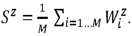
step 82, thefocal stack 5 is obtained from the matrix of views as described with regard tofigures 6 and 7 . The focal stack comprises a set of N slices of the scene, N being an integer greater than or equal to 2, i.e. N images each representative of the scene at a different depth value Zn. A determined point of view is associated with thefocal stack 5 that corresponds either to one of the points of view associated with the views of thematrix 4 or to a point of view different from the points of view associated with the views of thematrix 4. A slice comprises a set of first elements, for example arranged in the form of a matrix of rows and columns. A first element corresponds for example to one pixel or to a group of several pixels, for example a rectangle of PxQ pixels, P ≥ 2 and Q ≥ 2. A first element is identified with the row index and the column index it belongs to. First elements having same row index and same column index in the different slices of the focal stack are called corresponding first elements. Corresponding first elements are corresponding in the sense that they refer (or correspond) to one same point of the scene according to different points of view. - For a considered depth value z in an interval [Zmin, Zmax], the images Ii=1...M corresponding to the M views are warped accordingly with regard to a virtual camera position corresponding to the point of view associated with the focal stack. The warped images at depth Zn are denoted

- In a
step 83, an information representative of sharpness is obtained for each first element or for at least a part of the set of first elements (for example for a determined spatial area of the slices) of the slices of the focal stack. The information representative of sharpness represents the level of clearness of the first element. The information of sharpness for a considered first element (e.g. thefirst element 71 offigure 7 ) is for example determined from a cost function measuring the similarity between the M samples (i.e. pixels) of the warped images (or equivalently of the views) used to obtain said first element (e.g. the M black dots of theimages 600 to 603, 610 to 613, 620 to 623 and 630 to 633 offigure 7 used to obtain the first element 71). The more similar the M samples, the sharper is the considered first element. Different cost functions (CF) may be used to determine the information representative of sharpness, for example: - Cost function based on variance:

- Cost function based on color differences:
- According to a variant, the sharpness information is obtained by clustering the M samples of the views used to obtain the first element associated with said sharpness information. According to this variant, the sharpness information is for example the number of clusters obtained by the clustering operation. The clustering operation is for example based on the color information, samples having similar color information (i.e. with a difference less than a determined value) being grouped in a same cluster.
- In a
step 84, a depth information, e.g. a depth value, is determined for each second element or for at least a part of the second elements of a depth map associated with the scene according to the point of view of thefocal stack 5. The depth map is a matrix of rows and columns of second elements, the number of rows (respectively columns) of the depth map being equal to the number of rows (respectively columns) of each slice of the focal stack. A second element corresponds for example to one pixel or or to a group of several pixels, for example a rectangle of PxQ pixels, P ≥ 2 and Q ≥ 2. The size (i.e. the number of pixel(s) and the number of rows and columns of pixels) of a second element is the same as the size of a first element. Each second element (defined with its row and column indicia) has an associated first element (i.e. having same row and column indicia) in each slice of the focal stack. In other words, a set of corresponding M first elements of the focal stack is associated with one different second element of the depth map. Considering a set of corresponding first elements of the focal stack (associated with one considered second element), the information of sharpness of said corresponding first elements is compared with each other to determine which first element is the sharpest. When the information of sharpness corresponds to the result of a cost function, the sharpest first element is the one having the minimal cost function among all first elements of the considered set of corresponding first elements (i.e. first elements having same row and column numbers in the slices of the focal stack 5). The depth information to associate with the considered second element of the depth map (associated with said considered set of corresponding first elements) corresponds to the depth value of the slice comprising the first element determined as the sharpest one in the set of corresponding first elements. For example, if thefirst element 71 of theslice 501 is determined as being the sharpest one (among all N first elements having same row and column indicia as thefirst element 71 in each of the N slices 501 to 50n), the depth information associated with the second element corresponding to thefirst element 71 is Z1. The depth value Z(x) to associate with a considered second element 'x' (with x corresponding for example to the row and column indicia identifying the second element and corresponding first elements) is obtained for example with:
- According to a variant, the depth information is associated with the considered second element only when the information representative of sharpness associated with the first element belonging to the slice having as depth value the depth information is less than or equal to a determined value. The determined value is for example obtained empirically or set by a user, the determined value depending for example from the number of grey levels used to encode the color information. For example, if the sharpness information corresponds to the result of a cost function, the depth information is associated with the considered second element only when the result of the cost function is less than or equal to a threshold, e.g. 5, 10, or 10 for an 8 bits coding. If the sharpness information corresponds to the number of clusters obtained when clustering the M samples, the depth information is associated with the considered second element only when the number of cluster is equal to a determined number of cluster equal to 1.
- In a
step 85, it is checked whether each second element of the depth map has an associated sharpness information less than a determined level corresponding to the abovementioned determined value or determined number of cluster. When the number of second elements or the percentage of second elements fulfilling the requirement of the checking operation (i.e. sharpness information less than the determined level) is greater than or equal to a determined number/percentage (e.g. greater than or equal to 95 %, 98 % or 100 %), then the depth map is considered obtained and the process ends atstep 87 with the obtaining of the depth map. When the number of second elements or the percentage of second elements fulfilling the requirement of the checking operation is less than said determined number/percentage, then the depth map is considered as partially obtained andstep 86 is performed. - In the
step 86, the views used to obtain the focal stack are updated by removing the pixels used to obtain the first elements of the focal stack corresponding to the second elements of the depth map having a sharpness information less than the determined level. Color information of the concerned pixel is for example removed from the memory device used to store the views. According to another example, the removing consists in not considering (or not taking into account) the "removed" pixels when determining the focal stack. Such an operation enables to remove the points of objects of the scene that are visible in all the views and to consider only the points of the scene that are visible on only a part of the views.Steps previous step 85. An updated focal stack is obtained from the updated views, the updated focal stack having the same point of view as thefocal stack 5. An updated sharpness information is calculated for the first elements obtained from the updated views and an updated depth information is obtained as described with regard to step 84 for the second elements corresponding to the first elements obtained from the updated views. The reiteration ofsteps 82 to 84 enables to update the depth map with updated depth information and/or updated sharpness information for some of the second elements, i.e. for the second elements for which the previous sharpness information was less than the determined level after performing of theprevious steps 82 to 84. -
Steps 85 is reiterated to check whether the percentage of second elements of the updated depth map having a sharpness information less than the determined level is greater than or equal to the determined percentage. If yes, the depth map is considered as being obtained and the process ends withstep 87. If no, the process proceeds further with a new update of the views atstep 86 and a reiteration ofsteps 82 to 85 until the depth map is considered as being obtained. - In an optional step, one or more images of the scene is/are rendered and/or displayed on a display device using the depth information obtained with the operations described hereinabove. For example, an All-In-Focus (AIF) image is rendered in the focal stack image plane. According to a variant, one or more foreground objects of the scene may be removed from the focal stack or from the AIF image by using the depth information. The background information is recovered provided it is visible in at least one of the views.
-
Figure 9 diagrammatically illustrates a hardware embodiment of atelecommunication device 9, corresponding for example to a smartphone or a tablet that embodies a lightfield camera in accordance with an aspect of the present principles. - The
telecommunication device 9 comprises the following elements, connected to each other by abus 94 of addresses and data that also transports a clock signal: - a microprocessor 91 (or CPU),
- a non-volatile memory of ROM (Read Only Memory)
type 92, - a Random Access Memory or
RAM 93, - a
radio interface 96, - an
interface 95 adapted for the transmission of data, - a
lightfield camera 97, corresponding for example to theplenoptic camera 1 offigure 1 or to the multi-camera array 2 offigure 2 , - an MMI (Man Machine Interface) 98 adapted for displaying information for a user and/or inputting data or parameters.
- It is noted that the word "register" used in the description of
memories - The
memory ROM 92 comprises in particular a "prog" program. - The algorithms implementing the steps of the method specific to the present disclosure and described below are stored in the
ROM 92 memory associated with thetelecommunication device 9 implementing these steps. When powered up, themicroprocessor 91 loads and runs the instructions of these algorithms. - The
random access memory 93 notably comprises: - in a register, the operating programme of the
microprocessor 91 responsible for switching on thetelecommunication device 9, - reception parameters (for example parameters for modulation, encoding, MIMO, recurrence of frames),
- transmission parameters (for example parameters for modulation, encoding, MIMO, recurrence of frames),
- incoming data corresponding to the data received and decoded by the
receiver 96, - decoded data formed to be transmitted at the interface to the
application 95, - parameters of the lightfield camera,
- lightfield data forming the raw image and/or the views,
- data representative of the focal stack,
- information representative of depth, e.g. comprised in a depth map.
- Other structures of the
telecommunication device 9 than those described with respect tofigure 9 are compatible with the present disclosure. In particular, according to variants, the telecommunication device may be implemented according to a purely hardware realisation, for example in the form of a dedicated component (for example in an ASIC (Application Specific Integrated Circuit) or FPGA (Field-Programmable Gate Array) or VLSI (Very Large Scale Integration) or of several electronic components embedded in an apparatus or even in a form of a mix of hardware elements and software elements. - The
radio interface 96 and theinterface 95 are for example adapted for the reception and transmission of signals according to one or several telecommunication standards such as IEEE 802.11 (Wi-Fi), standards compliant with the IMT-2000 specifications (also called 3G), with 3GPP LTE (also called 4G), IEEE 802.15.1 (also called Bluetooth)... - According to a variant, the telecommunication device does not include any ROM but only RAM, the algorithms implementing the steps of the method specific to the present disclosure and described with regard to
figure 8 being stored in the RAM. According to another variant, thetelecommunication device 9 comprises a SSD (Solid-State Drive) memory instead of the ROM and/or the RAM. - Naturally, the present disclosure is not limited to the embodiments previously described.
- In particular, the present disclosure is not limited to an apparatus configured to obtain a depth map from lightfield data or to a method of obtaining lightfield data but also extends to a method/apparatus for displaying the depth map and/or to reconstruct one or more views of the scene or part of the scene, for example background part of the scene by removing foreground objects and by using the determined depth information stored in the depth map or to any device comprising such an apparatus or implementing such method(s), for example a telecommunication device.
- Telecommunication devices includes, for example, smartphones, smartwatches, tablets, computers, mobile phones, portable/personal digital assistants ("PDAs"), see-through glasses, Head-Mounted Display (HMD) and other devices that facilitate communication of information between end-users but also set-top-boxes.
- The method of obtaining a depth map described herein may be implemented by instructions being performed by a processor, and such instructions (and/or data values produced by an implementation) may be stored on a processor-readable medium such as, for example, an integrated circuit, a software carrier or other storage device such as, for example, a hard disk, a compact diskette ("CD"), an optical disc (such as, for example, a DVD, often referred to as a digital versatile disc or a digital video disc), a random access memory ("RAM"), or a read-only memory ("ROM"). The instructions may form an application program tangibly embodied on a processor-readable medium. Instructions may be, for example, in hardware, firmware, software, or a combination. Instructions may be found in, for example, an operating system, a separate application, or a combination of the two. A processor may be characterized, therefore, as, for example, both a device configured to carry out a process and a device that includes a processor-readable medium (such as a storage device) having instructions for carrying out a process. Further, a processor-readable medium may store, in addition to or in lieu of instructions, data values produced by an implementation.
- As will be evident to one of skill in the art, implementations may produce a variety of signals formatted to carry information that may be, for example, stored or transmitted. The information may include, for example, instructions for performing a method, or data produced by one of the described implementations. For example, a signal may be formatted to carry as data the rules for writing or reading the syntax of a described embodiment, or to carry as data the actual syntax-values written by a described embodiment. Such a signal may be formatted, for example, as an electromagnetic wave (for example, using a radio frequency portion of spectrum) or as a baseband signal. The formatting may include, for example, encoding a data stream and modulating a carrier with the encoded data stream. The information that the signal carries may be, for example, analog or digital information. The signal may be transmitted over a variety of different wired or wireless links, as is known. The signal may be stored on a processor-readable medium.
- A number of implementations have been described. Nevertheless, it will be understood that various modifications may be made. For example, elements of different implementations may be combined, supplemented, modified, or removed to produce other implementations. Additionally, one of ordinary skill will understand that other structures and processes may be substituted for those disclosed and the resulting implementations will perform at least substantially the same function(s), in at least substantially the same way(s), to achieve at least substantially the same result(s) as the implementations disclosed. Accordingly, these and other implementations are contemplated by this application.

Claims (15)
- A device to obtain a depth map associated with a scene, said scene being represented in a plurality of views, a different point of view being associated with each view of said plurality of views, the device comprising at least one processor configured to perform following operations:a) obtaining a focal stack from said plurality of views, said focal stack comprising a plurality of slices each representative of the scene at a different depth value, each slice of said plurality of slices corresponding to a matrix of first elements;b) for each first element of a set of first elements in each slice of said plurality of slices, determining a first sharpness value from pixels of said views used to obtain said each first element;c) for each second element of a set of second elements comprised in said depth map, associating a second sharpness value corresponding to the minimal first sharpness value among the plurality of first sharpness values associated with the first elements having same row and column indices as said each second element;d) for each second element of at least a part of said set of second elements, associating a depth information with said each second element, the associated depth information corresponding to the depth value of the slice of the focal stack comprising the first element having the minimal sharpness value;e) updating said plurality of views by removing pixels of said plurality of views used to obtain the first elements corresponding to second elements having an associated second sharpness value less than or equal to a determined level;f) reiterating operations a) to d) based on the updated plurality of views.
- The device according to claim 1, wherein said first sharpness value corresponds to:- a result of a cost function measuring a similarity between pixels of said plurality of views used to obtain said each first element; or- a result of a clustering of said pixels of said plurality of views used to obtain said each first element.
- The device according to claim 1 or 2, wherein said first element and said second element correspond to one pixel or to a group of at least two pixels.
- The device according to one of claims 1 to 3, further comprising a receiver configured to receive said plurality of views from a camera array, the number of cameras of the camera array corresponding to the number of views.
- The device according to one of claims 1 to 4, wherein operations e) and f) are reiterated until said depth map comprises a percentage of second elements having a sharpness value less than or equal to said determined level greater than or equal to a determined percentage.
- The device according to one of claims 1 to 5, wherein the operation of associating a depth information with said each second element is performed only for second elements having an associated second sharpness value less than or equal to said determined level.
- A method of obtaining a depth map associated with a scene, said scene being represented in a plurality of views, a different point of view being associated with each view of said plurality of views, the method comprising at least one processor configured to perform following operations:a) obtaining a focal stack from said plurality of views, said focal stack comprising a plurality of slices each representative of the scene at a different depth value, each slice of said plurality of slices corresponding to a matrix of first elements;b) for each first element of a set of first elements in each slice of said plurality of slices, determining a first sharpness value from pixels of said views used to obtain said each first element;c) for each second element of a set of second elements comprised in said depth map, associating a second sharpness value corresponding to the minimal first sharpness value among the plurality of first sharpness values associated with the first elements having same row and column indices as said each second element;d) for each second element of at least a part of said set of second elements, associating a depth information with said each second element, the associated depth information corresponding to the depth value of the slice of the focal stack comprising the first element having the minimal sharpness value;e) updating said plurality of views by removing pixels of said plurality of views used to obtain the first elements corresponding to second elements having an associated second sharpness value less than or equal to a determined level;f) reiterating operations a) to d) based on the updated plurality of views.
- The method according to claim 7, wherein said first sharpness value corresponds to:- a result of a cost function measuring a similarity between pixels of said plurality of views used to obtain said each first element; or- a result of a clustering of said pixels of said plurality of views used to obtain said each first element.
- The method according to claim 7 or 8, wherein said first element and said second element correspond to one pixel or to a group of at least two pixels.
- The method according to one of claims 7 to 9, further comprising receiving said plurality of views from a camera array, the number of cameras of the camera array corresponding to the number of views.
- The method according to one of claims 7 to 10, wherein operations e) and f) are reiterated until said depth map comprises a percentage of second elements having a sharpness value less than or equal to said determined level greater than or equal to a determined percentage.
- The method according to one of claims 7 to 11, wherein said associating of a depth information with said each second element is performed only for second elements having an associated second sharpness value less than or equal to said determined level.
- A multimedia terminal comprising the device according to one of the claims 1 to 6.
- A computer program product comprising instructions of program code for executing the method according to any one of claims 7 to 12, when said program is executed on a computer.
- A processor readable medium having stored therein instructions for causing a processor to perform the operations of the method according to any one of claims 7 to 12.
Priority Applications (1)
| Application Number | Priority Date | Filing Date | Title |
|---|---|---|---|
| EP16305091.7A EP3200151A1 (en) | 2016-01-29 | 2016-01-29 | Method and device for obtaining a depth map |
Applications Claiming Priority (1)
| Application Number | Priority Date | Filing Date | Title |
|---|---|---|---|
| EP16305091.7A EP3200151A1 (en) | 2016-01-29 | 2016-01-29 | Method and device for obtaining a depth map |
Publications (1)
| Publication Number | Publication Date |
|---|---|
| EP3200151A1 true EP3200151A1 (en) | 2017-08-02 |
Family
ID=55310767
Family Applications (1)
| Application Number | Title | Priority Date | Filing Date |
|---|---|---|---|
| EP16305091.7A Withdrawn EP3200151A1 (en) | 2016-01-29 | 2016-01-29 | Method and device for obtaining a depth map |
Country Status (1)
| Country | Link |
|---|---|
| EP (1) | EP3200151A1 (en) |
Cited By (2)
| Publication number | Priority date | Publication date | Assignee | Title |
|---|---|---|---|---|
| CN117496187A (en) * | 2023-11-15 | 2024-02-02 | 安庆师范大学 | A light field image saliency detection method |
| CN118537275A (en) * | 2024-06-03 | 2024-08-23 | 深圳市斯贝达电子有限公司 | Adaptive contrast enhancement method and processing system based on light field sub-aperture image |
Citations (5)
| Publication number | Priority date | Publication date | Assignee | Title |
|---|---|---|---|---|
| EP1355274A2 (en) * | 2002-04-18 | 2003-10-22 | STMicroelectronics, Inc. | 3D reconstruction of multiple views with altering search path and occlusion modeling |
| JP2013105151A (en) | 2011-11-16 | 2013-05-30 | Olympus Corp | Optical device |
| US20130222555A1 (en) * | 2012-02-24 | 2013-08-29 | Casio Computer Co., Ltd. | Image generating apparatus generating reconstructed image, method, and computer-readable recording medium |
| US8619082B1 (en) * | 2012-08-21 | 2013-12-31 | Pelican Imaging Corporation | Systems and methods for parallax detection and correction in images captured using array cameras that contain occlusions using subsets of images to perform depth estimation |
| US20150193937A1 (en) * | 2013-12-12 | 2015-07-09 | Qualcomm Incorporated | Method and apparatus for generating plenoptic depth maps |
-
2016
- 2016-01-29 EP EP16305091.7A patent/EP3200151A1/en not_active Withdrawn
Patent Citations (5)
| Publication number | Priority date | Publication date | Assignee | Title |
|---|---|---|---|---|
| EP1355274A2 (en) * | 2002-04-18 | 2003-10-22 | STMicroelectronics, Inc. | 3D reconstruction of multiple views with altering search path and occlusion modeling |
| JP2013105151A (en) | 2011-11-16 | 2013-05-30 | Olympus Corp | Optical device |
| US20130222555A1 (en) * | 2012-02-24 | 2013-08-29 | Casio Computer Co., Ltd. | Image generating apparatus generating reconstructed image, method, and computer-readable recording medium |
| US8619082B1 (en) * | 2012-08-21 | 2013-12-31 | Pelican Imaging Corporation | Systems and methods for parallax detection and correction in images captured using array cameras that contain occlusions using subsets of images to perform depth estimation |
| US20150193937A1 (en) * | 2013-12-12 | 2015-07-09 | Qualcomm Incorporated | Method and apparatus for generating plenoptic depth maps |
Non-Patent Citations (3)
| Title |
|---|
| LI, GUNTURK; ZHANG: "Image demosaicing: a systematic survey", PROC. SPIE, vol. 6822, 2008, pages 68221J, XP055053687, DOI: doi:10.1117/12.766768 |
| VAIBHAV VAISH ET AL.: "Computer Vision and Pattern Recognition", vol. 2, 2006, IEEE COMPUTER SOCIETY CONFERENCE, article "Reconstructing Occluded Surfaces using Synthetic Apertures: Stereo, Focus and Robust Measures" |
| VAIBHAV VAISH ET AL.: "Reconstructuring Occluded Surfaces using Synthetic Apertures: Stereo, Focus and Robust Measures", COMPUTER VISION AND PATTERN MEASURES, vol. 2, 2006, IEEE Computer Science Conference, pages 2331 - 2338, XP002759211, DOI: 10.1109/CVPR.2006.244 * |
Cited By (3)
| Publication number | Priority date | Publication date | Assignee | Title |
|---|---|---|---|---|
| CN117496187A (en) * | 2023-11-15 | 2024-02-02 | 安庆师范大学 | A light field image saliency detection method |
| CN117496187B (en) * | 2023-11-15 | 2024-06-11 | 安庆师范大学 | A light field image saliency detection method |
| CN118537275A (en) * | 2024-06-03 | 2024-08-23 | 深圳市斯贝达电子有限公司 | Adaptive contrast enhancement method and processing system based on light field sub-aperture image |
Similar Documents
| Publication | Publication Date | Title |
|---|---|---|
| EP3220352B1 (en) | Method and device for processing lightfield data | |
| US10719948B2 (en) | Method and device for processing a lightfield content | |
| KR102735046B1 (en) | Plenoptic foveated camera | |
| US10652577B2 (en) | Method and apparatus for encoding and decoding light field based image, and corresponding computer program product | |
| US20140071131A1 (en) | Image processing apparatus, image processing method and program | |
| EP3094076A1 (en) | Method for obtaining a refocused image from a 4D raw light field data using a shift correction parameter | |
| US9581787B2 (en) | Method of using a light-field camera to generate a three-dimensional image, and light field camera implementing the method | |
| US10785502B2 (en) | Method and apparatus for encoding and decoding a light field based image, and corresponding computer program product | |
| EP3247107B1 (en) | Method and device for obtaining a hdr image by graph signal processing | |
| US11044452B2 (en) | Imaging system and method | |
| KR20150063010A (en) | Method and device for estimating disparity associated with views of a scene acquired with a plenoptic camera | |
| US20170374345A1 (en) | Method and apparatus for creating a pair of stereoscopic images using least one lightfield camera | |
| EP3147860A1 (en) | Method and apparatus for reducing the coding artefact of a light field based image, and corresponding computer program product | |
| EP3099054A1 (en) | Method and apparatus for determining a focal stack of images from light field data associated with a scene, and corresponding computer program product | |
| US20240127407A1 (en) | Image sensor apparatus for capturing depth information |
Legal Events
| Date | Code | Title | Description |
|---|---|---|---|
| PUAI | Public reference made under article 153(3) epc to a published international application that has entered the european phase |
Free format text: ORIGINAL CODE: 0009012 |
|
| AK | Designated contracting states |
Kind code of ref document: A1 Designated state(s): AL AT BE BG CH CY CZ DE DK EE ES FI FR GB GR HR HU IE IS IT LI LT LU LV MC MK MT NL NO PL PT RO RS SE SI SK SM TR |
|
| AX | Request for extension of the european patent |
Extension state: BA ME |
|
| STAA | Information on the status of an ep patent application or granted ep patent |
Free format text: STATUS: THE APPLICATION IS DEEMED TO BE WITHDRAWN |
|
| 18D | Application deemed to be withdrawn |
Effective date: 20180203 |