EP3199939A1 - Electrostatic dust and debris sensor for an engine - Google Patents
Electrostatic dust and debris sensor for an engine Download PDFInfo
- Publication number
- EP3199939A1 EP3199939A1 EP17151253.6A EP17151253A EP3199939A1 EP 3199939 A1 EP3199939 A1 EP 3199939A1 EP 17151253 A EP17151253 A EP 17151253A EP 3199939 A1 EP3199939 A1 EP 3199939A1
- Authority
- EP
- European Patent Office
- Prior art keywords
- sensor
- electrode
- gas turbine
- outer housing
- engine
- Prior art date
- Legal status (The legal status is an assumption and is not a legal conclusion. Google has not performed a legal analysis and makes no representation as to the accuracy of the status listed.)
- Granted
Links
Images




Classifications
-
- G—PHYSICS
- G01—MEASURING; TESTING
- G01N—INVESTIGATING OR ANALYSING MATERIALS BY DETERMINING THEIR CHEMICAL OR PHYSICAL PROPERTIES
- G01N27/00—Investigating or analysing materials by the use of electric, electrochemical, or magnetic means
- G01N27/60—Investigating or analysing materials by the use of electric, electrochemical, or magnetic means by investigating electrostatic variables, e.g. electrographic flaw testing
- G01N27/61—Investigating the presence of flaws
-
- G—PHYSICS
- G01—MEASURING; TESTING
- G01N—INVESTIGATING OR ANALYSING MATERIALS BY DETERMINING THEIR CHEMICAL OR PHYSICAL PROPERTIES
- G01N15/00—Investigating characteristics of particles; Investigating permeability, pore-volume or surface-area of porous materials
- G01N15/06—Investigating concentration of particle suspensions
- G01N15/0656—Investigating concentration of particle suspensions using electric, e.g. electrostatic methods or magnetic methods
-
- G—PHYSICS
- G01—MEASURING; TESTING
- G01M—TESTING STATIC OR DYNAMIC BALANCE OF MACHINES OR STRUCTURES; TESTING OF STRUCTURES OR APPARATUS, NOT OTHERWISE PROVIDED FOR
- G01M15/00—Testing of engines
- G01M15/14—Testing gas-turbine engines or jet-propulsion engines
-
- G—PHYSICS
- G01—MEASURING; TESTING
- G01N—INVESTIGATING OR ANALYSING MATERIALS BY DETERMINING THEIR CHEMICAL OR PHYSICAL PROPERTIES
- G01N27/00—Investigating or analysing materials by the use of electric, electrochemical, or magnetic means
- G01N27/60—Investigating or analysing materials by the use of electric, electrochemical, or magnetic means by investigating electrostatic variables, e.g. electrographic flaw testing
-
- G—PHYSICS
- G01—MEASURING; TESTING
- G01R—MEASURING ELECTRIC VARIABLES; MEASURING MAGNETIC VARIABLES
- G01R29/00—Arrangements for measuring or indicating electric quantities not covered by groups G01R19/00 - G01R27/00
- G01R29/12—Measuring electrostatic fields or voltage-potential
-
- G—PHYSICS
- G01—MEASURING; TESTING
- G01R—MEASURING ELECTRIC VARIABLES; MEASURING MAGNETIC VARIABLES
- G01R29/00—Arrangements for measuring or indicating electric quantities not covered by groups G01R19/00 - G01R27/00
- G01R29/24—Arrangements for measuring quantities of charge
-
- G—PHYSICS
- G01—MEASURING; TESTING
- G01N—INVESTIGATING OR ANALYSING MATERIALS BY DETERMINING THEIR CHEMICAL OR PHYSICAL PROPERTIES
- G01N15/00—Investigating characteristics of particles; Investigating permeability, pore-volume or surface-area of porous materials
- G01N15/02—Investigating particle size or size distribution
- G01N15/0266—Investigating particle size or size distribution with electrical classification
-
- G—PHYSICS
- G01—MEASURING; TESTING
- G01N—INVESTIGATING OR ANALYSING MATERIALS BY DETERMINING THEIR CHEMICAL OR PHYSICAL PROPERTIES
- G01N15/00—Investigating characteristics of particles; Investigating permeability, pore-volume or surface-area of porous materials
- G01N2015/0042—Investigating dispersion of solids
- G01N2015/0046—Investigating dispersion of solids in gas, e.g. smoke
Definitions
- the present subject matter relates generally to dust and debris sensors, and more particularly, to electrostatic dust and debris sensors for engines, such as gas turbine engines.
- a gas turbine engine generally includes, in serial flow order, a compressor section, a combustion section, a turbine section and an exhaust section.
- air enters an inlet of the compressor section where one or more axial or centrifugal compressors progressively compress the air until it reaches the combustion section.
- Fuel is mixed with the compressed air and burned within the combustion section to provide combustion gases.
- the combustion gases are routed from the combustion section through a hot gas path defined within the turbine section and then exhausted from the turbine section via the exhaust section.
- the turbine section includes, in serial flow order, a high pressure (HP) turbine and a low pressure (LP) turbine.
- HP turbine and the LP turbine each include various rotatable turbine components such as turbine rotor blades, rotor disks and retainers, and various stationary turbine components such as stator vanes or nozzles, turbine shrouds, and engine frames.
- the rotatable and stationary turbine components at least partially define the hot gas path through the turbine section. As the combustion gases flow through the hot gas path, thermal energy is transferred from the combustion gases to the rotatable and stationary turbine components.
- Such gas turbine engines are commonly employed in an aircraft.
- the engine environmental particulate and dust ingestion level is a key input to the analytics process, resulting in specific engine-by-engine action.
- Current particulate level data is provided by ground-based and/or remote sensing systems. Such data has temporal and special variations as well as error, thereby making accurate assessment of engine conditions at takeoff and climb of the aircraft particularly difficult.
- the electronics of such sensor systems are typically connected to the individual sensors via a plurality of cables and connectors. Thus, any motion or vibration of the cabling can produce more charge than the dust or debris particles passing the sensor face, thereby resulting in a poor signal-to-noise ratio.
- conventional systems can experience issues due to the triboelectric and piezoelectric effects of the cables and connectors.
- the present disclosure is directed to an improved sensor system that addresses the aforementioned issues. More specifically, the present disclosure is directed to a sensor system that includes one or more improved electrostatic sensors having integrated electronics that more accurately detects dust particles and/or debris within an engine such as the gas turbine engine described above.
- the present disclosure is directed to an integrated electrostatic sensor for detecting dust and/or debris in an engine, such as an aircraft engine.
- the sensor includes an outer housing having a body with a first end and a second end. The first end is configured for securing the sensor to the engine and includes a sensing face.
- the sensor also includes an electrode configured within the housing adjacent to the sensing face and an amplifier configured with the electrode.
- the electrode contains a plurality of electrons configured to move as charged particles within the engine flow past the sensing face.
- the amplifier is configured to detect a particulate level of the engine as a function of the electron movement.
- the electrostatic sensor also includes a circuit board configured within the outer housing and electrically coupled to the amplifier. As such, the circuit board is configured to send one or more signals to a controller of the engine indicative of the particulate level.
- the present disclosure is directed to an electrostatic sensor system for an engine.
- the sensor system includes one or more integrated electrostatic sensors for detecting dust and/or debris in the engine.
- Each of the electrostatic sensors includes an outer housing having a body with a first end and a second end. The first end is configured for securing the sensor to the engine and includes a sensing face.
- Each sensor also includes an electrode configured within the outer housing adjacent to the sensing face and an amplifier configured with the electrode.
- the electrode contains a plurality of electrons configured to move as charged dust or debris particles within the engine flow past the sensing face.
- the amplifier is configured to detect a particulate level as a function of the electron movement.
- Each of the sensors also includes a circuit board configured within the outer housing and electrically coupled to the amplifier.
- the sensor system also includes a controller electrically coupled to the circuit board so as to receive one or more signals generated thereby that are indicative of the particulate level. It should be understood that the sensor system may be further configured with any of the additional features as described here
- the present disclosure is directed to a method for detecting dust or debris in an engine, e.g. in an aircraft engine.
- the method includes providing an integrated electrostatic sensor in one or more locations of the engine, with each of the electrostatic sensors including an outer housing having a first end and second end. The first end of the outer housing is configured for securing the sensor to the engine and includes a sensing face.
- each of the electrostatic sensors includes an internal electrode and amplifier housed within the outer housing. The electrode is adjacent to the sensing face and has a plurality of electrons configured to move as charged particles within the engine flow past the sensing face.
- the method also includes mounting the sensing face of each sensor in a particulate flow path at the one or more locations.
- the method includes determining, via the amplifier of each sensor, a particulate level of the engine as a function of the electron movement.
- the method also includes generating, via a circuit board configured within the outer housing, one or more signals indicative of the particulate level. It should be understood that the method may further include any additional steps and/or features as described herein.
- first, second, and third may be used interchangeably to distinguish one component from another and are not intended to signify location or importance of the individual components.
- upstream and downstream refer to the relative direction with respect to fluid flow in a fluid pathway.
- upstream refers to the direction from which the fluid flows
- downstream refers to the direction to which the fluid flows.
- the present disclosure is directed to an electrostatic sensor system and methods for detecting dust, debris and/or other airborne particulates in an engine, e.g. an aircraft gas turbine engine.
- an engine e.g. an aircraft gas turbine engine.
- the electrostatic sensor system and related methods are also suitable for any other type of engine, including but not limited to an industrial engine, a power generation engine, a land-based engine, a marine engine, or similar.
- the electrostatic sensor system may include a controller electrically coupled with one or more electrostatic sensors.
- Each of the electrostatic sensors includes an outer housing having a first end configured for securing the sensor to the engine and having a sensing face.
- the sensor also includes an internal electrode configured within the outer housing adjacent to the sensing face and an amplifier configured with the electrode.
- the electrode contains a plurality of electrons configured to move as charged particles flow past the sensing face.
- the amplifier is configured to detect a particulate level as a function of electron movement.
- the electrostatic sensor also includes a circuit board configured within the outer housing and electrically coupled to the amplifier.
- the circuit board is configured to send the one or more signals to a controller of the engine indicative of the particulate level.
- the outer housing and electronics configuration minimize the distance between the sensor input and the electrode, thereby increasing sensitivity of the sensor.
- the present disclosure provides various advantages not present in the prior art.
- the electrostatic sensors of the present disclosure provide more accurate particulate (e.g. dust, debris, or similar) detection in engines that is robust and reliable.
- the electronics are integrated within the sensor, the present design requires less maintenance and suffers from fewer operational issues over prior art designs.
- the amplifier low leakage current facilitates DC coupling of the amplifier, which allows low frequency changes in particulate levels to be captured.
- the high input impedance of the electrode improves the sensor sensitivity to small changes in charge in the sensing face.
- the high input impedance of the electrode also improves the low frequency response of the sensor by preventing sensed electrons from leaking away such that an output signal cannot be produced.
- the electrostatic sensor of the present disclosure is capable of detecting from about one (1) part in seven (7) million by mass of particles.
- electrostatic sensors of the present disclosure can provide ice detection, as well as volcanic ash and/or other damaging ingested particulate detection in addition to dust.
- FIG. 1 illustrates a schematic cross-sectional view of one embodiment of a gas turbine engine 10 (high-bypass type) according to the present disclosure.
- the gas turbine engine 10 may include an aircraft engine, e.g. for an airplane, helicopter, or similar.
- the gas turbine engine 10 has an axial longitudinal centerline axis 12 therethrough for reference purposes.
- the gas turbine engine 10 preferably includes a core gas turbine engine generally identified by numeral 14 and a fan section 16 positioned upstream thereof.
- the core engine 14 typically includes a generally tubular outer casing 18 that defines an annular inlet 20.
- the outer casing 18 further encloses and supports a booster 22 for raising the pressure of the air that enters core engine 14 to a first pressure level.
- a high pressure, multi-stage, axial-flow compressor 24 receives pressurized air from the booster 22 and further increases the pressure of the air.
- the compressor 24 includes rotating blades and stationary vanes that have the function of directing and compressing air within the turbine engine 10.
- the pressurized air flows to a combustor 26, where fuel is injected into the pressurized air stream and ignited to raise the temperature and energy level of the pressurized air.
- the high energy combustion products flow from the combustor 26 to a first (high pressure) turbine 28 for driving the high pressure compressor 24 through a first (high pressure) drive shaft 30, and then to a second (low pressure) turbine 32 for driving the booster 22 and the fan section 16 through a second (low pressure) drive shaft 34 that is coaxial with the first drive shaft 30.
- a first (high pressure) turbine 28 for driving the high pressure compressor 24 through a first (high pressure) drive shaft 30, and then to a second (low pressure) turbine 32 for driving the booster 22 and the fan section 16 through a second (low pressure) drive shaft 34 that is coaxial with the first drive shaft 30.
- the combustion products leave the core engine 14 through an exhaust nozzle 36 to provide at least a portion of the jet propulsive thrust of the engine 10.
- the fan section 16 includes a rotatable, axial-flow fan rotor 38 that is surrounded by an annular fan casing 40.
- fan casing 40 is supported from the core engine 14 by a plurality of substantially radially-extending, circumferentially-spaced outlet guide vanes 42. In this way, the fan casing 40 encloses the fan rotor 38 and the fan rotor blades 44.
- the downstream section 46 of the fan casing 40 extends over an outer portion of the core engine 14 to define a secondary, or bypass, airflow conduit 48 that provides additional jet propulsive thrust.
- an initial airflow enters the gas turbine engine 10 through an inlet 52 to the fan casing 40.
- the airflow passes through the fan blades 44 and splits into a first air flow (represented by arrow 54) that moves through the conduit 48 and a second air flow (represented by arrow 56) which enters the booster 22.
- the pressure of the second compressed airflow 56 is increased and enters the high pressure compressor 24, as represented by arrow 58. After mixing with fuel and being combusted in the combustor 26, the combustion products 60 exit the combustor 26 and flow through the first turbine 28. The combustion products 60 then flow through the second turbine 32 and exit the exhaust nozzle 36 to provide at least a portion of the thrust for the gas turbine engine 10.
- the combustor 26 includes an annular combustion chamber 62 that is coaxial with the longitudinal centerline axis 12, as well as an inlet 64 and an outlet 66. As noted above, the combustor 26 receives an annular stream of pressurized air from a high pressure compressor discharge outlet 69. A portion of this compressor discharge air flows into a mixer (not shown). Fuel is injected from a fuel nozzle 80 to mix with the air and form a fuel-air mixture that is provided to the combustion chamber 62 for combustion. Ignition of the fuel-air mixture is accomplished by a suitable igniter, and the resulting combustion gases 60 flow in an axial direction toward and into an annular, first stage turbine nozzle 72.
- the nozzle 72 is defined by an annular flow channel that includes a plurality of radially-extending, circumferentially-spaced nozzle vanes 74 that turn the gases so that they flow angularly and impinge upon the first stage turbine blades of the first turbine 28.
- the first turbine 28 preferably rotates the high-pressure compressor 24 via the first drive shaft 30, whereas the low-pressure turbine 32 preferably drives the booster 22 and the fan rotor 38 via the second drive shaft 34.
- the combustion chamber 62 is housed within the engine outer casing 18 and fuel is supplied into the combustion chamber 62 by one or more fuel nozzles 80. More specifically, liquid fuel is transported through one or more passageways or conduits within a stem of the fuel nozzle 80.
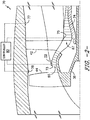
- the present disclosure is directed to an improved electrostatic sensor system 70 ( FIG. 2 ) and method 100 ( FIG. 7 ) for detecting dust and/or debris in the gas turbine engine 10, such as those described herein. More specifically, as shown in FIG. 2 , the sensor system 70 includes one or more electrostatic sensors 73, 75, 77, 78 communicatively coupled to a controller 90.
- FIGS. 3-5 illustrate various views of one of the electrostatic sensors 73 for illustrative purposes only.
- FIG. 3 illustrates a perspective view of the electrostatic sensor 73
- FIG. 4 illustrates a bottom view of the electrostatic sensor 73 as viewed from the sensing face 85
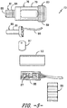
- FIG. 5 illustrates perspective views of the various components of the electrostatic sensor 73.
- the electrostatic sensor 73 defines an outer housing 76 or casing that includes a body 79 having a first end 81 and a second end 83. Further, as shown, the first end 81 of the sensor 73 defines a sensing face 85. In addition, the first end 81 is configured to be mounted or otherwise secured to the gas turbine engine 10.
- the body 79 of the outer housing 76 may have a predetermined shape configured to fit in an existing location of the gas turbine engine 10. More specifically, as shown in FIGS. 3-5 , the predetermined shape of the body 79 of the outer housing 76 may be a generally cylindrical shape. Thus, as shown in FIG.
- the existing location of the gas turbine engine 10 may include a borescope port (e.g. sensor 75) or a wash water port (e.g. sensor 78).
- the existing location of the gas turbine engine 10 may include a compressor inlet (e.g. sensor 75), a booster inlet (e.g. sensor 73), or a turbine inlet (not shown) of the gas turbine engine 10.
- the first end 81 of the outer housing 76 may include a first threaded outer surface 84 configured for securing the sensor 73 in a mounting location of the gas turbine engine 10. It should be understood that the outer housing 76 may further be adapted to fit in any suitable location of the gas turbine engine 10 where particulate detection is desired.
- the electrostatic sensor 73 includes an internal electrode 86 and amplifier 87 configured within the outer housing 76 adjacent to the sensing face 85. Further, the electrode 86 contains a plurality of electrons (not shown) configured to move within the electrode 86 as charged particles within the engine 10 flow past the sensing face 85. More specifically, the electrons are configured to move within the electrode 86 either towards or away from the sensing face 85 based on the charge of the passing particles.
- the sensor 73 may also include an electrode housing 91 configured within the outer housing 76 adjacent to the sensor face 85. As such, the electrode housing 91 is configured to house and protect the electrode 86.
- the amplifier 87 is configured to detect or measure the location of the electrons within the electrode 83 so as to indicate a particulate level of the charged particles flowing past the sensing face 79.
- the amplifier 87 is configured to detect a particulate level as a function of the electron movement.
- the integrated amplifier 87 of the present disclosure is extremely sensitive and capable of more accurately detecting particulate levels of the gas turbine engine 10. More specifically, in certain embodiments, the amplifier 87 may include a leakage current of from about 1 femtoampere to about 5 femtoampere, more preferably about 3 femtoampere. Thus, the low leakage current facilitates DC coupling of the amplifier 87, which allows low frequency changes in particulate levels to be captured. Further, the amplifier 87 may have an operating temperature range of from about 100 degrees Celsius (°C) to about 250°C, more preferably from about 150°C to about 230°C.
- the electrode 86 may have an impedance of greater than about 1 G-Ohm, for example about 10 G-Ohm.
- the high input impedance of the electrode 86 is configured to improve the sensor sensitivity to small changes in charge in the sensing face 85.
- the high input impedance is also configured to improve the low frequency response of the sensor 73 by preventing sensed electrons from leaking away such that an output signal cannot be produced.
- the electrostatic sensor(s) 73 of the present disclosure is capable of detecting from about one (1) part in seven (7) million by mass of particles.
- the electrostatic sensor(s) 73 is further configured to detect any/all airborne aerosol particulates including but not limited to ice crystals, construction debris, sand, and/or volcanic ash within the engine flowpath and alert the controller 90 in the event of such detection. Further, the electrostatic sensor(s) 73 is further configured to detect internally-generated dust and debris and alert the controller.
- the electrostatic sensor 73 also includes an integrated circuit board 88 configured within the outer housing 76 and electrically coupled to the amplifier 87. Further, as shown, the electrode 86 may be electrically coupled to the circuit board 88 via an insulated wire 98. More specifically, as shown, the circuit board 86 may be configured adjacent to the electrode 86 and opposite the sensing face 85. In additional embodiments, the circuit board 88 may be located at any suitable location within the outer housing 76 of the sensor 73. Further, the circuit board 88 as described herein may include any suitable circuit board that mechanically supports and electrically connects the electronic components of the sensor(s) 73.
- circuit boards of the present disclosure may include conductive tracks, pads, and/or other features etched from metal, such as copper, sheets that are laminated onto a non-conductive substrate.
- the circuit board 88 of the present disclosure may be single-sided, double-sided, or multi-layered.
- the circuit board 88 as described herein is configured to send one or more signals to the controller 90 of the gas turbine engine 10 that are indicative of the particulate level in the engine 10.
- the sensor 73 may include a circuit board housing 93 configured within the outer housing 76 adjacent to the electrode 86.
- the circuit board housing 93 may be configured to house and protect the circuit board 88 therein.
- the circuit board housing 93 may have any suitable shape.
- the circuit board housing 93 may have a shape that generally corresponds to an internal volume of the outer housing 76.
- the electrostatic sensor 73 may also include a sensor cap 99 configured with the second end 83 of the body 79 of the outer housing 76 so as to retain the sensor components, such as the electrode 86 and the amplifier 87, within the outer housing 76.
- the second end 83 of the body 79 may include a second threaded outer surface 89 configured to receive corresponding threads of an inner surface of the sensor cap 99.
- the sensor cap 99 may include both an inner threaded surface and/or an outer threaded surface.
- the electrostatic sensor(s) 73 may also include one or more insulators 97 or insulation layers.
- the electrostatic sensor(s) 73 may include an insulator 97 between the electrode 86 and the outer housing 76. More specifically, the insulator 97 may be configured with a rear-side of the electrode 86 and may include a hole such that the electrode wire 98 can pass therethrough. It should further be understood that any number of insulators may be employed at any suitable location within the sensor 73.
- the controller 90 is configured to receive the signals from the sensor(s) 73 from the circuit board 88 that are indicative of the particulate level in the engine 10. More specifically, as shown in FIG. 6 , there is illustrated a block diagram of one embodiment of suitable components that may be included in the controller 90 according to the present disclosure. As shown, the controller 90 may include one or more processor(s) 92 and associated memory device(s) 94 configured to perform a variety of computer-implemented functions (e.g., performing the methods, steps, calculations and the like and storing relevant data as disclosed herein). Additionally, the controller 90 may also include a communications module 95 to facilitate communications between the controller 90 and the electrostatic sensor(s) 73.
- a communications module 95 to facilitate communications between the controller 90 and the electrostatic sensor(s) 73.
- the communications module 95 may include a sensor interface 96 (e.g., one or more analog-to-digital converters) to permit signals transmitted from the sensor(s) 73 to be converted into signals that can be understood and processed by the processor(s) 92.
- the sensor(s) 73 may be communicatively coupled to the communications module 95 using any suitable means.
- the sensors 73 are coupled to the sensor interface 96 via a wired connection.
- the sensors 73 may be coupled to the sensor interface 96 via a wireless connection, such as by using any suitable wireless communications protocol known in the art.
- the processor(s) 92 may be configured to receive one or more signals from the sensors 73.
- the term "processor” refers not only to integrated circuits referred to in the art as being included in a computer, but also refers to a controller, a microcontroller, a microcomputer, a programmable logic controller (PLC), an application specific integrated circuit, and other programmable circuits.
- the memory device(s) 92 may generally include memory element(s) including, but not limited to, computer readable medium (e.g., random access memory (RAM)), computer readable non-volatile medium (e.g., a flash memory), cloud storage, a floppy disk, a compact disc-read only memory (CD-ROM), a magneto-optical disk (MOD), a digital versatile disc (DVD) and/or other suitable memory elements.
- Such memory device(s) 94 may generally be configured to store suitable computer-readable instructions that, when implemented by the processor(s) 92, configure the controller 90 to perform various functions of the gas turbine engine 10.
- the method 100 includes providing an integrated electrostatic sensor (e.g. sensor 73) in one or more locations of the gas turbine engine 10, such as those illustrated in FIG. 2 .
- the method 100 includes mounting the sensing face 85 of each sensor 73 in a particulate flow path at the one or more locations.
- the method 100 includes determining, via the amplifier 87 of each sensor 73, a particulate level of the gas turbine engine 10 as a function of the electron movement.
- the method 100 includes generating, via the circuit board 88 configured within the outer housing 76, one or more signals indicative of the particulate level.
- the method 100 may also include sending, via the circuit board 86 of the each of the electrostatic sensors 73, 75, the signal(s) to the controller 90 of the gas turbine engine 10.
- the sensors 73 described herein provide real-time, accurate particulate level data to a user.
Landscapes
- Chemical & Material Sciences (AREA)
- Physics & Mathematics (AREA)
- General Physics & Mathematics (AREA)
- General Health & Medical Sciences (AREA)
- Immunology (AREA)
- Life Sciences & Earth Sciences (AREA)
- Analytical Chemistry (AREA)
- Biochemistry (AREA)
- Pathology (AREA)
- Health & Medical Sciences (AREA)
- Dispersion Chemistry (AREA)
- Chemical Kinetics & Catalysis (AREA)
- Electrochemistry (AREA)
- Engineering & Computer Science (AREA)
- Combustion & Propulsion (AREA)
- Investigating Or Analyzing Materials By The Use Of Electric Means (AREA)
- Other Investigation Or Analysis Of Materials By Electrical Means (AREA)
- Testing Of Engines (AREA)
Abstract
Description
- The present subject matter relates generally to dust and debris sensors, and more particularly, to electrostatic dust and debris sensors for engines, such as gas turbine engines.
- A gas turbine engine generally includes, in serial flow order, a compressor section, a combustion section, a turbine section and an exhaust section. In operation, air enters an inlet of the compressor section where one or more axial or centrifugal compressors progressively compress the air until it reaches the combustion section. Fuel is mixed with the compressed air and burned within the combustion section to provide combustion gases. The combustion gases are routed from the combustion section through a hot gas path defined within the turbine section and then exhausted from the turbine section via the exhaust section.
- In particular configurations, the turbine section includes, in serial flow order, a high pressure (HP) turbine and a low pressure (LP) turbine. The HP turbine and the LP turbine each include various rotatable turbine components such as turbine rotor blades, rotor disks and retainers, and various stationary turbine components such as stator vanes or nozzles, turbine shrouds, and engine frames. The rotatable and stationary turbine components at least partially define the hot gas path through the turbine section. As the combustion gases flow through the hot gas path, thermal energy is transferred from the combustion gases to the rotatable and stationary turbine components.
- Such gas turbine engines are commonly employed in an aircraft. During operation of the aircraft, the engine environmental particulate and dust ingestion level is a key input to the analytics process, resulting in specific engine-by-engine action. Current particulate level data is provided by ground-based and/or remote sensing systems. Such data has temporal and special variations as well as error, thereby making accurate assessment of engine conditions at takeoff and climb of the aircraft particularly difficult. Further, the electronics of such sensor systems are typically connected to the individual sensors via a plurality of cables and connectors. Thus, any motion or vibration of the cabling can produce more charge than the dust or debris particles passing the sensor face, thereby resulting in a poor signal-to-noise ratio. Further, conventional systems can experience issues due to the triboelectric and piezoelectric effects of the cables and connectors.
- Accordingly, the present disclosure is directed to an improved sensor system that addresses the aforementioned issues. More specifically, the present disclosure is directed to a sensor system that includes one or more improved electrostatic sensors having integrated electronics that more accurately detects dust particles and/or debris within an engine such as the gas turbine engine described above.
- Various aspects and advantages of the invention will be set forth in part in the following description, or may be clear from the description, or may be learned through practice of the invention.
- In one aspect, the present disclosure is directed to an integrated electrostatic sensor for detecting dust and/or debris in an engine, such as an aircraft engine. The sensor includes an outer housing having a body with a first end and a second end. The first end is configured for securing the sensor to the engine and includes a sensing face. The sensor also includes an electrode configured within the housing adjacent to the sensing face and an amplifier configured with the electrode. The electrode contains a plurality of electrons configured to move as charged particles within the engine flow past the sensing face. Thus, the amplifier is configured to detect a particulate level of the engine as a function of the electron movement. The electrostatic sensor also includes a circuit board configured within the outer housing and electrically coupled to the amplifier. As such, the circuit board is configured to send one or more signals to a controller of the engine indicative of the particulate level.
- In another aspect, the present disclosure is directed to an electrostatic sensor system for an engine. The sensor system includes one or more integrated electrostatic sensors for detecting dust and/or debris in the engine. Each of the electrostatic sensors includes an outer housing having a body with a first end and a second end. The first end is configured for securing the sensor to the engine and includes a sensing face. Each sensor also includes an electrode configured within the outer housing adjacent to the sensing face and an amplifier configured with the electrode. The electrode contains a plurality of electrons configured to move as charged dust or debris particles within the engine flow past the sensing face. Thus, the amplifier is configured to detect a particulate level as a function of the electron movement. Each of the sensors also includes a circuit board configured within the outer housing and electrically coupled to the amplifier. Thus, the sensor system also includes a controller electrically coupled to the circuit board so as to receive one or more signals generated thereby that are indicative of the particulate level. It should be understood that the sensor system may be further configured with any of the additional features as described herein.
- In yet another aspect, the present disclosure is directed to a method for detecting dust or debris in an engine, e.g. in an aircraft engine. The method includes providing an integrated electrostatic sensor in one or more locations of the engine, with each of the electrostatic sensors including an outer housing having a first end and second end. The first end of the outer housing is configured for securing the sensor to the engine and includes a sensing face. Further, each of the electrostatic sensors includes an internal electrode and amplifier housed within the outer housing. The electrode is adjacent to the sensing face and has a plurality of electrons configured to move as charged particles within the engine flow past the sensing face. Thus, the method also includes mounting the sensing face of each sensor in a particulate flow path at the one or more locations. In addition, the method includes determining, via the amplifier of each sensor, a particulate level of the engine as a function of the electron movement. The method also includes generating, via a circuit board configured within the outer housing, one or more signals indicative of the particulate level. It should be understood that the method may further include any additional steps and/or features as described herein.
- Various features, aspects and advantages of the present invention will become better understood with reference to the following description and appended claims. The accompanying drawings, which are incorporated in and constitute a part of this specification, illustrate embodiments of the invention and, together with the description, serve to explain the principles of the invention.
- In the drawings:
-
FIG. 1 illustrates a schematic cross-sectional view of one embodiment of a gas turbine engine according to the present disclosure; -
FIG. 2 illustrates a schematic diagram of one embodiment of a sensor system for detecting dust or debris in an engine according to the present disclosure; -
FIG. 3 illustrates a perspective view of one embodiment of an electrostatic sensor for detecting dust or debris in an engine according to the present disclosure; -
FIG. 4 illustrates a bottom view of one embodiment of an electrostatic sensor for detecting dust or debris in an engine according to the present disclosure, particularly illustrating the sensing face of the sensor; -
FIG. 5 illustrates perspective views of the various components of the electrostatic sensor for detecting dust or debris in an engine according to the present disclosure; -
FIG. 6 illustrates a block diagram of one embodiment of suitable components that may be included in a controller of an engine according to the present disclosure; and -
FIG. 7 illustrates a flow diagram of one embodiment of method for detecting dust or debris in an engine according to the present disclosure. - Reference now will be made in detail to embodiments of the invention, one or more examples of which are illustrated in the drawings. Each example is provided by way of explanation of the invention, not limitation of the invention. In fact, it will be apparent to those skilled in the art that various modifications and variations can be made in the present invention without departing from the scope or spirit of the invention. For instance, features illustrated or described as part of one embodiment can be used with another embodiment to yield a still further embodiment. Thus, it is intended that the present invention covers such modifications and variations as come within the scope of the appended claims and their equivalents.
- As used herein, the terms "first", "second", and "third" may be used interchangeably to distinguish one component from another and are not intended to signify location or importance of the individual components.
- The terms "upstream" and "downstream" refer to the relative direction with respect to fluid flow in a fluid pathway. For example, "upstream" refers to the direction from which the fluid flows, and "downstream" refers to the direction to which the fluid flows.
- Generally, the present disclosure is directed to an electrostatic sensor system and methods for detecting dust, debris and/or other airborne particulates in an engine, e.g. an aircraft gas turbine engine. Further, it should be understood that the electrostatic sensor system and related methods are also suitable for any other type of engine, including but not limited to an industrial engine, a power generation engine, a land-based engine, a marine engine, or similar. More specifically, in certain embodiment, the electrostatic sensor system may include a controller electrically coupled with one or more electrostatic sensors. Each of the electrostatic sensors includes an outer housing having a first end configured for securing the sensor to the engine and having a sensing face. The sensor also includes an internal electrode configured within the outer housing adjacent to the sensing face and an amplifier configured with the electrode. The electrode contains a plurality of electrons configured to move as charged particles flow past the sensing face. Thus, the amplifier is configured to detect a particulate level as a function of electron movement. The electrostatic sensor also includes a circuit board configured within the outer housing and electrically coupled to the amplifier. Thus, the circuit board is configured to send the one or more signals to a controller of the engine indicative of the particulate level.
- Thus, the outer housing and electronics configuration minimize the distance between the sensor input and the electrode, thereby increasing sensitivity of the sensor. As such, the present disclosure provides various advantages not present in the prior art. For example, the electrostatic sensors of the present disclosure provide more accurate particulate (e.g. dust, debris, or similar) detection in engines that is robust and reliable. Further, since the electronics are integrated within the sensor, the present design requires less maintenance and suffers from fewer operational issues over prior art designs. Moreover, the amplifier low leakage current facilitates DC coupling of the amplifier, which allows low frequency changes in particulate levels to be captured. In addition, the high input impedance of the electrode improves the sensor sensitivity to small changes in charge in the sensing face. Further, the high input impedance of the electrode also improves the low frequency response of the sensor by preventing sensed electrons from leaking away such that an output signal cannot be produced. Thus, the electrostatic sensor of the present disclosure is capable of detecting from about one (1) part in seven (7) million by mass of particles. Moreover, electrostatic sensors of the present disclosure can provide ice detection, as well as volcanic ash and/or other damaging ingested particulate detection in addition to dust.
- Referring now to the drawings,
FIG. 1 illustrates a schematic cross-sectional view of one embodiment of a gas turbine engine 10 (high-bypass type) according to the present disclosure. More specifically, thegas turbine engine 10 may include an aircraft engine, e.g. for an airplane, helicopter, or similar. As shown, thegas turbine engine 10 has an axiallongitudinal centerline axis 12 therethrough for reference purposes. Further, as shown, thegas turbine engine 10 preferably includes a core gas turbine engine generally identified bynumeral 14 and afan section 16 positioned upstream thereof. Thecore engine 14 typically includes a generally tubularouter casing 18 that defines anannular inlet 20. Theouter casing 18 further encloses and supports abooster 22 for raising the pressure of the air that enterscore engine 14 to a first pressure level. A high pressure, multi-stage, axial-flow compressor 24 receives pressurized air from thebooster 22 and further increases the pressure of the air. Thecompressor 24 includes rotating blades and stationary vanes that have the function of directing and compressing air within theturbine engine 10. The pressurized air flows to acombustor 26, where fuel is injected into the pressurized air stream and ignited to raise the temperature and energy level of the pressurized air. The high energy combustion products flow from thecombustor 26 to a first (high pressure)turbine 28 for driving thehigh pressure compressor 24 through a first (high pressure) driveshaft 30, and then to a second (low pressure)turbine 32 for driving thebooster 22 and thefan section 16 through a second (low pressure) driveshaft 34 that is coaxial with thefirst drive shaft 30. After driving each of theturbines core engine 14 through anexhaust nozzle 36 to provide at least a portion of the jet propulsive thrust of theengine 10. - The
fan section 16 includes a rotatable, axial-flow fan rotor 38 that is surrounded by anannular fan casing 40. It will be appreciated thatfan casing 40 is supported from thecore engine 14 by a plurality of substantially radially-extending, circumferentially-spaced outlet guide vanes 42. In this way, thefan casing 40 encloses thefan rotor 38 and thefan rotor blades 44. Thedownstream section 46 of thefan casing 40 extends over an outer portion of thecore engine 14 to define a secondary, or bypass,airflow conduit 48 that provides additional jet propulsive thrust. - From a flow standpoint, it will be appreciated that an initial airflow, represented by
arrow 50, enters thegas turbine engine 10 through aninlet 52 to thefan casing 40. The airflow passes through thefan blades 44 and splits into a first air flow (represented by arrow 54) that moves through theconduit 48 and a second air flow (represented by arrow 56) which enters thebooster 22. - The pressure of the second
compressed airflow 56 is increased and enters thehigh pressure compressor 24, as represented byarrow 58. After mixing with fuel and being combusted in thecombustor 26, thecombustion products 60 exit thecombustor 26 and flow through thefirst turbine 28. Thecombustion products 60 then flow through thesecond turbine 32 and exit theexhaust nozzle 36 to provide at least a portion of the thrust for thegas turbine engine 10. - Still referring to
FIG. 1 , thecombustor 26 includes anannular combustion chamber 62 that is coaxial with thelongitudinal centerline axis 12, as well as aninlet 64 and anoutlet 66. As noted above, thecombustor 26 receives an annular stream of pressurized air from a high pressurecompressor discharge outlet 69. A portion of this compressor discharge air flows into a mixer (not shown). Fuel is injected from afuel nozzle 80 to mix with the air and form a fuel-air mixture that is provided to thecombustion chamber 62 for combustion. Ignition of the fuel-air mixture is accomplished by a suitable igniter, and the resultingcombustion gases 60 flow in an axial direction toward and into an annular, firststage turbine nozzle 72. Thenozzle 72 is defined by an annular flow channel that includes a plurality of radially-extending, circumferentially-spacednozzle vanes 74 that turn the gases so that they flow angularly and impinge upon the first stage turbine blades of thefirst turbine 28. As shown inFIG. 1 , thefirst turbine 28 preferably rotates the high-pressure compressor 24 via thefirst drive shaft 30, whereas the low-pressure turbine 32 preferably drives thebooster 22 and thefan rotor 38 via thesecond drive shaft 34. - The
combustion chamber 62 is housed within the engineouter casing 18 and fuel is supplied into thecombustion chamber 62 by one ormore fuel nozzles 80. More specifically, liquid fuel is transported through one or more passageways or conduits within a stem of thefuel nozzle 80. - During operation, dust and other types of aerosol particulates are ingested by the
gas turbine engine 10, e.g. from air entering theinlet 52. Dust and aerosol particulate accumulation is a key input for engine analytics as these levels are important in evaluating engine service time, wear and tear, and/or other maintenance schedules. Thus, the present disclosure is directed to an improved electrostatic sensor system 70 (FIG. 2 ) and method 100 (FIG. 7 ) for detecting dust and/or debris in thegas turbine engine 10, such as those described herein. More specifically, as shown inFIG. 2 , thesensor system 70 includes one or moreelectrostatic sensors controller 90. Each of theelectrostatic sensors FIGS. 3-5 illustrate various views of one of theelectrostatic sensors 73 for illustrative purposes only. For example,FIG. 3 illustrates a perspective view of theelectrostatic sensor 73;FIG. 4 illustrates a bottom view of theelectrostatic sensor 73 as viewed from thesensing face 85; andFIG. 5 illustrates perspective views of the various components of theelectrostatic sensor 73. - As shown in
FIGS. 3 and5 , theelectrostatic sensor 73 defines anouter housing 76 or casing that includes abody 79 having afirst end 81 and asecond end 83. Further, as shown, thefirst end 81 of thesensor 73 defines asensing face 85. In addition, thefirst end 81 is configured to be mounted or otherwise secured to thegas turbine engine 10. For example, in certain embodiments, thebody 79 of theouter housing 76 may have a predetermined shape configured to fit in an existing location of thegas turbine engine 10. More specifically, as shown inFIGS. 3-5 , the predetermined shape of thebody 79 of theouter housing 76 may be a generally cylindrical shape. Thus, as shown inFIG. 2 , the existing location of thegas turbine engine 10 may include a borescope port (e.g. sensor 75) or a wash water port (e.g. sensor 78). In additional embodiments, the existing location of thegas turbine engine 10 may include a compressor inlet (e.g. sensor 75), a booster inlet (e.g. sensor 73), or a turbine inlet (not shown) of thegas turbine engine 10. As such, in any of the embodiments described herein, thefirst end 81 of theouter housing 76 may include a first threadedouter surface 84 configured for securing thesensor 73 in a mounting location of thegas turbine engine 10. It should be understood that theouter housing 76 may further be adapted to fit in any suitable location of thegas turbine engine 10 where particulate detection is desired. - Referring particularly to
FIG. 5 , theelectrostatic sensor 73 includes aninternal electrode 86 andamplifier 87 configured within theouter housing 76 adjacent to thesensing face 85. Further, theelectrode 86 contains a plurality of electrons (not shown) configured to move within theelectrode 86 as charged particles within theengine 10 flow past thesensing face 85. More specifically, the electrons are configured to move within theelectrode 86 either towards or away from thesensing face 85 based on the charge of the passing particles. In certain embodiments, thesensor 73 may also include anelectrode housing 91 configured within theouter housing 76 adjacent to thesensor face 85. As such, theelectrode housing 91 is configured to house and protect theelectrode 86. Accordingly, theamplifier 87 is configured to detect or measure the location of the electrons within theelectrode 83 so as to indicate a particulate level of the charged particles flowing past thesensing face 79. Thus, theamplifier 87 is configured to detect a particulate level as a function of the electron movement. - As mentioned, the
integrated amplifier 87 of the present disclosure is extremely sensitive and capable of more accurately detecting particulate levels of thegas turbine engine 10. More specifically, in certain embodiments, theamplifier 87 may include a leakage current of from about 1 femtoampere to about 5 femtoampere, more preferably about 3 femtoampere. Thus, the low leakage current facilitates DC coupling of theamplifier 87, which allows low frequency changes in particulate levels to be captured. Further, theamplifier 87 may have an operating temperature range of from about 100 degrees Celsius (°C) to about 250°C, more preferably from about 150°C to about 230°C. Moreover, theelectrode 86 may have an impedance of greater than about 1 G-Ohm, for example about 10 G-Ohm. As such, the high input impedance of theelectrode 86 is configured to improve the sensor sensitivity to small changes in charge in thesensing face 85. In addition, the high input impedance is also configured to improve the low frequency response of thesensor 73 by preventing sensed electrons from leaking away such that an output signal cannot be produced. Thus, the electrostatic sensor(s) 73 of the present disclosure is capable of detecting from about one (1) part in seven (7) million by mass of particles. - In additional embodiments, the electrostatic sensor(s) 73 is further configured to detect any/all airborne aerosol particulates including but not limited to ice crystals, construction debris, sand, and/or volcanic ash within the engine flowpath and alert the
controller 90 in the event of such detection. Further, the electrostatic sensor(s) 73 is further configured to detect internally-generated dust and debris and alert the controller. - Referring particularly to
FIG. 5 , theelectrostatic sensor 73 also includes an integratedcircuit board 88 configured within theouter housing 76 and electrically coupled to theamplifier 87. Further, as shown, theelectrode 86 may be electrically coupled to thecircuit board 88 via aninsulated wire 98. More specifically, as shown, thecircuit board 86 may be configured adjacent to theelectrode 86 and opposite thesensing face 85. In additional embodiments, thecircuit board 88 may be located at any suitable location within theouter housing 76 of thesensor 73. Further, thecircuit board 88 as described herein may include any suitable circuit board that mechanically supports and electrically connects the electronic components of the sensor(s) 73. More specifically, certain circuit boards of the present disclosure may include conductive tracks, pads, and/or other features etched from metal, such as copper, sheets that are laminated onto a non-conductive substrate. Further, thecircuit board 88 of the present disclosure may be single-sided, double-sided, or multi-layered. Thus, thecircuit board 88 as described herein is configured to send one or more signals to thecontroller 90 of thegas turbine engine 10 that are indicative of the particulate level in theengine 10. - Further, as shown in
FIG. 5 , thesensor 73 may include acircuit board housing 93 configured within theouter housing 76 adjacent to theelectrode 86. Thus, thecircuit board housing 93 may be configured to house and protect thecircuit board 88 therein. Thecircuit board housing 93 may have any suitable shape. For example, in one embodiment, thecircuit board housing 93 may have a shape that generally corresponds to an internal volume of theouter housing 76. - In additional embodiments, as shown in
FIGS. 3-5 , theelectrostatic sensor 73 may also include asensor cap 99 configured with thesecond end 83 of thebody 79 of theouter housing 76 so as to retain the sensor components, such as theelectrode 86 and theamplifier 87, within theouter housing 76. More specifically, as shown, thesecond end 83 of thebody 79 may include a second threadedouter surface 89 configured to receive corresponding threads of an inner surface of thesensor cap 99. In particular embodiments, as shown, thesensor cap 99 may include both an inner threaded surface and/or an outer threaded surface. - Referring still to
FIG. 5 , the electrostatic sensor(s) 73 may also include one ormore insulators 97 or insulation layers. For example, as shown inFIG. 5 , the electrostatic sensor(s) 73 may include aninsulator 97 between theelectrode 86 and theouter housing 76. More specifically, theinsulator 97 may be configured with a rear-side of theelectrode 86 and may include a hole such that theelectrode wire 98 can pass therethrough. It should further be understood that any number of insulators may be employed at any suitable location within thesensor 73. - Referring now to
FIGS. 2 and6 , thecontroller 90 is configured to receive the signals from the sensor(s) 73 from thecircuit board 88 that are indicative of the particulate level in theengine 10. More specifically, as shown inFIG. 6 , there is illustrated a block diagram of one embodiment of suitable components that may be included in thecontroller 90 according to the present disclosure. As shown, thecontroller 90 may include one or more processor(s) 92 and associated memory device(s) 94 configured to perform a variety of computer-implemented functions (e.g., performing the methods, steps, calculations and the like and storing relevant data as disclosed herein). Additionally, thecontroller 90 may also include acommunications module 95 to facilitate communications between thecontroller 90 and the electrostatic sensor(s) 73. Further, thecommunications module 95 may include a sensor interface 96 (e.g., one or more analog-to-digital converters) to permit signals transmitted from the sensor(s) 73 to be converted into signals that can be understood and processed by the processor(s) 92. It should be appreciated that the sensor(s) 73 may be communicatively coupled to thecommunications module 95 using any suitable means. For example, as shown inFIG. 6 , thesensors 73 are coupled to thesensor interface 96 via a wired connection. However, in other embodiments, thesensors 73 may be coupled to thesensor interface 96 via a wireless connection, such as by using any suitable wireless communications protocol known in the art. As such, the processor(s) 92 may be configured to receive one or more signals from thesensors 73. - As used herein, the term "processor" refers not only to integrated circuits referred to in the art as being included in a computer, but also refers to a controller, a microcontroller, a microcomputer, a programmable logic controller (PLC), an application specific integrated circuit, and other programmable circuits. Additionally, the memory device(s) 92 may generally include memory element(s) including, but not limited to, computer readable medium (e.g., random access memory (RAM)), computer readable non-volatile medium (e.g., a flash memory), cloud storage, a floppy disk, a compact disc-read only memory (CD-ROM), a magneto-optical disk (MOD), a digital versatile disc (DVD) and/or other suitable memory elements. Such memory device(s) 94 may generally be configured to store suitable computer-readable instructions that, when implemented by the processor(s) 92, configure the
controller 90 to perform various functions of thegas turbine engine 10. - Referring now to
FIG. 7 , a flow diagram of one embodiment of amethod 100 for detecting dust or debris in agas turbine engine 10, e.g. an aircraft engine, is illustrated. As shown at 102, themethod 100 includes providing an integrated electrostatic sensor (e.g. sensor 73) in one or more locations of thegas turbine engine 10, such as those illustrated inFIG. 2 . Thus, as shown at 104, themethod 100 includes mounting thesensing face 85 of eachsensor 73 in a particulate flow path at the one or more locations. In addition, as shown at 106, themethod 100 includes determining, via theamplifier 87 of eachsensor 73, a particulate level of thegas turbine engine 10 as a function of the electron movement. As shown at 108, themethod 100 includes generating, via thecircuit board 88 configured within theouter housing 76, one or more signals indicative of the particulate level. - In one embodiment, the
method 100 may also include sending, via thecircuit board 86 of the each of theelectrostatic sensors controller 90 of thegas turbine engine 10. As such, thesensors 73 described herein provide real-time, accurate particulate level data to a user. - This written description uses examples to disclose the invention, including the preferred mode, and also to enable any person skilled in the art to practice the invention, including making and using any devices or systems and performing any incorporated methods. The patentable scope of the invention is defined by the claims, and may include other examples that occur to those skilled in the art. Such other examples are intended to be within the scope of the claims if they include structural elements that do not differ from the literal language of the claims, or if they include equivalent structural elements with insubstantial differences from the literal languages of the claims.
- Various aspects and embodiments of the present invention are defined by the following numbered clauses:
- 1. An integrated electrostatic sensor for detecting dust or debris in an engine, the sensor comprising:
- an outer housing comprising a body having a first end and a second end, the first end comprising a sensing face and configured for securing the sensor to the engine;
- an electrode configured within the outer housing adjacent to the sensing face, the electrode comprising a plurality of electrons configured to move as charged particles within the engine flow past the sensing face;
- an amplifier configured with the electrode, the amplifier configured to detect a particulate level of the engine as a function of the electron movement; and
- a circuit board configured within the outer housing and electrically coupled to the amplifier, the circuit board configured to send one or more signals to a controller of the engine indicative of the particulate level.
- 2. The sensor of clause 1, wherein the first end comprises a first threaded outer surface configured for securing the sensor in a mounting location of the engine.
- 3. The sensor of any preceding clause, wherein the body of the outer housing comprises a predetermined shape configured to fit in an existing location of the engine.
- 4. The sensor of any preceding clause, wherein the existing location comprises at least one of a borescope port, a wash water port, a compressor inlet, a booster inlet, or a turbine inlet of the engine.
- 5. The sensor of any preceding clause, wherein the predetermined shape of the body of the outer housing comprises a generally cylindrical shape.
- 6. The sensor of any preceding clause, wherein the amplifier comprises a leakage current of from about 1 femtoampere to about 5 femtoampere and an operating temperature range of from about 100 degrees Celsius to about 250 degrees Celsius.
- 7. The sensor of any preceding clause, wherein the electrode comprises an impedance of greater than about 1 G-Ohm.
- 8. The sensor of any preceding clause, further comprising a sensor cap configured with the second end of the body of the outer housing so as to retain the electrode and the amplifier within the outer housing.
- 9. The sensor of any preceding clause, wherein the second end comprises a second threaded outer surface configured to receive the sensor cap, the sensor cap comprising at least one of an inner threaded surface or an outer threaded surface.
- 10. The sensor of any preceding clause, further comprising an electrode housing configured within the outer housing adjacent to the sensor face, the electrode housing configured to house the electrode, the electrode electrically coupled to the circuit board via an insulated wire.
- 11. The sensor of any preceding clause, further comprising a circuit board housing configured within the outer housing adjacent to the electrode, the circuit board housing configured to house the circuit board therein.
- 12. The sensor of any preceding clause, further comprising an insulator configured between the electrode and the outer housing.
- 13. The sensor of any preceding clause, wherein the engine comprises at least one of an aircraft engine, an industrial engine, a power generation engine, a land-based engine, or a marine engine.
- 14. An electrostatic sensor system for an engine, the sensor system comprising:
- one or more integrated electrostatic sensors for detecting dust or debris in the engine, each of the electrostatic sensors comprising:
- an outer housing comprising a body having a first end and a second end, the first end comprising a sensing face and configured for securing the sensor to the engine,
- an electrode configured within the outer housing adjacent to the sensing face, the electrode comprising a plurality of electrons configured to move as charged particles within the engine flow past the sensing face,
- an amplifier configured with the electrode, the amplifier configured to detect a particulate level of the engine as a function of the electron movement, and
- a circuit board configured within the outer housing and electrically coupled to the amplifier; and
- a controller electrically coupled to the circuit board so as to receive one or more signals therefrom that are indicative of the particulate level.
- one or more integrated electrostatic sensors for detecting dust or debris in the engine, each of the electrostatic sensors comprising:
- 15. The sensor system of any preceding clause, wherein the first end comprises a first threaded outer surface configured for securing the sensor in a mounting location of the engine.
- 16. The sensor system of any preceding clause, wherein the body of the outer housing comprises a predetermined shape configured to fit in an existing location of the engine, wherein the predetermined shape of the body of the outer housing comprises a generally cylindrical shape, wherein the existing location comprises at least one of a borescope port, a wash water port, a compressor inlet, a booster inlet, or a turbine inlet of the engine.
- 17. The sensor system of any preceding clause, further comprising:
- an electrode housing configured within the outer housing adjacent to the sensor face, the electrode housing configured to house the electrode, the electrode electrically coupled to the circuit board via an insulated wire, and
- a circuit board housing configured within the outer housing adjacent to the electrode, the circuit board housing configured to house the circuit board therein.
- 18. The sensor system of any preceding clause, wherein the amplifier comprises a leakage current of from about 1 femtoampere to about 5 femtoampere and an operating temperature range of from about 100 degrees Celsius to about 250 degrees Celsius, and the electrode comprises an impedance of greater than about 1 G-Ohm.
- 19. A method for detecting dust or debris in an engine, the method comprising:
- providing an integrated electrostatic sensor in one or more locations of the engine, each of the electrostatic sensors including an outer housing with a first end having a sensing face, the first end configured for securing the sensor to the engine, each of the electrostatic sensors also having an internal electrode and amplifier housed within the outer housing, the electrode adjacent to the sensing face and having a plurality of electrons configured to move as charged particles within the engine flow past the sensing face;
- mounting the sensing face of each sensor in a particulate flow path at the one or more locations;
- determining, via the amplifier of each sensor, a particulate level of the engine as a function of the electron movement; and
- generating, via a circuit board configured within the outer housing, one or more signals indicative of the particulate level.
- 20. The method of any preceding clause, further comprising sending, via circuit board of the each of the electrostatic sensors, the one or more signals to a controller of the engine.
Claims (14)
- An integrated electrostatic sensor (75, 77, 78) for detecting dust or debris in a gas turbine engine (10), the sensor (75, 77, 78) comprising:an outer housing (76) comprising a body (79) having a first end (81) and a second end (83), the first end (81) comprising a sensing face (85) and configured for securing the sensor (75, 77, 78) to the gas turbine engine (10);an electrode (86) configured within the outer housing (76) adjacent to the sensing face (85), the electrode (86) comprising a plurality of electrons configured to move as charged particles within the gas turbine engine (10) flow past the sensing face (85);an amplifier (87) configured with the electrode (86), the amplifier (87) configured to detect a particulate level of the gas turbine engine (10) as a function of the electron movement; anda circuit board (88) configured within the outer housing (76) and electrically coupled to the amplifier (87), the circuit board (88) configured to send one or more signals to a controller (90) of the gas turbine engine (10) indicative of the particulate level.
- The sensor (75, 77, 78) of claim 1, wherein the first end (81) comprises a first threaded outer surface (84) configured for securing the sensor (75, 77, 78) in a mounting location of the gas turbine engine (10).
- The sensor (75, 77, 78) of any preceding claim, wherein the body (79) of the outer housing (76) comprises a predetermined shape configured to fit in an existing location of the gas turbine engine (10).
- The sensor (75, 77, 78) of claim 3, wherein the existing location comprises at least one of a borescope port, a wash water port, a compressor inlet, a booster inlet, or a turbine inlet of the gas turbine engine (10).
- The sensor (75, 77, 78) of claim 3 or claim 4, wherein the predetermined shape of the body (79) of the outer housing (76) comprises a generally cylindrical shape.
- The sensor (75, 77, 78) of any preceding claim, wherein the amplifier (87) comprises a leakage current of from about 1 femtoampere to about 5 femtoampere and an operating temperature range of from about 100 degrees Celsius to about 250 degrees Celsius.
- The sensor (75, 77, 78) of any preceding claim, wherein the electrode (86) comprises an impedance of greater than about 1 G-Ohm.
- The sensor (75, 77, 78) of any preceding claim, further comprising a sensor (75, 77, 78) cap configured with the second end (83) of the body (79) of the outer housing (76) so as to retain the electrode (86) and the amplifier (87) within the outer housing (76).
- The sensor (75, 77, 78) of claim 8, wherein the second end (83) comprises a second threaded outer surface (89) configured to receive the sensor (75, 77, 78) cap, the sensor (75, 77, 78) cap comprising at least one of an inner threaded surface or an outer threaded surface.
- The sensor (75, 77, 78) of any preceding claim, further comprising an electrode (86) housing configured within the outer housing (76) adjacent to the sensor (75, 77, 78) face, the electrode (86) housing configured to house the electrode (86), the electrode (86) electrically coupled to the circuit board (88) via an insulated wire.
- The sensor (75, 77, 78) of any preceding claim, further comprising a circuit board (88) housing configured within the outer housing (76) adjacent to the electrode (86), the circuit board (88) housing configured to house the circuit board (88) therein.
- The sensor (75, 77, 78) of any preceding claim, further comprising an insulator configured between the electrode (86) and the outer housing (76).
- The sensor (75, 77, 78) of any preceding claim, wherein the gas turbine engine (10) comprises an aircraft engine.
- An electrostatic sensor (75, 77, 78) system for a gas turbine engine (10), the sensor (75, 77, 78) system comprising:one or more integrated electrostatic sensor (75, 77, 78)s for detecting dust or debris in the gas turbine engine (10), each of the electrostatic sensor (75, 77, 78)s comprising:an outer housing (76) comprising a body (79) having a first end (81) and a second end (83), the first end (81) comprising a sensing face (85) and configured for securing the sensor (75, 77, 78) to the gas turbine engine (10),an electrode (86) configured within the outer housing (76) adjacent to the sensing face (85), the electrode (86) comprising a plurality of electrons configured to move as charged particles within the gas turbine engine (10) flow past the sensing face (85),an amplifier (87) configured with the electrode (86), the amplifier (87) configured to detect a particulate level of the gas turbine engine (10) as a function of the electron movement, anda circuit board (88) configured within the outer housing (76) and electrically coupled to the amplifier (87); anda controller (90) electrically coupled to the circuit board (88) so as to receive one or more signals therefrom that are indicative of the particulate level.
Applications Claiming Priority (1)
| Application Number | Priority Date | Filing Date | Title |
|---|---|---|---|
| US15/007,289 US9714967B1 (en) | 2016-01-27 | 2016-01-27 | Electrostatic dust and debris sensor for an engine |
Publications (2)
| Publication Number | Publication Date |
|---|---|
| EP3199939A1 true EP3199939A1 (en) | 2017-08-02 |
| EP3199939B1 EP3199939B1 (en) | 2022-03-02 |
Family
ID=57794205
Family Applications (1)
| Application Number | Title | Priority Date | Filing Date |
|---|---|---|---|
| EP17151253.6A Active EP3199939B1 (en) | 2016-01-27 | 2017-01-12 | Electrostatic dust and debris sensor for an engine |
Country Status (5)
| Country | Link |
|---|---|
| US (1) | US9714967B1 (en) |
| EP (1) | EP3199939B1 (en) |
| JP (1) | JP6397515B2 (en) |
| CN (1) | CN107036944B (en) |
| CA (1) | CA2955527C (en) |
Families Citing this family (10)
| Publication number | Priority date | Publication date | Assignee | Title |
|---|---|---|---|---|
| US10073008B2 (en) | 2016-01-27 | 2018-09-11 | General Electric Company | Electrostatic sensor |
| US11149583B2 (en) * | 2017-04-18 | 2021-10-19 | Honeywell International Inc. | Gas turbine engine particulate ingestion and accumulation sensor system and method |
| US10359350B1 (en) * | 2018-01-23 | 2019-07-23 | Hai Lin | Method and system for particle characterization in harsh environments |
| US10768059B2 (en) * | 2018-02-16 | 2020-09-08 | Raytheon Technologies Corporation | Embedded optical probe for gas turbine engine |
| US11153960B1 (en) | 2018-06-08 | 2021-10-19 | Innoveering, LLC | Plasma-based electro-optical sensing and methods |
| US10996140B2 (en) | 2019-03-08 | 2021-05-04 | Rolls-Royce Corporation | Gas turbine engine probes and methods of detecting an engine condition |
| CN113552424A (en) * | 2021-06-29 | 2021-10-26 | 中国人民解放军火箭军工程大学 | Weak static signal collection system of aeroengine gas circuit granule |
| US12135549B2 (en) | 2022-02-10 | 2024-11-05 | General Electric Company | Systems and methods for providing information regarding particulate matter within an aircraft engine |
| US11946421B2 (en) | 2022-02-10 | 2024-04-02 | General Electric Company | Use of particulate sensor in engine power assurance |
| US12416546B2 (en) | 2023-06-05 | 2025-09-16 | General Electric Company | Slurry-based dust injection system |
Citations (4)
| Publication number | Priority date | Publication date | Assignee | Title |
|---|---|---|---|---|
| WO1984004390A1 (en) * | 1983-05-02 | 1984-11-08 | Battelle Development Corp | Apparatus and method for measuring the concentration of particles in a gas |
| EP2538199A2 (en) * | 2011-06-24 | 2012-12-26 | United Technologies Corporation | Signal processing for inlet debris monitoring system to distinguish particulates |
| EP2551660A2 (en) * | 2011-07-29 | 2013-01-30 | United Technologies Corporation | Aircraft debris monitoring sensor assembly |
| WO2015189593A1 (en) * | 2014-06-10 | 2015-12-17 | Cambridge Enterprise Limited | Sensing methods and apparatus |
Family Cites Families (42)
| Publication number | Priority date | Publication date | Assignee | Title |
|---|---|---|---|---|
| US3917432A (en) | 1974-11-13 | 1975-11-04 | Gen Electric | Borescope support apparatus |
| US4249131A (en) | 1979-04-11 | 1981-02-03 | The United States Of America As Represented By The Secretary Of Commerce | Method and apparatus for measuring electrostatic charge density |
| US4531402A (en) | 1983-05-02 | 1985-07-30 | Battelle Development Corp. | Apparatus and method for measuring the concentration of large particles in a gas |
| GB8707187D0 (en) | 1987-03-25 | 1987-04-29 | Hughes Ltd Stewart | Monitoring of foreign object in engines |
| JPH0754876Y2 (en) * | 1989-04-10 | 1995-12-18 | 株式会社東芝 | Charged particle detector |
| SG46261A1 (en) | 1990-04-09 | 1998-02-20 | Commw Scient Ind Res Org | A detection system for use in an aircraft |
| US5070722A (en) | 1990-09-21 | 1991-12-10 | United Technologies Corporation | Turbine engine debris ingestion monitor |
| GB2335745B (en) | 1998-03-27 | 2003-04-09 | Pcme Ltd | Improvements in and relating to particle detectors |
| US6668655B2 (en) | 2001-09-27 | 2003-12-30 | Siemens Westinghouse Power Corporation | Acoustic monitoring of foreign objects in combustion turbines during operation |
| FI118278B (en) * | 2003-06-24 | 2007-09-14 | Dekati Oy | Method and sensor device for measuring particulate emissions from combustion engine exhaust |
| US7275415B2 (en) | 2003-12-31 | 2007-10-02 | Honeywell International Inc. | Particulate-based flow sensor |
| US7230431B2 (en) * | 2004-01-27 | 2007-06-12 | Aadu Mirme | Integrating electrometer amplifying circuit |
| DE102004038422B3 (en) | 2004-07-30 | 2006-01-12 | Schefenacker Vision Systems Germany Gmbh | Sensor device, use of a sensor device and vehicle light |
| US7419532B2 (en) | 2004-10-05 | 2008-09-02 | Caterpillar Inc. | Deposition system and method |
| US7628007B2 (en) * | 2005-12-21 | 2009-12-08 | Honeywell International Inc. | Onboard diagnostics for anomalous cylinder behavior |
| US9163955B2 (en) | 2012-04-25 | 2015-10-20 | Eastman Kodak Company | Electronic sensing system with environmental sensor patches |
| GB2447238B (en) | 2007-03-07 | 2009-11-18 | Rolls Royce Plc | Method for detecting ice ingestion in a gas turbine engine |
| US8424279B2 (en) | 2007-03-28 | 2013-04-23 | United Technologies Corporation | Particle separator and debris control system |
| CN101275025A (en) * | 2007-03-30 | 2008-10-01 | 上海群康沥青科技有限公司 | Modified bituminous composition |
| US7696890B2 (en) | 2007-08-13 | 2010-04-13 | International Business Machines Corporation | Capacitive detection of dust accumulation using microcontroller component leads |
| WO2009140677A2 (en) | 2008-05-16 | 2009-11-19 | Honeywell International Inc. | Particulate matter sensor |
| US8074498B2 (en) | 2009-05-18 | 2011-12-13 | United Technologies Corporation | System and method of assessing thermal energy levels of a gas turbine engine component |
| US20100287907A1 (en) | 2009-05-18 | 2010-11-18 | Agrawal Rajendra K | System and method of estimating a gas turbine engine surge margin |
| US8204671B2 (en) | 2009-05-18 | 2012-06-19 | United Technologies Corporation | System and method of estimating gas turbine engine performance |
| US8256277B2 (en) | 2009-06-11 | 2012-09-04 | United Technologies Corporation | Gas turbine engine debris monitoring arrangement |
| US8448511B2 (en) * | 2009-09-02 | 2013-05-28 | Ford Global Technologies, Llc | Method for evaluating degradation of a particulate matter sensor after an engine start |
| US8310249B2 (en) | 2009-09-17 | 2012-11-13 | Woodward, Inc. | Surface gap soot sensor for exhaust |
| GB0917319D0 (en) | 2009-10-05 | 2009-11-18 | Rolls Royce Plc | An apparatus and method of operating a gas turbine engine |
| JP5438538B2 (en) * | 2010-02-08 | 2014-03-12 | 日本碍子株式会社 | Apparatus with abnormality determination function and abnormality determination method |
| GB2482480A (en) | 2010-08-02 | 2012-02-08 | Lockheed Martin Uk Insys Ltd | An electrostatic particle ingress inhibitor |
| JP4979798B2 (en) * | 2010-08-25 | 2012-07-18 | シャープ株式会社 | Ion detection device, air conditioner and ion measuring instrument |
| US8471730B2 (en) | 2010-09-16 | 2013-06-25 | The Boeing Company | Systems and methods for early detection of aircraft approach to volcanic plume |
| GB201016222D0 (en) | 2010-09-27 | 2010-11-10 | Natural Enviromental Res Council | Aerosol detection |
| US20130058419A1 (en) | 2011-09-05 | 2013-03-07 | Zhou Ye | Wireless video/audio data transmission system |
| US8761490B2 (en) | 2011-11-03 | 2014-06-24 | United Technologies Corporation | System and method for automated borescope inspection user interface |
| GB2496903B (en) | 2011-11-28 | 2015-04-15 | Rolls Royce Plc | An apparatus and a method of inspecting a turbomachine |
| US8950239B2 (en) | 2012-01-17 | 2015-02-10 | International Business Machines Corporation | Conductive dust detection |
| US8869603B2 (en) | 2012-02-29 | 2014-10-28 | United Technologies Corporation | Debris detection in turbomachinery and gas turbine engines |
| GB201219488D0 (en) * | 2012-10-30 | 2012-12-12 | Univ Sussex | Apparatus for sensing ionic current and ionising radiation |
| US9448154B2 (en) | 2013-05-10 | 2016-09-20 | The Boeing Company | Systems and methods for testing ignition properties of particles |
| US9074868B2 (en) | 2013-05-13 | 2015-07-07 | General Electric Company | Automated borescope measurement tip accuracy test |
| EP3041743B1 (en) | 2013-09-06 | 2020-01-01 | GE Aviation Systems LLC | Aircraft and particulate detection method |
-
2016
- 2016-01-27 US US15/007,289 patent/US9714967B1/en active Active
-
2017
- 2017-01-12 EP EP17151253.6A patent/EP3199939B1/en active Active
- 2017-01-19 CA CA2955527A patent/CA2955527C/en active Active
- 2017-01-20 JP JP2017008018A patent/JP6397515B2/en active Active
- 2017-01-25 CN CN201710056308.1A patent/CN107036944B/en active Active
Patent Citations (4)
| Publication number | Priority date | Publication date | Assignee | Title |
|---|---|---|---|---|
| WO1984004390A1 (en) * | 1983-05-02 | 1984-11-08 | Battelle Development Corp | Apparatus and method for measuring the concentration of particles in a gas |
| EP2538199A2 (en) * | 2011-06-24 | 2012-12-26 | United Technologies Corporation | Signal processing for inlet debris monitoring system to distinguish particulates |
| EP2551660A2 (en) * | 2011-07-29 | 2013-01-30 | United Technologies Corporation | Aircraft debris monitoring sensor assembly |
| WO2015189593A1 (en) * | 2014-06-10 | 2015-12-17 | Cambridge Enterprise Limited | Sensing methods and apparatus |
Also Published As
| Publication number | Publication date |
|---|---|
| US9714967B1 (en) | 2017-07-25 |
| CA2955527C (en) | 2019-06-11 |
| CN107036944A (en) | 2017-08-11 |
| JP2017133505A (en) | 2017-08-03 |
| JP6397515B2 (en) | 2018-09-26 |
| CA2955527A1 (en) | 2017-07-27 |
| CN107036944B (en) | 2020-05-19 |
| US20170212080A1 (en) | 2017-07-27 |
| EP3199939B1 (en) | 2022-03-02 |
Similar Documents
| Publication | Publication Date | Title |
|---|---|---|
| CA2955527C (en) | Electrostatic dust and debris sensor for an engine | |
| EP3199938B1 (en) | Electrostatic dust sensor for an engine | |
| US11156455B2 (en) | System and method for measuring clearance gaps between rotating and stationary components of a turbomachine | |
| CN104471194B (en) | By minimized for the gap between rotor and casing method | |
| US10996140B2 (en) | Gas turbine engine probes and methods of detecting an engine condition | |
| US10480345B2 (en) | Wear indication sensor designs and methods of integration | |
| EP4001894B1 (en) | Electrostatic particle sensor | |
| US20100158670A1 (en) | Combustor rumble | |
| EP2339706A1 (en) | Apparatus and assembly for a spark plug | |
| CN115163201A (en) | An apparatus and system for testing a high-pressure turbine rotor of an aero-engine | |
| US7269954B2 (en) | Method for operating a gas turbine installation, and gas turbine installation | |
| RU2258923C1 (en) | Method of diagnosing gas turbine engines at steady and non-steady states of operation | |
| US11041404B2 (en) | In-situ wireless monitoring of engine bearings | |
| Cartwright et al. | Marine gas turbine condition monitoring by gas path electrostatic detection techniques | |
| US12331648B2 (en) | Detecting engine exhaust debris using saturation current |
Legal Events
| Date | Code | Title | Description |
|---|---|---|---|
| PUAI | Public reference made under article 153(3) epc to a published international application that has entered the european phase |
Free format text: ORIGINAL CODE: 0009012 |
|
| STAA | Information on the status of an ep patent application or granted ep patent |
Free format text: STATUS: THE APPLICATION HAS BEEN PUBLISHED |
|
| AK | Designated contracting states |
Kind code of ref document: A1 Designated state(s): AL AT BE BG CH CY CZ DE DK EE ES FI FR GB GR HR HU IE IS IT LI LT LU LV MC MK MT NL NO PL PT RO RS SE SI SK SM TR |
|
| AX | Request for extension of the european patent |
Extension state: BA ME |
|
| STAA | Information on the status of an ep patent application or granted ep patent |
Free format text: STATUS: REQUEST FOR EXAMINATION WAS MADE |
|
| 17P | Request for examination filed |
Effective date: 20180202 |
|
| RBV | Designated contracting states (corrected) |
Designated state(s): AL AT BE BG CH CY CZ DE DK EE ES FI FR GB GR HR HU IE IS IT LI LT LU LV MC MK MT NL NO PL PT RO RS SE SI SK SM TR |
|
| GRAP | Despatch of communication of intention to grant a patent |
Free format text: ORIGINAL CODE: EPIDOSNIGR1 |
|
| STAA | Information on the status of an ep patent application or granted ep patent |
Free format text: STATUS: GRANT OF PATENT IS INTENDED |
|
| INTG | Intention to grant announced |
Effective date: 20210803 |
|
| RIN1 | Information on inventor provided before grant (corrected) |
Inventor name: WEICKERT, JOHN DAVID Inventor name: GRIFFIN, GREGORY Inventor name: NOEL, JAMES R. Inventor name: RICKARDS, CHARLES |
|
| GRAS | Grant fee paid |
Free format text: ORIGINAL CODE: EPIDOSNIGR3 |
|
| GRAA | (expected) grant |
Free format text: ORIGINAL CODE: 0009210 |
|
| STAA | Information on the status of an ep patent application or granted ep patent |
Free format text: STATUS: THE PATENT HAS BEEN GRANTED |
|
| AK | Designated contracting states |
Kind code of ref document: B1 Designated state(s): AL AT BE BG CH CY CZ DE DK EE ES FI FR GB GR HR HU IE IS IT LI LT LU LV MC MK MT NL NO PL PT RO RS SE SI SK SM TR |
|
| REG | Reference to a national code |
Ref country code: GB Ref legal event code: FG4D |
|
| REG | Reference to a national code |
Ref country code: CH Ref legal event code: EP Ref country code: AT Ref legal event code: REF Ref document number: 1472636 Country of ref document: AT Kind code of ref document: T Effective date: 20220315 |
|
| REG | Reference to a national code |
Ref country code: DE Ref legal event code: R096 Ref document number: 602017053925 Country of ref document: DE |
|
| REG | Reference to a national code |
Ref country code: IE Ref legal event code: FG4D |
|
| REG | Reference to a national code |
Ref country code: LT Ref legal event code: MG9D |
|
| REG | Reference to a national code |
Ref country code: NL Ref legal event code: MP Effective date: 20220302 |
|
| PG25 | Lapsed in a contracting state [announced via postgrant information from national office to epo] |
Ref country code: SE Free format text: LAPSE BECAUSE OF FAILURE TO SUBMIT A TRANSLATION OF THE DESCRIPTION OR TO PAY THE FEE WITHIN THE PRESCRIBED TIME-LIMIT Effective date: 20220302 Ref country code: RS Free format text: LAPSE BECAUSE OF FAILURE TO SUBMIT A TRANSLATION OF THE DESCRIPTION OR TO PAY THE FEE WITHIN THE PRESCRIBED TIME-LIMIT Effective date: 20220302 Ref country code: NO Free format text: LAPSE BECAUSE OF FAILURE TO SUBMIT A TRANSLATION OF THE DESCRIPTION OR TO PAY THE FEE WITHIN THE PRESCRIBED TIME-LIMIT Effective date: 20220602 Ref country code: LT Free format text: LAPSE BECAUSE OF FAILURE TO SUBMIT A TRANSLATION OF THE DESCRIPTION OR TO PAY THE FEE WITHIN THE PRESCRIBED TIME-LIMIT Effective date: 20220302 Ref country code: HR Free format text: LAPSE BECAUSE OF FAILURE TO SUBMIT A TRANSLATION OF THE DESCRIPTION OR TO PAY THE FEE WITHIN THE PRESCRIBED TIME-LIMIT Effective date: 20220302 Ref country code: ES Free format text: LAPSE BECAUSE OF FAILURE TO SUBMIT A TRANSLATION OF THE DESCRIPTION OR TO PAY THE FEE WITHIN THE PRESCRIBED TIME-LIMIT Effective date: 20220302 Ref country code: BG Free format text: LAPSE BECAUSE OF FAILURE TO SUBMIT A TRANSLATION OF THE DESCRIPTION OR TO PAY THE FEE WITHIN THE PRESCRIBED TIME-LIMIT Effective date: 20220602 |
|
| REG | Reference to a national code |
Ref country code: AT Ref legal event code: MK05 Ref document number: 1472636 Country of ref document: AT Kind code of ref document: T Effective date: 20220302 |
|
| PG25 | Lapsed in a contracting state [announced via postgrant information from national office to epo] |
Ref country code: PL Free format text: LAPSE BECAUSE OF FAILURE TO SUBMIT A TRANSLATION OF THE DESCRIPTION OR TO PAY THE FEE WITHIN THE PRESCRIBED TIME-LIMIT Effective date: 20220302 Ref country code: LV Free format text: LAPSE BECAUSE OF FAILURE TO SUBMIT A TRANSLATION OF THE DESCRIPTION OR TO PAY THE FEE WITHIN THE PRESCRIBED TIME-LIMIT Effective date: 20220302 Ref country code: GR Free format text: LAPSE BECAUSE OF FAILURE TO SUBMIT A TRANSLATION OF THE DESCRIPTION OR TO PAY THE FEE WITHIN THE PRESCRIBED TIME-LIMIT Effective date: 20220603 Ref country code: FI Free format text: LAPSE BECAUSE OF FAILURE TO SUBMIT A TRANSLATION OF THE DESCRIPTION OR TO PAY THE FEE WITHIN THE PRESCRIBED TIME-LIMIT Effective date: 20220302 |
|
| PG25 | Lapsed in a contracting state [announced via postgrant information from national office to epo] |
Ref country code: NL Free format text: LAPSE BECAUSE OF FAILURE TO SUBMIT A TRANSLATION OF THE DESCRIPTION OR TO PAY THE FEE WITHIN THE PRESCRIBED TIME-LIMIT Effective date: 20220302 |
|
| PG25 | Lapsed in a contracting state [announced via postgrant information from national office to epo] |
Ref country code: SM Free format text: LAPSE BECAUSE OF FAILURE TO SUBMIT A TRANSLATION OF THE DESCRIPTION OR TO PAY THE FEE WITHIN THE PRESCRIBED TIME-LIMIT Effective date: 20220302 Ref country code: SK Free format text: LAPSE BECAUSE OF FAILURE TO SUBMIT A TRANSLATION OF THE DESCRIPTION OR TO PAY THE FEE WITHIN THE PRESCRIBED TIME-LIMIT Effective date: 20220302 Ref country code: RO Free format text: LAPSE BECAUSE OF FAILURE TO SUBMIT A TRANSLATION OF THE DESCRIPTION OR TO PAY THE FEE WITHIN THE PRESCRIBED TIME-LIMIT Effective date: 20220302 Ref country code: PT Free format text: LAPSE BECAUSE OF FAILURE TO SUBMIT A TRANSLATION OF THE DESCRIPTION OR TO PAY THE FEE WITHIN THE PRESCRIBED TIME-LIMIT Effective date: 20220704 Ref country code: EE Free format text: LAPSE BECAUSE OF FAILURE TO SUBMIT A TRANSLATION OF THE DESCRIPTION OR TO PAY THE FEE WITHIN THE PRESCRIBED TIME-LIMIT Effective date: 20220302 Ref country code: CZ Free format text: LAPSE BECAUSE OF FAILURE TO SUBMIT A TRANSLATION OF THE DESCRIPTION OR TO PAY THE FEE WITHIN THE PRESCRIBED TIME-LIMIT Effective date: 20220302 Ref country code: AT Free format text: LAPSE BECAUSE OF FAILURE TO SUBMIT A TRANSLATION OF THE DESCRIPTION OR TO PAY THE FEE WITHIN THE PRESCRIBED TIME-LIMIT Effective date: 20220302 |
|
| PG25 | Lapsed in a contracting state [announced via postgrant information from national office to epo] |
Ref country code: IS Free format text: LAPSE BECAUSE OF FAILURE TO SUBMIT A TRANSLATION OF THE DESCRIPTION OR TO PAY THE FEE WITHIN THE PRESCRIBED TIME-LIMIT Effective date: 20220702 Ref country code: AL Free format text: LAPSE BECAUSE OF FAILURE TO SUBMIT A TRANSLATION OF THE DESCRIPTION OR TO PAY THE FEE WITHIN THE PRESCRIBED TIME-LIMIT Effective date: 20220302 |
|
| REG | Reference to a national code |
Ref country code: DE Ref legal event code: R097 Ref document number: 602017053925 Country of ref document: DE |
|
| PLBE | No opposition filed within time limit |
Free format text: ORIGINAL CODE: 0009261 |
|
| STAA | Information on the status of an ep patent application or granted ep patent |
Free format text: STATUS: NO OPPOSITION FILED WITHIN TIME LIMIT |
|
| PG25 | Lapsed in a contracting state [announced via postgrant information from national office to epo] |
Ref country code: DK Free format text: LAPSE BECAUSE OF FAILURE TO SUBMIT A TRANSLATION OF THE DESCRIPTION OR TO PAY THE FEE WITHIN THE PRESCRIBED TIME-LIMIT Effective date: 20220302 |
|
| 26N | No opposition filed |
Effective date: 20221205 |
|
| PG25 | Lapsed in a contracting state [announced via postgrant information from national office to epo] |
Ref country code: SI Free format text: LAPSE BECAUSE OF FAILURE TO SUBMIT A TRANSLATION OF THE DESCRIPTION OR TO PAY THE FEE WITHIN THE PRESCRIBED TIME-LIMIT Effective date: 20220302 |
|
| P01 | Opt-out of the competence of the unified patent court (upc) registered |
Effective date: 20230414 |
|
| PG25 | Lapsed in a contracting state [announced via postgrant information from national office to epo] |
Ref country code: IT Free format text: LAPSE BECAUSE OF FAILURE TO SUBMIT A TRANSLATION OF THE DESCRIPTION OR TO PAY THE FEE WITHIN THE PRESCRIBED TIME-LIMIT Effective date: 20220302 |
|
| REG | Reference to a national code |
Ref country code: CH Ref legal event code: PL |
|
| PG25 | Lapsed in a contracting state [announced via postgrant information from national office to epo] |
Ref country code: LU Free format text: LAPSE BECAUSE OF NON-PAYMENT OF DUE FEES Effective date: 20230112 |
|
| REG | Reference to a national code |
Ref country code: BE Ref legal event code: MM Effective date: 20230131 |
|
| PG25 | Lapsed in a contracting state [announced via postgrant information from national office to epo] |
Ref country code: LI Free format text: LAPSE BECAUSE OF NON-PAYMENT OF DUE FEES Effective date: 20230131 Ref country code: CH Free format text: LAPSE BECAUSE OF NON-PAYMENT OF DUE FEES Effective date: 20230131 |
|
| PG25 | Lapsed in a contracting state [announced via postgrant information from national office to epo] |
Ref country code: BE Free format text: LAPSE BECAUSE OF NON-PAYMENT OF DUE FEES Effective date: 20230131 |
|
| PG25 | Lapsed in a contracting state [announced via postgrant information from national office to epo] |
Ref country code: IE Free format text: LAPSE BECAUSE OF NON-PAYMENT OF DUE FEES Effective date: 20230112 |
|
| PG25 | Lapsed in a contracting state [announced via postgrant information from national office to epo] |
Ref country code: MC Free format text: LAPSE BECAUSE OF FAILURE TO SUBMIT A TRANSLATION OF THE DESCRIPTION OR TO PAY THE FEE WITHIN THE PRESCRIBED TIME-LIMIT Effective date: 20220302 |
|
| PG25 | Lapsed in a contracting state [announced via postgrant information from national office to epo] |
Ref country code: MC Free format text: LAPSE BECAUSE OF FAILURE TO SUBMIT A TRANSLATION OF THE DESCRIPTION OR TO PAY THE FEE WITHIN THE PRESCRIBED TIME-LIMIT Effective date: 20220302 |
|
| PG25 | Lapsed in a contracting state [announced via postgrant information from national office to epo] |
Ref country code: CY Free format text: LAPSE BECAUSE OF FAILURE TO SUBMIT A TRANSLATION OF THE DESCRIPTION OR TO PAY THE FEE WITHIN THE PRESCRIBED TIME-LIMIT; INVALID AB INITIO Effective date: 20170112 |
|
| PG25 | Lapsed in a contracting state [announced via postgrant information from national office to epo] |
Ref country code: HU Free format text: LAPSE BECAUSE OF FAILURE TO SUBMIT A TRANSLATION OF THE DESCRIPTION OR TO PAY THE FEE WITHIN THE PRESCRIBED TIME-LIMIT; INVALID AB INITIO Effective date: 20170112 |
|
| PG25 | Lapsed in a contracting state [announced via postgrant information from national office to epo] |
Ref country code: TR Free format text: LAPSE BECAUSE OF FAILURE TO SUBMIT A TRANSLATION OF THE DESCRIPTION OR TO PAY THE FEE WITHIN THE PRESCRIBED TIME-LIMIT Effective date: 20220302 |
|
| PGFP | Annual fee paid to national office [announced via postgrant information from national office to epo] |
Ref country code: GB Payment date: 20251217 Year of fee payment: 10 |
|
| PGFP | Annual fee paid to national office [announced via postgrant information from national office to epo] |
Ref country code: FR Payment date: 20251217 Year of fee payment: 10 |
|
| PGFP | Annual fee paid to national office [announced via postgrant information from national office to epo] |
Ref country code: DE Payment date: 20251217 Year of fee payment: 10 |