EP3199892A1 - Air conditioning system - Google Patents
Air conditioning system Download PDFInfo
- Publication number
- EP3199892A1 EP3199892A1 EP16153426.8A EP16153426A EP3199892A1 EP 3199892 A1 EP3199892 A1 EP 3199892A1 EP 16153426 A EP16153426 A EP 16153426A EP 3199892 A1 EP3199892 A1 EP 3199892A1
- Authority
- EP
- European Patent Office
- Prior art keywords
- pressure
- refrigerant
- pipe
- air conditioning
- conditioning system
- Prior art date
- Legal status (The legal status is an assumption and is not a legal conclusion. Google has not performed a legal analysis and makes no representation as to the accuracy of the status listed.)
- Withdrawn
Links
- 238000004378 air conditioning Methods 0.000 title claims abstract description 51
- 239000003507 refrigerant Substances 0.000 claims abstract description 169
- 230000002787 reinforcement Effects 0.000 claims description 17
- 239000002184 metal Substances 0.000 claims description 10
- 239000000463 material Substances 0.000 claims description 7
- 239000011347 resin Substances 0.000 claims description 5
- 229920005989 resin Polymers 0.000 claims description 5
- 238000004519 manufacturing process Methods 0.000 description 8
- 238000010586 diagram Methods 0.000 description 7
- 238000005219 brazing Methods 0.000 description 6
- 238000001816 cooling Methods 0.000 description 6
- 238000010438 heat treatment Methods 0.000 description 6
- 230000005540 biological transmission Effects 0.000 description 5
- 239000004020 conductor Substances 0.000 description 5
- 230000002159 abnormal effect Effects 0.000 description 4
- 230000015556 catabolic process Effects 0.000 description 4
- 239000012528 membrane Substances 0.000 description 4
- 238000001514 detection method Methods 0.000 description 3
- 238000000034 method Methods 0.000 description 3
- 238000000465 moulding Methods 0.000 description 3
- 230000015572 biosynthetic process Effects 0.000 description 2
- 230000006837 decompression Effects 0.000 description 1
- 239000007788 liquid Substances 0.000 description 1
- 230000007257 malfunction Effects 0.000 description 1
- 239000007769 metal material Substances 0.000 description 1
- 238000000926 separation method Methods 0.000 description 1
Images







Classifications
-
- F—MECHANICAL ENGINEERING; LIGHTING; HEATING; WEAPONS; BLASTING
- F25—REFRIGERATION OR COOLING; COMBINED HEATING AND REFRIGERATION SYSTEMS; HEAT PUMP SYSTEMS; MANUFACTURE OR STORAGE OF ICE; LIQUEFACTION SOLIDIFICATION OF GASES
- F25B—REFRIGERATION MACHINES, PLANTS OR SYSTEMS; COMBINED HEATING AND REFRIGERATION SYSTEMS; HEAT PUMP SYSTEMS
- F25B49/00—Arrangement or mounting of control or safety devices
- F25B49/005—Arrangement or mounting of control or safety devices of safety devices
-
- F—MECHANICAL ENGINEERING; LIGHTING; HEATING; WEAPONS; BLASTING
- F25—REFRIGERATION OR COOLING; COMBINED HEATING AND REFRIGERATION SYSTEMS; HEAT PUMP SYSTEMS; MANUFACTURE OR STORAGE OF ICE; LIQUEFACTION SOLIDIFICATION OF GASES
- F25B—REFRIGERATION MACHINES, PLANTS OR SYSTEMS; COMBINED HEATING AND REFRIGERATION SYSTEMS; HEAT PUMP SYSTEMS
- F25B49/00—Arrangement or mounting of control or safety devices
- F25B49/02—Arrangement or mounting of control or safety devices for compression type machines, plants or systems
- F25B49/025—Motor control arrangements
-
- H—ELECTRICITY
- H01—ELECTRIC ELEMENTS
- H01H—ELECTRIC SWITCHES; RELAYS; SELECTORS; EMERGENCY PROTECTIVE DEVICES
- H01H35/00—Switches operated by change of a physical condition
- H01H35/24—Switches operated by change of fluid pressure, by fluid pressure waves, or by change of fluid flow
- H01H35/34—Switches operated by change of fluid pressure, by fluid pressure waves, or by change of fluid flow actuated by diaphragm
-
- F—MECHANICAL ENGINEERING; LIGHTING; HEATING; WEAPONS; BLASTING
- F25—REFRIGERATION OR COOLING; COMBINED HEATING AND REFRIGERATION SYSTEMS; HEAT PUMP SYSTEMS; MANUFACTURE OR STORAGE OF ICE; LIQUEFACTION SOLIDIFICATION OF GASES
- F25B—REFRIGERATION MACHINES, PLANTS OR SYSTEMS; COMBINED HEATING AND REFRIGERATION SYSTEMS; HEAT PUMP SYSTEMS
- F25B13/00—Compression machines, plants or systems, with reversible cycle
-
- F—MECHANICAL ENGINEERING; LIGHTING; HEATING; WEAPONS; BLASTING
- F25—REFRIGERATION OR COOLING; COMBINED HEATING AND REFRIGERATION SYSTEMS; HEAT PUMP SYSTEMS; MANUFACTURE OR STORAGE OF ICE; LIQUEFACTION SOLIDIFICATION OF GASES
- F25B—REFRIGERATION MACHINES, PLANTS OR SYSTEMS; COMBINED HEATING AND REFRIGERATION SYSTEMS; HEAT PUMP SYSTEMS
- F25B2500/00—Problems to be solved
- F25B2500/22—Preventing, detecting or repairing leaks of refrigeration fluids
- F25B2500/221—Preventing leaks from developing
-
- F—MECHANICAL ENGINEERING; LIGHTING; HEATING; WEAPONS; BLASTING
- F25—REFRIGERATION OR COOLING; COMBINED HEATING AND REFRIGERATION SYSTEMS; HEAT PUMP SYSTEMS; MANUFACTURE OR STORAGE OF ICE; LIQUEFACTION SOLIDIFICATION OF GASES
- F25B—REFRIGERATION MACHINES, PLANTS OR SYSTEMS; COMBINED HEATING AND REFRIGERATION SYSTEMS; HEAT PUMP SYSTEMS
- F25B2600/00—Control issues
- F25B2600/02—Compressor control
- F25B2600/027—Compressor control by controlling pressure
- F25B2600/0271—Compressor control by controlling pressure the discharge pressure
-
- H—ELECTRICITY
- H01—ELECTRIC ELEMENTS
- H01H—ELECTRIC SWITCHES; RELAYS; SELECTORS; EMERGENCY PROTECTIVE DEVICES
- H01H1/00—Contacts
- H01H2001/0005—Redundant contact pairs in one switch for safety reasons
-
- H—ELECTRICITY
- H01—ELECTRIC ELEMENTS
- H01H—ELECTRIC SWITCHES; RELAYS; SELECTORS; EMERGENCY PROTECTIVE DEVICES
- H01H9/00—Details of switching devices, not covered by groups H01H1/00 - H01H7/00
- H01H2009/0083—Details of switching devices, not covered by groups H01H1/00 - H01H7/00 using redundant components, e.g. two pressure tubes for pressure switch
-
- H—ELECTRICITY
- H01—ELECTRIC ELEMENTS
- H01H—ELECTRIC SWITCHES; RELAYS; SELECTORS; EMERGENCY PROTECTIVE DEVICES
- H01H35/00—Switches operated by change of a physical condition
- H01H35/24—Switches operated by change of fluid pressure, by fluid pressure waves, or by change of fluid flow
- H01H35/26—Details
- H01H35/2657—Details with different switches operated at substantially different pressures
Definitions
- This invention relates to an air conditioning system with a refrigerant circuit having an indoor heat exchanger, an outdoor heat exchanger, and a compressor.
- An air conditioner circulates refrigerant in its refrigerant circuit.
- Such a refrigerant circuit is required to have sufficient stress endurance so that the air conditioner can retain its performance as well as the refrigerant could be prevented from affecting the outside environment in some form due to leakage.
- the pressure of the refrigerant is preferably observed just after being compressed by the compressor.
- some air conditioners employ a pressure stat, which is also referred to as an HPS (high pressure switch) unit, in the outdoor unit having the compressor.
- HPS high pressure switch
- the pressure stat is a combinational device of a pressure sensor and an electrical switch. When the pressure sensor detects high pressure over a predetermined threshold, the electrical switch shuts down the electrical circuit that is configured to drive the refrigerant circuit.
- an air conditioner should employ a plurality of pressure stat in case of malfunction and/or breakdown of one of the pressure stats.
- an air conditioning system comprising a refrigerant circuit and an electrical circuit.
- the refrigerant circuit includes an indoor heat exchanger, an outdoor heat exchanger, a compressor, a refrigerant pipe, and a plurality of pressure stats.
- the refrigerant pipe is connected to the compressor and forming at least part of the refrigerant circuit.
- the plurality of pressure stats is configured to detect pressure of the refrigerant in the refrigerant pipe.
- the electrical circuit is configured to drive the refrigerant circuit.
- Each of the plurality of the pressure stats includes a pressure sensor and an electrical switch.
- the pressure sensor is configured to detect pressure of the refrigerant in the refrigerant pipe.
- the electrical switch is configured to stop the electrical circuit from driving the refrigerant circuit at least partially in accordance with the pressure detected by the respective pressure sensor.
- Each of the plurality of the pressure stats is connected to a single connection portion of the refrigerant pipe.
- the plurality of pressure stats can be connected to the refrigerant pipe via one hole or a plurality of holes closely formed at the single connection portion.
- the air conditioning system has an outdoor unit that accommodates the outdoor heat exchanger, the compressor, the refrigerant pipe, and the plurality of the pressure stats.
- the refrigerant circuit further includes a manifold connecting the single connection portion with each of the pressure stats.
- the manifold connects the single connection portion with each of the pressure stats. Accordingly, the manufacturing processes of the air conditioning system are made easier by means of the manifold.
- the plurality of pressure stats and the manifold are integrally formed.
- the pressure stats and the manifold are integrally formed as one piece. This formation may be performed by integral molding, for example. Accordingly, they are firmly fixed and are easier to be mounted on the refrigerant pipe.
- the plurality of the pressure stats are fixed to each other at least partially.
- the pressure stats move together when they received vibration from the compressor. Accordingly, the pressure stats are restrained from colliding with each other into breakdown.
- the plurality of the pressure stats are fixed to each other by means of a fixing means.
- the fixing means includes at least one of a banding band, a deformable material, resin, and a metal member.
- the pressure stats are fixed to each other by means of the fixing means, such as a banding band, a deformable material, resin, a metal member, and some combinations of them. Accordingly, the plurality of the pressure stats is stably fixed.
- the fixing means such as a banding band, a deformable material, resin, a metal member, and some combinations of them. Accordingly, the plurality of the pressure stats is stably fixed.
- the refrigerant pipe includes a first pipe having a first diameter and a second pipe having a second diameter larger than the first diameter.
- the first pipe is connected to the compressor.
- the second pipe is connected to the first pipe.
- the single connection portion is located at the second pipe.
- the single connection portion is located at the second pipe. Accordingly, the single connection portion is arranged in a region with high stress endurance.
- at least the second pipe has a diameter of 3/8 inch or more.
- the air conditioning system further comprises a reinforcement joint mounted on the refrigerant pipe, wherein the reinforcement joint is located at the single connection portion.
- the single connection portion is located at the reinforcement joint mounted on the refrigerant pipe.
- the reinforcement joint has a branching portion at the position corresponding to the single connection portion so as to be connected with the plurality of pressure stats. Accordingly the single connection portion shows higher stress endurance due to the reinforcement joint.
- At least part of the electrical switches in the plurality of the pressure stats is electrically connected in series.
- the refrigerant circuit includes two pressure sensors.
- the number of the pressure stats is two. Accordingly, refrigerant leakage due to an increase of pressure is restrained at low cost and in a more secure manner.
- the refrigerant is flammable.
- the refrigerant used in the refrigerant circuit is flammable.
- An example of such a flammable refrigerant is R32.
- Such a flammable refrigerant is preferably used for the above-mentioned air conditioning system which reduces the risk of refrigerant leakage.
- Fig. 1 is a schematic diagram of the air conditioning system 100 according to the first embodiment of the present invention.
- the air conditioning system 100 serves to cool the room air in the cooling mode whereas heat the room air in the heating mode.
- the air conditioning system 100 has a refrigerant circuit 40, which circulates refrigerant to perform refrigerant cycles.
- the refrigerant circuit 40 includes an outdoor unit 10, a first indoor unit 20a to a fifth indoor unit 20e, and a group of refrigerant transportation pipes 30, each of which connects the outdoor unit 10 and the respective one of the plurality of indoor units, i.e. the first indoor unit 20a to the fifth indoor unit 20e.
- the air conditioning system 100 has an electrical circuit 50, which will be discussed with reference to Fig. 2 later.
- the refrigerant is R32 refrigerant, for example, which is flammable to some extent.
- the outdoor unit 10 shown in Fig. 1 is configured to be installed outside of the room or building and serves as a heat source, which is specifically a cold heat source in the cooling mode or a hot heat source in the heating mode.
- the outdoor unit 10 includes a compressor 11, a four way valve 12, an outdoor heat exchanger 13, an outdoor fan 14, and a first outdoor expansion valve 15a to a fifth outdoor expansion valve 15e, as major components of the refrigerant circuit 40.
- the outdoor unit 10 further includes an outdoor heat exchanger temperature sensor 16, a refrigerant discharge pipe 171, a refrigerant suction pipe 172, a pressure-related operation unit 18, and an outdoor air temperature sensor 19.
- the compressor 11 has a discharge port 111 and a suction port 112.
- the compressor 11 suctions gas-state refrigerant from the suction port 112 through the refrigerant suction pipe 172, compresses the gas-state refrigerant, and discharges it from the discharge port 111 through a refrigerant discharge pipe 171, along the arrow shown in Fig. 1 .
- the four way valve 12 serves to change the connection of the refrigerant circuit 40 to switch the air conditioning system 100 from the cooling mode to the heating mode, or conversely.
- the four way valve 12 makes the connection depicted as solid lines in Fig. 1 for the cooling mode whereas it produces the connection depicted as dashed lines for the heating mode.
- the outdoor heat exchanger 13 performs heat exchange between the refrigerant and the surrounding air.
- the outdoor heat exchanger 13 functions as a condenser in the cooling mode whereas it acts as an evaporator in the heating mode.
- the outdoor fan 14 facilitates the heat exchange by causing the surrounding air to contact the outdoor heat exchanger 13.
- the plurality of outdoor expansion values correspond to the plurality of indoor units, i.e. the first indoor unit 20a to the fifth indoor unit 20e, respectively. All of the first outdoor expansion valve 15a to the fifth outdoor expansion valve 15e serve to decompress the refrigerant. The degree of the decompression is adjusted by controlling the actuator that is configured to change the opening degree of the outdoor expansion valve.
- the refrigerant discharge pipe 171 is connected to the discharge port 111 of the compressor 11 and serves to guide the compressed refrigerant that is discharged out of the compressor 11 toward the four way valve 12.
- the refrigerant discharge pipe 171 may include a muffler 173 to reduce the noise caused by the fluctuation of the refrigerant flow although the muffler 173 is not essential.
- the refrigerant suction pipe 172 is connected to the suction port 112 of the compressor 11 and serves to guide the refrigerant from the four way valve 12 to enter the compressor 11.
- the refrigerant suction pipe 172 may include an accumulator 174, which can abstract and store some liquid-state refrigerant contained in the flowing gas-state refrigerant in order to restrain the compressor 11 from being damaged.
- the pressure-related operation unit 18 serves to restrain the refrigerant from leaking out of the refrigerant circuit 40. As shown in Fig. 1 , the pressure-related operation unit 18 is mounted on the refrigerant discharge pipe 171. The detailed configuration of the pressure-related operation unit 18 will be discussed later.
- the outdoor heat exchanger temperature sensor 16 serves to monitor the temperature of the refrigerant flowing through the outdoor heat exchanger 13.
- the outdoor air temperature sensor 19 serves to detect the temperature of the atmosphere outside the room or building.
- Fig. 1 shows five indoor units, i.e. the first indoor unit 20a to the fifth indoor unit 20e.
- the first indoor unit 20a to the fifth indoor unit 20e serve to provide temperature-adjusted air for users in corporation with the outdoor unit 10.
- the five indoor units are typically installed inside of different rooms. Alternatively, at least part of the five indoor units may be installed inside of the same room. It is clear that the number of the indoor units may be other than five, meaning one or two, for example.
- the first indoor unit 20a will be discussed, and the explanation will be omitted with regard to the remaining indoor units 20b to 20e, each of which has a substantially similar structure to that of the first indoor unit 20a.
- the first indoor unit 20a includes an indoor heat exchanger 22, an indoor fan 23, an indoor heat exchanger temperature sensor 26, and an indoor air temperature sensor 29.
- the indoor heat exchanger 22 performs heat exchange between the refrigerant and the room air.
- the indoor heat exchanger 22 functions as an evaporator in the cooling mode whereas it acts as a condenser in the heating mode.
- the indoor fan 23 facilitates the heat exchange by making the room air contact the indoor heat exchanger 22.
- the indoor heat exchanger temperature sensor 26 serves to monitor the temperature of the refrigerant flowing through the indoor heat exchanger 22.
- the indoor air temperature sensor 29 serves to detect the temperature of the air inside the room.
- the group of refrigerant transportation pipes 30 has a plurality of liquid-state refrigerant transportation pipes 31 a to 31e and a plurality of gas-state refrigerant transportation pipes 32a to 32e.
- Each of the liquid-state refrigerant transportation pipes 31 a to 31e connects the outdoor unit 10 with the respective one of the plurality of indoor units, i.e. the first indoor unit 20a to the fifth indoor unit 20e, to allow passage of the refrigerant in a liquid-state or a gas-liquid two-phase state.
- Each of the gas-state refrigerant transportation pipes 32a to 32e connects the outdoor unit 10 with the respective one of the indoor units to allow passage of the refrigerant in a gas-state.
- the electrical circuit 50 shown in Fig. 2 drives and controls a variety of actuators that are employed in the refrigerant circuit 40. Specifically, the electrical circuit 50 controls the rotational speed of the motor of the compressor 11, the connection of the four way valve 12, the rotational speed of the motor of the outdoor fan 14, the opening degrees of the first outdoor expansion valve 15a to the fifth outdoor expansion valve 15e, as well as the rotational speed of the motor of the indoor fan 23 for each of the first indoor unit 20a to the fifth indoor unit 20e.
- the electrical circuit 50 also detects the state of the electrical switches 630, 730 of the pressure-related operation unit 18, which are connected in series. If the open-circuit state occurs between the terminal SW+ and the terminal SW-, which means both ends of the serially connected electrical switches, at least part of the electrical circuit 50 shuts down, stopping supply of the power to the actuators.
- the electrical circuit 50 monitors the outdoor heat exchanger temperature sensor 16 and the outdoor air temperature sensor 19 of the outdoor unit 10, as well as the indoor heat exchanger temperature sensor 26 and the indoor air temperature sensor 29 for each of the first indoor unit 20a to the fifth indoor unit 20e, to properly control the air temperature in each of the rooms.
- the electrical circuit 50 may be located entirely in any one of the outdoor unit 10 and the first indoor unit 20a to the fifth indoor unit 20e. Alternatively, the electrical circuit 50 may be divided into at least part of the outdoor unit 10 and the first indoor unit 20a to the fifth indoor unit 20e.
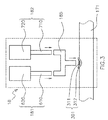
- the pressure-related operation unit 18 includes a first pressure stat 181 and a second pressure stat 182 both connected to a manifold 185, which is to be mounted on the refrigerant discharge pipe 171 at the single connection portion 301.
- connection portion 301 includes a hole 311 formed on the refrigerant discharge pipe 171 and a burr portion 312 surrounding the hole 311.
- the first pressure stat 181 and a second pressure stat 182 are mounted onto the manifold 185 by inserting the connection pipe 610 of the first pressure stat 181 and the connection pipe 710 of the second pressure stat 182 into the manifold 185.
- the manifold 185 is inserted into the hole 311. Additional brazing may be performed to secure the mounting by applying the molten metal to the joints, such as the joint between the connection pipe 610 and the manifold 185, the joint between the connection pipe 710 and the manifold 185, and the connection portion 301.
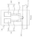
- Fig. 4 shows the state after the mounting of the first pressure stat 181, the second pressure stat 182, the manifold 185, and the refrigerant discharge pipe 171 is completed.
- the metal material used in the brazing process is omitted.
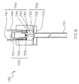
- Fig. 5 shows the structure of the first pressure stat 181.
- the first pressure stat 181 includes a connection pipe 610 and a body 620.
- the body 620 includes a pressure sensor 630 and an electrical switch 640.
- the pressure sensor 630 includes a sensing chamber 631, a membrane member 632, and a transmission rod 633.
- the electrical switch 640 includes a first terminal 641 that is connected to a movable conductor 642 with a first contact 643, and a second terminal 644 with a second contact 645.
- the connection pipe 610 serves to guide the refrigerant from the refrigerant discharge pipe 171 to the body 620 so that the pressure sensor 630 can detect the pressure of the refrigerant.
- the pressure of the refrigerant filling the sensing chamber 631 is lower than the threshold specifically designed for the first pressure stat 181, the first contact 643 and the second contact 645 keep in contact with each other, making electrical connection between the first terminal 641 and the second terminal 644, that is, the ON-state, or the close-circuit state, of the electrical switch 640.
- the threshold is 4.0 MPa with a tolerance ranging from the lower limit -0.15 MPa to the upper limit +0.0 MPa, for example.
- the actual value of the threshold of the first pressure stat 181 can be within the range from 3.85 MPa to 4.0 MPa.
- the membrane member 632 deforms and push the transmission rod 633 and hence the movable conductor 642, leading to electrical disconnection of the first terminal 641 from the second terminal 644, that is, the OFF-state, or the open-circuit state, of the electrical switch 640.
- the first pressure stat 181 is of automatically re-operative type. After the electrical switch 640 turns into the OFF-state, the electrical switch 640 can automatically return to the ON-state under a certain condition, such as the pressure of the refrigerant in the sensing chamber 631 falling below the threshold level reduced by a hysteresis, which is 3.0 MPa with a tolerance ranging from the lower limit -0.15 MPa to the upper limit +0.15 MPa, for example.
- the second pressure stat 182 includes a connection pipe 710 and a body 720.
- the body 720 includes a pressure sensor 730, an electrical switch 740, and a re-operation mechanism 750.
- the pressure sensor 730 includes a sensing chamber 731, a membrane member 732, and a transmission rod 733.
- the electrical switch 740 includes a first terminal 741 that is connected to a movable conductor 742 with a first contact 743, and a second terminal 744 with a second contact 745.
- the re-operation mechanism 750 includes a push button 751, a push bulk 752, and a spring 753.
- the connection pipe 710 serves to guide the refrigerant from the refrigerant discharge pipe 171 to the body 720 so that the pressure sensor 730 can detect the pressure of the refrigerant.
- the threshold is 4.17 MPa with a tolerance ranging from the lower limit -0.15 MPa to the upper limit +0.0 MPa, for example.
- the actual value of the threshold of the second pressure stat 182 can be within the range from 4.02 MPa to 4.17 MPa.
- the membrane member 732 deforms and push the transmission rod 733 and hence the movable conductor 742, leading to electrical disconnection of the first terminal 741 from the second terminal 744, that is, the OFF-state, or the open-circuit state, of the electrical switch 740.
- the second terminal 744 are also pressed by the transmission rod 733 and shift upward, together with the components of the re-operation mechanism 750.
- the second pressure stat 182 is of manually re-operative type. Once the electrical switch 740 turns into the OFF-state, the electrical switch 740 does not return to the ON-state unless the technician executes re-operation treatment. This is because, once an OFF-state is realized, the second terminal 744 is located upward compared to the original position, being spaced apart from the movable conductor 742 that is now restored.
- the technician uses the re-operation mechanism 750. Specifically, the technician pushes the push button 751 together with the push bulk 752, making the second terminal 744 slide back to the original position so that the first contact 743 and the second contact 745 can get in touch again.
- the first pressure stat 181 and the second pressure stat 182 are connected to the refrigerant discharge pipe 171 at the common point, i.e. the connection portion 301, via the manifold 185.
- connection pipe 610 and the connection pipe 710 have a certain length, which is desirable in particular when the first pressure stat 181 and the second pressure stat 182 are secured to the refrigerant discharge pipe 171 by brazing using hot molten metal. Due to the molten metal applied to the connection portion 301, the temperature of such connection portions becomes extremely high.
- the certain length of the connection pipe 610 and the connection pipe 710 desirably restrains the functional portions, such as the pressure sensor 630, the electrical switch 640, the pressure sensor 730, and the electrical switch 740, from being damaged due to such extreme heat.
- the pressure-related operation unit 18 is preferably mounted close to the compressor 11.
- Fig. 7 shows the structure of the refrigerant circuit 40 in the outdoor unit 10.
- the outdoor unit 10 has a casing 101 surrounding the inner space, which is divided into the heat exchanger room 102 and the actuator room 103 by means of a separation wall 104.
- the actuator room 103 is accommodated the compressor 11, the four way valve 12, the refrigerant discharge pipe 171 with the muffler 173, the accumulator 174, the pressure-related operation unit 18, and so on.
- the pressure-related operation unit 18 is arranged in the actuator room 103 so as to be located close to the discharge port 111 of the compressor 11 along the refrigerant discharge pipe 171. This close arrangement helps secure detection of abnormal rise of the refrigerant pressure. If the distance between the compressor 11 and the pressure-related operation unit 18 is designed long, such a long flow path may cause some pressure loss, which may reduce the pressure values detected by the first pressure stat 181 and the second pressure stat 182, and therefore inhibit detection of rise of the refrigerant pressure.
- Fig. 8 shows the structure of the refrigerant circuit 40 in the actuator room 103.
- the refrigerant discharge pipe 171 includes several portions, such as the outlet portion 171 a, the muffler 173 which can be omitted, the U-shaped portion 171b, the vertically extending portion 171c, the laterally extending portion 171 d, and portions that are invisible in this figure.
- the outlet portion 171 a is a pipe directly connected to the discharge port 111 of the compressor 11.
- the U-shaped portion 17b is connected the outlet of the muffler 173.
- the vertically extending portion 171 c extends right after the U-shaped portion 172.
- the laterally extending portion 171d extends generally in the horizontal direction and specifically inclines at the angle within the range from -10 degree to +10 degree with regard to the horizontal plane, for example.
- the pressure-related operation unit 18 is mounted at the laterally extending portion 171d.
- This arrangement in which the connection pipe 610 and the connection pipe 710 are oriented vertically, restrains the stress due to the gravitation from applying to the connection portion 301 on the refrigerant discharge pipe 171, thereby reducing the risk that the refrigerant discharge pipe 171 may rapture.
- the diameter of the laterally extending portion 171 d may be made larger than the diameter of the outlet portion 171 a, which can be directly/indirectly connected to the laterally extending portion 171 d. It is advantageous to arrange the connection portion 301 on the laterally extending portion 171 d having a larger diameter and therefore an enhanced strength in terms of stress endurance.
- the laterally extending portion 171d has a diameter of 3/8 inch or more.
- At least part of the actuators, such as the compressor 11, is quickly deactivated, and then the pressure of the refrigerant is restrained from increasing any longer. In this way, refrigerant leakage is restrained from occurring.
- the first pressure stat 181 Since the first pressure stat 181 has a lower threshold than that of the second pressure stat 182, the first pressure stat 181 essentially tends to detect the abnormal pressure faster than the second pressure stat 182. However, in some cases, the detection by the second pressure stat 182 may be faster depending on the shape of manifold 185, which can affect the degree of pressure loss with regard to each of first pressure stat 181 and the second pressure stat 182.
- the first pressure stat 181 and the second pressure stat 182 are connected altogether to the single connection portion 301 of the refrigerant discharge pipe 171. Accordingly, in the manufacture of the air conditioning system 100, dealing with only one connecting portion 301 suffices for install of the plurality of pressure stats to the refrigerant discharge pipe 171. Therefore, the manufacturing process of the air conditioning system 100 becomes easier.
- the first pressure stat 181 and the second pressure stat 182 s can be connected to the refrigerant discharge pipe 171 via one hole 311 or a plurality of holes closely formed at the single connection portion 301.
- the air conditioning system has an outdoor unit 10 that accommodates the outdoor heat exchanger 13, the compressor 11, the refrigerant discharge pipe 171, the first pressure stat 181, and the second pressure stat 182.
- the manifold 185 connects the single connection portion 301 with each of the first pressure stat 181 and the second pressure stat 182. Accordingly, the manufacturing processes of the air conditioning system 100 are made easier by means of the manifold 185.
- the first pressure stat 181, the second pressure stat 182, and the manifold 185 are integrally formed as one piece. This formation may be performed by integral molding, for example. Accordingly, they are firmly fixed and are easier to be mounted on the refrigerant discharge pipe 171.
- the single connection portion 301 is located at the second pipe, i.e. the laterally extending portion 171 d. Accordingly, the single connection portion 301 is arranged in a region with high stress endurance.
- at least the second pipe has a diameter of 3/8 inch or more.
- the electrical switch 640 and the electrical switch 740 is electrically connected in series. Accordingly, shutdown of the electrical circuit 50 can be achieved by operation of only either one of the electrical switch 640 and the electrical switch 740 connected in series.
- the number of the pressure stats is two. Accordingly, refrigerant leakage due to an increase of pressure is restrained at low cost and in a more secure manner.
- the refrigerant used in the refrigerant circuit 40 is flammable.
- An example of such a flammable refrigerant is R32.
- Such a flammable refrigerant is preferably used for the above-mentioned air conditioning system 100 which reduces the risk of refrigerant leakage.
- the air conditioning system 100 employs two pressure stats. However, the air conditioning system may have more than three pressure stats. With this configuration, refrigerant leakage can be restrained more securely.
- the air conditioning system 100 according to the second embodiment differs from the first embodiment only in the structure of the pressure-related operation unit 18, while being common in the other features.
- Fig. 9A shows the pressure-related operation unit 18 according to the second embodiment.
- brazing molten metal to fix the first pressure stat 181, the second pressure stat 182, the manifold 185, and the refrigerant discharge pipe 171 to each other is omitted.
- the pressure-related operation unit 18 includes a reinforcement joint 33 mounted on the refrigerant discharge pipe 171.
- the reinforcement joint 33 securely supports the manifold 185 with regard to the refrigerant discharge pipe 171.
- the reinforcement joint 33 has a branching portion 332 branching from a main portion 331.
- the branching portion 332 is positioned at the hole 311 of the refrigerant discharge pipe 171.
- the branching portion 332 is configured to receive the manifold 185.
- the single connection portion 301 is located at the reinforcement joint 33 mounted on the refrigerant discharge pipe 171.
- the reinforcement joint 33 has a branching portion 332 at the position corresponding to the single connection portion 301 so as to be connected with the plurality of pressure stats. Accordingly the single connection portion 301 shows higher stress endurance due to the reinforcement joint 33.
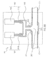
- Fig. 9B shows the pressure-related operation unit 18 according to a variation of the second embodiment. Brazing molten metal is omitted in this figure.
- the pressure-related operation unit 18 includes a reinforcement joint 33 mounted on the refrigerant discharge pipe 171.
- the reinforcement joint 33 securely supports the manifold 185 with regard to the refrigerant discharge pipe 171.
- the refrigerant discharge pipe 171 is divided into two parts.
- the gap between these two parts contributes to constitution of the connection portion 301.
- the pressure-related operation unit 18 can be assembled in advance of the first pressure stat 181, the second pressure stat 182, the manifold 185, and the reinforcement joint 33. Accordingly, it is easy for the worker to mount the pressure-related operation unit 18 on the refrigerant discharge pipe 171.
- the air conditioning system 100 according to the third embodiment differs from the first and second embodiments only in the structure of the pressure-related operation unit 18, while being common in the other features.
- Fig. 10A shows the pressure-related operation unit 18 according to the third embodiment.
- brazing molten metal to fix the first pressure stat 181, the second pressure stat 182, the manifold 185, and the refrigerant discharge pipe 171 to each other is omitted.
- the pressure-related operation unit 18 includes a first pressure stat 181 and a second pressure stat 182 arranged relatively close to each other.
- the body 620 of the first pressure stat 181 is fixed to the body 720 of the second pressure stat 182 by means of the banding band 183A, which functions as a fixing means.
- the connection pipe 610 of the first pressure stat 181 and the connection pipe 710 of the second pressure stat 182 are commonly connected to the manifold 185, which is connected to the connection portion 301 of the refrigerant discharge pipe 171.
- the first pressure stat 181 and the second pressure stat 182 move together when they receive vibration from the compressor 11. Accordingly, the first pressure stat 181 and the second pressure stat 182 are restrained from colliding with each other into breakdown.
- first pressure stat 181 and the second pressure stat 182 are fixed to each other at their bodies 620, 720. Accordingly, the bodies are stably fixed.
- Fig. 10B shows the pressure-related operation unit 18 according to a first variation of the third embodiment.
- the body 620 of the first pressure stat 181 is fixed to the body 720 of the second pressure stat 182 by means of a deformable and/or sticky material 183B.
- the first pressure stat 181 and the second pressure stat 182 move together when they receive vibration from the compressor 11. Accordingly, the first pressure stat 181 and the second pressure stat 182 are restrained from colliding with each other into breakdown.
- Fig. 10C shows the pressure-related operation unit 18 according to a second variation of the third embodiment.
- the first pressure stat 181, the second pressure stat 182, and the manifold 185 are integrally formed with a resin material 183C.
- first pressure stat 181 and the second pressure stat 182 are integrally formed as one piece having a plurality of pressure sensors, i.e. the pressure sensor 630 and the pressure sensor 730.
- This configuration may be produced by integral molding, for example.
- the first pressure stat 181 and the second pressure stat 182 in the integrated body are commonly connected to the single connection portion 301 of the refrigerant discharge pipe 171.
- first pressure stat 181 and the second pressure stat 182 are firmly fixed and are easier to be mounted on the refrigerant discharge pipe 171.
- the pressure-related operation unit 18 can employ other types of fixing means, such as a metal member, or a combination of the fixing means mentioned so far.
- fixing means enable the first pressure stat 181 and the second pressure stat 182 to be stably fixed in a more desirable manner.
Landscapes
- Engineering & Computer Science (AREA)
- Physics & Mathematics (AREA)
- Mechanical Engineering (AREA)
- Thermal Sciences (AREA)
- General Engineering & Computer Science (AREA)
- Fluid Mechanics (AREA)
- Other Air-Conditioning Systems (AREA)
Abstract
An air conditioning system (100) comprises a refrigerant circuit (40) and an electrical circuit (50). The refrigerant circuit (40) includes an indoor heat exchanger (22), an outdoor heat exchanger (13), a compressor (11), a refrigerant pipe (171), and a plurality of pressure stats (181, 182). The refrigerant pipe (171) is connected to the compressor (11) and forming at least part of the refrigerant circuit (40). The plurality of pressure stats (181, 182) is configured to detect pressure of the refrigerant in the refrigerant pipe (171). The electrical circuit (50) is configured to drive the refrigerant circuit (40). Each of the plurality of the pressure stats (181, 182) includes a pressure sensor (630, 730) and an electrical switch (640, 740). The pressure sensor (630, 730) is configured to detect pressure of the refrigerant in the refrigerant pipe (171). The electrical switch (640, 740) is configured to stop the electrical circuit (50) from driving the refrigerant circuit (40) at least partially in accordance with the pressure detected by the respective pressure sensor (630, 730). Each of the plurality of the pressure stats (181, 182) is connected to a single connection portion (301) of the refrigerant pipe (171).
Description
- This invention relates to an air conditioning system with a refrigerant circuit having an indoor heat exchanger, an outdoor heat exchanger, and a compressor.
- An air conditioner circulates refrigerant in its refrigerant circuit. Such a refrigerant circuit is required to have sufficient stress endurance so that the air conditioner can retain its performance as well as the refrigerant could be prevented from affecting the outside environment in some form due to leakage. The pressure of the refrigerant is preferably observed just after being compressed by the compressor. For this purpose, some air conditioners employ a pressure stat, which is also referred to as an HPS (high pressure switch) unit, in the outdoor unit having the compressor. The pressure stat is a combinational device of a pressure sensor and an electrical switch. When the pressure sensor detects high pressure over a predetermined threshold, the electrical switch shuts down the electrical circuit that is configured to drive the refrigerant circuit.
- Clearly it is more desirable in order to restrain leakage that an air conditioner should employ a plurality of pressure stat in case of malfunction and/or breakdown of one of the pressure stats.
- However, in the manufacture of the air conditioning system, the process of attaching pressure stats on a refrigerant pipe is generally difficult for workers because they have to connect the pressure stats with not only the refrigerant pipe but also the electrical circuit within the limited space inside the casing that accommodates a variety of mechanism. Therefore, the more pressure stats should be attached, the more difficult the attaching process becomes.
- It is therefore an object of the present invention to provide an air conditioning system with a plurality of pressure stats to prevent refrigerant from leakage, which allows easier manufacturing processes.
- According to the first aspect of the invention, there is provided an air conditioning system comprising a refrigerant circuit and an electrical circuit. The refrigerant circuit includes an indoor heat exchanger, an outdoor heat exchanger, a compressor, a refrigerant pipe, and a plurality of pressure stats. The refrigerant pipe is connected to the compressor and forming at least part of the refrigerant circuit. The plurality of pressure stats is configured to detect pressure of the refrigerant in the refrigerant pipe. The electrical circuit is configured to drive the refrigerant circuit. Each of the plurality of the pressure stats includes a pressure sensor and an electrical switch. The pressure sensor is configured to detect pressure of the refrigerant in the refrigerant pipe. The electrical switch is configured to stop the electrical circuit from driving the refrigerant circuit at least partially in accordance with the pressure detected by the respective pressure sensor. Each of the plurality of the pressure stats is connected to a single connection portion of the refrigerant pipe.
- With this configuration, a plurality of pressure stats is connected altogether to the single connection portion of the refrigerant pipe. Accordingly, in the manufacture of the air conditioning system, dealing with only one connecting portion suffices for install of the plurality of pressure stats to the refrigerant pipe. Therefore, the manufacturing process of the air conditioning system becomes easier. The plurality of pressure stats can be connected to the refrigerant pipe via one hole or a plurality of holes closely formed at the single connection portion.
- Preferably, the air conditioning system has an outdoor unit that accommodates the outdoor heat exchanger, the compressor, the refrigerant pipe, and the plurality of the pressure stats.
- According to a preferred embodiment of the air conditioning system noted above, the refrigerant circuit further includes a manifold connecting the single connection portion with each of the pressure stats.
- With this configuration, the manifold connects the single connection portion with each of the pressure stats. Accordingly, the manufacturing processes of the air conditioning system are made easier by means of the manifold.
- According to a further preferred embodiment of the air conditioning system with the refrigerant circuit including a manifold, the plurality of pressure stats and the manifold are integrally formed.
- With this configuration, the pressure stats and the manifold are integrally formed as one piece. This formation may be performed by integral molding, for example. Accordingly, they are firmly fixed and are easier to be mounted on the refrigerant pipe.
- According to another preferred embodiment of any one of the air conditioning systems mentioned above, the plurality of the pressure stats are fixed to each other at least partially.
- With this configuration, the pressure stats move together when they received vibration from the compressor. Accordingly, the pressure stats are restrained from colliding with each other into breakdown.
- According to a further preferred embodiment of the air conditioning system with the plurality of the pressure stats fixed to each other at least partially, the plurality of the pressure stats are fixed to each other by means of a fixing means. The fixing means includes at least one of a banding band, a deformable material, resin, and a metal member.
- With this configuration, the pressure stats are fixed to each other by means of the fixing means, such as a banding band, a deformable material, resin, a metal member, and some combinations of them. Accordingly, the plurality of the pressure stats is stably fixed.
- According to another preferred embodiment of any one of the air conditioning systems mentioned above, the refrigerant pipe includes a first pipe having a first diameter and a second pipe having a second diameter larger than the first diameter. The first pipe is connected to the compressor. The second pipe is connected to the first pipe. The single connection portion is located at the second pipe.
- With this configuration, the single connection portion is located at the second pipe. Accordingly, the single connection portion is arranged in a region with high stress endurance. Preferably, at least the second pipe has a diameter of 3/8 inch or more.
- According to another preferred embodiment of any one of the air conditioning systems mentioned above, the air conditioning system further comprises a reinforcement joint mounted on the refrigerant pipe, wherein the reinforcement joint is located at the single connection portion.
- With this configuration, the single connection portion is located at the reinforcement joint mounted on the refrigerant pipe. Preferably, the reinforcement joint has a branching portion at the position corresponding to the single connection portion so as to be connected with the plurality of pressure stats. Accordingly the single connection portion shows higher stress endurance due to the reinforcement joint.
- According to another preferred embodiment of any one of the air conditioning systems, at least part of the electrical switches in the plurality of the pressure stats is electrically connected in series.
- With this configuration, at least part of the plurality of electrical switches is electrically connected in series. Accordingly, shutdown of the electrical circuit can be achieved by operation of only either one of the electrical switches connected in series.
- According to another preferred embodiment of any one of the air conditioning systems mentioned above, the refrigerant circuit includes two pressure sensors.
- With this configuration, the number of the pressure stats is two. Accordingly, refrigerant leakage due to an increase of pressure is restrained at low cost and in a more secure manner.
- According to another preferred embodiment of any one of the air conditioning systems mentioned above, the refrigerant is flammable.
- With this configuration, the refrigerant used in the refrigerant circuit is flammable. An example of such a flammable refrigerant is R32. Such a flammable refrigerant is preferably used for the above-mentioned air conditioning system which reduces the risk of refrigerant leakage.
-
-
Fig. 1 is a schematic diagram of therefrigerant circuit 40 of theair conditioning system 100 according to the first embodiment of the present invention. -
Fig. 2 is a schematic diagram of theelectrical circuit 50 of theair conditioning system 100. -
Fig. 3 is a schematic diagram of the structure of the pressure-relatedoperation unit 18. -
Fig. 4 is a schematic diagram of the structure of the pressure-relatedoperation unit 18. -
Fig. 5 is a schematic diagram of the structure of thefirst pressure stat 181. -
Fig. 6 is a schematic diagram of the structure of thesecond pressure stat 182. -
Fig. 7 is a top view of therefrigerant circuit 40 in theoutdoor unit 10. -
Fig. 8 is a side view of therefrigerant circuit 40 in theoutdoor unit 10. -
Fig. 9A is a cross-sectional view of the pressure-relatedoperation unit 18 of theair conditioning system 100 according to the second embodiment of the present invention. -
Fig 9B is a cross-sectional view of the pressure-relatedoperation unit 18 of theair conditioning system 100 according to a variation of the second embodiment of the present invention. -
Figs. 10A-10C are the schematic views the pressure-relatedoperation unit 18 of theair conditioning system 100 according to the third embodiment, a first variation thereof, and a second variation thereof of the present invention, respectively. -
Fig. 1 is a schematic diagram of theair conditioning system 100 according to the first embodiment of the present invention. Theair conditioning system 100 serves to cool the room air in the cooling mode whereas heat the room air in the heating mode. Theair conditioning system 100 has arefrigerant circuit 40, which circulates refrigerant to perform refrigerant cycles. Therefrigerant circuit 40, includes anoutdoor unit 10, a firstindoor unit 20a to a fifthindoor unit 20e, and a group ofrefrigerant transportation pipes 30, each of which connects theoutdoor unit 10 and the respective one of the plurality of indoor units, i.e. the firstindoor unit 20a to the fifthindoor unit 20e. Moreover, theair conditioning system 100 has anelectrical circuit 50, which will be discussed with reference toFig. 2 later. - The refrigerant is R32 refrigerant, for example, which is flammable to some extent.
- The
outdoor unit 10 shown inFig. 1 is configured to be installed outside of the room or building and serves as a heat source, which is specifically a cold heat source in the cooling mode or a hot heat source in the heating mode. - The
outdoor unit 10 includes acompressor 11, a fourway valve 12, anoutdoor heat exchanger 13, an outdoor fan 14, and a firstoutdoor expansion valve 15a to a fifthoutdoor expansion valve 15e, as major components of therefrigerant circuit 40. Theoutdoor unit 10 further includes an outdoor heatexchanger temperature sensor 16, arefrigerant discharge pipe 171, arefrigerant suction pipe 172, a pressure-relatedoperation unit 18, and an outdoorair temperature sensor 19. - The
compressor 11 has adischarge port 111 and asuction port 112. Thecompressor 11 suctions gas-state refrigerant from thesuction port 112 through therefrigerant suction pipe 172, compresses the gas-state refrigerant, and discharges it from thedischarge port 111 through arefrigerant discharge pipe 171, along the arrow shown inFig. 1 . - The four
way valve 12 serves to change the connection of therefrigerant circuit 40 to switch theair conditioning system 100 from the cooling mode to the heating mode, or conversely. The fourway valve 12 makes the connection depicted as solid lines inFig. 1 for the cooling mode whereas it produces the connection depicted as dashed lines for the heating mode. - The
outdoor heat exchanger 13 performs heat exchange between the refrigerant and the surrounding air. Theoutdoor heat exchanger 13 functions as a condenser in the cooling mode whereas it acts as an evaporator in the heating mode. - The outdoor fan 14 facilitates the heat exchange by causing the surrounding air to contact the
outdoor heat exchanger 13. - The plurality of outdoor expansion values, i.e. the first
outdoor expansion valve 15a to the fifthoutdoor expansion valve 15e, correspond to the plurality of indoor units, i.e. the firstindoor unit 20a to the fifthindoor unit 20e, respectively. All of the firstoutdoor expansion valve 15a to the fifthoutdoor expansion valve 15e serve to decompress the refrigerant. The degree of the decompression is adjusted by controlling the actuator that is configured to change the opening degree of the outdoor expansion valve. - The
refrigerant discharge pipe 171 is connected to thedischarge port 111 of thecompressor 11 and serves to guide the compressed refrigerant that is discharged out of thecompressor 11 toward the fourway valve 12. Therefrigerant discharge pipe 171 may include amuffler 173 to reduce the noise caused by the fluctuation of the refrigerant flow although themuffler 173 is not essential. - The
refrigerant suction pipe 172 is connected to thesuction port 112 of thecompressor 11 and serves to guide the refrigerant from the fourway valve 12 to enter thecompressor 11. Therefrigerant suction pipe 172 may include anaccumulator 174, which can abstract and store some liquid-state refrigerant contained in the flowing gas-state refrigerant in order to restrain thecompressor 11 from being damaged. - The pressure-related
operation unit 18 serves to restrain the refrigerant from leaking out of therefrigerant circuit 40. As shown inFig. 1 , the pressure-relatedoperation unit 18 is mounted on therefrigerant discharge pipe 171. The detailed configuration of the pressure-relatedoperation unit 18 will be discussed later. - The outdoor heat
exchanger temperature sensor 16 serves to monitor the temperature of the refrigerant flowing through theoutdoor heat exchanger 13. The outdoorair temperature sensor 19 serves to detect the temperature of the atmosphere outside the room or building. -
Fig. 1 shows five indoor units, i.e. the firstindoor unit 20a to the fifthindoor unit 20e. The firstindoor unit 20a to the fifthindoor unit 20e serve to provide temperature-adjusted air for users in corporation with theoutdoor unit 10. The five indoor units are typically installed inside of different rooms. Alternatively, at least part of the five indoor units may be installed inside of the same room. It is clear that the number of the indoor units may be other than five, meaning one or two, for example. - Hereinafter, only the first
indoor unit 20a will be discussed, and the explanation will be omitted with regard to the remainingindoor units 20b to 20e, each of which has a substantially similar structure to that of the firstindoor unit 20a. - The first
indoor unit 20a includes anindoor heat exchanger 22, anindoor fan 23, an indoor heatexchanger temperature sensor 26, and an indoorair temperature sensor 29. - The
indoor heat exchanger 22 performs heat exchange between the refrigerant and the room air. Theindoor heat exchanger 22 functions as an evaporator in the cooling mode whereas it acts as a condenser in the heating mode. - The
indoor fan 23 facilitates the heat exchange by making the room air contact theindoor heat exchanger 22. - The indoor heat
exchanger temperature sensor 26 serves to monitor the temperature of the refrigerant flowing through theindoor heat exchanger 22. The indoorair temperature sensor 29 serves to detect the temperature of the air inside the room. - The group of
refrigerant transportation pipes 30 has a plurality of liquid-staterefrigerant transportation pipes 31 a to 31e and a plurality of gas-staterefrigerant transportation pipes 32a to 32e. Each of the liquid-staterefrigerant transportation pipes 31 a to 31e connects theoutdoor unit 10 with the respective one of the plurality of indoor units, i.e. the firstindoor unit 20a to the fifthindoor unit 20e, to allow passage of the refrigerant in a liquid-state or a gas-liquid two-phase state. Each of the gas-staterefrigerant transportation pipes 32a to 32e connects theoutdoor unit 10 with the respective one of the indoor units to allow passage of the refrigerant in a gas-state. - The
electrical circuit 50 shown inFig. 2 drives and controls a variety of actuators that are employed in therefrigerant circuit 40. Specifically, theelectrical circuit 50 controls the rotational speed of the motor of thecompressor 11, the connection of the fourway valve 12, the rotational speed of the motor of the outdoor fan 14, the opening degrees of the firstoutdoor expansion valve 15a to the fifthoutdoor expansion valve 15e, as well as the rotational speed of the motor of theindoor fan 23 for each of the firstindoor unit 20a to the fifthindoor unit 20e. - The
electrical circuit 50 also detects the state of theelectrical switches operation unit 18, which are connected in series. If the open-circuit state occurs between the terminal SW+ and the terminal SW-, which means both ends of the serially connected electrical switches, at least part of theelectrical circuit 50 shuts down, stopping supply of the power to the actuators. - In addition, the
electrical circuit 50 monitors the outdoor heatexchanger temperature sensor 16 and the outdoorair temperature sensor 19 of theoutdoor unit 10, as well as the indoor heatexchanger temperature sensor 26 and the indoorair temperature sensor 29 for each of the firstindoor unit 20a to the fifthindoor unit 20e, to properly control the air temperature in each of the rooms. - The
electrical circuit 50 may be located entirely in any one of theoutdoor unit 10 and the firstindoor unit 20a to the fifthindoor unit 20e. Alternatively, theelectrical circuit 50 may be divided into at least part of theoutdoor unit 10 and the firstindoor unit 20a to the fifthindoor unit 20e. - As shown in
Fig. 3 , the pressure-relatedoperation unit 18 includes afirst pressure stat 181 and asecond pressure stat 182 both connected to a manifold 185, which is to be mounted on therefrigerant discharge pipe 171 at thesingle connection portion 301. - The
connection portion 301 includes ahole 311 formed on therefrigerant discharge pipe 171 and aburr portion 312 surrounding thehole 311. - The
first pressure stat 181 and asecond pressure stat 182 are mounted onto the manifold 185 by inserting theconnection pipe 610 of thefirst pressure stat 181 and theconnection pipe 710 of thesecond pressure stat 182 into themanifold 185. The manifold 185 is inserted into thehole 311. Additional brazing may be performed to secure the mounting by applying the molten metal to the joints, such as the joint between theconnection pipe 610 and the manifold 185, the joint between theconnection pipe 710 and the manifold 185, and theconnection portion 301. -
Fig. 4 shows the state after the mounting of thefirst pressure stat 181, thesecond pressure stat 182, the manifold 185, and therefrigerant discharge pipe 171 is completed. In this figure, the metal material used in the brazing process is omitted. -
Fig. 5 shows the structure of thefirst pressure stat 181. Thefirst pressure stat 181 includes aconnection pipe 610 and abody 620. Thebody 620 includes apressure sensor 630 and anelectrical switch 640. Thepressure sensor 630 includes asensing chamber 631, amembrane member 632, and atransmission rod 633. Theelectrical switch 640 includes afirst terminal 641 that is connected to amovable conductor 642 with afirst contact 643, and asecond terminal 644 with asecond contact 645. - The
connection pipe 610 serves to guide the refrigerant from therefrigerant discharge pipe 171 to thebody 620 so that thepressure sensor 630 can detect the pressure of the refrigerant. While the pressure of the refrigerant filling thesensing chamber 631 is lower than the threshold specifically designed for thefirst pressure stat 181, thefirst contact 643 and thesecond contact 645 keep in contact with each other, making electrical connection between thefirst terminal 641 and thesecond terminal 644, that is, the ON-state, or the close-circuit state, of theelectrical switch 640. Here, the threshold is 4.0 MPa with a tolerance ranging from the lower limit -0.15 MPa to the upper limit +0.0 MPa, for example. In other words, the actual value of the threshold of thefirst pressure stat 181 can be within the range from 3.85 MPa to 4.0 MPa. - When the pressure of the refrigerant filling the
sensing chamber 631 exceeds the threshold, themembrane member 632 deforms and push thetransmission rod 633 and hence themovable conductor 642, leading to electrical disconnection of the first terminal 641 from thesecond terminal 644, that is, the OFF-state, or the open-circuit state, of theelectrical switch 640. - The
first pressure stat 181 is of automatically re-operative type. After theelectrical switch 640 turns into the OFF-state, theelectrical switch 640 can automatically return to the ON-state under a certain condition, such as the pressure of the refrigerant in thesensing chamber 631 falling below the threshold level reduced by a hysteresis, which is 3.0 MPa with a tolerance ranging from the lower limit -0.15 MPa to the upper limit +0.15 MPa, for example. -
Fig. 6 shows the structure of thesecond pressure stat 182. Thesecond pressure stat 182 includes aconnection pipe 710 and abody 720. Thebody 720 includes apressure sensor 730, anelectrical switch 740, and are-operation mechanism 750. Thepressure sensor 730 includes asensing chamber 731, amembrane member 732, and atransmission rod 733. Theelectrical switch 740 includes afirst terminal 741 that is connected to amovable conductor 742 with afirst contact 743, and a second terminal 744 with asecond contact 745. There-operation mechanism 750 includes apush button 751, apush bulk 752, and aspring 753. - The
connection pipe 710 serves to guide the refrigerant from therefrigerant discharge pipe 171 to thebody 720 so that thepressure sensor 730 can detect the pressure of the refrigerant. When the pressure of the refrigerant filling thesensing chamber 731 is lower than the threshold specifically designed for thesecond pressure stat 182, thefirst contact 743 and thesecond contact 745 are in contact with each other, making electrical connection between thefirst terminal 741 and the second terminal 744, that is, the ON-state, or the close-circuit state, of theelectrical switch 740. Here, the threshold is 4.17 MPa with a tolerance ranging from the lower limit -0.15 MPa to the upper limit +0.0 MPa, for example. In other words, the actual value of the threshold of thesecond pressure stat 182 can be within the range from 4.02 MPa to 4.17 MPa. - In this way, because the tolerance ranges do not overlap with regard to the
first pressure stat 181 and thesecond pressure stat 182, the relationship of the threshold levels is prevented from reversing with regard to thefirst pressure stat 181 and thesecond pressure stat 182. - When the pressure of the refrigerant filling the
sensing chamber 731 exceeds the threshold, themembrane member 732 deforms and push thetransmission rod 733 and hence themovable conductor 742, leading to electrical disconnection of the first terminal 741 from the second terminal 744, that is, the OFF-state, or the open-circuit state, of theelectrical switch 740. At this time, the second terminal 744 are also pressed by thetransmission rod 733 and shift upward, together with the components of there-operation mechanism 750. - The
second pressure stat 182 is of manually re-operative type. Once theelectrical switch 740 turns into the OFF-state, theelectrical switch 740 does not return to the ON-state unless the technician executes re-operation treatment. This is because, once an OFF-state is realized, the second terminal 744 is located upward compared to the original position, being spaced apart from themovable conductor 742 that is now restored. - For re-operation treatment, the technician uses the
re-operation mechanism 750. Specifically, the technician pushes thepush button 751 together with thepush bulk 752, making the second terminal 744 slide back to the original position so that thefirst contact 743 and thesecond contact 745 can get in touch again. - As will be understood from
Fig. 4 , thefirst pressure stat 181 and thesecond pressure stat 182 are connected to therefrigerant discharge pipe 171 at the common point, i.e. theconnection portion 301, via themanifold 185. - As shown in
Fig. 5 andFig. 6 , theconnection pipe 610 and theconnection pipe 710 have a certain length, which is desirable in particular when thefirst pressure stat 181 and thesecond pressure stat 182 are secured to therefrigerant discharge pipe 171 by brazing using hot molten metal. Due to the molten metal applied to theconnection portion 301, the temperature of such connection portions becomes extremely high. The certain length of theconnection pipe 610 and theconnection pipe 710 desirably restrains the functional portions, such as thepressure sensor 630, theelectrical switch 640, thepressure sensor 730, and theelectrical switch 740, from being damaged due to such extreme heat. - The pressure-related
operation unit 18 is preferably mounted close to thecompressor 11. -
Fig. 7 shows the structure of therefrigerant circuit 40 in theoutdoor unit 10. Theoutdoor unit 10 has acasing 101 surrounding the inner space, which is divided into theheat exchanger room 102 and theactuator room 103 by means of aseparation wall 104. In theactuator room 103 is accommodated thecompressor 11, the fourway valve 12, therefrigerant discharge pipe 171 with themuffler 173, theaccumulator 174, the pressure-relatedoperation unit 18, and so on. - It should be noted that the pressure-related
operation unit 18 is arranged in theactuator room 103 so as to be located close to thedischarge port 111 of thecompressor 11 along therefrigerant discharge pipe 171. This close arrangement helps secure detection of abnormal rise of the refrigerant pressure. If the distance between thecompressor 11 and the pressure-relatedoperation unit 18 is designed long, such a long flow path may cause some pressure loss, which may reduce the pressure values detected by thefirst pressure stat 181 and thesecond pressure stat 182, and therefore inhibit detection of rise of the refrigerant pressure. -
Fig. 8 shows the structure of therefrigerant circuit 40 in theactuator room 103. Therefrigerant discharge pipe 171 includes several portions, such as theoutlet portion 171 a, themuffler 173 which can be omitted, theU-shaped portion 171b, the vertically extendingportion 171c, the laterally extendingportion 171 d, and portions that are invisible in this figure. Theoutlet portion 171 a is a pipe directly connected to thedischarge port 111 of thecompressor 11. The U-shaped portion 17b is connected the outlet of themuffler 173. The vertically extendingportion 171 c extends right after theU-shaped portion 172. The laterally extendingportion 171d extends generally in the horizontal direction and specifically inclines at the angle within the range from -10 degree to +10 degree with regard to the horizontal plane, for example. - It should be noted that the pressure-related
operation unit 18 is mounted at the laterally extendingportion 171d. This arrangement, in which theconnection pipe 610 and theconnection pipe 710 are oriented vertically, restrains the stress due to the gravitation from applying to theconnection portion 301 on therefrigerant discharge pipe 171, thereby reducing the risk that therefrigerant discharge pipe 171 may rapture. - In addition, the diameter of the laterally extending
portion 171 d may be made larger than the diameter of theoutlet portion 171 a, which can be directly/indirectly connected to the laterally extendingportion 171 d. It is advantageous to arrange theconnection portion 301 on the laterally extendingportion 171 d having a larger diameter and therefore an enhanced strength in terms of stress endurance. Preferably, the laterally extendingportion 171d has a diameter of 3/8 inch or more. - If the pressure of the refrigerant rises to an abnormal level in the
refrigerant discharge pipe 171, such abnormal state can be detected by any one of thefirst pressure stat 181 and thesecond pressure stat 182, which can shut down at least part of theelectrical circuit 50. - Accordingly, at least part of the actuators, such as the
compressor 11, is quickly deactivated, and then the pressure of the refrigerant is restrained from increasing any longer. In this way, refrigerant leakage is restrained from occurring. - Since the
first pressure stat 181 has a lower threshold than that of thesecond pressure stat 182, thefirst pressure stat 181 essentially tends to detect the abnormal pressure faster than thesecond pressure stat 182. However, in some cases, the detection by thesecond pressure stat 182 may be faster depending on the shape ofmanifold 185, which can affect the degree of pressure loss with regard to each offirst pressure stat 181 and thesecond pressure stat 182. - The
first pressure stat 181 and thesecond pressure stat 182 are connected altogether to thesingle connection portion 301 of therefrigerant discharge pipe 171. Accordingly, in the manufacture of theair conditioning system 100, dealing with only one connectingportion 301 suffices for install of the plurality of pressure stats to therefrigerant discharge pipe 171. Therefore, the manufacturing process of theair conditioning system 100 becomes easier. Thefirst pressure stat 181 and the second pressure stat 182 s can be connected to therefrigerant discharge pipe 171 via onehole 311 or a plurality of holes closely formed at thesingle connection portion 301. - Preferably, the air conditioning system has an
outdoor unit 10 that accommodates theoutdoor heat exchanger 13, thecompressor 11, therefrigerant discharge pipe 171, thefirst pressure stat 181, and thesecond pressure stat 182. - The manifold 185 connects the
single connection portion 301 with each of thefirst pressure stat 181 and thesecond pressure stat 182. Accordingly, the manufacturing processes of theair conditioning system 100 are made easier by means of themanifold 185. - The
first pressure stat 181, thesecond pressure stat 182, and the manifold 185 are integrally formed as one piece. This formation may be performed by integral molding, for example. Accordingly, they are firmly fixed and are easier to be mounted on therefrigerant discharge pipe 171. - The
single connection portion 301 is located at the second pipe, i.e. the laterally extendingportion 171 d. Accordingly, thesingle connection portion 301 is arranged in a region with high stress endurance. Preferably, at least the second pipe has a diameter of 3/8 inch or more. - The
electrical switch 640 and theelectrical switch 740 is electrically connected in series. Accordingly, shutdown of theelectrical circuit 50 can be achieved by operation of only either one of theelectrical switch 640 and theelectrical switch 740 connected in series. - The number of the pressure stats is two. Accordingly, refrigerant leakage due to an increase of pressure is restrained at low cost and in a more secure manner.
- The refrigerant used in the
refrigerant circuit 40 is flammable. An example of such a flammable refrigerant is R32. Such a flammable refrigerant is preferably used for the above-mentionedair conditioning system 100 which reduces the risk of refrigerant leakage. - The
air conditioning system 100 according to the above-mentioned embodiment employs two pressure stats. However, the air conditioning system may have more than three pressure stats. With this configuration, refrigerant leakage can be restrained more securely. - The
air conditioning system 100 according to the second embodiment differs from the first embodiment only in the structure of the pressure-relatedoperation unit 18, while being common in the other features. -
Fig. 9A shows the pressure-relatedoperation unit 18 according to the second embodiment. In this figure, brazing molten metal to fix thefirst pressure stat 181, thesecond pressure stat 182, the manifold 185, and therefrigerant discharge pipe 171 to each other is omitted. - The pressure-related
operation unit 18 includes a reinforcement joint 33 mounted on therefrigerant discharge pipe 171. The reinforcement joint 33 securely supports the manifold 185 with regard to therefrigerant discharge pipe 171. The reinforcement joint 33 has a branchingportion 332 branching from amain portion 331. The branchingportion 332 is positioned at thehole 311 of therefrigerant discharge pipe 171. The branchingportion 332 is configured to receive themanifold 185. - With this configuration, the
single connection portion 301 is located at the reinforcement joint 33 mounted on therefrigerant discharge pipe 171. The reinforcement joint 33 has a branchingportion 332 at the position corresponding to thesingle connection portion 301 so as to be connected with the plurality of pressure stats. Accordingly thesingle connection portion 301 shows higher stress endurance due to the reinforcement joint 33. -
Fig. 9B shows the pressure-relatedoperation unit 18 according to a variation of the second embodiment. Brazing molten metal is omitted in this figure. - Similarly to the original configuration of the second embodiment, the pressure-related
operation unit 18 includes a reinforcement joint 33 mounted on therefrigerant discharge pipe 171. The reinforcement joint 33 securely supports the manifold 185 with regard to therefrigerant discharge pipe 171. - In this variation, the
refrigerant discharge pipe 171 is divided into two parts. The gap between these two parts contributes to constitution of theconnection portion 301. - With this configuration, the pressure-related
operation unit 18 can be assembled in advance of thefirst pressure stat 181, thesecond pressure stat 182, the manifold 185, and the reinforcement joint 33. Accordingly, it is easy for the worker to mount the pressure-relatedoperation unit 18 on therefrigerant discharge pipe 171. - The
air conditioning system 100 according to the third embodiment differs from the first and second embodiments only in the structure of the pressure-relatedoperation unit 18, while being common in the other features. -
Fig. 10A shows the pressure-relatedoperation unit 18 according to the third embodiment. In this figure, brazing molten metal to fix thefirst pressure stat 181, thesecond pressure stat 182, the manifold 185, and therefrigerant discharge pipe 171 to each other is omitted. - The pressure-related
operation unit 18 includes afirst pressure stat 181 and asecond pressure stat 182 arranged relatively close to each other. Thebody 620 of thefirst pressure stat 181 is fixed to thebody 720 of thesecond pressure stat 182 by means of thebanding band 183A, which functions as a fixing means. Theconnection pipe 610 of thefirst pressure stat 181 and theconnection pipe 710 of thesecond pressure stat 182 are commonly connected to the manifold 185, which is connected to theconnection portion 301 of therefrigerant discharge pipe 171. - With this configuration, the
first pressure stat 181 and thesecond pressure stat 182 move together when they receive vibration from thecompressor 11. Accordingly, thefirst pressure stat 181 and thesecond pressure stat 182 are restrained from colliding with each other into breakdown. - Further, the
first pressure stat 181 and thesecond pressure stat 182 are fixed to each other at theirbodies -
Fig. 10B shows the pressure-relatedoperation unit 18 according to a first variation of the third embodiment. Thebody 620 of thefirst pressure stat 181 is fixed to thebody 720 of thesecond pressure stat 182 by means of a deformable and/orsticky material 183B. - With this configuration, the
first pressure stat 181 and thesecond pressure stat 182 move together when they receive vibration from thecompressor 11. Accordingly, thefirst pressure stat 181 and thesecond pressure stat 182 are restrained from colliding with each other into breakdown. -
Fig. 10C shows the pressure-relatedoperation unit 18 according to a second variation of the third embodiment. Thefirst pressure stat 181, thesecond pressure stat 182, and the manifold 185 are integrally formed with aresin material 183C. - With this configuration, the
first pressure stat 181 and thesecond pressure stat 182 are integrally formed as one piece having a plurality of pressure sensors, i.e. thepressure sensor 630 and thepressure sensor 730. This configuration may be produced by integral molding, for example. Thefirst pressure stat 181 and thesecond pressure stat 182 in the integrated body are commonly connected to thesingle connection portion 301 of therefrigerant discharge pipe 171. - Accordingly, the
first pressure stat 181 and thesecond pressure stat 182 are firmly fixed and are easier to be mounted on therefrigerant discharge pipe 171. - Instead of the
banding band 183A, the deformable and/orsticky material 183B, or theresin material 183C, the pressure-relatedoperation unit 18 can employ other types of fixing means, such as a metal member, or a combination of the fixing means mentioned so far. - Accordingly, such a variety of fixing means enable the
first pressure stat 181 and thesecond pressure stat 182 to be stably fixed in a more desirable manner. - 11
- compressor
- 13
- outdoor heat exchanger
- 23
- indoor heat exchanger
- 33
- reinforcement joint
- 40
- refrigerant circuit
- 50
- electrical circuit
- 100
- air conditioning system
- 171
- refrigerant discharge pipe
- 171a
- outlet portion
- 171d
- laterally extending portion
- 181
- first pressure stat
- 182
- second pressure stat
- 185
- manifold
- 301
- connection portion
- 610, 710
- connection pipe
- 620, 720
- body
- 630, 730
- pressure sensor
- 640, 740
- electrical switch
Claims (10)
- An air conditioning system (100) comprising:a refrigerant circuit (40) including:an indoor heat exchanger (22),an outdoor heat exchanger (13),a compressor (11),a refrigerant pipe (171) connected to the compressor and forming at least part of the refrigerant circuit, anda plurality of pressure stats (181, 182) configured to detect pressure of the refrigerant in the refrigerant pipe; andan electrical circuit (50) configured to drive the refrigerant circuit;whereineach of the plurality of the pressure stats includes:a pressure sensor (630, 730) configured to detect pressure of the refrigerant in the refrigerant pipe; andan electrical switch (640, 740) configured to stop the electrical circuit from driving the refrigerant circuit at least partially in accordance with the pressure detected by the respective pressure sensor, andeach of the plurality of the pressure stats is connected to a single connection portion (301) of the refrigerant pipe.
- The air conditioning system according to Claim 1, wherein the refrigerant circuit further includes a manifold (185) connecting the single connection portion with each of the pressure stats.
- The air conditioning system according to Claims 2, wherein the plurality of pressure stats and the manifold are integrally formed.
- The air conditioning system according to any one of Claims 1 to 3, wherein the plurality of the pressure stats are fixed to each other at least partially.
- The air conditioning system according to Claim 4, wherein
the plurality of the pressure stats are fixed to each other by means of a fixing means, and
the fixing means includes at least one of a banding band (183A), a deformable material (183B), resin (183C), and a metal member. - The air conditioning system according to any one of Claims 1 to 5, wherein
the refrigerant pipe includes a first pipe (171 a) having a first diameter and a second pipe (171 d) having a second diameter larger than the first diameter,
the first pipe is connected to the compressor,
the second pipe is connected to the first pipe, and
the single connection portion is located at the second pipe. - The air conditioning system according to any one of Claims 1 to 6, further comprising a reinforcement joint (33) mounted on the refrigerant pipe, wherein the reinforcement joint is located at the single connection portion.
- The air conditioning system according to any one of Claims 1 to 7, wherein at least part of the electrical switches in the plurality of the pressure stats are electrically connected in series.
- The air conditioning system according to any one of Claims 1 to 8, wherein the refrigerant circuit includes two pressure sensors.
- The air conditioning system according to any one of Claims 1 to 9, wherein the refrigerant is flammable.
Priority Applications (1)
| Application Number | Priority Date | Filing Date | Title |
|---|---|---|---|
| EP16153426.8A EP3199892A1 (en) | 2016-01-29 | 2016-01-29 | Air conditioning system |
Applications Claiming Priority (1)
| Application Number | Priority Date | Filing Date | Title |
|---|---|---|---|
| EP16153426.8A EP3199892A1 (en) | 2016-01-29 | 2016-01-29 | Air conditioning system |
Publications (1)
| Publication Number | Publication Date |
|---|---|
| EP3199892A1 true EP3199892A1 (en) | 2017-08-02 |
Family
ID=55273155
Family Applications (1)
| Application Number | Title | Priority Date | Filing Date |
|---|---|---|---|
| EP16153426.8A Withdrawn EP3199892A1 (en) | 2016-01-29 | 2016-01-29 | Air conditioning system |
Country Status (1)
| Country | Link |
|---|---|
| EP (1) | EP3199892A1 (en) |
Cited By (1)
| Publication number | Priority date | Publication date | Assignee | Title |
|---|---|---|---|---|
| US11852131B2 (en) | 2017-09-25 | 2023-12-26 | Carrier Corporation | Pressure safety shutoff |
Citations (4)
| Publication number | Priority date | Publication date | Assignee | Title |
|---|---|---|---|---|
| US4614087A (en) * | 1983-08-09 | 1986-09-30 | Nihon Radiator Co., Ltd. | Apparatus for alarming abnormal coolant in space cooling cycle |
| EP0488775A2 (en) * | 1990-11-30 | 1992-06-03 | Sanden Corporation | Detecting system for detecting an insufficient amount of refrigerant in a cooling apparatus and compressor control system incorporating same |
| US20080264080A1 (en) * | 2007-04-24 | 2008-10-30 | Hunter Manufacturing Co. | Environmental control unit for harsh conditions |
| US20110048041A1 (en) * | 2008-01-17 | 2011-03-03 | Carrier Corporation | Pressure relief in high pressure refrigeration system |
-
2016
- 2016-01-29 EP EP16153426.8A patent/EP3199892A1/en not_active Withdrawn
Patent Citations (4)
| Publication number | Priority date | Publication date | Assignee | Title |
|---|---|---|---|---|
| US4614087A (en) * | 1983-08-09 | 1986-09-30 | Nihon Radiator Co., Ltd. | Apparatus for alarming abnormal coolant in space cooling cycle |
| EP0488775A2 (en) * | 1990-11-30 | 1992-06-03 | Sanden Corporation | Detecting system for detecting an insufficient amount of refrigerant in a cooling apparatus and compressor control system incorporating same |
| US20080264080A1 (en) * | 2007-04-24 | 2008-10-30 | Hunter Manufacturing Co. | Environmental control unit for harsh conditions |
| US20110048041A1 (en) * | 2008-01-17 | 2011-03-03 | Carrier Corporation | Pressure relief in high pressure refrigeration system |
Cited By (1)
| Publication number | Priority date | Publication date | Assignee | Title |
|---|---|---|---|---|
| US11852131B2 (en) | 2017-09-25 | 2023-12-26 | Carrier Corporation | Pressure safety shutoff |
Similar Documents
| Publication | Publication Date | Title |
|---|---|---|
| JP5446064B2 (en) | Heat exchange system | |
| US7010927B2 (en) | Refrigerant system with controlled refrigerant charge amount | |
| US10101041B2 (en) | HVAC unit with hot gas reheat | |
| EP2992275B1 (en) | System comprising first and second compressors | |
| EP1443287B1 (en) | Multi-type air conditioner with plurality of distributor able to be shut off | |
| US6925823B2 (en) | Refrigerant cycle with operating range extension | |
| CN104937350B (en) | Air-conditioning device | |
| US20130255932A1 (en) | Heat sink for a condensing unit and method of using same | |
| US7797956B2 (en) | Air conditioning apparatus | |
| US10976090B2 (en) | Air conditioner | |
| US10712033B2 (en) | Control of HVAC unit based on sensor status | |
| EP3279580A1 (en) | Air-conditioning device | |
| EP3312528B1 (en) | Air conditioner | |
| EP3722687B1 (en) | Air conditioning apparatus | |
| EP3159630B1 (en) | Air conditioner | |
| EP3130868A1 (en) | Heat pump system | |
| WO2008069265A1 (en) | Air-conditioner | |
| EP3200215B1 (en) | Air conditioning system | |
| EP2019273A1 (en) | Refrigeration device | |
| EP3199888A1 (en) | Air conditioning system | |
| US6640567B2 (en) | Air conditioning system with low compression load | |
| EP1655556A1 (en) | Air-conditioning system and apparatus for protecting the same | |
| JP4176677B2 (en) | Air conditioner | |
| EP4682444A1 (en) | Outdoor unit comprising a release device | |
| KR100829187B1 (en) | Electronic expansion valve and multi-type air conditioning system with no power supply valve |
Legal Events
| Date | Code | Title | Description |
|---|---|---|---|
| PUAI | Public reference made under article 153(3) epc to a published international application that has entered the european phase |
Free format text: ORIGINAL CODE: 0009012 |
|
| STAA | Information on the status of an ep patent application or granted ep patent |
Free format text: STATUS: THE APPLICATION HAS BEEN PUBLISHED |
|
| AK | Designated contracting states |
Kind code of ref document: A1 Designated state(s): AL AT BE BG CH CY CZ DE DK EE ES FI FR GB GR HR HU IE IS IT LI LT LU LV MC MK MT NL NO PL PT RO RS SE SI SK SM TR |
|
| AX | Request for extension of the european patent |
Extension state: BA ME |
|
| STAA | Information on the status of an ep patent application or granted ep patent |
Free format text: STATUS: THE APPLICATION IS DEEMED TO BE WITHDRAWN |
|
| 18D | Application deemed to be withdrawn |
Effective date: 20180203 |