EP3199850A1 - Bleed valve position sensor - Google Patents
Bleed valve position sensor Download PDFInfo
- Publication number
- EP3199850A1 EP3199850A1 EP17153803.6A EP17153803A EP3199850A1 EP 3199850 A1 EP3199850 A1 EP 3199850A1 EP 17153803 A EP17153803 A EP 17153803A EP 3199850 A1 EP3199850 A1 EP 3199850A1
- Authority
- EP
- European Patent Office
- Prior art keywords
- piston
- position sensor
- valve
- core
- coil
- Prior art date
- Legal status (The legal status is an assumption and is not a legal conclusion. Google has not performed a legal analysis and makes no representation as to the accuracy of the status listed.)
- Withdrawn
Links
- 239000000919 ceramic Substances 0.000 claims description 2
- 239000000843 powder Substances 0.000 claims description 2
- 238000005538 encapsulation Methods 0.000 claims 1
- 230000004075 alteration Effects 0.000 description 1
- 230000008859 change Effects 0.000 description 1
- 230000008878 coupling Effects 0.000 description 1
- 238000010168 coupling process Methods 0.000 description 1
- 238000005859 coupling reaction Methods 0.000 description 1
- 230000005294 ferromagnetic effect Effects 0.000 description 1
- 238000000034 method Methods 0.000 description 1
- 238000012986 modification Methods 0.000 description 1
- 230000004048 modification Effects 0.000 description 1
- 238000007789 sealing Methods 0.000 description 1
- 238000006467 substitution reaction Methods 0.000 description 1
Images


Classifications
-
- F—MECHANICAL ENGINEERING; LIGHTING; HEATING; WEAPONS; BLASTING
- F16—ENGINEERING ELEMENTS AND UNITS; GENERAL MEASURES FOR PRODUCING AND MAINTAINING EFFECTIVE FUNCTIONING OF MACHINES OR INSTALLATIONS; THERMAL INSULATION IN GENERAL
- F16K—VALVES; TAPS; COCKS; ACTUATING-FLOATS; DEVICES FOR VENTING OR AERATING
- F16K37/00—Special means in or on valves or other cut-off apparatus for indicating or recording operation thereof, or for enabling an alarm to be given
- F16K37/0025—Electrical or magnetic means
- F16K37/0041—Electrical or magnetic means for measuring valve parameters
-
- B—PERFORMING OPERATIONS; TRANSPORTING
- B64—AIRCRAFT; AVIATION; COSMONAUTICS
- B64D—EQUIPMENT FOR FITTING IN OR TO AIRCRAFT; FLIGHT SUITS; PARACHUTES; ARRANGEMENT OR MOUNTING OF POWER PLANTS OR PROPULSION TRANSMISSIONS IN AIRCRAFT
- B64D13/00—Arrangements or adaptations of air-treatment apparatus for aircraft crew or passengers, or freight space
-
- B—PERFORMING OPERATIONS; TRANSPORTING
- B64—AIRCRAFT; AVIATION; COSMONAUTICS
- B64D—EQUIPMENT FOR FITTING IN OR TO AIRCRAFT; FLIGHT SUITS; PARACHUTES; ARRANGEMENT OR MOUNTING OF POWER PLANTS OR PROPULSION TRANSMISSIONS IN AIRCRAFT
- B64D13/00—Arrangements or adaptations of air-treatment apparatus for aircraft crew or passengers, or freight space
- B64D13/02—Arrangements or adaptations of air-treatment apparatus for aircraft crew or passengers, or freight space the air being pressurised
- B64D13/04—Automatic control of pressure
-
- F—MECHANICAL ENGINEERING; LIGHTING; HEATING; WEAPONS; BLASTING
- F02—COMBUSTION ENGINES; HOT-GAS OR COMBUSTION-PRODUCT ENGINE PLANTS
- F02C—GAS-TURBINE PLANTS; AIR INTAKES FOR JET-PROPULSION PLANTS; CONTROLLING FUEL SUPPLY IN AIR-BREATHING JET-PROPULSION PLANTS
- F02C6/00—Plural gas-turbine plants; Combinations of gas-turbine plants with other apparatus; Adaptations of gas-turbine plants for special use
- F02C6/04—Gas-turbine plants providing heated or pressurised working fluid for other apparatus, e.g. without mechanical power output
- F02C6/06—Gas-turbine plants providing heated or pressurised working fluid for other apparatus, e.g. without mechanical power output providing compressed gas
- F02C6/08—Gas-turbine plants providing heated or pressurised working fluid for other apparatus, e.g. without mechanical power output providing compressed gas the gas being bled from the gas-turbine compressor
-
- F—MECHANICAL ENGINEERING; LIGHTING; HEATING; WEAPONS; BLASTING
- F02—COMBUSTION ENGINES; HOT-GAS OR COMBUSTION-PRODUCT ENGINE PLANTS
- F02C—GAS-TURBINE PLANTS; AIR INTAKES FOR JET-PROPULSION PLANTS; CONTROLLING FUEL SUPPLY IN AIR-BREATHING JET-PROPULSION PLANTS
- F02C7/00—Features, components parts, details or accessories, not provided for in, or of interest apart form groups F02C1/00 - F02C6/00; Air intakes for jet-propulsion plants
- F02C7/12—Cooling of plants
- F02C7/16—Cooling of plants characterised by cooling medium
- F02C7/18—Cooling of plants characterised by cooling medium the medium being gaseous, e.g. air
-
- F—MECHANICAL ENGINEERING; LIGHTING; HEATING; WEAPONS; BLASTING
- F16—ENGINEERING ELEMENTS AND UNITS; GENERAL MEASURES FOR PRODUCING AND MAINTAINING EFFECTIVE FUNCTIONING OF MACHINES OR INSTALLATIONS; THERMAL INSULATION IN GENERAL
- F16K—VALVES; TAPS; COCKS; ACTUATING-FLOATS; DEVICES FOR VENTING OR AERATING
- F16K1/00—Lift valves or globe valves, i.e. cut-off apparatus with closure members having at least a component of their opening and closing motion perpendicular to the closing faces
- F16K1/16—Lift valves or globe valves, i.e. cut-off apparatus with closure members having at least a component of their opening and closing motion perpendicular to the closing faces with pivoted closure-members
- F16K1/18—Lift valves or globe valves, i.e. cut-off apparatus with closure members having at least a component of their opening and closing motion perpendicular to the closing faces with pivoted closure-members with pivoted discs or flaps
- F16K1/22—Lift valves or globe valves, i.e. cut-off apparatus with closure members having at least a component of their opening and closing motion perpendicular to the closing faces with pivoted closure-members with pivoted discs or flaps with axis of rotation crossing the valve member, e.g. butterfly valves
- F16K1/221—Lift valves or globe valves, i.e. cut-off apparatus with closure members having at least a component of their opening and closing motion perpendicular to the closing faces with pivoted closure-members with pivoted discs or flaps with axis of rotation crossing the valve member, e.g. butterfly valves specially adapted operating means therefor
-
- F—MECHANICAL ENGINEERING; LIGHTING; HEATING; WEAPONS; BLASTING
- F16—ENGINEERING ELEMENTS AND UNITS; GENERAL MEASURES FOR PRODUCING AND MAINTAINING EFFECTIVE FUNCTIONING OF MACHINES OR INSTALLATIONS; THERMAL INSULATION IN GENERAL
- F16K—VALVES; TAPS; COCKS; ACTUATING-FLOATS; DEVICES FOR VENTING OR AERATING
- F16K31/00—Actuating devices; Operating means; Releasing devices
- F16K31/02—Actuating devices; Operating means; Releasing devices electric; magnetic
- F16K31/06—Actuating devices; Operating means; Releasing devices electric; magnetic using a magnet, e.g. diaphragm valves, cutting off by means of a liquid
- F16K31/0675—Electromagnet aspects, e.g. electric supply therefor
-
- F—MECHANICAL ENGINEERING; LIGHTING; HEATING; WEAPONS; BLASTING
- F16—ENGINEERING ELEMENTS AND UNITS; GENERAL MEASURES FOR PRODUCING AND MAINTAINING EFFECTIVE FUNCTIONING OF MACHINES OR INSTALLATIONS; THERMAL INSULATION IN GENERAL
- F16K—VALVES; TAPS; COCKS; ACTUATING-FLOATS; DEVICES FOR VENTING OR AERATING
- F16K31/00—Actuating devices; Operating means; Releasing devices
- F16K31/12—Actuating devices; Operating means; Releasing devices actuated by fluid
- F16K31/16—Actuating devices; Operating means; Releasing devices actuated by fluid with a mechanism, other than pulling-or pushing-rod, between fluid motor and closure member
- F16K31/163—Actuating devices; Operating means; Releasing devices actuated by fluid with a mechanism, other than pulling-or pushing-rod, between fluid motor and closure member the fluid acting on a piston
- F16K31/1635—Actuating devices; Operating means; Releasing devices actuated by fluid with a mechanism, other than pulling-or pushing-rod, between fluid motor and closure member the fluid acting on a piston for rotating valves
-
- G—PHYSICS
- G01—MEASURING; TESTING
- G01D—MEASURING NOT SPECIALLY ADAPTED FOR A SPECIFIC VARIABLE; ARRANGEMENTS FOR MEASURING TWO OR MORE VARIABLES NOT COVERED IN A SINGLE OTHER SUBCLASS; TARIFF METERING APPARATUS; MEASURING OR TESTING NOT OTHERWISE PROVIDED FOR
- G01D5/00—Mechanical means for transferring the output of a sensing member; Means for converting the output of a sensing member to another variable where the form or nature of the sensing member does not constrain the means for converting; Transducers not specially adapted for a specific variable
- G01D5/12—Mechanical means for transferring the output of a sensing member; Means for converting the output of a sensing member to another variable where the form or nature of the sensing member does not constrain the means for converting; Transducers not specially adapted for a specific variable using electric or magnetic means
- G01D5/14—Mechanical means for transferring the output of a sensing member; Means for converting the output of a sensing member to another variable where the form or nature of the sensing member does not constrain the means for converting; Transducers not specially adapted for a specific variable using electric or magnetic means influencing the magnitude of a current or voltage
- G01D5/20—Mechanical means for transferring the output of a sensing member; Means for converting the output of a sensing member to another variable where the form or nature of the sensing member does not constrain the means for converting; Transducers not specially adapted for a specific variable using electric or magnetic means influencing the magnitude of a current or voltage by varying inductance, e.g. by a movable armature
- G01D5/22—Mechanical means for transferring the output of a sensing member; Means for converting the output of a sensing member to another variable where the form or nature of the sensing member does not constrain the means for converting; Transducers not specially adapted for a specific variable using electric or magnetic means influencing the magnitude of a current or voltage by varying inductance, e.g. by a movable armature differentially influencing two coils
- G01D5/225—Mechanical means for transferring the output of a sensing member; Means for converting the output of a sensing member to another variable where the form or nature of the sensing member does not constrain the means for converting; Transducers not specially adapted for a specific variable using electric or magnetic means influencing the magnitude of a current or voltage by varying inductance, e.g. by a movable armature differentially influencing two coils by influencing the mutual induction between the two coils
- G01D5/2258—Mechanical means for transferring the output of a sensing member; Means for converting the output of a sensing member to another variable where the form or nature of the sensing member does not constrain the means for converting; Transducers not specially adapted for a specific variable using electric or magnetic means influencing the magnitude of a current or voltage by varying inductance, e.g. by a movable armature differentially influencing two coils by influencing the mutual induction between the two coils by a movable ferromagnetic element, e.g. core
-
- F—MECHANICAL ENGINEERING; LIGHTING; HEATING; WEAPONS; BLASTING
- F15—FLUID-PRESSURE ACTUATORS; HYDRAULICS OR PNEUMATICS IN GENERAL
- F15B—SYSTEMS ACTING BY MEANS OF FLUIDS IN GENERAL; FLUID-PRESSURE ACTUATORS, e.g. SERVOMOTORS; DETAILS OF FLUID-PRESSURE SYSTEMS, NOT OTHERWISE PROVIDED FOR
- F15B15/00—Fluid-actuated devices for displacing a member from one position to another; Gearing associated therewith
- F15B15/20—Other details, e.g. assembly with regulating devices
- F15B15/28—Means for indicating the position, e.g. end of stroke
- F15B15/2815—Position sensing, i.e. means for continuous measurement of position, e.g. LVDT
- F15B15/2861—Position sensing, i.e. means for continuous measurement of position, e.g. LVDT using magnetic means
Definitions
- the subject matter disclosed herein relates to position sensors, and more particularly, to position sensors for bleed valves.
- Bleed valves are used within aircraft to control bleed air flow. Bleed valves can utilize position sensors to provide information regarding the position and operation of the bleed valve. Often, position sensors cannot withstand the high pressure high temperature environment that a bleed valve experiences.
- a position sensor for a bleed valve with a piston, a valve disc, and a piston linkage to couple the piston and the valve disc the position sensor includes a coil, and a core assembly, including a core disposed within the coil, a link retainer coupled to the piston, and a connecting rod coupled to the core and the link retainer.
- a bleed valve including a piston, a valve shaft, a piston linkage to couple the piston and the valve shaft, a valve disc coupled to the valve shaft, and a position sensor, including a coil, and a core assembly, including a core disposed within the coil, a link retainer coupled to the piston, and a connecting rod coupled to the core and the link retainer.
- a core assembly including a core disposed within the coil, a link retainer coupled to the piston linkage, and a connecting rod coupled to the core and the link retainer.
- FIG.1 shows a bleed valve 100.
- the bleed valve 100 includes a valve body 102, a valve disc 104, a valve shaft 106, a piston 110 and a position sensor 130.
- the bleed valve 100 can be used to direct bleed air flow 101 to desired components and areas within an aircraft or other suitable vehicle.
- Bleed air flow 101 can often be high temperature and high pressure air flow, with temperatures ranging between 537.8°C - 760°C (1000F - 1400F) and pressures exceeding 6895 kPa (1000 psi).
- the position sensor 130 can determine a relative location of the valve disc 104 to determine the current state of operation of the bleed valve 100 without being exposed to the harsh environment created by the bleed air flow 101.
- multiple bleed valves 100 can be utilized within a bleed airflow system to control bleed air flow 101 at various locations within the system. Bleed valves 100 can be controlled by a centralized controller.
- valve disc 104 moves within the valve body 102 to control the bleed air flow 101 through the valve body 102.
- the valve disc 104 position controls the amount and flow of the bleed air flow 101 through the valve body 102.
- the valve disc 104 can be a butterfly valve style disc that rotates within the valve body 102 to control the bleed air flow 101.
- the valve disc 104 is rotated by a valve shaft 106.
- the valve shaft 106 can rotate along the valve shaft 106 axis to manipulate the position of the valve disc 104 relative to the valve body 102.
- the valve shaft 106 can be rotated by any suitable actuator.
- valve shaft 106 is coupled to a piston 110 by a piston linkage 108.
- the piston 110 can be actuated by a hydraulic or pneumatic supply provided by the servo connection 114.
- the movement of the piston 110 is transferred to the valve shaft 106 to convert the translational motion of the piston 110 to rotational motion of the valve shaft 106. Therefore, the movement of the piston 110 can adjust the position of the valve disc 104.
- the piston 110 can translate within a cavity formed by the valve actuator cap 112. As shown in FIG. 1 , the valve actuator cap 112 is spaced apart from the valve disc 104 and the bleed air flow 101. Therefore, in the illustrated embodiment, the valve actuator cap 112 is subjected to a lower temperature environment than bleed air flow 101.
- the position sensor 130 is disposed within the valve actuator cap 112.
- the position sensor 130 includes the linear variable differential transformer (LVDT) assembly 140 and the core assembly 150.
- the position sensor 130 is located away from the high pressure, high temperature bleed air flow 101 to allow for improved operation and reliability.
- LVDT linear variable differential transformer
- the position sensor 130 can provide position feedback that can provide information regarding the operation conditions of the bleed valve 100.
- the position sensor 130 is coupled to the piston 110. Since the translation of the piston 110 results in rotation of the valve disc 104, the position sensor 130 can measure the translation of the piston 110 and determine the rotation of the valve disc 104 without being exposed to the bleed air flow 101.
- the position sensor 130 can convert the movement or position of the core assembly 150 within the LVDT assembly 140 into a proportional electrical signal that can be received by a central controller.
- the position sensor 130 utilizes electromagnetic coupling and does not require electrical contact between the core assembly 150 and the LVDT assembly 140 to allow for enhanced reliability and sealing.
- alternating current drives the LVDT assembly 140 and as the core assembly 150 changes position, the induced voltage within the LVDT assembly 140 changes, providing a position feedback signal.
- the core assembly 150 includes a core 152, a link retainer 154, and a connecting rod 156.
- the core 152 can translate within the LVDT assembly 140 to provide a signal corresponding to the position of the valve disc 104 since the link retainer 154 is coupled to the piston 110.
- the elements of the core assembly 150 including the core 152, the link retainer 154 and the connecting rod 156 can be brazed together.
- the elements of the core assembly 150 including the core 152, the link retainer 154 and the connecting rod 156 can be mechanically fastened by the use of threads, screws, rivets, or any other suitable mechanical fastening means.
- the core 152 is a ferromagnetic core that translates within the LVDT assembly 140 to generate a feedback signal as previously described.
- the core 152 is sized to translate within the LVDT assembly 140 without contacting the LVDT assembly 140.
- the core 152 is coupled to a connecting rod 156 that also does not contact the LVDT assembly 140 and transfers the movement of the link retainer 154.
- the core assembly 150 is coupled to the piston linkage 108 to translate the core assembly 150 along with the piston linkage 108.
- the link retainer 154 attaches to the piston linkage 108 to allow a connection to the piston linkage 108 without hindering the movement of the piston 110, the piston linkage 108, the valve shaft 106 or the valve disc 104.
- retaining features 155 of the link retainer 154 can interface with various features of the piston linkage 108 or the piston 110 to attach to either the piston linkage 108 or the piston 110.
- the core assembly 150 can be otherwise mechanically fastened to the piston linkage 108 or the piston 110 using a bolt or a nut.
- the LVDT assembly 140 is shown.
- the LVDT assembly 140 includes electrical connectors 142 and coils 144.
- the LVDT assembly 140 can be threaded into the valve actuator cap 112.
- the electrical connectors 142 are crimped connectors or mechanical connectors.
- the coils 144 include a primary coil 144a and a secondary coil 144b.
- the coils 144a and 114b can be encapsulated in compacted ceramic powder to allow for greater heat resistance and resiliency.
- an alternating current drives the primary coil 144a and causes a voltage to be induced in the secondary coil 144b.
- the primary coil 144a causes the induced voltage in the secondary coil 144b to change.
- the output voltage of the secondary coil 144b provides a differential voltage corresponding to the position of the core 152. Therefore, the output voltage of the secondary coil 144b can provide the position of the valve disc 104 without requiring the position sensor 130 to be located within the bleed air flow 101.
Landscapes
- Engineering & Computer Science (AREA)
- General Engineering & Computer Science (AREA)
- Mechanical Engineering (AREA)
- Chemical & Material Sciences (AREA)
- Combustion & Propulsion (AREA)
- Physics & Mathematics (AREA)
- General Health & Medical Sciences (AREA)
- General Physics & Mathematics (AREA)
- Health & Medical Sciences (AREA)
- Pulmonology (AREA)
- Aviation & Aerospace Engineering (AREA)
- Electromagnetism (AREA)
- Indication Of The Valve Opening Or Closing Status (AREA)
Abstract
Description
- The subject matter disclosed herein relates to position sensors, and more particularly, to position sensors for bleed valves.
- Bleed valves are used within aircraft to control bleed air flow. Bleed valves can utilize position sensors to provide information regarding the position and operation of the bleed valve. Often, position sensors cannot withstand the high pressure high temperature environment that a bleed valve experiences.
- According to an embodiment, there is provided a position sensor for a bleed valve with a piston, a valve disc, and a piston linkage to couple the piston and the valve disc, the position sensor includes a coil, and a core assembly, including a core disposed within the coil, a link retainer coupled to the piston, and a connecting rod coupled to the core and the link retainer.
- According to an embodiment, there is provided a bleed valve, including a piston, a valve shaft, a piston linkage to couple the piston and the valve shaft, a valve disc coupled to the valve shaft, and a position sensor, including a coil, and a core assembly, including a core disposed within the coil, a link retainer coupled to the piston, and a connecting rod coupled to the core and the link retainer.
- Technical function of the embodiments described above includes a core assembly, including a core disposed within the coil, a link retainer coupled to the piston linkage, and a connecting rod coupled to the core and the link retainer.
- Other aspects, features, and techniques of the embodiments will become more apparent from the following description taken in conjunction with the drawings.
- The subject matter is particularly pointed out and distinctly claimed in the claims at the conclusion of the specification. The foregoing and other features, and advantages of the embodiments are apparent from the following detailed description taken in conjunction with the accompanying drawings in which like elements are numbered alike in the FIGURES:
-
FIG. 1 is a cross sectional view of one embodiment of a bleed valve; -
FIG. 2 is an isometric view of one embodiment of a core assembly for use with the position sensor ofFIG. 1 ; and -
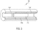
FIG. 3 is a partial isometric view of one embodiment of a coil assembly for use with the position sensor ofFIG. 1 . - Referring to the drawings,
FIG.1 shows ableed valve 100. In the illustrated embodiment, thebleed valve 100 includes avalve body 102, a valve disc 104, avalve shaft 106, apiston 110 and aposition sensor 130. In the illustrated embodiment, the bleedvalve 100 can be used to direct bleedair flow 101 to desired components and areas within an aircraft or other suitable vehicle.Bleed air flow 101 can often be high temperature and high pressure air flow, with temperatures ranging between 537.8°C - 760°C (1000F - 1400F) and pressures exceeding 6895 kPa (1000 psi). In the illustrated embodiment, theposition sensor 130 can determine a relative location of the valve disc 104 to determine the current state of operation of the bleedvalve 100 without being exposed to the harsh environment created by thebleed air flow 101. In certain embodiments,multiple bleed valves 100 can be utilized within a bleed airflow system to control bleedair flow 101 at various locations within the system.Bleed valves 100 can be controlled by a centralized controller. - In the illustrated embodiment, the valve disc 104 moves within the
valve body 102 to control thebleed air flow 101 through thevalve body 102. The valve disc 104 position controls the amount and flow of thebleed air flow 101 through thevalve body 102. The valve disc 104 can be a butterfly valve style disc that rotates within thevalve body 102 to control thebleed air flow 101. In the illustrated embodiment, the valve disc 104 is rotated by avalve shaft 106. In the illustrated embodiment, thevalve shaft 106 can rotate along thevalve shaft 106 axis to manipulate the position of the valve disc 104 relative to thevalve body 102. Thevalve shaft 106 can be rotated by any suitable actuator. - In the illustrated embodiment, the
valve shaft 106 is coupled to apiston 110 by apiston linkage 108. Thepiston 110 can be actuated by a hydraulic or pneumatic supply provided by theservo connection 114. In the illustrated embodiment, the movement of thepiston 110 is transferred to thevalve shaft 106 to convert the translational motion of thepiston 110 to rotational motion of thevalve shaft 106. Therefore, the movement of thepiston 110 can adjust the position of the valve disc 104. - In the illustrated embodiment, the
piston 110 can translate within a cavity formed by thevalve actuator cap 112. As shown inFIG. 1 , thevalve actuator cap 112 is spaced apart from the valve disc 104 and thebleed air flow 101. Therefore, in the illustrated embodiment, thevalve actuator cap 112 is subjected to a lower temperature environment than bleedair flow 101. - In the illustrated embodiment, the
position sensor 130 is disposed within thevalve actuator cap 112. In the illustrated embodiment, theposition sensor 130 includes the linear variable differential transformer (LVDT)assembly 140 and thecore assembly 150. In the illustrated embodiment, theposition sensor 130 is located away from the high pressure, high temperature bleedair flow 101 to allow for improved operation and reliability. - During operation of the bleed
valve 100, theposition sensor 130 can provide position feedback that can provide information regarding the operation conditions of the bleedvalve 100. In the illustrated embodiment, theposition sensor 130 is coupled to thepiston 110. Since the translation of thepiston 110 results in rotation of the valve disc 104, theposition sensor 130 can measure the translation of thepiston 110 and determine the rotation of the valve disc 104 without being exposed to thebleed air flow 101. - In the illustrated embodiment, the
position sensor 130 can convert the movement or position of thecore assembly 150 within theLVDT assembly 140 into a proportional electrical signal that can be received by a central controller. Advantageously, theposition sensor 130 utilizes electromagnetic coupling and does not require electrical contact between thecore assembly 150 and theLVDT assembly 140 to allow for enhanced reliability and sealing. During operation, alternating current drives theLVDT assembly 140 and as thecore assembly 150 changes position, the induced voltage within theLVDT assembly 140 changes, providing a position feedback signal. - Referring to
FIGS. 1 and2 , thecore assembly 150 is shown. In the illustrated embodiment, thecore assembly 150 includes acore 152, alink retainer 154, and aconnecting rod 156. In the illustrated embodiment, thecore 152 can translate within theLVDT assembly 140 to provide a signal corresponding to the position of the valve disc 104 since thelink retainer 154 is coupled to thepiston 110. In certain embodiments, the elements of thecore assembly 150 including thecore 152, thelink retainer 154 and the connectingrod 156 can be brazed together. In certain embodiments, the elements of thecore assembly 150 including thecore 152, thelink retainer 154 and the connectingrod 156 can be mechanically fastened by the use of threads, screws, rivets, or any other suitable mechanical fastening means. - In the illustrated embodiment, the
core 152 is a ferromagnetic core that translates within theLVDT assembly 140 to generate a feedback signal as previously described. Thecore 152 is sized to translate within theLVDT assembly 140 without contacting theLVDT assembly 140. In the illustrated embodiment, thecore 152 is coupled to a connectingrod 156 that also does not contact theLVDT assembly 140 and transfers the movement of thelink retainer 154. - In the illustrated embodiment, the
core assembly 150 is coupled to thepiston linkage 108 to translate thecore assembly 150 along with thepiston linkage 108. In the illustrated embodiment, thelink retainer 154 attaches to thepiston linkage 108 to allow a connection to thepiston linkage 108 without hindering the movement of thepiston 110, thepiston linkage 108, thevalve shaft 106 or the valve disc 104. In certain embodiments, retainingfeatures 155 of thelink retainer 154 can interface with various features of thepiston linkage 108 or thepiston 110 to attach to either thepiston linkage 108 or thepiston 110. In certain embodiments, thecore assembly 150 can be otherwise mechanically fastened to thepiston linkage 108 or thepiston 110 using a bolt or a nut. - Referring to
FIGS. 1 and3 , theLVDT assembly 140 is shown. In the illustrated embodiment, theLVDT assembly 140 includeselectrical connectors 142 andcoils 144. In certain embodiments, theLVDT assembly 140 can be threaded into thevalve actuator cap 112. In the illustrated embodiment, theelectrical connectors 142 are crimped connectors or mechanical connectors. - In the illustrated embodiment, the
coils 144 include aprimary coil 144a and asecondary coil 144b. In certain embodiments, thecoils 144a and 114b can be encapsulated in compacted ceramic powder to allow for greater heat resistance and resiliency. During operation of theLVDT assembly 140, an alternating current drives theprimary coil 144a and causes a voltage to be induced in thesecondary coil 144b. As thecore 152 moves, theprimary coil 144a causes the induced voltage in thesecondary coil 144b to change. In the illustrated embodiment, the output voltage of thesecondary coil 144b provides a differential voltage corresponding to the position of thecore 152. Therefore, the output voltage of thesecondary coil 144b can provide the position of the valve disc 104 without requiring theposition sensor 130 to be located within thebleed air flow 101. - The terminology used herein is for the purpose of describing particular embodiments only and is not intended to be limiting of the embodiments. While the description of the present embodiments has been presented for purposes of illustration and description, it is not intended to be exhaustive or limited to the embodiments in the form disclosed. Many modifications, variations, alterations, substitutions or equivalent arrangement not hereto described will be apparent to those of ordinary skill in the art without departing from the scope of the invention as defined by the claims. Additionally, while various embodiments have been described, it is to be understood that aspects may include only some of the described embodiments. Accordingly, the embodiments are not to be seen as limited by the foregoing description, but are only limited by the scope of the appended claims.
Claims (15)
- A position sensor for a bleed valve (100) with a piston (110), a valve disc (104), and a piston linkage (108) to couple the piston and the valve disc, the position sensor (130) comprising:a coil (144); anda core assembly (150), comprising:a core (152) disposed within the coil;a link retainer (154) coupled to the piston; anda connecting rod (156) coupled to the core and the link retainer.
- The position sensor of claim 1, wherein a core position of the core corresponds to a valve disc position of the valve disc (104).
- The position sensor of claim 1 or 2, wherein the core assembly is brazed.
- The position sensor of claim 1 or 2, wherein the core assembly is mechanically fastened.
- The position sensor of any preceding claim, the coil including at least one electrical connector (142).
- The position sensor of claim 5, wherein the at least one electrical connector is a crimped electrical connector.
- The position sensor of claim 5, wherein the at least one electrical connector is a mechanical electrical connector.
- The position sensor of any preceding claim, the coil including a primary coil (144a).
- The position sensor of any preceding claim, the coil including a secondary coil (144b).
- The position sensor of any preceding claim, wherein the coil is formed with a ceramic powder encapsulation.
- A bleed valve, comprising:a piston (110);a valve shaft (106);a piston linkage (108) to couple the piston and the valve shaft;a valve disc (104) coupled to the valve shaft; anda position sensor (130), comprising:a coil (144); anda core assembly (150), comprising:a core (152) disposed within the coil;a link retainer (154) coupled to the piston; anda connecting rod (156) coupled to the core and the link retainer.
- The bleed valve of claim 11, further comprising a valve actuator cap (112) disposed adjacent to the piston, wherein the coil is disposed within the valve actuator cap.
- The bleed valve of claim 11 or 12, wherein the core assembly is brazed.
- The bleed valve of claim 11 or 12, wherein the core assembly is mechanically fastened.
- The bleed valve of any of claims 11 to 14, the coil including at least one electrical connector.
Applications Claiming Priority (1)
| Application Number | Priority Date | Filing Date | Title |
|---|---|---|---|
| US15/009,290 US20170219118A1 (en) | 2016-01-28 | 2016-01-28 | Bleed valve position sensor |
Publications (1)
| Publication Number | Publication Date |
|---|---|
| EP3199850A1 true EP3199850A1 (en) | 2017-08-02 |
Family
ID=58191216
Family Applications (1)
| Application Number | Title | Priority Date | Filing Date |
|---|---|---|---|
| EP17153803.6A Withdrawn EP3199850A1 (en) | 2016-01-28 | 2017-01-30 | Bleed valve position sensor |
Country Status (4)
| Country | Link |
|---|---|
| US (1) | US20170219118A1 (en) |
| EP (1) | EP3199850A1 (en) |
| CN (1) | CN107061853A (en) |
| CA (1) | CA2955644A1 (en) |
Cited By (1)
| Publication number | Priority date | Publication date | Assignee | Title |
|---|---|---|---|---|
| FR3080430A1 (en) * | 2018-04-18 | 2019-10-25 | Safran Aircraft Engines | REGULATED OPEN-SIDED DISCHARGE VALVE |
Families Citing this family (6)
| Publication number | Priority date | Publication date | Assignee | Title |
|---|---|---|---|---|
| DE102017115671A1 (en) * | 2017-07-12 | 2019-01-17 | Rolls-Royce Deutschland Ltd & Co Kg | Valve system for a fluid line system in an aircraft engine and method for operating a valve system for a fluid line system in an aircraft engine |
| CN107939661A (en) * | 2017-12-04 | 2018-04-20 | 西南石油大学 | A kind of pressure break pump hydraulic end running parameter real-time monitoring system |
| JP7142434B2 (en) * | 2017-12-26 | 2022-09-27 | ナブテスコ株式会社 | actuator |
| DE102018210704A1 (en) * | 2018-06-29 | 2020-01-02 | Robert Bosch Gmbh | transducer |
| CN112178256A (en) * | 2020-09-29 | 2021-01-05 | 中国航发动力股份有限公司 | Large-size stable-speed anti-surge air release valve |
| CN116379037A (en) * | 2022-12-31 | 2023-07-04 | 中联重科股份有限公司 | Telescopic cylinders and construction machinery |
Citations (3)
| Publication number | Priority date | Publication date | Assignee | Title |
|---|---|---|---|---|
| US3654549A (en) * | 1967-12-30 | 1972-04-04 | Maurer & Co | Apparatus for inductively monitoring the movement of a piston within a cylinder of an injection molding machine |
| US20070102049A1 (en) * | 2005-11-09 | 2007-05-10 | Honeywell International, Inc. | Valve actuator assembly |
| US20080178665A1 (en) * | 2007-01-29 | 2008-07-31 | Hispano Suiza | Device for measuring the position of a piston in a cylinder |
Family Cites Families (14)
| Publication number | Priority date | Publication date | Assignee | Title |
|---|---|---|---|---|
| US3037484A (en) * | 1958-11-24 | 1962-06-05 | Telecomputing Corp | Remotely controlled actuator |
| US4815285A (en) * | 1987-03-09 | 1989-03-28 | Engineered Air Systems, Inc. | Gas turbine engine bleed control system |
| US5469053A (en) * | 1992-11-02 | 1995-11-21 | A - Tech Corporation | E/U core linear variable differential transformer for precise displacement measurement |
| US6354327B1 (en) * | 2000-07-31 | 2002-03-12 | Virginia Valve Company | Automatic position-control valve assembly |
| US6684898B2 (en) * | 2001-09-27 | 2004-02-03 | Honeywell International Inc. | Dual actuator air turbine starter valve |
| GB0225118D0 (en) * | 2002-10-29 | 2002-12-11 | Honeywell Normalair Garrett | Providing an indication of the position of a valve member |
| DE102004002145B4 (en) * | 2004-01-15 | 2007-11-22 | Radioplan Gmbh | Method and device for adapting a radio network model to the conditions of a real radio network |
| JP4369292B2 (en) * | 2004-05-06 | 2009-11-18 | タイコ フローコントロールジャパン株式会社 | Emergency shut-off valve device |
| US7779811B1 (en) * | 2006-09-13 | 2010-08-24 | General Electric Company | Thermoelectrically cooled components for distributed electronics control system for gas turbine engines |
| DE102009007657A1 (en) * | 2009-02-05 | 2010-08-12 | Wabco Gmbh | Piston-cylinder arrangement with integrated measuring device |
| US8887529B2 (en) * | 2010-10-29 | 2014-11-18 | Corning Incorporated | Method and apparatus for cutting glass ribbon |
| US8572838B2 (en) * | 2011-03-02 | 2013-11-05 | Honeywell International Inc. | Methods for fabricating high temperature electromagnetic coil assemblies |
| US8776820B2 (en) * | 2011-12-08 | 2014-07-15 | Kidde Technologies, Inc. | High rate discharge (HRD) valve incorporating a collet sleeve release mechanism |
| RU2659628C1 (en) * | 2014-02-03 | 2018-07-03 | ДЭНИЕЛ МЕЖЕМЕНТ энд КОНТРОЛ, ИНК. | Safety valve with position indication |
-
2016
- 2016-01-28 US US15/009,290 patent/US20170219118A1/en not_active Abandoned
-
2017
- 2017-01-19 CA CA2955644A patent/CA2955644A1/en not_active Abandoned
- 2017-01-26 CN CN201710057046.0A patent/CN107061853A/en active Pending
- 2017-01-30 EP EP17153803.6A patent/EP3199850A1/en not_active Withdrawn
Patent Citations (3)
| Publication number | Priority date | Publication date | Assignee | Title |
|---|---|---|---|---|
| US3654549A (en) * | 1967-12-30 | 1972-04-04 | Maurer & Co | Apparatus for inductively monitoring the movement of a piston within a cylinder of an injection molding machine |
| US20070102049A1 (en) * | 2005-11-09 | 2007-05-10 | Honeywell International, Inc. | Valve actuator assembly |
| US20080178665A1 (en) * | 2007-01-29 | 2008-07-31 | Hispano Suiza | Device for measuring the position of a piston in a cylinder |
Cited By (1)
| Publication number | Priority date | Publication date | Assignee | Title |
|---|---|---|---|---|
| FR3080430A1 (en) * | 2018-04-18 | 2019-10-25 | Safran Aircraft Engines | REGULATED OPEN-SIDED DISCHARGE VALVE |
Also Published As
| Publication number | Publication date |
|---|---|
| CA2955644A1 (en) | 2017-07-28 |
| US20170219118A1 (en) | 2017-08-03 |
| CN107061853A (en) | 2017-08-18 |
Similar Documents
| Publication | Publication Date | Title |
|---|---|---|
| EP3199850A1 (en) | Bleed valve position sensor | |
| US11953118B2 (en) | Sensors for valve systems, valve systems including sensors and related methods | |
| CN106660539B (en) | Electro-pneumatic regulating valve | |
| CN107923552B (en) | Rotary Actuated Valve with Position Indicator | |
| CN110103930A (en) | Sensor unit | |
| US4304264A (en) | Solenoid actuated valve | |
| EP2971639B1 (en) | A wastegate valve and turbocharger having same | |
| CN106164623A (en) | For detecting the system of sensor and the machinery disconnection of controlled member | |
| CN101900152A (en) | Method for electronically determining the wear state of a valve system and valve system | |
| EP1966496A2 (en) | Wireless position feedback device and system | |
| CN106090266B (en) | A kind of air gap control method of solenoid valve and the solenoid valve | |
| EP3358578B1 (en) | Displacement sensor | |
| CN103443496B (en) | The device of the improvement of on off state monitoring is carried out for break of exerting pressure to spring | |
| US8123191B2 (en) | Mechanical override | |
| EP3403012B1 (en) | Actuator and method for valve type recognition | |
| US7537022B2 (en) | Valve actuator assembly | |
| CN103195585A (en) | Anti-surge valve | |
| BR102017001661A2 (en) | POSITION SENSOR FOR BLOOD VALVE, AND, BLOOD VALVE | |
| CN107830232B (en) | Valve attachment, valve and method for controlling a valve | |
| EP4030593A1 (en) | Lvdt with integrated anti-rotation | |
| CN103883792B (en) | Valve actuator | |
| CN200985931Y (en) | Pneumatic power executor locater | |
| US9852834B2 (en) | Adjustable center pole | |
| DiFranco | Advances in Valve Position Monitoring |
Legal Events
| Date | Code | Title | Description |
|---|---|---|---|
| PUAI | Public reference made under article 153(3) epc to a published international application that has entered the european phase |
Free format text: ORIGINAL CODE: 0009012 |
|
| STAA | Information on the status of an ep patent application or granted ep patent |
Free format text: STATUS: THE APPLICATION HAS BEEN PUBLISHED |
|
| AK | Designated contracting states |
Kind code of ref document: A1 Designated state(s): AL AT BE BG CH CY CZ DE DK EE ES FI FR GB GR HR HU IE IS IT LI LT LU LV MC MK MT NL NO PL PT RO RS SE SI SK SM TR |
|
| AX | Request for extension of the european patent |
Extension state: BA ME |
|
| STAA | Information on the status of an ep patent application or granted ep patent |
Free format text: STATUS: REQUEST FOR EXAMINATION WAS MADE |
|
| 17P | Request for examination filed |
Effective date: 20180202 |
|
| RBV | Designated contracting states (corrected) |
Designated state(s): AL AT BE BG CH CY CZ DE DK EE ES FI FR GB GR HR HU IE IS IT LI LT LU LV MC MK MT NL NO PL PT RO RS SE SI SK SM TR |
|
| STAA | Information on the status of an ep patent application or granted ep patent |
Free format text: STATUS: EXAMINATION IS IN PROGRESS |
|
| 17Q | First examination report despatched |
Effective date: 20180618 |
|
| STAA | Information on the status of an ep patent application or granted ep patent |
Free format text: STATUS: THE APPLICATION IS DEEMED TO BE WITHDRAWN |
|
| 18D | Application deemed to be withdrawn |
Effective date: 20181030 |