EP3199837A1 - Gear baffle configured with lubricant outlet passage - Google Patents
Gear baffle configured with lubricant outlet passage Download PDFInfo
- Publication number
- EP3199837A1 EP3199837A1 EP16199972.7A EP16199972A EP3199837A1 EP 3199837 A1 EP3199837 A1 EP 3199837A1 EP 16199972 A EP16199972 A EP 16199972A EP 3199837 A1 EP3199837 A1 EP 3199837A1
- Authority
- EP
- European Patent Office
- Prior art keywords
- baffle
- bevel gear
- gear
- transmission system
- gear teeth
- Prior art date
- Legal status (The legal status is an assumption and is not a legal conclusion. Google has not performed a legal analysis and makes no representation as to the accuracy of the status listed.)
- Granted
Links
Images





Classifications
-
- F—MECHANICAL ENGINEERING; LIGHTING; HEATING; WEAPONS; BLASTING
- F16—ENGINEERING ELEMENTS AND UNITS; GENERAL MEASURES FOR PRODUCING AND MAINTAINING EFFECTIVE FUNCTIONING OF MACHINES OR INSTALLATIONS; THERMAL INSULATION IN GENERAL
- F16H—GEARING
- F16H57/00—General details of gearing
- F16H57/04—Features relating to lubrication or cooling or heating
- F16H57/042—Guidance of lubricant
- F16H57/0421—Guidance of lubricant on or within the casing, e.g. shields or baffles for collecting lubricant, tubes, pipes, grooves, channels or the like
-
- F—MECHANICAL ENGINEERING; LIGHTING; HEATING; WEAPONS; BLASTING
- F02—COMBUSTION ENGINES; HOT-GAS OR COMBUSTION-PRODUCT ENGINE PLANTS
- F02C—GAS-TURBINE PLANTS; AIR INTAKES FOR JET-PROPULSION PLANTS; CONTROLLING FUEL SUPPLY IN AIR-BREATHING JET-PROPULSION PLANTS
- F02C7/00—Features, components parts, details or accessories, not provided for in, or of interest apart form groups F02C1/00 - F02C6/00; Air intakes for jet-propulsion plants
- F02C7/32—Arrangement, mounting, or driving, of auxiliaries
-
- F—MECHANICAL ENGINEERING; LIGHTING; HEATING; WEAPONS; BLASTING
- F16—ENGINEERING ELEMENTS AND UNITS; GENERAL MEASURES FOR PRODUCING AND MAINTAINING EFFECTIVE FUNCTIONING OF MACHINES OR INSTALLATIONS; THERMAL INSULATION IN GENERAL
- F16H—GEARING
- F16H57/00—General details of gearing
- F16H57/04—Features relating to lubrication or cooling or heating
- F16H57/042—Guidance of lubricant
- F16H57/0421—Guidance of lubricant on or within the casing, e.g. shields or baffles for collecting lubricant, tubes, pipes, grooves, channels or the like
- F16H57/0423—Lubricant guiding means mounted or supported on the casing, e.g. shields or baffles for collecting lubricant, tubes or pipes
-
- F—MECHANICAL ENGINEERING; LIGHTING; HEATING; WEAPONS; BLASTING
- F16—ENGINEERING ELEMENTS AND UNITS; GENERAL MEASURES FOR PRODUCING AND MAINTAINING EFFECTIVE FUNCTIONING OF MACHINES OR INSTALLATIONS; THERMAL INSULATION IN GENERAL
- F16H—GEARING
- F16H57/00—General details of gearing
- F16H57/04—Features relating to lubrication or cooling or heating
- F16H57/048—Type of gearings to be lubricated, cooled or heated
- F16H57/0493—Gearings with spur or bevel gears
- F16H57/0495—Gearings with spur or bevel gears with fixed gear ratio
-
- F—MECHANICAL ENGINEERING; LIGHTING; HEATING; WEAPONS; BLASTING
- F05—INDEXING SCHEMES RELATING TO ENGINES OR PUMPS IN VARIOUS SUBCLASSES OF CLASSES F01-F04
- F05D—INDEXING SCHEME FOR ASPECTS RELATING TO NON-POSITIVE-DISPLACEMENT MACHINES OR ENGINES, GAS-TURBINES OR JET-PROPULSION PLANTS
- F05D2260/00—Function
- F05D2260/40—Transmission of power
- F05D2260/403—Transmission of power through the shape of the drive components
- F05D2260/4031—Transmission of power through the shape of the drive components as in toothed gearing
-
- F—MECHANICAL ENGINEERING; LIGHTING; HEATING; WEAPONS; BLASTING
- F05—INDEXING SCHEMES RELATING TO ENGINES OR PUMPS IN VARIOUS SUBCLASSES OF CLASSES F01-F04
- F05D—INDEXING SCHEME FOR ASPECTS RELATING TO NON-POSITIVE-DISPLACEMENT MACHINES OR ENGINES, GAS-TURBINES OR JET-PROPULSION PLANTS
- F05D2260/00—Function
- F05D2260/50—Kinematic linkage, i.e. transmission of position
- F05D2260/53—Kinematic linkage, i.e. transmission of position using gears
- F05D2260/532—Kinematic linkage, i.e. transmission of position using gears of the bevelled or angled type
-
- F—MECHANICAL ENGINEERING; LIGHTING; HEATING; WEAPONS; BLASTING
- F05—INDEXING SCHEMES RELATING TO ENGINES OR PUMPS IN VARIOUS SUBCLASSES OF CLASSES F01-F04
- F05D—INDEXING SCHEME FOR ASPECTS RELATING TO NON-POSITIVE-DISPLACEMENT MACHINES OR ENGINES, GAS-TURBINES OR JET-PROPULSION PLANTS
- F05D2260/00—Function
- F05D2260/98—Lubrication
Definitions
- This disclosure relates generally to a transmission system and, more particularly, to a baffle for a set of meshing gears such as, for example, meshing bevel gears in a turbine engine.
- a turbine engine may include a transmission system for coupling one of its spools to an accessory gearbox.
- This transmission system may include a bull gear mounted to a shaft of the spool.
- the transmission system also includes a tower shaft and an associated bevel gear mounted to a first end of the tower shaft, where a second end of the tower shaft is coupled to the accessory gearbox.
- the transmission system may also include a baffle configured to cover at least a portion of the bevel gear (or the bull gear).
- Such a baffle is provided so as to prevent surplus lubricant, churning within a compartment in which the transmission system is located, from impinging on that portion of the bevel gear (or the bull gear) since such surplus lubricant impingement may increase windage (e.g., fluid drag) on the bevel gear (or the bull gear).
- a baffle may also capture lubricant which is propelled off of the bevel gear. This captured lubricant may chum within the space between the bevel gear and the baffle and thereby cause windage on the bevel gear.
- a transmission system includes a first bevel gear, a second bevel gear and a baffle.
- the second bevel gear is meshed with the first bevel gear.
- the second bevel gear includes a plurality of gear teeth arranged in a circumferential array.
- the baffle includes a baffle wall and a baffle outlet.
- the baffle wall is arranged next to and covers a subset of the gear teeth.
- the baffle outlet forms a lubricant outlet passage that extends through the baffle wall.
- a transmission system within a compartment.
- the transmission system includes a first bevel gear, a second bevel gear and a baffle.
- the second bevel gear includes a plurality of gear teeth arranged in a circumferential array. A first subset of the gear teeth within a first region are meshed with the first bevel gear. A second subset of the gear teeth within a second region are disengaged from the first bevel gear.
- the baffle includes a baffle wall and a baffle outlet.
- the baffle wall is configured to substantially prevent the second subset of the gear teeth in the second region from receiving lubricant particles moving within the compartment.
- the baffle outlet forms a lubricant outlet passage that extends through the baffle wall.
- the lubricant outlet passage is configured to receive lubricant propelled off of the second bevel gear.
- a turbine engine includes a turbine engine spool, a tower shaft, a bearing compartment and a transmission system.
- the transmission system is located within the bearing compartment.
- the transmission system includes a pair of bevel gears and a baffle.
- a first of the bevel gears is connected to the turbine engine spool.
- a second of the bevel gears is connected to the tower shaft.
- One of the bevel gears (e.g., the first or second bevel gear) includes a plurality of gear teeth arranged in a circumferential array.
- a first subset of the gear teeth within a first region are meshed with another one of the bevel gears (e.g., the second or first bevel gear).
- a second subset of the gear teeth within a second region are disengaged from the other one of the bevel gears.
- the baffle includes a baffle wall and a baffle outlet.
- the baffle wall covers the second subset of the gear teeth in the second region.
- the baffle outlet forms a lubricant outlet passage that extends through the baffle wall.
- the baffle wall may cover the second subset of the gear teeth in the second region.
- the baffle outlet may include an orifice and an orifice cover.
- the orifice may extend through the baffle wall and/or may form a first portion of the lubricant outlet passage.
- the orifice cover may overlap the orifice.
- the orifice cover may be connected to the baffle wall.
- the orifice cover may form a second portion of the lubricant outlet passage with the baffle wall.
- the subset of the gear teeth may be disengaged from the first bevel gear. Another subset of the gear teeth may be meshed with the first bevel gear.
- the baffle outlet may be located proximate the other subset of the gear teeth.
- the subset of the gear teeth may define a radial outer peripheral region of the second bevel gear which extends circumferentially around a rotational axis of the second bevel gear more than about 4.7 radians.
- the subset of the gear teeth may define a radial outer peripheral region of the second bevel gear which extends circumferentially around a rotational axis of the second bevel gear between about 3.3 radians and about 5.3 radians.
- the baffle wall may be configured to substantially prevent the subset of the gear teeth from receiving lubricant.
- the baffle wall may form a baffle channel.
- the subset of the gear teeth may extend into the baffle channel.
- the baffle channel may extend circumferentially around a rotational axis of the second bevel gear between a first channel end and a second channel end.
- the first channel end may be disposed forward of the second channel end relative to rotation of the second bevel gear about the rotational axis.
- the baffle outlet may be arranged at the first channel end.
- the baffle outlet may include an orifice and an orifice cover.
- the orifice may extend through the baffle wall, and may form a first portion of the lubricant outlet passage.
- the orifice cover may overlap the orifice.
- the orifice cover may be connected to the baffle wall.
- the orifice cover may form a second portion of the lubricant outlet passage with the baffle wall.
- the orifice cover may project circumferentially beyond the orifice.
- the orifice may have a polygonal cross-sectional geometry.
- the orifice may have a first circumferential width at a first location and a second circumferential width at a second location.
- the first circumferential width may be less than or greater than the second circumferential width.
- the first location may be radially closer to a rotational axis of the second bevel gear than the second location.
- the baffle outlet may be formed by a double walled portion of the baffle.
- the baffle may include a window. A portion of the second bevel gear may extend radially out through the window. The portion of the second bevel gear may mesh with the first bevel gear. Alternatively, a portion of the first bevel gear may extend radially out through the window. The portion of the first bevel gear may mesh with the second bevel gear.
- the baffle may include a second baffle outlet which forms a second lubricant outlet passage that extends through the baffle wall.
- a turbine engine spool and a tower shaft may be included.
- the first bevel gear may be connected to the turbine engine spool.
- the second bevel gear may be connected to the tower shaft.
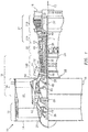
- FIG. 1 is a side cutaway illustration of a geared turbine engine 10, which is configured as a turbofan engine for an aircraft propulsion system.
- This turbine engine 10 extends along an axial centerline 12 between an upstream airflow inlet 14 and a downstream airflow exhaust 16.
- the turbine engine 10 includes a fan section 18, a compressor section 19, a combustor section 20 and a turbine section 21.
- the compressor section 19 includes a low pressure compressor (LPC) section 19A and a high pressure compressor (HPC) section 19B.
- the turbine section 21 includes a high pressure turbine (HPT) section 21A and a low pressure turbine (LPT) section 21B.
- the engine sections 18-21 are arranged sequentially along the centerline 12 within an engine housing 22.
- This housing 22 includes an inner case 24 (e.g., a core case) and an outer case 26 (e.g., a fan case).
- the inner case 24 may house one or more of the engine sections 19-21; e.g., an engine core.
- the outer case 26 may house at least the fan section 18.
- Each of the engine sections 18, 19A, 19B, 21A and 21B includes a respective rotor 28-32.
- Each of these rotors 28-32 includes a plurality of rotor blades arranged circumferentially around and connected to one or more respective rotor disks.
- the rotor blades may be formed integral with or mechanically fastened, welded, brazed, adhered and/or otherwise attached to the respective rotor disk(s).
- the fan rotor 28 is connected to a gear train 34, for example, through a fan shaft 36.
- the gear train 34 and the LPC rotor 29 are connected to and driven by the LPT rotor 32 through a low speed shaft 37.
- the combination of at least the LPC rotor 29, the LPT rotor 32 and low speed shaft 37 may be referred to as "a low speed spool”.
- the HPC rotor 30 is connected to and driven by the HPT rotor 31 through a high speed shaft 38.
- the combination of at least the HPC rotor 30, the HPT rotor 31 and high speed shaft 38 may be referred to as "a high speed spool".
- the shafts 36-38 are rotatably supported by a plurality of bearings 40; e.g., rolling element and/or thrust bearings.
- bearings 40 e.g., rolling element and/or thrust bearings.
- Each of these bearings 40 is connected to the engine housing 22 by at least one stationary structure such as, for example, an annular support strut.
- the core gas path 42 flows sequentially through the engine sections 19-21.
- the air within the core gas path 42 may be referred to as "core air”.
- the bypass gas path 44 flows through a duct between the inner case 24 and the outer case 26.
- the air within the bypass gas path 44 may be referred to as "bypass air”.
- the core air is compressed by the compressor rotors 29 and 30 and directed into a combustion chamber 46 of a combustor 48 in the combustor section 20.
- Fuel is injected into the combustion chamber 46 and mixed with the compressed core air to provide a fuel-air mixture.
- This fuel air mixture is ignited and combustion products thereof expand and flow through and sequentially cause the turbine rotors 31 and 32 to rotate.
- the rotation of the turbine rotors 31 and 32 respectively drive rotation of the compressor rotors 30 and 29 and, thus, compression of the air received from the core airflow inlet 14.
- the rotation of the turbine rotor 32 also drives rotation of the fan rotor 28, which propels bypass air through and out of the bypass gas path 44.
- the propulsion of the bypass air may account for a majority of thrust generated by the turbine engine 10, e.g., more than seventy-five percent (75%) of engine thrust.
- the turbine engine 10 of the present disclosure is not limited to the foregoing exemplary thrust ratio.
- the turbine engine 10 of FIG. 1 also includes an accessory gearbox 50, one or more gearbox attachments 52 and a transmission system 54.
- the accessory gearbox 50 is mounted to the inner case 24. However, in alternative embodiments, the accessory gearbox 50 may be mounted elsewhere with the turbine engine 10; e.g., to the outer case 26.
- the accessory gearbox 50 is configured to transfer rotational energy (e.g., torque) between the transmission system 54 and the one or more gearbox attachments 52.
- An example of an accessory gearbox is disclosed in U.S. Patent No. 9,068,515 to Duong et al.
- Examples of a gearbox attachment may include an air turbine starter, a deoiler, a hydraulic pump, an oil pump, an integrated drive generator, a permanent magnet alternator and a fuel pump module.
- the present disclosure is not limited to including the foregoing exemplary types or configurations of the accessory gearbox 50 or the gearbox attachments 52.
- the transmission system 54 is configured to mechanically couple and thereby transfer rotational energy (e.g., torque) between a rotating assembly (or component) of the turbine engine 10 and the accessory gearbox 50.
- the transmission system 54 of FIG. 1 mechanically couples one of the spools of the turbine engine 10 (e.g., via the high speed spool) with the accessory gearbox 50.
- This transmission system 54 includes the high speed shaft 38, a tower shaft 56 and a geared system 58.
- the geared system 58 includes a first gear 60, a second gear 62 and a baffle 64.
- the first gear 60 of FIG. 2 is configured as a bevel gear and, in particular, as a bull bevel gear.
- This first gear 60 is mounted to the high speed shaft 38, for example, by a splined interface (e.g., see FIG. 3 ).
- the first gear 60 has a first rotational axis 66, which is coaxial with a rotational axis 68 of the low speed shaft 37; e.g., the centerline 12.
- the first gear 60 includes a plurality of first gear teeth 70. These first gear teeth 70 are arranged in a circumferential array, which extends circumferentially around the first rotational axis 66.
- the first gear teeth 70 of FIG. 3 are configured to provide the first gear 60 with an annular, conically shaped pitch surface.
- the term "pitch surface” may describe an imaginary toothless surface formed by averaging out peaks and valleys of the first gear teeth 70.
- the first gear teeth 70 of FIG. 3 are further configured to provide the first gear 60 with a spiral (or helical) bevel gear configuration.
- the first gear teeth 70 may be configured to provide the first gear 60 with a straight bevel gear configuration, a Zerol bevel gear configuration, a hypoid bevel gear configuration or a double spiral (or helical) bevel gear configuration.
- the present disclosure is not limited to the foregoing exemplary first gear types or configurations.
- the second gear 62 of FIG. 2 is also configured as a bevel gear.
- This second gear 62 is mounted to the tower shaft 56, for example, by a splined interface.
- the second gear 62 has a second rotational axis 72, which is coaxial with a rotational axis 74 of the tower shaft 56.
- This second rotational axis 72 is arranged coincident with and at least generally (e.g., within +/- one or two degrees) perpendicular to the first rotational axis 66.
- the second rotational axis 72 may be arranged coincident with and acutely or obtusely angled to the first rotational axis 66.
- the second gear 62 includes a plurality of second gear teeth 76. These second gear teeth 76 are arranged in a circumferential array, which extends circumferentially around the second rotational axis 72.
- the second gear teeth 76 of FIG. 3 are configured to provide the second gear 62 with an annular, conically shaped pitch surface.
- the second gear teeth 76 of FIG. 3 are further configured to provide the second gear 62 with a spiral (or helical) bevel gear configuration.
- the second gear teeth 76 may be configured to provide the second gear 62 with a straight bevel gear configuration, a Zerol bevel gear configuration, a hypoid bevel gear configuration or a double spiral (or helical) bevel gear configuration.
- the present disclosure is not limited to the foregoing exemplary second gear types or configurations.
- the second gear 62 is meshed (e.g., mated and engaged) with the first gear 60.
- a first subset 78 e.g., meshed subarray
- a first subset 80 e.g., meshed subarray
- each of these subsets 78, 80 includes one or more of the respective gear teeth 70, 76.
- a second subset 82 (e.g., unmeshed subarray) of the first gear teeth 70 (e.g., the remaining first gear teeth) are unmeshed and disengaged from a second subset 84 (e.g., unmeshed subarray) of the second gear teeth 76 (e.g., the remaining second gear teeth), where each of these subsets 82, 84 includes a plurality - e.g., here the majority - of the respective gear teeth 70, 76.
- the specific gear teeth in each subset will change as the respective gear rotates about its respective rotational axis.
- the baffle 64 is arranged with (e.g., positioned next to and in close proximity with) the second gear 62 so as to cover a region of the second gear 62 as described below in further detail.
- the baffle 64 is connected to a stationary structure (see FIG. 2 ; e.g., generally the housing 22) and thereby remains stationary as the second gear 62 rotates about its rotational axis 72.
- the baffle 64 includes a baffle wall 86 and a baffle outlet 88.
- the baffle wall 86 is configured to cover the second subset 84 of the second gear teeth 76.
- the baffle wall 86 may not cover the first subset 80 of the second gear teeth 76; i.e., leaves the first subset 80 uncovered and exposed.
- the baffle wall 86 is operable to enable a lubricant system (not shown) to direct lubricant (e.g., oil) onto the first and/or the second gear teeth 70, 76 just prior to and/or at a region where those gear teeth mesh with one another (see FIG. 3 ).
- the baffle wall 86 may be operable to substantially prevent the unmeshed / disengaged second gear teeth 76 (e.g., the second subset 84 of the second gear teeth) from being impinged by or otherwise receiving additional lubricant; e.g., lubricant particles churning or otherwise moving around a compartment 90 (e.g., bearing compartment) in which the transmission system 54 is located; see FIG. 2 .
- additional lubricant if allowed to impinge on the unmeshed / disengaged second gear teeth 76, may increase second gear 62 windage and thereby decrease efficiency of the transmission system 54 and, thus, the turbine engine 10.
- the baffle wall 86 is configured as a segmented circular body.
- This baffle wall 86 includes a radial outer peripheral portion 92 and a radial interior portion 94.
- the peripheral portion 92 may have a generally segmented annular geometry.
- the peripheral portion 92 extends circumferentially around the second rotational axis 72 so as to form, for example, a full hoop.
- the peripheral portion 92 is configured to also form a window 96 (see also FIGS. 6 and 7 ) at the segmented portion of the baffle wall 86.
- This window 96 is sized and shaped such that a portion (e.g., a minor segment) of the second gear 62 may extend radially through the window 96 and mesh with the first gear 60 as described above.
- the window 96 is also sized and shaped to enable the lubricant system to direct the lubricant onto the first and/or the second gear teeth 70, 76.
- the peripheral portion 92 is further configured to form an arcuate baffle channel 98; e.g., a lubricant gutter.
- This baffle channel 98 extends circumferentially around the second rotational axis 72 between a first channel end 100 and a second channel end 102 (see FIG. 6 ), where the first channel end 100 may be located forward of the second channel end 102 when viewed relative to the rotation of the second gear 62.
- This channel 98 may have a generally u-shape cross-sectional geometry as shown in FIG. 5 ; however, the present disclosure is not limited to such an exemplary embodiment.
- the channel 98 is sized and the peripheral portion 92 of the baffle wall 86 is configured such that the second gear 62 extends axially and/or radially into the channel 98. More particularly, the second subset 84 of the second gear teeth 76 project into the channel 98 such that, for example, the peripheral portion 92 wraps partially around those gear teeth 76.
- the peripheral portion 92 of the baffle wall 86 thereby covers a radial outer peripheral region of the second gear 62. In the exemplary embodiment of FIG. 4 , this peripheral region may extend between about 3.3 and about 5.3 radians around the second rotational axis 72 (e.g., approximately between the ends 100 and 102; see FIG. 6 ); however, the present disclosure is not limited to such an exemplary embodiment.
- the peripheral portion 92 covers at least some or substantially all of the unmeshed / disengaged second gear teeth 76 and substantially prevents those second gear teeth 76 from receiving additional lubricant moving within the compartment 90.
- the interior portion 94 of the baffle wall 86 may be configured to substantially plug an inner bore formed by the peripheral portion 92.
- the interior portion 94 may include one or more apertures such as through-holes (not shown).
- the second gear 62 may propel lubricant (used for lubricating the meshing between the gears 60 and 62) off of the second gear teeth 76 at a region approximately where those second gear teeth 76 disengage from the first gear teeth 70.
- the baffle outlet 88 is configured to form a lubricant outlet passage 104 through the baffle wall 86. Referring to FIGS. 5-7 , this lubricant outlet passage 104 fluidly couples the channel 98 with a portion of the compartment 90 external of the baffle 64. The baffle outlet 88 is thereby configured to direct the used lubricant out of the channel 98 and away from the baffle 64 through the lubricant outlet passage 104.
- the baffle outlet 88 may be located generally at (e.g., on, adjacent or proximate) the first channel end 100.
- the baffle outlet 88 may be located within 3 radians of the first subset 80 of the second gear teeth 76. In this manner, the baffle outlet 88 may direct the majority of the used lubricant away from the second gear teeth 76 while also reducing the area that the used lubricant can chum within the channel 98 before being removed. This in turn may reduce windage on the second gear teeth 76 and, thereby, further increase transmission system 54 efficiency. Note, if the baffle 64 was configured without the baffle outlet 88, the used lubricant would be generally trapped within the channel 98 and would increase windage on the second gear teeth 76.
- the baffle outlet 88 may be configured as a double wall portion of the baffle 64.
- the baffle outlet 88 of FIGS. 5-7 includes an orifice 106 and an orifice cover 108.
- the orifice 106 extends through the baffle wall 86 (e.g., the peripheral portion 92).
- the orifice 106 forms a first (upstream) portion of the lubricant outlet passage 104.
- the orifice 106 of FIGS. 5-7 has a polygonal (e.g., triangular) cross-sectional geometry.
- This orifice 106 has a first circumferential width at a first location 110 and a second circumferential width at a second location 112, where the first location 110 is radially closer to second rotational axis 72 than the second location 112.
- the first circumferential width may be greater than the second circumferential width.
- the first circumferential width may be less than the second circumferential width; note, such an alternative orifice 106 configuration is applicable to each of the baffle 64 embodiments disclosed herein.
- the orifice 106 may be formed by an array of apertures; e.g., a porous portion of the baffle wall 86.
- the orifice cover 108 is configured to at least (e.g., circumferentially and/or radially) overlap the orifice 106.
- the orifice cover 108 further projects circumferentially beyond the orifice 106 thereby overlapping the baffle wall 86.
- the orifice cover 108 is connected to the baffle wall 86.
- the orifice cover 108 may be formed integral with or otherwise attached to the baffle wall 86 at opposing sides of the orifice 106 as well as at an upstream end of the orifice 106 as best seen in FIG. 7 .
- the orifice cover 108 forms a second (downstream) portion of the lubricant outlet passage 104 with the baffle wall 86 and, more particularly, the peripheral portion 92.
- the lubricant outlet passage 104 is operable to direct used lubricant away from the second gear 62 as well as reduce the likelihood of other lubricant surrounding the baffle 64 from flowing in an opposite direction through the lubricant outlet passage 104 and impinging on the second gear teeth 76.
- the baffle 64 may also (or alternatively) include a second baffle outlet 114.
- This baffle outlet 114 may be configured as a notch or aperture in the baffle wall 86 without a covering thereover.
- the second baffle outlet 114 may be configured similar to the baffle outlet 88 described above, but positioned at another circumferential location along the baffle wall 86.
- the baffle wall 86 may be configured as a segmented annular body.
- the baffle wall 86 may be configured without some or all of the interior portion 94 (see FIG. 4 ); e.g., with an inner bore 116.
- the baffle 64 may be configured with the first gear 60 rather than the second gear 62.
- an additional baffle may be included. This additional baffle may be configured similar to the baffle 64 described above and may be configured with the first gear 60 such that both gears 60 and 62 are configured with its own baffle.
- the transmission system 54 may be included in various turbine engines other than the one described above as well as in other types of rotational equipment; e.g., any system which utilizes lubricated bevel gears, for example.
- the transmission system 54 may be included in a geared turbine engine where a gear train connects one or more shafts to one or more rotors in a fan section, a compressor section and/or any other engine section.
- the transmission system 54 may be included in a turbine engine configured without a gear train.
- the transmission system 54 may be included in a geared or non-geared turbine engine configured with a single spool, with two spools (e.g., see FIG.
- the turbine engine may be configured as a turbofan engine, a turbojet engine, a propfan engine, a pusher fan engine or any other type of turbine engine.
- the present invention therefore is not limited to any particular types or configurations of turbine engines or rotational equipment.
Landscapes
- Engineering & Computer Science (AREA)
- General Engineering & Computer Science (AREA)
- Mechanical Engineering (AREA)
- Chemical & Material Sciences (AREA)
- Combustion & Propulsion (AREA)
- General Details Of Gearings (AREA)
Abstract
Description
- This disclosure relates generally to a transmission system and, more particularly, to a baffle for a set of meshing gears such as, for example, meshing bevel gears in a turbine engine.
- A turbine engine may include a transmission system for coupling one of its spools to an accessory gearbox. This transmission system may include a bull gear mounted to a shaft of the spool. The transmission system also includes a tower shaft and an associated bevel gear mounted to a first end of the tower shaft, where a second end of the tower shaft is coupled to the accessory gearbox. The transmission system may also include a baffle configured to cover at least a portion of the bevel gear (or the bull gear). Such a baffle is provided so as to prevent surplus lubricant, churning within a compartment in which the transmission system is located, from impinging on that portion of the bevel gear (or the bull gear) since such surplus lubricant impingement may increase windage (e.g., fluid drag) on the bevel gear (or the bull gear). However, such a baffle may also capture lubricant which is propelled off of the bevel gear. This captured lubricant may chum within the space between the bevel gear and the baffle and thereby cause windage on the bevel gear.
- There is a need in the art for an improved baffle which can further reduce lubricant related windage on a gear such as a bevel gear.
- According to an aspect of the present disclosure, a transmission system is provided that includes a first bevel gear, a second bevel gear and a baffle. The second bevel gear is meshed with the first bevel gear. The second bevel gear includes a plurality of gear teeth arranged in a circumferential array. The baffle includes a baffle wall and a baffle outlet. The baffle wall is arranged next to and covers a subset of the gear teeth. The baffle outlet forms a lubricant outlet passage that extends through the baffle wall.
- According to another aspect of the present disclosure, a transmission system is provided within a compartment. The transmission system includes a first bevel gear, a second bevel gear and a baffle. The second bevel gear includes a plurality of gear teeth arranged in a circumferential array. A first subset of the gear teeth within a first region are meshed with the first bevel gear. A second subset of the gear teeth within a second region are disengaged from the first bevel gear. The baffle includes a baffle wall and a baffle outlet. The baffle wall is configured to substantially prevent the second subset of the gear teeth in the second region from receiving lubricant particles moving within the compartment. The baffle outlet forms a lubricant outlet passage that extends through the baffle wall. The lubricant outlet passage is configured to receive lubricant propelled off of the second bevel gear.
- According to another aspect of the present disclosure, a turbine engine is provided that includes a turbine engine spool, a tower shaft, a bearing compartment and a transmission system. The transmission system is located within the bearing compartment. The transmission system includes a pair of bevel gears and a baffle. A first of the bevel gears is connected to the turbine engine spool. A second of the bevel gears is connected to the tower shaft. One of the bevel gears (e.g., the first or second bevel gear) includes a plurality of gear teeth arranged in a circumferential array. A first subset of the gear teeth within a first region are meshed with another one of the bevel gears (e.g., the second or first bevel gear). A second subset of the gear teeth within a second region are disengaged from the other one of the bevel gears. The baffle includes a baffle wall and a baffle outlet. The baffle wall covers the second subset of the gear teeth in the second region. The baffle outlet forms a lubricant outlet passage that extends through the baffle wall.
- The baffle wall may cover the second subset of the gear teeth in the second region.
- The baffle outlet may include an orifice and an orifice cover. The orifice may extend through the baffle wall and/or may form a first portion of the lubricant outlet passage. The orifice cover may overlap the orifice. The orifice cover may be connected to the baffle wall. The orifice cover may form a second portion of the lubricant outlet passage with the baffle wall.
- The subset of the gear teeth may be disengaged from the first bevel gear. Another subset of the gear teeth may be meshed with the first bevel gear.
- The baffle outlet may be located proximate the other subset of the gear teeth.
- The subset of the gear teeth may define a radial outer peripheral region of the second bevel gear which extends circumferentially around a rotational axis of the second bevel gear more than about 4.7 radians.
- The subset of the gear teeth may define a radial outer peripheral region of the second bevel gear which extends circumferentially around a rotational axis of the second bevel gear between about 3.3 radians and about 5.3 radians.
- The baffle wall may be configured to substantially prevent the subset of the gear teeth from receiving lubricant.
- The baffle wall may form a baffle channel. The subset of the gear teeth may extend into the baffle channel.
- The baffle channel may extend circumferentially around a rotational axis of the second bevel gear between a first channel end and a second channel end. The first channel end may be disposed forward of the second channel end relative to rotation of the second bevel gear about the rotational axis. The baffle outlet may be arranged at the first channel end.
- The baffle outlet may include an orifice and an orifice cover. The orifice may extend through the baffle wall, and may form a first portion of the lubricant outlet passage. The orifice cover may overlap the orifice. The orifice cover may be connected to the baffle wall. The orifice cover may form a second portion of the lubricant outlet passage with the baffle wall.
- The orifice cover may project circumferentially beyond the orifice.
- The orifice may have a polygonal cross-sectional geometry.
- The orifice may have a first circumferential width at a first location and a second circumferential width at a second location. The first circumferential width may be less than or greater than the second circumferential width. The first location may be radially closer to a rotational axis of the second bevel gear than the second location.
- The baffle outlet may be formed by a double walled portion of the baffle.
- The baffle may include a window. A portion of the second bevel gear may extend radially out through the window. The portion of the second bevel gear may mesh with the first bevel gear. Alternatively, a portion of the first bevel gear may extend radially out through the window. The portion of the first bevel gear may mesh with the second bevel gear.
- The baffle may include a second baffle outlet which forms a second lubricant outlet passage that extends through the baffle wall.
- A turbine engine spool and a tower shaft may be included. The first bevel gear may be connected to the turbine engine spool. The second bevel gear may be connected to the tower shaft.
- The foregoing features and the operation of the invention will become more apparent in light of the following description and the accompanying drawings.
-
-
FIG. 1 is a side cutaway illustration of a geared turbine engine. -
FIG. 2 is a side sectional schematic diagram of a transmission system. -
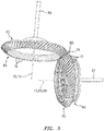
FIG. 3 is a perspective illustration of meshing gears and associated shafts for the transmission system. -
FIG. 4 is a perspective illustration of the transmission system. -
FIG. 5 is a perspective sectional illustration of a portion of a gear and a portion of an associated baffle for the transmission system. -
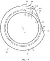
FIG. 6 is an illustration of an interior side of the baffle. -
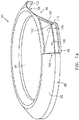
FIG. 7 is a perspective illustration of an exterior side of the baffle shown with a transparent wall for visualization purposes. -
FIG. 7B is a perspective illustration of an exterior side of an alternative baffle shown with a transparent wall for visualization purposes, which baffle is configured with a bevel gear. -
FIG. 8 is a perspective illustration of an exterior side of an alternative baffle. -
FIG. 9 is a perspective illustration of an exterior side of another alternative baffle shown with a transparent wall for visualization purposes. -
FIG. 1 is a side cutaway illustration of a gearedturbine engine 10, which is configured as a turbofan engine for an aircraft propulsion system. Thisturbine engine 10 extends along anaxial centerline 12 between anupstream airflow inlet 14 and adownstream airflow exhaust 16. - The
turbine engine 10 includes afan section 18, acompressor section 19, acombustor section 20 and aturbine section 21. Thecompressor section 19 includes a low pressure compressor (LPC)section 19A and a high pressure compressor (HPC)section 19B. Theturbine section 21 includes a high pressure turbine (HPT)section 21A and a low pressure turbine (LPT)section 21B. - The engine sections 18-21 are arranged sequentially along the
centerline 12 within anengine housing 22. Thishousing 22 includes an inner case 24 (e.g., a core case) and an outer case 26 (e.g., a fan case). Theinner case 24 may house one or more of the engine sections 19-21; e.g., an engine core. Theouter case 26 may house at least thefan section 18. - Each of the
engine sections - The
fan rotor 28 is connected to agear train 34, for example, through afan shaft 36. Thegear train 34 and theLPC rotor 29 are connected to and driven by theLPT rotor 32 through alow speed shaft 37. The combination of at least theLPC rotor 29, theLPT rotor 32 andlow speed shaft 37 may be referred to as "a low speed spool". TheHPC rotor 30 is connected to and driven by theHPT rotor 31 through ahigh speed shaft 38. The combination of at least theHPC rotor 30, theHPT rotor 31 andhigh speed shaft 38 may be referred to as "a high speed spool". The shafts 36-38 are rotatably supported by a plurality ofbearings 40; e.g., rolling element and/or thrust bearings. Each of thesebearings 40 is connected to theengine housing 22 by at least one stationary structure such as, for example, an annular support strut. - During operation, air enters the
turbine engine 10 through theairflow inlet 14. This air is directed through thefan section 18 and into acore gas path 42 and abypass gas path 44. Thecore gas path 42 flows sequentially through the engine sections 19-21. The air within thecore gas path 42 may be referred to as "core air". Thebypass gas path 44 flows through a duct between theinner case 24 and theouter case 26. The air within thebypass gas path 44 may be referred to as "bypass air". - The core air is compressed by the
compressor rotors combustion chamber 46 of acombustor 48 in thecombustor section 20. Fuel is injected into thecombustion chamber 46 and mixed with the compressed core air to provide a fuel-air mixture. This fuel air mixture is ignited and combustion products thereof expand and flow through and sequentially cause theturbine rotors turbine rotors compressor rotors core airflow inlet 14. The rotation of theturbine rotor 32 also drives rotation of thefan rotor 28, which propels bypass air through and out of thebypass gas path 44. The propulsion of the bypass air may account for a majority of thrust generated by theturbine engine 10, e.g., more than seventy-five percent (75%) of engine thrust. Theturbine engine 10 of the present disclosure, however, is not limited to the foregoing exemplary thrust ratio. - The
turbine engine 10 ofFIG. 1 also includes anaccessory gearbox 50, one ormore gearbox attachments 52 and atransmission system 54. Theaccessory gearbox 50 is mounted to theinner case 24. However, in alternative embodiments, theaccessory gearbox 50 may be mounted elsewhere with theturbine engine 10; e.g., to theouter case 26. Theaccessory gearbox 50 is configured to transfer rotational energy (e.g., torque) between thetransmission system 54 and the one ormore gearbox attachments 52. An example of an accessory gearbox is disclosed inU.S. Patent No. 9,068,515 to Duong et al. accessory gearbox 50 or thegearbox attachments 52. - The
transmission system 54 is configured to mechanically couple and thereby transfer rotational energy (e.g., torque) between a rotating assembly (or component) of theturbine engine 10 and theaccessory gearbox 50. In particular, thetransmission system 54 ofFIG. 1 mechanically couples one of the spools of the turbine engine 10 (e.g., via the high speed spool) with theaccessory gearbox 50. Thistransmission system 54 includes thehigh speed shaft 38, atower shaft 56 and a gearedsystem 58. Referring toFIG. 2 , the gearedsystem 58 includes afirst gear 60, asecond gear 62 and abaffle 64. - The
first gear 60 ofFIG. 2 is configured as a bevel gear and, in particular, as a bull bevel gear. Thisfirst gear 60 is mounted to thehigh speed shaft 38, for example, by a splined interface (e.g., seeFIG. 3 ). Thefirst gear 60 has a first rotational axis 66, which is coaxial with a rotational axis 68 of thelow speed shaft 37; e.g., thecenterline 12. - Referring to
FIG. 3 , thefirst gear 60 includes a plurality offirst gear teeth 70. Thesefirst gear teeth 70 are arranged in a circumferential array, which extends circumferentially around the first rotational axis 66. Thefirst gear teeth 70 ofFIG. 3 are configured to provide thefirst gear 60 with an annular, conically shaped pitch surface. Herein, the term "pitch surface" may describe an imaginary toothless surface formed by averaging out peaks and valleys of thefirst gear teeth 70. Thefirst gear teeth 70 ofFIG. 3 are further configured to provide thefirst gear 60 with a spiral (or helical) bevel gear configuration. However, in other embodiments, thefirst gear teeth 70 may be configured to provide thefirst gear 60 with a straight bevel gear configuration, a Zerol bevel gear configuration, a hypoid bevel gear configuration or a double spiral (or helical) bevel gear configuration. The present disclosure, of course, is not limited to the foregoing exemplary first gear types or configurations. - The
second gear 62 ofFIG. 2 is also configured as a bevel gear. Thissecond gear 62 is mounted to thetower shaft 56, for example, by a splined interface. Thesecond gear 62 has a secondrotational axis 72, which is coaxial with a rotational axis 74 of thetower shaft 56. This secondrotational axis 72 is arranged coincident with and at least generally (e.g., within +/- one or two degrees) perpendicular to the first rotational axis 66. However, in other embodiments, the secondrotational axis 72 may be arranged coincident with and acutely or obtusely angled to the first rotational axis 66. - Referring to
FIG. 3 , thesecond gear 62 includes a plurality ofsecond gear teeth 76. Thesesecond gear teeth 76 are arranged in a circumferential array, which extends circumferentially around the secondrotational axis 72. Thesecond gear teeth 76 ofFIG. 3 are configured to provide thesecond gear 62 with an annular, conically shaped pitch surface. Thesecond gear teeth 76 ofFIG. 3 are further configured to provide thesecond gear 62 with a spiral (or helical) bevel gear configuration. However, in other embodiments, thesecond gear teeth 76 may be configured to provide thesecond gear 62 with a straight bevel gear configuration, a Zerol bevel gear configuration, a hypoid bevel gear configuration or a double spiral (or helical) bevel gear configuration. The present disclosure, of course, is not limited to the foregoing exemplary second gear types or configurations. - Still referring to
FIG. 3 , thesecond gear 62 is meshed (e.g., mated and engaged) with thefirst gear 60. In particular, a first subset 78 (e.g., meshed subarray) of thefirst gear teeth 70 are mesh with a first subset 80 (e.g., meshed subarray) of thesecond gear teeth 76, where each of thesesubsets respective gear teeth subsets respective gear teeth - Referring to
FIGS. 2 and4 , thebaffle 64 is arranged with (e.g., positioned next to and in close proximity with) thesecond gear 62 so as to cover a region of thesecond gear 62 as described below in further detail. Thebaffle 64 is connected to a stationary structure (seeFIG. 2 ; e.g., generally the housing 22) and thereby remains stationary as thesecond gear 62 rotates about itsrotational axis 72. - The
baffle 64 includes abaffle wall 86 and abaffle outlet 88. Thebaffle wall 86 is configured to cover thesecond subset 84 of thesecond gear teeth 76. Thebaffle wall 86, however, may not cover thefirst subset 80 of thesecond gear teeth 76; i.e., leaves thefirst subset 80 uncovered and exposed. In this manner, thebaffle wall 86 is operable to enable a lubricant system (not shown) to direct lubricant (e.g., oil) onto the first and/or thesecond gear teeth FIG. 3 ). However, thebaffle wall 86 may be operable to substantially prevent the unmeshed / disengaged second gear teeth 76 (e.g., thesecond subset 84 of the second gear teeth) from being impinged by or otherwise receiving additional lubricant; e.g., lubricant particles churning or otherwise moving around a compartment 90 (e.g., bearing compartment) in which thetransmission system 54 is located; seeFIG. 2 . Such additional lubricant, if allowed to impinge on the unmeshed / disengagedsecond gear teeth 76, may increasesecond gear 62 windage and thereby decrease efficiency of thetransmission system 54 and, thus, theturbine engine 10. - In the specific embodiment of
FIG. 4 , thebaffle wall 86 is configured as a segmented circular body. Thisbaffle wall 86 includes a radial outerperipheral portion 92 and a radialinterior portion 94. Theperipheral portion 92 may have a generally segmented annular geometry. Theperipheral portion 92 extends circumferentially around the secondrotational axis 72 so as to form, for example, a full hoop. Theperipheral portion 92, however, is configured to also form a window 96 (see alsoFIGS. 6 and7 ) at the segmented portion of thebaffle wall 86. Thiswindow 96 is sized and shaped such that a portion (e.g., a minor segment) of thesecond gear 62 may extend radially through thewindow 96 and mesh with thefirst gear 60 as described above. Thewindow 96 is also sized and shaped to enable the lubricant system to direct the lubricant onto the first and/or thesecond gear teeth - Referring to
FIGS. 5 to 7 , theperipheral portion 92 is further configured to form anarcuate baffle channel 98; e.g., a lubricant gutter. Thisbaffle channel 98 extends circumferentially around the secondrotational axis 72 between afirst channel end 100 and a second channel end 102 (seeFIG. 6 ), where thefirst channel end 100 may be located forward of thesecond channel end 102 when viewed relative to the rotation of thesecond gear 62. Thischannel 98 may have a generally u-shape cross-sectional geometry as shown inFIG. 5 ; however, the present disclosure is not limited to such an exemplary embodiment. Thechannel 98 is sized and theperipheral portion 92 of thebaffle wall 86 is configured such that thesecond gear 62 extends axially and/or radially into thechannel 98. More particularly, thesecond subset 84 of thesecond gear teeth 76 project into thechannel 98 such that, for example, theperipheral portion 92 wraps partially around thosegear teeth 76. Theperipheral portion 92 of thebaffle wall 86 thereby covers a radial outer peripheral region of thesecond gear 62. In the exemplary embodiment ofFIG. 4 , this peripheral region may extend between about 3.3 and about 5.3 radians around the second rotational axis 72 (e.g., approximately between theends FIG. 6 ); however, the present disclosure is not limited to such an exemplary embodiment. In this manner, theperipheral portion 92 covers at least some or substantially all of the unmeshed / disengagedsecond gear teeth 76 and substantially prevents thosesecond gear teeth 76 from receiving additional lubricant moving within thecompartment 90. - Referring to
FIG. 6 , theinterior portion 94 of thebaffle wall 86 may be configured to substantially plug an inner bore formed by theperipheral portion 92. Of course, in some embodiments, theinterior portion 94 may include one or more apertures such as through-holes (not shown). - Referring to
FIG. 4 , during operation, thesecond gear 62 may propel lubricant (used for lubricating the meshing between thegears 60 and 62) off of thesecond gear teeth 76 at a region approximately where thosesecond gear teeth 76 disengage from thefirst gear teeth 70. To direct this used lubricant away from thesecond gear 62, thebaffle outlet 88 is configured to form alubricant outlet passage 104 through thebaffle wall 86. Referring toFIGS. 5-7 , thislubricant outlet passage 104 fluidly couples thechannel 98 with a portion of thecompartment 90 external of thebaffle 64. Thebaffle outlet 88 is thereby configured to direct the used lubricant out of thechannel 98 and away from thebaffle 64 through thelubricant outlet passage 104. - The
baffle outlet 88 may be located generally at (e.g., on, adjacent or proximate) thefirst channel end 100. Thebaffle outlet 88, for example, may be located within 3 radians of thefirst subset 80 of thesecond gear teeth 76. In this manner, thebaffle outlet 88 may direct the majority of the used lubricant away from thesecond gear teeth 76 while also reducing the area that the used lubricant can chum within thechannel 98 before being removed. This in turn may reduce windage on thesecond gear teeth 76 and, thereby, further increasetransmission system 54 efficiency. Note, if thebaffle 64 was configured without thebaffle outlet 88, the used lubricant would be generally trapped within thechannel 98 and would increase windage on thesecond gear teeth 76. - Referring to
FIGS. 5-7 , thebaffle outlet 88 may be configured as a double wall portion of thebaffle 64. Thebaffle outlet 88 ofFIGS. 5-7 , for example, includes anorifice 106 and anorifice cover 108. Theorifice 106 extends through the baffle wall 86 (e.g., the peripheral portion 92). Theorifice 106 forms a first (upstream) portion of thelubricant outlet passage 104. Theorifice 106 ofFIGS. 5-7 has a polygonal (e.g., triangular) cross-sectional geometry. Thisorifice 106 has a first circumferential width at afirst location 110 and a second circumferential width at asecond location 112, where thefirst location 110 is radially closer to secondrotational axis 72 than thesecond location 112. The first circumferential width may be greater than the second circumferential width. Alternatively, referring toFIG. 7B , the first circumferential width may be less than the second circumferential width; note, such analternative orifice 106 configuration is applicable to each of thebaffle 64 embodiments disclosed herein. The present disclosure, however, is not limited to the foregoing exemplary orifice configuration. Furthermore, in some embodiments, theorifice 106 may be formed by an array of apertures; e.g., a porous portion of thebaffle wall 86. - Referring again to
FIGS. 5-7 , theorifice cover 108 is configured to at least (e.g., circumferentially and/or radially) overlap theorifice 106. In the embodiment ofFIGS. 5-7 , theorifice cover 108 further projects circumferentially beyond theorifice 106 thereby overlapping thebaffle wall 86. Theorifice cover 108 is connected to thebaffle wall 86. For example, theorifice cover 108 may be formed integral with or otherwise attached to thebaffle wall 86 at opposing sides of theorifice 106 as well as at an upstream end of theorifice 106 as best seen inFIG. 7 . In this manner, theorifice cover 108 forms a second (downstream) portion of thelubricant outlet passage 104 with thebaffle wall 86 and, more particularly, theperipheral portion 92. With this configuration, thelubricant outlet passage 104 is operable to direct used lubricant away from thesecond gear 62 as well as reduce the likelihood of other lubricant surrounding thebaffle 64 from flowing in an opposite direction through thelubricant outlet passage 104 and impinging on thesecond gear teeth 76. - In some embodiments, as illustrated in
FIG. 8 , thebaffle 64 may also (or alternatively) include asecond baffle outlet 114. Thisbaffle outlet 114 may be configured as a notch or aperture in thebaffle wall 86 without a covering thereover. Alternatively, thesecond baffle outlet 114 may be configured similar to thebaffle outlet 88 described above, but positioned at another circumferential location along thebaffle wall 86. - In some embodiments, as illustrated in
FIG. 9 , thebaffle wall 86 may be configured as a segmented annular body. Thebaffle wall 86, for example, may be configured without some or all of the interior portion 94 (seeFIG. 4 ); e.g., with aninner bore 116. - In some embodiments, the
baffle 64 may be configured with thefirst gear 60 rather than thesecond gear 62. In other embodiments, an additional baffle may be included. This additional baffle may be configured similar to thebaffle 64 described above and may be configured with thefirst gear 60 such that both gears 60 and 62 are configured with its own baffle. - The transmission system 54 (see
FIGS. 1 and2 ) may be included in various turbine engines other than the one described above as well as in other types of rotational equipment; e.g., any system which utilizes lubricated bevel gears, for example. Thetransmission system 54, for example, may be included in a geared turbine engine where a gear train connects one or more shafts to one or more rotors in a fan section, a compressor section and/or any other engine section. Alternatively, thetransmission system 54 may be included in a turbine engine configured without a gear train. Thetransmission system 54 may be included in a geared or non-geared turbine engine configured with a single spool, with two spools (e.g., seeFIG. 1 ), or with more than two spools. The turbine engine may be configured as a turbofan engine, a turbojet engine, a propfan engine, a pusher fan engine or any other type of turbine engine. The present invention therefore is not limited to any particular types or configurations of turbine engines or rotational equipment. - While various embodiments of the present invention have been disclosed, it will be apparent to those of ordinary skill in the art that many more embodiments and implementations are possible within the scope of the invention. For example, the present invention as described herein includes several aspects and embodiments that include particular features. Although these features may be described individually, it is within the scope of the present invention that some or all of these features may be combined with any one of the aspects and remain within the scope of the invention. Accordingly, the present invention is not to be restricted except in light of the attached claims and their equivalents.
Claims (15)
- A transmission system (54), comprising:a first bevel gear (60);a second bevel gear (62) meshed with the first bevel gear (60), and including a plurality of gear teeth (76) arranged in a circumferential array; anda baffle (64) including a baffle wall (76) and a baffle outlet (88), the baffle wall (86) arranged next to and covering a subset (84) of the gear teeth (76), and the baffle outlet (88) forming a lubricant outlet passage (104) that extends through the baffle wall (86).
- The transmission system of claim 1, wherein the subset (84) of the gear teeth (76) are disengaged from the first bevel gear (60), and another subset (80) of the gear teeth (76) are meshed with the first bevel gear (60), wherein optionally the baffle outlet (88) is located proximate the other subset (80) of the gear teeth (76).
- The transmission system of claim 1 or 2, wherein the subset (84) of the gear teeth (76) define a radial outer peripheral region of the second bevel gear (62) which extends circumferentially around a rotational axis of the second bevel gear (62) more than about 4.7 radians, and optionally between about 3.3 radians and about 5.3 radians.
- The transmission system of any preceding claim, wherein the baffle wall (86) is configured to substantially prevent the subset (84) of the gear teeth (76) from receiving lubricant.
- The transmission system of any preceding claim, wherein the baffle wall (86) forms a baffle channel (98), and the subset (84) of the gear teeth (76) extend into the baffle channel (98).
- The transmission system of claim 5, wherein
the baffle channel (98) extends circumferentially around a rotational axis (72) of the second bevel gear (62) between a first channel end (100) and a second channel end (102);
the first channel end (100) is disposed forward of the second channel end (102) relative to rotation of the second bevel gear (62) about the rotational axis (72); and
the baffle outlet (88) is arranged at the first channel end (100). - The transmission system of any preceding claim, wherein
the baffle outlet (88) includes an orifice (106) and an orifice cover (108);
the orifice (106) extends through the baffle wall and forms a first portion of the lubricant outlet passage (104); and
the orifice cover (108) overlaps the orifice (106), is connected to the baffle wall (86), and forms a second portion of the lubricant outlet passage (104) with the baffle wall (86). - The transmission system of claim 7, wherein the orifice cover (108) projects circumferentially beyond the orifice (106), and/or the orifice (106) has a polygonal cross-sectional geometry.
- The transmission system of claim 7 or 8, wherein the orifice (106) has a first circumferential width at a first location (110) and a second circumferential width at a second location (112), the first circumferential width is less than the second circumferential width, and the first location (110) is radially closer to a or the rotational axis (72) of the second bevel gear (62) than the second location (112).
- The transmission system of any preceding claim, wherein the baffle outlet (88) is formed by a double walled portion of the baffle (64).
- The transmission system of any preceding claim, wherein the baffle (64) further includes a window (96), a portion of the second bevel gear (62) extends radially out through the window (96), and the portion of the second bevel gear (62) meshes with the first bevel gear (60).
- The transmission system of any preceding claim, wherein the baffle (64) further includes a second baffle outlet (114) which forms a second lubricant outlet passage that extends through the baffle wall (86).
- The transmission system of any preceding claim, further comprising a turbine engine spool (38) and a tower shaft (56), wherein the first bevel gear (60) is connected to the turbine engine spool (38), and the second bevel gear (62) is connected to the tower shaft (56).
- A transmission system (54) within a compartment, comprising:a first bevel gear (60);a second bevel gear (62) including a plurality of gear teeth (76) arranged in a circumferential array, wherein a first subset (80) of the gear teeth (76) within a first region are meshed with the first bevel gear (60), and wherein a second subset (84) of the gear teeth (76) within a second region are disengaged from the first bevel gear (60); anda baffle (64) including a baffle wall (86) and a baffle outlet (88), the baffle wall (86) configured to substantially prevent the second subset (80) of the gear teeth (70) in the second region from receiving lubricant particles moving within the compartment, and the baffle outlet (88) forming a lubricant outlet passage (104) that extends through the baffle wall (86), wherein the lubricant outlet passage (104) is configured to receive lubricant propelled off of the second bevel gear (62); wherein optionally:the baffle wall (86) covers the second subset (84) of the gear teeth (76) in the second region; and/orthe baffle outlet (88) includes an orifice (108) and an orifice cover (108);the orifice (106) extends through the baffle wall (86) and forms a first portion of the lubricant outlet passage (104); andthe orifice cover (108) overlaps the orifice (106), is connected to the baffle wall (86), and forms a second portion of the lubricant outlet passage (104) with the baffle wall (86).
- A turbine engine, comprising:a turbine engine spool (38);a tower shaft (56);a bearing compartment; anda transmission system (54) located within the bearing compartment, the transmission system comprising a pair of bevel gears (60, 62) and a baffle (64);a first of the bevel gears (60) connected to the turbine engine spool (38);a second of the bevel gears (62) connected to the tower shaft (56);wherein one of the bevel gears (60, 62) includes a plurality of gear teeth (76) arranged in a circumferential array, wherein a first subset (80) of the gear teeth (76) within a first region are meshed with the another one of the bevel gears (60, 62), and a second subset (84) of the gear teeth (76) within a second region are disengaged from the other one of the bevel gears (60, 62); andthe baffle (64) including a baffle wall (86) and a baffle outlet (88), the baffle wall (86) covering the second subset (84) of the gear teeth (78) in the second region, and the baffle outlet (88) forming a lubricant outlet passage (104) that extends through the baffle wall (86).
Applications Claiming Priority (1)
| Application Number | Priority Date | Filing Date | Title |
|---|---|---|---|
| US14/949,120 US10197150B2 (en) | 2015-11-23 | 2015-11-23 | Gear baffle configured with lubricant outlet passage |
Publications (2)
| Publication Number | Publication Date |
|---|---|
| EP3199837A1 true EP3199837A1 (en) | 2017-08-02 |
| EP3199837B1 EP3199837B1 (en) | 2019-11-13 |
Family
ID=57394382
Family Applications (1)
| Application Number | Title | Priority Date | Filing Date |
|---|---|---|---|
| EP16199972.7A Active EP3199837B1 (en) | 2015-11-23 | 2016-11-22 | Gear baffle configured with lubricant outlet passage |
Country Status (2)
| Country | Link |
|---|---|
| US (1) | US10197150B2 (en) |
| EP (1) | EP3199837B1 (en) |
Cited By (1)
| Publication number | Priority date | Publication date | Assignee | Title |
|---|---|---|---|---|
| EP3273098A1 (en) * | 2016-07-19 | 2018-01-24 | United Technologies Corporation | Oil direction control baffle |
Families Citing this family (16)
| Publication number | Priority date | Publication date | Assignee | Title |
|---|---|---|---|---|
| US10221937B2 (en) | 2016-04-05 | 2019-03-05 | United Technologies Corporation | Slotted oil baffle for gears |
| US10400883B2 (en) * | 2017-01-04 | 2019-09-03 | United Technologies Corporation | Gear with fluid control dam and apertures |
| US10364880B2 (en) * | 2017-01-05 | 2019-07-30 | United Technologies Corporation | Oil quieting direction control baffle |
| US10648553B2 (en) * | 2017-05-31 | 2020-05-12 | Raytheon Technologies Corporation | Oil scraper |
| DE102018101723A1 (en) | 2018-01-25 | 2019-07-25 | Rolls-Royce Deutschland Ltd & Co Kg | Device and aircraft engine with a device |
| CA3089155A1 (en) | 2018-06-06 | 2019-12-12 | Vectis Drive Inc. | Fixed ratio traction or friction drive |
| US10830078B2 (en) * | 2018-09-14 | 2020-11-10 | Raytheon Technologies Corporation | Shaft seal assembly for a turbine engine |
| FR3091551B1 (en) * | 2019-01-04 | 2021-02-12 | Safran Trans Systems | DEFLECTOR FOR THE FAIRING OF A TURBOMACHINE PINION, ASSOCIATED GEAR HOUSING AND TURBOMACHINE |
| US11098654B2 (en) | 2019-03-15 | 2021-08-24 | Hamilton Sundstrand Corporation | Hydraulic unit gear shrouds |
| US11149837B2 (en) | 2019-03-15 | 2021-10-19 | Hamilton Sundstrand Corporation | Differential unit gear shrouds |
| US11143286B2 (en) | 2019-03-15 | 2021-10-12 | Hamilton Sundstrand Corporation | Differential unit gear shrouds |
| US11028780B2 (en) | 2019-03-15 | 2021-06-08 | Hamilton Sundstrand Corporation | Hydraulic unit gear shrouds |
| US11549436B2 (en) | 2020-04-23 | 2023-01-10 | Raytheon Technologies Corporation | Secondary flow oil separator |
| US11674590B2 (en) * | 2020-08-10 | 2023-06-13 | Dana Automotive Systems Group, Llc | Methods and systems for a gear box with multiple ratios |
| US11365798B1 (en) | 2020-12-17 | 2022-06-21 | Pratt & Whitney Canada Corp. | Gear baffle |
| US12540667B2 (en) | 2024-06-04 | 2026-02-03 | Pratt & Whitney Canada Corp. | Combined rotating component and fluid port baffle |
Citations (4)
| Publication number | Priority date | Publication date | Assignee | Title |
|---|---|---|---|---|
| GB2223819A (en) * | 1988-08-16 | 1990-04-18 | Rolls Royce Plc | Shroud means for a gear assembly |
| DE102008011937A1 (en) * | 2008-02-29 | 2009-09-03 | Dr. Ing. H.C. F. Porsche Aktiengesellschaft | Twin-clutch gear box for motor vehicles, has housing of gearbox, pinion shaft with pinion head and crown wheel intermeshing with pinion head, which is connected with output shaft of gearbox |
| US20150097073A1 (en) * | 2013-10-08 | 2015-04-09 | Sikorsky Aircraft Corporation | Self Scavenging Gear Shield |
| US9068515B2 (en) | 2011-12-07 | 2015-06-30 | United Technologies Corporation | Accessory gearbox with tower shaft removal capability |
Family Cites Families (17)
| Publication number | Priority date | Publication date | Assignee | Title |
|---|---|---|---|---|
| US1686271A (en) * | 1926-11-19 | 1928-10-02 | Morgan Construction Co | Journal lubricator |
| US3942387A (en) | 1974-10-15 | 1976-03-09 | United Technologies Corporation | Replaceable freewheel unit for helicopters |
| US4667774A (en) | 1985-09-20 | 1987-05-26 | United Technologies Corporation | Bevel gear lubrication and cooling |
| US6467578B1 (en) | 2000-05-17 | 2002-10-22 | Lockheed Martin Corporation | Gear baffle windage test rig |
| US7386983B2 (en) | 2004-02-25 | 2008-06-17 | United Technologies Corporation | Apparatus for driving an accessory gearbox in a gas turbine engine |
| US7341426B2 (en) | 2004-12-29 | 2008-03-11 | United Technologies Corporation | Gas turbine engine blade tip clearance apparatus and method |
| US8011883B2 (en) | 2004-12-29 | 2011-09-06 | United Technologies Corporation | Gas turbine engine blade tip clearance apparatus and method |
| US7500365B2 (en) | 2005-05-05 | 2009-03-10 | United Technologies Corporation | Accessory gearbox |
| JP2008025832A (en) | 2006-06-21 | 2008-02-07 | Kawasaki Heavy Ind Ltd | Low loss gear unit |
| US8585538B2 (en) | 2006-07-05 | 2013-11-19 | United Technologies Corporation | Coupling system for a star gear train in a gas turbine engine |
| US8753243B2 (en) | 2006-08-15 | 2014-06-17 | United Technologies Corporation | Ring gear mounting arrangement with oil scavenge scheme |
| US20080073152A1 (en) * | 2006-09-25 | 2008-03-27 | Pratt & Whitney Canada Corp. | Tower shaft (uts) shielding |
| JP4958889B2 (en) | 2008-12-05 | 2012-06-20 | 川崎重工業株式会社 | Gear train lubricator |
| US8333678B2 (en) | 2009-06-26 | 2012-12-18 | United Technologies Corporation | Epicyclic gear system with load share reduction |
| US8919134B2 (en) | 2011-01-26 | 2014-12-30 | United Technologies Corporation | Intershaft seal with support linkage |
| US8973465B2 (en) | 2012-07-20 | 2015-03-10 | United Technologies Corporation | Gearbox for gas turbine engine |
| US9074681B2 (en) | 2012-11-20 | 2015-07-07 | United Technologies Corporation | Hardened silver coated journal bearing surfaces and method |
-
2015
- 2015-11-23 US US14/949,120 patent/US10197150B2/en active Active
-
2016
- 2016-11-22 EP EP16199972.7A patent/EP3199837B1/en active Active
Patent Citations (4)
| Publication number | Priority date | Publication date | Assignee | Title |
|---|---|---|---|---|
| GB2223819A (en) * | 1988-08-16 | 1990-04-18 | Rolls Royce Plc | Shroud means for a gear assembly |
| DE102008011937A1 (en) * | 2008-02-29 | 2009-09-03 | Dr. Ing. H.C. F. Porsche Aktiengesellschaft | Twin-clutch gear box for motor vehicles, has housing of gearbox, pinion shaft with pinion head and crown wheel intermeshing with pinion head, which is connected with output shaft of gearbox |
| US9068515B2 (en) | 2011-12-07 | 2015-06-30 | United Technologies Corporation | Accessory gearbox with tower shaft removal capability |
| US20150097073A1 (en) * | 2013-10-08 | 2015-04-09 | Sikorsky Aircraft Corporation | Self Scavenging Gear Shield |
Cited By (2)
| Publication number | Priority date | Publication date | Assignee | Title |
|---|---|---|---|---|
| EP3273098A1 (en) * | 2016-07-19 | 2018-01-24 | United Technologies Corporation | Oil direction control baffle |
| US10066733B2 (en) | 2016-07-19 | 2018-09-04 | United Technologies Corporation | Oil direction control baffle |
Also Published As
| Publication number | Publication date |
|---|---|
| US20170146112A1 (en) | 2017-05-25 |
| US10197150B2 (en) | 2019-02-05 |
| EP3199837B1 (en) | 2019-11-13 |
Similar Documents
| Publication | Publication Date | Title |
|---|---|---|
| EP3199837B1 (en) | Gear baffle configured with lubricant outlet passage | |
| US11060417B2 (en) | Fluid collection gutter for a geared turbine engine | |
| US10196926B2 (en) | Lubricating a rotating component during forward and/or reverse rotation | |
| EP3171055B1 (en) | Near zero velocity lubrication system for a turbine engine | |
| US10247020B2 (en) | Fluid collection gutter for a geared turbine engine | |
| US11066945B2 (en) | Fluid collection gutter for a geared turbine engine | |
| EP3431738B1 (en) | Tangential drive for gas turbine engine accessories | |
| EP3273098B1 (en) | Oil direction control baffle | |
| EP3388651B1 (en) | Turbine engine gearbox assembly with sets of inline gears | |
| EP3628856B1 (en) | Planetary gear system for turbomachine | |
| US10364880B2 (en) | Oil quieting direction control baffle | |
| US10221937B2 (en) | Slotted oil baffle for gears | |
| EP3351829A1 (en) | Gearbox with multiple scavenge ports | |
| EP4553309A1 (en) | Turbine engine accessory system with multiple gearboxes |
Legal Events
| Date | Code | Title | Description |
|---|---|---|---|
| PUAI | Public reference made under article 153(3) epc to a published international application that has entered the european phase |
Free format text: ORIGINAL CODE: 0009012 |
|
| STAA | Information on the status of an ep patent application or granted ep patent |
Free format text: STATUS: THE APPLICATION HAS BEEN PUBLISHED |
|
| AK | Designated contracting states |
Kind code of ref document: A1 Designated state(s): AL AT BE BG CH CY CZ DE DK EE ES FI FR GB GR HR HU IE IS IT LI LT LU LV MC MK MT NL NO PL PT RO RS SE SI SK SM TR |
|
| AX | Request for extension of the european patent |
Extension state: BA ME |
|
| STAA | Information on the status of an ep patent application or granted ep patent |
Free format text: STATUS: REQUEST FOR EXAMINATION WAS MADE |
|
| 17P | Request for examination filed |
Effective date: 20180131 |
|
| RBV | Designated contracting states (corrected) |
Designated state(s): AL AT BE BG CH CY CZ DE DK EE ES FI FR GB GR HR HU IE IS IT LI LT LU LV MC MK MT NL NO PL PT RO RS SE SI SK SM TR |
|
| GRAP | Despatch of communication of intention to grant a patent |
Free format text: ORIGINAL CODE: EPIDOSNIGR1 |
|
| STAA | Information on the status of an ep patent application or granted ep patent |
Free format text: STATUS: GRANT OF PATENT IS INTENDED |
|
| INTG | Intention to grant announced |
Effective date: 20190531 |
|
| GRAS | Grant fee paid |
Free format text: ORIGINAL CODE: EPIDOSNIGR3 |
|
| GRAA | (expected) grant |
Free format text: ORIGINAL CODE: 0009210 |
|
| STAA | Information on the status of an ep patent application or granted ep patent |
Free format text: STATUS: THE PATENT HAS BEEN GRANTED |
|
| AK | Designated contracting states |
Kind code of ref document: B1 Designated state(s): AL AT BE BG CH CY CZ DE DK EE ES FI FR GB GR HR HU IE IS IT LI LT LU LV MC MK MT NL NO PL PT RO RS SE SI SK SM TR |
|
| REG | Reference to a national code |
Ref country code: CH Ref legal event code: EP Ref country code: AT Ref legal event code: REF Ref document number: 1201997 Country of ref document: AT Kind code of ref document: T Effective date: 20191115 |
|
| REG | Reference to a national code |
Ref country code: DE Ref legal event code: R096 Ref document number: 602016024192 Country of ref document: DE |
|
| REG | Reference to a national code |
Ref country code: IE Ref legal event code: FG4D |
|
| REG | Reference to a national code |
Ref country code: NL Ref legal event code: MP Effective date: 20191113 |
|
| REG | Reference to a national code |
Ref country code: LT Ref legal event code: MG4D |
|
| PG25 | Lapsed in a contracting state [announced via postgrant information from national office to epo] |
Ref country code: SE Free format text: LAPSE BECAUSE OF FAILURE TO SUBMIT A TRANSLATION OF THE DESCRIPTION OR TO PAY THE FEE WITHIN THE PRESCRIBED TIME-LIMIT Effective date: 20191113 Ref country code: LV Free format text: LAPSE BECAUSE OF FAILURE TO SUBMIT A TRANSLATION OF THE DESCRIPTION OR TO PAY THE FEE WITHIN THE PRESCRIBED TIME-LIMIT Effective date: 20191113 Ref country code: LT Free format text: LAPSE BECAUSE OF FAILURE TO SUBMIT A TRANSLATION OF THE DESCRIPTION OR TO PAY THE FEE WITHIN THE PRESCRIBED TIME-LIMIT Effective date: 20191113 Ref country code: NL Free format text: LAPSE BECAUSE OF FAILURE TO SUBMIT A TRANSLATION OF THE DESCRIPTION OR TO PAY THE FEE WITHIN THE PRESCRIBED TIME-LIMIT Effective date: 20191113 Ref country code: BG Free format text: LAPSE BECAUSE OF FAILURE TO SUBMIT A TRANSLATION OF THE DESCRIPTION OR TO PAY THE FEE WITHIN THE PRESCRIBED TIME-LIMIT Effective date: 20200213 Ref country code: FI Free format text: LAPSE BECAUSE OF FAILURE TO SUBMIT A TRANSLATION OF THE DESCRIPTION OR TO PAY THE FEE WITHIN THE PRESCRIBED TIME-LIMIT Effective date: 20191113 Ref country code: GR Free format text: LAPSE BECAUSE OF FAILURE TO SUBMIT A TRANSLATION OF THE DESCRIPTION OR TO PAY THE FEE WITHIN THE PRESCRIBED TIME-LIMIT Effective date: 20200214 Ref country code: PT Free format text: LAPSE BECAUSE OF FAILURE TO SUBMIT A TRANSLATION OF THE DESCRIPTION OR TO PAY THE FEE WITHIN THE PRESCRIBED TIME-LIMIT Effective date: 20200313 Ref country code: NO Free format text: LAPSE BECAUSE OF FAILURE TO SUBMIT A TRANSLATION OF THE DESCRIPTION OR TO PAY THE FEE WITHIN THE PRESCRIBED TIME-LIMIT Effective date: 20200213 Ref country code: PL Free format text: LAPSE BECAUSE OF FAILURE TO SUBMIT A TRANSLATION OF THE DESCRIPTION OR TO PAY THE FEE WITHIN THE PRESCRIBED TIME-LIMIT Effective date: 20191113 |
|
| PG25 | Lapsed in a contracting state [announced via postgrant information from national office to epo] |
Ref country code: HR Free format text: LAPSE BECAUSE OF FAILURE TO SUBMIT A TRANSLATION OF THE DESCRIPTION OR TO PAY THE FEE WITHIN THE PRESCRIBED TIME-LIMIT Effective date: 20191113 Ref country code: RS Free format text: LAPSE BECAUSE OF FAILURE TO SUBMIT A TRANSLATION OF THE DESCRIPTION OR TO PAY THE FEE WITHIN THE PRESCRIBED TIME-LIMIT Effective date: 20191113 Ref country code: IS Free format text: LAPSE BECAUSE OF FAILURE TO SUBMIT A TRANSLATION OF THE DESCRIPTION OR TO PAY THE FEE WITHIN THE PRESCRIBED TIME-LIMIT Effective date: 20200313 |
|
| PG25 | Lapsed in a contracting state [announced via postgrant information from national office to epo] |
Ref country code: AL Free format text: LAPSE BECAUSE OF FAILURE TO SUBMIT A TRANSLATION OF THE DESCRIPTION OR TO PAY THE FEE WITHIN THE PRESCRIBED TIME-LIMIT Effective date: 20191113 |
|
| REG | Reference to a national code |
Ref country code: CH Ref legal event code: PL |
|
| PG25 | Lapsed in a contracting state [announced via postgrant information from national office to epo] |
Ref country code: CZ Free format text: LAPSE BECAUSE OF FAILURE TO SUBMIT A TRANSLATION OF THE DESCRIPTION OR TO PAY THE FEE WITHIN THE PRESCRIBED TIME-LIMIT Effective date: 20191113 Ref country code: RO Free format text: LAPSE BECAUSE OF FAILURE TO SUBMIT A TRANSLATION OF THE DESCRIPTION OR TO PAY THE FEE WITHIN THE PRESCRIBED TIME-LIMIT Effective date: 20191113 Ref country code: CH Free format text: LAPSE BECAUSE OF NON-PAYMENT OF DUE FEES Effective date: 20191130 Ref country code: ES Free format text: LAPSE BECAUSE OF FAILURE TO SUBMIT A TRANSLATION OF THE DESCRIPTION OR TO PAY THE FEE WITHIN THE PRESCRIBED TIME-LIMIT Effective date: 20191113 Ref country code: LI Free format text: LAPSE BECAUSE OF NON-PAYMENT OF DUE FEES Effective date: 20191130 Ref country code: EE Free format text: LAPSE BECAUSE OF FAILURE TO SUBMIT A TRANSLATION OF THE DESCRIPTION OR TO PAY THE FEE WITHIN THE PRESCRIBED TIME-LIMIT Effective date: 20191113 Ref country code: LU Free format text: LAPSE BECAUSE OF NON-PAYMENT OF DUE FEES Effective date: 20191122 Ref country code: DK Free format text: LAPSE BECAUSE OF FAILURE TO SUBMIT A TRANSLATION OF THE DESCRIPTION OR TO PAY THE FEE WITHIN THE PRESCRIBED TIME-LIMIT Effective date: 20191113 |
|
| REG | Reference to a national code |
Ref country code: DE Ref legal event code: R026 Ref document number: 602016024192 Country of ref document: DE |
|
| PLBI | Opposition filed |
Free format text: ORIGINAL CODE: 0009260 |
|
| REG | Reference to a national code |
Ref country code: AT Ref legal event code: MK05 Ref document number: 1201997 Country of ref document: AT Kind code of ref document: T Effective date: 20191113 |
|
| REG | Reference to a national code |
Ref country code: BE Ref legal event code: MM Effective date: 20191130 |
|
| PLAX | Notice of opposition and request to file observation + time limit sent |
Free format text: ORIGINAL CODE: EPIDOSNOBS2 |
|
| PG25 | Lapsed in a contracting state [announced via postgrant information from national office to epo] |
Ref country code: SK Free format text: LAPSE BECAUSE OF FAILURE TO SUBMIT A TRANSLATION OF THE DESCRIPTION OR TO PAY THE FEE WITHIN THE PRESCRIBED TIME-LIMIT Effective date: 20191113 Ref country code: MC Free format text: LAPSE BECAUSE OF FAILURE TO SUBMIT A TRANSLATION OF THE DESCRIPTION OR TO PAY THE FEE WITHIN THE PRESCRIBED TIME-LIMIT Effective date: 20191113 Ref country code: SM Free format text: LAPSE BECAUSE OF FAILURE TO SUBMIT A TRANSLATION OF THE DESCRIPTION OR TO PAY THE FEE WITHIN THE PRESCRIBED TIME-LIMIT Effective date: 20191113 |
|
| 26 | Opposition filed |
Opponent name: SAFRAN AIRCRAFT ENGINES Effective date: 20200807 |
|
| PG25 | Lapsed in a contracting state [announced via postgrant information from national office to epo] |
Ref country code: IE Free format text: LAPSE BECAUSE OF NON-PAYMENT OF DUE FEES Effective date: 20191122 |
|
| PG25 | Lapsed in a contracting state [announced via postgrant information from national office to epo] |
Ref country code: AT Free format text: LAPSE BECAUSE OF FAILURE TO SUBMIT A TRANSLATION OF THE DESCRIPTION OR TO PAY THE FEE WITHIN THE PRESCRIBED TIME-LIMIT Effective date: 20191113 Ref country code: SI Free format text: LAPSE BECAUSE OF FAILURE TO SUBMIT A TRANSLATION OF THE DESCRIPTION OR TO PAY THE FEE WITHIN THE PRESCRIBED TIME-LIMIT Effective date: 20191113 Ref country code: BE Free format text: LAPSE BECAUSE OF NON-PAYMENT OF DUE FEES Effective date: 20191130 |
|
| PLBB | Reply of patent proprietor to notice(s) of opposition received |
Free format text: ORIGINAL CODE: EPIDOSNOBS3 |
|
| PG25 | Lapsed in a contracting state [announced via postgrant information from national office to epo] |
Ref country code: IT Free format text: LAPSE BECAUSE OF FAILURE TO SUBMIT A TRANSLATION OF THE DESCRIPTION OR TO PAY THE FEE WITHIN THE PRESCRIBED TIME-LIMIT Effective date: 20191113 |
|
| RAP2 | Party data changed (patent owner data changed or rights of a patent transferred) |
Owner name: RAYTHEON TECHNOLOGIES CORPORATION |
|
| PG25 | Lapsed in a contracting state [announced via postgrant information from national office to epo] |
Ref country code: CY Free format text: LAPSE BECAUSE OF FAILURE TO SUBMIT A TRANSLATION OF THE DESCRIPTION OR TO PAY THE FEE WITHIN THE PRESCRIBED TIME-LIMIT Effective date: 20191113 |
|
| PG25 | Lapsed in a contracting state [announced via postgrant information from national office to epo] |
Ref country code: HU Free format text: LAPSE BECAUSE OF FAILURE TO SUBMIT A TRANSLATION OF THE DESCRIPTION OR TO PAY THE FEE WITHIN THE PRESCRIBED TIME-LIMIT; INVALID AB INITIO Effective date: 20161122 Ref country code: MT Free format text: LAPSE BECAUSE OF FAILURE TO SUBMIT A TRANSLATION OF THE DESCRIPTION OR TO PAY THE FEE WITHIN THE PRESCRIBED TIME-LIMIT Effective date: 20191113 |
|
| PG25 | Lapsed in a contracting state [announced via postgrant information from national office to epo] |
Ref country code: TR Free format text: LAPSE BECAUSE OF FAILURE TO SUBMIT A TRANSLATION OF THE DESCRIPTION OR TO PAY THE FEE WITHIN THE PRESCRIBED TIME-LIMIT Effective date: 20191113 |
|
| PG25 | Lapsed in a contracting state [announced via postgrant information from national office to epo] |
Ref country code: MK Free format text: LAPSE BECAUSE OF FAILURE TO SUBMIT A TRANSLATION OF THE DESCRIPTION OR TO PAY THE FEE WITHIN THE PRESCRIBED TIME-LIMIT Effective date: 20191113 |
|
| RDAF | Communication despatched that patent is revoked |
Free format text: ORIGINAL CODE: EPIDOSNREV1 |
|
| APBM | Appeal reference recorded |
Free format text: ORIGINAL CODE: EPIDOSNREFNO |
|
| APBP | Date of receipt of notice of appeal recorded |
Free format text: ORIGINAL CODE: EPIDOSNNOA2O |
|
| APAH | Appeal reference modified |
Free format text: ORIGINAL CODE: EPIDOSCREFNO |
|
| REG | Reference to a national code |
Ref country code: DE Ref legal event code: R081 Ref document number: 602016024192 Country of ref document: DE Owner name: RAYTHEON TECHNOLOGIES CORPORATION (N.D.GES.D.S, US Free format text: FORMER OWNER: UNITED TECHNOLOGIES CORPORATION, FARMINGTON, CONN., US Ref country code: DE Ref legal event code: R081 Ref document number: 602016024192 Country of ref document: DE Owner name: RTX CORPORATION (N.D.GES.D. STAATES DELAWARE),, US Free format text: FORMER OWNER: UNITED TECHNOLOGIES CORPORATION, FARMINGTON, CONN., US |
|
| APBQ | Date of receipt of statement of grounds of appeal recorded |
Free format text: ORIGINAL CODE: EPIDOSNNOA3O |
|
| P01 | Opt-out of the competence of the unified patent court (upc) registered |
Effective date: 20230520 |
|
| RAP4 | Party data changed (patent owner data changed or rights of a patent transferred) |
Owner name: RTX CORPORATION |
|
| APBU | Appeal procedure closed |
Free format text: ORIGINAL CODE: EPIDOSNNOA9O |
|
| PLAY | Examination report in opposition despatched + time limit |
Free format text: ORIGINAL CODE: EPIDOSNORE2 |
|
| PLBC | Reply to examination report in opposition received |
Free format text: ORIGINAL CODE: EPIDOSNORE3 |
|
| PLAB | Opposition data, opponent's data or that of the opponent's representative modified |
Free format text: ORIGINAL CODE: 0009299OPPO |
|
| REG | Reference to a national code |
Ref country code: DE Ref legal event code: R081 Ref document number: 602016024192 Country of ref document: DE Owner name: RTX CORPORATION (N.D.GES.D. STAATES DELAWARE),, US Free format text: FORMER OWNER: RAYTHEON TECHNOLOGIES CORPORATION (N.D.GES.D.STAATES DELAWARE), ARLINGTON, VA, US |
|
| R26 | Opposition filed (corrected) |
Opponent name: SAFRAN AIRCRAFT ENGINES Effective date: 20200807 |
|
| PGFP | Annual fee paid to national office [announced via postgrant information from national office to epo] |
Ref country code: DE Payment date: 20251022 Year of fee payment: 10 |
|
| PGFP | Annual fee paid to national office [announced via postgrant information from national office to epo] |
Ref country code: GB Payment date: 20251022 Year of fee payment: 10 |
|
| PGFP | Annual fee paid to national office [announced via postgrant information from national office to epo] |
Ref country code: FR Payment date: 20251022 Year of fee payment: 10 |