EP3199825A1 - Fiber-reinforced resin screw - Google Patents
Fiber-reinforced resin screw Download PDFInfo
- Publication number
- EP3199825A1 EP3199825A1 EP15862015.3A EP15862015A EP3199825A1 EP 3199825 A1 EP3199825 A1 EP 3199825A1 EP 15862015 A EP15862015 A EP 15862015A EP 3199825 A1 EP3199825 A1 EP 3199825A1
- Authority
- EP
- European Patent Office
- Prior art keywords
- resin
- screw
- fiber
- fiber reinforced
- reinforced resin
- Prior art date
- Legal status (The legal status is an assumption and is not a legal conclusion. Google has not performed a legal analysis and makes no representation as to the accuracy of the status listed.)
- Granted
Links
Images



Classifications
-
- F—MECHANICAL ENGINEERING; LIGHTING; HEATING; WEAPONS; BLASTING
- F16—ENGINEERING ELEMENTS AND UNITS; GENERAL MEASURES FOR PRODUCING AND MAINTAINING EFFECTIVE FUNCTIONING OF MACHINES OR INSTALLATIONS; THERMAL INSULATION IN GENERAL
- F16B—DEVICES FOR FASTENING OR SECURING CONSTRUCTIONAL ELEMENTS OR MACHINE PARTS TOGETHER, e.g. NAILS, BOLTS, CIRCLIPS, CLAMPS, CLIPS OR WEDGES; JOINTS OR JOINTING
- F16B33/00—Features common to bolt and nut
- F16B33/006—Non-metallic fasteners using screw-thread
-
- B—PERFORMING OPERATIONS; TRANSPORTING
- B29—WORKING OF PLASTICS; WORKING OF SUBSTANCES IN A PLASTIC STATE IN GENERAL
- B29C—SHAPING OR JOINING OF PLASTICS; SHAPING OF MATERIAL IN A PLASTIC STATE, NOT OTHERWISE PROVIDED FOR; AFTER-TREATMENT OF THE SHAPED PRODUCTS, e.g. REPAIRING
- B29C45/00—Injection moulding, i.e. forcing the required volume of moulding material through a nozzle into a closed mould; Apparatus therefor
- B29C45/0005—Injection moulding, i.e. forcing the required volume of moulding material through a nozzle into a closed mould; Apparatus therefor using fibre reinforcements
-
- F—MECHANICAL ENGINEERING; LIGHTING; HEATING; WEAPONS; BLASTING
- F16—ENGINEERING ELEMENTS AND UNITS; GENERAL MEASURES FOR PRODUCING AND MAINTAINING EFFECTIVE FUNCTIONING OF MACHINES OR INSTALLATIONS; THERMAL INSULATION IN GENERAL
- F16B—DEVICES FOR FASTENING OR SECURING CONSTRUCTIONAL ELEMENTS OR MACHINE PARTS TOGETHER, e.g. NAILS, BOLTS, CIRCLIPS, CLAMPS, CLIPS OR WEDGES; JOINTS OR JOINTING
- F16B33/00—Features common to bolt and nut
- F16B33/02—Shape of thread; Special thread-forms
-
- B—PERFORMING OPERATIONS; TRANSPORTING
- B29—WORKING OF PLASTICS; WORKING OF SUBSTANCES IN A PLASTIC STATE IN GENERAL
- B29C—SHAPING OR JOINING OF PLASTICS; SHAPING OF MATERIAL IN A PLASTIC STATE, NOT OTHERWISE PROVIDED FOR; AFTER-TREATMENT OF THE SHAPED PRODUCTS, e.g. REPAIRING
- B29C45/00—Injection moulding, i.e. forcing the required volume of moulding material through a nozzle into a closed mould; Apparatus therefor
- B29C45/0005—Injection moulding, i.e. forcing the required volume of moulding material through a nozzle into a closed mould; Apparatus therefor using fibre reinforcements
- B29C2045/0006—Injection moulding, i.e. forcing the required volume of moulding material through a nozzle into a closed mould; Apparatus therefor using fibre reinforcements the fibres being oriented in a direction perpendicular to the flow direction of the moulding material into the mould
-
- B—PERFORMING OPERATIONS; TRANSPORTING
- B29—WORKING OF PLASTICS; WORKING OF SUBSTANCES IN A PLASTIC STATE IN GENERAL
- B29D—PRODUCING PARTICULAR ARTICLES FROM PLASTICS OR FROM SUBSTANCES IN A PLASTIC STATE
- B29D1/00—Producing articles with screw-threads
- B29D1/005—Producing articles with screw-threads fibre reinforced
-
- B—PERFORMING OPERATIONS; TRANSPORTING
- B29—WORKING OF PLASTICS; WORKING OF SUBSTANCES IN A PLASTIC STATE IN GENERAL
- B29K—INDEXING SCHEME ASSOCIATED WITH SUBCLASSES B29B, B29C OR B29D, RELATING TO MOULDING MATERIALS OR TO MATERIALS FOR MOULDS, REINFORCEMENTS, FILLERS OR PREFORMED PARTS, e.g. INSERTS
- B29K2071/00—Use of polyethers, e.g. PEEK, i.e. polyether-etherketone or PEK, i.e. polyetherketone or derivatives thereof, as moulding material
-
- B—PERFORMING OPERATIONS; TRANSPORTING
- B29—WORKING OF PLASTICS; WORKING OF SUBSTANCES IN A PLASTIC STATE IN GENERAL
- B29K—INDEXING SCHEME ASSOCIATED WITH SUBCLASSES B29B, B29C OR B29D, RELATING TO MOULDING MATERIALS OR TO MATERIALS FOR MOULDS, REINFORCEMENTS, FILLERS OR PREFORMED PARTS, e.g. INSERTS
- B29K2105/00—Condition, form or state of moulded material or of the material to be shaped
- B29K2105/06—Condition, form or state of moulded material or of the material to be shaped containing reinforcements, fillers or inserts
- B29K2105/12—Condition, form or state of moulded material or of the material to be shaped containing reinforcements, fillers or inserts of short lengths, e.g. chopped filaments, staple fibres or bristles
- B29K2105/14—Condition, form or state of moulded material or of the material to be shaped containing reinforcements, fillers or inserts of short lengths, e.g. chopped filaments, staple fibres or bristles oriented
-
- B—PERFORMING OPERATIONS; TRANSPORTING
- B29—WORKING OF PLASTICS; WORKING OF SUBSTANCES IN A PLASTIC STATE IN GENERAL
- B29K—INDEXING SCHEME ASSOCIATED WITH SUBCLASSES B29B, B29C OR B29D, RELATING TO MOULDING MATERIALS OR TO MATERIALS FOR MOULDS, REINFORCEMENTS, FILLERS OR PREFORMED PARTS, e.g. INSERTS
- B29K2309/00—Use of inorganic materials not provided for in groups B29K2303/00 - B29K2307/00, as reinforcement
- B29K2309/08—Glass
-
- B—PERFORMING OPERATIONS; TRANSPORTING
- B29—WORKING OF PLASTICS; WORKING OF SUBSTANCES IN A PLASTIC STATE IN GENERAL
- B29L—INDEXING SCHEME ASSOCIATED WITH SUBCLASS B29C, RELATING TO PARTICULAR ARTICLES
- B29L2001/00—Articles provided with screw threads
- B29L2001/007—Screws
Definitions
- the present invention relates to a fiber reinforced resin screw using a resin composition containing reinforcing fiber in a resin.
- the resin screw has various kinds of characteristics but is weak in strength, as compared with a metal screw, application fields are limited. Therefore, the resin screw could not be used for an application field where the higher strength is required.
- Patent Literature 1 JP H07-293535A discloses a resin screw in which fiber was mixed to improve tensile strength of the screw.
- long reinforcing fiber having the average fiber length of 0.3 mm or more is mixed in a thermoplastic resin, to enhance the binding and adhesion of the reinforcing fiber and the resin, and to improve the strength of the composite material.
- the tensile strength of the bolt is improved by strongly orientating long fiber having the average fiber length of 0.3 mm or more in parallel to an axial direction of the screw.
- the strength of the threads sometimes lacks when an engagement length of the male screw and the female screw should be shortened as in case of engaging the male screw and the female screw in a narrower space.
- An object of the present invention is to improve the strength of threads in a fiber reinforced resin screw.
- a fiber reinforced resin screw of the present invention is a screw formed with a resin composition containing reinforcing fiber in a resin.
- the pitch of threads of the fiber reinforced resin screw has a length of 1.5 to 2 times of a standard pitch corresponding to the outer diameter of thread prescribed in the standards of a metric coarse screw, a unified coarse screw and a unified fine screw.
- An average fiber length of the reinforcing fiber is in a range of 1 to 1/3 times of a pitch between the threads in the fiber reinforced resin screw.
- the content rate of the reinforcing fiber is in a range of 20 to 80%.
- a fiber reinforced resin screw of the present invention is a screw formed of a resin composition containing reinforcing fiber in a resin.
- the pitch between threads in the fiber reinforced resin screw has a length of 1/4.3 to 1/2.2 times of an outer diameter of the screw.
- the average fiber length of the reinforcing fiber is in a range of 1 to 1/3 times of the pitch.
- the content rate of the reinforcing fiber is in a range of 20 to 80%.
- the angle of thread in the fiber reinforced resin screw is in a range of 60 to 90°.
- the outer diameter of the fiber reinforced resin screw is in a range of 3.5 to 10 mm.
- the resin is selected from the group consisting of aromatic polyether ketone resin, polyamide resin, polyimide resin, polyphenylene sulfide resin, polyvinylidene fluoride resin, polycarbonate resin, polyacetal resin, phenol resin, ultra-high molecular weight polyethylene resin, tetrafluoroethylene-perfluoralkyl vinyl ether resin, polybutylene terephthalate resin, and polyvinyl chloride resin.
- the reinforcing fiber is selected from the group consisting of glass fiber, carbon fiber, silicon carbide fiber, aramid fiber, and ultra-high molecular weight polyethylene fiber.
- the resin screw with a high strength of the threads can be provided.
- the application fields of the resin screw can be increased to the fields requiring chemical resistance, corrosion resistance, biocompatibility, explosion proof property, light weight property, and heat retention.
- FIG. 1 is a partial sectional view showing a partial section of the fiber reinforced resin screw (a male screw) according to a first embodiment.
- FIG. 2 is a partial sectional view showing a partial section of the fiber reinforced resin screw (a female screw) according to the first embodiment. Note that since a shape of thread of the female screw shown in FIG. 2 is similar to that of the male screw shown in FIG. 1 , the description is omitted.
- the fiber reinforced resin screw 10, 20 is a screw which is formed by using a resin composition in which a reinforcing fiber is contained in a resin, and has the outer diameter D in a range of 3.5 mm ⁇ D ⁇ 10 mm.
- the thread is large and the width of the root section of the thread is wide, so that the strength of the thread becomes stronger.
- the resin screw with the outer diameter D of 10 mm or less there is a case that the strength of the thread is lacking.
- the pitch P of the fiber reinforced resin screw is set to be longer than the pitch of the standard screw used generally, the strength of the thread by making a root section of the thread long can be improved.
- the pitch P of the fiber reinforced resin screw 10, 20 is in a range of D/4.3 to D/2.2 to the outer diameter D. Also, when the outer diameter D of the thread of the fiber reinforced resin screws 10, 20 is the same as the outer diameter of the thread prescribed in the standards of the metric coarse screw, the unified coarse screw, and the the unified fine screw, it is desirable that the pitch P of the fiber reinforced resin screw 10, 20 is longer than the outer diameter of the thread prescribed in the standards of the unified coarse screw, the unified coarse screw, and the unified fine screw by 1.5 times to 2 times.
- a gate is generally arranged at the head H or bottom B of the screw. At this time, most of the resin composition flows in a direction orthogonal to the direction of the thread. Therefore, in the thread, the flow of the resin composition tends to orientate to an axial direction. Since the entrance width of the resin can be widely taken to the height of the thread when a root section of the thread is set long or wide, the resin fluidity along the shape of the thread can be obtained. Thus, in case of injection molding of the fiber reinforced resin screw 10, 20, the reinforcing fiber contained in the resin composition is orientated along the orientation along the top shape of the thread or the surfaces of the thread top shape to increase the strength to the shearing of the thread. In this way, the resin screw with the high strength of the thread can be obtained.
- the pitch P of the fiber reinforced resin screw 10, 20 is set long and the top (top land) of the thread and/or the bottom (bottom land) between the threads are formed in parallel to the axial direction of the screw and the parallel part is set long in the axial direction, it is possible to set the root section of the thread long. Also, the resin fluidity along the surface of the thread is accomplished so that it is possible to make more reinforcing fiber orientate along the top shape of the thread or the surfaces of the thread top shape. However, if the parallel part is made long too much, the engagement length (a length when the male screw and the female screw are engaged) becomes long too much when the fiber reinforced resin screws 10 and 20 are engaged.
- the loosening occurs naturally when the friction angle between the threads of the fiber reinforced resin screws 10 and 20 becomes smaller than a lead angle of the screw. Therefore, it desirable that the pitch P of the fiber reinforced resin screw 10, 20 is set to a range of 1.5 times to 2 times of the standard pitch of the metric coarse screw, the unified coarse screw or the unified fine screw.
- the frictional coefficient ⁇ of between the threads of the fiber reinforced resin screws 10 and 20 is about 0.1, the lead angle between the threads can be inclined to about 1.8 times to the standard screw.
- the average fiber length of the reinforcing fiber contained in the fiber reinforced resin screw 10, 20 is equal to 1 to 1/3 times of the pitch P, or the height of the thread.
- the average fiber length is short, the effect of improvement of the tensile strength of the screw in the axial direction and improvement of the thread strength due to containing the reinforcing fiber is hindered.
- the average fiber length is too long, the flow of the reinforcing fiber at the time of the injection molding is difficult to be set along the top shape of the thread or the surfaces of the thread top shape, and the strength of the thread is not improved.
- the angle A of thread is 60° in the metric coarse screw, the unified coarse screw or the unified fine screw.
- the angle A of thread in the fiber reinforced resin screw 10, 20 more than the angle A of thread in the general standard screw, the inclination of the thread in the axial direction becomes gentle, and the reinforcing fiber becomes easy to flow along the top shape of the thread or the surfaces of the thread top shape.
- the upper limit of the angle A of thread is about 105° from the independence conditions of the screw. In practice, it is desirable that the angle A of thread is in a range of about 60° or 90°.
- the shape of the thread of the fiber reinforced resin screw 10, 20 is trapezoidal.
- the present invention is not limited to the trapezoid screw and the bottom of the screw may be a U-shaped bottom. Also, although it is desirable that the bottom diameter d is made large to set the root section of the thread long, it is not desirable that the bottom diameter d is made too large, since the height of the thread engagement is decreased.
- the raw material of the resin of the fiber reinforced resin screw 10, 20 can be selected the group consisting of aromatic polyether ketone resin (PEEK, PEK, and so on), polyamide resin, polyimide resin, polyphenylene sulfide resin, polyvinylidene fluoride resin, polycarbonate resin, polyacetal resin, phenol resin, ultra-high molecular weight polyethylene resin, tetrafluoroethylene-perfluoralkyl vinyl ether resin, polybutylene terephthalate resin, polyvinyl chloride resin, other thermosetting resin, and thermoplastic resin, according to an application field of the fiber reinforced resin screw 10, 20.
- PEEK aromatic polyether ketone resin
- PEK polyether ketone resin
- polyamide resin polyimide resin
- polyphenylene sulfide resin polyvinylidene fluoride resin
- polycarbonate resin polyacetal resin
- phenol resin ultra-high molecular weight polyethylene resin
- the reinforcing fiber glass fiber, carbon fiber, silicon carbide fiber, aramid fiber, ultra-high molecular weight polyethylene fiber, and other reinforcing fiber can be used.
- the content of the reinforcing fiber in the fiber reinforced resin screw 10, 20 is desirable to be 20% to 80%, and more desirable to 30% to 60%.
- the reinforcing fiber having non-conductivity such as glass fiber for the application field in which explosion-proof and electrolytic corrosion prevention are required.
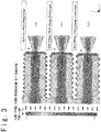
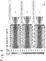
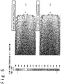
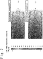
- the difference in the color (or the gray level) in FIG. 3 to FIG. 7 shows a probability that the fiber turns to an axial direction (the Y direction).
- the value is 9 ⁇ 10 -1 , it is indicated that 90% of the reinforcing fiber in the part turn to the axial direction (the Y direction).
- the gate from which the resin composition containing the reinforcing fiber at the time of injection molding is injected is arranged in the bottom B of the screw. Then, by making the resin composition flow in the axial direction at the time of the injection molding, the tensile strength of fiber reinforced resin screws 10, 20 is improved. Also, the average fiber length of the reinforcing fiber contained in fiber reinforced resin screw 10, 20 is 1 to 1/3 times of the pitch P. The orientation analysis result of the reinforcing fiber in the fiber reinforced resin screw shown in FIG. 3 and FIG. 4 will be described.
- the color boundary goes into the top shape of the thread as the angle A of thread increases. It could be understood that the flow of the reinforcing fiber contained in the resin composition is orientated more strongly along the top shape of the thread. Therefore, it is possible to determine that the strength of the thread is improved.
- the vertical axis of FIG. 8 is the tensile strength (kN).
- the symbol A of the material shows the resin composition which uses high viscosity PEEK (polyether etherketone) as the resin and which contains the glass fiber of 30% as the reinforcing fiber.
- the symbol B of the material shows the resin composition which uses low viscosity PEEK as the resin and and which contains the glass fiber of 60% as the reinforcing fiber.
- the symbol C of the material shows the resin composition which uses intermediate viscosity PEEK as the resin and which contains the glass fiber of 30% as the reinforcing fiber.
- the symbol D of the material shows the resin composition which uses low viscosity PEEK as the resin and which contains the glass fiber of 50% as the reinforcing fiber.
- the measurement results of the symbols A, B, C, and D are the tensile strength examination results about thee fiber reinforced resin screw 10, 20 which corresponds to UNF 3/16 and which has the angle A (60°) of thread and the pitch P (32 piles/the inch).
- the symbols A (1.5P), B (1.5P), C (1.5P) and D (1.5P) shows the tensile strength examination results about fiber reinforced resin screws 10, 20 which corresponds to UNF 3/16 and which has the angle A (60°) of thread, and the pitch P (21 piles/the inch).
- the average tensile strength is improved (about 4 to 10%) by setting the average fiber length of the reinforcing fiber contained in the fiber reinforced resin screw 10, 20 to 1 to 1/3 times of the pitch P and making the pitch P of the thread long.
Landscapes
- Engineering & Computer Science (AREA)
- General Engineering & Computer Science (AREA)
- Mechanical Engineering (AREA)
- Manufacturing & Machinery (AREA)
- Compositions Of Macromolecular Compounds (AREA)
- Reinforced Plastic Materials (AREA)
- Moulding By Coating Moulds (AREA)
Abstract
Description
- The present invention relates to a fiber reinforced resin screw using a resin composition containing reinforcing fiber in a resin.
- Conventionally, in the fields in which chemical resistance, corrosion resistance, biocompatibility, explosion proof property, light weight property, and heat retention are required, a resin screw using a resin as a material is sometimes used in case of carrying out a feeding operation and a fastening operation between articles
- Because the resin screw has various kinds of characteristics but is weak in strength, as compared with a metal screw, application fields are limited. Therefore, the resin screw could not be used for an application field where the higher strength is required.
- Patent Literature 1 (
JP H07-293535A Patent Literature 1, long reinforcing fiber having the average fiber length of 0.3 mm or more is mixed in a thermoplastic resin, to enhance the binding and adhesion of the reinforcing fiber and the resin, and to improve the strength of the composite material. - [Patent Literature 1]
JP H07-293535A - In the fiber reinforced resin bolt described in
Patent Literature 1, the tensile strength of the bolt is improved by strongly orientating long fiber having the average fiber length of 0.3 mm or more in parallel to an axial direction of the screw. - However, even if the tensile strength in the axial direction is improved by containing the long fiber, the strength of the threads sometimes lacks when an engagement length of the male screw and the female screw should be shortened as in case of engaging the male screw and the female screw in a narrower space.
- An object of the present invention is to improve the strength of threads in a fiber reinforced resin screw.
- A fiber reinforced resin screw of the present invention is a screw formed with a resin composition containing reinforcing fiber in a resin. The pitch of threads of the fiber reinforced resin screw has a length of 1.5 to 2 times of a standard pitch corresponding to the outer diameter of thread prescribed in the standards of a metric coarse screw, a unified coarse screw and a unified fine screw. An average fiber length of the reinforcing fiber is in a range of 1 to 1/3 times of a pitch between the threads in the fiber reinforced resin screw. The content rate of the reinforcing fiber is in a range of 20 to 80%.
- A fiber reinforced resin screw of the present invention is a screw formed of a resin composition containing reinforcing fiber in a resin. The pitch between threads in the fiber reinforced resin screw has a length of 1/4.3 to 1/2.2 times of an outer diameter of the screw. The average fiber length of the reinforcing fiber is in a range of 1 to 1/3 times of the pitch. The content rate of the reinforcing fiber is in a range of 20 to 80%.
- The angle of thread in the fiber reinforced resin screw is in a range of 60 to 90°.
- The outer diameter of the fiber reinforced resin screw is in a range of 3.5 to 10 mm.
- The resin is selected from the group consisting of aromatic polyether ketone resin, polyamide resin, polyimide resin, polyphenylene sulfide resin, polyvinylidene fluoride resin, polycarbonate resin, polyacetal resin, phenol resin, ultra-high molecular weight polyethylene resin, tetrafluoroethylene-perfluoralkyl vinyl ether resin, polybutylene terephthalate resin, and polyvinyl chloride resin.
- The reinforcing fiber is selected from the group consisting of glass fiber, carbon fiber, silicon carbide fiber, aramid fiber, and ultra-high molecular weight polyethylene fiber.
- By using the fiber reinforced resin screw according to the present invention, the resin screw with a high strength of the threads can be provided. By providing the fiber reinforced resin screw with the high strength of threads, the application fields of the resin screw can be increased to the fields requiring chemical resistance, corrosion resistance, biocompatibility, explosion proof property, light weight property, and heat retention.
-
- [
FIG. 1 ]
FIG. 1 is a partial sectional view of a fiber reinforced resin screw (a male screw) according to the present invention. - [
FIG. 2 ]
FIG. 2 is a partial sectional view of the fiber reinforced resin screw (a female screw) according to the present invention. - [
FIG. 3 ]- (a) of
FIG. 3 is a diagram showing an orientation analysis result of the reinforcing fiber in the male screw which corresponds to UNF 3/16 and which has an angle A (= 60°) of thread and the pitch P (32 threads/inch), (b) ofFIG. 3 is a diagram showing the orientation analysis result of the reinforcing fiber in the male screw which corresponds to UNF 3/16 and which has the angle A (= 75°) of thread and the pitch P changed according to the angle A, and (c) ofFIG. 3 is a diagram showing an orientation analysis result of the reinforcing fiber in the male screw which corresponds to UNF 3/16 and which has the angle A (= 90°) of thread and the pitch P changed according to the angle A.
- (a) of
- [
FIG. 4 ]- (a) of
FIG. 4 is a diagram showing the orientation analysis result of the reinforcing fiber in the male screw which corresponds to UNF 3/16 and which has the angle A (= 60°) of thread and the pitch P (32 threads/inch), (b) ofFIG. 4 is a diagram showing the orientation analysis result of the reinforcing fiber in the male screw which corresponds to UNF 3/16 and which has the angle A (= 105°) of thread and the pitch P changed according to the angle A, and (c) ofFIG. 4 is a diagram showing the orientation analysis result of the reinforcing fiber in the male screw which corresponds to UNF 3/16 and which has the angle A (= 120°) and the pitch P changed according to the angle A.
- (a) of
- [
FIG. 5 ]- (a) of
FIG. 5 is a diagram showing the orientation analysis result of the reinforcing fiber in the male screw which corresponds to UNF 3/16 and which has the angle A (= 60°) of thread and the pitch P (32 threads/inch), and (b) ofFIG. 5 is a diagram showing the orientation analysis result of the reinforcing fiber in the male screw which corresponds to UNF 3/16 and which has the pitch P changed to 1.2 times.
- (a) of
- [
FIG. 6 ]- (a) of
FIG. 6 is a diagram showing the orientation analysis result of the reinforcing fiber in the male screw which corresponds to UNF 3/16 and which has the pitch changed to 1.4 times, and (b) ofFIG. 6 is a diagram showing the orientation analysis result of the reinforcing fiber in the male screw which corresponds to UNF 3/16 and which has the pitch P changed to 1.6 times.
- (a) of
- [
FIG. 7 ]- (a) of
FIG. 7 is a diagram showing the orientation analysis result of the reinforcing fiber in the male screw which corresponds to UNF 3/16 and which has the pitch changed to 1.8 times, and (b) ofFIG. 7 is a diagram showing the orientation analysis result of the reinforcing fiber in the male screw which corresponds to UNF 3/16 and which has the pitch P changed to 2 times.
- (a) of
- [
FIG. 8 ]
FIG. 8 is a diagram showing a change of tensile strength (kN) of the fiber reinforced resin screw when the content rate of the reinforcing fiber and the resin is changed. - A fiber reinforced resin screw according to embodiments of the present invention will be described below with reference to the attached drawings.
-
FIG. 1 is a partial sectional view showing a partial section of the fiber reinforced resin screw (a male screw) according to a first embodiment.FIG. 2 is a partial sectional view showing a partial section of the fiber reinforced resin screw (a female screw) according to the first embodiment. Note that since a shape of thread of the female screw shown inFIG. 2 is similar to that of the male screw shown inFIG. 1 , the description is omitted. - Referring to
FIG. 1 and FIG. 2 , the fiber reinforcedresin screw - Here, by setting the pitch P of the fiber reinforced resin screw to be longer than the pitch of the standard screw used generally, the strength of the thread by making a root section of the thread long can be improved.
- It is desirable that the pitch P of the fiber reinforced
resin screw resin screws resin screw - When the fiber reinforced
resin screw resin screw - Also, when the pitch P of the fiber reinforced
resin screw resin screws - Also, the loosening occurs naturally when the friction angle between the threads of the fiber reinforced
resin screws resin screw - It is desirable that the average fiber length of the reinforcing fiber contained in the fiber reinforced
resin screw - The angle A of thread is 60° in the metric coarse screw, the unified coarse screw or the unified fine screw. By setting the angle A of thread in the fiber reinforced
resin screw - In the embodiment shown in
FIG. 1 and FIG. 2 , the shape of the thread of the fiber reinforcedresin screw - The raw material of the resin of the fiber reinforced
resin screw resin screw - As the reinforcing fiber, glass fiber, carbon fiber, silicon carbide fiber, aramid fiber, ultra-high molecular weight polyethylene fiber, and other reinforcing fiber can be used. The content of the reinforcing fiber in the fiber reinforced
resin screw - Next, referring to
FIG. 3 to FIG. 7 , a simulation result of the orientation of the reinforcing fiber of the fiber reinforced resin screw (the male screw) having the outer diameter D = about 4.8 mm, based on the flow of the resin at the time of the injection molding will be described. The difference in the color (or the gray level) inFIG. 3 to FIG. 7 shows a probability that the fiber turns to an axial direction (the Y direction).
When the value is 9×10⁻¹, it is indicated that 90% of the reinforcing fiber in the part turn to the axial direction (the Y direction). - The gate from which the resin composition containing the reinforcing fiber at the time of injection molding is injected is arranged in the bottom B of the screw. Then, by making the resin composition flow in the axial direction at the time of the injection molding, the tensile strength of fiber reinforced resin screws 10, 20 is improved. Also, the average fiber length of the reinforcing fiber contained in fiber reinforced
resin screw FIG. 3 andFIG. 4 will be described. - (a) of
FIG. 3 is a diagram showing an orientation analysis result of the reinforcing fiber in the male screw which corresponds to UNF 3/16 and which has the angle A (= 60°) of thread and the pitch P (32 threads/inch), (b) ofFIG. 3 is a diagram showing the orientation analysis result of the reinforcing fiber in the male screw which corresponds to UNF 3/16 and which has the angle A (= 75°) of thread and the pitch P changed according to the angle A, and (c) ofFIG. 3 is a diagram showing an orientation analysis result of the reinforcing fiber in the male screw which corresponds to UNF 3/16 and which has the angle A (= 90°) of thread and the pitch P changed according to the angle A. - (a) of
FIG. 4 is a diagram showing an orientation analysis result of the reinforcing fiber in the male screw which corresponds to UNF 3/16 and which has the angle A (= 60°) of thread and the pitch P (32 threads/inch), (b) ofFIG. 4 is a diagram showing an orientation analysis result of the reinforcing fiber in the male screw which corresponds to UNF 3/16 and which has the angle A (= 105°) and the pitch P changed according to the angle A, and (c) ofFIG. 4 is a diagram showing an orientation analysis result of the reinforcing fiber in the male screw which corresponds to UNF 3/16 and which has the angle A (= 120°) and the pitch P changed according to the angle A. - As shown in
FIG. 3 andFIG. 4 , the color boundary goes into the top shape of the thread as the angle A of thread increases. It could be understood that the flow of the reinforcing fiber contained in the resin composition is orientated more strongly along the top shape of the thread. Therefore, it is possible to determine that the strength of the thread is improved. Note that the simulation results shown inFIG. 3 andFIG. 4 are the orientation analysis results of the reinforcing fiber about the fiber reinforced resin screw having the outer diameter D = about 4.8 mm. However, this is met in the same way about the fiber reinforced resin screw having the outer diameter D in the range of 3.5 mm ≤ D ≤ 10 mm. - Next, the orientation analysis results of the reinforcing fiber in the fiber reinforced resin screws shown in
FIG. 5 to FIG. 7 will be described. -
- (a) of
FIG. 5 is a diagram showing an orientation analysis result of the reinforcing fiber in the male screw which corresponds to UNF 3/16 and which has the angle A (= 60°) of thread and the pitch P (32 threads/inch), and (b) ofFIG. 5 is a diagram showing the orientation analysis result of the reinforcing fiber in the male screw which corresponds to UNF 3/16 and in which the pitch P is changed to 1.2 times. -
- (a) of
FIG. 6 is a diagram showing an orientation analysis result of the reinforcing fiber in the male screw which corresponds to UNF 3/16 and in which the pitch is changed to 1.4 times, and (b) ofFIG. 6 is a diagram showing an orientation analysis result of the reinforcing fiber in the male screw which corresponds to UNF 3/16 and in which the pitch P is changed to 1.6 times. -
- (a) of
FIG. 7 is a diagram showing an orientation analysis result of the reinforcing fiber in the male screw which corresponds to UNF 3/16 and in which the pitch is changed to 1.8 times, and (b) ofFIG. 7 is a diagram showing an orientation analysis result of the reinforcing fiber in the male screw which corresponds to UNF 3/16 and in which the pitch P is changed to twice. - As shown in
FIG. 5 to FIG. 7 , the root section of the thread becomes long as the pitch P of the thread increases. Also, it could be understood that the flow of the reinforcing fiber contained in the resin composition is orientated more strongly along the top shape of the thread. Therefore, it is possible to determine that the strength of the thread is improved. Note that the simulation results shown inFIG. 5 to FIG. 7 are the orientation analysis results of the reinforcing fiber about the fiber reinforced resin screws having the outer diameter D = about 4.8 mm, but this is met about the fiber reinforced resin screw having the outer diameter D in the range of 3.5 mm ≤ D ≤10 mm. - The examination result of tensile strength in the condition that the fiber reinforced resin screws 10 and 20 shown in
FIG. 1 and FIG. 2 are engaged will be described with reference toFIG. 8. FIG. 8 is a diagram showing the change of the tensile strength when the content rate of the resin and the reinforcing fiber is changed about the fiber reinforcedresin screw 10 having the outer diameter D D = about 4.8 mm. The vertical axis ofFIG. 8 is the tensile strength (kN). - The symbol A of the material shows the resin composition which uses high viscosity PEEK (polyether etherketone) as the resin and which contains the glass fiber of 30% as the reinforcing fiber. The symbol B of the material shows the resin composition which uses low viscosity PEEK as the resin and and which contains the glass fiber of 60% as the reinforcing fiber. The symbol C of the material shows the resin composition which uses intermediate viscosity PEEK as the resin and which contains the glass fiber of 30% as the reinforcing fiber. The symbol D of the material shows the resin composition which uses low viscosity PEEK as the resin and which contains the glass fiber of 50% as the reinforcing fiber.
- The measurement results of the symbols A, B, C, and D are the tensile strength examination results about thee fiber reinforced
resin screw - As shown in
FIG. 8 , it could be seen that the average tensile strength is improved (about 4 to 10%) by setting the average fiber length of the reinforcing fiber contained in the fiber reinforcedresin screw - In the above, the fiber reinforced resin screws of various embodiments have been described but the present invention is not limited to the above embodiments. Various modifications can be carried out to the above embodiments. In the range in which technical contradiction does not occur, the technical matter in one embodiment can be combined with the technical matter in another embodiment.
Claims (10)
- A fiber reinforced resin screw formed with a resin composition containing reinforcing fiber in a resin,
wherein a pitch of threads of the fiber reinforced resin screw has a length of 1.5 to 2 times of a standard pitch corresponding to an outer diameter of the threads prescribed in standards of a metric coarse screw, a unified coarse screw and a unified fine screw,
wherein an average fiber length of the reinforcing fiber is 1 to 1/3 times of the pitch of the threads in the fiber reinforced resin screw, and
wherein a content rate of the reinforcing fiber is in a range of 20 to 80%. - The fiber reinforced resin screw according to claim 1, wherein an angle of thread in the fiber reinforced resin screw is in a range of 60 to 90°.
- The fiber reinforced resin screw according to claim 1 or 2, wherein the outer diameter of the fiber reinforced resin screw is in a range of 3.5 to 10 mm.
- The fiber reinforced resin screw according to any one of claims 1 to 3, wherein the resin is selected from the group consisting of aromatic polyether ketone resin, polyamide resin, polyimide resin, polyphenylene sulfide resin, polyvinylidene fluoride resin, polycarbonate resin, polyacetal resin, phenol resin, ultra-high molecular weight polyethylene resin, tetrafluoroethylene-perfluoralkyl vinyl ether resin, polybutylene terephthalate resin, and polyvinyl chloride resin.
- The fiber reinforced resin screw according to any one of claims 1 to 4, wherein the reinforcing fiber is selected from the group consisting of glass fiber, carbon fiber, silicon carbide fiber, aramid fiber, and ultra-high molecular weight polyethylene fiber.
- A fiber reinforced resin screw formed with a resin composition containing reinforcing fiber in a resin,
wherein a pitch of threads in the fiber reinforced resin screw has a length of 1/4.3 to 1/2.2 times of an outer diameter of the screw,
wherein an average fiber length of the reinforcing fiber is 1 to 1/3 times of the pitch, and
wherein a content rate of the reinforcing fiber is in a range of 20 to 80%. - The fiber reinforced resin screw according to claim 6, wherein an angle of the thread in the fiber reinforced resin screw is in a range of 60 to 90°.
- The fiber reinforced resin screw according to claim 6 or 7, wherein an outer diameter of the fiber reinforced resin screw is in a range of 3.5 to 10 mm.
- The fiber reinforced resin screw according to any one of claims 6 to 8, wherein the resin is selected from the group consisting of aromatic polyether ketone resin, polyamide resin, polyimide resin, polyphenylene sulfide resin, polyvinylidene fluoride resin, polycarbonate resin, polyacetal resin, phenol resin, ultra-high molecular weight polyethylene resin, tetrafluoroethylene-perfluoralkyl vinyl ether resin, polybutylene terephthalate resin, and polyvinyl chloride resin.
- The fiber reinforced resin screw according to any one of claims 6 to 9, wherein the reinforcing fiber is selected from the group consisting of glass fiber, carbon fiber, silicon carbide fiber, aramid fiber, and ultra-high molecular weight polyethylene fiber.
Applications Claiming Priority (2)
| Application Number | Priority Date | Filing Date | Title |
|---|---|---|---|
| JP2014236516A JP6584066B2 (en) | 2014-11-21 | 2014-11-21 | Fiber reinforced plastic screw |
| PCT/JP2015/083300 WO2016080554A1 (en) | 2014-11-21 | 2015-11-19 | Fiber-reinforced resin screw |
Publications (3)
| Publication Number | Publication Date |
|---|---|
| EP3199825A1 true EP3199825A1 (en) | 2017-08-02 |
| EP3199825A4 EP3199825A4 (en) | 2017-11-29 |
| EP3199825B1 EP3199825B1 (en) | 2019-01-02 |
Family
ID=56014081
Family Applications (1)
| Application Number | Title | Priority Date | Filing Date |
|---|---|---|---|
| EP15862015.3A Active EP3199825B1 (en) | 2014-11-21 | 2015-11-19 | Fiber-reinforced resin screw |
Country Status (7)
| Country | Link |
|---|---|
| US (1) | US10533596B2 (en) |
| EP (1) | EP3199825B1 (en) |
| JP (1) | JP6584066B2 (en) |
| CN (1) | CN107208683B (en) |
| BR (1) | BR112017007250A2 (en) |
| CA (1) | CA2965606C (en) |
| WO (1) | WO2016080554A1 (en) |
Cited By (1)
| Publication number | Priority date | Publication date | Assignee | Title |
|---|---|---|---|---|
| EP3511582A1 (en) * | 2018-01-12 | 2019-07-17 | CTG Carbon Team Germany GmbH | Carbon fibre screw |
Families Citing this family (12)
| Publication number | Priority date | Publication date | Assignee | Title |
|---|---|---|---|---|
| JP6777910B2 (en) * | 2016-07-15 | 2020-10-28 | 日本ケミカルスクリュー株式会社 | Bolt molding method and bolts, and bolt molding molds |
| EP3427921B1 (en) | 2017-07-14 | 2021-11-17 | Crompton Technology Group Limited | Composite ball screw |
| JP7049887B2 (en) * | 2018-03-29 | 2022-04-07 | 三菱重工機械システム株式会社 | Liquid filling valve and filling machine |
| CN108729565A (en) * | 2018-07-02 | 2018-11-02 | 沈阳建筑大学 | A kind of disconnected heat bridge threaded connector and disconnected heat bridge method |
| JP7362109B2 (en) * | 2019-06-17 | 2023-10-17 | 株式会社呉英製作所 | Water stop bolt member, decorative cap member for scaffold connecting anchor, and method for assembling decorative cap member for scaffold connecting anchor |
| CN110259796A (en) * | 2019-07-11 | 2019-09-20 | 海盐精工标准件厂 | A kind of bolt |
| EP3800035A1 (en) | 2019-10-04 | 2021-04-07 | Crompton Technology Group Limited | Composite component with means to visually detect barely visible impact damage |
| EP3800036A1 (en) * | 2019-10-04 | 2021-04-07 | Crompton Technology Group Limited | Composite component with means to visually detect barely visible impact damage |
| JP7555226B2 (en) * | 2019-10-07 | 2024-09-24 | Ntn株式会社 | Plastic Nut |
| KR102232209B1 (en) * | 2019-12-13 | 2021-03-24 | 이성권 | Corrosion-resistant bolt and nut applied to equipment for waste fluid treatment in industrial facilities |
| JP7007543B2 (en) * | 2020-08-31 | 2022-01-24 | 株式会社NejiLaw | Male body |
| DE102024116060B3 (en) * | 2024-06-10 | 2025-06-05 | Bayerische Motoren Werke Aktiengesellschaft | Fastening arrangement of a lighting device to a component of a vehicle and vehicle |
Family Cites Families (20)
| Publication number | Priority date | Publication date | Assignee | Title |
|---|---|---|---|---|
| US2949054A (en) * | 1954-07-19 | 1960-08-16 | Glastic Corp | Threaded shaft of glass fiber reinforced plastic |
| AU5768573A (en) * | 1973-07-04 | 1975-01-09 | Screw-threaded members | |
| JPS60201932A (en) * | 1984-03-26 | 1985-10-12 | Sekisui Chem Co Ltd | Fiber reinforced plastic screw-shaped molding and manufacture thereof |
| US4909690A (en) * | 1987-12-16 | 1990-03-20 | Textron Inc. | Composite fastener |
| JPH01310941A (en) * | 1988-06-09 | 1989-12-15 | Osaka Gas Co Ltd | Reinforced plastic rod, method and apparatus for preparing the same, reinforced plastic screw, and method and apparatus for preparing the same |
| US5057257A (en) * | 1990-02-20 | 1991-10-15 | Quantum Composites, Inc. | Method of transfer molding fiber-reinforced resin bolt products |
| US5234765A (en) * | 1991-02-08 | 1993-08-10 | Taylor Scott R | High torque and tensile strength threaded end for thermoplastic composite rod |
| DE4209265A1 (en) * | 1991-12-21 | 1993-06-24 | Dyckerhoff & Widmann Ag | DEVICE FOR ANCHORING A ROD-SHAPED TENSION LINK MADE OF FIBER COMPOSITE MATERIAL |
| JPH07293535A (en) | 1994-04-21 | 1995-11-07 | Polyplastics Co | Resin bolt and its molding method |
| JPH07293534A (en) * | 1994-04-21 | 1995-11-07 | Polyplastics Co | Resin bolt and its molding method |
| DE4415195C2 (en) | 1994-04-30 | 1996-09-19 | Hoechst Ag | Long fiber reinforced screws and threaded rods made of thermoplastic materials, these screws and threaded rods and processes for their production |
| JP3381535B2 (en) * | 1996-11-07 | 2003-03-04 | チッソ株式会社 | Long / short fiber reinforced polyolefin composite structure and molded article comprising the same |
| JP3901299B2 (en) * | 1997-10-02 | 2007-04-04 | 双和化成株式会社 | U bolt manufacturing method |
| JP2003056536A (en) * | 2001-08-08 | 2003-02-26 | Sanko Techno Co Ltd | Fiber-reinforced synthetic resin bolt and nut |
| DE102004021484B4 (en) * | 2004-04-30 | 2018-11-29 | Böllhoff Verbindungstechnik GmbH | Method for producing a connection arrangement |
| US8465241B2 (en) * | 2007-10-31 | 2013-06-18 | The Boeing Company | Composite fasteners containing multiple reinforcing fiber types |
| KR20100130286A (en) * | 2009-06-03 | 2010-12-13 | 에스케이케미칼주식회사 | Fiber Reinforced Resin Bolt and Manufacturing Method |
| US8758387B2 (en) * | 2011-07-15 | 2014-06-24 | University Of Iowa Research Foundation | Biofeedback training of anal and rectal muscles |
| JP2015510459A (en) * | 2012-01-17 | 2015-04-09 | グリーン, ツイード テクノロジーズ, インコーポレイテッド | Molded composite screw |
| JP2014111980A (en) * | 2012-11-12 | 2014-06-19 | Kitagawa Kogyo Co Ltd | Screw |
-
2014
- 2014-11-21 JP JP2014236516A patent/JP6584066B2/en active Active
-
2015
- 2015-11-19 CN CN201580056548.0A patent/CN107208683B/en not_active Expired - Fee Related
- 2015-11-19 EP EP15862015.3A patent/EP3199825B1/en active Active
- 2015-11-19 CA CA2965606A patent/CA2965606C/en active Active
- 2015-11-19 BR BR112017007250-5A patent/BR112017007250A2/en not_active IP Right Cessation
- 2015-11-19 US US15/519,706 patent/US10533596B2/en active Active
- 2015-11-19 WO PCT/JP2015/083300 patent/WO2016080554A1/en not_active Ceased
Cited By (1)
| Publication number | Priority date | Publication date | Assignee | Title |
|---|---|---|---|---|
| EP3511582A1 (en) * | 2018-01-12 | 2019-07-17 | CTG Carbon Team Germany GmbH | Carbon fibre screw |
Also Published As
| Publication number | Publication date |
|---|---|
| CA2965606C (en) | 2018-10-23 |
| CN107208683B (en) | 2020-04-07 |
| CN107208683A (en) | 2017-09-26 |
| JP2016098910A (en) | 2016-05-30 |
| WO2016080554A1 (en) | 2016-05-26 |
| EP3199825B1 (en) | 2019-01-02 |
| US10533596B2 (en) | 2020-01-14 |
| BR112017007250A2 (en) | 2018-01-16 |
| EP3199825A4 (en) | 2017-11-29 |
| JP6584066B2 (en) | 2019-10-02 |
| US20170241465A1 (en) | 2017-08-24 |
| CA2965606A1 (en) | 2016-05-26 |
Similar Documents
| Publication | Publication Date | Title |
|---|---|---|
| EP3199825B1 (en) | Fiber-reinforced resin screw | |
| DE102008042722B4 (en) | sensor housing | |
| DE202012010853U1 (en) | bottle | |
| Alonso et al. | Quantifying aromaticity according to the energetic criterion | |
| DE102012215668B4 (en) | Sliding surface, especially for a bearing | |
| WO2013041491A1 (en) | Pipe connecting device and method for production thereof | |
| DE102019114008A1 (en) | Tolerance compensation fastening system with improved functionality | |
| TW201905052A (en) | Fiber reinforced plastic | |
| US11236776B2 (en) | Retainer | |
| CN105295266A (en) | Formula of corrosion-resistant plastic composite material | |
| DE102014212072A1 (en) | Bearing cage or bearing cage segment | |
| DE202008009019U1 (en) | Door gauge for positioning door leaf and frame fishing | |
| KR20220041086A (en) | Infeed prepregs and fiber-reinforced plastics | |
| EP0501519A1 (en) | Self tapping screw | |
| CN106292835B (en) | Knob structure | |
| DE202006015585U1 (en) | Two-component rope pulley | |
| US9982702B2 (en) | Threaded sleeve | |
| CN104437296A (en) | Sealing element for high borosilicate glass reaction kettle | |
| CN108707316A (en) | A kind of novel glass Steel material | |
| CN106633788A (en) | Engineering plastic material and preparation method | |
| CN106497014A (en) | A kind of engineering plastic materials and preparation method | |
| CN204000938U (en) | A kind of drainage inspection well seat | |
| DE102018117464A1 (en) | Connection system, cover part and manufacturing method | |
| DE102007040097A1 (en) | gasket | |
| DE102019115741A1 (en) | Stiffened fan housing part for arrangement on a gas fan |
Legal Events
| Date | Code | Title | Description |
|---|---|---|---|
| STAA | Information on the status of an ep patent application or granted ep patent |
Free format text: STATUS: THE INTERNATIONAL PUBLICATION HAS BEEN MADE |
|
| PUAI | Public reference made under article 153(3) epc to a published international application that has entered the european phase |
Free format text: ORIGINAL CODE: 0009012 |
|
| STAA | Information on the status of an ep patent application or granted ep patent |
Free format text: STATUS: REQUEST FOR EXAMINATION WAS MADE |
|
| 17P | Request for examination filed |
Effective date: 20170424 |
|
| AK | Designated contracting states |
Kind code of ref document: A1 Designated state(s): AL AT BE BG CH CY CZ DE DK EE ES FI FR GB GR HR HU IE IS IT LI LT LU LV MC MK MT NL NO PL PT RO RS SE SI SK SM TR |
|
| AX | Request for extension of the european patent |
Extension state: BA ME |
|
| A4 | Supplementary search report drawn up and despatched |
Effective date: 20171026 |
|
| RIC1 | Information provided on ipc code assigned before grant |
Ipc: B29D 1/00 20060101ALI20171020BHEP Ipc: B29C 45/00 20060101AFI20171020BHEP Ipc: B29K 309/08 20060101ALN20171020BHEP Ipc: B29K 71/00 20060101ALN20171020BHEP Ipc: B29L 1/00 20060101ALN20171020BHEP Ipc: F16B 33/02 20060101ALI20171020BHEP Ipc: F16B 33/00 20060101ALI20171020BHEP Ipc: F16B 37/00 20060101ALI20171020BHEP Ipc: B29K 105/14 20060101ALN20171020BHEP Ipc: F16B 35/00 20060101ALI20171020BHEP |
|
| DAV | Request for validation of the european patent (deleted) | ||
| DAX | Request for extension of the european patent (deleted) | ||
| REG | Reference to a national code |
Ref country code: DE Ref legal event code: R079 Ref document number: 602015023014 Country of ref document: DE Free format text: PREVIOUS MAIN CLASS: F16B0035000000 Ipc: B29C0045000000 |
|
| GRAP | Despatch of communication of intention to grant a patent |
Free format text: ORIGINAL CODE: EPIDOSNIGR1 |
|
| STAA | Information on the status of an ep patent application or granted ep patent |
Free format text: STATUS: GRANT OF PATENT IS INTENDED |
|
| RIC1 | Information provided on ipc code assigned before grant |
Ipc: B29C 45/00 20060101AFI20180705BHEP Ipc: B29L 1/00 20060101ALN20180705BHEP Ipc: B29K 71/00 20060101ALN20180705BHEP Ipc: B29K 309/08 20060101ALN20180705BHEP Ipc: F16B 37/00 20060101ALI20180705BHEP Ipc: B29K 105/14 20060101ALN20180705BHEP Ipc: F16B 33/02 20060101ALI20180705BHEP Ipc: F16B 35/00 20060101ALI20180705BHEP Ipc: F16B 33/00 20060101ALI20180705BHEP Ipc: B29D 1/00 20060101ALI20180705BHEP |
|
| INTG | Intention to grant announced |
Effective date: 20180720 |
|
| GRAS | Grant fee paid |
Free format text: ORIGINAL CODE: EPIDOSNIGR3 |
|
| GRAA | (expected) grant |
Free format text: ORIGINAL CODE: 0009210 |
|
| STAA | Information on the status of an ep patent application or granted ep patent |
Free format text: STATUS: THE PATENT HAS BEEN GRANTED |
|
| AK | Designated contracting states |
Kind code of ref document: B1 Designated state(s): AL AT BE BG CH CY CZ DE DK EE ES FI FR GB GR HR HU IE IS IT LI LT LU LV MC MK MT NL NO PL PT RO RS SE SI SK SM TR |
|
| REG | Reference to a national code |
Ref country code: GB Ref legal event code: FG4D |
|
| REG | Reference to a national code |
Ref country code: CH Ref legal event code: EP Ref country code: AT Ref legal event code: REF Ref document number: 1083785 Country of ref document: AT Kind code of ref document: T Effective date: 20190115 |
|
| REG | Reference to a national code |
Ref country code: IE Ref legal event code: FG4D |
|
| REG | Reference to a national code |
Ref country code: DE Ref legal event code: R096 Ref document number: 602015023014 Country of ref document: DE |
|
| REG | Reference to a national code |
Ref country code: NL Ref legal event code: MP Effective date: 20190102 |
|
| REG | Reference to a national code |
Ref country code: LT Ref legal event code: MG4D |
|
| REG | Reference to a national code |
Ref country code: AT Ref legal event code: MK05 Ref document number: 1083785 Country of ref document: AT Kind code of ref document: T Effective date: 20190102 |
|
| PG25 | Lapsed in a contracting state [announced via postgrant information from national office to epo] |
Ref country code: NL Free format text: LAPSE BECAUSE OF FAILURE TO SUBMIT A TRANSLATION OF THE DESCRIPTION OR TO PAY THE FEE WITHIN THE PRESCRIBED TIME-LIMIT Effective date: 20190102 |
|
| PG25 | Lapsed in a contracting state [announced via postgrant information from national office to epo] |
Ref country code: LT Free format text: LAPSE BECAUSE OF FAILURE TO SUBMIT A TRANSLATION OF THE DESCRIPTION OR TO PAY THE FEE WITHIN THE PRESCRIBED TIME-LIMIT Effective date: 20190102 Ref country code: SE Free format text: LAPSE BECAUSE OF FAILURE TO SUBMIT A TRANSLATION OF THE DESCRIPTION OR TO PAY THE FEE WITHIN THE PRESCRIBED TIME-LIMIT Effective date: 20190102 Ref country code: FI Free format text: LAPSE BECAUSE OF FAILURE TO SUBMIT A TRANSLATION OF THE DESCRIPTION OR TO PAY THE FEE WITHIN THE PRESCRIBED TIME-LIMIT Effective date: 20190102 Ref country code: ES Free format text: LAPSE BECAUSE OF FAILURE TO SUBMIT A TRANSLATION OF THE DESCRIPTION OR TO PAY THE FEE WITHIN THE PRESCRIBED TIME-LIMIT Effective date: 20190102 Ref country code: NO Free format text: LAPSE BECAUSE OF FAILURE TO SUBMIT A TRANSLATION OF THE DESCRIPTION OR TO PAY THE FEE WITHIN THE PRESCRIBED TIME-LIMIT Effective date: 20190402 Ref country code: PT Free format text: LAPSE BECAUSE OF FAILURE TO SUBMIT A TRANSLATION OF THE DESCRIPTION OR TO PAY THE FEE WITHIN THE PRESCRIBED TIME-LIMIT Effective date: 20190502 Ref country code: PL Free format text: LAPSE BECAUSE OF FAILURE TO SUBMIT A TRANSLATION OF THE DESCRIPTION OR TO PAY THE FEE WITHIN THE PRESCRIBED TIME-LIMIT Effective date: 20190102 |
|
| PG25 | Lapsed in a contracting state [announced via postgrant information from national office to epo] |
Ref country code: IS Free format text: LAPSE BECAUSE OF FAILURE TO SUBMIT A TRANSLATION OF THE DESCRIPTION OR TO PAY THE FEE WITHIN THE PRESCRIBED TIME-LIMIT Effective date: 20190502 Ref country code: LV Free format text: LAPSE BECAUSE OF FAILURE TO SUBMIT A TRANSLATION OF THE DESCRIPTION OR TO PAY THE FEE WITHIN THE PRESCRIBED TIME-LIMIT Effective date: 20190102 Ref country code: GR Free format text: LAPSE BECAUSE OF FAILURE TO SUBMIT A TRANSLATION OF THE DESCRIPTION OR TO PAY THE FEE WITHIN THE PRESCRIBED TIME-LIMIT Effective date: 20190403 Ref country code: HR Free format text: LAPSE BECAUSE OF FAILURE TO SUBMIT A TRANSLATION OF THE DESCRIPTION OR TO PAY THE FEE WITHIN THE PRESCRIBED TIME-LIMIT Effective date: 20190102 Ref country code: RS Free format text: LAPSE BECAUSE OF FAILURE TO SUBMIT A TRANSLATION OF THE DESCRIPTION OR TO PAY THE FEE WITHIN THE PRESCRIBED TIME-LIMIT Effective date: 20190102 Ref country code: BG Free format text: LAPSE BECAUSE OF FAILURE TO SUBMIT A TRANSLATION OF THE DESCRIPTION OR TO PAY THE FEE WITHIN THE PRESCRIBED TIME-LIMIT Effective date: 20190402 |
|
| REG | Reference to a national code |
Ref country code: DE Ref legal event code: R097 Ref document number: 602015023014 Country of ref document: DE |
|
| PG25 | Lapsed in a contracting state [announced via postgrant information from national office to epo] |
Ref country code: AL Free format text: LAPSE BECAUSE OF FAILURE TO SUBMIT A TRANSLATION OF THE DESCRIPTION OR TO PAY THE FEE WITHIN THE PRESCRIBED TIME-LIMIT Effective date: 20190102 Ref country code: AT Free format text: LAPSE BECAUSE OF FAILURE TO SUBMIT A TRANSLATION OF THE DESCRIPTION OR TO PAY THE FEE WITHIN THE PRESCRIBED TIME-LIMIT Effective date: 20190102 Ref country code: RO Free format text: LAPSE BECAUSE OF FAILURE TO SUBMIT A TRANSLATION OF THE DESCRIPTION OR TO PAY THE FEE WITHIN THE PRESCRIBED TIME-LIMIT Effective date: 20190102 Ref country code: CZ Free format text: LAPSE BECAUSE OF FAILURE TO SUBMIT A TRANSLATION OF THE DESCRIPTION OR TO PAY THE FEE WITHIN THE PRESCRIBED TIME-LIMIT Effective date: 20190102 Ref country code: EE Free format text: LAPSE BECAUSE OF FAILURE TO SUBMIT A TRANSLATION OF THE DESCRIPTION OR TO PAY THE FEE WITHIN THE PRESCRIBED TIME-LIMIT Effective date: 20190102 Ref country code: IT Free format text: LAPSE BECAUSE OF FAILURE TO SUBMIT A TRANSLATION OF THE DESCRIPTION OR TO PAY THE FEE WITHIN THE PRESCRIBED TIME-LIMIT Effective date: 20190102 Ref country code: DK Free format text: LAPSE BECAUSE OF FAILURE TO SUBMIT A TRANSLATION OF THE DESCRIPTION OR TO PAY THE FEE WITHIN THE PRESCRIBED TIME-LIMIT Effective date: 20190102 Ref country code: SK Free format text: LAPSE BECAUSE OF FAILURE TO SUBMIT A TRANSLATION OF THE DESCRIPTION OR TO PAY THE FEE WITHIN THE PRESCRIBED TIME-LIMIT Effective date: 20190102 |
|
| PLBE | No opposition filed within time limit |
Free format text: ORIGINAL CODE: 0009261 |
|
| STAA | Information on the status of an ep patent application or granted ep patent |
Free format text: STATUS: NO OPPOSITION FILED WITHIN TIME LIMIT |
|
| PG25 | Lapsed in a contracting state [announced via postgrant information from national office to epo] |
Ref country code: SM Free format text: LAPSE BECAUSE OF FAILURE TO SUBMIT A TRANSLATION OF THE DESCRIPTION OR TO PAY THE FEE WITHIN THE PRESCRIBED TIME-LIMIT Effective date: 20190102 |
|
| 26N | No opposition filed |
Effective date: 20191003 |
|
| PG25 | Lapsed in a contracting state [announced via postgrant information from national office to epo] |
Ref country code: SI Free format text: LAPSE BECAUSE OF FAILURE TO SUBMIT A TRANSLATION OF THE DESCRIPTION OR TO PAY THE FEE WITHIN THE PRESCRIBED TIME-LIMIT Effective date: 20190102 |
|
| PG25 | Lapsed in a contracting state [announced via postgrant information from national office to epo] |
Ref country code: TR Free format text: LAPSE BECAUSE OF FAILURE TO SUBMIT A TRANSLATION OF THE DESCRIPTION OR TO PAY THE FEE WITHIN THE PRESCRIBED TIME-LIMIT Effective date: 20190102 |
|
| REG | Reference to a national code |
Ref country code: CH Ref legal event code: PL |
|
| PG25 | Lapsed in a contracting state [announced via postgrant information from national office to epo] |
Ref country code: LI Free format text: LAPSE BECAUSE OF NON-PAYMENT OF DUE FEES Effective date: 20191130 Ref country code: MC Free format text: LAPSE BECAUSE OF FAILURE TO SUBMIT A TRANSLATION OF THE DESCRIPTION OR TO PAY THE FEE WITHIN THE PRESCRIBED TIME-LIMIT Effective date: 20190102 Ref country code: CH Free format text: LAPSE BECAUSE OF NON-PAYMENT OF DUE FEES Effective date: 20191130 Ref country code: LU Free format text: LAPSE BECAUSE OF NON-PAYMENT OF DUE FEES Effective date: 20191119 |
|
| REG | Reference to a national code |
Ref country code: BE Ref legal event code: MM Effective date: 20191130 |
|
| PG25 | Lapsed in a contracting state [announced via postgrant information from national office to epo] |
Ref country code: IE Free format text: LAPSE BECAUSE OF NON-PAYMENT OF DUE FEES Effective date: 20191119 |
|
| PG25 | Lapsed in a contracting state [announced via postgrant information from national office to epo] |
Ref country code: BE Free format text: LAPSE BECAUSE OF NON-PAYMENT OF DUE FEES Effective date: 20191130 |
|
| PG25 | Lapsed in a contracting state [announced via postgrant information from national office to epo] |
Ref country code: CY Free format text: LAPSE BECAUSE OF FAILURE TO SUBMIT A TRANSLATION OF THE DESCRIPTION OR TO PAY THE FEE WITHIN THE PRESCRIBED TIME-LIMIT Effective date: 20190102 |
|
| PG25 | Lapsed in a contracting state [announced via postgrant information from national office to epo] |
Ref country code: HU Free format text: LAPSE BECAUSE OF FAILURE TO SUBMIT A TRANSLATION OF THE DESCRIPTION OR TO PAY THE FEE WITHIN THE PRESCRIBED TIME-LIMIT; INVALID AB INITIO Effective date: 20151119 Ref country code: MT Free format text: LAPSE BECAUSE OF FAILURE TO SUBMIT A TRANSLATION OF THE DESCRIPTION OR TO PAY THE FEE WITHIN THE PRESCRIBED TIME-LIMIT Effective date: 20190102 |
|
| PG25 | Lapsed in a contracting state [announced via postgrant information from national office to epo] |
Ref country code: MK Free format text: LAPSE BECAUSE OF FAILURE TO SUBMIT A TRANSLATION OF THE DESCRIPTION OR TO PAY THE FEE WITHIN THE PRESCRIBED TIME-LIMIT Effective date: 20190102 |
|
| PGFP | Annual fee paid to national office [announced via postgrant information from national office to epo] |
Ref country code: GB Payment date: 20220930 Year of fee payment: 8 |
|
| GBPC | Gb: european patent ceased through non-payment of renewal fee |
Effective date: 20231119 |
|
| PG25 | Lapsed in a contracting state [announced via postgrant information from national office to epo] |
Ref country code: GB Free format text: LAPSE BECAUSE OF NON-PAYMENT OF DUE FEES Effective date: 20231119 |
|
| PG25 | Lapsed in a contracting state [announced via postgrant information from national office to epo] |
Ref country code: GB Free format text: LAPSE BECAUSE OF NON-PAYMENT OF DUE FEES Effective date: 20231119 |
|
| PGFP | Annual fee paid to national office [announced via postgrant information from national office to epo] |
Ref country code: FR Payment date: 20250930 Year of fee payment: 11 |
|
| PGFP | Annual fee paid to national office [announced via postgrant information from national office to epo] |
Ref country code: DE Payment date: 20250930 Year of fee payment: 11 |