EP3199615A1 - Nucleic acid analysis device - Google Patents
Nucleic acid analysis device Download PDFInfo
- Publication number
- EP3199615A1 EP3199615A1 EP15845209.4A EP15845209A EP3199615A1 EP 3199615 A1 EP3199615 A1 EP 3199615A1 EP 15845209 A EP15845209 A EP 15845209A EP 3199615 A1 EP3199615 A1 EP 3199615A1
- Authority
- EP
- European Patent Office
- Prior art keywords
- nucleic acid
- flow passage
- electrode
- unit
- inspection
- Prior art date
- Legal status (The legal status is an assumption and is not a legal conclusion. Google has not performed a legal analysis and makes no representation as to the accuracy of the status listed.)
- Withdrawn
Links
Images
















Classifications
-
- B—PERFORMING OPERATIONS; TRANSPORTING
- B01—PHYSICAL OR CHEMICAL PROCESSES OR APPARATUS IN GENERAL
- B01L—CHEMICAL OR PHYSICAL LABORATORY APPARATUS FOR GENERAL USE
- B01L7/00—Heating or cooling apparatus; Heat insulating devices
- B01L7/52—Heating or cooling apparatus; Heat insulating devices with provision for submitting samples to a predetermined sequence of different temperatures, e.g. for treating nucleic acid samples
-
- G—PHYSICS
- G01—MEASURING; TESTING
- G01N—INVESTIGATING OR ANALYSING MATERIALS BY DETERMINING THEIR CHEMICAL OR PHYSICAL PROPERTIES
- G01N27/00—Investigating or analysing materials by the use of electric, electrochemical, or magnetic means
- G01N27/26—Investigating or analysing materials by the use of electric, electrochemical, or magnetic means by investigating electrochemical variables; by using electrolysis or electrophoresis
- G01N27/28—Electrolytic cell components
- G01N27/30—Electrodes, e.g. test electrodes; Half-cells
- G01N27/327—Biochemical electrodes, e.g. electrical or mechanical details for in vitro measurements
- G01N27/3275—Sensing specific biomolecules, e.g. nucleic acid strands, based on an electrode surface reaction
- G01N27/3276—Sensing specific biomolecules, e.g. nucleic acid strands, based on an electrode surface reaction being a hybridisation with immobilised receptors
-
- B—PERFORMING OPERATIONS; TRANSPORTING
- B01—PHYSICAL OR CHEMICAL PROCESSES OR APPARATUS IN GENERAL
- B01L—CHEMICAL OR PHYSICAL LABORATORY APPARATUS FOR GENERAL USE
- B01L3/00—Containers or dishes for laboratory use, e.g. laboratory glassware; Droppers
- B01L3/50—Containers for the purpose of retaining a material to be analysed, e.g. test tubes
- B01L3/502—Containers for the purpose of retaining a material to be analysed, e.g. test tubes with fluid transport, e.g. in multi-compartment structures
- B01L3/5027—Containers for the purpose of retaining a material to be analysed, e.g. test tubes with fluid transport, e.g. in multi-compartment structures by integrated microfluidic structures, i.e. dimensions of channels and chambers are such that surface tension forces are important, e.g. lab-on-a-chip
- B01L3/502707—Containers for the purpose of retaining a material to be analysed, e.g. test tubes with fluid transport, e.g. in multi-compartment structures by integrated microfluidic structures, i.e. dimensions of channels and chambers are such that surface tension forces are important, e.g. lab-on-a-chip characterised by the manufacture of the container or its components
-
- G—PHYSICS
- G01—MEASURING; TESTING
- G01N—INVESTIGATING OR ANALYSING MATERIALS BY DETERMINING THEIR CHEMICAL OR PHYSICAL PROPERTIES
- G01N27/00—Investigating or analysing materials by the use of electric, electrochemical, or magnetic means
- G01N27/26—Investigating or analysing materials by the use of electric, electrochemical, or magnetic means by investigating electrochemical variables; by using electrolysis or electrophoresis
- G01N27/28—Electrolytic cell components
- G01N27/30—Electrodes, e.g. test electrodes; Half-cells
- G01N27/327—Biochemical electrodes, e.g. electrical or mechanical details for in vitro measurements
- G01N27/3275—Sensing specific biomolecules, e.g. nucleic acid strands, based on an electrode surface reaction
- G01N27/3278—Sensing specific biomolecules, e.g. nucleic acid strands, based on an electrode surface reaction involving nanosized elements, e.g. nanogaps or nanoparticles
-
- G—PHYSICS
- G01—MEASURING; TESTING
- G01N—INVESTIGATING OR ANALYSING MATERIALS BY DETERMINING THEIR CHEMICAL OR PHYSICAL PROPERTIES
- G01N27/00—Investigating or analysing materials by the use of electric, electrochemical, or magnetic means
- G01N27/26—Investigating or analysing materials by the use of electric, electrochemical, or magnetic means by investigating electrochemical variables; by using electrolysis or electrophoresis
- G01N27/416—Systems
-
- G—PHYSICS
- G01—MEASURING; TESTING
- G01N—INVESTIGATING OR ANALYSING MATERIALS BY DETERMINING THEIR CHEMICAL OR PHYSICAL PROPERTIES
- G01N35/00—Automatic analysis not limited to methods or materials provided for in any single one of groups G01N1/00 - G01N33/00; Handling materials therefor
- G01N35/00029—Automatic analysis not limited to methods or materials provided for in any single one of groups G01N1/00 - G01N33/00; Handling materials therefor provided with flat sample substrates, e.g. slides
-
- G—PHYSICS
- G01—MEASURING; TESTING
- G01N—INVESTIGATING OR ANALYSING MATERIALS BY DETERMINING THEIR CHEMICAL OR PHYSICAL PROPERTIES
- G01N35/00—Automatic analysis not limited to methods or materials provided for in any single one of groups G01N1/00 - G01N33/00; Handling materials therefor
- G01N35/00584—Control arrangements for automatic analysers
- G01N35/00594—Quality control, including calibration or testing of components of the analyser
-
- B—PERFORMING OPERATIONS; TRANSPORTING
- B01—PHYSICAL OR CHEMICAL PROCESSES OR APPARATUS IN GENERAL
- B01L—CHEMICAL OR PHYSICAL LABORATORY APPARATUS FOR GENERAL USE
- B01L2200/00—Solutions for specific problems relating to chemical or physical laboratory apparatus
- B01L2200/10—Integrating sample preparation and analysis in single entity, e.g. lab-on-a-chip concept
-
- B—PERFORMING OPERATIONS; TRANSPORTING
- B01—PHYSICAL OR CHEMICAL PROCESSES OR APPARATUS IN GENERAL
- B01L—CHEMICAL OR PHYSICAL LABORATORY APPARATUS FOR GENERAL USE
- B01L2300/00—Additional constructional details
- B01L2300/06—Auxiliary integrated devices, integrated components
- B01L2300/0627—Sensor or part of a sensor is integrated
- B01L2300/0636—Integrated biosensor, microarrays
-
- B—PERFORMING OPERATIONS; TRANSPORTING
- B01—PHYSICAL OR CHEMICAL PROCESSES OR APPARATUS IN GENERAL
- B01L—CHEMICAL OR PHYSICAL LABORATORY APPARATUS FOR GENERAL USE
- B01L2300/00—Additional constructional details
- B01L2300/06—Auxiliary integrated devices, integrated components
- B01L2300/0627—Sensor or part of a sensor is integrated
- B01L2300/0645—Electrodes
-
- B—PERFORMING OPERATIONS; TRANSPORTING
- B01—PHYSICAL OR CHEMICAL PROCESSES OR APPARATUS IN GENERAL
- B01L—CHEMICAL OR PHYSICAL LABORATORY APPARATUS FOR GENERAL USE
- B01L2300/00—Additional constructional details
- B01L2300/08—Geometry, shape and general structure
- B01L2300/0809—Geometry, shape and general structure rectangular shaped
- B01L2300/0816—Cards, e.g. flat sample carriers usually with flow in two horizontal directions
-
- B—PERFORMING OPERATIONS; TRANSPORTING
- B01—PHYSICAL OR CHEMICAL PROCESSES OR APPARATUS IN GENERAL
- B01L—CHEMICAL OR PHYSICAL LABORATORY APPARATUS FOR GENERAL USE
- B01L2300/00—Additional constructional details
- B01L2300/08—Geometry, shape and general structure
- B01L2300/0861—Configuration of multiple channels and/or chambers in a single devices
- B01L2300/0864—Configuration of multiple channels and/or chambers in a single devices comprising only one inlet and multiple receiving wells, e.g. for separation, splitting
-
- B—PERFORMING OPERATIONS; TRANSPORTING
- B01—PHYSICAL OR CHEMICAL PROCESSES OR APPARATUS IN GENERAL
- B01L—CHEMICAL OR PHYSICAL LABORATORY APPARATUS FOR GENERAL USE
- B01L2300/00—Additional constructional details
- B01L2300/08—Geometry, shape and general structure
- B01L2300/0861—Configuration of multiple channels and/or chambers in a single devices
- B01L2300/0883—Serpentine channels
-
- B—PERFORMING OPERATIONS; TRANSPORTING
- B01—PHYSICAL OR CHEMICAL PROCESSES OR APPARATUS IN GENERAL
- B01L—CHEMICAL OR PHYSICAL LABORATORY APPARATUS FOR GENERAL USE
- B01L2300/00—Additional constructional details
- B01L2300/08—Geometry, shape and general structure
- B01L2300/0887—Laminated structure
-
- G—PHYSICS
- G01—MEASURING; TESTING
- G01N—INVESTIGATING OR ANALYSING MATERIALS BY DETERMINING THEIR CHEMICAL OR PHYSICAL PROPERTIES
- G01N35/00—Automatic analysis not limited to methods or materials provided for in any single one of groups G01N1/00 - G01N33/00; Handling materials therefor
- G01N35/00029—Automatic analysis not limited to methods or materials provided for in any single one of groups G01N1/00 - G01N33/00; Handling materials therefor provided with flat sample substrates, e.g. slides
- G01N2035/00099—Characterised by type of test elements
- G01N2035/00158—Elements containing microarrays, i.e. "biochip"
-
- G—PHYSICS
- G01—MEASURING; TESTING
- G01N—INVESTIGATING OR ANALYSING MATERIALS BY DETERMINING THEIR CHEMICAL OR PHYSICAL PROPERTIES
- G01N35/00—Automatic analysis not limited to methods or materials provided for in any single one of groups G01N1/00 - G01N33/00; Handling materials therefor
- G01N35/00584—Control arrangements for automatic analysers
- G01N35/00722—Communications; Identification
- G01N2035/00891—Displaying information to the operator
Definitions
- FIG. 6 is an external view of the nucleic acid inspection card 700.
- the nucleic acid inspection card 700 is a detachable thin rectangular body, which is configured with a cap 750, a cover 740, an upper plate 730, a packing 720, a DNA chip 500, and a lower plate 710.
- the cap 750, the cover 740, the upper plate 730, and the lower plate 710 are formed with a hard resin member such as PC (polycarbonate)
- the packing 720 is formed with an elastic resin member such as elastomer
- the DNA chip 500 is formed with a transparent base such as glass.
- the nucleic acid inspection card 700 is provided with the plurality of syringes 710C1, 710C2, 710C3, and 710C4 for separately storing the specimen sample and the like, the amplification flow passage 710f for nucleic acid amplification, and the inspection flow passage 712 for DNA inspection, capable of nucleic acid amplification and DNA inspection with one card without replacing the specimen sample, reagent, etc., thus achieving automatic DNA inspection.
- the second flow passage is branched off half way, and, to the branched flow passage (fourth flow passage), the syringe (710C4) for storing the second cleaning solution is connected. Moreover, the flow passage (fourth flow passage) is branched off half way, and, to the branched flow passage (fifth flow passage), the syringe (710C3) for storing the intercalating agent is connected. Therefore, the second cleaning solution accumulated in the inspection flow passage 712 can be pushed out by the intercalating agent.
- the NO valves 720a1 and 7120a2 are provided on both sides of the amplification flow passage 710f.
- the NO valves 720a1 and 7120a2 are normally opened so that a liquid can freely flows between the flow passage connected to the amplification flow passage 710f and the amplification flow passage 710f.
- the NO valves 720a1 and 7120a2 are closed, the amplification flow passage 710f and the flow passage connected to the amplification flow passage 710f are shut off so that it does not occur that the liquid in the amplification flow passage 710f flows back into the syringes 710C1, 710C2, 710C3, and 710C4 though the flow passage, or flows in the inspection flow passage712 of the DNA chip 500.
- the counter electrode 522 is connected to a terminal C provided on the substrate 510.
- the reference electrode 524 is connected to a terminal R provided on the substrate 510.
- the 40 working electrode groups 520 1 to 520 40 are aligned as being divided into a first to a fourth portion.
- the first portion is composed of 10 working electrode groups 520 1 to 520 10 , aligned from left to right in the drawing.
- the second portion is composed of 10 working electrode groups 520 11 to 520 20 , arranged beneath the first portion in the drawing and aligned from right to left in the drawing.
- the third portion is composed of 10 working electrode groups 520 21 to 520 30 , arranged beneath the second portion in the drawing and aligned from left to right in the drawing.
- the fourth portion is composed of 10 working electrode groups 520 31 to 520 40 , arranged beneath the third portion in the drawing and aligned from right to left in the drawing.
- the three working electrodes 520 As described above, by forming the three working electrodes 520 to have a fan-like shape and arranging the three working electrodes 520 in such a manner that the center of each working electrode is located on the vertex of the equilateral triangle, it is possible to have a smaller diameter of the spot 525 and a shorter center-to-center distance between the working electrodes 520 next to each other. Accordingly, a larger number of working electrode groups can be arranged on the DNA chip 500, so that it is possible to increase the number of detectable genes.
- the maximum radius a of the three working electrodes 520 is 90% or less of the radius of the spot 525. That is, it is desirable to satisfy the condition a ⁇ 0.9 r This condition is a condition for the three working electrodes 520 to be arranged in the spot 525.
- These third rods 241, 242, and 243 are supported by a common support plate 240.
- the support plate 240 moves vertically in accordance with the rotation of the NOV-axis motor 181. Therefore, the three third rods 241, 242, and 243 move vertically in synchronism one another.
- the motor group 159 has five motors 181 to 185.
- FIG. 26 is a plan view that shows the installation locations of the five motors 181 to 185, the syringe rod 20, the NCV rod 23, the NOV rod 24, the temperature adjustment supporter 25, and the probe holder 26, driven by these motors.
- FIG. 26 is a plan view viewed from the side face of the nucleic acid inspection apparatus 110, the shown right side and left side being a front face and rear face, respectively.
- the syringe-axis motor 184 controls driving of the syringe rods 201 to 204 each for moving the liquid in each syringe to the flow passage.
- the NOV-axis motor 181 controls driving of the NOV rod 24 for opening/closing the NO valves 710a1 and 710a2.
- the NCV-axis motor 185 controls driving of the NC rod 20 for opening/closing the NC valve (NVC).
- the heater-Peltier-axis motor 183 controls driving of the temperature adjustment supporter 25 on which the heater 170 and the Peltier device 171 are mounted.
- the probe-axis motor 182 controls driving of the probe holder 26 to which the current probe 186 is attached.
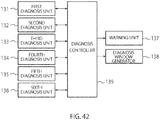
- the second diagnosis unit 132 performs operation confirmation of a plurality of motors.
- the second diagnosis unit 132 performs operation confirmation of the motors 181 to 185 using the photosensor 160 provided at the operation original position of each of the motors 181 to 185. That is, by rotating each of the motors 181 to 185 in a normal direction from the operation original position and then in a reverse direction, it is determined with the photosensor 160 whether each of the motors 181 to 185 returns to the operation original position. If each motor returns to the operation original position, it is determined that the operation is normal. If each motor returns a position shifted from the operation original position, it is determined that the operation is abnormal.
- the diagnosis window generator 138 generates a diagnosis window to be displayed on the display screen of the information processing apparatus 150.
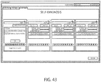
- results of self-diagnosis by the first to sixth diagnosis units 131 to 136 automatically performed at power-on are displayed.
- buttons with which a user arbitrarily selects a self-diagnosis item, a button for starting self-diagnosis, etc. are provided.
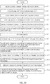
- FIG. 45 is a flowchart showing an example of a self-diagnosis process to be automatically performed by the information processing apparatus 150 when turned on.
- the information processing apparatus 150 performs self-diagnosis with the first diagnosis unit 131 (step S1).
- the diagnosis controller 139 in the information processing apparatus 150 performs communication confirmation with the controller 151 and the current detector 128 in the nucleic acid inspection apparatus 110.
- the controller 151 and the current detector 128 are both mounted on the control substrate 121.
- the information processing apparatus 150 transmits a communication signal to the nucleic acid inspection apparatus 110 via the communication interface substrate 122. If a response signal to the communication signal is received by the information processing apparatus 150 via the communication interface substrate 122 within a predetermined period, it is determined that communication is confirmed to be normal (YES in step S2).
- At least part of the nucleic acid inspection apparatus 110 explained in the embodiment may be configured with hardware or software.
- a program that performs at least part of the functions of the nucleic acid inspection apparatus 110 may be stored in a storage medium such as a flexible disk and CD-ROM, and then installed in a computer to run thereon.
- the storage medium may not be limited to a detachable one such as a magnetic disk and an optical disk but may be a standalone type such as a hard disk and a memory.
Landscapes
- Chemical & Material Sciences (AREA)
- Health & Medical Sciences (AREA)
- Life Sciences & Earth Sciences (AREA)
- General Health & Medical Sciences (AREA)
- Physics & Mathematics (AREA)
- Biochemistry (AREA)
- Analytical Chemistry (AREA)
- Molecular Biology (AREA)
- Chemical Kinetics & Catalysis (AREA)
- General Physics & Mathematics (AREA)
- Immunology (AREA)
- Pathology (AREA)
- Clinical Laboratory Science (AREA)
- Electrochemistry (AREA)
- Engineering & Computer Science (AREA)
- Spectroscopy & Molecular Physics (AREA)
- Quality & Reliability (AREA)
- Dispersion Chemistry (AREA)
- Hematology (AREA)
- Nanotechnology (AREA)
- Apparatus Associated With Microorganisms And Enzymes (AREA)
Abstract
Description
- Embodiments of the present invention relate to a nucleic acid inspection apparatus.
- As for this type of inspection apparatus, an apparatus using a current detection type DNA chip has been known. The current detection type DNA chip has at least one DNA probe having a known base sequence disposed on a plurality of electrodes provided on a substrate. A current that flows when the DNA probe and DNA of an inspection target join together is detected to identify the type of DNA contained in the inspection target.
- However, the conventional current detection type DNA chip has a smaller number of electrodes provided on the substrate, and hence the number of detectable genes is small.
- Moreover, before DNA inspection by the above-described current detection, an amplification process to the DNA contained in the inspection target has to be performed. Conventionally, since after nucleic acid amplification is performed in a container, the container is changed to another one to perform the DNA inspection, it is troublesome for an operator, so that there is a problem that the DNA inspection cannot be performed in a short time.
- The problem to be solved by the present invention is to provide a nucleic acid inspection apparatus capable of performing nucleic acid inspection accurately in a short time, without being troublesome to an operator.
- In a nucleic acid inspection device attached to a nucleic acid inspection apparatus according to the present embodiment, a storage unit stores at least a specimen sample. An amplifier amplifies nucleic acid contained in the specimen sample stored in the storage unit. A first flow passage moves the specimen sample from the storage unit to the amplifier. A detector detects the nucleic acid contained in the specimen sample nucleic-acid amplified by the amplifier. A second flow passage moves the specimen sample from the amplifier to the detector.
- In the nucleic acid inspection apparatus, a first opening/closing unit opens/closes the first flow passage. A second opening/closing unit opens/closes the second flow passage. A heater heats the amplifier. A controller controls the first and second opening/closing units so as to open/close in a predetermined order and controls the heater so as to heat the amplifier in conjunction with opening/closing operations of the first and second opening/closing units.
-
-
FIGs. 1A, 1B and 1C are external views of a nucleic acid inspection system provided with a nucleic acid inspection apparatus according to an embodiment, a unit configuration diagram of the nucleic acid inspection apparatus, and an illustration showing opening and closing of trays provided to the nucleic acid inspection apparatus; -
FIG. 2 is a diagram showing an example of GUI windows displayed on a display screen of an information processing apparatus; -
FIGS. 3A to 3C are illustrations explaining that a DNA probe and a DNA to be inspected are complementary to each other; -
FIGS. 4A to 4D are illustrations explaining a base sequence detection chip; -
FIGS. 5A and 5B are waveform diagrams showing an example of measurement results of an oxidation current detected from the base sequence detection chip; -
FIG. 6 is an external view of a nucleic acid inspection card; -
FIG. 7 is a perspective view showing the configuration of the nucleic acid inspection card; -
FIG. 8A, 8B and 8C are perspective views showing the configuration of four syringes; -
FIG. 9 is a diagram showing a flow passage model of the nucleic acid inspection card; -
FIG. 10 is a sectional view of a valve NOV; -
FIG. 11A and 11B are views showing the configuration of an NC valve; -
FIG. 12 is a diagram showing a flow passage model of the nucleic acid inspection card; -
FIG. 13 is a plan view showing the detailed configuration of an amplification flow passage; -
FIG. 14 is sectional view of a base sequence detection chip using a three-electrode method; -
FIG. 15 is a diagram showing an example of a current detection system of the base sequence detection chip; -
FIG. 16 is a plan view showing the detailed configuration of a DNA chip; -
FIG. 17 is an illustration showing an example of the shape and arrangement of working electrodes in a working electrode group according to a first embodiment; -
FIGS. 18(a) and 18(b) are illustrations showing the shape and arrangement of working electrodes in a working electrode group according to the first embodiment and a comparison example, respectively; -
FIG. 19 is an illustration showing another example of the shape and arrangement of working electrodes in a working electrode group according to the first embodiment; -
FIG. 20 is an illustration explaining the cause of generation of bubbles; -
FIG. 21 is an illustration showing the relationship between a flow passage width and a bubble arrival position; -
FIG. 22 is plan view of the base sequence detection chip of the first embodiment, formed with flow passages; -
FIG. 23 is a block diagram of a control system of a nucleic acid inspection apparatus according to an embodiment; -
FIG. 24 is an illustration of air flow by a frame fan in a nucleic acid inspection; -
FIG. 25 is an external view of a heater and a Peltier device; -
FIG. 26 is a plan view showing the installation locations of five motors, a syringe rod, an NCV rod, an NOV rod, a temperature adjustment supporter, and a probe holder driven by the motors; -
FIG. 27 is a sectional view of a rack gear; -
FIG. 28 is a plan view showing a syringe rod driven by a syringe-axis motor; -
FIG. 29 is a perspective view of a punch; -
FIGS. 30A and 30B are illustrations showing examples of pushing a syringe with punches having different widths; -
FIG. 31 is an illustration showing the relationship between a syringe position shift and a liquid amount from a syringe; -
FIG. 32 is a view of a tapered syringe rod; -
FIG. 33 is a plan view showing an NCV rod driven by an NCV-axis motor; -
FIGS. 34(a), 34(b), and 34(c) are views of tip shapes of fork portions; -
FIG. 35 is a plan view showing an NOV rod driven by an NOV-axis motor; -
FIGS. 36A and 36B are a plan view and a perspective view, respectively, of a temperature adjustment supporter driven by a heater-Peltier-axis motor; -
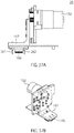
FIGS. 37A and 37B are a plan view and a perspective view, respectively, of a probe holder driven by a probe-axis motor; -
FIG. 38 is an illustration of a positioning pin; -
FIG. 39 is a flowchart showing an example of a drive sequence of each motor by a controller; -
FIG. 40A, 40B, 40C, 40D and 40E are diagrams showing a move state of a liquid on a nucleic acid inspection card; -
FIG. 41 is a block diagram of a control system of a nucleic acid inspection apparatus; -
FIG. 42 is a functional block diagram related to self-diagnosis of an information processing apparatus according to the present embodiment; -
FIG. 43 is an illustration showing an example of a display window of a self-diagnosis result; -
FIG. 44 is a display example of a diagnosis window on which a user arbitrarily selects a self-diagnosis item; and -
FIG. 45 is a flowchart showing an example of a self-diagnosis process to be automatically performed by an information processing apparatus when turned on. - An embodiment of the present invention will be explained with reference to the drawings. The following embodiment will be explained mainly with unique configurations and operations in a nucleic acid inspection apparatus. However, the nucleic acid inspection apparatus may have configurations and operations, the explanation thereof being omitted in the following explanation. These omitted configurations and operations fall within the scope of the present embodiment.
-
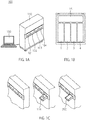
FIG. 1A is an external view of a nucleic acid inspection system provided with a nucleic acid inspection apparatus according to the present embodiment.FIG. 1B is a unit configuration diagram of the nucleic acid inspection apparatus.FIG. 1C an illustration showing opening and closing of trays provided to the nucleic acid inspection apparatus. As shown inFIG.1A , a nucleicacid inspection system 100 is provided with a nucleicacid inspection apparatus 110 and aninformation processing apparatus 150. The nucleicacid inspection apparatus 110 is, as described later, to inspect nucleic acid contained in a specimen sample. Theinformation processing apparatus 150 is to instruct inspection conditions, inspection start, etc. to the nucleicacid inspection apparatus 110, analyze an inspection result by the nucleicacid inspection apparatus 110, and display the result. - The nucleic
acid inspection apparatus 110 according to the present embodiment has a future of inspecting a plurality of specimen samples at a time. In the example ofFIG. 1B , fourinspection units control substrate 15 are provided so as to inspect four kinds of specimen samples at a time. Theinspection units control substrate 15 to perform nucleic acid inspection of the respective specimen samples at different timings. - The respective specimen samples are taken in and out from the nucleic
acid inspection apparatus 110 throughshutters FIG. 1C are provided to theinspection units acid inspection cards 700 are placed on thetrays - The nucleic
acid inspection apparatus 110 according to the present embodiment itself does not have a setting input function and a display function. Therefore, the compactness and apparatus cost reduction of the nucleicacid inspection apparatus 110 can be achieved. Setting input to the nucleicacid inspection apparatus 110, analysis of a result of nucleic acid inspection, etc. are performed by theinformation processing apparatus 150 connected to the nucleicacid inspection apparatus 110. Theinformation processing apparatus 150 can be configured with a general-purpose computer such as a PC on the market, and hence is implemented at a low cost and a maintenance cost is not so high. The nucleicacid inspection apparatus 110 and theinformation processing apparatus 150 transmit and receive several kinds of information via a genera-purpose communication interface, such as, a USB (Universal Serial Bus). As described above, by configuring the nucleic acid inspection system with the nucleicacid inspection apparatus 110 and theinformation processing apparatus 150, maintenance of the nucleicacid inspection apparatus 110 is made easy, and setting input to the nucleicacid inspection apparatus 110 and analysis and display of a result of nucleic acid inspection are easily performed. -
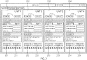
FIG. 2 is a diagram showing an example of GUI windows displayed on a display screen of theinformation processing apparatus 150. InGUI windows FIG. 2 , setting input items of four inspection units are displayed respectively. In accordance with theGUI windows inspection units information processing apparatus 150 to the nucleicacid inspection apparatus 110, as required, and set into the nucleicacid inspection apparatus 110. In theGUI windows selection buttons inspection units buttons display areas acid inspection apparatus 110. Theinformation processing apparatus 150 and the nucleicacid inspection apparatus 110 transmit and receive several kinds of information by wired or non-wired communication. Information selected by theselection buttons inspection start buttons acid inspection apparatus 110 and inspection progress information at the nucleicacid inspection apparatus 110 is periodically transmitted from the nucleicacid inspection apparatus 110 to theinformation processing apparatus 150. -
GUI windows information processing apparatus 150 can be arbitrarily modified by software. Therefore, theGUI windows FIG. 2 are merely an example. By updating the software, it is possible to provide user-friendly GUI windows, easily compatible with new types of nucleic acid inspection. - Before explaining the nucleic
acid inspection apparatus 110 according to the present embodiment in detail, the basic principle of nucleic acid inspection adopted by the present embodiment will be explained. - DNA has a double-stranded structure that has two strands each with a sequence of A (adenine), T (thymine), G (guanine), and C (cytosine), joined to each other. The double-stranded structure is a joint structure of a specific combination of the bases A, T, G, and C. Since a piece of DNA can be easily synthesized, on a
DNA chip 500, a known single-stranded base sequence is fixed on an electrode, as a probe. DNA of a specimen sample is also modified to have a single strand and is reacted with the DNA probe fixed on the electrode. If the sequence of the DNA of the specimen sample is complementary to the sequence of the DNA probe, the sequences join to each other to become a double-stranded structure. For example, as shown inFIG. 3A , when the DNA probe has a sequence in order of TAGAC, if the DNA of the specimen sample has a sequence in order of ATCTG (FIG. 3B ), since the sequences are complementary to each other, these pieces of single-stranded DNA shown inFIG. 3C join to each other to become a double-stranded structure. Accordingly, it is referred to as hybridization that the base sequence of the specimen sample joins to the complementary base sequence of the DNA probe to become a double-stranded structure. - As shown in
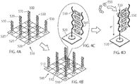
FIG. 4A , theDNA chip 500 is fabricated in a manner that, for example, a plurality ofelectrodes 520 are arranged apart from one another on asubstrate 510 made of, for example, glass or silicon andDNA probes 530 having different sequences are fixed on therespective electrodes 520. On thisDNA chip 500, a nucleic-acid amplified specimen sample is made flown. In this occasion, if aDNA probe 530 having a base sequence complementary to the base sequence in the specimen sample is present on theDNA chip 500, both join to each other to cause hybridization to create a double-stranded DNA (FIGS. 4B and 4C ). On the other hand, if aDNA probe 530 having a base sequence complementary to the base sequence in the specimen sample is not present on theDNA chip 500, hybridization does not occur. Thereafter, theDNA chip 500 is washed and a reagent (solution) containing anintercalating agent 550 is made flown on theDNA chip 500. Then, theintercalating agent 550 joins to the hybridized double-strandedDNA probe 530. In this state, when a voltage is applied to theDNA chip 500, an oxidation current of theintercalating agent 550 flows to theelectrode 520 on which the hybridized double-strandedDNA probe 530 is fixed (FIG. 4D ). - An example of this oxidation current, that is, a signal from the electrode on which hybridization has occurred is shown in
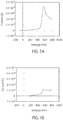
FIG.5A . An example of a signal from an electrode on which no hybridization occurs is shown inFIG.5B . As understood fromFIG. 5A , when the voltage applied to theDNA chip 500 is increased, the oxidation current suddenly increases at a voltage of about 500 mV. In contrast, the signal value from the electrode on which no hybridization occurs increases a little bit when the voltage applied to theDNA chip 500 reaches about 500 mV, however, compared to the case shown inFIG. 5A , the degree of increase is small. In this way, by determining from which electrode a current is detected, the DNA sequence of the specimen sample can be identified. - The nucleic
acid inspection apparatus 110 according to the present embodiment detects, in accordance with the above-describe basic principle, whether there is an oxidation current flowing to the electrodes on theDNA chip 500 to inspect the DNA of the specimen sample. - The target of the specimen-sample nucleic acid inspection of the present embodiment is not necessarily limited to DNA (Deoxyribonucleic Acid), which is applicable to several kinds of nucleic acid, such as RNA (ribonucleic Acid), oligonucleotide, and polynucleotide. Nevertheless, in the following explanation, an example of inspection of DNA in a specimen sample will be explained.
- In the nucleic
acid inspection apparatus 110 according to the present embodiment, a specimen sample is put into a detachable nucleicacid inspection card 700 to perform inspection by the nucleicacid inspection apparatus 110. -
FIG. 6 is an external view of the nucleicacid inspection card 700. The nucleicacid inspection card 700 is a detachable thin rectangular body, which is configured with acap 750, acover 740, anupper plate 730, a packing 720, aDNA chip 500, and alower plate 710. Among them, thecap 750, thecover 740, theupper plate 730, and thelower plate 710 are formed with a hard resin member such as PC (polycarbonate), the packing 720 is formed with an elastic resin member such as elastomer, and theDNA chip 500 is formed with a transparent base such as glass. - As described above, the nucleic
acid inspection card 700 can be assembled with just six parts, a material cost and the number of fabrication steps can be reduced to provide the nucleicacid inspection card 700 at a low price. Especially, since the nucleicacid inspection card 700 according to the present embodiment is intended for disposal use, it is a big advantage that the nucleicacid inspection card 700 can be provided at a low price. -
FIG. 7 is a view explaining assembling steps of the nucleicacid inspection card 700. On thelower plate 710, theDNA chip 500 is disposed and, on theDNA chip 500, the packing 720 is disposed. On thelower plate 710, as shown inFIG. 8A , four concave portions 711C1, 711C2, 711C3, and 711C4 are formed by integral molding, so as to correspond to the locations of four syringes. On the packing 720, as shown inFIG. 8B , four dome-like convex portions 721C1, 721C2, 721C3, and 721C4 are formed by integral molding, so as to correspond to the locations of the four syringes. When packing 720 is attached on thelower plate 710, as shown inFIG. 8C , the concave portions and the convex portions are arranged to face each other to form four syringes 710C1, 710C2, 710C3, and 710C4, as storage units. In these syringes 710C1, 710C2, 710C3, and 710C4, as described later, a specimen sample, a cleaning solution, and the like are separately stored. - On the
lower plate 710, as shown inFIGS. 7 and8A , ditches that become flow passages through which liquids flow are formed in the direction from the syringes 710C1, 710C2, 710C3, and 710C4 to theDNA chip 500. The packing 720 also have ditches formed so as to match the location of the ditches of thelower plate 710. Therefore, when the packing 720 is attached to thelower plate 710, flow passages are formed with the ditches arranged to face each other. Although, the upper surface of theDNA chip 500 to which thelower plate 710 is attached is a flat surface, since the ditches are formed in the locations on the packing 720 that faces theDNA chip 500, when the packing 720 is attached to thelower plate 710, an inspection flow passage (inspection unit) 712 is formed on theDNA chip 500. Thisinspection flow passage 712 is connected to the flow passages formed with the ditches of thelower plate 710 and the ditches of the packing 720. - Subsequently, the
upper plate 730 is attached on thelower plate 710. Part of theupper plate 730 is an outer surface of the nucleicacid inspection card 700. As shown inFIGS. 6 and7 , two throughholes DNA chip 500. The throughholes current probe 186 from above to make thecurrent probe 186 contact with the electrodes on theDNA chip 500. - On the
upper plate 730, two throughholes acid inspection card 700 from a flow passage that is connected to theamplification flow passage 710f. The throughholes - Subsequently, the
cover 740 is attached to cover part of theupper plate 730. As shown inFIGS. 6 and7 , theupper plate 730 and thecover 740 are provided with four throughholes holes first rods syringe rod 20 from above to push out liquids in the syringes 710C1, 710C2, 710C3, and 710C4 to the flow passages. - The
upper plate 730 and thecover 740 are provided with four through holes 720d1, 720d2, 720d3, and 720d4 so as to match injection holes of the four syringes 710C1, 710C2, 710C3, 710C4. Via the through holes 720d1, 720d2, 720d3, and 720d4, liquids are injected into the four syringes 710C1, 710C2, 710C3, 710C4. In more specifically, a specimen sample, a first cleaning solution, an intercalating agent, and a second cleaning solution are injected into the syringes 710C1, 710C2, 710C3, 710C4, respectively, via the separate injection holes 710d1, 710d2, 710d3, and 710d4. Here, the specimen sample is, for example, a liquid containing any one of enzyme, triphosphate deoxyribonucleotide (dNTP), a surfactant, magnesium chloride, and ammonium sulfate. The first cleaning solution is, for example, a liquid containing sodium citrate or sodium chloride. The intercalating agent is, for example, a liquid containing Hoechst 33258 (Hoechst 33258). The second cleaning solution is, for example, a liquid containing sodium citrate or sodium chloride. - Moreover, the
upper plate 730 and thecover 740 are provided with four syringes 710C1, 710C2, 710C3, and 710C4, and through holes 710h1, 710h2, 710h3, and 710h4 for four NC (Normally Close) valves 710v1, 710v2, 710v3, and 710V4 that shut off flow passages connect to the respective syringes 710C1, 710C2, 710C3, and 710C4. The through holes 710h1, 710h2, 710h3, and 710h4 are used for inserting second rods 221 (first opening/closing unit), 222 (fourth opening/closing unit), 223 (fifth opening/closing unit), and 224 (sixth opening/closing unit) to open/close the NC valves 710v1, 710v2, 710v3, and 710V4, respectively. - Subsequently, a
cap 750 is attached to the cutaway of thecover 740 with a hinge to complete the nucleicacid inspection card 700. Thecap 750 is provided for a user himself or herself to inject the specimen sample from the injection hole 710d1. The first cleaning solution, the second cleaning solution, and the intercalating agent, other than the specimen sample, have already been injected into the associated syringes, in advance, at the stage of assembling the nucleicacid inspection card 700. What the user injects thereafter is the specimen sample only. Therefore, thecap 750 for covering the injection hole 710d1 for the specimen sample is provided. - As described above, the nucleic
acid inspection card 700 according to the present embodiment, is provided with the plurality of syringes 710C1, 710C2, 710C3, and 710C4 for separately storing the specimen sample and the like, theamplification flow passage 710f for nucleic acid amplification, and theinspection flow passage 712 for DNA inspection, capable of nucleic acid amplification and DNA inspection with one card without replacing the specimen sample, reagent, etc., thus achieving automatic DNA inspection. -
FIG. 9 is a plan view of the nucleicacid inspection card 700 from which the cap, thecover 740, and theupper plate 730 have been detached. As shown inFIG. 9 , the four syringes 710C1, 710C2, 710C3, and 710C4 are arranged in the lateral direction on one side of the nucleicacid inspection card 700 in the longitudinal direction. The leftmost syringe (first storage unit chamber) 710C1 stores the specimen sample. The syringe (second storage chamber) 710C2, the second one from the leftmost, stores the first cleaning solution. The syringe (fourth storage chamber) 710C3, the second one from the rightmost, stores the intercalating agent. The rightmost syringe (third storage chamber) 710C4 stores the second cleaning solution. - On the side of the syringes 710C1, 710C2, 710C3, and 710C4, the injection holes 710d1, 710d2, 710d3, and 710d4 for injecting liquids into the syringes 710C1, 710C2, 710C3, and 710C4, respectively, and exhaust holes 710e1, 710e2, 710e3, and 710e4 for releasing air in the syringes 710C1, 710C2, 710C3, and 710C4, respectively, are provided.
- On the center of the nucleic
acid inspection card 700 in the longitudinal direction, theamplification flow passage 710f for amplifying nucleic acid in the specimen sample is provided. Theamplification flow passage 710f and the syringe (710C1) for storing the specimen sample are connected with a flow passage (first flow passage). This flow passage is branched off half way and, to the branched flow passage (third flow passage), the syringe (710C2) for storing the first cleaning solution is connected. Moreover, theamplification flow passage 710f and theinspection flow passage 712 in theDNA chip 500 are connected to each other with a flow passage (second flow passage). Therefore, the specimen sample that is nucleic-acid amplified in theamplification flow passage 710f can be pushed out by the first cleaning solution, and hence, without complicated valve control, the specimen sample can be moved to theinspection flow passage 712 on theDNA chip 500. - The second flow passage is branched off half way, and, to the branched flow passage (fourth flow passage), the syringe (710C4) for storing the second cleaning solution is connected. Moreover, the flow passage (fourth flow passage) is branched off half way, and, to the branched flow passage (fifth flow passage), the syringe (710C3) for storing the intercalating agent is connected. Therefore, the second cleaning solution accumulated in the
inspection flow passage 712 can be pushed out by the intercalating agent. - On both sides of the
amplification flow passage 710f, the NO valves 720a1 and 7120a2 are provided. The NO valves 720a1 and 7120a2 are normally opened so that a liquid can freely flows between the flow passage connected to theamplification flow passage 710f and theamplification flow passage 710f. When the NO valves 720a1 and 7120a2 are closed, theamplification flow passage 710f and the flow passage connected to theamplification flow passage 710f are shut off so that it does not occur that the liquid in theamplification flow passage 710f flows back into the syringes 710C1, 710C2, 710C3, and 710C4 though the flow passage, or flows in the inspection flow passage712 of theDNA chip 500. In the present embodiment, during the nucleic acid amplification in theamplification flow passage 710f, the NO valves 720a1 and 720a2 are closed, so that the nucleic-acid amplified specimen sample is not mixed with the specimen sample in the syringe (710C1). -
FIG. 10 is a schematic sectional view showing the configuration of the NO valve. The packing 720 disposed on thelower plate 710 has a dome-like convex portion on the location where the NO valve 720a1 is formed and a flow passage is formed within the convex portion. When the convex portion is pushed from above with thesyringe rod 251, the flow passage is closed. The NO valve 720a2 is also formed in the same manner as described above. - Returning to
FIG. 9 , in the vicinity of connecting points of the syringes 710C1, 710C2, 710C3, and 710C4, and the flow passages, NC valves 710v1, 710v2, 710v3, and 710V4 are provided. Since there are four syringes 710C1, 710C2, 710C3, and 710C4, four NC valves 710v1, 710v2, 710v3, and 710V4 are provided. The NC valves 710v1, 710v2, 710v3, and 710V4 are normally closed to shut off the syringes 710C1, 710C2, 710C3, and 710C4, and the flow passages connected thereto. When the NC valves 710v1, 710v2, 710v3, and 710V4 are opened, the syringes 710C1, 710C2, 710C3, and 710C4, and the flow passages are connected, so that liquids in the syringes 710C1, 710C2, 710C3, and 710C4 associated with the opened NC valves 710v1, 710v2, 710v3, and 710V4 flow into the flow passages connected to the syringes 710C1, 710C2, 710C3, and 710C4. -
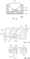
FIG. 11 is a view showing the configuration of the NC valve.FIG. 11A is a perspective view andFIG. 11B is a sectional taken on line A-A ofFIG. 11A . The NC valves 710v1, 710v2, 710v3, and 710V4 are cantilevers formed with acover 740. The base portion of each cantilever is supported by thecover 740 while the top portion of the cantilever is movable and the top portion is energized in the direction to close each flow passage. Therefore, normally, the flow passages are closed. By pushing up around the top portions of the cantilevers withfork portions NCV rod 23 at the top side, the top portions of the cantilevers are raised to open the flow passages. - Returning to
FIG. 9 , on the opposite side to the locations where the four syringes 710C1, 710C2, 710C3, and 710C4 are arranged having the amplification flow passage710f of the nucleicacid inspection card 700 located therebetween, in the lateral direction, a waste liquid tank 711g1, theDNA chip 500, and a waste liquid tank 711g2 are arranged. The specimen sample nucleic-acid amplified in theamplification flow passage 710f passes through the flow passage and flows into theinspection flow passage 712 on theDNA chip 500. Thereafter, the first cleaning solution flows into theinspection flow passage 712 and the specimen sample in theinspection flow passage 712 moves to the waste liquid tank. Subsequently, when the second cleaning solution flows into theinspection flow passage 712, the first cleaning solution moves to the waste liquid tank, further subsequently, when the intercalating agent flows into theinspection flow passage 712, the second cleaning solution moves to the waste liquid tank. -
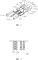
FIG. 12 is a diagram showing a flow passage model of the nucleicacid inspection card 700. The specimen sample, the first cleaning solution, the intercalating agent, and the second cleaning solution are injected from the injection holes 710d1, 710d2, 710d3, and 710d4, respectively, and stored in the syringes 710C1, 710C2, 710C3, and 710C4, respectively. When the NC valve 710v1 is opened, the specimen sample stored in the syringe (710C1) passes through the flow passage and reaches theamplification flow passage 710f. Then the NO valves 720a1 and 7120a2 are closed to perform nucleic acid amplification. Thereafter, when the NC valve 710v2, and the NO valves 720a1 and 7120a2 are opened, the first cleaning solution stored in the syringe (710C2) reaches theamplification flow passage 710f. The specimen sample accumulated so far in theamplification flow passage 710f passes through the flow passage, as the specimen sample is pushed out by the first cleaning solution, and reaches theinspection flow passage 712 on theDNA chip 500. Thereafter, when the NC valve 710v4 is opened, the second cleaning solution stored in the syringe (710C4) passes through the flow passage to reach theinspection flow passage 712 on theDNA chip 500. The specimen sample accumulated so far in theinspection flow passage 712 moves to the waste liquid tanks 711g1 and 711g2. Thereafter, when the NC valve 710v3 is opened, the intercalating agent stored in the syringe 710C3 passes through the flow passage to reach theinspection flow passage 712 on theDNA chip 500. The second cleaning solution accumulated so far in theinspection flow passage 712 moves to the waste liquid tanks 711g1 and 711g2. -
FIG. 13 is a plan view showing the detailed configuration of theamplification flow passage 710f. As shown inFIG. 13 , theamplification flow passage 710f meanders so that a liquid flows slowly. For nucleic acid amplification, for example, the LAMP (Loop-Mediated Isothermal Amplification) method is used. In theamplification flow passage 710f, a primer that joins part of nucleic acid in the specimen sample to be amplified is placed in advance. When the specimen sample is inject into theamplification flow passage 710f and heated to a predetermined temperature, nucleic acid amplification can be completed in mere several ten minutes. Amplified products by nucleic acid amplification include, not only double stands of DNA, but also a single strand. In theinspection flow passage 712 on theDNA chip 500, which will be described later, the single strand created by nucleic acid amplification is used for current detection. - The method of nucleic acid amplification according to the present embodiment is not necessarily be limited to the LAMP method. Several kinds of nucleic acid amplification methods, such as, the PCR (Polymerase Chain Reaction) method, may be used.
- In the
amplification flow passage 710f, there are a plurality of wells in which liquids are temporary accumulated at an even interval. The inventor of the present invention firstly found that, by providing such wells, multi-amplification to amplify different pieces of DNA can be performed. The inventor of the present invention found that the gap between the wells is preferably 4 mm or more along the flow passage. - Subsequently, one example of current detection in the
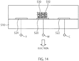
DNA chip 500 will be explained with respect toFIGS. 14 and15 . For the current detection, for example, a three-electrode method is used. In theDNA chip 500 for which three-electrode method is used, for example, as shown inFIG. 14 , on thesubstrate 510, a workingelectrode 520, acounter electrode 522, and areference electrode 524 are provided. The workingelectrode 520, thecounter electrode 522, and thereference electrode 524 are provided apart from one another. To the workingelectrode 520, at least oneDNA probe 530 having the identical sequence (three inFIG. 14 ) is fixed and connected to a terminal W provided on thesubstrate 510. Although, in order to make the explanation easy, only one workingelectrode 520 is shown, generally, a plurality of them are provided. Thecounter electrode 522 is connected to a terminal C provided on thesubstrate 510. Thereference electrode 524 is connected to a terminal R provided on thesubstrate 510. - One example of a current detection system for the
DNA chip 500 configured as described above is shown inFIG. 15 . Acurrent detection system 600 shown inFIG. 15 is a potentiostat in which, by feed-backing a voltage of thereference electrode 524 to the input of thecounter electrode 522, a desired voltage is applied in a solution irrespective of variation in several conditions of the electrodes, the solution, etc., in thesubstrate 510. - The
potentiostat 600 varies the voltage of thecounter electrode 522 so that the voltage of the reference electrode to the workingelectrode 520 is set in predetermined characteristics, to electrochemically measure an oxidation current due to the intercalating agent. - The working
electrode 520 is an electrode to which the DNA theprobe 530 is fixed and is an electrode for detecting a reaction current in the DNA chip (base sequence detection chip) 500. Thecounter electrode 522 is an electrode to apply a predetermined voltage between itself and the workingelectrode 520 to supply a current in the base sequence detection chip. Thereference electrode 524 is an electrode to feed-back the voltage of thereference electrode 524 to thecounter electrode 522 in order to control the voltage between thereference electrode 524 and the workingelectrode 520 to be in predetermined voltage characteristics. In this way, the voltage by thecounter electrode 522 is controlled to perform highly accurate oxidation current detection irrespective of several detection conditions in the base sequence detection chip. -
Voltage generation circuitry 610 for generating a voltage pattern for detecting a current flowing between the electrodes is connected to an inverting input terminal of an invertingamplifier 612 for controlling the reference voltage of thereference electrode 524 via awiring 612b. - The
voltage generation circuitry 610 is circuitry to generate a voltage pattern by converting a digital signal input from a control mechanism of a base sequence detection control apparatus (not shown) to an analog signal, provided with a DA converter. - To the
wiring 612b, a resistor Rs is connected. In the invertingamplifier 612, a non-inverting input terminal is grounded and an output terminal is connected to awiring 602a. Thewiring 612b on the side of the non-inverting input terminal of theinversion amplifier 612 and thewiring 602a on the output terminal side thereof are connected by awiring 612a. To thewiring 612a,protection circuitry 620 composed of a feed-back resistor Rf' and switch SWf is provided. - The
wiring 602a is connected to the terminal C. The terminal C is connected to thecounter electrode 522 on theDNA chip 500. When a plurality ofcounter electrodes 522 are provided, the terminal C is connected to them in parallel. In this way, with one voltage pattern, a voltage can be applied to a plurality of counter electrodes at the same time. To thewiring 602a, a switch SW0 for on-off control of voltage application to the terminal C is provided. - By means of the
protection circuitry 620 provided to theinversion amplifier 612, an excess voltage is not applied to thecounter electrode 522. Therefore, there is no likelihood that the excess voltage is applied to thecounter electrode 522 at the current detection time, a solution is electrolyzed, and a bad effect may be given to the oxidation current detection, thereby conducting stable measurement. - A terminal R is connected to a non-inverting input terminal of a
voltage flower amplifier 613 with awiring 603a. An inverting input terminal of thevoltage flower amplifier 613 is short-circuited bywirings voltage flower amplifier 613. To thewiring 613b, a resistor Rf is provided and the resistor Rf is connected, at its one terminal, to the wiring 513b and connected, at the other terminal, between a resistor Rs and the cross point of the wirings 612a and 612b. In this way, the voltage pattern generated by thevoltage generation circuitry 610 and the fed-back voltage of thereference electrode 524 are input to thevoltage inverting amplifier 612, based on the output which is obtained by amplifying such a voltage by inversion amplification, to control the voltage of thecounter electrode 522. - A terminal W is connected to an inverting input terminal W of a
trance impedance amplifier 611 with awiring 601a. In thetrance impedance amplifier 611, a non-inverting input terminal is grounded and an output terminal is connected to awiring 611b and to the inverting input terminal via a wiring611a. To thewiring 611a, a resistor Rw is provided. When a voltage and a current at a terminal O on the output side of thetrance impedance amplifier 611 are Vw and Iw, respectively, Vw = Iw × Rw is given. An electrochemical signal obtained from the terminal O is output to the control mechanism of the base sequence detection control apparatus (not shown). - Since there is a plurality of working
electrodes 520, a plurality of terminals W and terminals O are provided for the workingelectrodes 520. The outputs of the terminals O are switched by a signal switch, which will be described later, and are converted by AD conversion, so that electrochemical signals from the respective working electrodes can be obtained as digital values. The circuitry, such as thetrance impedance amplifier 611, between the terminals W and O may be shared by the plurality of working electrodes. In this case, a signal switch for switching the wirings from the plurality of terminals W may be provided to thewiring 601a. - Using the
potentiostat 600 having such configuration, current measurement in the base sequence detection chip is performed as follows. - 1. Firstly, using the
potentiostat 600, the potential of the workingelectrode 520 is made constant with respect to the potential of thereference electrode 524. - 2. The working
electrode 520 electrolyzes the intercalating agent on theelectrode 520. - 3. The current required for maintaining electrolysis on the working
electrode 520 is a current Ic flowing from thecounter electrode 522. - 4. In this occasion, the
potentiostat 600 accurately measures a current flowing between the workingelectrode 520 and thecounter electrode 522. In other words, almost no current flows to thereference electrode 524. -
FIG. 16 is a plan view showing the detailed configuration of theDNA chip 500. TheDNA chip 500 shown inFIG. 16 is provided with 40 workingelectrode groups 5201 to 52040,counter electrodes reference electrode 524, on a solid-phase substrate 51. Thecounter electrodes reference electrode 524 is denoted by RE. The solid-phase substrate 510 is, for example, a glass substrate, a silicon substrate, etc. - The 40 working
electrode groups 5201 to 52040 are aligned as being divided into a first to a fourth portion. The first portion is composed of 10 workingelectrode groups 5201 to 52010, aligned from left to right in the drawing. The second portion is composed of 10 workingelectrode groups 52011 to 52020, arranged beneath the first portion in the drawing and aligned from right to left in the drawing. The third portion is composed of 10 workingelectrode groups 52021 to 52030, arranged beneath the second portion in the drawing and aligned from left to right in the drawing. The fourth portion is composed of 10 workingelectrode groups 52031 to 52040, arranged beneath the third portion in the drawing and aligned from right to left in the drawing. - Each working electrode group 520i (i = 1, ···, 40) has three working electrodes provided apart from one another. To the working electrodes, DNA probes having the identical DNA sequence are fixed. Each working electrode is, for example, formed with gold.
- The
counter electrode 522a has a U-shape. One end of the U-shape is disposed in the vicinity of the workingelectrode group 52010 of the first portion. The other end of the U-shape is disposed in the vicinity of the workingelectrode group 52011 of the second portion. Thecounter electrode 522b has a U-shape. One end of the U-shape is disposed in the vicinity of the workingelectrode group 52030 of the third portion. The other end of the U-shape is disposed in the vicinity of the workingelectrode group 52031 of the fourth portion. - The
reference electrode 524 has a U-shape. One end of the U-shape is disposed in the vicinity of the workingelectrode group 52020 of the second portion. The other end of the U-shape is disposed in the vicinity of the workingelectrode group 52021 of the third portion. - To the
substrate 510, terminals W electrically connected to respective working electrodes of each working electrode group 520i (i = 1, ···, 40) is provided. With these terminals W, acurrent probe 186 is made contact. - Moreover, to the
substrate 510,C terminals R terminals Y terminals conduction detection terminals 58 are provided further. TheC terminal 523a is electrically connected to thecounter electrode 522a. TheC terminal 523b is electrically connected to thecounter electrode 522b. TheR terminals reference electrode 524.X terminals DNA chip 500, which are terminals for detecting whether theDNA chip 500 is in a conductive state by applying a voltage between theterminals Y terminals DNA chip 500, which are terminals for detecting whether theDNA chip 500 is in a conductive state by applying a voltage between theterminals conduction detection terminals 580 are provided in association with the working electrodes of the workingelectrode groups 5201 to 52040, and eachconduction detection terminal 580 is connected to the associated working electrode. By applying a voltage between eachconduction detection terminal 580 and the terminal W electrically connected to the associated working electrode, it is detected whether the above-mentioned associated working electrode and the above-mentioned terminal W are in a conductive state therebetween. The above-mentioned terminals are, as shown inFIG. 6 , provided in groups above and below in the drawing, to have the working electrode group 520i (i =1, ···, 40) therebetween. - The
DNA chip 500 is attached to the nucleicacid inspection card 700. When attached, a flow passage is formed on the first portion so that a reagent containing an intercalating agent flows from the workingelectrode group 5201 to the workingelectrode 52010. Also on thecounter electrode 522a, a flow passage is formed so that the reagent flows from the workingelectrode group 52010 to the workingelectrode 52011. A flow passage is formed on the second portion so that the reagent flows from the workingelectrode group 52011 to the workingelectrode 52020. Also on thereference electrode 524, a flow passage is formed so that the reagent flows from the workingelectrode group 52020 to the workingelectrode 52021. A flow passage is formed on the third portion so that the reagent flows from the workingelectrode group 52021 to the workingelectrode 52030. Also on thecounter electrode 522b, a flow passage is formed so that the reagent flows from the workingelectrode group 52030 to the workingelectrode 52031. A flow passage is formed on the fourth portion so that the reagent flows from the workingelectrode group 52031 to the workingelectrode 52040. The flow passages are formed with an area of theDNA chip 500 where the first to fourth portions of the workingelectrode group 520i, the counter electrode, and the reference electrode are formed, and the upper cover for coving these areas. As the upper cover, for example, a packing of the base sequence detection apparatus is used. - The reagent containing the intercalating agent passes through the flow passage on the first portion, the flow passage on the
counter electrode 522a, the flow passage on the second portion, the flow passage on thereference electrode 524, the flow passage on the third portion, the flow passage on thecounter electrode 522b, and the flow passage on the fourth portion, in this order. - One example of three working electrodes in each working electrode group 520i (i = 1, ···, 40) of the
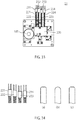
DNA chip 500 according to the present embodiment is shown inFIG. 17 . Each workingelectrode 520 has a shape of a race track, having semicircles each connected to a pair of facing sides of a rectangular. The three workingelectrodes 520 may have an oval shape. To the three workingelectrodes 520, DNA probes having the identical DNA sequence are fixed, respectively. These DNA probes are fixed on the respective workingelectrodes 520 by dropping a liquid containing the above-mentioned identical DNA sequence onto a working electrode group including the three workingelectrodes 520. Then, aspot 525 of the above-mentioned liquid is formed in the area that includes the three workingelectrodes 520. The number of working electrodes in each working electrode group is preferably an odd number. This is because, to the working electrodes in each working electrode group, the DNA probes having the identical sequence are fixed and the presence of an oxidation current detected from each working electrode is decided by majority. - The above-mentioned three working electrodes are arranged in parallel in the direction in which the reagent containing the intercalating agent flows, that is the direction from left to right in
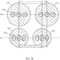
FIG. 17 . Each workingelectrode 520 has a shape with a short axis in the direction in which the reagent flows and a long axis in the direction orthogonal to the direction in which the reagent flows. Having such shape and arrangement, compared to the case where each workingelectrode 520 has the shape of circle in a comparison example shown inFIG. 18(b) , it is possible to have aspot 525 with a small diameter and a short center-to-center distance betweenspots 525 next to each other, in the present embodiment shown inFIG. 18(a) . With this arrangement, a larger number of working electrode groups can be aligned on theDNA chip 500, so that it is possible to increase number of detectable genes. - Moreover, in order to arrange a larger number of working electrode groups on the
DNA chip 500, it is desirable to satisfy the following conditions (1) and (4). The total width of three workingelectrodes 520 is denoted as a, the short-axis width and the long-axis width of each workingelectrode 520 are denoted as x and y, respectively, the center-to-center distance and the shortest distance between the working electrodes next to each other among the three workingelectrodes 520 are denoted as b and c, respectively, and the radius of eachspot 525 is denoted as r. - In the present embodiment, it is desirable that the total width a of the three working
electrodes 520 is 90% or less of the diameter of eachspot 525. That is, it is desirable to satisfy the condition
electrodes 520 to be arranged in thespot 525. - Moreover, it is desirable to satisfy the condition

- Furthermore, it is desirable to satisfy the condition

- Moreover, it is desirable to satisfy the condition

electrode 520, for example, c > 10 nm. The condition (4) is a condition for the three workingelectrodes 520 not to be overlap with one another. - Subsequently, another example of three working electrodes in each working electrode group 520i (i = 1, ···, 40) of the
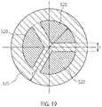
DNA chip 500 of the present embodiment is shown inFIG. 19 . In the other example, three workingelectrodes 520 have a fan-like shape arranged in concentric with one another. Moreover, the three workingelectrodes 520 are arranged in such a manner that the center of each working electrode is located on the vertex of an equilateral triangle. One of the vertexes of the equilateral triangle is located on the lateral axis of thespot 525 on the side where a reagent containing an intercalating agent flows into the left side inFIG. 19 . - As described above, by forming the three working
electrodes 520 to have a fan-like shape and arranging the three workingelectrodes 520 in such a manner that the center of each working electrode is located on the vertex of the equilateral triangle, it is possible to have a smaller diameter of thespot 525 and a shorter center-to-center distance between the workingelectrodes 520 next to each other. Accordingly, a larger number of working electrode groups can be arranged on theDNA chip 500, so that it is possible to increase the number of detectable genes. - Furthermore, in order to arrange a larger number of working electrode groups on the
DNA chip 500, it is desirable to satisfy the following conditions (5) to (6). The maximum radius of the three workingelectrodes 520 is denoted as a, the shortest distance between the working electrodes next to each other among the three workingelectrodes 520 is denoted as c, and the radius of thespot 525 is denoted as r. - In the other example shown in
FIG.19 , it is desirable that the maximum radius a of the three workingelectrodes 520 is 90% or less of the radius of thespot 525. That is, it is desirable to satisfy the condition
electrodes 520 to be arranged in thespot 525. - Moreover, it is desirable to satisfy the condition

electrode 520, for example, c > 10 nm. - As explained above, according to the present embodiment, even using a smaller substrate, it is possible to increase the number of working electrodes. By fixing DNA probes having different DNA sequences to the respective working electrode groups, it is possible to increase the number of detectable genes.
- Detection of a DNA sequence is performed by making a reagent containing an intercalating agent flow into a detection flow passage formed on the
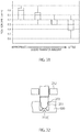
DNA chip 500. When the reagent flows, if there is a babble on an electrode, accurate current detection cannot be performed, so that it is difficult to accurately detect the DNA sequence. The inventors of the present invention diligently studied the cause of generation of the bubble in a flow passage on an electrode of theDNA chip 500. As a result, the following are found. The inlet of theDNA chip 500 to which the reagent flows into is formed on anupper cover 770 in an almost vertical direction to theDNA chip 500, as shown inFIG. 20 . Because of this, the reagent flows, as shown by anarrow 765a, from aninlet 760a toward into theDNA chip 500 in a vertically downward direction. Therefore,stagnation 790 is generated in an area of aflow passage 780 just under the inlet, a babble is generated by the stagnation, and this babble reaches an area over anelectrode 520 through aflow passage 780, as shown by anarrow 765b. - The inventors conducted an experiment to study how much distance the babble is sent from the area just under the inlet into the flow passage. The result is shown in
FIG. 21 . As understood fromFIG. 21 , when the flow passage width is 1 mm, the babble arrival position is 1. 6 times the flow passage width, and when the flow passage width is 1. 2 mm, the babble arrival position is 1. 64 times the flow passage width. According to the result, it is found that babble is not sent to an area that is apart by two times or more the width of theflow passage 780. - Based on the result, in the
DNA chip 500 of the first embodiment, the electrode closest to the inlet into which the reagent flows is disposed apart from theinlet 760a by a distance two times or more the width of theflow passage 780. That is, a distance Lof from theinlet 760a to the closest electrode is set at two times or more the width of theflow passage 780. Moreover, it is found according to the result of experiment that the distance Lof is preferably two to three times the width of theflow passage 780. - The
DNA chip 500 having theflow passage 780 formed with theupper cover 770 is shown inFIG. 22 . The distance Lof from theinlet 760a into which the reagent flows to a workingelectrode 520a in theflow passage 780, the workingelectrode 520a being closest to theinlet 760a, is two times or more a width Lw of theflow passage 780. Moreover, in the present embodiment, the same arrangement as the inlet side is made to anoutlet 760b side through which the reagent flows out from theDNA chip 500. Accordingly, a workingelectrode 520b closest to theoutlet 760b, is disposed apart from theoutlet 760b by two times or more the distance Lw of theflow passage 780. - According to above, the
DNA chip 500 of the present embodiment can restrict the transfer of a babble to the flow passage on an electrode. -
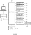
FIG. 23 is a block diagram of a control system of the nucleicacid inspection apparatus 110 according to the present embodiment. As shown inFIG. 23 , the control system of the nucleicacid inspection apparatus 110 is provided with acontroller 151, acommunicator 152, atray presence sensor 153, acard presence sensor 154, aframe fan 155, abuzzer 156, anLED 157, acurrent probe controller 158, amotor group 159, aphotosensor 160, atemperature sensor 161, atemperature adjuster 162, and apower supplier 163. - The
communicator 152 performs data communication between theinformation processing apparatus 150 and thecontroller 151. For example, thecommunicator 152 receives information set in theGUI windows information processing apparatus 150 from theinformation processing apparatus 150 and transfers the information to thecontroller 151. Moreover, thecommunicator 152 transfers a detection result of a current flowing to the electrode of theDNA chip 500 from thecontroller 151 to theinformation processing apparatus 150 and transfers abnormality detected by thecontroller 151 from thecontroller 151 to theinformation processing apparatus 150. Although, as a communication interface of thecommunicator 152, for example, an USB can be used, the communication interface is not limited to any specific type. Thecommunicator 152 is not always required to be wired, but may perform data communication wirelessly. - The
tray presence sensor 153 detects opening/closing of thetrays controller 151. Thetray presence sensor 153 detects opening/closing of thetrays - The
card presence sensor 154 detects whether the nucleicacid inspection card 700 is placed in thetrays controller 151. The detection of whether the nucleicacid inspection card 700 is placed in thetrays acid inspection card 700. - As shown in
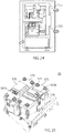
FIG. 24 , for example, there are twoframe fans 155 provided in the upward and downward directions on the rear side of the frame disposed in the vertical (upward and downward) direction from the installation surface. On the front side of the frame, an air flow inlet is provided. The rotation/stop of theframes fan 155 is controlled by thecontroller 151. When thecontroller 151 rotates theframe fans 155, the external air is taken in from the air flow inlet and circulated in the frame, and then taken out from theframe fans 155. In this way, the inside of the frame is cooled entirely. The number of theframe fans 155 and the installation location may be arbitrary changed depending on the frame size, shape, etc. - The
buzzer 156 and theLED 157 are, for example, turned on when there is an abnormality in the nucleicacid inspection apparatus 110. Depending on the type of abnormality, the sound state of thebuzzer 156 and the on-off state of theLED 157 may be changed. The on/off of thebuzzer 156 and theLED 157 is performed by thecontroller 151. - The
current probe controller 158 detects currents flowing into thecurrent probes 186 that are made in contact with the electrodes of theDNA chip 500. Since the current flowing into eachcurrent probe 186 is small, thecurrent probe controller 158 perform a process of removing a noise from the current flowing into eachcurrent probe 186, amplifying the current, and converting the amplified current into a voltage. - The
motor group 159 has fivemotors axis motor 184 controls the drive ofsyringe rods axis motor 181 controls the drive of theNOV rod 24 that performs opening/closing of the NO valves 710a1 and 710a2. The NCV-axis motor 185 controls the drive of theNC rod 20 that performs opening/closing of the NO valves 710v1, 710v2, 710v3, and 710V4. The heater-Peltier-axis motor 183 controls the drive of atemperature adjustment supporter 25 on which aheater 170 and a Peltier device171 are mounted. The probe-axis motor 182 controls the drive of aprobe holder 26 to which thecurrent probe 186 is attached. - In the vicinity of the above-mentioned five
motors photosensors 160 are provided respectively. The photosensor 160 associated with each motor optically detects the operation original position of each motor and returns each motor to the operation original positon. - As shown in
FIG. 25 , based on a temperature detection result oftemperature sensors heater 170 and aPeltier device 171, thetemperature adjuster 162 separately controls the temperature of theheater 170 and thePeltier device 171. Apart from thetemperature sensors temperature sensor 161c for measuring the temperature in the frame is also provided. Based on the temperature inside the frame, thetemperature adjuster 162 instructs the strength and on/off of theframe fans 155 to thecontroller 151. - The
power supplier 163 generates a plurality of direct-current power supply voltages to be used in respective parts in the nucleic currentacid inspection apparatus 110 and supplies the direct-current power supply voltages to the respective parts. Thepower supplier 163 has an AC/DC converter that generates a plurality of power supply voltages from a commercial power supply. -
FIG. 26 is a plan view that shows the installation locations of the fivemotors syringe rod 20, theNCV rod 23, theNOV rod 24, thetemperature adjustment supporter 25, and theprobe holder 26, driven by the motors.FIG. 26 is a plan view viewed from the side face of the nucleicacid inspection apparatus 110, the shown right side and left side being a front face and rear face, respectively. As shown inFIG. 26 , by a support plate 180 extending in the vertical (upward and downward) direction, the NOV-axis motor 181, the probe-axis motor 182, and the heater-Peltier-axis motor 183 are supported in order from above to below. Moreover, upwardly in the front side, asupport plate 191 that supports the syringe-axis motor 184 is disposed in the vertical direction. Furthermore, downwardly in the front side, a support plate 192 that supports the NCV-axis motor 185 is disposed in the vertical direction. The rotation axes of these five motors are each arranged in the lateral direction. With agear 14c of each rotation axis, arack gear 14d as shown inFIG. 27 is engaged to convert the rotation of arotation axis 12c into linear motion in the vertical direction, so that a rod associated with each motor moves in the vertical direction. Moreover, by switching the rotation direction of the rotation axis of each motor, the associated rod moves upward or downward. -
FIG. 28 is a plan view showing thesyringe rod 20 driven by the syringe-axis motor 184. Thesyringe rod 20 has fourfirst rods acid inspection card 700. The fourfirst rods first rod 201 is located in the lowest position, subsequently, the top potion of the second leftmostfirst rod 201 is lower, subsequently, the top potion of the rightmostfirst rod 204 is low, and the top potion of the second rightmostfirst rod 203 is the highest. The fourfirst rods common support plate 205. Thesupport plate 205 moves vertically in accordance with the rotation of the rotation axis of the syringe-axis motor 184. Therefore, the fourfirst rods - To the top potions of the four
first rods elastic punches -
FIG. 29 is a perspective vies of thepunch 213. Thepunch 213 has a slender shape so as to match the shape of each syringe. Thepunch 213 pushes down, from above, the dome-like packing 720 that constitutes the syringes 710C1, 710C2, 710C3, and 710C4, to push out the liquid in each syringe toward the associated flow passage. - In order to decide the punch shape, the inventor prepared two types of punches having different widths and studied whether there is a liquid remnant in a syringe when the syringe is pushed with the punches.
FIG. 30A shows an example of pushing the syringe 710c3 with awide punch 213a andFIG. 30B shows an example of pushing the syringe 710c3 with anarrow punch 213b.FIG. 31 shows the liquid amount in the syringe 710c3 in the case ofFIG.30A when the position at which thepunch 213b pushes the syringe 710c3 is shifted, when thepunch 213a is pushed to the syringe 710c3, the packing 720 of the syringe 710c3 is deformed into an M-shape as shown, so that a large slip load is generated between the packings, which causes the liquid remnant in the syringe. On the contrary, it is found that, in the case ofFIG. 30B , since the contact area between thepunch 213b and the syringe 710c3 is small, stress is concentrated on the center portion of the syringe 710c3, so that there is no liquid remnant in the syringe 710c3. In more specifically, it is found that it is desirable to make smaller the width of the punch in the lateral direction than the width of the syringe 710c3 in the lateral direction by 0. 3 mm or more. - Moreover, as shown in
FIG. 31 , when a location of thesyringe 710C shifted from the center is pushed with thesyringe rod 251, since thesyringe 710C cannot be pushed sufficiently, an enough liquid transfer amount cannot be obtained. Accordingly, as shown inFIG. 32 , the upper portion of the top portion of thesyringe rod 251 that moves vertically along arod guide 252, the upper portion being not contact with the nucleicacid inspection card 500, may be formed into ataper configuration 253, so that positioning with respect to the nucleicacid inspection card 700 can be made. According to this configuration, since the decrease in liquid transfer amount due to shift of the location where thesyringe rod 251 pushes thesyringe 710C can be avoided, an appropriate liquid transfer amount can be achieved. - The four
first syringe rods punches FIG. 28 , have different heights at their top portions. When the support plate goes down, thepunch 211 of the first rod having the lowest top portion is pushed to the upper surface of the firstly associated syringe (710C1), so that thefirst rod 201 is contacted. The lower thesupport plate 205 goes down, the stronger thepunch 211 pushes the syringe 710C1, so that the liquid in the syringe 710C1 is completely pushed out to the associated flow passage. - Since the heights of the top portions of the four
first rods first rod 201 is contact with the syringe 710C1, subsequently, the second leftmostfirst rod 202 is contact with the syringe 710C2, subsequently, the rightmostfirst rod 204 is contact with the syringe 710C4, and finally, the second rightmostfirst rod 203 is contact with the syringe 710C3. In order of contact with the upper surfaces of the syringes by the punch, the liquids in the syringes are pushed out from the syringes to the associated flow passages. - As described above, in the nucleic
acid inspection card 700 of the present embodiment, it is required to move the specimen sample, the first cleaning solution, the second cleaning solution, and the intercalating agent in this order, from the syringes 710C1, 710C2, 710C3, and 710C4 to the associated flow passages, respectively. Therefore, inFIG. 28 , in accordance with the order of sending the liquids from the syringes 710C1, 710C2, 710C3, and 710C4 to the associated flow passages, respectively, the heights of the top portions of the four first rods are different from one another. Therefore, by moving the support plate from above to below just once, the liquids in the syringes 710C1, 710C2, 710C3, and 710C4 can be moved to the respective flow passages in a predetermined order, so that syringe rod drive control is made easy. -
FIG. 33 is a plan view showing theNCV rod 23 driven by the NCV-axis motor 184. TheNCV rod 23 has foursecond rods acid inspection card 700. The four second rods extend from below to above in the frame, having thefork portions second rods fork portions - The tips of the
fork portions FIGS. 34(a) or 34(b) , or a tapered shape (C-surface shape) such as shown inFIG. 34C . Having such a tip shape, even if their positions are shifted a little bit with respect to the positions of the respective NC valves in the nucleicacid inspection card 700, each NC valve can be opened/closed. - NC valves 710v1, 710v2, 710v3, and 710V4 have, as explained with reference to
FIG. 11 , the configuration of a cantilever. The top portion of the cantilever is energized in the direction of closing the flow passage. Thefork portions - The four
second rods common support plate 230. Thesupport plate 230 moves vertically in accordance with the rotation of the NCV-axis motor 184. Therefore, the foursecond rods second rods fork portions - The four
second rods second rods FIG. 33 . - When the NCV-
axis motor 184 rotates to move thesupport plate 230 upward, firstly, the leftmostsecond rod 221 opens the associated NC valve 710v1, so that the specimen sample flows into theamplification flow passage 710f. When thesupport plate 230 goes up further, the second leftmostsecond rod 222 opens the associated NC valve 710v2, so that the first cleaning solution flows into the amplification flow passage710f. Moreover, when thesupport plate 230 goes up further, the rightmostsecond rod 224 opens the associated NC valve 710V4, so that the second cleaning solution passes through the flow passage and flows into theinspection flow passage 712 on theDNA chip 500. When thesupport plate 230 goes up further, the second rightmostsecond rod 223 opens the associated NC valve 710v3, so that the intercalating agent passes through the flow passage and flows into theinspection flow passage 712 on theDNA chip 500. - As described above, the four
second rods common support plate 230. Therefore, by just one vertical movement of thesupport plate 230, the four the NC valves 710v1, 710v2, 710v3, and 710V4 can be opened in order, so that the liquids in the four syringes 710c1, 710c2, 710c3, and 710c4 can be moved to the associated flow passages in order. Accordingly, the opening/closing control of the NC valves 710v1, 710v2, 710v3, and 710V4 can be performed easily. -
FIG. 35 is a plan view showing theNOV rod 24 driven by the NOV-axis motor 181. TheNOV rod 24 has twothird rods acid inspection card 700, and athird positioning rod 242. The threethird rods third positioning rod 242 has a top portion little bit higher than the top portions of the remaining tworods - These
third rods common support plate 240. Thesupport plate 240 moves vertically in accordance with the rotation of the NOV-axis motor 181. Therefore, the threethird rods - When the
support plate 240 moves downward, Among the three, the centerthird rod 242 is firstly made contact with the upper surface of the nucleicacid inspection card 700 to perform positioning. The remaining twothird rods FIG. 6 , to close the flow passages. - As shown in
FIG. 35 , although the top portion of thethird positioning rod 242 is higher than the remaining tworods rods acid inspection card 700, before the twothird rods third positioning rod 242 is made in contact with the upper surface of the nucleicacid inspection card 700 to perform positioning. - As explained with reference to
FIG. 9 , the two NO valves 710a1 and 710a2 are provided at the outlet and inlet of theamplification flow passage 710f on the nucleicacid inspection card 700. By closing the NO valves 710a1 and 710a2 with thethird rods amplification flow passage 710f can be prevented from reverse flow to the syringes or flow to theDNA chip 500. In the present embodiment, while the NO valves 710a1 and 710a2 are being closed, theamplification flow passage 710f is heated to perform nucleic acid amplification. -
FIG. 36A is a plan view of thetemperature adjustment supporter 25 driven by the heater-Peltier-axis motor 183.FIG. 36B is a perspective view of thetemperature adjustment supporter 25. Thetemperature adjustment supporter 25 has afirst support plate 174 for supporting theheater 170, asecond support plate 175 for supporting thePeltier device 171, and an elastic member such as a spring disposed between the first andsecond support plates third support plate 176. While the elastic member is not being energized, thefirst support plate 174 and thesecond support plate 175 are located at an almost same height. Thethird support plate 176 moves vertically by therotation 183 of the heater-Peltier-axis motor and, and thus thefirst support plate 174 and thesecond support plate 175 synchronically move vertically. - The
heater 170 disposed on the upper surface of thefirst support plate 174 has a rectangular shape. ThePeltier device 171 disposed on the upper surface of thesecond support plate 175 also has a rectangular shape. When thethird support plate 176 moves upward, theheater 170 is stored in one of the concave portions provided on the rear face side of the nucleicacid inspection card 700 and thePeltier device 171 is stored in the other concave portion. The concave portions provided on the rear face side of the nucleicacid inspection card 700 have a size that matches the external shape of theheater 170 and thePeltier device 171. By storing theheater 170 and thePeltier device 171 in these concave portions, precise positioning of theheater 170 and thePeltier device 171 is performed. The concave portion for the heater in the nucleicacid inspection card 700 is provided just under theamplification flow passage 710f. The concave portion for the Peltier device is provided just under theinspection flow passage 712 on theDNA chip 500. With this arrangement, theheater 170 can heat theamplification flow passage 710f and thePeltier device 171 can heat and cool theinspection flow passage 712. - As described above, although the
heater 170 and thePeltier device 171 are made in contact with the nucleicacid inspection card 700 almost at the same time, the heat control of theheater 170 and the temperature adjustment control of thePeltier device 171 can be done separately. In the present embodiment, before starting nucleic acid amplification at the nucleicacid inspection card 700, thetemperature adjustment supporter 25 goes up to make theheater 170 and thePeltier device 171 in contact with the nucleicacid inspection card 700 and, thereafter, the specimen sample in the syringe is moved to theamplification flow passage 710f to be subject to nucleic acid amplification while being heated by the heater. Thereafter, when the nucleic-acid amplified specimen sample moves to theinspection flow passage 712 on theDNA chip 500, the Peltier device heats and cools theinspection flow passage 712. Thetemperature adjustment supporter 25 is held upward until the probe is made contact with theDNA chip 500 to perform current detection. -
FIG. 37A is a plan view of theprobe holder 26 driven by the probe-axis motor 182.FIG. 37B is a perspective view of theprobe holder 26. Theprobe holder 26 is disposed above the nucleicacid inspection card 700. Theprobe holder 26 has asupport plate 197 for supporting thecurrent probe 186. Thesupport plate 197 moves vertically in accordance with the rotation of the probe-axis motor 182. On the rear face side of thesupport plate 197, thecurrent probe 186, and pins 261 and 262 for positioning thecurrent probe 186 are provided. Thecurrent probe 186 has, as shown inFIG. 38 , a built-inspring 263. When the pressure to push down thepins spring 263, the pressure to push down the probe pins 261 and 262 becomes a push-down stress so as to have conductivity to the nucleicacid inspection card 700. Although the present embodiment has the configuration with the built-inspring 263, an elastic body other than thespring 263 can be adopted. - There are
current probes 186 for the number of the electrodes on theDNA chip 500. On thesupport plate 197, a wiring pattern for detecting a current flowing through eachcurrent probe 186 is formed. When the probe-axis motor 182 is driven, thecurrent probe 186 gradually moves downward and, firstly, the positioning pins 261 and 262 are engaged with hole portions on the nucleicacid inspection card 700 for positioning, thereafter, thecurrent probe 186 is made contact with each electrode on theDNA chip 500. Since the positioning pins 261 and 262 perform positioning firstly, manycurrent probes 186 are made in contact with the associated electrodes on theDNA chip 500 accurately. -
FIG. 39 is a flowchart showing an example of a drive sequence of each motor by thecontroller 151.FIG. 40 is a diagram showing a move state of a liquid on the nucleicacid inspection card 700. Hereinbelow, based on the drawings, the process of nucleic acid inspection will be explained. - The probe-
axis motor 182 is driven to move down theprobe holder 26. While thecurrent probe 186 is being positioned, thecurrent probe 186 is made contact with each electrode on theDNA chip 500 attached to the nucleic acid inspection card 700 (step S1). - The NOV-
axis motor 181 is driven to make thethird rod 242 for positioning theNOV rod 24 contact with the predetermined position of the nucleicacid inspection card 700 to perform positioning (step S2). - The heater-Peltier-
axis motor 183 is driven to move up thetemperature adjustment supporter 25 to store theheater 170 and thePeltier device 171 in the concave portions at the rear face side of the nucleicacid inspection card 700 to perform positioning (step S3). In this state, since the NC valves 710v1, 710v2, 710v3, and 710V4 are all closed, as shown inFIG. 40A , the liquids in the four syringes 710C1, 710C2, 710C3, and 710C4 do not flow into the flow passages. - The NC valve-
axis motor 185 is driven to move up theNCV rod 23 to make the top portion of thesecond rod 221, the top portion of which has been located highest, raise the associated cantilever to open the NC valve 710v1 located at the outlet of the syringe for the specimen sample (step S4). - The syringe-axis motor 187 is driven to move down the
syringe rod 20 to push thefirst rod 201, the top portion of which has been located lowest, to the upper surface of the syringe 710C1 for the specimen sample to push out the specimen sample to the flow passage (step S5). In this way, as shown inFIG. 40B , the specimen sample in the syringe 710C1 for the specimen sample passes through the flow passage and flows into theamplification flow passage 710f. - The NOV-
axis motor 181 is driven to make the twothird rods NOV rod 24 contact with the packing 720 of the NO valve to close the NO valves 710a1 and 710a2, and theheater 170 heats theamplification flow passage 710f (step S6). By the heating, amplification of nucleic acid contained in the specimen sample is performed in theamplification flow passage 710f. When the amplification of nucleic acid is complete, theheater 170 stops heating. Since theheater 170 has no particular cooling function, natural cooling is performed. - The NOV-
axis motor 181 is driven in the reverse direction of that in step S6 to open the NO valves 710a1 and 710a2 (step S7). - The NC valve-
axis motor 185 is driven in the same direction as that in step S4, to move up further theNCV rod 23 to make the top portion of thesecond rod 222, the top portion of which has been located at the second highest position, to raise the associated cantilever to open the NC valve 710v2 located at the outlet of the syringe 710C2 for the first cleaning solution (step S8). - The syringe-axis motor 187 is driven in the same direction as that in step S5, to move down further the
syringe rod 20 to push thefirst rod 202, the top portion of which has been located at the second lowest position, to the upper surface of the syringe 710C2 for the first cleaning solution, to push out the first cleaning solution to theamplification flow passage 710f (step S9). In this way, as shown inFIG. 40C , the first cleaning solution enters theamplification flow passage 710f and the nucleic-acid amplified specimen sample in theamplification flow passage 710f is pushed out to the detection flow passage in theDNA chip 500. - Like step S6, the NOV-
axis motor 181 is driven to make the twothird rods NOV rod 24 contact again with the packing 720 of the NO valve to close the NO valves 710a1 and 710a2. In parallel with this, thePeltier device 171 heats the DNA chip 500 (step S10). - Subsequently, the NC valve-
axis motor 185 is driven in the same direction as that in steps S4 and S8 to move up further theNCV rod 23 to make the top portion of thesecond rod 224, the top portion of which has been located at the third highest position, to raise the associated cantilever to open the NC valve 710v4 located at the outlet of the syringe 710C4 for the second cleaning solution (step S11). - Subsequently, the syringe-
axis motor 184 is driven in the same direction as that in steps S5 and S9 to move down further thesyringe rod 20 to push thefirst rod 204, the top portion of which has been located at the third lowest position, to the upper surface of the syringe 710C4 for the second cleaning solution, to push out the second cleaning solution to the flow passage connected to the DNA chip 500 (step S12). In this way, as shown inFIG. 40D , the second cleaning solution moves to theinspection flow passage 712 on theDNA chip 500 and specimen sample accumulated so far in theinspection flow passage 712 is pushed out to the waste liquid tanks 711g1 and 711g2. - Subsequently, the NC valve-
axis motor 185 is driven in the same direction as that in steps S4, S8, and S11 to move up further the second rod to make the top portion of thesecond rod 223, the top portion thereof has been located at the lowest position, raise the associated cantilever to open the NC valve 710v3 located at the outlet of the syringe 710C3 for the intercalating agent (step S13). - Subsequently, the syringe-axis motor 187 is driven in the same direction as that in steps S5, S9, and S12 to move down further the
syringe rod 20 to push thefirst rod 203, the top portion thereof has been located at the highest position, to the upper surface of the syringe 710C3 for the intercalating agent, to push out the intercalating agent to the flow passage connected to the DNA chip 500 (step S14). In this way, as shown inFIG. 40E , the intercalating agent moves to theinspection flow passage 712 on theDNA chip 500 and the second cleaning solution accumulated so far in theinspection flow passage 712 is pushed out to the waste liquid tank. Thereafter, thecurrent probe 186 having contact with the electrode of theDNA chip 500 detects a current flowing into the electrode. -
FIG. 41 is a block diagram of a control system of the nucleicacid inspection apparatus 110. As shown inFIG. 41 , inside the nucleicacid inspection apparatus 110, acontrol substrate 121, acommunication interface substrate 122, aprobe substrate 123, aphotosensor substrate 124, atemperature adjusting substrate 125, and apower substrate 127 are provided. It is not always required to divide into these substrates. For example, a plurality of substrates may be united into one substrate. - On the
control substrate 121, acontroller 151 and acurrent detector 128 are mounted. On thecommunication interface substrate 122, acommunicator 152 having a USB (Universal Serial Bus) hub function is mounted. On theprobe substrate 123, a plurality ofcurrent probes 186, a wiring pattern for transferring a current flowing through thecurrent probe 186, and aprobe controller 151 for amplifying the current of thecurrent probe 186 to convert the amplified current into a voltage are provided. On thephotosensor substrate 124, aphotosensor 160 for detecting the operation original position of each of themotors 181 to 185 in the motor group (liquid transfer unit) 159 is mounted. On thetemperature adjusting substrate 125, the heater (heating unit) 170 and the Peltier device (temperature adjuster) 171, the temperature sensor (temperature measuring unit) 161a for theheater 170, the temperature sensor (temperature measuring unit) 161b for thePeltier device 171, the temperature sensor (temperature measuring unit) 161c for measuring the temperature in the frame, and thetemperature adjuster 162 for performing temperature adjustment of theheater 170 and thePeltier device 171 are mounted. On thepower substrate 127, thepower supplier 163 for generating a plurality of direct-current power supply voltages from a commercial power supply and apower fan 129 are mounted. - The
controller 151 receives signals detected by thetray presence sensor 153, thecard presence sensor 154, thephotosensor 160, and thetemperature sensors controller 151 detects opening/closing of thetrays acid inspection apparatus 110, using thetray presence sensor 153. Detection of opening/closing of thetrays trays controller 151 detects whether the nucleicacid inspection card 700 is placed in thetrays card presence sensor 154. Thecontroller 151 detects the rotational positions of themotors 181 to 185 of themotor group 159, using thephotosensor 160. Moreover, thecontroller 151 detects the temperature inside the frame, the temperature of theheater 170, and the temperature of thePeltier device 171, using thetemperature sensors - The
controller 151 controls the frame fan (ventilator) 155, thebuzzer 156, the LED157, and themotor group 159. - As shown in
FIG. 24 , for example, there are twoframe fans 155 provided in the upward and downward directions on the rear face side of the frame disposed in the vertical (upward and downward) direction from the installation surface. Theframe fan 155 takes external air into the frame, circulates the taken external air inside the frame and takes out the air to the outside of the frame. On the front-face lower side of the frame, an air flow inlet is provided. The rotation/stop of theframes fan 155 is controlled by thecontroller 151. When thecontroller 151 rotates theframe fans 155, the external air is taken from the air flow inlet and circulated in the frame, and then taken out from theframe fans 155. In this way, the inside of the frame is cooled entirely. The number of theframe fans 155 and the installation location may be arbitrary changed depending on the frame size, shape, etc. - The
buzzer 156 and theLED 157 are, for example, turned on when there is an abnormality in the nucleicacid inspection apparatus 110. Depending on the type of abnormality, the sound state of thebuzzer 156 and the on-off state of theLED 157 may be changed. The on/off of thebuzzer 156 and theLED 157 is performed by thecontroller 151. - The
current probe controller 158 detects currents flowing into thecurrent probes 186 that are made in contact with the electrodes of theDNA chip 500. Since the current flowing into eachcurrent probe 186 is small, thecurrent probe controller 158 perform a process of removing a noise from the current flowing into eachcurrent probe 186, amplifying the current, and converting the amplified current into a voltage. - As shown in
FIG. 26 , themotor group 159 has fivemotors 181 to 185.FIG. 26 is a plan view that shows the installation locations of the fivemotors 181 to 185, thesyringe rod 20, theNCV rod 23, theNOV rod 24, thetemperature adjustment supporter 25, and theprobe holder 26, driven by these motors.FIG. 26 is a plan view viewed from the side face of the nucleicacid inspection apparatus 110, the shown right side and left side being a front face and rear face, respectively. - Among the five
motors 181 to 185, the syringe-axis motor 184 controls driving of thesyringe rods 201 to 204 each for moving the liquid in each syringe to the flow passage. The NOV-axis motor 181 controls driving of theNOV rod 24 for opening/closing the NO valves 710a1 and 710a2. The NCV-axis motor 185 controls driving of theNC rod 20 for opening/closing the NC valve (NVC). The heater-Peltier-axis motor 183 controls driving of thetemperature adjustment supporter 25 on which theheater 170 and thePeltier device 171 are mounted. The probe-axis motor 182 controls driving of theprobe holder 26 to which thecurrent probe 186 is attached. - As shown in
FIG. 26 , by a support plate 180 extending in the vertical (upward and downward) direction, the NOV-axis motor 181, the probe-axis motor 182, and the heater-Peltier-axis motor 183 are supported in order from above to below. Moreover, upwardly in the front side, thesupport plate 191 that supports the syringe-axis motor 184 is disposed in the vertical direction. Furthermore, downwardly in the front side, the support plate 192 that supports the NCV-axis motor 185 is disposed in the vertical direction. The rotation axes of these five motors are each arranged in the lateral direction. With a gear of each rotation axis, a rack gear is engaged to convert the rotation of arotation axis 12c into linear motion in the vertical direction, so that a rod associated with each of themotors 181 to 185 moves in the vertical direction. Moreover, by switching the rotation direction of the rotation axis of each of themotors 181 to 185, the associated rod moves upwardly or downwardly. - In the vicinity of the above-mentioned five
motors photosensors 160 are provided respectively. The photosensor 160 associated with each of themotors 181 to 185 optically detects the operation original positon of each of themotors 181 to 185 and returns each of themotors 181 to 185 to the operation original positon. - The
current detector 128 shown inFIG. 41 detects a current flowing to thecurrent probe 186. The current flowing to thecurrent probe 186 is converted into a voltage on theprobe substrate 123 and then sent to thecurrent detector 128. Thecurrent detector 128 detects a voltage in accordance with the current flowing to thecurrent probe 186 while offset correction and circuit noise removal are being performed. - As shown in
FIG. 25 , based on a temperature detection result of thetemperature sensors heater 170 and thePeltier device 171, thetemperature adjuster 162 separately controls the temperature of theheater 170 and thePeltier device 171. Apart from thetemperature sensors temperature sensor 161c for measuring the temperature in the frame is also provided. Based on the temperature inside the frame, thetemperature adjuster 162 instructs the strength and on/off of theframe fans 155 to thecontroller 151. - The
power supplier 163 generates a plurality of direct-current power supply voltages to be used in respective parts in the nucleic currentacid inspection apparatus 110 and supplies the direct-current power supply voltages to the respective parts. Thepower supplier 163 has an AC/DC converter that generates a plurality of power supply voltages from a commercial power supply. -
FIG. 42 is a functional block diagram related to self-diagnosis of theinformation processing apparatus 150 according to the present embodiment. Theinformation processing apparatus 150 ofFIG. 42 has first tosixth diagnosis units 131 to 136, awarning unit 137, adiagnosis window generator 138, and adiagnosis controller 139. The first tosixth diagnosis units 131 to 136 automatically perform self-diagnosis when the nucleicacid inspection apparatus 110 is turned on. The first tosixth diagnosis units 131 to 136 can perform self-diagnosis at any timing arbitrarily selected by thediagnosis window generator 138. - The
first diagnosis unit 131 performs communication confirmation with thecontroller 151 and thecurrent detector 128 in the nucleicacid inspection apparatus 110. In more specifically, thefirst diagnosis unit 131 transmits predetermined signals from theinformation processing apparatus 150 to thecontroller 151 and thecurrent detector 128, respectively, to perform communication confirmation by determining whether response signals to these signals have been returned from thecontroller 151 and thecurrent detector 128, respectively, within a predetermined period. As shown inFIG. 41 , theinformation processing apparatus 150 perform information transmission and reception with the nucleicacid inspection apparatus 110 via thecommunication interface substrate 122 in the nucleicacid inspection apparatus 110, for example, in accordance with USB standards. - The
second diagnosis unit 132 performs operation confirmation of a plurality of motors. Thesecond diagnosis unit 132 performs operation confirmation of themotors 181 to 185 using thephotosensor 160 provided at the operation original position of each of themotors 181 to 185. That is, by rotating each of themotors 181 to 185 in a normal direction from the operation original position and then in a reverse direction, it is determined with the photosensor 160 whether each of themotors 181 to 185 returns to the operation original position. If each motor returns to the operation original position, it is determined that the operation is normal. If each motor returns a position shifted from the operation original position, it is determined that the operation is abnormal. - The
third diagnosis unit 133 performs operation confirmation of theheater 170 and thePeltier device 171. In more specifically, thethird diagnosis unit 133 performs heating for a predetermined period with theheater 170 and thePeltier device 171 and measures the temperature increase with thetemperature sensors heater 170 and thePeltier device 171, respectively. Then, it is determined that the operation is normal if a temperature increase value per unit of time is within a predetermined range and determined that the operation is abnormal if the temperature increase value is out of the predetermined range. - The
fourth diagnosis unit 134 performs operation confirmation of the fans. Inside the nucleicacid inspection apparatus 110, theframe fan 155 and thepower fan 129 are provided. While theframe fan 155 and thepower fan 129 are rotating, thefourth diagnosis unit 134 detects signals output from theframe fan 155 and thepower fan 129. The signals output from theframe fan 155 and thepower fan 129 are signals that have a predetermined logic while theframe fan 155 and thepower fan 129 are rotating. Thefourth diagnosis unit 134 determines that the operation is normal if the above-mentioned signals have the predetermined logic and determines that the operation is abnormal if the above-mentioned signals have another logic. - The
fifth diagnosis unit 135 performs operation confirmation of thecurrent detector 128. Thecurrent detector 128 determines, after offset adjustments, whether a current flowing through the electrode on theinspection flow passage 712 becomes zero amperes in the state where the specimen sample is not injected intoinspection flow passage 712 of theDNA chip 500 attached to the nucleicacid inspection card 700. - The
sixth diagnosis unit 136 determines whether the temperature in the frame of the nucleicacid inspection apparatus 110 is within a predetermined temperature range. Thesixth diagnosis unit 136 acquires a temperature measured by thetemperature sensor 161c provided in a specific location in the frame (for example, on a relay substrate 126) to determine that the temperature is normal if the temperature is within the predetermined temperature range and abnormal if the temperature is out of the predetermined temperature range. - The
warning unit 137 performs a warning process if at least one of the first tosixth diagnosis units 131 to 136 determines abnormal. The warning process is, for example, to display an abnormal location on the display screen of theinformation processing apparatus 150. In this occasion, in order to get operator' attention, the abnormal location may be displayed with a striking color or with flashing. Or the warning process may give off a warning sound in at least either one of the nucleicacid inspection apparatus 110 and theinformation processing apparatus 150. The actual contents of the warning process performed by thewarning unit 137 may be arbitrarily changed. For example, if abnormality does not affect nucleic acid inspection, the nucleic acid inspection may be continuously performed and if the abnormality affects the nucleic acid inspection, the abnormal location may be noticed to urge a user to inspect and repair and forcibly shut down the nucleicacid inspection apparatus 110, so as not to perform unreliable nucleic acid inspection. - The
diagnosis controller 139 instructs the above-described first tosixth diagnosis units 131 to 136 to perform self-diagnosis when the nucleicacid inspection system 100 is turned on. There is no particular order of diagnosis performed by the first tosixth diagnosis units 131 to 136. Depending on the situation, at least part of the self-diagnosis by the first tosixth diagnosis units 131 to 136 may be performed in parallel. - Moreover, the
diagnosis controller 139 may let a user select a diagnosis unit among the first tosixth diagnosis units 131 to 136 and make the user-selected diagnosis unit perform self-diagnosis at an arbitrary timing. - The
diagnosis window generator 138 generates a diagnosis window to be displayed on the display screen of theinformation processing apparatus 150. On the diagnosis window, results of self-diagnosis by the first tosixth diagnosis units 131 to 136 automatically performed at power-on are displayed. Moreover, on the diagnosis window, buttons with which a user arbitrarily selects a self-diagnosis item, a button for starting self-diagnosis, etc. are provided. -
FIG. 43 is an illustration showing an example of a display screen of a self-diagnosis result. As shown inFIG. 43 . The self-diagnosis result is displayed for each of the fourinspection units 1 to 4 provided to the nucleicacid inspection apparatus 110.FIG. 43 shows an example of the display screen to display abnormal contents, in theinspection unit 1, which are abnormality in which wire disconnection is detected in thePeltier device 171 and abnormality in which the fan for thePeltier device 171 remains stopped. The display format to display abnormal contents is not limited to that shown inFIG. 43 . -
FIG. 44 is a display example of a diagnosis window on which a user arbitrarily selects a self-diagnosis item. On the display screen ofFIG. 44 , a check button group B1 for selecting detection of thecard 700, detection of thetrays 111 to 114, detection of rotation of the upper frame fan 155 (case fan 1), detection of rotation of the lower frame fan 155 (case fan 2), and detection of rotation of thepower fan 129, a check button group B2 for selecting detailed items related to operation confirmation of thePeltier device 171, and a check button group B3 for selecting detailed items related to operation confirmation of theheater 170.FIG. 44 is an example of the diagnosis window which may be arbitrarily changed. -
FIG. 45 is a flowchart showing an example of a self-diagnosis process to be automatically performed by theinformation processing apparatus 150 when turned on. Firstly, theinformation processing apparatus 150 performs self-diagnosis with the first diagnosis unit 131 (step S1). In more specifically, thediagnosis controller 139 in theinformation processing apparatus 150 performs communication confirmation with thecontroller 151 and thecurrent detector 128 in the nucleicacid inspection apparatus 110. As described above, thecontroller 151 and thecurrent detector 128 are both mounted on thecontrol substrate 121. In step S1, theinformation processing apparatus 150 transmits a communication signal to the nucleicacid inspection apparatus 110 via thecommunication interface substrate 122. If a response signal to the communication signal is received by theinformation processing apparatus 150 via thecommunication interface substrate 122 within a predetermined period, it is determined that communication is confirmed to be normal (YES in step S2). - The
information processing apparatus 150 also receives diagnosis results of thesecond diagnosis unit 132 to thesixth diagnosis unit 136 via thecommunication interface substrate 122. Therefore, if abnormality is determined by the first diagnosis unit 131 (NO in step S2), the warning process is performed without diagnosis by thesecond diagnosis unit 132 to the sixth diagnosis unit 136 (step S3). - If a diagnosis result of the
first diagnosis unit 131 shows normality, thesecond diagnosis unit 132 performs self-diagnosis (step S4). In more specifically, thesecond diagnosis unit 132 performs operation confirmation of a plurality of motors. Here, as described above, a motor is rotated in a normal direction from the operation original position and then in a reverse direction, it is then determined whether the motor returns to the operation original position. If there is a motor determined as abnormal in step S4 (NO in step S5), information on the motor is transferred to theinformation processing apparatus 150 via the communication interface substrate 122 (step S6). - If a diagnosis result of the
second diagnosis unit 132 shows normality (YES in step S5), thethird diagnosis unit 133 performs self-diagnosis (step S7). In more specifically, thethird diagnosis unit 133 performs operation confirmation of theheater 170 and thePeltier device 171. If at least either one of theheater 170 and thePeltier device 171 is determined as abnormal (NO in step S8), its information is transferred to theinformation processing apparatus 150 via the communication interface substrate 122 (step S9). - If a diagnosis result of the
third diagnosis unit 133 shows normality (YES in step S8), thefourth diagnosis unit 134 performs self-diagnosis (step S10). In more specifically, thefourth diagnosis unit 134 performs operation confirmation of a fan. If it is determined as abnormal such that the fan does not rotate (NO in step S11), its information is transferred to theinformation processing apparatus 150 via the communication interface substrate 122 (step S12). - If a diagnosis result of the
fourth diagnosis unit 134 shows normality (YES in step S11), thefifth diagnosis unit 135 performs self-diagnosis (step S13). In more specifically, thefifth diagnosis unit 134 performs operation confirmation of thecurrent detector 128. After offset adjustments, and in the state where the specimen sample is not injected into the inspection flow passage of the DNA chip attached to the nucleic acid inspection card, if abnormality is determined such that a current flowing through the electrode on theinspection flow passage 712 does not become zero amperes (NO in step S14), its information is transferred to theinformation processing apparatus 150 via the communication interface substrate 122 (step S15). - If a diagnosis result of the
fifth diagnosis unit 135 shows normality (YES in step S14), thesixth diagnosis unit 136 performs self-diagnosis (step S16). In more specifically, if the temperature in the frame of the nucleicacid inspection apparatus 110 is within a predetermined temperature range, normality is determined and, if out of the predetermined temperature range, abnormality is determined (step S17). If abnormality is determined, its information is transferred to theinformation processing apparatus 150 via the communication interface substrate 122 (step S17). - When receiving abnormality information in at least one of the steps S3, S6, S9, S12, S15, and S18 in
FIG. 45 , theinformation processing apparatus 150 performs the warning process such as displaying the abnormality information on the display screen, or the like. - As described above, in the nucleic
acid inspection apparatus 110 according to the present embodiment, what a user is to do is just placing the nucleicacid inspection card 700 capable of performing nucleic acid amplification and nucleic acid inspection in a tray of the nucleicacid inspection apparatus 110, thereafter, the nucleicacid inspection apparatus 110 automatically performs nucleic acid amplification and nucleic acid inspection. Therefore, in addition to that labor of nucleic acid inspection can be omitted to improve convenience, time to obtain a nucleic acid inspection result can be drastically shortened. - Moreover, since all of the specimen sample and necessary reagents and the like can be stored in one nucleic
acid inspection card 700 and nucleic acid amplification and nucleic acid inspection can be done within this card, the amount of reagents to be used can be reduced and a material cost for nucleic acid inspection can be drastically reduced. - In order to perform higher accurate positioning, as pre-steps of "move down the
current probe 186" in S1 ofFIG. 31 , the flowing steps may be added. - (1) Firstly, in order to perform rough positioning of the nucleic
acid inspection card 700 and theprobe holder 26, the probe-axis motor 182 is driven to move down theprobe holder 26 to insert the positioning pins 261 and 262 into positioning holes of the nucleicacid inspection card 700, as shown inFIG. 30 . Then, theprobe holder 26 is stopped before thecurrent probe 186 is made contact with the associated electrode. - (2) Subsequently, in order to perform further positioning, the NC valve-
axis motor 185 is driven to move up theNCV rod 23 and, before the top portion of thesecond rod 221, the top portion of which has been located at the highest position, is made contact with the associated cantilever, the NC valve-axis motor 185 is stopped. - By adding the above pre-steps, higher accurate positioning can be achieved.
- The nucleic
acid inspection apparatus 110 has necessary motors and the like installed compactly in a small-space frame such as shown inFIG. 18 and, as shown inFIG. 45 , heat release is considered, so that compactness can be achieved and power consumption can be restricted. - Moreover, the
information processing apparatus 150 according to the present embodiment automatically performs self-diagnosis with the first tosixth diagnosis units 131 to 136 when the nucleicacid inspection apparatus 110 is turned on. Therefore, any abnormality that occurs in the nucleicacid inspection apparatus 110 can be quickly detected, so that nucleic acid inspection in an abnormal state can be avoided. Moreover, if abnormality is determined, abnormal contents can be displayed on a display screen of theinformation processing apparatus 150, so that an abnormal location can be quickly identified. Depending on the situations, thebuzzer 156 and theLED 157 of the nucleicacid inspection apparatus 110 can be used to notice a user of occurrence of abnormality. - Furthermore, in the present embodiment, among a plurality of self-diagnosis functions, any self-diagnosis function can be selected by a user on the display screen of the
information processing apparatus 150 to be performed at any timing. Therefore, nucleic acid inspection can be performed in the most appropriate state of the nucleicacid inspection apparatus 110. Especially, in the present embodiment, on the GUI window displayed on the display screen of theinformation processing apparatus 150, any self-diagnosis item can be selected, so that selection of the self-diagnosis item is made easy to improve user convenience. - At least part of the nucleic
acid inspection apparatus 110 explained in the embodiment may be configured with hardware or software. When it is configured with software, a program that performs at least part of the functions of the nucleicacid inspection apparatus 110 may be stored in a storage medium such as a flexible disk and CD-ROM, and then installed in a computer to run thereon. The storage medium may not be limited to a detachable one such as a magnetic disk and an optical disk but may be a standalone type such as a hard disk and a memory. - Moreover, a program that achieves at least part of the functions of the nucleic
acid inspection apparatus 110 may be distributed via a communication network a (including wireless communication) such as the Internet. The program may also be distributed via an online network such as the Internet or a wireless network, or stored in a storage medium and distributed under the condition that the program is encrypted, modulated or compressed. - While certain embodiments have been described, these embodiments have been presented by way of example only, and are not intended to limit the scope of the inventions. Indeed, the novel methods and systems described herein may be embodied in a variety of other forms; furthermore, various omissions, substitutions and changes in the form of the methods and systems described herein may be made without departing from the spirit of the inventions. The accompanying claims and their equivalents are intended to cover such forms or modifications as would fall within the scope and spirit of the inventions.
Claims (20)
- A nucleic acid inspection apparatus comprising:an installer to install a nucleic acid inspection device, the installer comprising a storage unit to store at least a specimen sample, an amplifier to amplify nucleic acid contained in the specimen sample stored in the storage unit, a first flow passage to move the specimen sample from the storage unit to the amplifier, an inspection unit to inspect the nucleic acid contained in the specimen sample nucleic-acid amplified by the amplifier, and a second flow passage to move the specimen sample from the amplifier to the inspection unit;a first opening/closing unit to open/close the first flow passage;a second opening/closing unit to open/close the second flow passage;a heater to heat the amplifier; anda controller to control the first and second opening/closing units so as to open/close in a predetermined order and to control the heater so as to heat the amplifier in conjunction with opening/closing operations of the first and second opening/closing units.
- The nucleic acid inspection apparatus of claim 1 further comprising a third opening/closing provided in the first flow passage, the third opening/closing unit controlling flow of the specimen sample into the amplifier,
wherein the first opening/closing unit is provided in the first flow passage, the first opening/closing unit controlling flow of the specimen sample from the storage unit,
the second opening/closing unit is provided in the second flow passage, the second opening/closing unit controlling flow of the specimen sample to the inspection unit, and
the controller opens the first opening/closing unit to move the specimen sample stored in the storage unit to the amplifier and then closes the second and third opening/closing units to heat the amplifier, at the heater. - The nucleic acid inspection apparatus of claim 2, wherein the storage unit further stores a first cleaning solution,
wherein the nucleic acid inspection device comprises a third flow passage branching off from the first flow passage, the third flow passage moving the first cleaning solution from the storage unit to the amplifier, and
the nucleic acid inspection apparatus further comprising:a fourth opening/closing unit to open/close the third flow passage; anda heater/cooler for temperature adjustment of the inspection unit,wherein the controller, after completion of nucleic acid amplification by the amplifier, opens the second to fourth opening/closing units to move the first cleaning solution to the amplifier via the third and first flow passages and closes the second opening/closing unit to perform temperature adjustment of the inspection unit, at the heater/cooler. - The nucleic acid inspection apparatus of claim 3, wherein the storage unit further stores a second cleaning solution,
wherein the nucleic acid inspection device comprises a fourth flow passage branching off from the second flow passage, the fourth flow passage moving the second cleaning solution from the storage unit to the inspection unit, and
the nucleic acid inspection apparatus further comprising a fifth opening/closing unit to open/close the fourth flow passage; and
wherein the controller opens the fifth opening/closing unit to move the second cleaning solution to the inspection unit via the fourth and second flow passages. - The nucleic acid inspection apparatus of claim 4, wherein the storage unit further stores a reagent to be used for nucleic acid inspection,
wherein the nucleic acid inspection device comprises a fifth flow passage branching off from the second flow passage, the fifth flow passage moving the reagent from the storage unit to the inspection unit, and
the nucleic acid inspection apparatus further comprising a sixth opening/closing unit to open/close the fifth flow passage; and
wherein the controller opens the sixth opening/closing unit to move the reagent to the inspection unit via the fifth and second flow passages to inspect the nucleic acid contained in the specimen sample, at the inspection unit. - The nucleic acid inspection apparatus of claim 5, wherein the nucleic acid inspection device comprises a plurality of electrodes, a plurality of molecules to cause hybridization between different kinds of nucleic acid being attached to the plurality of electrodes,
wherein the inspection unit determines whether an oxidation current flows to the plurality of electrodes due to hybridization when the reagent is moved to the inspection unit, to inspect nucleic acid contained in the specimen sample. - The nucleic acid inspection apparatus of claim 5, wherein the storage unit comprises a first storage chamber to store the specimen sample, a second storage chamber to store the first cleaning solution, a third storage chamber to store the second cleaning solution, and a third storage chamber to store the reagent,
the nucleic acid inspection apparatus further comprising four first rods to give pressure to the first to fourth storage chambers to push stored objects to associated flow passages,
wherein the controller moves the four first rods in one direction in synchronism one another, and
while the four first rods are moving in the one direction, one of the four first rods firstly gives pressure to the first storage chamber to push the specimen sample to the first flow passage, subsequently, another one of the four first rods gives pressure to the second storage chamber to push the first cleaning solution to the third flow passage, subsequently, a still another one of the four first rods gives pressure to the third storage chamber to push the second cleaning solution to the fourth flow passage, and subsequently, a further another one of the four first rods gives pressure to the fourth storage chamber to push the reagent to the fifth flow passage. - A base sequence detection chip comprising:a plurality of first electrode groups provided apart from one another on a substrate, each first electrode group comprising a plurality of first electrodes provided apart from one another, each first electrode having a race-track or oval flat shape, the plurality of first electrodes in each first electrode group being arranged so as to have longitudinal axes parallel one another; anda probe provided in association with each first electrode, the probe being fixed to an associated first electrode, and the probe comprising a base sequence.
- A base sequence detection chip comprising:a plurality of first electrode groups provided apart from one another on a substrate, each first electrode group comprising a plurality of first electrodes provided apart from one another on concentric circles, each first electrode having a flat fan shape becoming wider toward circumferences of the concentric circles; anda probe provided in association with each first electrode, the probe being fixed to an associated first electrode, and the probe comprising a base sequence.
- The base sequence detection chip of claim 8, wherein, probes having identical base sequences are fixed to the plurality of first electrodes in each first electrode group.
- The base sequence detection chip of claim 8, wherein, probes having base sequences different per first electrode group are fixed to the plurality of first electrodes,.
- The base sequence detection chip of claim 8 further comprising:a second electrode provided on the substrate, the second electrode supplying a current to the substrate when a voltage is applied between the second electrode and the plurality of first electrodes; anda third electrode provided on the substrate, the third electrode controlling a voltage between the third electrode and the plurality of first electrodes to have predetermined voltage characteristics.
- The base sequence detection chip of claim 12, wherein the plurality of first electrode groups are divided into first to fourth portions, the second portion being disposed between the first and fourth portions, the third portion being disposed between the second and fourth portions,
wherein the second electrode is divided into two portions, one portion of the second electrode has a U-shape, and the one portion of the second electrode has one end provided close to one end of the first portion and has another end provided close to one end of the second portion, the one end of the second portion being located on a same side as the one end of the first portion,
another portion of the second electrode has a U-shape, and the other portion of the second electrode has one end provided close to one end of the third portion and has another end provided close to one end of the fourth portion, the one end of the fourth portion being located on a same side as the one end of the third portion, and
the third electrode has a U-shape, and the third electrode has one end provided close to the other end of the second portion and has another end provided close to another end of the fourth portion. - A base sequence detection chip comprising:a plurality of electrode groups provided apart from one another on a substrate, each electrode group comprising a plurality of first electrodes provided apart from one another;a probe provided in association with each first electrode, the probe being fixed to an associated first electrode, and the probe comprising a base sequence; anda cover member provided on the substrate so as to cover the plurality of electrode groups in a direction in which the plurality of electrode groups are arranged, the cover member forming a flow passage with the substrate, the cover member comprising an inlet for a reagent to flow in and an outlet for the reagent having passed through the flow passage to flow out,wherein a first electrode closest to the inlet is provided at a position apart from the inlet by a distance two times or more a width of the flow passage.
- The base sequence detection chip of claim 14, wherein the first electrode closest to the inlet is positioned at a distance two to three times the width of the flow passage.
- The base sequence detection chip of claim 14, wherein the outlet is provided so that the reagent flows almost vertically to the substrate, a first electrode closest to the outlet being provided at a position apart from the outlet by a distance 1. 4 times or more the width of the flow passage.
- The base sequence detection chip of claim 14, wherein probes having identical base sequences are fixed to the plurality of first electrodes in each electrode group,.
- The base sequence detection chip of claim 14, wherein probes having base sequences different per electrode group are fixed to the plurality of first electrodes.
- The base sequence detection chip of claim 14 further comprising:a second electrode provided on the substrate, the second electrode supplying a current to the substrate when a voltage is applied between the second electrode and the plurality of first electrodes; anda third electrode provided on the substrate, the third electrode controlling a voltage between the third electrode and the plurality of first electrodes to have predetermined voltage characteristics.
- A nucleic acid inspection system comprising the nucleic acid inspection apparatus of claim 1 and an information processing apparatus to perform information transmission and reception with the nucleic acid inspection apparatus,
wherein the nucleic acid inspection apparatus comprises:a temperature adjuster to perform temperature adjustment of the inspection unit;a ventilator to take in external air, circulate the taken external air inside a frame and take out the air to an outside of the frame;a current detector to detect a current flowing to an electrode provided to the inspection unit; anda temperature measuring unit to measure a temperature in the frame,wherein the controller controls drive of the liquid mover, the heater, the temperature adjuster, and the ventilator,the information processing apparatus comprises first to sixth diagnosis units to automatically perform self-diagnosis when the nucleic acid inspection apparatus is turned on,the first diagnosis unit performs communication confirmation with the controller and the current detector,the second diagnosis unit performs operation confirmation of the liquid mover,the third diagnosis unit performs operation confirmation of the heater and the temperature adjuster,the fourth diagnosis unit performs operation confirmation of the ventilator,the fifth diagnosis unit performs operation confirmation of the current detector, andthe sixth diagnosis unit performs temperature confirmation inside the frame based on the temperature measured by the temperature measuring unit.
Applications Claiming Priority (6)
| Application Number | Priority Date | Filing Date | Title |
|---|---|---|---|
| JP2014192795A JP6616937B2 (en) | 2014-09-22 | 2014-09-22 | Base sequence detection chip |
| JP2014192775A JP2016061769A (en) | 2014-09-22 | 2014-09-22 | Base sequence detection chip |
| JP2014202267A JP2016067318A (en) | 2014-09-30 | 2014-09-30 | Nucleic acid testing system |
| JP2014202124 | 2014-09-30 | ||
| JP2015172292A JP6675168B2 (en) | 2014-09-30 | 2015-09-01 | Nucleic acid testing equipment |
| PCT/JP2015/076532 WO2016047561A1 (en) | 2014-09-22 | 2015-09-17 | Nucleic acid analysis device |
Publications (2)
| Publication Number | Publication Date |
|---|---|
| EP3199615A1 true EP3199615A1 (en) | 2017-08-02 |
| EP3199615A4 EP3199615A4 (en) | 2018-04-11 |
Family
ID=59153360
Family Applications (1)
| Application Number | Title | Priority Date | Filing Date |
|---|---|---|---|
| EP15845209.4A Withdrawn EP3199615A4 (en) | 2014-09-22 | 2015-09-17 | Nucleic acid analysis device |
Country Status (3)
| Country | Link |
|---|---|
| US (2) | US20170191956A1 (en) |
| EP (1) | EP3199615A4 (en) |
| CN (1) | CN107075433A (en) |
Cited By (2)
| Publication number | Priority date | Publication date | Assignee | Title |
|---|---|---|---|---|
| EP3779458A4 (en) * | 2018-03-29 | 2022-01-26 | Hitachi High-Tech Corporation | AUTOMATED ANALYSIS SYSTEM |
| US11568958B2 (en) | 2017-12-29 | 2023-01-31 | Clear Labs, Inc. | Automated priming and library loading device |
Families Citing this family (3)
| Publication number | Priority date | Publication date | Assignee | Title |
|---|---|---|---|---|
| US11493474B2 (en) * | 2016-07-01 | 2022-11-08 | Tubitak | Mobile hand-held device with reusable biosensor cartridge |
| JP7015654B2 (en) * | 2017-08-10 | 2022-02-03 | シスメックス株式会社 | Inspection system and how to start the inspection system |
| IT202000014815A1 (en) * | 2020-06-19 | 2021-12-19 | Univ Degli Studi Magna Graecia Di Catanzaro | MICROFUIDIC DEVICE FOR CELL CULTURE AND SCREENING AND RELATED PRODUCTION METHOD |
Family Cites Families (11)
| Publication number | Priority date | Publication date | Assignee | Title |
|---|---|---|---|---|
| WO1999067628A1 (en) * | 1998-06-24 | 1999-12-29 | Therasense, Inc. | Multi-sensor array for electrochemical recognition of nucleotide sequences and methods |
| US8815521B2 (en) * | 2000-05-30 | 2014-08-26 | Cepheid | Apparatus and method for cell disruption |
| US20030175947A1 (en) * | 2001-11-05 | 2003-09-18 | Liu Robin Hui | Enhanced mixing in microfluidic devices |
| JP4057967B2 (en) * | 2002-07-31 | 2008-03-05 | 株式会社東芝 | Automatic nucleotide sequence analyzer |
| JP4729030B2 (en) * | 2002-07-31 | 2011-07-20 | 株式会社東芝 | Base sequence detector |
| JP3917595B2 (en) * | 2003-02-26 | 2007-05-23 | 株式会社東芝 | Nucleic acid concentration quantitative analysis chip, nucleic acid concentration quantitative analysis device, and nucleic acid concentration quantitative analysis method |
| JP4127679B2 (en) * | 2004-03-18 | 2008-07-30 | 株式会社東芝 | Nucleic acid detection cassette and nucleic acid detection apparatus |
| SG151334A1 (en) * | 2004-04-01 | 2009-04-30 | Univ Nanyang | Addressable chem/bio chip array |
| NZ610129A (en) * | 2010-10-04 | 2014-08-29 | Genapsys Inc | Systems and methods for automated reusable parallel biological reactions |
| WO2013035867A1 (en) * | 2011-09-08 | 2013-03-14 | 株式会社 東芝 | Multi-nucleic acid reaction tool, and detection method using same |
| IN2014DN08308A (en) * | 2012-03-13 | 2015-05-15 | Piramal Entpr Ltd |
-
2015
- 2015-09-17 CN CN201580046723.8A patent/CN107075433A/en active Pending
- 2015-09-17 EP EP15845209.4A patent/EP3199615A4/en not_active Withdrawn
-
2017
- 2017-03-20 US US15/463,819 patent/US20170191956A1/en not_active Abandoned
-
2020
- 2020-01-02 US US16/732,588 patent/US20200209182A1/en not_active Abandoned
Cited By (3)
| Publication number | Priority date | Publication date | Assignee | Title |
|---|---|---|---|---|
| US11568958B2 (en) | 2017-12-29 | 2023-01-31 | Clear Labs, Inc. | Automated priming and library loading device |
| US11581065B2 (en) | 2017-12-29 | 2023-02-14 | Clear Labs, Inc. | Automated nucleic acid library preparation and sequencing device |
| EP3779458A4 (en) * | 2018-03-29 | 2022-01-26 | Hitachi High-Tech Corporation | AUTOMATED ANALYSIS SYSTEM |
Also Published As
| Publication number | Publication date |
|---|---|
| CN107075433A (en) | 2017-08-18 |
| EP3199615A4 (en) | 2018-04-11 |
| US20170191956A1 (en) | 2017-07-06 |
| US20200209182A1 (en) | 2020-07-02 |
Similar Documents
| Publication | Publication Date | Title |
|---|---|---|
| US20200209182A1 (en) | Nucleic acid inspection apparatus | |
| US12305230B2 (en) | Analytic device | |
| JP5832998B2 (en) | Microfluidic system and method for thermal control | |
| US8524490B2 (en) | Fully automated portable DNA detection system | |
| AU2019200778B2 (en) | Apparatus with heterogeneous processing modules | |
| US20120231464A1 (en) | Heatable Droplet Device | |
| US20120308990A1 (en) | Rapid Thermocycler System for Rapid Amplification of Nucleic Acids and Related Methods | |
| CN102933300B (en) | Reaction vessel for PCR device, cartridge, PCR device and method for performing PCR | |
| Kulkarni et al. | Mini-thermal platform integrated with microfluidic device with on-site detection for real-time DNA amplification | |
| EP2739747B1 (en) | Rapid thermocycler system for rapid amplification of nucleic acids and related methods | |
| Perry et al. | Expanding the limits towards ‘one-pot’DNA assembly and transformation on a rapid-prototype microfluidic device | |
| WO2016047561A1 (en) | Nucleic acid analysis device | |
| KR102107589B1 (en) | Methods for real-time detecting and quantifying of target nucleic acid using single signal fluorescent material | |
| JP6675168B2 (en) | Nucleic acid testing equipment | |
| EP3775931A1 (en) | Method for determining an analyte, and analysis system | |
| JP2014030373A (en) | Method of discriminating between homozygote and heterozygote | |
| JP2016067318A (en) | Nucleic acid testing system | |
| US20250065336A1 (en) | Molecular diagnostic devices and methods | |
| Stedtfeld | Development and validation of a multiplex hand-held gene analyzer | |
| Neca | Development of a Portable Device for Loop-Mediated Isothermal Amplification Test for Detection of Pathogens | |
| CN121797218A (en) | Nucleic acid synthesis device and system | |
| Dumas | Spin Stand for Extreme Point of Care Diagnosis | |
| KR20060092569A (en) | Heater block of PCR device | |
| JP2016019503A (en) | Device temperature control method, temperature control apparatus, analysis apparatus, and analysis system | |
| CN105138042A (en) | High-flux isothermal amplification device |
Legal Events
| Date | Code | Title | Description |
|---|---|---|---|
| STAA | Information on the status of an ep patent application or granted ep patent |
Free format text: STATUS: THE INTERNATIONAL PUBLICATION HAS BEEN MADE |
|
| PUAI | Public reference made under article 153(3) epc to a published international application that has entered the european phase |
Free format text: ORIGINAL CODE: 0009012 |
|
| STAA | Information on the status of an ep patent application or granted ep patent |
Free format text: STATUS: REQUEST FOR EXAMINATION WAS MADE |
|
| 17P | Request for examination filed |
Effective date: 20170317 |
|
| AK | Designated contracting states |
Kind code of ref document: A1 Designated state(s): AL AT BE BG CH CY CZ DE DK EE ES FI FR GB GR HR HU IE IS IT LI LT LU LV MC MK MT NL NO PL PT RO RS SE SI SK SM TR |
|
| AX | Request for extension of the european patent |
Extension state: BA ME |
|
| DAV | Request for validation of the european patent (deleted) | ||
| DAX | Request for extension of the european patent (deleted) | ||
| A4 | Supplementary search report drawn up and despatched |
Effective date: 20180309 |
|
| RIC1 | Information provided on ipc code assigned before grant |
Ipc: G01N 35/00 20060101ALI20180303BHEP Ipc: C12M 1/00 20060101AFI20180303BHEP Ipc: G01N 27/416 20060101ALI20180303BHEP Ipc: G01N 27/327 20060101ALI20180303BHEP Ipc: B01L 3/00 20060101ALI20180303BHEP Ipc: G01N 27/28 20060101ALI20180303BHEP Ipc: B01L 7/00 20060101ALI20180303BHEP Ipc: C12Q 1/68 20060101ALI20180303BHEP |
|
| STAA | Information on the status of an ep patent application or granted ep patent |
Free format text: STATUS: EXAMINATION IS IN PROGRESS |
|
| 17Q | First examination report despatched |
Effective date: 20181204 |
|
| STAA | Information on the status of an ep patent application or granted ep patent |
Free format text: STATUS: THE APPLICATION IS DEEMED TO BE WITHDRAWN |
|
| 18D | Application deemed to be withdrawn |
Effective date: 20231019 |