EP3199431A1 - Attachment clip for spoiler system - Google Patents
Attachment clip for spoiler system Download PDFInfo
- Publication number
- EP3199431A1 EP3199431A1 EP16153365.8A EP16153365A EP3199431A1 EP 3199431 A1 EP3199431 A1 EP 3199431A1 EP 16153365 A EP16153365 A EP 16153365A EP 3199431 A1 EP3199431 A1 EP 3199431A1
- Authority
- EP
- European Patent Office
- Prior art keywords
- pin
- attachment clip
- side walls
- parts
- section
- Prior art date
- Legal status (The legal status is an assumption and is not a legal conclusion. Google has not performed a legal analysis and makes no representation as to the accuracy of the status listed.)
- Granted
Links
- 230000004888 barrier function Effects 0.000 claims description 14
- 230000007423 decrease Effects 0.000 claims description 2
- 230000007246 mechanism Effects 0.000 description 5
- 230000007704 transition Effects 0.000 description 5
- 230000033001 locomotion Effects 0.000 description 4
- 229920003023 plastic Polymers 0.000 description 4
- 239000000853 adhesive Substances 0.000 description 1
- 230000001070 adhesive effect Effects 0.000 description 1
- 238000005452 bending Methods 0.000 description 1
- 238000006073 displacement reaction Methods 0.000 description 1
- 229920002457 flexible plastic Polymers 0.000 description 1
- 239000000463 material Substances 0.000 description 1
Images


Classifications
-
- B—PERFORMING OPERATIONS; TRANSPORTING
- B62—LAND VEHICLES FOR TRAVELLING OTHERWISE THAN ON RAILS
- B62D—MOTOR VEHICLES; TRAILERS
- B62D35/00—Vehicle bodies characterised by streamlining
- B62D35/001—For commercial vehicles or tractor-trailer combinations, e.g. caravans
-
- B—PERFORMING OPERATIONS; TRANSPORTING
- B62—LAND VEHICLES FOR TRAVELLING OTHERWISE THAN ON RAILS
- B62D—MOTOR VEHICLES; TRAILERS
- B62D35/00—Vehicle bodies characterised by streamlining
- B62D35/008—Side spoilers
-
- F—MECHANICAL ENGINEERING; LIGHTING; HEATING; WEAPONS; BLASTING
- F16—ENGINEERING ELEMENTS AND UNITS; GENERAL MEASURES FOR PRODUCING AND MAINTAINING EFFECTIVE FUNCTIONING OF MACHINES OR INSTALLATIONS; THERMAL INSULATION IN GENERAL
- F16B—DEVICES FOR FASTENING OR SECURING CONSTRUCTIONAL ELEMENTS OR MACHINE PARTS TOGETHER, e.g. NAILS, BOLTS, CIRCLIPS, CLAMPS, CLIPS OR WEDGES; JOINTS OR JOINTING
- F16B2/00—Friction-grip releasable fastenings
- F16B2/20—Clips, i.e. with gripping action effected solely by the inherent resistance to deformation of the material of the fastening
- F16B2/22—Clips, i.e. with gripping action effected solely by the inherent resistance to deformation of the material of the fastening of resilient material, e.g. rubbery material
-
- F—MECHANICAL ENGINEERING; LIGHTING; HEATING; WEAPONS; BLASTING
- F16—ENGINEERING ELEMENTS AND UNITS; GENERAL MEASURES FOR PRODUCING AND MAINTAINING EFFECTIVE FUNCTIONING OF MACHINES OR INSTALLATIONS; THERMAL INSULATION IN GENERAL
- F16B—DEVICES FOR FASTENING OR SECURING CONSTRUCTIONAL ELEMENTS OR MACHINE PARTS TOGETHER, e.g. NAILS, BOLTS, CIRCLIPS, CLAMPS, CLIPS OR WEDGES; JOINTS OR JOINTING
- F16B5/00—Joining sheets or plates, e.g. panels, to one another or to strips or bars parallel to them
- F16B5/06—Joining sheets or plates, e.g. panels, to one another or to strips or bars parallel to them by means of clamps or clips
- F16B5/0685—Joining sheets or plates to strips or bars
-
- F16B9/023—
-
- F16B9/026—
-
- Y—GENERAL TAGGING OF NEW TECHNOLOGICAL DEVELOPMENTS; GENERAL TAGGING OF CROSS-SECTIONAL TECHNOLOGIES SPANNING OVER SEVERAL SECTIONS OF THE IPC; TECHNICAL SUBJECTS COVERED BY FORMER USPC CROSS-REFERENCE ART COLLECTIONS [XRACs] AND DIGESTS
- Y02—TECHNOLOGIES OR APPLICATIONS FOR MITIGATION OR ADAPTATION AGAINST CLIMATE CHANGE
- Y02T—CLIMATE CHANGE MITIGATION TECHNOLOGIES RELATED TO TRANSPORTATION
- Y02T10/00—Road transport of goods or passengers
- Y02T10/80—Technologies aiming to reduce greenhouse gasses emissions common to all road transportation technologies
- Y02T10/82—Elements for improving aerodynamics
Definitions
- the present invention refers to an attachment clip for a spoiler system according to the preamble of claim 1 and a spoiler system with at least one attachment clip.
- Spoiler systems can be used to improve vehicle aerodynamics. For example, they can be fitted in the rear region of a vehicle and usually have one or more air guiding elements that lengthen the contours of the vehicle. Rear spoilers of this type can be attached to the vehicle roof or to the side walls. In the field of utility vehicles, side spoiler systems are known which are fastened to the back wall of a cabin of a vehicle or the back wall of a trailer which is connected to the vehicle. Side spoiler systems cover an air gap between a vehicle cabin and a trailer, for example.
- Some elements of such spoiler systems are often adjustable, in particular pivotable.
- a deflector can be pivoted in order to help persons to reach the back of a vehicle in case a trailer is assembled on the vehicle. The deflector is then adjustable between at least two positions.
- US 2015/0102633 A1 describes an exemplary rear spoiler system with adjustable air guiding elements.
- the mechanism which holds a deflector in a basic position can comprise a plastic attachment clip on one element and a pin on another element of the spoiler system, wherein the pin is held in the clip when the deflector is in its basic position.
- the attachment clip can be mounted on a pivoted deflector and the clip embraces a pin which is mounted on a fixed part of the vehicle, or vice versa. When the deflector is pivoted, the pin is pulled out of the clip.
- the plastic attachment clip assembled to a spoiler part can sometimes not hold the pin tightly. This leads to movement of the pin within the clip and this clearance can cause squeak and rattle problems which often is one of the most annoying problems of commercial vehicle's customers who drive on long journeys. Not only on rough roads, but also on flat roads the clearance can cause noise.
- the plastic attachment clip sometimes has a poor design which cannot absorb vibrations which are caused when the vehicle is travelling on the road. This can also diminish the driver's quality of driving.
- the clip can deform because of the applied forces due to the repeated opening and closing operations of the attachment mechanism. Vibrations during travelling of the vehicle can then cause micro cracks which grow so that plastic parts can split.
- the attachment clip for fixation of a movable air guiding element of a spoiler system for extending the contour of a vehicle according to claim 1.
- the attachment clip comprises two flexible side walls which curve inwards for receiving a pin in a space which is formed between the two side walls. At least two sections are formed in the space between the two side walls, and an elastic element is provided in a first section and a second section is designed to receive the pin in a positive fit, wherein the elastic element contacts the pin.
- the elastic element can be a sponge, for example.
- the two side walls are connected by a rear wall to form a U-formed cavity and the first section with the elastic element is formed adjacent the rear wall. Consequently, the elastic element is located in front of the rear wall and the pin can be pressed against this elastic element. Preferably, there is a tight fit between the elastic element and the pin so that movement of the pin within the attachment clip is prevented.
- the rear wall can also be used to mount the attachment clip on an element of the spoiler system, which can be a movable or a fixed part of the spoiler system.
- the two side walls can be formed by two arches which curve inwards.
- the two side walls have a more complex structure comprising different functional parts.
- the two side walls can comprise two pin parts designed to receive the pin, wherein the pin parts are extended by free end pieces which are bent outwards. Thereby, these free end pieces form a funnel-shaped opening for easily pressing a pin into the space between two pin parts that are curved inwards to hold the pin.
- the two side walls can comprise two intermediate parts which are provided between said pin parts and free end pieces. These intermediate parts can be used to enhance the stiffness of the attachment clip.
- the inner surfaces of the pin parts are curved inwards, whereas the outer surfaces of the pin parts are straight.
- the width of the pin parts is increased in the front and end regions of the pin parts, which also increases the stiffness of the attachment clip.
- This stiffness again increases the stability and durability of the attachment clip, which also leads to a higher comfort for the driver of a vehicle.
- the pin is held in the space between the pin parts by two opposite barrier edges which prevent the pin from slipping out of the clip.
- a precise fitting is achieved and unnecessary motions are kept to a minimum. Displacement motion is inhibited and the disassembly force is increased.
- the distance between the opposite inner surfaces of the intermediate parts decreases in the direction of the free end pieces of the two side walls.
- the intermediate parts bend inwards which further increases the strength of the side walls.
- the outer surfaces of the intermediate parts are straight, too.
- the pin parts and the intermediate parts then form a straight continuous outer surface. This prevents the pin parts from bending outwards under forces that occur during the travelling of the vehicle.
- the attachment clip can comprise a widening edge between each of the inner surfaces of the intermediate parts and the inner surfaces of the free end pieces, wherein said widening edges are rounded.
- the pin can easily be pressed through the gap between the rounded widening edges.
- the invention also encompasses a spoiler system comprising at least one air guiding element which is movable in relation to a second element, wherein an attachment clip and a pin are provided on the air guiding element or the second element, respectively, and the attachment clip is designed to receive the pin in a positive fit.
- This attachment clip is implemented according to one or more of the described embodiments.
- the attachment clip can be provided on a fixed or a movable part of the spoiler system.
- the attachment clip is provided on a movable air guiding element, whereas the pin is provided on the second element, for example.
- the air guiding element is a deflector of a side spoiler.
- the air guiding element can be pivoted by means of at least one hinge.
- the corresponding pin is arranged, designed and dimensioned to be received in the attachment clip when the two elements are moved towards each other. Thereby, the distance between opposite barrier edges of the attachment clip is smaller than the diameter of the pin so that the pin can be held between the two curved pin parts of the side walls.
- the back wall 30 of a vehicle's cabin which is partially shown in Fig. 1 comprises an adjustable air guiding element 21.
- This deflector 21 is pivotable to one side of the back wall 30 by means of three hinges 31,31' and 31". Thereby, the deflector 21 can be pivoted into the plane of projection so that a person can reach the back wall 30.
- Two attachment clips are mounted on the deflector 21.
- An upper attachment clip 40 is mounted close to the top edge of the deflector 21, and a lower attachment clip 40' is mounted close to the bottom edge of the deflector 21.
- Two corresponding pins are mounted on adjacent spoiler parts. For example, a first pin 60 is mounted on the top spoiler part 20, whereas a second pin 60' is mounted on a bottom spoiler part (not shown).
- the deflector 21 is shown in its basic position. In this position, the pins 60 and 60' are received in the attachment clips 40 and 40' to hold the deflector 21 in this position during travelling of the vehicle. When the deflector 21 is swiveled away from the back wall 30, the pins 60, 60' are pulled out of the clips 40, 40'. When the deflector 21 is swiveled back into its basic position, the pins 60, 60' are pressed into the clips 40, 40' again.
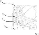
- Fig. 2 shows the upper pin 60 and the upper attachment clip 40 in this locked condition.
- the attachment clip 40 has two side walls which are curved inwards to hold the pin 60 in a positive fit. These side walls are extended by free end pieces which are bent outwards. Hereby, the pin 60 can easily be inserted into the clip 40.
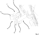
- Fig. 3 shows an embodiment of an attachment clip according to the invention.
- the space between the two side walls 41 and 42 is divided into several sections.
- a first section is formed adjacent the rear wall of the attachment clip 40.
- An elastic element 50 is provided in this first section. When the pin 60 is pressed into the clip 40, the pin 60 rests against this elastic element 50.
- a second section is formed between two pin parts of the side walls, and the pin is received between these two pin parts which are explained in more detail by means of Fig. 4 .
- the inner surfaces of the pin parts 46 and 47 bend inwards so that a pin can be received between them.
- the inner surfaces of these pin parts 46, 47 are concave.
- the pin parts 46, 47 form a pin section 71, and a sponge 50 (not shown in Fig. 4 ) is provided in another section 70 which is located between this pin section 71 and the real wall 45 of the attachment clip. Transition edges are formed between the pin parts and this sponge section 70, because the inner side surfaces of the sponge section 70 are straight, whereas the inner side surfaces of the pin parts 46, 47 are concave. Only one transition edge is marked with reference numeral 80 in Fig. 4 .
- the outer dimensions of the sponge correspond to the inner dimensions of the sponge section so that the sponge can be received in this section.
- the sponge can be fixated in this area by means of an adhesive, for example.
- the side walls 41, 42 further comprise two free end pieces 43 and 44 which bend outwards to form a funnel-shaped opening.
- Intermediate parts 48 and 49 are formed between the pin parts 46, 47 and the end pieces 43, 44.
- the intermediate parts 48, 49 are connected to the pin parts 46, 47 at opposite barrier edges. Only one barrier edge is marked with reference numeral 81 in Fig. 4 .
- the pin is firmly held in the pin section 71 by these barrier edges 81.
- the outer surfaces of the pin parts 46, 47 and the intermediate parts 48, 49 are straight to form a continuous flat outer surface.
- Another edge is formed between the inner surfaces of the intermediate parts 48, 49 and the free end pieces 43, 44.
- This edge is called widening edge, because the clip widens significantly at this point.
- Only one widening edge is marked with reference numeral 82 in Fig. 4 .
- this widening edge 82 is rounded with a relatively large radius.
- the distance between the two widening edges 82 is smaller than the distance between the two barrier edges 81 in this embodiment.
- Fig. 5 shows the approximate boundaries of the four sections between the side walls 41 and 42.
- the first section (sponge section) 70 is located between the real wall 45 and the opposite transition edges 80.
- the second section (pin section) 71 is located between the transition edges 80 and the opposite barrier edges 81.
- a third section 72 is located between the barrier edges 81 and the beginning of the rounded widening edges 82.
- This section 72 can be called intermediate section, because it roughly corresponds to the space between the intermediate parts 48, 49.
- the area around the widening edges 82 is a fourth section 73 which can be called widening section, because the side walls 41, 42 start to bend outwards in this region.
- These four sections form an attachment clip which is longer than typical attachment clips. This advantageously distributes stress on the piece.
Landscapes
- Engineering & Computer Science (AREA)
- Mechanical Engineering (AREA)
- General Engineering & Computer Science (AREA)
- Chemical & Material Sciences (AREA)
- Combustion & Propulsion (AREA)
- Transportation (AREA)
- Connection Of Plates (AREA)
- Insertion Pins And Rivets (AREA)
Abstract
Description
- The present invention refers to an attachment clip for a spoiler system according to the preamble of claim 1 and a spoiler system with at least one attachment clip.
- Spoiler systems can be used to improve vehicle aerodynamics. For example, they can be fitted in the rear region of a vehicle and usually have one or more air guiding elements that lengthen the contours of the vehicle. Rear spoilers of this type can be attached to the vehicle roof or to the side walls. In the field of utility vehicles, side spoiler systems are known which are fastened to the back wall of a cabin of a vehicle or the back wall of a trailer which is connected to the vehicle. Side spoiler systems cover an air gap between a vehicle cabin and a trailer, for example.
- Some elements of such spoiler systems are often adjustable, in particular pivotable. For example, a deflector can be pivoted in order to help persons to reach the back of a vehicle in case a trailer is assembled on the vehicle. The deflector is then adjustable between at least two positions.
US 2015/0102633 A1 describes an exemplary rear spoiler system with adjustable air guiding elements. - The mechanism which holds a deflector in a basic position can comprise a plastic attachment clip on one element and a pin on another element of the spoiler system, wherein the pin is held in the clip when the deflector is in its basic position. For example, the attachment clip can be mounted on a pivoted deflector and the clip embraces a pin which is mounted on a fixed part of the vehicle, or vice versa. When the deflector is pivoted, the pin is pulled out of the clip.
- However, the plastic attachment clip assembled to a spoiler part can sometimes not hold the pin tightly. This leads to movement of the pin within the clip and this clearance can cause squeak and rattle problems which often is one of the most annoying problems of commercial vehicle's customers who drive on long journeys. Not only on rough roads, but also on flat roads the clearance can cause noise. In addition, the plastic attachment clip sometimes has a poor design which cannot absorb vibrations which are caused when the vehicle is travelling on the road. This can also diminish the driver's quality of driving. Furthermore, the clip can deform because of the applied forces due to the repeated opening and closing operations of the attachment mechanism. Vibrations during travelling of the vehicle can then cause micro cracks which grow so that plastic parts can split.
- Therefore, there still is room for improvement of attachment clips used in this type of attachment mechanisms, and it is the object of the invention to provide an attachment clip with a better design.
- According to the invention, this object is achieved by an attachment clip for fixation of a movable air guiding element of a spoiler system for extending the contour of a vehicle according to claim 1. Thereby, the attachment clip comprises two flexible side walls which curve inwards for receiving a pin in a space which is formed between the two side walls. At least two sections are formed in the space between the two side walls, and an elastic element is provided in a first section and a second section is designed to receive the pin in a positive fit, wherein the elastic element contacts the pin. The elastic element can be a sponge, for example. Thus, when a pin is inserted into the attachment clip, the pin lies against the elastic element which can absorb vibrations during the travelling of the vehicle. This reduces squeak and rattle problems and increases the driving comfort. The attachment clip can be made of a flexible plastic material so that the side walls can slightly be bent outwards to receive the pin in the pin section.
- In one embodiment of the invention, the two side walls are connected by a rear wall to form a U-formed cavity and the first section with the elastic element is formed adjacent the rear wall. Consequently, the elastic element is located in front of the rear wall and the pin can be pressed against this elastic element. Preferably, there is a tight fit between the elastic element and the pin so that movement of the pin within the attachment clip is prevented. The rear wall can also be used to mount the attachment clip on an element of the spoiler system, which can be a movable or a fixed part of the spoiler system.
- In its simplest implementation, the two side walls can be formed by two arches which curve inwards. In other embodiments of the invention, the two side walls have a more complex structure comprising different functional parts. For example, the two side walls can comprise two pin parts designed to receive the pin, wherein the pin parts are extended by free end pieces which are bent outwards. Thereby, these free end pieces form a funnel-shaped opening for easily pressing a pin into the space between two pin parts that are curved inwards to hold the pin. In addition, the two side walls can comprise two intermediate parts which are provided between said pin parts and free end pieces. These intermediate parts can be used to enhance the stiffness of the attachment clip.
- In one embodiment of the invention, the inner surfaces of the pin parts are curved inwards, whereas the outer surfaces of the pin parts are straight. Thereby, the width of the pin parts is increased in the front and end regions of the pin parts, which also increases the stiffness of the attachment clip. This stiffness again increases the stability and durability of the attachment clip, which also leads to a higher comfort for the driver of a vehicle. When the attachment clip in this mechanism is repeatedly used to fixate and release a movable air guiding element, there is less wear which again reduces squeak and rattle problems. In addition, the attachment clip is not likely to break.
- Preferably, there is a barrier edge between each of the inner surfaces of the pin parts and the inner surfaces of the intermediate parts, wherein the barrier edges project inwards. Thus, the pin is held in the space between the pin parts by two opposite barrier edges which prevent the pin from slipping out of the clip. Thereby, a precise fitting is achieved and unnecessary motions are kept to a minimum. Displacement motion is inhibited and the disassembly force is increased.
- In one embodiment of the invention, the distance between the opposite inner surfaces of the intermediate parts decreases in the direction of the free end pieces of the two side walls. Thus, the intermediate parts bend inwards which further increases the strength of the side walls. Preferably, the outer surfaces of the intermediate parts are straight, too. The pin parts and the intermediate parts then form a straight continuous outer surface. This prevents the pin parts from bending outwards under forces that occur during the travelling of the vehicle.
- In addition, the attachment clip can comprise a widening edge between each of the inner surfaces of the intermediate parts and the inner surfaces of the free end pieces, wherein said widening edges are rounded. Hereby, the pin can easily be pressed through the gap between the rounded widening edges.
- The invention also encompasses a spoiler system comprising at least one air guiding element which is movable in relation to a second element, wherein an attachment clip and a pin are provided on the air guiding element or the second element, respectively, and the attachment clip is designed to receive the pin in a positive fit. This attachment clip is implemented according to one or more of the described embodiments.
- As mentioned before, the attachment clip can be provided on a fixed or a movable part of the spoiler system. In one embodiment of the invention, the attachment clip is provided on a movable air guiding element, whereas the pin is provided on the second element, for example. In particular, the air guiding element is a deflector of a side spoiler. The air guiding element can be pivoted by means of at least one hinge.
- The corresponding pin is arranged, designed and dimensioned to be received in the attachment clip when the two elements are moved towards each other. Thereby, the distance between opposite barrier edges of the attachment clip is smaller than the diameter of the pin so that the pin can be held between the two curved pin parts of the side walls.
- Further advantageous exemplary embodiments of the invention can be taken from the following detailed description of some exemplary embodiments of the present invention, in particular in conjunction with the figures.
- In the figures:
- Fig. 1
- is a view of a back wall of a vehicle with an adjustable deflector,
- Fig. 2
- is an enlarged view of an attachment mechanism,
- Fig. 3
- is a first enlarged view of one embodiment of an attachment clip according to the invention with a pin,
- Fig. 4
- is a second enlarged view of the attachment clip according to
Fig. 3 , and - Fig. 5
- is a third enlarged view of the attachment clip according to
Fig. 3 . - The
back wall 30 of a vehicle's cabin which is partially shown inFig. 1 comprises an adjustableair guiding element 21. Thisdeflector 21 is pivotable to one side of theback wall 30 by means of three hinges 31,31' and 31". Thereby, thedeflector 21 can be pivoted into the plane of projection so that a person can reach theback wall 30. Two attachment clips are mounted on thedeflector 21. Anupper attachment clip 40 is mounted close to the top edge of thedeflector 21, and a lower attachment clip 40' is mounted close to the bottom edge of thedeflector 21. Two corresponding pins are mounted on adjacent spoiler parts. For example, afirst pin 60 is mounted on thetop spoiler part 20, whereas a second pin 60' is mounted on a bottom spoiler part (not shown). - The
deflector 21 is shown in its basic position. In this position, thepins 60 and 60' are received in the attachment clips 40 and 40' to hold thedeflector 21 in this position during travelling of the vehicle. When thedeflector 21 is swiveled away from theback wall 30, thepins 60, 60' are pulled out of theclips 40, 40'. When thedeflector 21 is swiveled back into its basic position, thepins 60, 60' are pressed into theclips 40, 40' again. -
Fig. 2 shows theupper pin 60 and theupper attachment clip 40 in this locked condition. Theattachment clip 40 has two side walls which are curved inwards to hold thepin 60 in a positive fit. These side walls are extended by free end pieces which are bent outwards. Hereby, thepin 60 can easily be inserted into theclip 40. This arrangement can also be derived from the enlarged view inFig. 3 which shows an embodiment of an attachment clip according to the invention. The space between the twoside walls attachment clip 40. Anelastic element 50 is provided in this first section. When thepin 60 is pressed into theclip 40, thepin 60 rests against thiselastic element 50. - A second section is formed between two pin parts of the side walls, and the pin is received between these two pin parts which are explained in more detail by means of
Fig. 4 . The inner surfaces of thepin parts pin parts pin parts pin section 71, and a sponge 50 (not shown inFig. 4 ) is provided in anothersection 70 which is located between thispin section 71 and thereal wall 45 of the attachment clip. Transition edges are formed between the pin parts and thissponge section 70, because the inner side surfaces of thesponge section 70 are straight, whereas the inner side surfaces of thepin parts reference numeral 80 inFig. 4 . The outer dimensions of the sponge correspond to the inner dimensions of the sponge section so that the sponge can be received in this section. The sponge can be fixated in this area by means of an adhesive, for example. - The
side walls free end pieces Intermediate parts pin parts end pieces intermediate parts pin parts reference numeral 81 inFig. 4 . The pin is firmly held in thepin section 71 by these barrier edges 81. As shown inFig. 4 , the outer surfaces of thepin parts intermediate parts - Another edge is formed between the inner surfaces of the
intermediate parts free end pieces reference numeral 82 inFig. 4 . Preferably, this wideningedge 82 is rounded with a relatively large radius. Furthermore, the distance between the two wideningedges 82 is smaller than the distance between the twobarrier edges 81 in this embodiment. -
Fig. 5 shows the approximate boundaries of the four sections between theside walls real wall 45 and the opposite transition edges 80. The second section (pin section) 71 is located between the transition edges 80 and the opposite barrier edges 81. Athird section 72 is located between the barrier edges 81 and the beginning of the rounded widening edges 82. Thissection 72 can be called intermediate section, because it roughly corresponds to the space between theintermediate parts fourth section 73 which can be called widening section, because theside walls -
- 10
- Spoiler system
- 20
- Second element, top spoiler part
- 21
- Air guiding element, deflector
- 30
- Cabin, back wall
- 31, 31', 31"
- Hinge
- 40, 40'
- Attachment clip
- 41, 42
- Side wall
- 43, 44
- End piece
- 45
- Rear wall
- 46, 47
- Pin part
- 48, 49
- Intermediate part
- 50
- Elastic element, sponge
- 60, 60'
- Pin
- 70
- First section, sponge section
- 71
- Second section, pin section
- 72
- Third section, intermediate section
- 73
- Fourth section, widening section
- 80
- Transition edge
- 81
- Barrier edge
- 82
- Widening edge
Claims (14)
- Attachment clip (40; 40') for fixation of movable air guiding element (21) of spoiler system (10) for extending the contour of a vehicle, wherein the attachment clip (40; 40') comprises two flexible side walls (41; 42) which curve inwards for receiving a pin (60; 60') in a space which is formed between the two side walls (41; 42),
characterized in that
at least two sections (70; 71) are formed in the space between the two side walls (41; 42), and an elastic element (50) is provided in a first section (70) and a second section (71) is designed to receive the pin (60; 60') in a positive fit, wherein the elastic element (50) contacts the pin (60; 60'). - Attachment clip according to claim 1,
characterized in that
the two side walls (40; 40') are connected by a rear wall (45) to form a U-formed cavity, and the first section (70) is formed adjacent the rear wall (45). - Attachment clip according to claim 1 or 2,
characterized in that
the elastic element (50) is a sponge. - Attachment clip according to one of the proceeding claims,
characterized in that
the two side walls (41; 42) comprise two pin parts (46; 47) designed to receive the pin (60; 60'), wherein the pin parts (46; 47) are extended by free end pieces (43; 44) which bend outwards. - Attachment clip according to claim 4,
characterized in that
the two side walls (41; 42) comprise two intermediate parts (48; 49) which are provided between the pin parts (46; 47) and the free end pieces (43; 44). - Attachment clip according to claims 4 or 5,
characterized in that
the inner surfaces of the pin parts (46; 47) are curved inwards, whereas the outer surfaces of the pin parts (46; 47) are straight. - Attachment clip according to one of the proceeding claims 5 or 6,
characterized in that
there is a barrier edge (81) between each of the inner surfaces of the pin parts (46; 47) and the inner surfaces of the intermediate parts (48; 49), wherein the barrier edges (81) project inwards. - Attachment clip according to one of the proceeding claims 5 to 7,
characterized in that
the distance between the opposite inner surfaces of the intermediate parts (48; 49) decreases in the direction of the free end pieces (43; 44) of the two side walls (41; 42). - Attachment clip according to one of the proceeding claims 5 to 7,
characterized in that
there is a widening edge (82) between each of the inner surfaces of the intermediate parts (48; 49) and the inner surfaces of the free end pieces (43; 44), wherein said widening edges (82) are rounded. - Spoiler system (10) comprising at least one air guiding element (21) which is movable in relation to a second element (20), wherein an attachment clip (40; 40') and a pin (60; 60') are provided on the air guiding element (21) or the second element (20), respectively, and the attachment clip (40; 40') is designed to receive the pin (60; 60) in a positive fit,
characterized in that
the attachment clip (40; 40') is implemented according to one or more of the claims 1 to 9. - Spoiler system according to claim 10,
characterized in that
the attachment clip (40; 40') is provided on the movable air guiding element (21), wherein the pin (60; 60') is provided on the second element. - Spoiler system according to one of the proceeding claims 10 or 11,
characterized in that
the air guiding element (21) is pivoted by means of at least one hinge (31; 31'; 31"). - Spoiler system according to claim 7 and one of the proceeding claims 10 to 12,
characterized in that
the distance between opposite barrier edges (81) is smaller than the diameter of the pin (60; 60'). - Spoiler system according to one of the proceeding claims 10 to 13,
characterized in that
the air guiding element (21) is a deflector of a side spoiler.
Priority Applications (1)
| Application Number | Priority Date | Filing Date | Title |
|---|---|---|---|
| EP16153365.8A EP3199431B1 (en) | 2016-01-29 | 2016-01-29 | Attachment clip for spoiler system |
Applications Claiming Priority (1)
| Application Number | Priority Date | Filing Date | Title |
|---|---|---|---|
| EP16153365.8A EP3199431B1 (en) | 2016-01-29 | 2016-01-29 | Attachment clip for spoiler system |
Publications (2)
| Publication Number | Publication Date |
|---|---|
| EP3199431A1 true EP3199431A1 (en) | 2017-08-02 |
| EP3199431B1 EP3199431B1 (en) | 2018-10-03 |
Family
ID=55274991
Family Applications (1)
| Application Number | Title | Priority Date | Filing Date |
|---|---|---|---|
| EP16153365.8A Active EP3199431B1 (en) | 2016-01-29 | 2016-01-29 | Attachment clip for spoiler system |
Country Status (1)
| Country | Link |
|---|---|
| EP (1) | EP3199431B1 (en) |
Cited By (2)
| Publication number | Priority date | Publication date | Assignee | Title |
|---|---|---|---|---|
| IT201900016856A1 (en) * | 2019-09-20 | 2021-03-20 | Iveco Spa | VEHICLE SPOILER INCLUDING AN INTEGRATED LOCK DEVICE |
| US11021875B2 (en) * | 2017-01-26 | 2021-06-01 | Zurn Industries, Llc | Rebar clamp assembly with clip |
Citations (3)
| Publication number | Priority date | Publication date | Assignee | Title |
|---|---|---|---|---|
| US20140339854A1 (en) * | 2011-09-23 | 2014-11-20 | Aero Industries, Inc. | Drag Reducing Device |
| US20150102633A1 (en) | 2012-06-02 | 2015-04-16 | Wabco Gmbh | Rear Spoiler System for a Vehicle |
| US20150219132A1 (en) * | 2014-02-01 | 2015-08-06 | GM Global Technology Operations LLC | Retaining clip for at least one elongate element |
-
2016
- 2016-01-29 EP EP16153365.8A patent/EP3199431B1/en active Active
Patent Citations (3)
| Publication number | Priority date | Publication date | Assignee | Title |
|---|---|---|---|---|
| US20140339854A1 (en) * | 2011-09-23 | 2014-11-20 | Aero Industries, Inc. | Drag Reducing Device |
| US20150102633A1 (en) | 2012-06-02 | 2015-04-16 | Wabco Gmbh | Rear Spoiler System for a Vehicle |
| US20150219132A1 (en) * | 2014-02-01 | 2015-08-06 | GM Global Technology Operations LLC | Retaining clip for at least one elongate element |
Cited By (3)
| Publication number | Priority date | Publication date | Assignee | Title |
|---|---|---|---|---|
| US11021875B2 (en) * | 2017-01-26 | 2021-06-01 | Zurn Industries, Llc | Rebar clamp assembly with clip |
| IT201900016856A1 (en) * | 2019-09-20 | 2021-03-20 | Iveco Spa | VEHICLE SPOILER INCLUDING AN INTEGRATED LOCK DEVICE |
| WO2021053610A1 (en) * | 2019-09-20 | 2021-03-25 | Iveco S.P.A. | Spoiler for a vehicle comprising an integrated locking device |
Also Published As
| Publication number | Publication date |
|---|---|
| EP3199431B1 (en) | 2018-10-03 |
Similar Documents
| Publication | Publication Date | Title |
|---|---|---|
| KR101366891B1 (en) | Front spoiler for a motor vehicle | |
| US7159267B2 (en) | Cap for wiper connector | |
| US7387331B2 (en) | Air guiding system for a vehicle | |
| US20130255025A1 (en) | Wiper blade assembly | |
| JP4809420B2 (en) | Wiper blade | |
| AU2009293829B2 (en) | Frame molding | |
| US20050241259A1 (en) | Sill panel for a motor vehicle | |
| US20160200265A1 (en) | Trim member attachment structure | |
| EP3199431B1 (en) | Attachment clip for spoiler system | |
| JP6800654B2 (en) | Support elements, automotive wiper blades and windshield wipers | |
| US9073419B2 (en) | Wind deflector | |
| JP3123564U (en) | Curtain rail and curtain set using the curtain rail | |
| JP3993952B2 (en) | Vehicle wiper device | |
| CN109927645B (en) | Front wall upper decoration | |
| US10688969B2 (en) | Yoke for a drive arm of a windscreen wiper | |
| US9701226B2 (en) | Vehicle seat with a crash-modified panel holder | |
| EP2899078B1 (en) | Multifunctional windshield wiper connection structure | |
| US9156434B2 (en) | Webbing exit protection boot for a webbing of a seat belt and seat belt system | |
| US20080258508A1 (en) | Wind Deflector for a Sliding Roof | |
| JP4453141B2 (en) | Door frame molding structure | |
| US7127774B2 (en) | Wiper arm and blade assembly having tension inducing projections | |
| US11091125B2 (en) | Wiper apparatus and vehicle body rear structure | |
| KR102162656B1 (en) | Console for automobile | |
| CN109987152A (en) | Body construction | |
| JP6341817B2 (en) | Inner mirror structure for vehicles |
Legal Events
| Date | Code | Title | Description |
|---|---|---|---|
| PUAI | Public reference made under article 153(3) epc to a published international application that has entered the european phase |
Free format text: ORIGINAL CODE: 0009012 |
|
| STAA | Information on the status of an ep patent application or granted ep patent |
Free format text: STATUS: THE APPLICATION HAS BEEN PUBLISHED |
|
| AK | Designated contracting states |
Kind code of ref document: A1 Designated state(s): AL AT BE BG CH CY CZ DE DK EE ES FI FR GB GR HR HU IE IS IT LI LT LU LV MC MK MT NL NO PL PT RO RS SE SI SK SM TR |
|
| AX | Request for extension of the european patent |
Extension state: BA ME |
|
| STAA | Information on the status of an ep patent application or granted ep patent |
Free format text: STATUS: REQUEST FOR EXAMINATION WAS MADE |
|
| 17P | Request for examination filed |
Effective date: 20180202 |
|
| RBV | Designated contracting states (corrected) |
Designated state(s): AL AT BE BG CH CY CZ DE DK EE ES FI FR GB GR HR HU IE IS IT LI LT LU LV MC MK MT NL NO PL PT RO RS SE SI SK SM TR |
|
| GRAP | Despatch of communication of intention to grant a patent |
Free format text: ORIGINAL CODE: EPIDOSNIGR1 |
|
| STAA | Information on the status of an ep patent application or granted ep patent |
Free format text: STATUS: GRANT OF PATENT IS INTENDED |
|
| INTG | Intention to grant announced |
Effective date: 20180628 |
|
| GRAS | Grant fee paid |
Free format text: ORIGINAL CODE: EPIDOSNIGR3 |
|
| GRAA | (expected) grant |
Free format text: ORIGINAL CODE: 0009210 |
|
| STAA | Information on the status of an ep patent application or granted ep patent |
Free format text: STATUS: THE PATENT HAS BEEN GRANTED |
|
| AK | Designated contracting states |
Kind code of ref document: B1 Designated state(s): AL AT BE BG CH CY CZ DE DK EE ES FI FR GB GR HR HU IE IS IT LI LT LU LV MC MK MT NL NO PL PT RO RS SE SI SK SM TR |
|
| REG | Reference to a national code |
Ref country code: GB Ref legal event code: FG4D |
|
| REG | Reference to a national code |
Ref country code: CH Ref legal event code: EP Ref country code: AT Ref legal event code: REF Ref document number: 1048290 Country of ref document: AT Kind code of ref document: T Effective date: 20181015 |
|
| REG | Reference to a national code |
Ref country code: IE Ref legal event code: FG4D Ref country code: DE Ref legal event code: R096 Ref document number: 602016006116 Country of ref document: DE |
|
| REG | Reference to a national code |
Ref country code: NL Ref legal event code: MP Effective date: 20181003 |
|
| REG | Reference to a national code |
Ref country code: LT Ref legal event code: MG4D |
|
| REG | Reference to a national code |
Ref country code: AT Ref legal event code: MK05 Ref document number: 1048290 Country of ref document: AT Kind code of ref document: T Effective date: 20181003 |
|
| PG25 | Lapsed in a contracting state [announced via postgrant information from national office to epo] |
Ref country code: NL Free format text: LAPSE BECAUSE OF FAILURE TO SUBMIT A TRANSLATION OF THE DESCRIPTION OR TO PAY THE FEE WITHIN THE PRESCRIBED TIME-LIMIT Effective date: 20181003 |
|
| PG25 | Lapsed in a contracting state [announced via postgrant information from national office to epo] |
Ref country code: FI Free format text: LAPSE BECAUSE OF FAILURE TO SUBMIT A TRANSLATION OF THE DESCRIPTION OR TO PAY THE FEE WITHIN THE PRESCRIBED TIME-LIMIT Effective date: 20181003 Ref country code: IS Free format text: LAPSE BECAUSE OF FAILURE TO SUBMIT A TRANSLATION OF THE DESCRIPTION OR TO PAY THE FEE WITHIN THE PRESCRIBED TIME-LIMIT Effective date: 20190203 Ref country code: AT Free format text: LAPSE BECAUSE OF FAILURE TO SUBMIT A TRANSLATION OF THE DESCRIPTION OR TO PAY THE FEE WITHIN THE PRESCRIBED TIME-LIMIT Effective date: 20181003 Ref country code: LV Free format text: LAPSE BECAUSE OF FAILURE TO SUBMIT A TRANSLATION OF THE DESCRIPTION OR TO PAY THE FEE WITHIN THE PRESCRIBED TIME-LIMIT Effective date: 20181003 Ref country code: HR Free format text: LAPSE BECAUSE OF FAILURE TO SUBMIT A TRANSLATION OF THE DESCRIPTION OR TO PAY THE FEE WITHIN THE PRESCRIBED TIME-LIMIT Effective date: 20181003 Ref country code: CZ Free format text: LAPSE BECAUSE OF FAILURE TO SUBMIT A TRANSLATION OF THE DESCRIPTION OR TO PAY THE FEE WITHIN THE PRESCRIBED TIME-LIMIT Effective date: 20181003 Ref country code: NO Free format text: LAPSE BECAUSE OF FAILURE TO SUBMIT A TRANSLATION OF THE DESCRIPTION OR TO PAY THE FEE WITHIN THE PRESCRIBED TIME-LIMIT Effective date: 20190103 Ref country code: PL Free format text: LAPSE BECAUSE OF FAILURE TO SUBMIT A TRANSLATION OF THE DESCRIPTION OR TO PAY THE FEE WITHIN THE PRESCRIBED TIME-LIMIT Effective date: 20181003 Ref country code: BG Free format text: LAPSE BECAUSE OF FAILURE TO SUBMIT A TRANSLATION OF THE DESCRIPTION OR TO PAY THE FEE WITHIN THE PRESCRIBED TIME-LIMIT Effective date: 20190103 Ref country code: ES Free format text: LAPSE BECAUSE OF FAILURE TO SUBMIT A TRANSLATION OF THE DESCRIPTION OR TO PAY THE FEE WITHIN THE PRESCRIBED TIME-LIMIT Effective date: 20181003 Ref country code: LT Free format text: LAPSE BECAUSE OF FAILURE TO SUBMIT A TRANSLATION OF THE DESCRIPTION OR TO PAY THE FEE WITHIN THE PRESCRIBED TIME-LIMIT Effective date: 20181003 |
|
| PG25 | Lapsed in a contracting state [announced via postgrant information from national office to epo] |
Ref country code: PT Free format text: LAPSE BECAUSE OF FAILURE TO SUBMIT A TRANSLATION OF THE DESCRIPTION OR TO PAY THE FEE WITHIN THE PRESCRIBED TIME-LIMIT Effective date: 20190203 Ref country code: RS Free format text: LAPSE BECAUSE OF FAILURE TO SUBMIT A TRANSLATION OF THE DESCRIPTION OR TO PAY THE FEE WITHIN THE PRESCRIBED TIME-LIMIT Effective date: 20181003 Ref country code: SE Free format text: LAPSE BECAUSE OF FAILURE TO SUBMIT A TRANSLATION OF THE DESCRIPTION OR TO PAY THE FEE WITHIN THE PRESCRIBED TIME-LIMIT Effective date: 20181003 Ref country code: GR Free format text: LAPSE BECAUSE OF FAILURE TO SUBMIT A TRANSLATION OF THE DESCRIPTION OR TO PAY THE FEE WITHIN THE PRESCRIBED TIME-LIMIT Effective date: 20190104 Ref country code: AL Free format text: LAPSE BECAUSE OF FAILURE TO SUBMIT A TRANSLATION OF THE DESCRIPTION OR TO PAY THE FEE WITHIN THE PRESCRIBED TIME-LIMIT Effective date: 20181003 |
|
| REG | Reference to a national code |
Ref country code: DE Ref legal event code: R097 Ref document number: 602016006116 Country of ref document: DE |
|
| PG25 | Lapsed in a contracting state [announced via postgrant information from national office to epo] |
Ref country code: IT Free format text: LAPSE BECAUSE OF FAILURE TO SUBMIT A TRANSLATION OF THE DESCRIPTION OR TO PAY THE FEE WITHIN THE PRESCRIBED TIME-LIMIT Effective date: 20181003 Ref country code: DK Free format text: LAPSE BECAUSE OF FAILURE TO SUBMIT A TRANSLATION OF THE DESCRIPTION OR TO PAY THE FEE WITHIN THE PRESCRIBED TIME-LIMIT Effective date: 20181003 |
|
| PLBE | No opposition filed within time limit |
Free format text: ORIGINAL CODE: 0009261 |
|
| STAA | Information on the status of an ep patent application or granted ep patent |
Free format text: STATUS: NO OPPOSITION FILED WITHIN TIME LIMIT |
|
| PG25 | Lapsed in a contracting state [announced via postgrant information from national office to epo] |
Ref country code: MC Free format text: LAPSE BECAUSE OF FAILURE TO SUBMIT A TRANSLATION OF THE DESCRIPTION OR TO PAY THE FEE WITHIN THE PRESCRIBED TIME-LIMIT Effective date: 20181003 Ref country code: SM Free format text: LAPSE BECAUSE OF FAILURE TO SUBMIT A TRANSLATION OF THE DESCRIPTION OR TO PAY THE FEE WITHIN THE PRESCRIBED TIME-LIMIT Effective date: 20181003 Ref country code: EE Free format text: LAPSE BECAUSE OF FAILURE TO SUBMIT A TRANSLATION OF THE DESCRIPTION OR TO PAY THE FEE WITHIN THE PRESCRIBED TIME-LIMIT Effective date: 20181003 Ref country code: RO Free format text: LAPSE BECAUSE OF FAILURE TO SUBMIT A TRANSLATION OF THE DESCRIPTION OR TO PAY THE FEE WITHIN THE PRESCRIBED TIME-LIMIT Effective date: 20181003 Ref country code: SK Free format text: LAPSE BECAUSE OF FAILURE TO SUBMIT A TRANSLATION OF THE DESCRIPTION OR TO PAY THE FEE WITHIN THE PRESCRIBED TIME-LIMIT Effective date: 20181003 |
|
| REG | Reference to a national code |
Ref country code: CH Ref legal event code: PL |
|
| 26N | No opposition filed |
Effective date: 20190704 |
|
| PG25 | Lapsed in a contracting state [announced via postgrant information from national office to epo] |
Ref country code: LU Free format text: LAPSE BECAUSE OF NON-PAYMENT OF DUE FEES Effective date: 20190129 |
|
| REG | Reference to a national code |
Ref country code: BE Ref legal event code: MM Effective date: 20190131 |
|
| REG | Reference to a national code |
Ref country code: IE Ref legal event code: MM4A |
|
| PG25 | Lapsed in a contracting state [announced via postgrant information from national office to epo] |
Ref country code: SI Free format text: LAPSE BECAUSE OF FAILURE TO SUBMIT A TRANSLATION OF THE DESCRIPTION OR TO PAY THE FEE WITHIN THE PRESCRIBED TIME-LIMIT Effective date: 20181003 |
|
| PG25 | Lapsed in a contracting state [announced via postgrant information from national office to epo] |
Ref country code: BE Free format text: LAPSE BECAUSE OF NON-PAYMENT OF DUE FEES Effective date: 20190131 |
|
| PG25 | Lapsed in a contracting state [announced via postgrant information from national office to epo] |
Ref country code: LI Free format text: LAPSE BECAUSE OF NON-PAYMENT OF DUE FEES Effective date: 20190131 Ref country code: CH Free format text: LAPSE BECAUSE OF NON-PAYMENT OF DUE FEES Effective date: 20190131 |
|
| PG25 | Lapsed in a contracting state [announced via postgrant information from national office to epo] |
Ref country code: IE Free format text: LAPSE BECAUSE OF NON-PAYMENT OF DUE FEES Effective date: 20190129 |
|
| PGFP | Annual fee paid to national office [announced via postgrant information from national office to epo] |
Ref country code: FR Payment date: 20191226 Year of fee payment: 5 |
|
| PG25 | Lapsed in a contracting state [announced via postgrant information from national office to epo] |
Ref country code: MT Free format text: LAPSE BECAUSE OF NON-PAYMENT OF DUE FEES Effective date: 20190129 |
|
| PG25 | Lapsed in a contracting state [announced via postgrant information from national office to epo] |
Ref country code: CY Free format text: LAPSE BECAUSE OF FAILURE TO SUBMIT A TRANSLATION OF THE DESCRIPTION OR TO PAY THE FEE WITHIN THE PRESCRIBED TIME-LIMIT Effective date: 20181003 |
|
| PG25 | Lapsed in a contracting state [announced via postgrant information from national office to epo] |
Ref country code: HU Free format text: LAPSE BECAUSE OF FAILURE TO SUBMIT A TRANSLATION OF THE DESCRIPTION OR TO PAY THE FEE WITHIN THE PRESCRIBED TIME-LIMIT; INVALID AB INITIO Effective date: 20160129 |
|
| PG25 | Lapsed in a contracting state [announced via postgrant information from national office to epo] |
Ref country code: FR Free format text: LAPSE BECAUSE OF NON-PAYMENT OF DUE FEES Effective date: 20210131 |
|
| PG25 | Lapsed in a contracting state [announced via postgrant information from national office to epo] |
Ref country code: MK Free format text: LAPSE BECAUSE OF FAILURE TO SUBMIT A TRANSLATION OF THE DESCRIPTION OR TO PAY THE FEE WITHIN THE PRESCRIBED TIME-LIMIT Effective date: 20181003 |
|
| P01 | Opt-out of the competence of the unified patent court (upc) registered |
Effective date: 20230625 |
|
| PGFP | Annual fee paid to national office [announced via postgrant information from national office to epo] |
Ref country code: GB Payment date: 20231218 Year of fee payment: 9 |
|
| PGFP | Annual fee paid to national office [announced via postgrant information from national office to epo] |
Ref country code: DE Payment date: 20231215 Year of fee payment: 9 |
|
| PGFP | Annual fee paid to national office [announced via postgrant information from national office to epo] |
Ref country code: TR Payment date: 20240116 Year of fee payment: 9 |