EP3199137A1 - Hand rehabilitation device with fixing mechanism - Google Patents
Hand rehabilitation device with fixing mechanism Download PDFInfo
- Publication number
- EP3199137A1 EP3199137A1 EP16382037.6A EP16382037A EP3199137A1 EP 3199137 A1 EP3199137 A1 EP 3199137A1 EP 16382037 A EP16382037 A EP 16382037A EP 3199137 A1 EP3199137 A1 EP 3199137A1
- Authority
- EP
- European Patent Office
- Prior art keywords
- thumb
- fixing
- elongated member
- joint
- along
- Prior art date
- Legal status (The legal status is an assumption and is not a legal conclusion. Google has not performed a legal analysis and makes no representation as to the accuracy of the status listed.)
- Withdrawn
Links
- 210000003813 thumb Anatomy 0.000 claims abstract description 98
- 210000003811 finger Anatomy 0.000 description 17
- 230000001771 impaired effect Effects 0.000 description 6
- 230000006835 compression Effects 0.000 description 4
- 238000007906 compression Methods 0.000 description 4
- 210000003414 extremity Anatomy 0.000 description 3
- 230000005540 biological transmission Effects 0.000 description 2
- 210000004247 hand Anatomy 0.000 description 2
- 238000003780 insertion Methods 0.000 description 2
- 230000037431 insertion Effects 0.000 description 2
- 210000004932 little finger Anatomy 0.000 description 2
- 238000011084 recovery Methods 0.000 description 2
- 206010033799 Paralysis Diseases 0.000 description 1
- 208000018737 Parkinson disease Diseases 0.000 description 1
- 208000006011 Stroke Diseases 0.000 description 1
- 208000030886 Traumatic Brain injury Diseases 0.000 description 1
- 210000004556 brain Anatomy 0.000 description 1
- 230000000295 complement effect Effects 0.000 description 1
- 238000009795 derivation Methods 0.000 description 1
- -1 dimensions Substances 0.000 description 1
- 238000006073 displacement reaction Methods 0.000 description 1
- 230000000694 effects Effects 0.000 description 1
- 238000011156 evaluation Methods 0.000 description 1
- 239000000463 material Substances 0.000 description 1
- 238000005259 measurement Methods 0.000 description 1
- 238000012544 monitoring process Methods 0.000 description 1
- 230000001537 neural effect Effects 0.000 description 1
- 231100000878 neurological injury Toxicity 0.000 description 1
- 239000007787 solid Substances 0.000 description 1
- 208000020431 spinal cord injury Diseases 0.000 description 1
- 230000004936 stimulating effect Effects 0.000 description 1
- 238000002560 therapeutic procedure Methods 0.000 description 1
- 230000009529 traumatic brain injury Effects 0.000 description 1
- 210000000707 wrist Anatomy 0.000 description 1
Images




Classifications
-
- A—HUMAN NECESSITIES
- A61—MEDICAL OR VETERINARY SCIENCE; HYGIENE
- A61H—PHYSICAL THERAPY APPARATUS, e.g. DEVICES FOR LOCATING OR STIMULATING REFLEX POINTS IN THE BODY; ARTIFICIAL RESPIRATION; MASSAGE; BATHING DEVICES FOR SPECIAL THERAPEUTIC OR HYGIENIC PURPOSES OR SPECIFIC PARTS OF THE BODY
- A61H1/00—Apparatus for passive exercising; Vibrating apparatus; Chiropractic devices, e.g. body impacting devices, external devices for briefly extending or aligning unbroken bones
- A61H1/02—Stretching or bending or torsioning apparatus for exercising
- A61H1/0274—Stretching or bending or torsioning apparatus for exercising for the upper limbs
- A61H1/0285—Hand
- A61H1/0288—Fingers
-
- A—HUMAN NECESSITIES
- A61—MEDICAL OR VETERINARY SCIENCE; HYGIENE
- A61H—PHYSICAL THERAPY APPARATUS, e.g. DEVICES FOR LOCATING OR STIMULATING REFLEX POINTS IN THE BODY; ARTIFICIAL RESPIRATION; MASSAGE; BATHING DEVICES FOR SPECIAL THERAPEUTIC OR HYGIENIC PURPOSES OR SPECIFIC PARTS OF THE BODY
- A61H2201/00—Characteristics of apparatus not provided for in the preceding codes
- A61H2201/01—Constructive details
- A61H2201/0119—Support for the device
- A61H2201/0153—Support for the device hand-held
-
- A—HUMAN NECESSITIES
- A61—MEDICAL OR VETERINARY SCIENCE; HYGIENE
- A61H—PHYSICAL THERAPY APPARATUS, e.g. DEVICES FOR LOCATING OR STIMULATING REFLEX POINTS IN THE BODY; ARTIFICIAL RESPIRATION; MASSAGE; BATHING DEVICES FOR SPECIAL THERAPEUTIC OR HYGIENIC PURPOSES OR SPECIFIC PARTS OF THE BODY
- A61H2201/00—Characteristics of apparatus not provided for in the preceding codes
- A61H2201/01—Constructive details
- A61H2201/0192—Specific means for adjusting dimensions
-
- A—HUMAN NECESSITIES
- A61—MEDICAL OR VETERINARY SCIENCE; HYGIENE
- A61H—PHYSICAL THERAPY APPARATUS, e.g. DEVICES FOR LOCATING OR STIMULATING REFLEX POINTS IN THE BODY; ARTIFICIAL RESPIRATION; MASSAGE; BATHING DEVICES FOR SPECIAL THERAPEUTIC OR HYGIENIC PURPOSES OR SPECIFIC PARTS OF THE BODY
- A61H2201/00—Characteristics of apparatus not provided for in the preceding codes
- A61H2201/12—Driving means
- A61H2201/1207—Driving means with electric or magnetic drive
- A61H2201/1215—Rotary drive
-
- A—HUMAN NECESSITIES
- A61—MEDICAL OR VETERINARY SCIENCE; HYGIENE
- A61H—PHYSICAL THERAPY APPARATUS, e.g. DEVICES FOR LOCATING OR STIMULATING REFLEX POINTS IN THE BODY; ARTIFICIAL RESPIRATION; MASSAGE; BATHING DEVICES FOR SPECIAL THERAPEUTIC OR HYGIENIC PURPOSES OR SPECIFIC PARTS OF THE BODY
- A61H2201/00—Characteristics of apparatus not provided for in the preceding codes
- A61H2201/16—Physical interface with patient
- A61H2201/1602—Physical interface with patient kind of interface, e.g. head rest, knee support or lumbar support
- A61H2201/165—Wearable interfaces
Definitions
- the present invention relates to the field of devices for rehabilitation of impaired limbs and, in particular, to devices for rehabilitation of impaired hands and fingers.
- Finger function can be lost or damaged as a result of neurological injuries, such as stroke, spinal cord injuries, traumatic brain injuries or Parkinson disease.
- stroke may cause paralysis of one side of the body.
- Examples of damaged finger functions are failure to extend fingers, poor finger coordination, loss of finger independence, poor grasping or manipulation ability and inability to control constant grip force. Since the brain has certain capacity to reorganize the damaged neural connections, a partial (or even complete) recovery of the damaged functions is possible.
- exoskeletons are robotic skeletons that externally embrace a limb or part of the body.
- exoskeletons are robotic skeletons that externally embrace a limb or part of the body.
- United States patent US-5516249-A describes an exoskeletal control apparatus based on a glove framework into which a hand can be inserted.
- a similar system is disclosed in United States patent US-8574178-B2 .
- a common problem shared by conventional hand rehabilitation devices is the adjustment of the thumb, because the size and shape of the thumb varies significantly from person to person.
- Krebs HI, Volpe BT, Williams D, et al. in "Robot-aided neurorehabilitation: a robot for wrist rehabilitation", IEEE TransNeural Syst Rehabil Eng 2007; 15:327-335 disclose a device that has no thumb adjustment.
- This problem has been address by Takahashi CD, Der-Yeghiaian L, Le VH and Cramer SC in "A robotic device for hand motor therapy after stroke", International Conference on Rehabilitation Robotics, ICORR Proceedings; 28 June-1 July 2005; Chicago, USA .
- This device includes adjustment of the thumb, but only to a certain extent, because it only provides 1 degree of freedom (DOF).
- DOF degree of freedom
- a hand rehabilitation device comprising a thumb rehabilitation assembly and a thumb fixing mechanism coupled to said thumb rehabilitation assembly for the anthropometric positioning of a thumb of a user.
- the thumb fixing mechanism comprises: a fixing/releasing mechanism comprising an elongated member; a first part comprising a through hole for sliding said part along said elongated member; a joint comprising two parallel hollow canals that go through the joint from a first side to a second side thereof, opposite to the first side, said joint comprising a through hole configured to mount the joint concentrically along said elongated member until the joint is supported on said first part; guiding means comprising two sections nserted along respective said two parallel hollow canals, said two sections being capable of sliding along said canals, wherein one end of each of said two sections are connected to said thumb rehabilitation assembly; a nut configured to be concentrically mounted on said joint along said elongated member; wherein the fixing/releasing mechanism is configured to manually switch from a first position to a second position
- the fixing/releasing mechanism of said thumb fixing mechanism further comprises a lever having an end terminated in a cam-like mechanism and a part, wherein one end of said elongated member is coupled to said cam-like mechanism, said part being configured to slide along said elongated member until it contacts said cam-like mechanism, said two positions of the fixing/releasing mechanism being actioned by said lever.
- the end of said elongated member coupled to said cam-like mechanism comprises two protrusions that exceed the section of the elongated member and said cam-like mechanism comprises respective holes aligned with each other, each of said two protrusions being configured to couple with a corresponding hole.
- the fixing/releasing mechanism of said thumb fixing mechanism is formed by a screw, said screw comprising said elongated member.
- the joint of said thumb fixing mechanism comprises: a second part having a through hole, the second part being configured to be inserted along said elongated member, that receives a convex surface of said part until it is supported on said first part; and first and second swivels of spherical cap shape, having respective through holes, said first and second swivels being configured to couple with each other at their respective non-convex sides, and configured to be inserted along said elongated member through said through holes until they are supported on said second part.
- said plurality of independent movements for adjusting said thumb rehabilitation assembly are performed thanks to five contact surfaces that are released in said first unlocked position of the fixing/release mechanism, said contact surfaces being: a first contact surface between said first part and said second part; a second contact surface between said second part and said lower swivel; a third contact surface between said lower swivel and said upper swivel; a fourth contact surface between said upper swivel and said nut; and a fifth surface between said first part and said fixing/releasing mechanism.
- the guiding means of said thumb fixing mechanism comprises two curved sections, thus allowing anthropometric positioning of the thumb.
- the mechanism of the invention permits to adjust 4 degrees of freedom and only 1 lock is needed to block them all.
- the term “approximately” and terms of its family should be understood as indicating values very near to those which accompany the aforementioned term. That is to say, a deviation within reasonable limits from an exact value should be accepted, because a skilled person in the art will understand that such a deviation from the values indicated is inevitable due to measurement inaccuracies, etc. The same applies to the terms “about” and “around” and “substantially”.
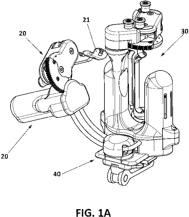
- Figures 1A-1C and 2 show respective views of an exemplary portable hand rehabilitation device 30 comprising a thumb rehabilitation assembly 20.
- the device 30 comprises a thumb fixing mechanism 40 according to an embodiment of the invention.
- the thumb fixing mechanism 40 is not limited to this exemplary hand rehabilitation device 30. What is more, the thumb fixing mechanism 40 is not limited to this exemplary thumb rehabilitation assembly 20.
- the thumb fixing mechanism 40 of this invention is to be used in any hand rehabilitation device requiring adjustment of a part or group of parts dedicated to the rehabilitation of a thumb, such as the thumb rehabilitation assembly 20 illustrated in figures 1A-1C and 2 .
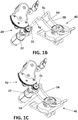
- Figures 1B and 1C explain how the rehabilitation assembly 20 is attached to the locking mechanism 40.
- the two rod ends 5x 5y (described later and shown in detail in figure 3A ) are press-fit to corresponding matching receptacles 21 22 on the rehabilitation assembly 20.
- the exemplary hand rehabilitation device 30 is configured to be grasped by the hand to be trained or rehabilitated, in such a way that the palm, fingers and thumb (inner part of the hand) surround the grasped device 30.
- the inner part of the fingers and thumb are disposed on several supports or "finger rests" (for example the thumb is supported on rest or support 21).
- the remaining supports for the fingers are not explained because they are not relevant for the present invention.
- the thumb support 21 is attached to a structure 20 which holds the transmission mechanism for that support 21.
- the supports or rests for the thumb and fingers are moved, actuated by one or more motors, provoking the flexion/extension of the thumb and fingers supported on the corresponding supports or rests.
- device 30 permits independent rehabilitation of the thumb by means of support 21 and corresponding transmission mechanism. Rehabilitation of the index, middle ring and little fingers is out of the scope of the present invention.
- the exemplary device 30 permits passive rotation of finger (and thumb) supports for self-alignment with hands of varying sizes.
- Figure 3A shows a break-up of thumb fixing mechanism 40 (or thumb lock mechanism) according to a possible embodiment of the invention.
- Figure 3B shows the mechanism once assembled.
- the mechanism 40 serves at adjusting the initial position of the thumb prior to starting a rehabilitation session.
- the thumb size may vary from person to person.
- the mechanism 40 works both of a right hand thumb and of a left hand thumb.
- the mechanism 40 provides a joint 8 that allows the adjustment of four independent positions of the bent rod (referred to as 5A, 5B, 5x, 5y) where the thumb rehabilitation assembly is attached, thus providing 4 degrees of freedom (DOF). This way, the thumb assembly can be adjusted in 4 different angles.
- the 4 DOF can all be locked/unlocked with a single movement or click of the mechanism.
- Mechanism 40 is based on a joint 8 composed of upper and lower halves defining two cylindrical canals in between, in such a way that guiding means, such as a curved rail or rod, can move (slide) along the canals, between the two halves of the joint, or be clamped (fixed) in place there between.
- guiding means such as a curved rail or rod
- the shape of the curved sliding rail is such that it allows anthropometric positioning of the thumb with respect to a large range of human hand sizes.
- Mechanism 40 comprises several parts. It comprises a quick fixing/releasing mechanism 10.
- the fixing/releasing 10 has an elongated member, such as a bolt, stick or skewer 1.
- one of the ends of the elongated member 1 forms two protrusions 101 102 that exceed the section of the elongated member.
- the protrusions 101 102 are preferably perpendicular to the elongated member 1 and aligned with each other, that is to say, forming a 180o angle with respect to each other.
- member 1 has a "T" shape or hammer shape.
- the fixing/releasing 10 may comprise a part 12 having a thru hole along which the elongated member 1 can slide with clearance.
- part 12 enters the elongated member 1 through its end not ended in two protrusions 101 102.
- the fixing/releasing 10 of this embodiment also comprises an arm 11 having an end terminated in a cam or rotating mechanism.
- the elongated member 1 is connected, preferably by means of the protrusions 101 102, to this cam or rotating mechanism.
- This cam-like mechanism is implemented in this embodiment by two members 111 112 defining respective holes which are aligned with each other, defining a rotation axis.
- the two members 111 112 form a single part with the arm 11. Since the arm 11 works as a lever, both terms "arm” and “lever” are used equally to refer to element 11.
- the quick fixing/releasing mechanism 10 has two positions actioned by arm 11 that will be explained later in this text.
- Protrusions 101 102 of the elongated member 1 couple with corresponding holes in the cam or rotating mechanism 111 112.
- the cam-like mechanism 111 112 of lever 11 makes the elongated member 1 move up-down depending on the angle of the lever 11.
- Part 12 has a surface (labeled with dotted arrows in figure 9D ) that is in contact with the cam mechanism 111 112 in lever 11.
- Mechanism 40 also comprises a part or support 2.
- Part 2 is a fixed part acting as a reference for all other parts, which are connected to part 2.
- part 2 represents the geometry required at the hand rehabilitation device to which the thumb lock is connected to, that is to say, part 2 needs to align with a particular hand rehabilitation device to which this thumb lock may be connected to.
- the geometry of part 2, specially its outer shape may vary in alternative embodiments, depending on the robot to which the thumb lock mechanism is connected to.
- Part or support 2 is configured to be inserted along the elongated member 1, preferably once part 12 has been inserted.
- Part 2 may take any shape, provided it has a thru hole that enables part 2 to be inserted along the elongated member 1, as shown for example in figures 3A and 3B .
- part 2 could be fixed to part 12. So, part 12 is coupled to part 2. In particular, the upper surface of part 12 is in contact with the lower surface of part 2. As already mentioned, part 2 plays the role of being a reference for the other parts.
- the other parts involved in the locking mechanism (parts 3, 4, 6, 7, as described later) are supported on part 2 as mechanism is built by sliding those parts along elongated member 1.
- Part 2 is preferably an independent part with respect to the elongated member 1 (and mechanism 10, if any). Alternatively, it could be, together with part 12, an integral part of the lower portion of the elongated member 1. In use of the mechanism, part 2 does not move.
- Figure 5 shows one view of part 2 according to the embodiment illustrated in figures 3A-3B . The thru hole required for sliding part 2 along the elongated member 1 is shown.
- the particular implementation of part 2 illustrated in figure 5 has two straight parallel sides and two curved sides. However, this shape may vary, depending on the robot to which to thumb lock mechanism is connected.
- Mechanism 40 also has a joint 8 that, when assembled, takes the form of a housing. It is made of three pieces or parts 3 4 6.
- Joint or housing 8 comprises a substantially semispherical part 3.
- Part 3 defines a spherical cap shape receptacle. It also has a smaller normal hole to let the elongated member 1 thru.
- Figure 6 shows two views of part 3 according to the embodiment illustrated in figures 3A-3B .
- Part 3 has a through hole 3C in its central position that permits the insertion of part 3 along the elongated member 1. Therefore, the through hole 3C of part 3 has substantially the same section as the diameter of the elongated member 1.
- part 3 In use of the mechanism 40, when part 3 is inserted along the elongated member 1, the elongated member 1 receives the convex surface of part 3. Part 3 is then placed on part 2, which has previously been placed on part se 12. In order for a correct adjustment of part 3 on top of part 2, part 3 should be manufactured so that there is no interference in order to reduce friction during readjustment.
- parts 3 and 2 do not move and are "fixed” together with surface friction labeled "I” (seen for example in Fig 9A (unlocked position) and in Fig. 9C (locked position)).
- Housing 8 also comprises two swivels or rotating joints 4 6.
- Figures 7 and 8 respectively show views of swivels 4 and 6 according to the embodiment illustrated in figures 3A-3B .
- Swivels or rotating joints 4 6 are of spherical cap shape.
- Swivels 4 6 also have a through hole 4C 6C in its central position that permits their insertion along the elongated member 1.
- Swivels 4 6 are substantially complementary, in such a way that when they are coupled to each other in their non-convex side, they form a substantially closed part perforated by a through hole.
- the hollow has truncated-cone shape.
- Swivels 4 6 are solid parts on which two substantially parallel canals 4A 4B 6A 6B have been done.
- Part 4 has a conical hole.
- Part 6 has a "spherical cap” hole. Therefore there is a lower swivel 4 and an upper swivel 6.
- the through hole of each swivel 4 6 has a larger section than the diameter of the elongated member 1, in order to receive a nut 7.
- Nut 7 is substantially semispherical.
- Nut 7 is a lockable adjusting nut. As shown in figure 3B , when the three parts 3 4 6 forming housing 8 are inserted along elongated member 1 and nut 7 is also inserted on top of housing 8, the free end of elongated member 1 slightly shows up at the upper side of the assembly, surrounded by nut 7. In use of the mechanism, nut 7 is screwed to elongated member 1 and remains always at the same position.
- mechanism 40 also has guiding means 5 preferably formed by a curved rail or rod.
- Guiding means 5 forms two sections 5A 5B that can move (slide) along two substantially parallel canals 4A 4B 6A 6B defined in the hollow portion of swivels 4 6.
- Guiding means 5 is preferably formed by a single rod bended on one end, thus providing two substantially parallel sections 5A 5B.
- guiding means 5 can be formed by two independent substantially parallel rods.
- the two sections 5A 5B can be part of a single rod which has been bent or by two independent rods.
- the two sections 5A 5B of guiding means 5 are inserted between corresponding pairs of canals 4A, 6A, and 4B, 6B defined in swivels 4 6.
- Figure 7 shows two views of a particular embodiment of swivel 4, in detail.
- Figure 8 shows two views of a particular embodiment of swivel 6, in detail.
- Swivel 4 has two substantially parallel canals 4A 4B, disposed substantially in symmetry with respect to the through hollow 4C.
- Swivel 6 has two substantially parallel canals 6A 6B, disposed substantially in symmetry with respect to the through hollow 6C and designed to match the two corresponding canals 4A 4B of swivel 4.
- guiding means 5 when assembling the mechanism 40, when the two sections 5A 5B of guiding means 5 are longitudinally disposed on canals 4A 4B of the lower swivel 4 and the upper swivel 6 is then disposed on the lower swivel 4, making the canals 6A 6B of the upper swivel 6 match the canals 4A 4B of the lower swivel 4, the two sections 5A 5B of the guiding means 5 remain between the swivels 4 6.
- guiding means 5 can freely slide along those canals (unlocked position) or they are caught (captured) between the two swivels 4 6 (locked position).
- guiding means 5 can be one single piece or two pieces. In any case, guiding means 5 has at least two free ends 5x 5y designed to adapt to the thumb rehabilitation assembly to be fixed or adjusted, as explained with reference to figures 1B and 1C .
- part 3 also has two canals 3A 3B designed to match the canals 4A 4B of the lower swivel 4, in such a way that when the mechanism 40 is assembled, part 3 guides the two sections 5A 5B of guiding means 5.
- the two substantially parallel canals defined in joint 8 (respectively formed by canal 3A 4A 6A and canal 3B 4B 6B), that go through joint 8 from a left side to a right side of the joint as seen for example in figure 3B , do not interfere with the through hole that also goes through the joint 8 from an upper side to a lower side of the joint, configured to receive the bolt 1, as seen for example in figure 3B .
- Figure 4A shows a section view of the break-up of the thumb fixing mechanism 40 of figures 3A and 3B
- figure 4B shows a section view of the mechanism 40 once assembled.
- Figures 9A and 9B show a comparison between "open” (unlocked) ( figure 9A ) and “closed” (locked) ( figure 9B ) positions of the thumb fixing mechanism 40 of figures 3A and 3B .
- the quick fixing/releasing mechanism 10 has two positions actioned by arm or lever 11. The two positions are shown in figures 9A and 9B and imply a rotation of the lever 11 of around 90o.
- a first position loose position
- the fixing/releasing mechanism 10 (and therefore the thumb fixing mechanism 40) is in open (unlocked) position ( figure 9A ).
- a second position occurs when all contact surfaces I, II, III, IV and V are tight, meaning that there is no gap in those surfaces between the affected parts, because friction in the contact surfaces locks all parts in place.
- nut 7 is always (both in locked and unlocked position) in the same position relative to the cam-like mechanism 111 112 of lever 11. In a particular embodiment, which should not be taken in a limiting way, this tight position is achieved after moving lever 11, for example by rotating lever 11 about the rotation axis defined by holes in the cam-like mechanism 111 112.
- the fixing/releasing mechanism 10 (and therefore the thumb fixing mechanism 40) is in locked position ( figure 9B ).
- the quick fixing/releasing mechanism 10 (formed by elongated member 1, lever 11 and part 12) can be replaced by an alternative fixing/release mechanism 110 as illustrated in figures 10A-10C , as discussed later.
- This mechanism 110 is composed of a screw.
- the mechanism 40 is locked ( figure 9B ) when surfaces I, II, III, IV and V in figure 9A are in contact due to the compression force applied by the elongated member 1 and the nut 7.
- Lever 11 pushes elongated member 1 and, as a consequence, nut 7 compresses everything in between (that is to say, parts 3, 4, 6).
- lever 11 pulls elongated member 1 downward and this, in its upper position, is used to tighten the entire assembly while nut remains untouched.
- nut 7 may be tightened instead of using the lever (11, 12), which would remain untouched.
- the mechanism 40 is open (unlocked) ( figure 9A ) when the contact between surfaces I, II, III, IV and V in figure 9A is released.
- the mechanism 40 has 5 contact surfaces (referred to with Roman numerals in figures 9A and 9C ) that are in substantial close contact when nut 7 is locked (preferably by manipulating lever 11) and are released when nut 7 is released (preferably by manipulating lever 11).
- the mechanism 40 is capable of simultaneously locking or unlocking the 4 degrees of freedom of the mechanism 40.
- the five surfaces I, II, III, IV, V are involved in the achievement of these 4 DOF.
- releasing lever 11 has the effect of releasing the surface friction between all parts.
- Figure 9D shows another view of the locked mechanism. It can be observed that part 12 has a surface (labeled with dotted arrows in figure 9D ) that is in contact with the cam mechanism 13 in lever 11.
- the mechanism 40 prior to the use by a user of a thumb rehabilitating device having a thumb fixing mechanism 40, the mechanism 40 being connected to the thumb rehabilitating structure by means of the two ends 5x 5y of guiding means 5, the user (or a therapist, for example), having the mechanism 40 in open position ( figure 9A ), adjusts or selects 4 possible positions of the orientation of the guiding means 5. Once the four positions are selected but not fixed, by a single movement of arm 11 the mechanism 40 is locked ( figure 9B ).
- Figure 9C shows a detail of the "open" position (released or unlocked mechanism) of the thumb fixing mechanism 40.
- the 5 contact surfaces involved in achieving the 4 DOF are labelled: Roman I refers to the contact surface between part (support) 2 and part (receptacle) 3. Roman II refers to the contact surface between receptacle 3 and lower swivel or rotating joint 4. Roman III refers to the contact surface between the lower swivel or rotating joint 4 and upper swivel or rotating joint 6. Roman IV refers to the contact surface between upper swivel or rotating joint 6 and nut 7.
- Roman V refers to the contact surface between part 12 and part 2.
- FIGS 10A-10C show an alternative embodiment, in which the quick fixing/releasing mechanism 10 has been replaced by another fixing/releasing mechanism 110 composed of conventional screw 110 (in particular, M5 screw).
- the screw 110 comprises an elongated member 1'.
- the former embodiment lever 11, elongated member 1 and part 12
- the compression thanks to which the contact between surfaces is tight- is achieved by manipulating lever 11.
- the compression is achieved by fixing (turning) the screw 110, which is usually done with an Allen key.
- nut 7 is loose with respect to the screw 110 in the unlocked position, and nut 7 is tight with respect to the screw 110 in the locked position.
- the four allowed movements that permit fixing the thumb with 4 DOF are:
- a simple thumb adjustment mechanism has been provided. It permits the adjustment of the thumb in four independent positions, thus providing 4 degrees of freedom (DOF), with a single click (same click for the simultaneous fixation of the four DOF).
- DOF degrees of freedom
- single click single click for the simultaneous fixation of the four DOF.
Landscapes
- Health & Medical Sciences (AREA)
- Epidemiology (AREA)
- Pain & Pain Management (AREA)
- Physical Education & Sports Medicine (AREA)
- Rehabilitation Therapy (AREA)
- Life Sciences & Earth Sciences (AREA)
- Animal Behavior & Ethology (AREA)
- General Health & Medical Sciences (AREA)
- Public Health (AREA)
- Veterinary Medicine (AREA)
- Rehabilitation Tools (AREA)
Abstract
A hand rehabilitation device comprising a thumb rehabilitation assembly (20) and a thumb fixing mechanism (40) coupled thereto for the anthropometric positioning of a thumb of a user. The thumb fixing mechanism (40) comprises: a fixing/releasing mechanism (10, 110) comprising an elongated member (1, 1'); a first part (2) comprising a through hole for sliding said part (2) along said elongated member (1, 1'); a joint (8) comprising two parallel hollow canals (3A, 4A, 6A; 3B, 4B, 6B) that go through the joint (8) from a first side to a second side thereof, opposite to the first side, said joint (8) comprising a through hole (3C, 4C, 6C) configured to mount the joint (8) concentrically along said elongated member (1, 1') until the joint (8) is supported on said first part (2); guiding means (5) comprising two sections (5A, 5B) inserted along respective said two parallel hollow canals (3A, 4A, 6A; 3B, 4B, 6B), said two sections (5A, 5B) being capable of sliding along said canals (3A, 4A, 6A; 3B, 4B, 6B), wherein one end (5x, 5y) of each of said two sections (5A, 5B) are connected to said thumb rehabilitation assembly (20); a nut (7) configured to be concentrically mounted on said joint (8) along said elongated member (1, 1'). The fixing/releasing mechanism (10, 110) is configured to manually switch from a first position to a second position and vice versa: a first unlocked position in which the joint (8) and the guiding means (5) are free to perform a plurality of independent movements in different directions for adjusting said thumb rehabilitation assembly (20); and a second locked position in which the movement of said joint (8) and guiding means (5) is blocked, thus fixing the thumb rehabilitation assembly (20) in the position selected after performing said plurality of independent movements.
Description
- The present invention relates to the field of devices for rehabilitation of impaired limbs and, in particular, to devices for rehabilitation of impaired hands and fingers.
- Finger function can be lost or damaged as a result of neurological injuries, such as stroke, spinal cord injuries, traumatic brain injuries or Parkinson disease. For example, stroke may cause paralysis of one side of the body. Examples of damaged finger functions are failure to extend fingers, poor finger coordination, loss of finger independence, poor grasping or manipulation ability and inability to control constant grip force. Since the brain has certain capacity to reorganize the damaged neural connections, a partial (or even complete) recovery of the damaged functions is possible.
- There exist active apparatuses for hand rehabilitation, including finger rehabilitation. Such rehabilitation aims at stimulating the recovery, usually by performing repeated movements involving the impaired limb.
- One well-known type of hand rehabilitation systems is based on exoskeletons, which are robotic skeletons that externally embrace a limb or part of the body. For example, United States patent
US-5516249-A describes an exoskeletal control apparatus based on a glove framework into which a hand can be inserted. A similar system is disclosed in United States patentUS-8574178-B2 . - There are also less-complex finger rehabilitation systems, such as the one disclosed in International patent application
WO-2010/140984-A1 , which comprises a support on which an impaired arm is fixed and five sub-systems, each of them comprising a finger fixation (strap) and a clutch system. Each finger strap is actuated by means of a cable (guided through a pulley) pulling in one direction and a bow spring in the other. However, this system is hardly portable due to its non-compactness. - Finally, the availability of simple low-cost devices could extend the duration of rehabilitation, allowing robot-supported exercises at the patient's home, under remote monitoring and/or evaluation by the therapists.
- A common problem shared by conventional hand rehabilitation devices is the adjustment of the thumb, because the size and shape of the thumb varies significantly from person to person. For example, Krebs HI, Volpe BT, Williams D, et al. in "Robot-aided neurorehabilitation: a robot for wrist rehabilitation", IEEE TransNeural Syst Rehabil Eng 2007; 15:327-335, disclose a device that has no thumb adjustment. This problem has been address by Takahashi CD, Der-Yeghiaian L, Le VH and Cramer SC in "A robotic device for hand motor therapy after stroke", International Conference on Rehabilitation Robotics, ICORR Proceedings; 28 June-1 July 2005; Chicago, USA. This device includes adjustment of the thumb, but only to a certain extent, because it only provides 1 degree of freedom (DOF).
- Therefore, there is a need to provide a hand rehabilitation device which provides optimized and quick adjustment, fixation and release of the thumb.
- It is an object of the invention to provide a hand rehabilitation device with an improved mechanism for thumb adjustment and fixation.
- According to an aspect of the present invention, there is provided a hand rehabilitation device comprising a thumb rehabilitation assembly and a thumb fixing mechanism coupled to said thumb rehabilitation assembly for the anthropometric positioning of a thumb of a user. The thumb fixing mechanism comprises: a fixing/releasing mechanism comprising an elongated member; a first part comprising a through hole for sliding said part along said elongated member; a joint comprising two parallel hollow canals that go through the joint from a first side to a second side thereof, opposite to the first side, said joint comprising a through hole configured to mount the joint concentrically along said elongated member until the joint is supported on said first part; guiding means comprising two sections nserted along respective said two parallel hollow canals, said two sections being capable of sliding along said canals, wherein one end of each of said two sections are connected to said thumb rehabilitation assembly; a nut configured to be concentrically mounted on said joint along said elongated member; wherein the fixing/releasing mechanism is configured to manually switch from a first position to a second position and vice versa: a first unlocked position in which the joint and the guiding means are free to perform a plurality of independent movements in different directions for adjusting said thumb rehabilitation assembly; and a second locked position in which the movement of said joint and guiding means is blocked, thus fixing the thumb rehabilitation assembly in the position selected after performing said plurality of independent movements.
- In a particular embodiment, the fixing/releasing mechanism of said thumb fixing mechanism further comprises a lever having an end terminated in a cam-like mechanism and a part, wherein one end of said elongated member is coupled to said cam-like mechanism, said part being configured to slide along said elongated member until it contacts said cam-like mechanism, said two positions of the fixing/releasing mechanism being actioned by said lever. More particularly, the end of said elongated member coupled to said cam-like mechanism comprises two protrusions that exceed the section of the elongated member and said cam-like mechanism comprises respective holes aligned with each other, each of said two protrusions being configured to couple with a corresponding hole.
- In an alternative embodiment, the fixing/releasing mechanism of said thumb fixing mechanism is formed by a screw, said screw comprising said elongated member.
- In a particular embodiment, the joint of said thumb fixing mechanism comprises: a second part having a through hole, the second part being configured to be inserted along said elongated member, that receives a convex surface of said part until it is supported on said first part; and first and second swivels of spherical cap shape, having respective through holes, said first and second swivels being configured to couple with each other at their respective non-convex sides, and configured to be inserted along said elongated member through said through holes until they are supported on said second part.
- In a particular embodiment, said plurality of independent movements for adjusting said thumb rehabilitation assembly are performed thanks to five contact surfaces that are released in said first unlocked position of the fixing/release mechanism, said contact surfaces being: a first contact surface between said first part and said second part; a second contact surface between said second part and said lower swivel; a third contact surface between said lower swivel and said upper swivel; a fourth contact surface between said upper swivel and said nut; and a fifth surface between said first part and said fixing/releasing mechanism.
- In a particular embodiment, the guiding means of said thumb fixing mechanism comprises two curved sections, thus allowing anthropometric positioning of the thumb.
- In sum, the mechanism of the invention permits to adjust 4 degrees of freedom and only 1 lock is needed to block them all.
- Additional advantages and features of the invention will become apparent from the detail description that follows and will be particularly pointed out in the appended claims.
- To complete the description and in order to provide for a better understanding of the invention, a set of drawings is provided. Said drawings form an integral part of the description and illustrate an embodiment of the invention, which should not be interpreted as restricting the scope of the invention, but just as an example of how the invention can be carried out. The drawings comprise the following figures:
-
Figures 1A ,1B ,1C and2 show different views of a portable hand rehabilitation device comprising a thumb fixing mechanism, according to a possible embodiment of the invention. -
Figures 3A and3B show the thumb fixing mechanism according to a possible embodiment of the invention.Figure 3A shows a break-up of the thumb fixing mechanism, whilefigure 3B shows the mechanism once assembled. -
Figures 4A and 4B show a section view of the thumb fixing mechanism offigures 3A and3B .Figure 4A shows a section view of the break-up of the mechanism whilefigure 4B shows a section view of the mechanism once assembled. -
Figure 5 shows a view of an exemplary part of the mechanism. This part acts as a reference for all other parts. -
Figure 6 shows two views of another exemplary part of the mechanism. This part is designed to be placed on the part shown infigure 5 . -
Figure 7 shows two views of an exemplary lower swivel of the mechanism. -
Figure 8 shows two views of an exemplary upper swivel of the mechanism. -
Figures 9A and 9B show a comparison between "open" and "locked" positions of the thumb fixing mechanism. -
Figure 9C shows a detail of the contact surfaces between different parts in the "open" position of the thumb fixing mechanism. -
Figure 9D shows another view of the thumb fixing mechanism in "locked" position. -
Figures 10A-10C show different views of an alternative embodiment, in which the fixing/releasing mechanism has been replaced with a conventional screw. -
Figures 11A-11D show a first allowed movement enabled by the thumb fixing mechanism of the invention. -
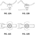
Figures 12A-12D show a second allowed movement enabled by the thumb fixing mechanism of the invention. -
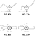
Figures 13A-13D show a third allowed movement enabled by the thumb fixing mechanism of the invention. -
Figures 14A-14B show a fourth allowed movement enabled by the thumb fixing mechanism of the invention. - In this text, the term "comprises" and its derivations (such as "comprising", etc.) should not be understood in an excluding sense, that is, these terms should not be interpreted as excluding the possibility that what is described and defined may include further elements, steps, etc.
- In the context of the present invention, the term "approximately" and terms of its family (such as "approximate", etc.) should be understood as indicating values very near to those which accompany the aforementioned term. That is to say, a deviation within reasonable limits from an exact value should be accepted, because a skilled person in the art will understand that such a deviation from the values indicated is inevitable due to measurement inaccuracies, etc. The same applies to the terms "about" and "around" and "substantially".
- The following description is not to be taken in a limiting sense but is given solely for the purpose of describing the broad principles of the invention. Next embodiments of the invention will be described by way of example, with reference to the above-mentioned drawings showing apparatuses and results according to the invention.
-
Figures 1A-1C and2 show respective views of an exemplary portablehand rehabilitation device 30 comprising athumb rehabilitation assembly 20. Thedevice 30 comprises athumb fixing mechanism 40 according to an embodiment of the invention. Thethumb fixing mechanism 40 is not limited to this exemplaryhand rehabilitation device 30. What is more, thethumb fixing mechanism 40 is not limited to this exemplarythumb rehabilitation assembly 20. On the contrary, thethumb fixing mechanism 40 of this invention is to be used in any hand rehabilitation device requiring adjustment of a part or group of parts dedicated to the rehabilitation of a thumb, such as thethumb rehabilitation assembly 20 illustrated infigures 1A-1C and2 .Figures 1B and 1C explain how therehabilitation assembly 20 is attached to thelocking mechanism 40. The two rod ends5x 5y (described later and shown in detail infigure 3A ) are press-fit to corresponding matchingreceptacles 21 22 on therehabilitation assembly 20. - The exemplary
hand rehabilitation device 30 is configured to be grasped by the hand to be trained or rehabilitated, in such a way that the palm, fingers and thumb (inner part of the hand) surround the graspeddevice 30. When grasping the hand-helddevice 30 by an impaired hand, the inner part of the fingers and thumb are disposed on several supports or "finger rests" (for example the thumb is supported on rest or support 21). The remaining supports for the fingers (index, middle, ring and little fingers) are not explained because they are not relevant for the present invention. In this example, thethumb support 21 is attached to astructure 20 which holds the transmission mechanism for thatsupport 21. In use of thedevice 30, the supports or rests for the thumb and fingers are moved, actuated by one or more motors, provoking the flexion/extension of the thumb and fingers supported on the corresponding supports or rests. As can be observed,device 30 permits independent rehabilitation of the thumb by means ofsupport 21 and corresponding transmission mechanism. Rehabilitation of the index, middle ring and little fingers is out of the scope of the present invention. Theexemplary device 30 permits passive rotation of finger (and thumb) supports for self-alignment with hands of varying sizes. -
Figure 3A shows a break-up of thumb fixing mechanism 40 (or thumb lock mechanism) according to a possible embodiment of the invention.Figure 3B shows the mechanism once assembled. Themechanism 40 serves at adjusting the initial position of the thumb prior to starting a rehabilitation session. The thumb size may vary from person to person. Themechanism 40 works both of a right hand thumb and of a left hand thumb. Themechanism 40 provides a joint 8 that allows the adjustment of four independent positions of the bent rod (referred to as 5A, 5B, 5x, 5y) where the thumb rehabilitation assembly is attached, thus providing 4 degrees of freedom (DOF). This way, the thumb assembly can be adjusted in 4 different angles. The 4 DOF can all be locked/unlocked with a single movement or click of the mechanism. -
Mechanism 40 is based on a joint 8 composed of upper and lower halves defining two cylindrical canals in between, in such a way that guiding means, such as a curved rail or rod, can move (slide) along the canals, between the two halves of the joint, or be clamped (fixed) in place there between. The shape of the curved sliding rail is such that it allows anthropometric positioning of the thumb with respect to a large range of human hand sizes. -
Mechanism 40 comprises several parts. It comprises a quick fixing/releasingmechanism 10. The fixing/releasing 10 has an elongated member, such as a bolt, stick orskewer 1. In a particular embodiment, one of the ends of theelongated member 1 forms twoprotrusions 101 102 that exceed the section of the elongated member. Theprotrusions 101 102 are preferably perpendicular to theelongated member 1 and aligned with each other, that is to say, forming a 180º angle with respect to each other. In other words,member 1 has a "T" shape or hammer shape. The fixing/releasing 10 may comprise apart 12 having a thru hole along which theelongated member 1 can slide with clearance. So,part 12 enters theelongated member 1 through its end not ended in twoprotrusions 101 102. The fixing/releasing 10 of this embodiment also comprises anarm 11 having an end terminated in a cam or rotating mechanism. Theelongated member 1 is connected, preferably by means of theprotrusions 101 102, to this cam or rotating mechanism. This cam-like mechanism is implemented in this embodiment by twomembers 111 112 defining respective holes which are aligned with each other, defining a rotation axis. The twomembers 111 112 form a single part with thearm 11. Since thearm 11 works as a lever, both terms "arm" and "lever" are used equally to refer toelement 11. The quick fixing/releasingmechanism 10 has two positions actioned byarm 11 that will be explained later in this text.Protrusions 101 102 of theelongated member 1 couple with corresponding holes in the cam orrotating mechanism 111 112. The cam-like mechanism 111 112 oflever 11 makes theelongated member 1 move up-down depending on the angle of thelever 11.Part 12 has a surface (labeled with dotted arrows infigure 9D ) that is in contact with thecam mechanism 111 112 inlever 11. -
Mechanism 40 also comprises a part orsupport 2.Part 2 is a fixed part acting as a reference for all other parts, which are connected topart 2. Besides,part 2 represents the geometry required at the hand rehabilitation device to which the thumb lock is connected to, that is to say,part 2 needs to align with a particular hand rehabilitation device to which this thumb lock may be connected to. In other words, the geometry ofpart 2, specially its outer shape, may vary in alternative embodiments, depending on the robot to which the thumb lock mechanism is connected to. Part orsupport 2 is configured to be inserted along theelongated member 1, preferably oncepart 12 has been inserted.Part 2 may take any shape, provided it has a thru hole that enablespart 2 to be inserted along theelongated member 1, as shown for example infigures 3A and3B . In a particular embodiment,part 2 could be fixed topart 12. So,part 12 is coupled topart 2. In particular, the upper surface ofpart 12 is in contact with the lower surface ofpart 2. As already mentioned,part 2 plays the role of being a reference for the other parts. In particular, the other parts involved in the locking mechanism (parts part 2 as mechanism is built by sliding those parts alongelongated member 1.Part 2 is preferably an independent part with respect to the elongated member 1 (andmechanism 10, if any). Alternatively, it could be, together withpart 12, an integral part of the lower portion of theelongated member 1. In use of the mechanism,part 2 does not move.Figure 5 shows one view ofpart 2 according to the embodiment illustrated infigures 3A-3B . The thru hole required for slidingpart 2 along theelongated member 1 is shown. The particular implementation ofpart 2 illustrated infigure 5 has two straight parallel sides and two curved sides. However, this shape may vary, depending on the robot to which to thumb lock mechanism is connected. -
Mechanism 40 also has a joint 8 that, when assembled, takes the form of a housing. It is made of three pieces orparts 3 4 6. Joint orhousing 8 comprises a substantiallysemispherical part 3.Part 3 defines a spherical cap shape receptacle. It also has a smaller normal hole to let theelongated member 1 thru.Figure 6 shows two views ofpart 3 according to the embodiment illustrated infigures 3A-3B .Part 3 has a throughhole 3C in its central position that permits the insertion ofpart 3 along theelongated member 1. Therefore, the throughhole 3C ofpart 3 has substantially the same section as the diameter of theelongated member 1. In use of themechanism 40, whenpart 3 is inserted along theelongated member 1, theelongated member 1 receives the convex surface ofpart 3.Part 3 is then placed onpart 2, which has previously been placed on part se 12. In order for a correct adjustment ofpart 3 on top ofpart 2,part 3 should be manufactured so that there is no interference in order to reduce friction during readjustment. Once the mechanism is in the "locked" configuration, thenparts Fig 9A (unlocked position) and inFig. 9C (locked position)). -
Housing 8 also comprises two swivels orrotating joints 4 6.Figures 7 and 8 respectively show views ofswivels figures 3A-3B . Swivels orrotating joints 4 6 are of spherical cap shape.Swivels 4 6 also have a throughhole 4Celongated member 1.Swivels 4 6 are substantially complementary, in such a way that when they are coupled to each other in their non-convex side, they form a substantially closed part perforated by a through hole. The hollow has truncated-cone shape.Swivels 4 6 are solid parts on which two substantiallyparallel 6Acanals 4A 4BPart 4 has a conical hole.Part 6 has a "spherical cap" hole. Therefore there is alower swivel 4 and anupper swivel 6. The through hole of eachswivel 4 6 has a larger section than the diameter of theelongated member 1, in order to receive anut 7.Nut 7 is substantially semispherical.Nut 7 is a lockable adjusting nut. As shown infigure 3B , when the threeparts 3 4 6 forminghousing 8 are inserted alongelongated member 1 andnut 7 is also inserted on top ofhousing 8, the free end ofelongated member 1 slightly shows up at the upper side of the assembly, surrounded bynut 7. In use of the mechanism,nut 7 is screwed toelongated member 1 and remains always at the same position. - Finally,
mechanism 40 also has guiding means 5 preferably formed by a curved rail or rod. Guiding means 5 forms twosections 5Aparallel 6Acanals 4A 4Bswivels 4 6. Guiding means 5 is preferably formed by a single rod bended on one end, thus providing two substantiallyparallel sections 5Asections 5Amechanism 40, guiding means 5 is designed to be inserted between swivels orrotating joints 4 6, as clearly appreciated for example in the section view offigure 4A . In particular, the twosections 5Acanals swivels 4 6.Figure 7 shows two views of a particular embodiment ofswivel 4, in detail.Figure 8 shows two views of a particular embodiment ofswivel 6, in detail.Swivel 4 has two substantiallyparallel canals 4ASwivel 6 has two substantiallyparallel canals 6Acanals 4Aswivel 4. Thus, when assembling themechanism 40, when the twosections 5Acanals 4Alower swivel 4 and theupper swivel 6 is then disposed on thelower swivel 4, making thecanals 6Aupper swivel 6 match thecanals 4Alower swivel 4, the twosections 5Aswivels 4 6. Depending on the position (unlocked or locked) of the quick fixing/releasingmechanism 10, guiding means 5 can freely slide along those canals (unlocked position) or they are caught (captured) between the twoswivels 4 6 (locked position). As already explained, guiding means 5 can be one single piece or two pieces. In any case, guiding means 5 has at least twofree ends 5x 5y designed to adapt to the thumb rehabilitation assembly to be fixed or adjusted, as explained with reference tofigures 1B and 1C . - Turning back to the substantially spherical cap shape part (receptacle) 3, shown in detail in
figure 6 , it can be observed thatpart 3 also has twocanals 3Acanals 4Alower swivel 4, in such a way that when themechanism 40 is assembled,part 3 guides the twosections 5Acanal 3Acanal 3Bfigure 3B , do not interfere with the through hole that also goes through the joint 8 from an upper side to a lower side of the joint, configured to receive thebolt 1, as seen for example infigure 3B . -
Figure 4A shows a section view of the break-up of thethumb fixing mechanism 40 offigures 3A and3B , whilefigure 4B shows a section view of themechanism 40 once assembled. -
Figures 9A and 9B show a comparison between "open" (unlocked) (figure 9A ) and "closed" (locked) (figure 9B ) positions of thethumb fixing mechanism 40 offigures 3A and3B . The quick fixing/releasingmechanism 10 has two positions actioned by arm orlever 11. The two positions are shown infigures 9A and 9B and imply a rotation of thelever 11 of around 90º. In a first position (loose position), which in a particular embodiment may occur (but not in a limitative way) whenarm 11 is aligned with the longitudinal axis ofelongated member 1, the fixing/releasing mechanism 10 (and therefore the thumb fixing mechanism 40) is in open (unlocked) position (figure 9A ). In this position, the contact surfaces I, II, III, IV and V between different parts of the mechanism are loose, that is to say, there is a gap in those surfaces between the affected parts. A second position (locked position) occurs when all contact surfaces I, II, III, IV and V are tight, meaning that there is no gap in those surfaces between the affected parts, because friction in the contact surfaces locks all parts in place. It is remarked that with the quick fixing/releasingmechanism 10,nut 7 is always (both in locked and unlocked position) in the same position relative to the cam-like mechanism 111 112 oflever 11. In a particular embodiment, which should not be taken in a limiting way, this tight position is achieved after movinglever 11, for example by rotatinglever 11 about the rotation axis defined by holes in the cam-like mechanism 111 112. The fixing/releasing mechanism 10 (and therefore the thumb fixing mechanism 40) is in locked position (figure 9B ). The quick fixing/releasing mechanism 10 (formed byelongated member 1,lever 11 and part 12) can be replaced by an alternative fixing/release mechanism 110 as illustrated infigures 10A-10C , as discussed later. Thismechanism 110 is composed of a screw. - The
mechanism 40 is locked (figure 9B ) when surfaces I, II, III, IV and V infigure 9A are in contact due to the compression force applied by theelongated member 1 and thenut 7.Lever 11 pushes elongatedmember 1 and, as a consequence,nut 7 compresses everything in between (that is to say,parts lever 11 pulls elongatedmember 1 downward and this, in its upper position, is used to tighten the entire assembly while nut remains untouched. In a less preferred embodiment,nut 7 may be tightened instead of using the lever (11, 12), which would remain untouched. Themechanism 40 is open (unlocked) (figure 9A ) when the contact between surfaces I, II, III, IV and V infigure 9A is released. This contact between surfaces is released preferably by releasing the compression force applied fromelongated member 1 andnut 7. Themechanism 40 has 5 contact surfaces (referred to with Roman numerals infigures 9A and9C ) that are in substantial close contact whennut 7 is locked (preferably by manipulating lever 11) and are released whennut 7 is released (preferably by manipulating lever 11). This means that with a single part (nut 7), themechanism 40 is capable of simultaneously locking or unlocking the 4 degrees of freedom of themechanism 40. The five surfaces I, II, III, IV, V are involved in the achievement of these 4 DOF. In other words, releasinglever 11 has the effect of releasing the surface friction between all parts.Figure 9D shows another view of the locked mechanism. It can be observed thatpart 12 has a surface (labeled with dotted arrows infigure 9D ) that is in contact with the cam mechanism 13 inlever 11. - In other words, prior to the use by a user of a thumb rehabilitating device having a
thumb fixing mechanism 40, themechanism 40 being connected to the thumb rehabilitating structure by means of the two ends5x 5y of guidingmeans 5, the user (or a therapist, for example), having themechanism 40 in open position (figure 9A ), adjusts or selects 4 possible positions of the orientation of the guiding means 5. Once the four positions are selected but not fixed, by a single movement ofarm 11 themechanism 40 is locked (figure 9B ). -
Figure 9C shows a detail of the "open" position (released or unlocked mechanism) of thethumb fixing mechanism 40. The 5 contact surfaces involved in achieving the 4 DOF are labelled: Roman I refers to the contact surface between part (support) 2 and part (receptacle) 3. Roman II refers to the contact surface betweenreceptacle 3 and lower swivel orrotating joint 4. Roman III refers to the contact surface between the lower swivel or rotating joint 4 and upper swivel orrotating joint 6. Roman IV refers to the contact surface between upper swivel or rotating joint 6 andnut 7. Roman V refers to the contact surface betweenpart 12 andpart 2. -
Figures 10A-10C show an alternative embodiment, in which the quick fixing/releasingmechanism 10 has been replaced by another fixing/releasingmechanism 110 composed of conventional screw 110 (in particular, M5 screw). Thescrew 110 comprises an elongated member 1'. In the former embodiment (lever 11,elongated member 1 and part 12) the compression, thanks to which the contact between surfaces is tight- is achieved by manipulatinglever 11. However, in thisembodiment using screw 110, the compression is achieved by fixing (turning) thescrew 110, which is usually done with an Allen key. It is remarked that, in this embodiment,nut 7 is loose with respect to thescrew 110 in the unlocked position, andnut 7 is tight with respect to thescrew 110 in the locked position. - In any of the described embodiments, the four allowed movements that permit fixing the thumb with 4 DOF are:
- (1) A first movement is the turn of joint 8 and therefore of sliding guiding means 5. This first movement is represented in
figures 11A-11D. Figures 11A and 11C show respective side and top views of a first position of the mechanism.Figures 11B and 11D show respective side and top views of a turned position with respect to the first one, after performing this first movement. - (2) A second movement is the tilting of
parts part 3.Part 5 is rigidly clamped byparts Parts part 4 moves, thenpart 6 also moves equally. Slidingrods 5 move together withparts parts figures 12A-12D. Figures 12A and 12C show respective side and top views of a first position of the mechanism.Figures 12B and 12D show respective side and top views of a second position with respect to the first one, in whichrod 5 has slid backwards. - (3) A third movement is a displacement of the sliding guiding means 5 along the canals defined by the two
parts 4 6. This third movement is represented infigures 13A-13D. Figures 13A and 13C show respective side and top views of a first position of the mechanism.Figures 13B and 13D show respective side and top views of a second position with respect to the first one, in whichrod 5 has swang. - (4) A fourth movement is the basculation/tilting/rotation of
parts part 2, but the direction of the rotation axis is different than the one in movement (2).Part 5 is rigidly clamped byparts Part 3 does not move.Figures 14A and 14B show front views of the mechanism.Figure 14B shows a swing ofpart 3 with respect tofigure 14A . - In
figures 9A-9C all the labeled surfaces are important and are involved in all different positions. This implies that the mechanism permits to adjust 4 degrees of freedom and only 1 lock is needed to block them all. - In sum, when a user (person having an impaired hand) is going to start using a hand rehabilitation device having a thumb rehabilitation assembly, he/she first adjusts the thumb rehabilitation assembly by means of the thumb fixing mechanism that has been described in this text. This is done as follows: first,
arm 11 is released (by manipulating and substantially aligning it with respect to the bolt, as shown infigure 9A ). Then, the four possible movements (4 DOF) are manipulated and selected according to the size of the thumb and hand of the user. Once the four independent positions are selected,arm 11 is manipulated again, and with a single lock the 4 DOF are fixed (figure 9B ). Instead of the assembly formed byarm 11,elongated member 1 andpart 12,screw 110 can be used. - In conclusion, a simple thumb adjustment mechanism has been provided. It permits the adjustment of the thumb in four independent positions, thus providing 4 degrees of freedom (DOF), with a single click (same click for the simultaneous fixation of the four DOF). Thus, anthropometric positioning of the thumb with respect to a large range of human hand sizes is allowed.
- On the other hand, the invention is obviously not limited to the specific embodiment(s) described herein, but also encompasses any variations that may be considered by any person skilled in the art (for example, as regards the choice of materials, dimensions, components, configuration, etc.), within the general scope of the invention as defined in the claims.
Claims (7)
- A hand rehabilitation device comprising a thumb rehabilitation assembly (20) and a thumb fixing mechanism (40) coupled to said thumb rehabilitation assembly (20) for the anthropometric positioning of a thumb of a user,
the device being characterized in that the thumb fixing mechanism (40) comprises:- a fixing/releasing mechanism (10, 110) comprising an elongated member (1, 1');- a first part (2) comprising a through hole for sliding said part (2) along said elongated member (1, 1');- a joint (8) comprising two parallel hollow canals (3A, 4A, 6A; 3B, 4B, 6B) that go through the joint (8) from a first side to a second side thereof, opposite to the first side, said joint (8) comprising a through hole (3C, 4C, 6C) configured to mount the joint (8) concentrically along said elongated member (1, 1') until the joint (8) is supported on said first part (2);- guiding means (5) comprising two sections (5A, 5B) inserted along respective said two parallel hollow canals (3A, 4A, 6A; 3B, 4B, 6B), said two sections (5A, 5B) being capable of sliding along said canals (3A, 4A, 6A; 3B, 4B, 6B), wherein one end (5x, 5y) of each of said two sections (5A, 5B) are connected to said thumb rehabilitation assembly (20);- a nut (7) configured to be concentrically mounted on said joint (8) along said elongated member (1, 1');wherein the fixing/releasing mechanism (10, 110) is configured to manually switch from a first position to a second position and vice versa: a first unlocked position in which the joint (8) and the guiding means (5) are free to perform a plurality of independent movements in different directions for adjusting said thumb rehabilitation assembly (20); and a second locked position in which the movement of said joint (8) and guiding means (5) is blocked, thus fixing the thumb rehabilitation assembly (20) in the position selected after performing said plurality of independent movements. - The device of claim 1, wherein said fixing/releasing mechanism (10) of said thumb fixing mechanism (40) further comprises a lever (11) having an end terminated in a cam-like mechanism (111, 112) and a part (12), wherein one end of said elongated member (1) is coupled to said cam-like mechanism (111, 112), said part (12) being configured to slide along said elongated member (1) until it contacts said cam-like mechanism (111, 112), said two positions of the fixing/releasing mechanism (10) being actioned by said lever (11).
- The device of claim 2, wherein said end of said elongated member (1) coupled to said cam-like mechanism (111, 112) comprises two protrusions (101, 102) that exceed the section of the elongated member (1) and said cam-like mechanism (111, 112) comprises respective holes aligned with each other, each of said two protrusions (101, 102) being configured to couple with a corresponding hole.
- The device of claim 1, wherein said fixing/releasing mechanism (110) of said thumb fixing mechanism (40) is formed by a screw (110), said screw comprising said elongated member (1').
- The device of any preceding claims, wherein the joint (8) of said thumb fixing mechanism (40) comprises:- a second part (3) having a through hole (3C), the second part (3) being configured to be inserted along said elongated member (1, 1'), that receives a convex surface of said part (3) until it is supported on said first part (2); and- first and second swivels (4, 6) of spherical cap shape, having respective through holes (4C, 6C), said first and second swivels (4, 6) being configured to couple with each other at their respective non-convex sides, and configured to be inserted along said elongated member (1, 1') through said through holes (4C, 6C) until they are supported on said second part (3).
- The device of claim 5, wherein said plurality of independent movements for adjusting said thumb rehabilitation assembly are performed thanks to five contact surfaces that are released in said first unlocked position of the fixing/release mechanism (10, 110), said contact surfaces being: a first contact surface between said first part (2) and said second part (3); a second contact surface between said second part (3) and said lower swivel (4); a third contact surface between said lower swivel (4) and said upper swivel (6); a fourth contact surface between said upper swivel (6) and said nut (7); and a fifth surface between said first part (2) and said fixing/releasing mechanism (10, 110).
- The device of any preceding claim, wherein the guiding means (5) of said thumb fixing mechanism (40) comprises two curved sections (5A, 5B), thus allowing anthropometric positioning of the thumb.
Priority Applications (2)
| Application Number | Priority Date | Filing Date | Title |
|---|---|---|---|
| EP16382037.6A EP3199137A1 (en) | 2016-01-29 | 2016-01-29 | Hand rehabilitation device with fixing mechanism |
| PCT/EP2017/051836 WO2017129786A1 (en) | 2016-01-29 | 2017-01-27 | Hand rehabilitation device with fixing mechanism |
Applications Claiming Priority (1)
| Application Number | Priority Date | Filing Date | Title |
|---|---|---|---|
| EP16382037.6A EP3199137A1 (en) | 2016-01-29 | 2016-01-29 | Hand rehabilitation device with fixing mechanism |
Publications (1)
| Publication Number | Publication Date |
|---|---|
| EP3199137A1 true EP3199137A1 (en) | 2017-08-02 |
Family
ID=55272418
Family Applications (1)
| Application Number | Title | Priority Date | Filing Date |
|---|---|---|---|
| EP16382037.6A Withdrawn EP3199137A1 (en) | 2016-01-29 | 2016-01-29 | Hand rehabilitation device with fixing mechanism |
Country Status (2)
| Country | Link |
|---|---|
| EP (1) | EP3199137A1 (en) |
| WO (1) | WO2017129786A1 (en) |
Citations (10)
| Publication number | Priority date | Publication date | Assignee | Title |
|---|---|---|---|---|
| DE293622C (en) * | ||||
| FR1261410A (en) * | 1960-04-08 | 1961-05-19 | Device for finger rehabilitation | |
| US5516249A (en) | 1994-05-10 | 1996-05-14 | Technical Research Associates, Inc. | Exoskeleton with kinesthetic feedback and robotic control |
| US20090326428A1 (en) * | 2002-02-25 | 2009-12-31 | Saebo, Inc. | Dynamic hand splint |
| WO2010140984A1 (en) | 2009-06-03 | 2010-12-09 | National University Of Singapore | Finger function rehabilitation device |
| US20110070021A1 (en) * | 2009-09-24 | 2011-03-24 | Michael Lin | Fixing device for an extension tube of an exercise device |
| CN201798881U (en) * | 2010-09-10 | 2011-04-20 | 苏芳庆 | A finger rehabilitation structure |
| WO2013036925A2 (en) * | 2011-09-08 | 2013-03-14 | President And Fellows Of Harvard College | Isolated orthosis for thumb actuation |
| US20130261514A1 (en) * | 2012-03-30 | 2013-10-03 | The Hong Kong Polytechnic University | Wearable power assistive device for hand rehabilitation |
| US8574178B2 (en) | 2009-05-26 | 2013-11-05 | The Hong Kong Polytechnic University | Wearable power assistive device for helping a user to move their hand |
-
2016
- 2016-01-29 EP EP16382037.6A patent/EP3199137A1/en not_active Withdrawn
-
2017
- 2017-01-27 WO PCT/EP2017/051836 patent/WO2017129786A1/en not_active Ceased
Patent Citations (10)
| Publication number | Priority date | Publication date | Assignee | Title |
|---|---|---|---|---|
| DE293622C (en) * | ||||
| FR1261410A (en) * | 1960-04-08 | 1961-05-19 | Device for finger rehabilitation | |
| US5516249A (en) | 1994-05-10 | 1996-05-14 | Technical Research Associates, Inc. | Exoskeleton with kinesthetic feedback and robotic control |
| US20090326428A1 (en) * | 2002-02-25 | 2009-12-31 | Saebo, Inc. | Dynamic hand splint |
| US8574178B2 (en) | 2009-05-26 | 2013-11-05 | The Hong Kong Polytechnic University | Wearable power assistive device for helping a user to move their hand |
| WO2010140984A1 (en) | 2009-06-03 | 2010-12-09 | National University Of Singapore | Finger function rehabilitation device |
| US20110070021A1 (en) * | 2009-09-24 | 2011-03-24 | Michael Lin | Fixing device for an extension tube of an exercise device |
| CN201798881U (en) * | 2010-09-10 | 2011-04-20 | 苏芳庆 | A finger rehabilitation structure |
| WO2013036925A2 (en) * | 2011-09-08 | 2013-03-14 | President And Fellows Of Harvard College | Isolated orthosis for thumb actuation |
| US20130261514A1 (en) * | 2012-03-30 | 2013-10-03 | The Hong Kong Polytechnic University | Wearable power assistive device for hand rehabilitation |
Non-Patent Citations (2)
| Title |
|---|
| KREBS HI; VOLPE BT; WILLIAMS D ET AL.: "Robot-aided neurorehabilitation: a robot for wrist rehabilitation", IEEE TRANSNEURAL SYST REHABIL ENG, vol. 15, 2007, pages 327 - 335, XP011348057, DOI: doi:10.1109/TNSRE.2007.903899 |
| TAKAHASHI CD; DER-YEGHIAIAN L; LE VH; CRAMER SC: "A robotic device for hand motor therapy after stroke", INTERNATIONAL CONFERENCE ON REHABILITATION ROBOTICS, ICORR PROCEEDINGS, 28 June 2005 (2005-06-28) |
Also Published As
| Publication number | Publication date |
|---|---|
| WO2017129786A1 (en) | 2017-08-03 |
Similar Documents
| Publication | Publication Date | Title |
|---|---|---|
| CN110180139B (en) | Spring-grip dumb-bell | |
| US7699848B2 (en) | Multipin clamp and rod attachment | |
| US9827011B2 (en) | Polyaxial pivot housing for external fixation system | |
| US8366710B2 (en) | External fixator | |
| KR20190059568A (en) | Upper limb rehabilitation robot connectable with end-effector type robot | |
| US11224553B2 (en) | Hand rehabilitation device | |
| KR20180012259A (en) | Attachment for remote access tool | |
| US20050246034A1 (en) | Implantable mechanical device with adjustable geometry | |
| JP6474628B2 (en) | Catheter clip | |
| WO2004062514A1 (en) | External fixation apparatus | |
| US20130276844A1 (en) | Handle Assembly With Multi-Axial Adjustment | |
| EP4042982B1 (en) | Prosthetic thumb device | |
| KR102194331B1 (en) | Chest expander | |
| CN113613613B (en) | Ball joint fixation bracket | |
| WO2017129786A1 (en) | Hand rehabilitation device with fixing mechanism | |
| JP2020535876A (en) | Adjustable length articulated stabilizer arm | |
| DE102018009174A1 (en) | Hand exoskeleton | |
| US20090156368A1 (en) | Exercise device and its arm rest | |
| CN107928987A (en) | The holding mechanism of wrist joint device for healing and training | |
| KR20040108123A (en) | Stick | |
| US20250319354A1 (en) | Hand exercise rehabilitation system and method | |
| US5820521A (en) | Hand held exerciser | |
| WO2024130953A1 (en) | Multifunctional hand gripper | |
| KR20150108666A (en) | Adjustable weight dumbbells | |
| US20250339329A1 (en) | Medical hand and forearm fixing device |
Legal Events
| Date | Code | Title | Description |
|---|---|---|---|
| PUAI | Public reference made under article 153(3) epc to a published international application that has entered the european phase |
Free format text: ORIGINAL CODE: 0009012 |
|
| AK | Designated contracting states |
Kind code of ref document: A1 Designated state(s): AL AT BE BG CH CY CZ DE DK EE ES FI FR GB GR HR HU IE IS IT LI LT LU LV MC MK MT NL NO PL PT RO RS SE SI SK SM TR |
|
| AX | Request for extension of the european patent |
Extension state: BA ME |
|
| STAA | Information on the status of an ep patent application or granted ep patent |
Free format text: STATUS: THE APPLICATION IS DEEMED TO BE WITHDRAWN |
|
| 18D | Application deemed to be withdrawn |
Effective date: 20180203 |