EP3199136A1 - Hand rehabilitation device - Google Patents
Hand rehabilitation device Download PDFInfo
- Publication number
- EP3199136A1 EP3199136A1 EP16382036.8A EP16382036A EP3199136A1 EP 3199136 A1 EP3199136 A1 EP 3199136A1 EP 16382036 A EP16382036 A EP 16382036A EP 3199136 A1 EP3199136 A1 EP 3199136A1
- Authority
- EP
- European Patent Office
- Prior art keywords
- support
- fingers
- hand
- flexion
- transmission mechanism
- Prior art date
- Legal status (The legal status is an assumption and is not a legal conclusion. Google has not performed a legal analysis and makes no representation as to the accuracy of the status listed.)
- Granted
Links
Images













Classifications
-
- A—HUMAN NECESSITIES
- A61—MEDICAL OR VETERINARY SCIENCE; HYGIENE
- A61H—PHYSICAL THERAPY APPARATUS, e.g. DEVICES FOR LOCATING OR STIMULATING REFLEX POINTS IN THE BODY; ARTIFICIAL RESPIRATION; MASSAGE; BATHING DEVICES FOR SPECIAL THERAPEUTIC OR HYGIENIC PURPOSES OR SPECIFIC PARTS OF THE BODY
- A61H1/00—Apparatus for passive exercising; Vibrating apparatus; Chiropractic devices, e.g. body impacting devices, external devices for briefly extending or aligning unbroken bones
- A61H1/02—Stretching or bending or torsioning apparatus for exercising
- A61H1/0274—Stretching or bending or torsioning apparatus for exercising for the upper limbs
- A61H1/0285—Hand
- A61H1/0288—Fingers
-
- A—HUMAN NECESSITIES
- A61—MEDICAL OR VETERINARY SCIENCE; HYGIENE
- A61H—PHYSICAL THERAPY APPARATUS, e.g. DEVICES FOR LOCATING OR STIMULATING REFLEX POINTS IN THE BODY; ARTIFICIAL RESPIRATION; MASSAGE; BATHING DEVICES FOR SPECIAL THERAPEUTIC OR HYGIENIC PURPOSES OR SPECIFIC PARTS OF THE BODY
- A61H2201/00—Characteristics of apparatus not provided for in the preceding codes
- A61H2201/01—Constructive details
- A61H2201/0119—Support for the device
- A61H2201/0153—Support for the device hand-held
-
- A—HUMAN NECESSITIES
- A61—MEDICAL OR VETERINARY SCIENCE; HYGIENE
- A61H—PHYSICAL THERAPY APPARATUS, e.g. DEVICES FOR LOCATING OR STIMULATING REFLEX POINTS IN THE BODY; ARTIFICIAL RESPIRATION; MASSAGE; BATHING DEVICES FOR SPECIAL THERAPEUTIC OR HYGIENIC PURPOSES OR SPECIFIC PARTS OF THE BODY
- A61H2201/00—Characteristics of apparatus not provided for in the preceding codes
- A61H2201/01—Constructive details
- A61H2201/0157—Constructive details portable
-
- A—HUMAN NECESSITIES
- A61—MEDICAL OR VETERINARY SCIENCE; HYGIENE
- A61H—PHYSICAL THERAPY APPARATUS, e.g. DEVICES FOR LOCATING OR STIMULATING REFLEX POINTS IN THE BODY; ARTIFICIAL RESPIRATION; MASSAGE; BATHING DEVICES FOR SPECIAL THERAPEUTIC OR HYGIENIC PURPOSES OR SPECIFIC PARTS OF THE BODY
- A61H2201/00—Characteristics of apparatus not provided for in the preceding codes
- A61H2201/12—Driving means
- A61H2201/1207—Driving means with electric or magnetic drive
- A61H2201/1215—Rotary drive
-
- A—HUMAN NECESSITIES
- A61—MEDICAL OR VETERINARY SCIENCE; HYGIENE
- A61H—PHYSICAL THERAPY APPARATUS, e.g. DEVICES FOR LOCATING OR STIMULATING REFLEX POINTS IN THE BODY; ARTIFICIAL RESPIRATION; MASSAGE; BATHING DEVICES FOR SPECIAL THERAPEUTIC OR HYGIENIC PURPOSES OR SPECIFIC PARTS OF THE BODY
- A61H2201/00—Characteristics of apparatus not provided for in the preceding codes
- A61H2201/12—Driving means
- A61H2201/1238—Driving means with hydraulic or pneumatic drive
-
- A—HUMAN NECESSITIES
- A61—MEDICAL OR VETERINARY SCIENCE; HYGIENE
- A61H—PHYSICAL THERAPY APPARATUS, e.g. DEVICES FOR LOCATING OR STIMULATING REFLEX POINTS IN THE BODY; ARTIFICIAL RESPIRATION; MASSAGE; BATHING DEVICES FOR SPECIAL THERAPEUTIC OR HYGIENIC PURPOSES OR SPECIFIC PARTS OF THE BODY
- A61H2201/00—Characteristics of apparatus not provided for in the preceding codes
- A61H2201/14—Special force transmission means, i.e. between the driving means and the interface with the user
-
- A—HUMAN NECESSITIES
- A61—MEDICAL OR VETERINARY SCIENCE; HYGIENE
- A61H—PHYSICAL THERAPY APPARATUS, e.g. DEVICES FOR LOCATING OR STIMULATING REFLEX POINTS IN THE BODY; ARTIFICIAL RESPIRATION; MASSAGE; BATHING DEVICES FOR SPECIAL THERAPEUTIC OR HYGIENIC PURPOSES OR SPECIFIC PARTS OF THE BODY
- A61H2201/00—Characteristics of apparatus not provided for in the preceding codes
- A61H2201/16—Physical interface with patient
- A61H2201/1602—Physical interface with patient kind of interface, e.g. head rest, knee support or lumbar support
- A61H2201/1635—Hand or arm, e.g. handle
-
- A—HUMAN NECESSITIES
- A61—MEDICAL OR VETERINARY SCIENCE; HYGIENE
- A61H—PHYSICAL THERAPY APPARATUS, e.g. DEVICES FOR LOCATING OR STIMULATING REFLEX POINTS IN THE BODY; ARTIFICIAL RESPIRATION; MASSAGE; BATHING DEVICES FOR SPECIAL THERAPEUTIC OR HYGIENIC PURPOSES OR SPECIFIC PARTS OF THE BODY
- A61H2201/00—Characteristics of apparatus not provided for in the preceding codes
- A61H2201/16—Physical interface with patient
- A61H2201/1602—Physical interface with patient kind of interface, e.g. head rest, knee support or lumbar support
- A61H2201/165—Wearable interfaces
-
- A—HUMAN NECESSITIES
- A61—MEDICAL OR VETERINARY SCIENCE; HYGIENE
- A61H—PHYSICAL THERAPY APPARATUS, e.g. DEVICES FOR LOCATING OR STIMULATING REFLEX POINTS IN THE BODY; ARTIFICIAL RESPIRATION; MASSAGE; BATHING DEVICES FOR SPECIAL THERAPEUTIC OR HYGIENIC PURPOSES OR SPECIFIC PARTS OF THE BODY
- A61H2201/00—Characteristics of apparatus not provided for in the preceding codes
- A61H2201/16—Physical interface with patient
- A61H2201/1657—Movement of interface, i.e. force application means
- A61H2201/1676—Pivoting
Definitions
- the present invention relates to the field of devices for rehabilitation of impaired limbs and, in particular, to devices for rehabilitation of impaired hands and fingers.
- Finger function can be lost or damaged as a result of neurological injuries, such as stroke, spinal cord injuries, traumatic brain injuries or Parkinson disease.
- stroke may cause paralysis of one side of the body.
- Examples of damaged finger functions are failure to extend fingers, poor finger coordination, loss of finger independence, poor grasping or manipulation ability and inability to control constant grip force. Since the brain has certain capacity to reorganize the damaged neural connections, a partial (or even complete) recovery of the damaged functions is possible.
- exoskeletons are robotic skeletons that externally embrace a limb or part of the body.
- United States patent US-5516249-A describes an exoskeletal control apparatus based on a glove framework into which a hand can be inserted.
- a similar system is disclosed in United States patent US-8574178-B2 .
- This type of devices is complex because they have a lot of moving parts, which results in expensive maintenance. Besides, they require long time to fit a patient's hand to the device.
- finger rehabilitation systems such as the one disclosed in International patent application WO-2010/140984-A1 , which comprises a support on which an impaired arm is fixed and five sub-systems, each of them comprising a finger fixation (strap) and a clutch system.
- Each finger strap is actuated by means of a cable (guided through a pulley) pulling in one direction and a bow spring in the other.
- this system is hardly portable due to its non-compactness.
- a force is applied on each finger fixation and is therefore concentrated on a finger joint, therefore causing a potential damage on the joint and not optimizing the finger function rehabilitation.
- finger flexion is provided exclusively by the bow spring component, not the motor, which makes the applied control to the fingers harder to control.
- the different functions of the different fingers are optimized with the proposed device, because it permits independent rehabilitation (functional flexion/extension) of thumb and index finger, involved in most types of grasping.
- the remaining fingers -middle, ring and little fingers- are simultaneously moved in a single group.
- the proposed device which is a hand-held device, mobilizes fingers by constraining fingertips along their natural, stereotypical trajectory for grasping tasks.
- a device for a hand rehabilitation device that comprises: at least one first support configured to support the thumb of a hand, wherein said at least one first support is designed to perform a flexion/extension movement for rehabilitating said thumb, said flexion/extension movement being actioned by a first transmission mechanism to which the at least one first support is connected; at least one second support configured to support the index finger of said hand, wherein said at least one second support is designed to perform a flexion/extension movement for rehabilitating said index finger, said flexion/extension movement being actioned by a second transmission mechanism to which the at least one second support is connected; at least one third support configured to support the three remaining fingers -middle ring, and little fingers- of said hand, wherein said at least one third support is designed to perform a flexion/extension movement for rehabilitating said three remaining fingers, said flexion/extension movement being actioned by a third transmission mechanism to which the at least one third support is connected; wherein said
- At least one of said first, second and third transmission mechanisms comprises a pinion and a crown configured to move actioned by said pinion, which in turn is configured to rotate actioned by said motor.
- said crown upon rotation, said crown is configured to pull two crown gears interconnected by respective protrusions or teeth, causing said supports to move in flexion/extension way.
- said crown upon rotation, said crown is configured to pull an assembly formed by two wheels and coupling means connecting said two wheels together, wherein the wheel closest to the pinion is fixed and the other wheel and the coupling means move as a result of the movement of the crown.
- said at least one second support comprises a single support for the index finger and said at least one third support comprises a single support for the three remaining fingers -middle ring, and little fingers.
- said at least one second support comprises one distal support for the distal phalanx of the index finger and one proximal support for the intermediate phalanx of the index finger
- said at least one third support comprises one distal support for the distal phalanx of the three remaining fingers -middle ring, and little fingers and one proximal support for the intermediate phalanx of the three remaining fingers -middle ring, and little fingers.
- said at least one first support, said one distal support for the distal phalanx of the index finger and said one distal support for the distal phalanx of the three remaining fingers -middle ring, and little fingers- are coupled to the movable wheel of respective transmission mechanisms by means of a part that attaches to a pivot in the respective transmission mechanism.
- said at least one first support, said at least one second support and said at least one third support are coupled to respective transmission mechanisms by means of a part that attaches to a pivot in the respective transmission mechanism.
- the device is reversible and therefore a same device serves at rehabilitating a right hand and a left hand.
- the device is reversible: either by moving freely a set formed by a support and a part with respect to a pivoting means, when the transmission mechanism comprises two crown gears interconnected by respective protrusions or teeth; or by lifting pins and turning wheels until the corresponding pin naturally locks into a position in the opposite end of a canal and by moving freely a set formed by a support and a part with respect to a pivoting means, when the transmission mechanism comprises two wheels and coupling means connecting said two wheels together.
- each one of said first, second and third transmission mechanisms is actuated by one corresponding motor.
- a hand rehabilitation device comprising: at least one first support configured to support the thumb of a hand, wherein said at least one first support is designed to perform a flexion/extension movement for rehabilitating said thumb, said flexion/extension movement being actioned by a first transmission mechanism to which the at least one first support is connected; at least one proximal support configured to support the intermediate phalanx of at least the middle, ring and little fingers of said hand, wherein said at least one proximal support is designed to perform a flexion/extension movement of said intermediate phalanxes of said fingers, actioned by at least one second transmission mechanism to which the at least one proximal support is connected; at least one distal support configured to support the distal phalanx of at least the middle, ring and little fingers of said hand, wherein said at least one distal support is designed to perform an additional flexion/extension movement of said distal phalanxes of said fingers with respect to the flexion/
- At least one of said first and transmission mechanisms comprises a pinion and a crown configured to move actioned by said pinion, which in turn is configured to rotate actioned by said motor.
- said crown upon rotation, said crown is configured to pull two crown gears interconnected by respective protrusions or teeth, causing said supports to move in flexion/extension way.
- said crown upon rotation, said crown is configured to pull an assembly formed by two wheels and coupling means connecting said two wheels together, wherein the wheel closest to the pinion is fixed and the other wheel and the coupling means move as a result of the movement of the crown.
- said at least one proximal support comprises a single support for the intermediate phalanxes of said index, middle, ring and little fingers and said at least one distal support comprises a single support for the distal phalanxes of said index, middle, ring and little fingers.
- said at least one first support and said at least one proximal support are coupled to respective transmission mechanisms by means of a part that attaches to a pivot in the respective transmission mechanism and said at least one distal support are coupled to respective transmission mechanisms by means of a part that attaches to a pivot in the respective transmission mechanism.
- said at least one proximal support comprises a first support for the intermediate phalanx of said index finger and a second support for the intermediate phalanx of said middle, ring and little fingers; and said at least one distal support comprises a third support for the distal phalanx of said index finger and a fourth support for the distal phalanxes of said middle, ring and little fingers.
- the device further comprises one transmission mechanism for actuating said first proximal support for the intermediate phalanx of the index finger and said third distal support for the distal phalanx of the index finger and another transmission mechanism for actuating said second proximal support for the intermediate phalanx of the middle, ring and little fingers and said fourth distal support for the distal phalanx of the middle, ring and little fingers.
- the device is reversible and therefore a same device serves at rehabilitating a right hand and a left hand.
- the device is reversible: either by moving freely a set formed by a support and a part with respect to a pivoting means, when the transmission mechanism comprises two crown gears interconnected by respective protrusions or teeth; or by lifting pins and turning wheels until the corresponding pin naturally locks into a position in the opposite end of a canal and by moving freely a set formed by a support and a part with respect to a pivoting means, when the transmission mechanism comprises two wheels and coupling means connecting said two wheels together.
- each one of said at least two transmission mechanisms is actuated by one corresponding motor.
- the term “approximately” and terms of its family should be understood as indicating values very near to those which accompany the aforementioned term. That is to say, a deviation within reasonable limits from an exact value should be accepted, because a skilled person in the art will understand that such a deviation from the values indicated is inevitable due to measurement inaccuracies, etc. The same applies to the terms “about” and “around” and “substantially”.
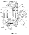
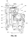
- Figures 1 , 2A , 2B , 3A , 3B and 3C show different views of a hand rehabilitation device 100 according to a possible embodiment of the invention.
- the device 100 is versatile, meaning that it can be configured for rehabilitating either a right hand or a left hand.
- the configuration shown in these figures is a right-hand configuration, but it can simply be switched to a left-hand configuration, as will be explained later in this text.
- the device 100 can be attached to another device or apparatus, such as to a tool robot, a manipulator or an arm support (for example a support fixed on a table), or directly to the arm of the user. It can also act as a hand-held device.
- the portable device 100 is configured to be grasped by the hand to be trained, in such a way that the palm, fingers and thumb (inner part of the hand) surround the grasped device 100.
- the structure 110 is to be grasped by a right-hand, as shown in figure 2B .
- the inner part of the fingers and thumb are disposed on several supports or "finger rests" 120 121 122 123 124 disposed to receive the fingers and thumb, which rest or are supported on the supports.
- a strap can be included, in order to ensure that the fingers are attached to the device. The strap can be especially useful for finger flexion (hand closing movement).
- two finger rests 120 121 are disposed for receiving the respective distal phalanx and at least a portion of the intermediate phalanx (or the whole intermediate phalanx) of the index finger (inner part thereof) and two finger rests 122 123 are disposed for receiving the respective distal phalanx and at least a portion of the intermediate phalanx (or the whole intermediate phalanx) of another group of fingers, formed by middle, ring and little fingers (inner part thereof).
- the two upper finger rests 120 122 end up between the distal and the intermediate phalanx of the index finger and middle, ring and little fingers, respectively, while the two lower finger rests 121 123 end up between the proximal and the intermediate phalanx of the index finger and middle, ring and little fingers, respectively.
- the supports or rests 120 121 for the index finger are attached to a structure (carriage) 139, which holds the transmission mechanism 114 for those rests 120 121.
- Figure 3C shows the attaching means 144 141 for supports 120 121, respectively.
- the supports or rests 122 123 for the middle, ring and little fingers are attached to a structure (carriage) 149 which holds the transmission mechanism 112 for those rests 122 123.
- the view of figure 1 and the rotated view of figure 3A show an additional support or rest 124 for the thumb.
- the disposition of this thumb rest 124 with respect to the other finger rests has been selected to be adapted to the natural shape of the hand.
- the support or rest 124 for the thumb is attached to a structure (carriage) 159 which holds the transmission mechanism 113 for that rest 124.
- a motor 110 for actuating the supports or rests 122 123 for the middle, ring and little fingers the casing of this motor 110 functions as a palm rest for a left hand or as a grasp for the device with a left hand when the device is used for rehabilitating a left hand
- a motor 111 for actuating the supports or rests 120 121 for the index finger the casing of this motor 111 functions as a palm rest for a right hand or as a grasp for the device with a right hand when the device is used for rehabilitating a right hand
- a motor 109 for actuating the support or rest 124 for the thumb a transmission mechanism 112 (held in carriage 149) associated to motor 110; a transmission mechanism 113 (held in carriage 159) associated to motor 109; a transmission mechanism 114 (held in carriage 139) associated to motor 111; and a locking arm 115 for a thumb adjustment mechanism.
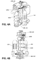
- Figures 4A-4D show a more general embodiment, in which there is a single finger rest 120A for the index finger and a single finger rest 122A for the group of fingers formed by middle, ring and little fingers.
- finger rest 120A ends up between the proximal and the intermediate phalanx of the index finger
- finger rest 122A ends up between the proximal and the intermediate phalanx of the middle, ring and little fingers.
- thumb and corresponding rehabilitation mechanism have been removed for clarity purposes.
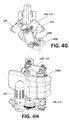
- Figures 4E-4H show an alternative implementation of the more general embodiment, in which there is a single finger rest 120B for the index finger and a single finger rest 122B for the group of fingers formed by middle, ring and little fingers.
- finger rest 120B ends up between the intermediate and the distal phalanx of the index finger
- finger rest 122B ends up between the intermediate and the distal phalanx of the middle, ring and little fingers.
- thumb and corresponding rehabilitation mechanism have also been removed for clarity purposes.
- the supports or finger rests 120 121 120A 120B 122 123 122A 122B 124 are moved, actuated by motors 111 110 109, provoking the flexion/extension of the fingers (and thumb) supported on the corresponding finger rests.
- the device 100 permits independent rehabilitation of the thumb (by means of rest 124 (see for example figure 3A )) and independent rehabilitation of the index finger (by means of finger rest 120A ( figures 4A-4D ) or by means of finger rest 120B ( figures 4E-4H ) or by means of finger rests 120 121 ( figures 1-3C )) with respect to the three remaining fingers, which are rehabilitated in a single group (either on finger rest 122A or on finger rest 122B or on finger rests 122 123).
- the device permits independent rehabilitation (functional flexion/extension) of thumb and index finger, these fingers being the ones involved in most types of grasping movements.
- the remaining fingers -middle, ring and little fingers- are simultaneously moved in a single group.
- the device 100 permits passive rotation of finger supports (finer rests) for self-alignment with hands of varying sizes.
- each transmission mechanism 112 113 114 which enables the flexion/extension of the thumb and fingers is explained.
- Each transmission mechanism 112 113 114 is actuated by a motor 110 109 111.
- the illustrated embodiments show an independent transmission mechanism 113 for the thumb, an independent transmission mechanism 114 for the index and an independent transmission mechanism 112 for the three fingers.
- here is an independent transmission mechanism 113 for the thumb and one single additional independent transmission mechanism for the four fingers. This is achieved by connecting or locking, for example by means of a bar, rest 120A with rest 122A in figure 4A , or rest 120B with rest 122B in figure 4E , or rest 120 with rest 122 and rest 121 with rest 123 in figure 3A or figure 3C .
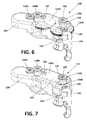
- Figures 6 and 7 show two possible embodiments of the double gearwheel mechanism 130 131.
- the double gearwheel mechanism 130 in figure 6 is based on a double toothed gearwheel.
- the double gearwheel mechanism 131 in figure 7 is based on a double wheel with mechanical coupling.
- a respective motor 111 110 109 not shown in figures 6 and 7 , actuates on a pinion 132, which is rotated by the motor.
- the pinion 132 in turn makes a crown 133 move (the crown 133 is shown in figures 9A-98F ).
- the crown 133 is fixed to the carriage 139 149 159, which houses inside the transmission mechanism 114 112 113 (in this embodiment, double gearwheel mechanism 130 131).
- the crown 133 drags the carriage 139 149 159.
- the structure for rehabilitating an index finger refers similarly to the structures for rehabilitating the three fingers (see for example figures 4A to 4H ) and to the structure for rehabilitating a thumb.
- the support for the intermediate phalanx of the fingers is fixed to the carriage 139 such that the movement of the motor 111 produces an angular displacement of the carriage 139 (by means of the rotation of the crown 133) and a corresponding angular displacement of the support 121 123 for the intermediate phalanx.
- the transmission mechanism 130 131 (double gearwheel) comprises an input wheel 135A 136A and an output wheel 135B 136B.
- Input wheel 135A 136A and output wheel 135B 136B are connected to each other such that the input wheel 135A 136A does not move when the carriage 139 moves (angular displacement) but produces a rotation of the output wheel 135B 136B. Additional features applicable to the particular embodiment in which each finger (index on the one hand and middle, ring and little fingers on the other hand) is rehabilitated in two sections ( figures 1-3C ), are explained next. The following explanation fully applies to the thumb because the distal phalanx support is the same in all three modules (index, fingers, thumb).
- the support 120 122 for the distal phalanx of the finger (distal support) is fixed to the output wheel 125B 136B such that the movement of the motor 110 111 109 produces an angular displacement of the carriage 139 and a corresponding angular displacement of the support 120 122 for the distal phalanx.
- the movement of the carriage 139 produces a rotation of the output wheel 135B 136B and that rotation produces and angular displacement of the support 120 122 for the distal phalanx with respect to the position of the carriage 139.
- the angular displacement of the distal phalanx support 121 123 is greater than the angular displacement of the intermediate phalanx support 120 122.
- the motor 110 111 109 can be selectively activated by the user (or by a therapist) for operation of the device.
- the motor is battery powered a.
- it could be powered by conventional available electricity or pressurized fluid such as compressed air in the case of a device fitted with pneumatic motors.
- the pinion 132 and the crown 133 are not shown because they are housed in a casing, housing or base 134.
- Figure 3B clearly shows motor 109 and its pinion 162, motor 110 and its pinion 172 and motor 111 and its pinion 132.
- the transmission mechanism 130 is formed by two toothed gearwheels: an input toothed gearwheel 135A and an output toothed gearwheel 135B (also referred to as gear train) engaged by respective teeth.
- the input toothed gearwheel 135A is mounted in the rotational axis 160 of the carriage 139 such that when the carriage rotates by the rotation of the crown 133, the input gearwheel 135A does not move.
- the output gearwheel 135B is mounted in the carriage 139 through its axis 180 so the output gearwheel 135B moves when the carriage 139 moves but can rotate freely in the carriage 139.
- the output wheel 135B is forced to rotate over the input gearwheel 135A.
- the intermediate phalanx support 121 123 is fixed to the carriage 139 whilst the distal phalanx support 120 122 is fixed to the output gearwheel 135B. That way, the angular displacement of the intermediate phalanx support 121 123 is the displacement of the carriage 139 whilst the angular displacement of the distal phalanx support 120 122 is the displacement of the carriage plus the rotation of the output gearwheel 135B.
- the angular displacement of the distal phalanx support 121 123 and intermediate phalanx support 120 122 produce the flexion/extension of the fingers (either index finger, thumb or remaining fingers).
- the transmission mechanism (double gearwheel mechanism) 131 is formed by two discs or wheels, an input wheel 136A and an output wheel 136B which do not touch directly each other and a coupling means or mechanical coupling (such as a coupling rod) 137 connecting the two discs or wheels together.
- the coupling means 137 is fixed to the input and output wheels 136A 136B such that the distance between the connecting points of the input and output wheels 136A 136B is fixed.
- the input wheel 136A is mounted in the rotational axis 160 of the carriage 139, such that when the carriage rotates by the rotation of the crown 133, the input wheel 136A does not move.
- the output wheel 136B is mounted in the carriage through its axis 180. So the output wheel 136B moves when the carriage 139 moves, but can rotate freely in the carriage 139.
- the input wheel 136A is engaged to the output wheel 136B (through a coupling rod 137)
- the output wheel 136B is forced to rotate by the connecting rod 137 to maintain the distance between the connecting points of the input and output wheels 136A 136B.
- the proximal phalanx support 121 123 is fixed to the carriage 139 whilst the distal phalanx support 120 122 is fixed to the output wheel 136B. That way the angular displacement of the proximal phalanx support 121 123 is the displacement of the carriage 139, whilst the angular displacement of the distal phalanx support 120 122 is the displacement of the carriage plus the rotation of the output wheel 136B.
- the angular displacement of the distal phalanx support 120 122 and proximal phalanx support 121 123 can produce the flexion/extension of the fingers (either index finger, thumb or remaining fingers).
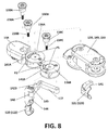
- Figure 8 shows a break-up of the transmission mechanism (double gearwheel mechanism) 131 in figure 7 .
- a first casing, housing or base 134 houses the pinion 132 and partially the crown 133. Note that we refer generally to pinion 132 but we could refer correspondingly to pinion 162 172 (see for example figure 3B ). This is the same as in the transmission mechanism 130 shown in figure 6 .
- a second casing or carriage 139 houses the fixed wheel 136B, the moving wheel 136A and the mechanical coupling 137 (in the transmission mechanism 130 in figure 6 , the carriage 139 houses the double toothed gearwheel). Like in the transmission mechanism (double gearwheel mechanism) 130 in figure 6 , the crown 133 is fixed to the lower part of the carriage 139.
- the input wheel 136A and the output wheel 136B are identical, and are formed by two flat discs disposed parallel to each other and fixed one another by any kind of mechanical attachment 137 (connecting rod) which establishes a fixed distance between the connecting points of the input and output wheels 136A 136B.
- the input wheel 136A and the carriage 139 comprise an elongated canal 141 A, which defines two end positions P1 P2 for the angular displacement of the carriage 139, to control the maximum extension movement possible for the fingers.
- Pin 138B is used to constrain the proximal pivot point for link (mechanical attachment) 137. For a right hand configuration, the pivot point is on the left ( figure 8 top). For a left hand configuration, the pivot point is on the right.
- Pin 138B has the exact function as pin 138A, that is to say, to define the position of the distal pivot point for link (mechanical attachment) 137. For a right hand configuration, the distal pivot point is on the right. For a left hand configuration, the point is on the left.
- Pin 138C is mounted on the carriage 139.
- the shaft 238C of pin 138C is housed in the elongated canal 141 B so that during the angular displacement of the carriage 139, the canal 141 B moves around pin 138C, but collides with the shaft 238C of the pin at the end of the stroke imposed for the carriage 139 (depending on the maximum extension movement established for the fingers).
- Figure 8 shows the particular embodiment in which rehabilitation of the fingers is done in two sections.
- the support or rest for the distal phalanx (120 in the case of index finger, 122 in the case of middle, ring or little fingers) is coupled to the output wheel 136B by means of a part 144 on which the support (120, 122) is fixed.
- This part 144 is connected to the output wheel 136B by means of pivoting means 142 connected in one end to part 144 (for example by means of a screw 145) and in the other end 142B to the output wheel 136B and second housing 139 (for example by means of a screw 146 as shown in figure 6 ).
- FIG. 8 also shows the support for the proximal phalanx (121 in the case of index finger, 123 in the case of middle, ring or little fingers) and the part 141 on which the support is fixed. This part 141 is connected to the support. These parts 141 144 and their corresponding supports are also shown in figure 3C .
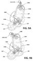
- Figures 9A-9F show several positions of the mechanism of the flexion/extension of the fingers (in this case the mechanism 131 is implemented as shown in figure 7 ). These positions can refer to the index finger, or to the three other fingers and even to the thumb, if two-sections for the two phalanxes were implemented.
- Figures 9A-9C refer to a sequence for a right hand.
- Figure 9A refers to a position with substantially maximum extension while figure 9C refers to a position with substantially maximum flexion.
- Figures 9D-9F refer to sequence for a left hand.
- Figure 9D refers to a position with substantially maximum extension while figure 9F refers to a position with substantially maximum flexion.
- wheel 136A and pin 138B remain fixed with respect to the housing, casing or base 134.
- the carriage 139 rotates actioned by crown 133 in turn actioned by the pinion 162 (or 132 172) moved by a motor (not shown).
- the crown 133 drags carriage 139 and in turn the mechanical coupling 137 moves the output wheel 136B.
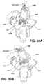
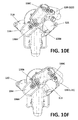
- Figures 10A-10F show several positions of the mechanism of the flexion/extension of the index finger (right hand in figures 10A-10C and left hand in figures 10D-1 OF).
- Figures 11A-11D show different views of the hand rehabilitation device shown for example in figure 1 , but in this case configured to rehabilitate a left hand, which is illustrated in its functional position for rehabilitation.
- the casings of the transmission mechanism 114 for the index finger has been erased, in order to show the functioning of the double gearwheel mechanism 131.
- the transmission mechanism 112 for the group of middle, ring and little fingers works in a similar way.
- the casing 151 in which the motor 110 which actuates the transmission mechanism 112 for the group of middle, ring and little fingers is shown. It is remarked that the location of the motors may vary in different designs of the device.
- Reference 152 is the casing in which motor 111 is housed.
- FIG. 12A-12D show different views of the same hand rehabilitation device, in this case configured to rehabilitate a right hand. Again, the thumb has been erased from these views for clarity purposes.
- the device is reversible. This means that the same device can be used to rehabilitate both a right hand and a left hand.
- the transmission mechanism illustrated in figure 6 does not require any reconfiguration in order to switch from a "right hand configuration" to a "left hand configuration” or vice versa. That is to say, reversibility is automatic.
- Figures 13A-13D illustrate the reversibility capability of the transmission mechanism of figure 7 . Since there are 3 transmission mechanisms in one device (index finger, 3 fingers and thumb), the reconfiguration must be done three times, because each finger requires reorienting wheels 136A and 136B and lock with pins 138B and 138C.
- pins 138B 138C must be lifted, then wheels must be turned, so that the pin naturally locks into position in the opposite end of the circular groove (canal) with the round holes in the ends.
- pins 138B 138C could be one single mechanism in order to simplify the process.
- the thumb lock mechanism also needs to be reconfigured. Turning back to figure 8 , during reconfiguration, the set formed by support 120 (or 122) and part 144 moves freely with respect to screw 145. Similarly, the set formed by support 121 (or 123) and part 141 moves freely with respect to corresponding screw (both if the transmission mechanism in figure 6 and in that in figure 7 ).
- Figures 13A and 13C show the left hand configuration
- figures 13B and 13D show the corresponding right hand reconfiguration.
- the housing or base does not change position.
- Pin 138B which in left-hand configuration is positioned in position P2 (see figure 8 ) in output wheel 136B is moved to position P1 (see figure 8 ).
- the mechanical coupling (transmission bar) 137 becomes naturally re-oriented when the wheels 136A 136B change position.
- Pin 138B also changes position from position P2' (left hand configuration) to position P1' (right hand configuration). Pivoting axis 160 is maintained in both left-hand and right-hand configurations, independently from the positions of motors.
- the casing, housing or carriage 139 pivotes or rotates around this pivoting axis 160.
- Pin 138A does not have any influence in reconfiguration.
- the transmission mechanism shown in figure 6 does not need any change in order to be reconfigured, except for the free movement of the set formed by support 120 (or 122) and part 144 and the free movement of the set formed by support 121 (or 123) and part 141. In both mechanisms, it is possible to add safety pins in order to prevent over-travel of the hand in the event of failure of a motor.
- the device 100 permits two symmetrical grasp modes supported for each of left-hand and right-hand operation: cylindrical mode (for grasping for example a glass) and "open pinch/clamp" for 3-fingered grasp (predominantly MCP action).
- Figures 1 , 2A , 2B , 3A , 3B and 3C show different views of a hand rehabilitation device 100 according to a possible embodiment of the invention.
- the device 100 is versatile, meaning that it can be configured for rehabilitating either a right hand or a left hand.
- the configuration shown in these figures is a right-hand configuration, but it can simply be switched to a left-hand configuration, as will be explained later in this text.
- the device 100 can be attached to another device or apparatus, such as to a tool robot, a manipulator or an arm support (for example a support fixed on a table), or directly to the arm of the user. It can also act as a hand-held device.
- the portable device 100 is configured to be grasped by the hand to be trained, in such a way that the palm, fingers and thumb (inner part of the hand) surround the grasped device 100.
- the structure 110 is to be grasped by a right-hand, as shown in figure 2B .
- the inner part of the fingers and thumb are disposed on several supports or "finger rests" 120 121 122 123 124 disposed to receive the fingers and thumb, which rest or are supported on the supports.
- a strap can be included, in order to ensure that the fingers are attached to the device. The strap can be especially useful for finger flexion (hand closing movement).
- two finger rests 120 121 are disposed for receiving the respective distal phalanx and at least a portion of the intermediate phalanx (or the whole intermediate phalanx) of the index finger (inner part thereof) and two finger rests 122 123 are disposed for receiving the respective distal phalanx and at least a portion of the intermediate phalanx (or the whole intermediate phalanx) of another group of fingers, formed by middle, ring and little fingers (inner part thereof).
- the two upper finger rests 120 122 end up between the distal and the intermediate phalanx of the index finger and middle, ring and little fingers, respectively, while the two lower finger rests 121 123 end up between the proximal and the intermediate phalanx of the index finger and middle, ring and little fingers, respectively.
- the supports or rests 120 121 for the index finger are attached to a structure (carriage) 139, which holds the transmission mechanism 114 for those rests 120 121.
- Figure 3C shows the attaching means 144 141 for supports 120 121, respectively.
- the supports or rests 122 123 for the middle, ring and little fingers are attached to a structure (carriage) 149 which holds the transmission mechanism 112 for those rests 122 123.
- the view of figure 1 and the rotated view of figure 3A show an additional support or rest 124 for the thumb.
- the disposition of this thumb rest 124 with respect to the other finger rests has been selected to be adapted to the natural shape of the hand.
- the support or rest 124 for the thumb is attached to a structure (carriage) 159 which holds the transmission mechanism 113 for that rest 124.
- a motor 110 for actuating the supports or rests 122 123 for the middle, ring and little fingers the casing of this motor 110 functions as a palm rest for a left hand or as a grasp for the device with a left hand when the device is used for rehabilitating a left hand
- a motor 111 for actuating the supports or rests 120 121 for the index finger the casing of this motor 111 functions as a palm rest for a right hand or as a grasp for the device with a right hand when the device is used for rehabilitating a right hand
- a motor 109 for actuating the support or rest 124 for the thumb a transmission mechanism 112 (held in carriage 149) associated to motor 110; a transmission mechanism 113 (held in carriage 159) associated to motor 109; a transmission mechanism 114 (held in carriage 139) associated to motor 111; and a locking arm 115 for a thumb adjustment mechanism.
- Figures 5A to 5C show three views of a more general embodiment, in which there is a single proximal finger rest or support 123C for the proximal phalanx and the intermediate phalanx of index, middle, ring and little fingers; and a single distal finger rest or support 122C for the distal phalanx of index, middle, ring and little fingers.
- the device permits rehabilitation of at least the index, middle, ring and little fingers in two sections: a first section including the proximal phalanx and the intermediate phalanx of each finger; and a second section including the distal phalanx of each finger.
- the distal finger rest 122C ends up between the distal and the intermediate phalanx of the index, middle, ring and little fingers
- the proximal finger rest 123C ends up between the proximal and the intermediate phalanx of the index, middle, ring and little fingers.
- the supports or finger rests 120 121 122 123 122C 123C 124 are moved, actuated by motors 110 111 109 110B (motor 110B is not shown, being the motor for the 4 fingers in figures 5A-5C ), provoking the flexion/extension of the fingers (and thumb) supported on the corresponding finger rests.
- the device 100 permits independent rehabilitation of the thumb (by means of rest 124 (see for example figure 3A )) and rehabilitation in two sections of the four fingers (by means of finger rests 122C 123C ( figures 5A-5C ) or finger rests 120 121 122 123 ( figures 1-3C ).
- independent rehabilitation of the index finger, with respect to the three remaining fingers is achieved, which are rehabilitated in a single group.
- the device apart from rehabilitating the fingers in two sections (a first one for proximal and intermediate phalanxes and a second one for distal phalanxes), the device permits independent rehabilitation (functional flexion/extension) of thumb and index finger, these fingers being the ones involved in most types of grasping movements.
- the remaining fingers -middle, ring and little fingers- are simultaneously moved in a single group.
- the device 100 permits passive rotation of finger supports (finer rests) for self-alignment with hands of varying sizes.
- each transmission mechanism 112 113 114 112B (112 113 114 in figures 1-3C and 112B in figures 5A-5C ) which enables the flexion/extension of the thumb and fingers is explained next.
- Each transmission mechanism 112 113 114 112B is actuated by a motor 110 109 111 110B.
- there are two additional independent transmission mechanisms 112 114 (instead of one 112B): one independent transmission mechanism 114 for the index finger and one independent transmission mechanism 112 for the three remaining fingers.
- This is achieved by connecting or locking, for example by means of a bar, rest 120A with rest 122A in figure 4A , or rest 120B with rest 122B in figure 4E , or rest 120 with rest 122 and rest 121 with rest 123 in figure 3A .
- one of the two motors (motor 111 or motor 110) could be removed.
- the functioning of the several transmission mechanisms is the same and is described next.
- two possible embodiments for the transmission mechanism are described with reference to respective figures 6 and 7 . Both embodiments comprise a double gearwheel mechanism 130 131 and are equivalent within the range of motion (ROM) of interest.
- Figures 9A-9F show several positions of the mechanism of the flexion/extension of the fingers (in this case implemented as shown in figure 7 ).
- Figures 6 and 7 show two possible embodiments of the double gearwheel mechanism 130 131.
- the double gearwheel mechanism 130 in figure 6 is based on a double toothed gearwheel.
- the double gearwheel mechanism 131 in figure 7 is based on a double wheel with mechanical coupling.
- a respective motor 111 110 109 not shown in figures 6 and 7 , actuates on a pinion 132, which is rotated by the motor.
- the pinion 132 in turn makes a crown 133 move (the crown 133 is shown in figures 9A-9F ).
- the crown 133 is fixed to the carriage 139 149 159, which houses inside the transmission mechanism 114 112 113 (in this embodiment, double gearwheel mechanism 130 131).
- the crown 133 drags the carriage 139 149 159.
- Next description applies to a rehabilitating structure for the index finger, of for the 3 fingers (middle, ring and little), or for the 4 fingers (index, middle, ring and little), or for the thumb.
- the support for the intermediate phalanx of the fingers (intermediate support or proximal support) 121 123 123C is fixed to the carriage 139 such that the movement of the motor 111 110 110B produces an angular displacement of the carriage 139 (by means of the rotation of the crown 133) and a corresponding angular displacement of the support 121 123 123C for the intermediate phalanx.
- the transmission mechanism 130 131 (double gearwheel) comprises an input wheel 135A 136A and an output wheel 135B 136B.
- Input wheel 135A 136A and output wheel 135B 136B are connected to each other such that the input wheel 135A 136A does not move when the carriage 139 moves (angular displacement) but produces a rotation of the output wheel 135B 136B. Additional features applicable to the particular embodiment in which each finger (index on the one hand and middle, ring and little fingers on the other hand) is rehabilitated in two sections ( figures 1-3C ), are explained next. The following explanation fully applies to the thumb because the distal phalanx support is the same in all three modules (index, fingers, thumb).
- the support 120 122 122C for the distal phalanx of the finger (distal support) is fixed to the output wheel 135B 136B such that the movement of the motor 110 111 109 110B produces an angular displacement of the carriage 139 and a corresponding angular displacement of the support 120 122 for the distal phalanx.
- the movement of the carriage 139 produces a rotation of the output wheel 135B 136B and that rotation produces and angular displacement of the support 120 122 for the distal phalanx with respect to the position of the carriage 139.
- the angular displacement of the distal phalanx support 120 122 122C is greater than the angular displacement of the intermediate phalanx support 121 123 123C.
- the motor 110 111 109 110B can be selectively activated by the user (or by a therapist) for operation of the device.
- the motor is powered by battery.
- it could be powered by conventional available electricity.
- the pinion 132 and the crown 133 are not shown because they are housed in a casing, housing or base 134.
- Figure 3B clearly shows motor 109 and its pinion 162, motor 110 and its pinion 172 and motor 111 and its pinion 132.
- the transmission mechanism 130 is formed by two toothed gearwheels: an input toothed gearwheel 135A and an output toothed gearwheel 135B (also referred to as gear train) engaged by respective teeth.
- the input toothed gearwheel 135A is mounted in the rotational axis 160 of the carriage 139 such that when the carriage rotates by the rotation of the crown 133, the input gearwheel 135A does not move.
- the output gearwheel 135B is mounted in the carriage 139 through its axis 180 so the output gearwheel 135B moves when the carriage 139 moves but can rotate freely in the carriage 139.
- the output wheel 136B is forced to rotate over the input gearwheel 136A.
- the proximal phalanx support 121 123 123C is fixed to the carriage 139 whilst the distal phalanx support 120 122 122C is fixed to the output gearwheel 135B. That way, the angular displacement of the lower phalanx support 121 123 123C is the displacement of the carriage 139 whilst the angular displacement of the distal phalanx support 120 122 122C is the displacement of the carriage plus the rotation of the output gearwheel 135B.
- the angular displacement of the distal phalanx support 120 122 122C and proximal phalanx support 121 123 123C can produce the flexion/extension of the fingers (either index finger, thumb or remaining fingers).
- the transmission mechanism (double gearwheel mechanism) 131 is formed by two discs or wheels, an input wheel 136A and an output wheel 136B which do not touch directly each other and a coupling means or mechanical coupling (such as a coupling rod) 137 connecting the two discs or wheels together.
- the coupling means 137 is fixed to the input and output wheels 136A 136B such that the distance between the connecting points of the input and output wheels 136A 136B is fixed.
- the input wheel 136A is mounted in the rotational axis 160 of the carriage 139, such that when the carriage rotates by the rotation of the crown 133, the input wheel 136A does not move.
- the output wheel 136B is mounted in the carriage through its axis 180. So the output wheel 136B moves when the carriage 139 moves, but can rotate freely in the carriage 139.
- the input wheel 136A is engaged to the output wheel 136B (through a coupling rod 137)
- the output wheel 136B is forced to rotate by the connecting rod 137 to maintain the distance between the connecting points of the input and output wheels 136A 136B.
- the proximal phalanx support 121 123 123C is fixed to the carriage 139 whilst the distal phalanx support 120 122 122C is fixed to the output wheel 136B. That way the angular displacement of the proximal phalanx support 121 123 123C is the displacement of the carriage 139, whilst the angular displacement of the distal phalanx support 120 122 122C is the displacement of the carriage plus the rotation of the output wheel 136B.
- the angular displacement of the distal phalanx support 120 122 122C and proximal phalanx support 121 123 123C can produce the flexion/extension of the fingers (either index finger, thumb or remaining fingers).
- Figure 8 shows a break-up of the transmission mechanism (double gearwheel mechanism) 131 in figure 7 .
- a first casing, housing or base 134 houses the pinion 132 and partially the crown 133. Note that we refer generally to pinion 132 but we could refer correspondingly to pinion 162 172 (see for example figure 3B ). This is the same as in the transmission mechanism 130 shown in figure 6 .
- a second casing or carriage 139 houses the fixed wheel 136B, the moving wheel 136A and the mechanical coupling 137 (in the transmission mechanism 130 in figure 6 , the carriage 139 houses the double toothed gearwheel). Like in the transmission mechanism (double gearwheel mechanism) 130 in figure 6 , the crown 133 is fixed to the lower part of the carriage 139.
- the input wheel 136A and the output wheel 136B are identical, and are formed by two flat discs disposed parallel to each other and fixed one another by any kind of mechanical attachment 137 (connecting rod) which establishes a fixed distance between the connecting points of the input and output wheels 136A 136B.
- the input wheel 136A and the carriage 139 comprise an elongated canal 141 A, which defines two end positions P1 P2 for the angular displacement of the carriage 139, to control the maximum extension movement possible for the fingers.
- Pin 138B is used to constrain the proximal pivot point for link (mechanical attachment) 137. For a right hand configuration, the pivot point is on the left ( figure 8 top). For a left hand configuration, the pivot point is on the right.
- Pin 138B has the exact function as pin 138A, that is to say, to define the position of the distal pivot point for link (mechanical attachment) 137. For a right hand configuration, the distal pivot point is on the right. For a left hand configuration, the point is on the left.
- Pin 138C is mounted on the carriage 139.
- the shaft 238C of pin 138C is housed in the elongated canal 141 B so that during the angular displacement of the carriage 139, the canal 141 B moves around pin 138C, but collides with the shaft 238C of the pin at the end of the stroke imposed for the carriage 139 (depending on the maximum extension movement established for the fingers).
- Figure 8 shows the particular embodiment in which rehabilitation of the fingers is done in two sections.
- the support or rest for the distal phalanx (120 in the case of index finger, 122 in the case of middle, ring or little fingers, 123C in the case of a single distal support for the four fingers together) is coupled to the output wheel 136B by means of a part 144 on which the support (120, 122, 123C) is fixed.
- This part 144 is connected to the output wheel 136B by means of pivoting means 142 connected in one end to part 144 (for example by means of a screw 145) and in the other end 142B to the output wheel 136B and second housing 139 (for example by means of a screw 146).
- FIG. 8 also shows the support for the proximal phalanx (121 in the case of index finger, 123 in the case of middle, ring or little fingers, 123C in the case of 4 fingers) and the part 141 on which the support is fixed. This part 141 is connected to the support. These parts 141 144 and their corresponding supports are also shown in figure 3C .
- Figures 9A-9F show several positions of the mechanism of the flexion/extension of the fingers (in this case the mechanism 131 is implemented as shown in figure 7 ). These positions can refer to the index finger, or to the three other fingers, or to the four fingers together, and even to the thumb, if two-sections for the two phalanxes were implemented.
- Figures 9A-9C refer to a sequence for a right hand.
- Figure 9A refers to a position with substantially maximum extension while figure 9C refers to a position with substantially maximum flexion.
- Figures 9D-9F refer to sequence for a left hand.
- Figure 9D refers to a position with substantially maximum extension while figure 9F refers to a position with substantially maximum flexion.
- wheel 136A and pin 138B remain fixed with respect to the housing, casing or base 134.
- the carriage 139 rotates actioned by crown 133 in turn actioned by the pinion 162 (or 132 172) moved by a motor (not shown).
- the crown 133 drags carriage 139 and in turn the mechanical coupling 137 moves the output wheel 136B.
- Figures 10A-10F show several positions of the mechanism of the flexion/extension of the index finger (right hand in figures 10A-10C and left hand in figures 10D-10F ).
- Figures 11A-11D show different views of the hand rehabilitation device shown for example in figure 1 , but in this case configured to rehabilitate a left hand, which is illustrated in its functional position for rehabilitation.
- the casings of the transmission mechanism for the index finger has been erased, in order to show the functioning of the double gearwheel mechanism 131.
- the transmission mechanism 112 for the group of middle, ring and little fingers works in a similar way.
- the transmission mechanism 112C for the group of index, middle, ring and little fingers works in a similar way.
- the casing 151 in which the motor 110 which actuates the transmission mechanism 112 for the group of middle, ring and little fingers is shown. It is remarked that the location of the motors may vary in different designs of the device.
- Reference 152 is the casing in which motor 111 is housed.
- the casing that houses the transmission mechanism 114 for the index has been erased, in order to show the transmission mechanism 114.
- the transmission mechanism 112 for the three fingers is also shown (in this case hidden by its casing).
- the thumb has been erased from these views for clarity purposes.
- Figures 12A-12D show different views of the same hand rehabilitation device, in this case configured to rehabilitate a right hand. Again, the thumb has been erased from these views for clarity purposes.
- the device is reversible. This means that the same device can be used to rehabilitate both a right hand and a left hand.
- the transmission mechanism illustrated in figure 6 does not require any reconfiguration in order to switch from a "right hand configuration" to a "left hand configuration” or vice versa. That is to say, reversibility is automatic.
- Figures 13A-13D illustrate the reversibility capability of the transmission mechanism of figure 7 . Since there are 3 transmission mechanisms in one device (index finger, 3 fingers and thumb), the reconfiguration must be done three times, because each finger requires reorienting wheels 136A and 136B and lock with pins 138B and 138C.
- pins 138B 138C must be lifted, then wheels must be turned, so that the pin naturally locks into position in the opposite end of the circular groove (canal) with the round holes in the ends.
- pins 138B 138C could be one single mechanism in order to simplify the process.
- the thumb lock mechanism also needs to be reconfigured. Turning back to figure 8 , during reconfiguration, the set formed by support 120 (or 122) and part 144 moves freely with respect to screw 145. Similarly, the set formed by support 121 (or 123) and part 141 moves freely with respect to corresponding screw (both if the transmission mechanism in figure 6 and in that in figure 7 ).
- Figures 13A and 13C show the left hand configuration
- figures 13B and 13D show the corresponding right hand reconfiguration.
- the housing or base does not change position.
- Pin 138B which in left-hand configuration is positioned in position P2 (see figure 8 ) in output wheel 136B is moved to position P1 (see figure 8 ).
- the mechanical coupling (transmission bar) 137 becomes naturally re-oriented when the wheels 136A 136B change position.
- Pin 138B also changes position from position P2' (left hand configuration) to position P1' (right hand configuration). Pivoting axis 160 is maintained in both left-hand and right-hand configurations, independently from the positions of motors.
- the second casing, housing or carriage 139 pivotes or rotates around this pivoting axis 160.
- Pin 138A does not have any influence in reconfiguration.
- the transmission mechanism shown in figure 6 does not need any change in order to be reconfigured, except for the free movement of the set formed by support 120 (or 122) and part 144 and the free movement of the set formed by support 121 (or 123) and part 141. In both mechanisms, it is possible to add safety pins in order to prevent over-travel of the hand in the event of failure of a motor.
- the device 100 permits two symmetrical grasp modes supported for each of left-hand and right-hand operation: cylindrical mode (for grasping for example a glass) and "open pinch/clamp" for 3-fingered grasp (predominantly MCP action).
- a simple, portable, hand-held device for rehabilitation permits independent rehabilitation (flexion/extension) of the thumb and independent rehabilitation (flexion/extension) of the index finger with respect to the remaining fingers (middle, ring and little fingers), which are rehabilitated in a group.
- the device permits rehabilitation of the fingers in two flexion/extension sections: a first one for the proximal and intermediate phalanxes and a second one of the distal phalanxes.
- This double-section rehabilitation permits to open a finger in a natural way, without forcing its joints.
- the device is reversible, meaning that with a simple reconfiguration that can be done by the user or by a therapist, the very same device can be used to rehabilitate an impaired right hand and an impaired left hand.
Landscapes
- Health & Medical Sciences (AREA)
- Epidemiology (AREA)
- Pain & Pain Management (AREA)
- Physical Education & Sports Medicine (AREA)
- Rehabilitation Therapy (AREA)
- Life Sciences & Earth Sciences (AREA)
- Animal Behavior & Ethology (AREA)
- General Health & Medical Sciences (AREA)
- Public Health (AREA)
- Veterinary Medicine (AREA)
- Rehabilitation Tools (AREA)
Abstract
Description
- The present invention relates to the field of devices for rehabilitation of impaired limbs and, in particular, to devices for rehabilitation of impaired hands and fingers.
- Finger function can be lost or damaged as a result of neurological injuries, such as stroke, spinal cord injuries, traumatic brain injuries or Parkinson disease. For example, stroke may cause paralysis of one side of the body. Examples of damaged finger functions are failure to extend fingers, poor finger coordination, loss of finger independence, poor grasping or manipulation ability and inability to control constant grip force. Since the brain has certain capacity to reorganize the damaged neural connections, a partial (or even complete) recovery of the damaged functions is possible.
- There exist active apparatuses for hand rehabilitation, including finger rehabilitation. Such rehabilitation aims at stimulating the recovery, usually by performing repeated movements involving the impaired limb.
- One well-known type of hand rehabilitation systems is based on exoskeletons, which are robotic skeletons that externally embrace a limb or part of the body. For example, United States patent
US-5516249-A describes an exoskeletal control apparatus based on a glove framework into which a hand can be inserted. A similar system is disclosed in United States patentUS-8574178-B2 . This type of devices is complex because they have a lot of moving parts, which results in expensive maintenance. Besides, they require long time to fit a patient's hand to the device. - There are also less-complex finger rehabilitation systems, such as the one disclosed in International patent application
WO-2010/140984-A1 , which comprises a support on which an impaired arm is fixed and five sub-systems, each of them comprising a finger fixation (strap) and a clutch system. Each finger strap is actuated by means of a cable (guided through a pulley) pulling in one direction and a bow spring in the other. However, this system is hardly portable due to its non-compactness. Besides, a force is applied on each finger fixation and is therefore concentrated on a finger joint, therefore causing a potential damage on the joint and not optimizing the finger function rehabilitation. Additionally, finger flexion is provided exclusively by the bow spring component, not the motor, which makes the applied control to the fingers harder to control. - Finally, the availability of simple low-cost devices could extend the duration of rehabilitation, allowing robot-supported exercises at the patient's home, under remote monitoring and/or evaluation by the therapists. International patent application number
WO2015/024852A1 discloses a hand motion exercising device having a movement unit dedicated to the thumb and a movement unit dedicated to the fingers. Both movement units are driven by a single motor. Besides, conventional hand rehabilitation devices, including the one disclosed inWO2015/024852A1 , are designed to be used with either a right hand or a left hand, which results in requiring high investment. - Therefore, there is a need to provide a finger function rehabilitation device which has a simple portable structure and, at the same time, permits an optimized rehabilitation of the five fingers of both a right hand and a left hand.
- It is an object of the invention to provide a portable modular device for hand rehabilitation. The different functions of the different fingers are optimized with the proposed device, because it permits independent rehabilitation (functional flexion/extension) of thumb and index finger, involved in most types of grasping. The remaining fingers -middle, ring and little fingers- are simultaneously moved in a single group. The proposed device, which is a hand-held device, mobilizes fingers by constraining fingertips along their natural, stereotypical trajectory for grasping tasks.
- According to an aspect of the present invention, a device is provided for a hand rehabilitation device that comprises: at least one first support configured to support the thumb of a hand, wherein said at least one first support is designed to perform a flexion/extension movement for rehabilitating said thumb, said flexion/extension movement being actioned by a first transmission mechanism to which the at least one first support is connected; at least one second support configured to support the index finger of said hand, wherein said at least one second support is designed to perform a flexion/extension movement for rehabilitating said index finger, said flexion/extension movement being actioned by a second transmission mechanism to which the at least one second support is connected; at least one third support configured to support the three remaining fingers -middle ring, and little fingers- of said hand, wherein said at least one third support is designed to perform a flexion/extension movement for rehabilitating said three remaining fingers, said flexion/extension movement being actioned by a third transmission mechanism to which the at least one third support is connected; wherein said first transmission mechanism is actuated by one motor different from the at least one motor configured to actuate said second and third transmission mechanisms; wherein the three flexion/extension movements of said at least one first support, said at least one second support and said at least one third support are independent from each other.
- In a particular embodiment, at least one of said first, second and third transmission mechanisms comprises a pinion and a crown configured to move actioned by said pinion, which in turn is configured to rotate actioned by said motor. Still more particularly, upon rotation, said crown is configured to pull two crown gears interconnected by respective protrusions or teeth, causing said supports to move in flexion/extension way. Alternatively, upon rotation, said crown is configured to pull an assembly formed by two wheels and coupling means connecting said two wheels together, wherein the wheel closest to the pinion is fixed and the other wheel and the coupling means move as a result of the movement of the crown.
- In a particular embodiment, said at least one second support comprises a single support for the index finger and said at least one third support comprises a single support for the three remaining fingers -middle ring, and little fingers.
- In a particular embodiment, said at least one second support comprises one distal support for the distal phalanx of the index finger and one proximal support for the intermediate phalanx of the index finger, and said at least one third support comprises one distal support for the distal phalanx of the three remaining fingers -middle ring, and little fingers and one proximal support for the intermediate phalanx of the three remaining fingers -middle ring, and little fingers. Preferably, said at least one first support, said one distal support for the distal phalanx of the index finger and said one distal support for the distal phalanx of the three remaining fingers -middle ring, and little fingers- are coupled to the movable wheel of respective transmission mechanisms by means of a part that attaches to a pivot in the respective transmission mechanism.
- In a particular embodiment, said at least one first support, said at least one second support and said at least one third support are coupled to respective transmission mechanisms by means of a part that attaches to a pivot in the respective transmission mechanism.
- In a particular embodiment, the device is reversible and therefore a same device serves at rehabilitating a right hand and a left hand. The device is reversible: either by moving freely a set formed by a support and a part with respect to a pivoting means, when the transmission mechanism comprises two crown gears interconnected by respective protrusions or teeth; or by lifting pins and turning wheels until the corresponding pin naturally locks into a position in the opposite end of a canal and by moving freely a set formed by a support and a part with respect to a pivoting means, when the transmission mechanism comprises two wheels and coupling means connecting said two wheels together.
- In a particular embodiment each one of said first, second and third transmission mechanisms is actuated by one corresponding motor.
- It is another object of the invention to provide a portable modular device for hand rehabilitation configured for rehabilitation of at least the index, middle, ring and little fingers in two sections: a first section for the lower (proximal) phalanx and the intermediate phalanx of each finger; and a second section for the upper (distal) phalanx of each finger. With this double movement (movement in two sections) the flexion/extension of each finger is performed in a natural way, without forcing the joints.
- According to another aspect of the present invention, a hand rehabilitation device is provided, that comprises: at least one first support configured to support the thumb of a hand, wherein said at least one first support is designed to perform a flexion/extension movement for rehabilitating said thumb, said flexion/extension movement being actioned by a first transmission mechanism to which the at least one first support is connected; at least one proximal support configured to support the intermediate phalanx of at least the middle, ring and little fingers of said hand, wherein said at least one proximal support is designed to perform a flexion/extension movement of said intermediate phalanxes of said fingers, actioned by at least one second transmission mechanism to which the at least one proximal support is connected; at least one distal support configured to support the distal phalanx of at least the middle, ring and little fingers of said hand, wherein said at least one distal support is designed to perform an additional flexion/extension movement of said distal phalanxes of said fingers with respect to the flexion/extension movement of said intermediate phalanxes of said fingers, actioned by said at least one second transmission mechanism to which the at least one distal support is connected; wherein said first transmission mechanism is actuated by one motor different from the at least one motor configured to actuate said at least one second transmission mechanisms; wherein the flexion/extension movement of said at least one first support is independent from the flexion/extension movements of said at least one proximal support and at least one distal support.
- In a particular embodiment, at least one of said first and transmission mechanisms comprises a pinion and a crown configured to move actioned by said pinion, which in turn is configured to rotate actioned by said motor. Still more particularly, upon rotation, said crown is configured to pull two crown gears interconnected by respective protrusions or teeth, causing said supports to move in flexion/extension way. Alternatively, upon rotation, said crown is configured to pull an assembly formed by two wheels and coupling means connecting said two wheels together, wherein the wheel closest to the pinion is fixed and the other wheel and the coupling means move as a result of the movement of the crown.
- In a particular embodiment, said at least one proximal support comprises a single support for the intermediate phalanxes of said index, middle, ring and little fingers and said at least one distal support comprises a single support for the distal phalanxes of said index, middle, ring and little fingers.
- In a particular embodiment, said at least one first support and said at least one proximal support are coupled to respective transmission mechanisms by means of a part that attaches to a pivot in the respective transmission mechanism and said at least one distal support are coupled to respective transmission mechanisms by means of a part that attaches to a pivot in the respective transmission mechanism.
- In a particular embodiment, said at least one proximal support comprises a first support for the intermediate phalanx of said index finger and a second support for the intermediate phalanx of said middle, ring and little fingers; and said at least one distal support comprises a third support for the distal phalanx of said index finger and a fourth support for the distal phalanxes of said middle, ring and little fingers. Preferably, the device further comprises one transmission mechanism for actuating said first proximal support for the intermediate phalanx of the index finger and said third distal support for the distal phalanx of the index finger and another transmission mechanism for actuating said second proximal support for the intermediate phalanx of the middle, ring and little fingers and said fourth distal support for the distal phalanx of the middle, ring and little fingers.
- In a particular embodiment, the device is reversible and therefore a same device serves at rehabilitating a right hand and a left hand. The device is reversible: either by moving freely a set formed by a support and a part with respect to a pivoting means, when the transmission mechanism comprises two crown gears interconnected by respective protrusions or teeth; or by lifting pins and turning wheels until the corresponding pin naturally locks into a position in the opposite end of a canal and by moving freely a set formed by a support and a part with respect to a pivoting means, when the transmission mechanism comprises two wheels and coupling means connecting said two wheels together.
- In a particular embodiment, each one of said at least two transmission mechanisms is actuated by one corresponding motor.
- Additional advantages and features of the invention will become apparent from the detail description that follows and will be particularly pointed out in the appended claims.
- To complete the description and in order to provide a better understanding of the invention, a set of drawings is provided. Said drawings form an integral part of the description and illustrate an embodiment of the invention, which should not be interpreted as restricting the scope of the invention, but just as an example of how the invention can be carried out. The drawings comprise the following figures:
-
Figure 1 shows a view of a hand rehabilitation device configured for rehabilitating a right hand, according to a possible embodiment of the invention. -
Figure 2A shows a different view of the hand rehabilitation device offigure 1 . -
Figure 2B shows the same view as shown infigure 2A , of the hand rehabilitation device, wherein a right hand in its functional position has been illustrated. -
Figures 3A and3B show different views of the hand rehabilitation device offigure 1 . -
Figure 3C shows in detail the finger supports for the four fingers (hand rehabilitation device offigure 1 ). -
Figures 4A to 4D show different views of a hand rehabilitation device according to a more general embodiment of the invention. In this embodiment, there is a single finger rest for the index finger and a single finger rest for the group of fingers formed by middle, ring and little fingers.Figures 4E to 4H show an alternative implementation of this more general embodiment. -
Figures 5A to 5C show different views of a hand rehabilitation device according to an additional alternative embodiment of the invention. -
Figure 6 shows a transmission mechanism according to a possible embodiment of the invention. -
Figure 7 shows a transmission mechanism according to an alternative embodiment of the invention. -
Figure 8 shows a break-up of the transmission mechanism infigure 7 . -
Figures 9A-9F show several positions of the flexion/extension mechanism for the finger support shown infigure 7 . Infigures 9A-9C , the flexion/extension mechanism for the finger support is configured for rehabilitating a right hand. Infigures 9D-9F it is configured for rehabilitating a left hand. -
Figures 10A-10F show several positions of the mechanism for the flexion/extension of the finger shown infigures 7 ,8 and9A-9F (figures 10A-10C right hand;figures 10D-10F left hand). -
Figures 11A-11D show the rehabilitation device infigures 1-3 , configured for rehabilitating a left hand, which is included. For clarity reasons the thumb has been erased from the view. -
Figures 12A-12D show the rehabilitation device infigures 1-3 , configured for rehabilitating a right hand, which is included. For clarity reasons the thumb has been erased from the view. -
Figures 13A-13D show the reversibility capability of the transmission mechanism of the device.Figures 13A and13C show the left hand configuration, whilefigures 13B and13D show the corresponding right hand configuration. - In this text, the term "comprises" and its derivations (such as "comprising", etc.) should not be understood in an excluding sense, that is, these terms should not be interpreted as excluding the possibility that what is described and defined may include further elements, steps, etc.
- In the context of the present invention, the term "approximately" and terms of its family (such as "approximate", etc.) should be understood as indicating values very near to those which accompany the aforementioned term. That is to say, a deviation within reasonable limits from an exact value should be accepted, because a skilled person in the art will understand that such a deviation from the values indicated is inevitable due to measurement inaccuracies, etc. The same applies to the terms "about" and "around" and "substantially".
- The following description is not to be taken in a limiting sense but is given solely for the purpose of describing the broad principles of the invention. Next embodiments of the invention will be described by way of example, with reference to the above-mentioned drawings showing apparatuses and results according to the invention.
-
Figures 1 ,2A ,2B ,3A ,3B and3C show different views of ahand rehabilitation device 100 according to a possible embodiment of the invention. Thedevice 100 is versatile, meaning that it can be configured for rehabilitating either a right hand or a left hand. The configuration shown in these figures is a right-hand configuration, but it can simply be switched to a left-hand configuration, as will be explained later in this text. Thedevice 100 can be attached to another device or apparatus, such as to a tool robot, a manipulator or an arm support (for example a support fixed on a table), or directly to the arm of the user. It can also act as a hand-held device. - The
portable device 100 is configured to be grasped by the hand to be trained, in such a way that the palm, fingers and thumb (inner part of the hand) surround the graspeddevice 100. In this particular implementation, thestructure 110 is to be grasped by a right-hand, as shown infigure 2B . When grasping the hand-helddevice 100 by an impaired hand, the inner part of the fingers and thumb are disposed on several supports or "finger rests" 120 121 122 123 124 disposed to receive the fingers and thumb, which rest or are supported on the supports. Optionally, a strap can be included, in order to ensure that the fingers are attached to the device. The strap can be especially useful for finger flexion (hand closing movement). In the shown embodiment, two finger rests 120 121 are disposed for receiving the respective distal phalanx and at least a portion of the intermediate phalanx (or the whole intermediate phalanx) of the index finger (inner part thereof) and two finger rests 122 123 are disposed for receiving the respective distal phalanx and at least a portion of the intermediate phalanx (or the whole intermediate phalanx) of another group of fingers, formed by middle, ring and little fingers (inner part thereof). In other words, the two upper finger rests 120 122 end up between the distal and the intermediate phalanx of the index finger and middle, ring and little fingers, respectively, while the two lower finger rests 121 123 end up between the proximal and the intermediate phalanx of the index finger and middle, ring and little fingers, respectively. As shown for example infigure 3A , the supports or rests 120 121 for the index finger are attached to a structure (carriage) 139, which holds the transmission mechanism 114 for those rests 120 121.Figure 3C shows the attaching means 144 141 forsupports 120 121, respectively. Similarly, the supports or rests 122 123 for the middle, ring and little fingers are attached to a structure (carriage) 149 which holds thetransmission mechanism 112 for those rests 122 123. The view offigure 1 and the rotated view offigure 3A show an additional support or rest 124 for the thumb. The disposition of thisthumb rest 124 with respect to the other finger rests has been selected to be adapted to the natural shape of the hand. The support or rest 124 for the thumb is attached to a structure (carriage) 159 which holds thetransmission mechanism 113 for thatrest 124. In the figures, other elements can be observed, such as: amotor 110 for actuating the supports or rests 122 123 for the middle, ring and little fingers (the casing of thismotor 110 functions as a palm rest for a left hand or as a grasp for the device with a left hand when the device is used for rehabilitating a left hand); amotor 111 for actuating the supports or rests 120 121 for the index finger (the casing of thismotor 111 functions as a palm rest for a right hand or as a grasp for the device with a right hand when the device is used for rehabilitating a right hand); amotor 109 for actuating the support or rest 124 for the thumb; a transmission mechanism 112 (held in carriage 149) associated tomotor 110; a transmission mechanism 113 (held in carriage 159) associated tomotor 109; a transmission mechanism 114 (held in carriage 139) associated tomotor 111; and alocking arm 115 for a thumb adjustment mechanism. -
Figures 4A-4D show a more general embodiment, in which there is asingle finger rest 120A for the index finger and asingle finger rest 122A for the group of fingers formed by middle, ring and little fingers. In this case, finger rest 120A ends up between the proximal and the intermediate phalanx of the index finger, while finger rest 122A ends up between the proximal and the intermediate phalanx of the middle, ring and little fingers. In these views the thumb and corresponding rehabilitation mechanism have been removed for clarity purposes. -
Figures 4E-4H show an alternative implementation of the more general embodiment, in which there is asingle finger rest 120B for the index finger and asingle finger rest 122B for the group of fingers formed by middle, ring and little fingers. In this case,finger rest 120B ends up between the intermediate and the distal phalanx of the index finger, whilefinger rest 122B ends up between the intermediate and the distal phalanx of the middle, ring and little fingers. In these views the thumb and corresponding rehabilitation mechanism have also been removed for clarity purposes. - As will be explained later, in use of the device, the supports or finger rests 120 121
120A 120B122A 122Bmotors 111 110 109, provoking the flexion/extension of the fingers (and thumb) supported on the corresponding finger rests. As can be observed, thedevice 100 permits independent rehabilitation of the thumb (by means of rest 124 (see for examplefigure 3A )) and independent rehabilitation of the index finger (by means offinger rest 120A (figures 4A-4D ) or by means offinger rest 120B (figures 4E-4H ) or by means of finger rests 120 121 (figures 1-3C )) with respect to the three remaining fingers, which are rehabilitated in a single group (either onfinger rest 122A or onfinger rest 122B or on finger rests 122 123). Thus, the device permits independent rehabilitation (functional flexion/extension) of thumb and index finger, these fingers being the ones involved in most types of grasping movements. The remaining fingers -middle, ring and little fingers- are simultaneously moved in a single group. Thedevice 100 permits passive rotation of finger supports (finer rests) for self-alignment with hands of varying sizes. - Next, the
transmission mechanism 113 112 114 which enables the flexion/extension of the thumb and fingers is explained. Eachtransmission mechanism 112 113 114 is actuated by amotor 110 109 111. The illustrated embodiments show anindependent transmission mechanism 113 for the thumb, an independent transmission mechanism 114 for the index and anindependent transmission mechanism 112 for the three fingers. In an alternative embodiment, here is anindependent transmission mechanism 113 for the thumb and one single additional independent transmission mechanism for the four fingers. This is achieved by connecting or locking, for example by means of a bar,rest 120A withrest 122A infigure 4A , or rest 120B withrest 122B infigure 4E , or rest 120 withrest 122 and rest 121 withrest 123 infigure 3A orfigure 3C . In any of these cases, one of the two motors (motor 111 or motor 110) could be removed. In the particular embodiment in which there is independent rehabilitation of the index finger, there are two independent transmission mechanisms (instead of one): one independent transmission mechanism 114 for the index finger and oneindependent transmission mechanism 112 for the three remaining fingers. The functioning of the several transmission mechanisms is the same and is described next. Next, two possible embodiments for thetransmission mechanism 112 113 114 are described with reference to respectivefigures 6 and 7 . Both embodiments comprise adouble gearwheel mechanism 130 131 and are equivalent within the range of motion (ROM) of interest.Figures 9A-9F show several positions of the mechanism of the flexion/extension of the fingers (in this case implemented as shown infigure 7 ). -
Figures 6 and 7 show two possible embodiments of thedouble gearwheel mechanism 130 131. Thedouble gearwheel mechanism 130 infigure 6 is based on a double toothed gearwheel. Thedouble gearwheel mechanism 131 infigure 7 is based on a double wheel with mechanical coupling. In bothimplementations 130 131 of the mechanism, arespective motor 111 110 109, not shown infigures 6 and 7 , actuates on apinion 132, which is rotated by the motor. Thepinion 132 in turn makes acrown 133 move (thecrown 133 is shown infigures 9A-98F ). Thecrown 133 is fixed to thecarriage 139 149 159, which houses inside the transmission mechanism 114 112 113 (in this embodiment,double gearwheel mechanism 130 131). In its movement (rotation), thecrown 133 drags thecarriage 139 149 159. Next we refer to the particular case of the structure for rehabilitating an index finger. However, the following explanation refers similarly to the structures for rehabilitating the three fingers (see for examplefigures 4A to 4H ) and to the structure for rehabilitating a thumb. The support for the intermediate phalanx of the fingers (intermediate support or proximal support) is fixed to thecarriage 139 such that the movement of themotor 111 produces an angular displacement of the carriage 139 (by means of the rotation of the crown 133) and a corresponding angular displacement of thesupport 121 123 for the intermediate phalanx. Thetransmission mechanism 130 131 (double gearwheel) comprises aninput wheel 135Aoutput wheel 135BInput wheel 135Aoutput wheel 135Binput wheel 135Acarriage 139 moves (angular displacement) but produces a rotation of theoutput wheel 135Bfigures 1-3C ), are explained next. The following explanation fully applies to the thumb because the distal phalanx support is the same in all three modules (index, fingers, thumb). Thesupport 120 122 for the distal phalanx of the finger (distal support) is fixed to theoutput wheel 125B 136B such that the movement of themotor 110 111 109 produces an angular displacement of thecarriage 139 and a corresponding angular displacement of thesupport 120 122 for the distal phalanx. In addition, the movement of thecarriage 139 produces a rotation of theoutput wheel 135Bsupport 120 122 for the distal phalanx with respect to the position of thecarriage 139. As explained, the angular displacement of thedistal phalanx support 121 123 is greater than the angular displacement of theintermediate phalanx support 120 122. - The
motor 110 111 109 can be selectively activated by the user (or by a therapist) for operation of the device. In a preferred embodiment, the motor is battery powered a. Alternatively, it could be powered by conventional available electricity or pressurized fluid such as compressed air in the case of a device fitted with pneumatic motors. For simplicity reasons, infigures 6 and 7 thepinion 132 and thecrown 133 are not shown because they are housed in a casing, housing orbase 134.Figure 3B clearly showsmotor 109 and itspinion 162,motor 110 and itspinion 172 andmotor 111 and itspinion 132. - In
figure 6 , the transmission mechanism (double gearwheel mechanism) 130 is formed by two toothed gearwheels: an inputtoothed gearwheel 135A and an outputtoothed gearwheel 135B (also referred to as gear train) engaged by respective teeth. The inputtoothed gearwheel 135A is mounted in therotational axis 160 of thecarriage 139 such that when the carriage rotates by the rotation of thecrown 133, theinput gearwheel 135A does not move. Theoutput gearwheel 135B is mounted in thecarriage 139 through itsaxis 180 so theoutput gearwheel 135B moves when thecarriage 139 moves but can rotate freely in thecarriage 139. As theinput gearwheel 135A is engaged to theoutput gearwheel 135B (through a toothed edge) when the movement of thecarriage 139 drags theoutput gearwheel 135A, theoutput wheel 135B is forced to rotate over theinput gearwheel 135A. Theintermediate phalanx support 121 123 is fixed to thecarriage 139 whilst thedistal phalanx support 120 122 is fixed to theoutput gearwheel 135B. That way, the angular displacement of theintermediate phalanx support 121 123 is the displacement of thecarriage 139 whilst the angular displacement of thedistal phalanx support 120 122 is the displacement of the carriage plus the rotation of theoutput gearwheel 135B. The angular displacement of thedistal phalanx support 121 123 andintermediate phalanx support 120 122 produce the flexion/extension of the fingers (either index finger, thumb or remaining fingers). - In
figure 7 , the transmission mechanism (double gearwheel mechanism) 131 is formed by two discs or wheels, aninput wheel 136A and anoutput wheel 136B which do not touch directly each other and a coupling means or mechanical coupling (such as a coupling rod) 137 connecting the two discs or wheels together. The coupling means 137 is fixed to the input andoutput wheels 136Aoutput wheels 136A - The
input wheel 136A is mounted in therotational axis 160 of thecarriage 139, such that when the carriage rotates by the rotation of thecrown 133, theinput wheel 136A does not move. Theoutput wheel 136B is mounted in the carriage through itsaxis 180. So theoutput wheel 136B moves when thecarriage 139 moves, but can rotate freely in thecarriage 139. As theinput wheel 136A is engaged to theoutput wheel 136B (through a coupling rod 137), when the movement of thecarriage 139 drags theoutput wheel 136B, theoutput wheel 136B is forced to rotate by the connectingrod 137 to maintain the distance between the connecting points of the input andoutput wheels 136Aproximal phalanx support 121 123 is fixed to thecarriage 139 whilst thedistal phalanx support 120 122 is fixed to theoutput wheel 136B. That way the angular displacement of theproximal phalanx support 121 123 is the displacement of thecarriage 139, whilst the angular displacement of thedistal phalanx support 120 122 is the displacement of the carriage plus the rotation of theoutput wheel 136B. The angular displacement of thedistal phalanx support 120 122 andproximal phalanx support 121 123 can produce the flexion/extension of the fingers (either index finger, thumb or remaining fingers). -
Figure 8 shows a break-up of the transmission mechanism (double gearwheel mechanism) 131 infigure 7 . A first casing, housing orbase 134 houses thepinion 132 and partially thecrown 133. Note that we refer generally to pinion 132 but we could refer correspondingly to pinion 162 172 (see for examplefigure 3B ). This is the same as in thetransmission mechanism 130 shown infigure 6 . A second casing orcarriage 139 houses the fixedwheel 136B, the movingwheel 136A and the mechanical coupling 137 (in thetransmission mechanism 130 infigure 6 , thecarriage 139 houses the double toothed gearwheel). Like in the transmission mechanism (double gearwheel mechanism) 130 infigure 6 , thecrown 133 is fixed to the lower part of thecarriage 139. In the shown embodiment, theinput wheel 136A and theoutput wheel 136B are identical, and are formed by two flat discs disposed parallel to each other and fixed one another by any kind of mechanical attachment 137 (connecting rod) which establishes a fixed distance between the connecting points of the input andoutput wheels 136Ainput wheel 136A and thecarriage 139 comprise anelongated canal 141 A, which defines two end positions P1 P2 for the angular displacement of thecarriage 139, to control the maximum extension movement possible for the fingers.Pin 138B is used to constrain the proximal pivot point for link (mechanical attachment) 137. For a right hand configuration, the pivot point is on the left (figure 8 top). For a left hand configuration, the pivot point is on the right.Pin 138B has the exact function aspin 138A, that is to say, to define the position of the distal pivot point for link (mechanical attachment) 137. For a right hand configuration, the distal pivot point is on the right. For a left hand configuration, the point is on the left.Pin 138C is mounted on thecarriage 139. Theshaft 238C ofpin 138C is housed in theelongated canal 141 B so that during the angular displacement of thecarriage 139, thecanal 141 B moves aroundpin 138C, but collides with theshaft 238C of the pin at the end of the stroke imposed for the carriage 139 (depending on the maximum extension movement established for the fingers). These two positions P1 P2 defined in theinput wheel 136A also permit the implementation of the reversibility feature of the device. They also contribute to security, since for example they prevent damage on the user in the event a motor fails. When the device is configured to rehabilitate a left hand,pin 138C is in position P1. On the contrary, when the device needs to be reconfigured in order to rehabilitate a right hand,pin 138C is placed in position P2. The support or rest for the intermediate phalanx (121 in the case of index finger, 123 in the case of middle, ring or little fingers) is coupled tocarriage 139 by means of attachingmeans 141. -
Figure 8 shows the particular embodiment in which rehabilitation of the fingers is done in two sections. In order to achieve this two-section rehabilitation, the support or rest for the distal phalanx (120 in the case of index finger, 122 in the case of middle, ring or little fingers) is coupled to theoutput wheel 136B by means of apart 144 on which the support (120, 122) is fixed. Thispart 144 is connected to theoutput wheel 136B by means of pivoting means 142 connected in one end to part 144 (for example by means of a screw 145) and in theother end 142B to theoutput wheel 136B and second housing 139 (for example by means of ascrew 146 as shown infigure 6 ). This connection permits additional travel of the distal support 120 (or 122) with respect to the maximum rotation achieved by thecarriage 139. The angle travelled by the distal phalanx is therefore larger than the angle travelled by the proximal phalanx. In a particular embodiment, the device is designed for the distal phalanx to travel an angle which is around twice the travel of the angle travelled by the proximal phalanx.Figure 8 also shows the support for the proximal phalanx (121 in the case of index finger, 123 in the case of middle, ring or little fingers) and thepart 141 on which the support is fixed. Thispart 141 is connected to the support. Theseparts 141 144 and their corresponding supports are also shown infigure 3C . -
Figures 9A-9F show several positions of the mechanism of the flexion/extension of the fingers (in this case themechanism 131 is implemented as shown infigure 7 ). These positions can refer to the index finger, or to the three other fingers and even to the thumb, if two-sections for the two phalanxes were implemented.Figures 9A-9C refer to a sequence for a right hand.Figure 9A refers to a position with substantially maximum extension whilefigure 9C refers to a position with substantially maximum flexion.Figures 9D-9F refer to sequence for a left hand.Figure 9D refers to a position with substantially maximum extension whilefigure 9F refers to a position with substantially maximum flexion. As can be observed,wheel 136A and pin 138B remain fixed with respect to the housing, casing orbase 134. Thecarriage 139 rotates actioned bycrown 133 in turn actioned by the pinion 162 (or 132 172) moved by a motor (not shown). Thecrown 133 dragscarriage 139 and in turn themechanical coupling 137 moves theoutput wheel 136B. -
Figures 10A-10F show several positions of the mechanism of the flexion/extension of the index finger (right hand infigures 10A-10C and left hand infigures 10D-1 OF). -
Figures 11A-11D show different views of the hand rehabilitation device shown for example infigure 1 , but in this case configured to rehabilitate a left hand, which is illustrated in its functional position for rehabilitation. In this figures, the casings of the transmission mechanism 114 for the index finger has been erased, in order to show the functioning of thedouble gearwheel mechanism 131. Thetransmission mechanism 112 for the group of middle, ring and little fingers works in a similar way. Infigure 11B thecasing 151 in which themotor 110 which actuates thetransmission mechanism 112 for the group of middle, ring and little fingers is shown. It is remarked that the location of the motors may vary in different designs of the device. Reference 152 is the casing in which motor 111 is housed. The casing that houses the transmission mechanism 114 for the index has been erased, in order to show the transmission mechanism 114. Thetransmission mechanism 112 for the three fingers is also shown (in this case hidden by its casing). The thumb has been erased from these views for clarity purposes.Figures 12A-12D show different views of the same hand rehabilitation device, in this case configured to rehabilitate a right hand. Again, the thumb has been erased from these views for clarity purposes. - As already mentioned, the device is reversible. This means that the same device can be used to rehabilitate both a right hand and a left hand. The transmission mechanism illustrated in
figure 6 does not require any reconfiguration in order to switch from a "right hand configuration" to a "left hand configuration" or vice versa. That is to say, reversibility is automatic.Figures 13A-13D illustrate the reversibility capability of the transmission mechanism offigure 7 . Since there are 3 transmission mechanisms in one device (index finger, 3 fingers and thumb), the reconfiguration must be done three times, because each finger requires reorientingwheels pins pins 138B138B 138C could be one single mechanism in order to simplify the process. Additionally, the thumb lock mechanism also needs to be reconfigured. Turning back tofigure 8 , during reconfiguration, the set formed by support 120 (or 122) andpart 144 moves freely with respect to screw 145. Similarly, the set formed by support 121 (or 123) andpart 141 moves freely with respect to corresponding screw (both if the transmission mechanism infigure 6 and in that infigure 7 ). -
Figures 13A and13C show the left hand configuration, whilefigures 13B and13D show the corresponding right hand reconfiguration. In the reconfiguration process from left to right hand (it would be similar from right to left hand), the housing or base does not change position.Pin 138B, which in left-hand configuration is positioned in position P2 (seefigure 8 ) inoutput wheel 136B is moved to position P1 (seefigure 8 ). The mechanical coupling (transmission bar) 137 becomes naturally re-oriented when thewheels 136APin 138B also changes position from position P2' (left hand configuration) to position P1' (right hand configuration). Pivotingaxis 160 is maintained in both left-hand and right-hand configurations, independently from the positions of motors. The casing, housing orcarriage 139 pivotes or rotates around this pivotingaxis 160.Pin 138A does not have any influence in reconfiguration. As already mentioned, the transmission mechanism shown infigure 6 does not need any change in order to be reconfigured, except for the free movement of the set formed by support 120 (or 122) andpart 144 and the free movement of the set formed by support 121 (or 123) andpart 141. In both mechanisms, it is possible to add safety pins in order to prevent over-travel of the hand in the event of failure of a motor. - The
device 100 permits two symmetrical grasp modes supported for each of left-hand and right-hand operation: cylindrical mode (for grasping for example a glass) and "open pinch/clamp" for 3-fingered grasp (predominantly MCP action). -
Figures 1 ,2A ,2B ,3A ,3B and3C show different views of ahand rehabilitation device 100 according to a possible embodiment of the invention. Thedevice 100 is versatile, meaning that it can be configured for rehabilitating either a right hand or a left hand. The configuration shown in these figures is a right-hand configuration, but it can simply be switched to a left-hand configuration, as will be explained later in this text. Thedevice 100 can be attached to another device or apparatus, such as to a tool robot, a manipulator or an arm support (for example a support fixed on a table), or directly to the arm of the user. It can also act as a hand-held device. - The
portable device 100 is configured to be grasped by the hand to be trained, in such a way that the palm, fingers and thumb (inner part of the hand) surround the graspeddevice 100. In this particular implementation, thestructure 110 is to be grasped by a right-hand, as shown infigure 2B . When grasping the hand-helddevice 100 by an impaired hand, the inner part of the fingers and thumb are disposed on several supports or "finger rests" 120 121 122 123 124 disposed to receive the fingers and thumb, which rest or are supported on the supports. Optionally, a strap can be included, in order to ensure that the fingers are attached to the device. The strap can be especially useful for finger flexion (hand closing movement). In the shown embodiment, two finger rests 120 121 are disposed for receiving the respective distal phalanx and at least a portion of the intermediate phalanx (or the whole intermediate phalanx) of the index finger (inner part thereof) and two finger rests 122 123 are disposed for receiving the respective distal phalanx and at least a portion of the intermediate phalanx (or the whole intermediate phalanx) of another group of fingers, formed by middle, ring and little fingers (inner part thereof). In other words, the two upper finger rests 120 122 end up between the distal and the intermediate phalanx of the index finger and middle, ring and little fingers, respectively, while the two lower finger rests 121 123 end up between the proximal and the intermediate phalanx of the index finger and middle, ring and little fingers, respectively. As shown for example infigure 3A , the supports or rests 120 121 for the index finger are attached to a structure (carriage) 139, which holds the transmission mechanism 114 for those rests 120 121.Figure 3C shows the attaching means 144 141 forsupports 120 121, respectively. Similarly, the supports or rests 122 123 for the middle, ring and little fingers are attached to a structure (carriage) 149 which holds thetransmission mechanism 112 for those rests 122 123. The view offigure 1 and the rotated view offigure 3A show an additional support or rest 124 for the thumb. The disposition of thisthumb rest 124 with respect to the other finger rests has been selected to be adapted to the natural shape of the hand. The support or rest 124 for the thumb is attached to a structure (carriage) 159 which holds thetransmission mechanism 113 for thatrest 124. In the figures, other elements can be observed, such as: amotor 110 for actuating the supports or rests 122 123 for the middle, ring and little fingers (the casing of thismotor 110 functions as a palm rest for a left hand or as a grasp for the device with a left hand when the device is used for rehabilitating a left hand); amotor 111 for actuating the supports or rests 120 121 for the index finger (the casing of thismotor 111 functions as a palm rest for a right hand or as a grasp for the device with a right hand when the device is used for rehabilitating a right hand); amotor 109 for actuating the support or rest 124 for the thumb; a transmission mechanism 112 (held in carriage 149) associated tomotor 110; a transmission mechanism 113 (held in carriage 159) associated tomotor 109; a transmission mechanism 114 (held in carriage 139) associated tomotor 111; and alocking arm 115 for a thumb adjustment mechanism. -
Figures 5A to 5C show three views of a more general embodiment, in which there is a single proximal finger rest orsupport 123C for the proximal phalanx and the intermediate phalanx of index, middle, ring and little fingers; and a single distal finger rest orsupport 122C for the distal phalanx of index, middle, ring and little fingers. Thus, the device permits rehabilitation of at least the index, middle, ring and little fingers in two sections: a first section including the proximal phalanx and the intermediate phalanx of each finger; and a second section including the distal phalanx of each finger. In this case, thedistal finger rest 122C ends up between the distal and the intermediate phalanx of the index, middle, ring and little fingers, while theproximal finger rest 123C ends up between the proximal and the intermediate phalanx of the index, middle, ring and little fingers. With this double movement (movement in two sections) the flexion/extension of each finger is performed in a natural way, without forcing the joints. In these views the thumb and corresponding rehabilitation mechanism have been removed for clarity purposes. In a most preferred embodiment, shown infigures 1-3C , apart from this two-section rehabilitation, there is independent rehabilitation of the index finger with respect to the group formed by the middle, ring and little fingers. - As will be explained later, in use of the device, the supports or finger rests 120 121 122 123
122C 123Cmotors 110 111 109 110B (motor 110B is not shown, being the motor for the 4 fingers infigures 5A-5C ), provoking the flexion/extension of the fingers (and thumb) supported on the corresponding finger rests. As can be observed, thedevice 100 permits independent rehabilitation of the thumb (by means of rest 124 (see for examplefigure 3A )) and rehabilitation in two sections of the four fingers (by means of finger rests122C 123C (figures 5A-5C ) or finger rests 120 121 122 123 (figures 1-3C ). In this particular embodiment, independent rehabilitation of the index finger, with respect to the three remaining fingers, is achieved, which are rehabilitated in a single group. Thus, in this particular embodiment, apart from rehabilitating the fingers in two sections (a first one for proximal and intermediate phalanxes and a second one for distal phalanxes), the device permits independent rehabilitation (functional flexion/extension) of thumb and index finger, these fingers being the ones involved in most types of grasping movements. The remaining fingers -middle, ring and little fingers- are simultaneously moved in a single group. Thedevice 100 permits passive rotation of finger supports (finer rests) for self-alignment with hands of varying sizes. - Next, the
transmission mechanism 112 113 114 112B (112 113 114 infigures 1-3C and 112B infigures 5A-5C ) which enables the flexion/extension of the thumb and fingers is explained next. Eachtransmission mechanism 112 113 114 112B is actuated by amotor 110 109 111 110B. There is anindependent transmission mechanism 113 for the thumb and at least one additionalindependent transmission mechanism 112B for the four fingers. In the particular embodiment in which there is independent rehabilitation of the index finger, there are two additionalindependent transmission mechanisms 112 114 (instead of one 112B): one independent transmission mechanism 114 for the index finger and oneindependent transmission mechanism 112 for the three remaining fingers. In an alternative embodiment, there is anindependent transmission mechanism 113 for the thumb and one single additional independent transmission mechanism for the four fingers, even when there is an independent rest of the index. This is achieved by connecting or locking, for example by means of a bar,rest 120A withrest 122A infigure 4A , or rest 120B withrest 122B infigure 4E , or rest 120 withrest 122 and rest 121 withrest 123 infigure 3A . In any of these cases, one of the two motors (motor 111 or motor 110) could be removed. The functioning of the several transmission mechanisms is the same and is described next. Next, two possible embodiments for the transmission mechanism are described with reference to respectivefigures 6 and 7 . Both embodiments comprise adouble gearwheel mechanism 130 131 and are equivalent within the range of motion (ROM) of interest.Figures 9A-9F show several positions of the mechanism of the flexion/extension of the fingers (in this case implemented as shown infigure 7 ). -
Figures 6 and 7 show two possible embodiments of thedouble gearwheel mechanism 130 131. Thedouble gearwheel mechanism 130 infigure 6 is based on a double toothed gearwheel. Thedouble gearwheel mechanism 131 infigure 7 is based on a double wheel with mechanical coupling. In bothimplementations 130 131 of the mechanism, arespective motor 111 110 109, not shown infigures 6 and 7 , actuates on apinion 132, which is rotated by the motor. Thepinion 132 in turn makes acrown 133 move (thecrown 133 is shown infigures 9A-9F ). Thecrown 133 is fixed to thecarriage 139 149 159, which houses inside the transmission mechanism 114 112 113 (in this embodiment,double gearwheel mechanism 130 131). In its movement (rotation), thecrown 133 drags thecarriage 139 149 159. Next description applies to a rehabilitating structure for the index finger, of for the 3 fingers (middle, ring and little), or for the 4 fingers (index, middle, ring and little), or for the thumb. The support for the intermediate phalanx of the fingers (intermediate support or proximal support) 121 123 123C is fixed to thecarriage 139 such that the movement of themotor 111 110 110B produces an angular displacement of the carriage 139 (by means of the rotation of the crown 133) and a corresponding angular displacement of thesupport 121 123 123C for the intermediate phalanx. Thetransmission mechanism 130 131 (double gearwheel) comprises aninput wheel 135Aoutput wheel 135BInput wheel 135Aoutput wheel 135Binput wheel 135Acarriage 139 moves (angular displacement) but produces a rotation of theoutput wheel 135Bfigures 1-3C ), are explained next. The following explanation fully applies to the thumb because the distal phalanx support is the same in all three modules (index, fingers, thumb). Thesupport 120 122 122C for the distal phalanx of the finger (distal support) is fixed to theoutput wheel 135Bmotor 110 111 109 110B produces an angular displacement of thecarriage 139 and a corresponding angular displacement of thesupport 120 122 for the distal phalanx. In addition, the movement of thecarriage 139 produces a rotation of theoutput wheel 135Bsupport 120 122 for the distal phalanx with respect to the position of thecarriage 139. As explained, the angular displacement of thedistal phalanx support 120 122 122C is greater than the angular displacement of theintermediate phalanx support 121 123 123C. - The
motor 110 111 109 110B can be selectively activated by the user (or by a therapist) for operation of the device. In a preferred embodiment, the motor is powered by battery. Alternatively, it could be powered by conventional available electricity. For simplicity reasons, infigures 6 and 7 thepinion 132 and thecrown 133 are not shown because they are housed in a casing, housing orbase 134.Figure 3B clearly showsmotor 109 and itspinion 162,motor 110 and itspinion 172 andmotor 111 and itspinion 132. - In
figure 6 , the transmission mechanism (double gearwheel mechanism) 130 is formed by two toothed gearwheels: an inputtoothed gearwheel 135A and an outputtoothed gearwheel 135B (also referred to as gear train) engaged by respective teeth. The inputtoothed gearwheel 135A is mounted in therotational axis 160 of thecarriage 139 such that when the carriage rotates by the rotation of thecrown 133, theinput gearwheel 135A does not move. Theoutput gearwheel 135B is mounted in thecarriage 139 through itsaxis 180 so theoutput gearwheel 135B moves when thecarriage 139 moves but can rotate freely in thecarriage 139. As theinput gearwheel 135A is engaged to theoutput gearwheel 136B (through a toothed edge) when the movement of thecarriage 139 drags theoutput gearwheel 135A, theoutput wheel 136B is forced to rotate over theinput gearwheel 136A. Theproximal phalanx support 121 123 123C is fixed to thecarriage 139 whilst thedistal phalanx support 120 122 122C is fixed to theoutput gearwheel 135B. That way, the angular displacement of thelower phalanx support 121 123 123C is the displacement of thecarriage 139 whilst the angular displacement of thedistal phalanx support 120 122 122C is the displacement of the carriage plus the rotation of theoutput gearwheel 135B. The angular displacement of thedistal phalanx support 120 122 122C andproximal phalanx support 121 123 123C can produce the flexion/extension of the fingers (either index finger, thumb or remaining fingers). - In
figure 7 , the transmission mechanism (double gearwheel mechanism) 131 is formed by two discs or wheels, aninput wheel 136A and anoutput wheel 136B which do not touch directly each other and a coupling means or mechanical coupling (such as a coupling rod) 137 connecting the two discs or wheels together. The coupling means 137 is fixed to the input andoutput wheels 136Aoutput wheels 136A - The
input wheel 136A is mounted in therotational axis 160 of thecarriage 139, such that when the carriage rotates by the rotation of thecrown 133, theinput wheel 136A does not move. Theoutput wheel 136B is mounted in the carriage through itsaxis 180. So theoutput wheel 136B moves when thecarriage 139 moves, but can rotate freely in thecarriage 139. As theinput wheel 136A is engaged to theoutput wheel 136B (through a coupling rod 137), when the movement of thecarriage 139 drags theoutput wheel 136B, theoutput wheel 136B is forced to rotate by the connectingrod 137 to maintain the distance between the connecting points of the input andoutput wheels 136Aproximal phalanx support 121 123 123C is fixed to thecarriage 139 whilst thedistal phalanx support 120 122 122C is fixed to theoutput wheel 136B. That way the angular displacement of theproximal phalanx support 121 123 123C is the displacement of thecarriage 139, whilst the angular displacement of thedistal phalanx support 120 122 122C is the displacement of the carriage plus the rotation of theoutput wheel 136B. The angular displacement of thedistal phalanx support 120 122 122C andproximal phalanx support 121 123 123C can produce the flexion/extension of the fingers (either index finger, thumb or remaining fingers). -
Figure 8 shows a break-up of the transmission mechanism (double gearwheel mechanism) 131 infigure 7 . A first casing, housing orbase 134 houses thepinion 132 and partially thecrown 133. Note that we refer generally to pinion 132 but we could refer correspondingly to pinion 162 172 (see for examplefigure 3B ). This is the same as in thetransmission mechanism 130 shown infigure 6 . A second casing orcarriage 139 houses the fixedwheel 136B, the movingwheel 136A and the mechanical coupling 137 (in thetransmission mechanism 130 infigure 6 , thecarriage 139 houses the double toothed gearwheel). Like in the transmission mechanism (double gearwheel mechanism) 130 infigure 6 , thecrown 133 is fixed to the lower part of thecarriage 139. In the shown embodiment, theinput wheel 136A and theoutput wheel 136B are identical, and are formed by two flat discs disposed parallel to each other and fixed one another by any kind of mechanical attachment 137 (connecting rod) which establishes a fixed distance between the connecting points of the input andoutput wheels 136Ainput wheel 136A and thecarriage 139 comprise anelongated canal 141 A, which defines two end positions P1 P2 for the angular displacement of thecarriage 139, to control the maximum extension movement possible for the fingers.Pin 138B is used to constrain the proximal pivot point for link (mechanical attachment) 137. For a right hand configuration, the pivot point is on the left (figure 8 top). For a left hand configuration, the pivot point is on the right.Pin 138B has the exact function aspin 138A, that is to say, to define the position of the distal pivot point for link (mechanical attachment) 137. For a right hand configuration, the distal pivot point is on the right. For a left hand configuration, the point is on the left.Pin 138C is mounted on thecarriage 139. Theshaft 238C ofpin 138C is housed in theelongated canal 141 B so that during the angular displacement of thecarriage 139, thecanal 141 B moves aroundpin 138C, but collides with theshaft 238C of the pin at the end of the stroke imposed for the carriage 139 (depending on the maximum extension movement established for the fingers). These two positions P1 P2 defined in theinput wheel 136A also permit the implementation of the reversibility feature of the device. They also contribute to security, since for example they prevent damage on the user in the event a motor fails. When the device is configured to rehabilitate a left hand,pin 138C is in position P1. On the contrary, when the device needs to be reconfigured in order to rehabilitate a right hand,pin 138C is placed in position P2. The support or rest for the intermediate phalanx (121 in the case of index finger, 123 in the case of middle, ring or little fingers, 122C in the case of a single proximal support for the four fingers together) is coupled tocarriage 139 by means of attachingmeans 141. -
Figure 8 shows the particular embodiment in which rehabilitation of the fingers is done in two sections. In order to achieve this two-section rehabilitation, the support or rest for the distal phalanx (120 in the case of index finger, 122 in the case of middle, ring or little fingers, 123C in the case of a single distal support for the four fingers together) is coupled to theoutput wheel 136B by means of apart 144 on which the support (120, 122, 123C) is fixed. Thispart 144 is connected to theoutput wheel 136B by means of pivoting means 142 connected in one end to part 144 (for example by means of a screw 145) and in theother end 142B to theoutput wheel 136B and second housing 139 (for example by means of a screw 146). This connection permits additional travel of the distal support 120 (or 122, 123C) with respect to the maximum rotation achieved by thecarriage 139. The angle travelled by the distal phalanx is therefore larger than the angle travelled by the proximal phalanx. In a particular embodiment, the device is designed for the distal phalanx to travel an angle which is around twice the travel of the angle travelled by the proximal phalanx.Figure 8 also shows the support for the proximal phalanx (121 in the case of index finger, 123 in the case of middle, ring or little fingers, 123C in the case of 4 fingers) and thepart 141 on which the support is fixed. Thispart 141 is connected to the support. Theseparts 141 144 and their corresponding supports are also shown infigure 3C . -
Figures 9A-9F show several positions of the mechanism of the flexion/extension of the fingers (in this case themechanism 131 is implemented as shown infigure 7 ). These positions can refer to the index finger, or to the three other fingers, or to the four fingers together, and even to the thumb, if two-sections for the two phalanxes were implemented.Figures 9A-9C refer to a sequence for a right hand.Figure 9A refers to a position with substantially maximum extension whilefigure 9C refers to a position with substantially maximum flexion.Figures 9D-9F refer to sequence for a left hand.Figure 9D refers to a position with substantially maximum extension whilefigure 9F refers to a position with substantially maximum flexion. As can be observed,wheel 136A and pin 138B remain fixed with respect to the housing, casing orbase 134. Thecarriage 139 rotates actioned bycrown 133 in turn actioned by the pinion 162 (or 132 172) moved by a motor (not shown). Thecrown 133 dragscarriage 139 and in turn themechanical coupling 137 moves theoutput wheel 136B. -
Figures 10A-10F show several positions of the mechanism of the flexion/extension of the index finger (right hand infigures 10A-10C and left hand infigures 10D-10F ). -
Figures 11A-11D show different views of the hand rehabilitation device shown for example infigure 1 , but in this case configured to rehabilitate a left hand, which is illustrated in its functional position for rehabilitation. In this figures, the casings of the transmission mechanism for the index finger has been erased, in order to show the functioning of thedouble gearwheel mechanism 131. Thetransmission mechanism 112 for the group of middle, ring and little fingers works in a similar way. The transmission mechanism 112C for the group of index, middle, ring and little fingers works in a similar way. Infigure 11B thecasing 151 in which themotor 110 which actuates thetransmission mechanism 112 for the group of middle, ring and little fingers is shown. It is remarked that the location of the motors may vary in different designs of the device. Reference 152 is the casing in which motor 111 is housed. The casing that houses the transmission mechanism 114 for the index has been erased, in order to show the transmission mechanism 114. Thetransmission mechanism 112 for the three fingers is also shown (in this case hidden by its casing).The thumb has been erased from these views for clarity purposes.Figures 12A-12D show different views of the same hand rehabilitation device, in this case configured to rehabilitate a right hand. Again, the thumb has been erased from these views for clarity purposes. - As already mentioned, the device is reversible. This means that the same device can be used to rehabilitate both a right hand and a left hand. The transmission mechanism illustrated in
figure 6 does not require any reconfiguration in order to switch from a "right hand configuration" to a "left hand configuration" or vice versa. That is to say, reversibility is automatic.Figures 13A-13D illustrate the reversibility capability of the transmission mechanism offigure 7 . Since there are 3 transmission mechanisms in one device (index finger, 3 fingers and thumb), the reconfiguration must be done three times, because each finger requires reorientingwheels pins pins 138B138B 138C could be one single mechanism in order to simplify the process. Additionally, the thumb lock mechanism also needs to be reconfigured. Turning back tofigure 8 , during reconfiguration, the set formed by support 120 (or 122) andpart 144 moves freely with respect to screw 145. Similarly, the set formed by support 121 (or 123) andpart 141 moves freely with respect to corresponding screw (both if the transmission mechanism infigure 6 and in that infigure 7 ). -
Figures 13A and13C show the left hand configuration, whilefigures 13B and13D show the corresponding right hand reconfiguration. In the reconfiguration process from left to right hand (it would be similar from right to left hand), the housing or base does not change position.Pin 138B, which in left-hand configuration is positioned in position P2 (seefigure 8 ) inoutput wheel 136B is moved to position P1 (seefigure 8 ). The mechanical coupling (transmission bar) 137 becomes naturally re-oriented when thewheels 136APin 138B also changes position from position P2' (left hand configuration) to position P1' (right hand configuration). Pivotingaxis 160 is maintained in both left-hand and right-hand configurations, independently from the positions of motors. The second casing, housing orcarriage 139 pivotes or rotates around this pivotingaxis 160.Pin 138A does not have any influence in reconfiguration. As already mentioned, the transmission mechanism shown infigure 6 does not need any change in order to be reconfigured, except for the free movement of the set formed by support 120 (or 122) andpart 144 and the free movement of the set formed by support 121 (or 123) andpart 141. In both mechanisms, it is possible to add safety pins in order to prevent over-travel of the hand in the event of failure of a motor. - The
device 100 permits two symmetrical grasp modes supported for each of left-hand and right-hand operation: cylindrical mode (for grasping for example a glass) and "open pinch/clamp" for 3-fingered grasp (predominantly MCP action). - In conclusion, a simple, portable, hand-held device for rehabilitation has been provided. The device permits independent rehabilitation (flexion/extension) of the thumb and independent rehabilitation (flexion/extension) of the index finger with respect to the remaining fingers (middle, ring and little fingers), which are rehabilitated in a group. What is more, the device permits rehabilitation of the fingers in two flexion/extension sections: a first one for the proximal and intermediate phalanxes and a second one of the distal phalanxes. This double-section rehabilitation permits to open a finger in a natural way, without forcing its joints. Finally, the device is reversible, meaning that with a simple reconfiguration that can be done by the user or by a therapist, the very same device can be used to rehabilitate an impaired right hand and an impaired left hand.
- On the other hand, the invention is obviously not limited to the specific embodiment(s) described herein, but also encompasses any variations that may be considered by any person skilled in the art (for example, as regards the choice of materials, dimensions, components, configuration, etc.), within the general scope of the invention as defined in the claims.
Claims (15)
- A hand rehabilitation device (100) characterized in that it comprises:- at least one first support (124) configured to support the thumb of a hand, wherein said at least one first support (124) is designed to perform a flexion/extension movement for rehabilitating said thumb, said flexion/extension movement being actioned by a first transmission mechanism (113) to which the at least one first support (124) is connected;- at least one second support (120, 121, 120A, 120B) configured to support the index finger of said hand, wherein said at least one second support (120, 121, 120A, 120B) is designed to perform a flexion/extension movement for rehabilitating said index finger, said flexion/extension movement being actioned by a second transmission mechanism (114) to which the at least one second support (120, 121, 120A, 120B) is connected;- at least one third support (122, 123, 122A, 122B) configured to support the three remaining fingers -middle ring, and little fingers- of said hand, wherein said at least one third support (122, 123, 122A, 122B) is designed to perform a flexion/extension movement for rehabilitating said three remaining fingers, said flexion/extension movement being actioned by a third transmission mechanism (112) to which the at least one third support (122, 123, 122A, 122B) is connected;wherein said first transmission mechanism (113) is actuated by one motor (109) different from the at least one motor (111, 110) configured to actuate said second and third transmission mechanisms (114, 112);
wherein the three flexion/extension movements of said at least one first support (124), said at least one second support (120, 121, 120A, 120B) and said at least one third support (122, 123, 122A, 122B) are independent from each other. - The hand rehabilitation device (100) of claim 1, wherein at least one of said first, second and third transmission mechanisms (113, 114, 112) comprises a pinion (132) and a crown (133) configured to move actioned by said pinion (132), which in turn is configured to rotate actioned by said motor (109, 111, 110).
- The hand rehabilitation device (100) of claim 2, wherein upon rotation, said crown (133) is configured to pull two crown gears (135A, 135B) interconnected by respective protrusions or teeth, causing said supports (120, 121, 120A, 120B; 122, 123, 122A, 122B; 124) to move in flexion/extension way.
- The hand rehabilitation device (100) of claim 2, wherein upon rotation, said crown (133) is configured to pull an assembly formed by two wheels (136A, 136B) and coupling means (137) connecting said two wheels (136A, 136B) together, wherein the wheel (136B) closest to the pinion (132) is fixed and the other wheel (136A) and the coupling means (137) move as a result of the movement of the crown (133).
- The hand rehabilitation device (100) of any preceding claim, wherein said at least one second support (120, 121, 120A, 120B) comprises a single support (120A, 120B) for the index finger and said at least one third support (122, 123, 122A, 122B) comprises a single support (122A, 122B) for the three remaining fingers -middle ring, and little fingers.
- The hand rehabilitation device (100) of any claim 1-4, wherein said at least one second support (120, 121, 120A, 120B) comprises one distal support (120) for the distal phalanx of the index finger and one proximal support (121) for the intermediate phalanx of the index finger, and said at least one third support (122, 123, 122A, 122B) comprises one distal support (122) for the distal phalanx of the three remaining fingers -middle, ring, and little fingers and one proximal support (123) for the intermediate phalanx of the three remaining fingers -middle, ring, and little fingers.
- The hand rehabilitation device (100) of any preceding claim, the device being reversible and therefore a same device (100) serves at rehabilitating a right hand and a left hand, the device (100) being reversible:either by moving freely a set formed by a support (120, 122) and a part (144) with respect to a pivoting means (142), when the transmission mechanism (113, 114, 112, 112B) comprises two crown gears (135A, 135B) interconnected by respective protrusions or teeth;or by lifting pins (138B, 138C) and turning wheels until the corresponding pin naturally locks into a position in the opposite end of a canal (141 A, 141B) and by moving freely a set formed by a support (120, 122) and a part (144) with respect to a pivoting means (142), when the transmission mechanism (113, 114, 112, 112B) comprises two wheels (136A, 136B) and coupling means (137) connecting said two wheels (136A, 136B) together.
- A hand rehabilitation device (100) characterized in that it comprises:- at least one first support (124) configured to support the thumb of a hand, wherein said at least one first support (124) is designed to perform a flexion/extension movement for rehabilitating said thumb, said flexion/extension movement being actioned by a first transmission mechanism (113) to which the at least one first support (124) is connected;- at least one proximal support (123C, 121, 123) configured to support the intermediate phalanx of at least the middle, ring and little fingers of said hand, wherein said at least one proximal support (123C, 121, 123) is designed to perform a flexion/extension movement of said intermediate phalanxes of said fingers, actioned by at least one second transmission mechanism (112B, 114, 112) to which the at least one proximal support (123C, 121, 123) is connected;- at least one distal support (122C, 120, 122) configured to support the distal phalanx of at least the middle, ring and little fingers of said hand, wherein said at least one distal support (123C, 120, 122) is designed to perform an additional flexion/extension movement of said distal phalanxes of said fingers with respect to the flexion/extension movement of said intermediate phalanxes of said fingers, actioned by said at least one second transmission mechanism (112B, 114, 112) to which the at least one distal support (122C, 120, 122) is connected;wherein said first transmission mechanism (113) is actuated by one motor (109) different from the at least one motor (111, 110) configured to actuate said at least one second transmission mechanisms (112B, 114, 112);
wherein the flexion/extension movement of said at least one first support (124) is independent from the flexion/extension movements of said at least one proximal support (123C, 121, 123) and at least one distal support (122C, 120, 122). - The hand rehabilitation device (100) of claim 8, wherein at least one of said first and transmission mechanisms (130, 131) comprises a pinion (132) and a crown (133) configured to move actioned by said pinion (132), which in turn is configured to rotate actioned by said motor (109, 110B).
- The hand rehabilitation device (100) of claim 9, wherein upon rotation, said crown (133) is configured to pull two crown gears (135A 135B) interconnected by respective protrusions or teeth, causing said supports (124; 123C, 121, 123; 122C, 120, 122) to move in flexion/extension way.
- The hand rehabilitation device (100) of claim 9, wherein upon rotation, said crown (133) is configured to pull an assembly formed by two wheels (136A, 136B) and coupling means (137) connecting said two wheels together, wherein the wheel (136B) closest to the pinion (132) is fixed and the other wheel (136A) and the coupling means (137) move as a result of the movement of the crown (133).
- The hand rehabilitation device (100) of any claim 8-11, wherein said at least one proximal support (123C, 121, 123) comprises a single support (123C) for the intermediate phalanxes of said index, middle, ring and little fingers and said at least one distal support (122C, 120, 122) comprises a single support (122C) for the distal phalanxes of said index, middle, ring and little fingers.
- The hand rehabilitation device (100) of any claim 8-11, wherein said at least one proximal support (123C, 121, 123) comprises a first support (121) for the intermediate phalanx of said index finger and a second support (123) for the intermediate phalanx of said middle, ring and little fingers; and said at least one distal support (122C, 120, 122) comprises a third support (120) for the distal phalanx of said index finger and a fourth support (122) for the distal phalanxes of said middle, ring and little fingers.
- The hand rehabilitation device (100) of claim 13, further comprising one transmission mechanism (114) for actuating said first proximal support (121) for the intermediate phalanx of the index finger and said third distal support (120) for the distal phalanx of the index finger and another transmission mechanism (112) for actuating said second proximal support (123) for the intermediate phalanx of the middle, ring and little fingers and said fourth distal support (122) for the distal phalanx of the middle, ring and little fingers.
- The hand rehabilitation device (100) of any claim 8-14, the device being reversible and therefore a same device (100) serves at rehabilitating a right hand and a left hand, the device (100) being reversible:either by moving freely a set formed by a support (120, 122) and a part (144) with respect to a pivoting means (142), when the transmission mechanism (113, 114, 112, 112B) comprises two crown gears (135A, 135B) interconnected by respective protrusions or teeth;or by lifting pins (138B, 138C) and turning wheels until the corresponding pin naturally locks into a position in the opposite end of a canal (141 A, 141B) and by moving freely a set formed by a support (120, 122) and a part (144) with respect to a pivoting means (142), when the transmission mechanism (113, 114, 112, 112B) comprises two wheels (136A, 136B) and coupling means (137) connecting said two wheels (136A, 136B) together.
Priority Applications (7)
| Application Number | Priority Date | Filing Date | Title |
|---|---|---|---|
| EP16382036.8A EP3199136B1 (en) | 2016-01-29 | 2016-01-29 | Hand rehabilitation device |
| ES16382036T ES2804838T3 (en) | 2016-01-29 | 2016-01-29 | Hand rehabilitation device |
| KR1020187021936A KR20180125145A (en) | 2016-01-29 | 2017-01-27 | Hand rehabilitation device |
| CN201780013699.7A CN108778221B (en) | 2016-01-29 | 2017-01-27 | Hand rehabilitation device |
| CA3012949A CA3012949A1 (en) | 2016-01-29 | 2017-01-27 | Hand rehabilitation device |
| US16/072,826 US11224553B2 (en) | 2016-01-29 | 2017-01-27 | Hand rehabilitation device |
| PCT/EP2017/051840 WO2017129788A1 (en) | 2016-01-29 | 2017-01-27 | Hand rehabilitation device |
Applications Claiming Priority (1)
| Application Number | Priority Date | Filing Date | Title |
|---|---|---|---|
| EP16382036.8A EP3199136B1 (en) | 2016-01-29 | 2016-01-29 | Hand rehabilitation device |
Publications (2)
| Publication Number | Publication Date |
|---|---|
| EP3199136A1 true EP3199136A1 (en) | 2017-08-02 |
| EP3199136B1 EP3199136B1 (en) | 2020-04-08 |
Family
ID=55272417
Family Applications (1)
| Application Number | Title | Priority Date | Filing Date |
|---|---|---|---|
| EP16382036.8A Active EP3199136B1 (en) | 2016-01-29 | 2016-01-29 | Hand rehabilitation device |
Country Status (7)
| Country | Link |
|---|---|
| US (1) | US11224553B2 (en) |
| EP (1) | EP3199136B1 (en) |
| KR (1) | KR20180125145A (en) |
| CN (1) | CN108778221B (en) |
| CA (1) | CA3012949A1 (en) |
| ES (1) | ES2804838T3 (en) |
| WO (1) | WO2017129788A1 (en) |
Families Citing this family (8)
| Publication number | Priority date | Publication date | Assignee | Title |
|---|---|---|---|---|
| US10532466B2 (en) * | 2008-08-22 | 2020-01-14 | Titan Medical Inc. | Robotic hand controller |
| US8332072B1 (en) | 2008-08-22 | 2012-12-11 | Titan Medical Inc. | Robotic hand controller |
| US11400009B2 (en) * | 2017-10-24 | 2022-08-02 | Indian Institute Of Technology Delhi | Exoskeleton device for upper limb rehabilitation |
| CN109528448B (en) * | 2018-12-20 | 2021-05-18 | 东南大学 | An exoskeleton finger rehabilitation training device |
| US12364640B2 (en) * | 2020-04-14 | 2025-07-22 | Board Of Regents, The University Of Texas System | Upper body human to machine interface |
| US20230119218A1 (en) * | 2021-10-20 | 2023-04-20 | Yeung Ki Kim | Upper limb rehabilitation device |
| CN117257613B (en) * | 2023-11-07 | 2026-03-24 | 常州大学 | A grip-type multifunctional wrist exercise rehabilitation robot |
| EP4556057A1 (en) | 2023-11-16 | 2025-05-21 | FESIA Technology, S.L. | Device and method for rehabilitation of upper limb function by functional electrical stimulation |
Citations (6)
| Publication number | Priority date | Publication date | Assignee | Title |
|---|---|---|---|---|
| US5516249A (en) | 1994-05-10 | 1996-05-14 | Technical Research Associates, Inc. | Exoskeleton with kinesthetic feedback and robotic control |
| US20100305717A1 (en) * | 2009-05-26 | 2010-12-02 | Kai Yu Tong | Wearable power assistive device for helping a user to move their hand |
| WO2010140984A1 (en) | 2009-06-03 | 2010-12-09 | National University Of Singapore | Finger function rehabilitation device |
| CN103750977A (en) * | 2014-01-03 | 2014-04-30 | 哈尔滨工业大学 | Exoskeleton-type hand function rehabilitation robot |
| WO2014068509A2 (en) * | 2012-11-01 | 2014-05-08 | University Of Cape Town | Hand exoskeleton |
| WO2015024852A1 (en) | 2013-08-21 | 2015-02-26 | Hocoma Ag | Hand motion exercising device |
Family Cites Families (26)
| Publication number | Priority date | Publication date | Assignee | Title |
|---|---|---|---|---|
| USRE33182E (en) * | 1984-01-02 | 1990-03-20 | Compagnie Generale De Materiel Orthopedique | Re-education apparatus for the articulated segments of the hand |
| US4576148A (en) * | 1984-02-03 | 1986-03-18 | Sutter Biomedical, Inc. | Continuous passive motion hand device |
| US4644938A (en) * | 1985-01-22 | 1987-02-24 | Danninger Medical Technology | Hand exerciser |
| US4875469A (en) * | 1988-06-13 | 1989-10-24 | Innovative Medical Engineering, Inc. | Continuous passive motion devices and methods |
| US5683351A (en) * | 1994-09-27 | 1997-11-04 | Jace Systems, Inc. | Continuous passive motion device for a hand |
| US5697892A (en) * | 1995-09-13 | 1997-12-16 | Sutter Corporation | Continuous passive motion device for the hand and a method of using the same |
| US6312398B1 (en) * | 1996-12-26 | 2001-11-06 | The United States Of America As Represented By The Administrator Of The National Aeronautics And Space Administration | Actuator for flexing a resilient covering |
| EP1289470A2 (en) * | 2000-03-14 | 2003-03-12 | Orthologic Corp. | Combination pro/supination and flexion therapeutic mobilization device |
| KR100451412B1 (en) * | 2001-11-09 | 2004-10-06 | 한국과학기술연구원 | Multi-fingered robot hand |
| US7618381B2 (en) * | 2004-10-27 | 2009-11-17 | Massachusetts Institute Of Technology | Wrist and upper extremity motion |
| US8317730B2 (en) * | 2007-02-16 | 2012-11-27 | Rehabtek Llc | Robotic rehabilitation apparatus and method |
| US20120059290A1 (en) * | 2010-09-02 | 2012-03-08 | Yip Joanne Yiu Wan | Wearable device for finger rehabilitation |
| US8622939B2 (en) * | 2010-09-03 | 2014-01-07 | Bes Rehab Ltd. | Apparatus for manipulating joints of a limb |
| WO2013086023A1 (en) | 2011-12-05 | 2013-06-13 | Northeastern University | Customized, mechanically-assistive rehabilitation apparatus and method for distal extremities of the upper and lower regions |
| US9120220B2 (en) * | 2012-02-29 | 2015-09-01 | GM Global Technology Operations LLC | Control of a glove-based grasp assist device |
| US9532916B2 (en) * | 2012-03-30 | 2017-01-03 | Rehab-Robotics Company Limited | Wearable power assistive device for hand rehabilitation |
| US9539118B2 (en) * | 2013-03-15 | 2017-01-10 | Neurolutions, Inc. | Brain-controlled body movement assistance devices and methods |
| CN203494117U (en) | 2013-09-13 | 2014-03-26 | 苗传军 | Finger training device |
| WO2015134336A2 (en) * | 2014-03-02 | 2015-09-11 | Drexel University | Wearable devices, wearable robotic devices, gloves, and systems, methods, and computer program products interacting with the same |
| CN104887364B (en) * | 2014-03-03 | 2018-11-02 | 精工爱普生株式会社 | Articulations digitorum manus driving device |
| CN105267007B (en) * | 2014-05-29 | 2019-03-08 | 精工爱普生株式会社 | Driving device and driving method thereof |
| US10478370B2 (en) * | 2014-06-30 | 2019-11-19 | Rehabilitation Institute Of Chicago | Actuated glove orthosis and related methods |
| FR3024030B1 (en) * | 2014-07-25 | 2016-08-26 | Commissariat Energie Atomique | DEVICE FOR ASSISTING HAND PRINTING OF THE HAND |
| CN104383660A (en) | 2014-11-13 | 2015-03-04 | 青岛厚科信息工程有限公司 | Novel finger rehabilitation device |
| ITUA20163010A1 (en) * | 2016-04-29 | 2017-10-29 | Fondazione St Italiano Tecnologia | BI-DIRECTIONAL UNDERSTANDING EXOSCHELETER |
| US11246786B2 (en) * | 2016-12-22 | 2022-02-15 | Rehab-Robotcs Company Ltd. | Power assistive device for hand rehabilitation and a method of using the same |
-
2016
- 2016-01-29 EP EP16382036.8A patent/EP3199136B1/en active Active
- 2016-01-29 ES ES16382036T patent/ES2804838T3/en active Active
-
2017
- 2017-01-27 US US16/072,826 patent/US11224553B2/en not_active Expired - Fee Related
- 2017-01-27 CA CA3012949A patent/CA3012949A1/en active Pending
- 2017-01-27 CN CN201780013699.7A patent/CN108778221B/en not_active Expired - Fee Related
- 2017-01-27 WO PCT/EP2017/051840 patent/WO2017129788A1/en not_active Ceased
- 2017-01-27 KR KR1020187021936A patent/KR20180125145A/en not_active Withdrawn
Patent Citations (7)
| Publication number | Priority date | Publication date | Assignee | Title |
|---|---|---|---|---|
| US5516249A (en) | 1994-05-10 | 1996-05-14 | Technical Research Associates, Inc. | Exoskeleton with kinesthetic feedback and robotic control |
| US20100305717A1 (en) * | 2009-05-26 | 2010-12-02 | Kai Yu Tong | Wearable power assistive device for helping a user to move their hand |
| US8574178B2 (en) | 2009-05-26 | 2013-11-05 | The Hong Kong Polytechnic University | Wearable power assistive device for helping a user to move their hand |
| WO2010140984A1 (en) | 2009-06-03 | 2010-12-09 | National University Of Singapore | Finger function rehabilitation device |
| WO2014068509A2 (en) * | 2012-11-01 | 2014-05-08 | University Of Cape Town | Hand exoskeleton |
| WO2015024852A1 (en) | 2013-08-21 | 2015-02-26 | Hocoma Ag | Hand motion exercising device |
| CN103750977A (en) * | 2014-01-03 | 2014-04-30 | 哈尔滨工业大学 | Exoskeleton-type hand function rehabilitation robot |
Also Published As
| Publication number | Publication date |
|---|---|
| ES2804838T3 (en) | 2021-02-09 |
| US20190029909A1 (en) | 2019-01-31 |
| WO2017129788A1 (en) | 2017-08-03 |
| KR20180125145A (en) | 2018-11-22 |
| CN108778221B (en) | 2021-09-28 |
| EP3199136B1 (en) | 2020-04-08 |
| CA3012949A1 (en) | 2017-08-03 |
| US11224553B2 (en) | 2022-01-18 |
| CN108778221A (en) | 2018-11-09 |
Similar Documents
| Publication | Publication Date | Title |
|---|---|---|
| EP3199136B1 (en) | Hand rehabilitation device | |
| CN103565562B (en) | Under-actuated artificial limb hand | |
| CN107432816B (en) | A kind of exoskeleton robot of thumb functional rehabilitation | |
| US20250161076A1 (en) | Driving Assembly for Moving Body Part | |
| US20110313331A1 (en) | Rehabilitation Robot | |
| CN105310863A (en) | Finger and wrist joint rehabilitation training device | |
| WO2010140984A1 (en) | Finger function rehabilitation device | |
| CN101234489A (en) | Wheeled underactuated robotic finger device | |
| CN109907939A (en) | Finger motion rehabilitation image training robot based on lasso trick driving and myoelectric control | |
| CN106618967A (en) | Novel portable hand exoskeleton recovery device | |
| WO2015024852A1 (en) | Hand motion exercising device | |
| McPherson et al. | Motor-augmented wrist-driven orthosis: Flexible grasp assistance for people with spinal cord injury | |
| CN217014621U (en) | Exoskeleton finger wrist rehabilitation power assisting device | |
| CN110538015B (en) | Mechanical artificial limb arm | |
| US20070138886A1 (en) | Converting Rotational Motion into Radial Motion | |
| CN114010459A (en) | Exoskeleton rehabilitation manipulator | |
| JP2021509828A (en) | Gripping device | |
| CN101633172A (en) | Finger device of duplex bevel gear coupling robot | |
| JP6742588B2 (en) | Upper limb rehabilitation support device | |
| HK1257255B (en) | Hand rehabilitation device | |
| HK1257255A1 (en) | Hand rehabilitation device | |
| CN217015247U (en) | Instrument is tempered to metacarpal bone fracture patient | |
| RU2663941C1 (en) | Electromechanical hand | |
| Tang et al. | A novel, MRI compatible hand exoskeleton for finger rehabilitation | |
| JP2006340768A (en) | Wearable robot hand |
Legal Events
| Date | Code | Title | Description |
|---|---|---|---|
| PUAI | Public reference made under article 153(3) epc to a published international application that has entered the european phase |
Free format text: ORIGINAL CODE: 0009012 |
|
| STAA | Information on the status of an ep patent application or granted ep patent |
Free format text: STATUS: THE APPLICATION HAS BEEN PUBLISHED |
|
| AK | Designated contracting states |
Kind code of ref document: A1 Designated state(s): AL AT BE BG CH CY CZ DE DK EE ES FI FR GB GR HR HU IE IS IT LI LT LU LV MC MK MT NL NO PL PT RO RS SE SI SK SM TR |
|
| AX | Request for extension of the european patent |
Extension state: BA ME |
|
| STAA | Information on the status of an ep patent application or granted ep patent |
Free format text: STATUS: REQUEST FOR EXAMINATION WAS MADE |
|
| 17P | Request for examination filed |
Effective date: 20180131 |
|
| RBV | Designated contracting states (corrected) |
Designated state(s): AL AT BE BG CH CY CZ DE DK EE ES FI FR GB GR HR HU IE IS IT LI LT LU LV MC MK MT NL NO PL PT RO RS SE SI SK SM TR |
|
| STAA | Information on the status of an ep patent application or granted ep patent |
Free format text: STATUS: EXAMINATION IS IN PROGRESS |
|
| 17Q | First examination report despatched |
Effective date: 20190624 |
|
| GRAP | Despatch of communication of intention to grant a patent |
Free format text: ORIGINAL CODE: EPIDOSNIGR1 |
|
| STAA | Information on the status of an ep patent application or granted ep patent |
Free format text: STATUS: GRANT OF PATENT IS INTENDED |
|
| INTG | Intention to grant announced |
Effective date: 20191122 |
|
| GRAS | Grant fee paid |
Free format text: ORIGINAL CODE: EPIDOSNIGR3 |
|
| GRAA | (expected) grant |
Free format text: ORIGINAL CODE: 0009210 |
|
| STAA | Information on the status of an ep patent application or granted ep patent |
Free format text: STATUS: THE PATENT HAS BEEN GRANTED |
|
| AK | Designated contracting states |
Kind code of ref document: B1 Designated state(s): AL AT BE BG CH CY CZ DE DK EE ES FI FR GB GR HR HU IE IS IT LI LT LU LV MC MK MT NL NO PL PT RO RS SE SI SK SM TR |
|
| REG | Reference to a national code |
Ref country code: AT Ref legal event code: REF Ref document number: 1253355 Country of ref document: AT Kind code of ref document: T Effective date: 20200415 Ref country code: CH Ref legal event code: EP |
|
| REG | Reference to a national code |
Ref country code: DE Ref legal event code: R096 Ref document number: 602016033466 Country of ref document: DE |
|
| REG | Reference to a national code |
Ref country code: IE Ref legal event code: FG4D |
|
| REG | Reference to a national code |
Ref country code: CH Ref legal event code: NV Representative=s name: FREI PATENTANWALTSBUERO AG, CH |
|
| REG | Reference to a national code |
Ref country code: NL Ref legal event code: MP Effective date: 20200408 |
|
| REG | Reference to a national code |
Ref country code: LT Ref legal event code: MG4D |
|
| PG25 | Lapsed in a contracting state [announced via postgrant information from national office to epo] |
Ref country code: GR Free format text: LAPSE BECAUSE OF FAILURE TO SUBMIT A TRANSLATION OF THE DESCRIPTION OR TO PAY THE FEE WITHIN THE PRESCRIBED TIME-LIMIT Effective date: 20200709 Ref country code: IS Free format text: LAPSE BECAUSE OF FAILURE TO SUBMIT A TRANSLATION OF THE DESCRIPTION OR TO PAY THE FEE WITHIN THE PRESCRIBED TIME-LIMIT Effective date: 20200808 Ref country code: PT Free format text: LAPSE BECAUSE OF FAILURE TO SUBMIT A TRANSLATION OF THE DESCRIPTION OR TO PAY THE FEE WITHIN THE PRESCRIBED TIME-LIMIT Effective date: 20200817 Ref country code: SE Free format text: LAPSE BECAUSE OF FAILURE TO SUBMIT A TRANSLATION OF THE DESCRIPTION OR TO PAY THE FEE WITHIN THE PRESCRIBED TIME-LIMIT Effective date: 20200408 Ref country code: NL Free format text: LAPSE BECAUSE OF FAILURE TO SUBMIT A TRANSLATION OF THE DESCRIPTION OR TO PAY THE FEE WITHIN THE PRESCRIBED TIME-LIMIT Effective date: 20200408 Ref country code: FI Free format text: LAPSE BECAUSE OF FAILURE TO SUBMIT A TRANSLATION OF THE DESCRIPTION OR TO PAY THE FEE WITHIN THE PRESCRIBED TIME-LIMIT Effective date: 20200408 Ref country code: NO Free format text: LAPSE BECAUSE OF FAILURE TO SUBMIT A TRANSLATION OF THE DESCRIPTION OR TO PAY THE FEE WITHIN THE PRESCRIBED TIME-LIMIT Effective date: 20200708 Ref country code: LT Free format text: LAPSE BECAUSE OF FAILURE TO SUBMIT A TRANSLATION OF THE DESCRIPTION OR TO PAY THE FEE WITHIN THE PRESCRIBED TIME-LIMIT Effective date: 20200408 |
|
| REG | Reference to a national code |
Ref country code: AT Ref legal event code: MK05 Ref document number: 1253355 Country of ref document: AT Kind code of ref document: T Effective date: 20200408 |
|
| PG25 | Lapsed in a contracting state [announced via postgrant information from national office to epo] |
Ref country code: BG Free format text: LAPSE BECAUSE OF FAILURE TO SUBMIT A TRANSLATION OF THE DESCRIPTION OR TO PAY THE FEE WITHIN THE PRESCRIBED TIME-LIMIT Effective date: 20200708 Ref country code: LV Free format text: LAPSE BECAUSE OF FAILURE TO SUBMIT A TRANSLATION OF THE DESCRIPTION OR TO PAY THE FEE WITHIN THE PRESCRIBED TIME-LIMIT Effective date: 20200408 Ref country code: RS Free format text: LAPSE BECAUSE OF FAILURE TO SUBMIT A TRANSLATION OF THE DESCRIPTION OR TO PAY THE FEE WITHIN THE PRESCRIBED TIME-LIMIT Effective date: 20200408 Ref country code: HR Free format text: LAPSE BECAUSE OF FAILURE TO SUBMIT A TRANSLATION OF THE DESCRIPTION OR TO PAY THE FEE WITHIN THE PRESCRIBED TIME-LIMIT Effective date: 20200408 |
|
| PG25 | Lapsed in a contracting state [announced via postgrant information from national office to epo] |
Ref country code: AL Free format text: LAPSE BECAUSE OF FAILURE TO SUBMIT A TRANSLATION OF THE DESCRIPTION OR TO PAY THE FEE WITHIN THE PRESCRIBED TIME-LIMIT Effective date: 20200408 |
|
| REG | Reference to a national code |
Ref country code: DE Ref legal event code: R097 Ref document number: 602016033466 Country of ref document: DE |
|
| PG25 | Lapsed in a contracting state [announced via postgrant information from national office to epo] |
Ref country code: DK Free format text: LAPSE BECAUSE OF FAILURE TO SUBMIT A TRANSLATION OF THE DESCRIPTION OR TO PAY THE FEE WITHIN THE PRESCRIBED TIME-LIMIT Effective date: 20200408 Ref country code: EE Free format text: LAPSE BECAUSE OF FAILURE TO SUBMIT A TRANSLATION OF THE DESCRIPTION OR TO PAY THE FEE WITHIN THE PRESCRIBED TIME-LIMIT Effective date: 20200408 Ref country code: SM Free format text: LAPSE BECAUSE OF FAILURE TO SUBMIT A TRANSLATION OF THE DESCRIPTION OR TO PAY THE FEE WITHIN THE PRESCRIBED TIME-LIMIT Effective date: 20200408 Ref country code: AT Free format text: LAPSE BECAUSE OF FAILURE TO SUBMIT A TRANSLATION OF THE DESCRIPTION OR TO PAY THE FEE WITHIN THE PRESCRIBED TIME-LIMIT Effective date: 20200408 Ref country code: RO Free format text: LAPSE BECAUSE OF FAILURE TO SUBMIT A TRANSLATION OF THE DESCRIPTION OR TO PAY THE FEE WITHIN THE PRESCRIBED TIME-LIMIT Effective date: 20200408 Ref country code: CZ Free format text: LAPSE BECAUSE OF FAILURE TO SUBMIT A TRANSLATION OF THE DESCRIPTION OR TO PAY THE FEE WITHIN THE PRESCRIBED TIME-LIMIT Effective date: 20200408 |
|
| REG | Reference to a national code |
Ref country code: ES Ref legal event code: FG2A Ref document number: 2804838 Country of ref document: ES Kind code of ref document: T3 Effective date: 20210209 |
|
| PLBE | No opposition filed within time limit |
Free format text: ORIGINAL CODE: 0009261 |
|
| STAA | Information on the status of an ep patent application or granted ep patent |
Free format text: STATUS: NO OPPOSITION FILED WITHIN TIME LIMIT |
|
| PG25 | Lapsed in a contracting state [announced via postgrant information from national office to epo] |
Ref country code: PL Free format text: LAPSE BECAUSE OF FAILURE TO SUBMIT A TRANSLATION OF THE DESCRIPTION OR TO PAY THE FEE WITHIN THE PRESCRIBED TIME-LIMIT Effective date: 20200408 Ref country code: SK Free format text: LAPSE BECAUSE OF FAILURE TO SUBMIT A TRANSLATION OF THE DESCRIPTION OR TO PAY THE FEE WITHIN THE PRESCRIBED TIME-LIMIT Effective date: 20200408 |
|
| 26N | No opposition filed |
Effective date: 20210112 |
|
| PG25 | Lapsed in a contracting state [announced via postgrant information from national office to epo] |
Ref country code: SI Free format text: LAPSE BECAUSE OF FAILURE TO SUBMIT A TRANSLATION OF THE DESCRIPTION OR TO PAY THE FEE WITHIN THE PRESCRIBED TIME-LIMIT Effective date: 20200408 |
|
| PG25 | Lapsed in a contracting state [announced via postgrant information from national office to epo] |
Ref country code: MC Free format text: LAPSE BECAUSE OF FAILURE TO SUBMIT A TRANSLATION OF THE DESCRIPTION OR TO PAY THE FEE WITHIN THE PRESCRIBED TIME-LIMIT Effective date: 20200408 |
|
| PG25 | Lapsed in a contracting state [announced via postgrant information from national office to epo] |
Ref country code: LU Free format text: LAPSE BECAUSE OF NON-PAYMENT OF DUE FEES Effective date: 20210129 |
|
| REG | Reference to a national code |
Ref country code: BE Ref legal event code: MM Effective date: 20210131 |
|
| PG25 | Lapsed in a contracting state [announced via postgrant information from national office to epo] |
Ref country code: IE Free format text: LAPSE BECAUSE OF NON-PAYMENT OF DUE FEES Effective date: 20210129 |
|
| PG25 | Lapsed in a contracting state [announced via postgrant information from national office to epo] |
Ref country code: BE Free format text: LAPSE BECAUSE OF NON-PAYMENT OF DUE FEES Effective date: 20210131 |
|
| PGFP | Annual fee paid to national office [announced via postgrant information from national office to epo] |
Ref country code: FR Payment date: 20230120 Year of fee payment: 8 Ref country code: ES Payment date: 20230201 Year of fee payment: 8 Ref country code: CH Payment date: 20230130 Year of fee payment: 8 |
|
| PG25 | Lapsed in a contracting state [announced via postgrant information from national office to epo] |
Ref country code: HU Free format text: LAPSE BECAUSE OF FAILURE TO SUBMIT A TRANSLATION OF THE DESCRIPTION OR TO PAY THE FEE WITHIN THE PRESCRIBED TIME-LIMIT; INVALID AB INITIO Effective date: 20160129 |
|
| PGFP | Annual fee paid to national office [announced via postgrant information from national office to epo] |
Ref country code: IT Payment date: 20230120 Year of fee payment: 8 Ref country code: GB Payment date: 20230124 Year of fee payment: 8 Ref country code: DE Payment date: 20230127 Year of fee payment: 8 |
|
| PG25 | Lapsed in a contracting state [announced via postgrant information from national office to epo] |
Ref country code: CY Free format text: LAPSE BECAUSE OF FAILURE TO SUBMIT A TRANSLATION OF THE DESCRIPTION OR TO PAY THE FEE WITHIN THE PRESCRIBED TIME-LIMIT Effective date: 20200408 |
|
| P01 | Opt-out of the competence of the unified patent court (upc) registered |
Effective date: 20230526 |
|
| PG25 | Lapsed in a contracting state [announced via postgrant information from national office to epo] |
Ref country code: MK Free format text: LAPSE BECAUSE OF FAILURE TO SUBMIT A TRANSLATION OF THE DESCRIPTION OR TO PAY THE FEE WITHIN THE PRESCRIBED TIME-LIMIT Effective date: 20200408 |
|
| PG25 | Lapsed in a contracting state [announced via postgrant information from national office to epo] |
Ref country code: TR Free format text: LAPSE BECAUSE OF FAILURE TO SUBMIT A TRANSLATION OF THE DESCRIPTION OR TO PAY THE FEE WITHIN THE PRESCRIBED TIME-LIMIT Effective date: 20200408 |
|
| REG | Reference to a national code |
Ref country code: DE Ref legal event code: R119 Ref document number: 602016033466 Country of ref document: DE |
|
| REG | Reference to a national code |
Ref country code: CH Ref legal event code: PL |
|
| GBPC | Gb: european patent ceased through non-payment of renewal fee |
Effective date: 20240129 |
|
| PG25 | Lapsed in a contracting state [announced via postgrant information from national office to epo] |
Ref country code: MT Free format text: LAPSE BECAUSE OF FAILURE TO SUBMIT A TRANSLATION OF THE DESCRIPTION OR TO PAY THE FEE WITHIN THE PRESCRIBED TIME-LIMIT Effective date: 20200408 |
|
| PG25 | Lapsed in a contracting state [announced via postgrant information from national office to epo] |
Ref country code: DE Free format text: LAPSE BECAUSE OF NON-PAYMENT OF DUE FEES Effective date: 20240801 |
|
| PG25 | Lapsed in a contracting state [announced via postgrant information from national office to epo] |
Ref country code: GB Free format text: LAPSE BECAUSE OF NON-PAYMENT OF DUE FEES Effective date: 20240129 |
|
| PG25 | Lapsed in a contracting state [announced via postgrant information from national office to epo] |
Ref country code: FR Free format text: LAPSE BECAUSE OF NON-PAYMENT OF DUE FEES Effective date: 20240131 |
|
| PG25 | Lapsed in a contracting state [announced via postgrant information from national office to epo] |
Ref country code: CH Free format text: LAPSE BECAUSE OF NON-PAYMENT OF DUE FEES Effective date: 20240131 |
|
| PG25 | Lapsed in a contracting state [announced via postgrant information from national office to epo] |
Ref country code: GB Free format text: LAPSE BECAUSE OF NON-PAYMENT OF DUE FEES Effective date: 20240129 Ref country code: FR Free format text: LAPSE BECAUSE OF NON-PAYMENT OF DUE FEES Effective date: 20240131 Ref country code: DE Free format text: LAPSE BECAUSE OF NON-PAYMENT OF DUE FEES Effective date: 20240801 Ref country code: CH Free format text: LAPSE BECAUSE OF NON-PAYMENT OF DUE FEES Effective date: 20240131 |
|
| PG25 | Lapsed in a contracting state [announced via postgrant information from national office to epo] |
Ref country code: IT Free format text: LAPSE BECAUSE OF NON-PAYMENT OF DUE FEES Effective date: 20240129 |
|
| PG25 | Lapsed in a contracting state [announced via postgrant information from national office to epo] |
Ref country code: ES Free format text: LAPSE BECAUSE OF NON-PAYMENT OF DUE FEES Effective date: 20240130 |