EP3199093A1 - Optical transmitter/receiver unit - Google Patents
Optical transmitter/receiver unit Download PDFInfo
- Publication number
- EP3199093A1 EP3199093A1 EP15843467.0A EP15843467A EP3199093A1 EP 3199093 A1 EP3199093 A1 EP 3199093A1 EP 15843467 A EP15843467 A EP 15843467A EP 3199093 A1 EP3199093 A1 EP 3199093A1
- Authority
- EP
- European Patent Office
- Prior art keywords
- optical
- waterproof cap
- optical transmitting
- connecting portion
- ferrule
- Prior art date
- Legal status (The legal status is an assumption and is not a legal conclusion. Google has not performed a legal analysis and makes no representation as to the accuracy of the status listed.)
- Withdrawn
Links
Images



Classifications
-
- H—ELECTRICITY
- H04—ELECTRIC COMMUNICATION TECHNIQUE
- H04B—TRANSMISSION
- H04B10/00—Transmission systems employing electromagnetic waves other than radio-waves, e.g. infrared, visible or ultraviolet light, or employing corpuscular radiation, e.g. quantum communication
- H04B10/40—Transceivers
-
- A—HUMAN NECESSITIES
- A61—MEDICAL OR VETERINARY SCIENCE; HYGIENE
- A61B—DIAGNOSIS; SURGERY; IDENTIFICATION
- A61B1/00—Instruments for performing medical examinations of the interior of cavities or tubes of the body by visual or photographical inspection, e.g. endoscopes; Illuminating arrangements therefor
- A61B1/00002—Operational features of endoscopes
- A61B1/00011—Operational features of endoscopes characterised by signal transmission
- A61B1/00013—Operational features of endoscopes characterised by signal transmission using optical means
-
- A—HUMAN NECESSITIES
- A61—MEDICAL OR VETERINARY SCIENCE; HYGIENE
- A61B—DIAGNOSIS; SURGERY; IDENTIFICATION
- A61B1/00—Instruments for performing medical examinations of the interior of cavities or tubes of the body by visual or photographical inspection, e.g. endoscopes; Illuminating arrangements therefor
- A61B1/00163—Optical arrangements
- A61B1/00165—Optical arrangements with light-conductive means, e.g. fibre optics
-
- G—PHYSICS
- G02—OPTICS
- G02B—OPTICAL ELEMENTS, SYSTEMS OR APPARATUS
- G02B23/00—Telescopes, e.g. binoculars; Periscopes; Instruments for viewing the inside of hollow bodies; Viewfinders; Optical aiming or sighting devices
- G02B23/24—Instruments or systems for viewing the inside of hollow bodies, e.g. fibrescopes
-
- G—PHYSICS
- G02—OPTICS
- G02B—OPTICAL ELEMENTS, SYSTEMS OR APPARATUS
- G02B23/00—Telescopes, e.g. binoculars; Periscopes; Instruments for viewing the inside of hollow bodies; Viewfinders; Optical aiming or sighting devices
- G02B23/24—Instruments or systems for viewing the inside of hollow bodies, e.g. fibrescopes
- G02B23/2476—Non-optical details, e.g. housings, mountings, supports
-
- G—PHYSICS
- G02—OPTICS
- G02B—OPTICAL ELEMENTS, SYSTEMS OR APPARATUS
- G02B6/00—Light guides; Structural details of arrangements comprising light guides and other optical elements, e.g. couplings
-
- G—PHYSICS
- G02—OPTICS
- G02B—OPTICAL ELEMENTS, SYSTEMS OR APPARATUS
- G02B6/00—Light guides; Structural details of arrangements comprising light guides and other optical elements, e.g. couplings
- G02B6/24—Coupling light guides
- G02B6/42—Coupling light guides with opto-electronic elements
-
- G—PHYSICS
- G02—OPTICS
- G02B—OPTICAL ELEMENTS, SYSTEMS OR APPARATUS
- G02B6/00—Light guides; Structural details of arrangements comprising light guides and other optical elements, e.g. couplings
- G02B6/24—Coupling light guides
- G02B6/42—Coupling light guides with opto-electronic elements
- G02B6/4201—Packages, e.g. shape, construction, internal or external details
- G02B6/4256—Details of housings
- G02B6/4262—Details of housings characterised by the shape of the housing
-
- H—ELECTRICITY
- H04—ELECTRIC COMMUNICATION TECHNIQUE
- H04B—TRANSMISSION
- H04B10/00—Transmission systems employing electromagnetic waves other than radio-waves, e.g. infrared, visible or ultraviolet light, or employing corpuscular radiation, e.g. quantum communication
- H04B10/25—Arrangements specific to fibre transmission
-
- H—ELECTRICITY
- H04—ELECTRIC COMMUNICATION TECHNIQUE
- H04B—TRANSMISSION
- H04B10/00—Transmission systems employing electromagnetic waves other than radio-waves, e.g. infrared, visible or ultraviolet light, or employing corpuscular radiation, e.g. quantum communication
- H04B10/80—Optical aspects relating to the use of optical transmission for specific applications, not provided for in groups H04B10/03 - H04B10/70, e.g. optical power feeding or optical transmission through water
-
- G—PHYSICS
- G02—OPTICS
- G02B—OPTICAL ELEMENTS, SYSTEMS OR APPARATUS
- G02B6/00—Light guides; Structural details of arrangements comprising light guides and other optical elements, e.g. couplings
- G02B6/24—Coupling light guides
- G02B6/42—Coupling light guides with opto-electronic elements
- G02B6/4201—Packages, e.g. shape, construction, internal or external details
- G02B6/4204—Packages, e.g. shape, construction, internal or external details the coupling comprising intermediate optical elements, e.g. lenses, holograms
- G02B6/4206—Optical features
-
- G—PHYSICS
- G02—OPTICS
- G02B—OPTICAL ELEMENTS, SYSTEMS OR APPARATUS
- G02B6/00—Light guides; Structural details of arrangements comprising light guides and other optical elements, e.g. couplings
- G02B6/24—Coupling light guides
- G02B6/42—Coupling light guides with opto-electronic elements
- G02B6/4201—Packages, e.g. shape, construction, internal or external details
- G02B6/4219—Mechanical fixtures for holding or positioning the elements relative to each other in the couplings; Alignment methods for the elements, e.g. measuring or observing methods especially used therefor
- G02B6/4228—Passive alignment, i.e. without a detection of the degree of coupling or the position of the elements
- G02B6/423—Passive alignment, i.e. without a detection of the degree of coupling or the position of the elements using guiding surfaces for the alignment
Definitions
- the present invention relates to an optical transmitting and receiving unit with excellent waterproof properties.
- an endoscope system is used when the internal organs of a subject such as a patient are observed.
- the endoscope system includes, for example, an endoscope having an insertion unit that is provided with an image sensor at its distal end, has a flexible elongated shape, and is inserted into a subject's body cavity; and a processing device that is connected to the insertion unit through a cable or a connector to perform image processing of an in-vivo image captured by the image sensor, and displays the in-vivo image on a display device.
- an image sensor with a large number of pixels that allows observation of clearer images has been developed, and use of the image sensor with a large number of pixels in an endoscope has been considered.
- a reduction in the diameter of the insertion unit is sought.
- an optical transmitting and receiving unit that transmits signals using an optical fiber is also adopted in the endoscope system.
- a distal end face of an optical fiber can be cleaned and the adhesion of contamination can be prevented before incorporated into an endoscope; however, the waterproof caps are removed when the optical connector is incorporated into the endoscope or the like.
- the waterproof caps are not intended to make an optical connecting portion including a distal end portion of the optical fiber waterproof when body fluids or a cleaning solution flow(s) into the endoscope due to, for example, damage to the endoscope by use.
- the present invention has been made in view of the foregoing, and an object of the invention is to provide an optical transmitting and receiving unit and an endoscope system that are capable of making an optical connecting portion waterproof even when a device having the unit is, for example, damaged caused by use of the device.
- an optical transmitting and receiving unit includes: an optical transmitting and receiving module having a light emitting element or a light receiving element and having a metal case that stores the light emitting element or the light receiving element; an optical connector having a ferrule for holding an optical fiber and having a flange portion provided at one end of the ferrule, the ferrule being inserted into a sleeve of the metal case to connect the optical connector with the optical transmitting and receiving module; and a tubular waterproof cap that has a bottom, with one end open and the other end closed, and caps the optical connector to seal an optical connecting portion between the optical connector and the optical transmitting and receiving module in a watertight manner.
- the metal case has a plurality of step portions with different outside diameters. One of the plurality of step portions closest to the optical connecting portion contacts an inner surface of the waterproof cap along an entire circumference thereof.
- an outside diameter of the one of the plurality of step portions closest to the optical connecting portion is larger than outside diameters of the other of the plurality of step portions and larger than an inside diameter of the waterproof cap.
- An optical transmitting and receiving unit includes: an optical transmitting and receiving module having a light emitting element or a light receiving element and having a metal case that stores the light emitting element or the light receiving element; an optical connector having a ferrule for holding an optical fiber and having a flange portion provided at one end of the ferrule, the ferrule being inserted into a sleeve of the metal case to connect the optical connector with the optical transmitting and receiving module; and a tubular waterproof cap that has a bottom, with one end open and the other end closed, and caps the optical connector to seal an optical connecting portion between the optical connector and the optical transmitting and receiving module in a watertight manner.
- the metal case has a plurality of step portions with different outside diameters.
- An O-ring is provided in a groove portion closest to the optical connecting portion. The O-ring contacts an inner surface of the waterproof cap along an entire circumference thereof.
- an outside diameter of the O-ring is larger than an inside diameter of the waterproof cap and outside diameters of other plurality of step portions.
- the waterproof cap has a connecting portion to a substrate to be connected on a side of the open end of the waterproof cap.
- the waterproof cap is a combination of two main body portions divided in a height direction of the waterproof cap.
- a metal case has a plurality of step portions with different outside diameters, one of the plurality of step portions closest to an optical connecting portion has the largest diameter, and the one of the plurality of step portions closest to the optical connecting portion is brought into contact with an inner surface of a waterproof cap covering the optical connecting portion along an entire circumference.
- FIG. 1 is a schematic diagram illustrating a configuration of an endoscope system according to embodiments of the present invention.
- an endoscope system 1 includes: an endoscope 2 that is configured to be inserted into a subject's body to image the inside of the subject's body and generate an image signal of the inside of the subject's body; a processing device 3 that is configured to perform predetermined image processing on the image signal generated by the endoscope 2, and to control each element of the endoscope system 1; a light source device 4 that is configured to generate illumination light for the endoscope 2; and a display device 5 that is configured to display, as an image, the image signal having been subjected to the image processing by the processing device 3.
- the endoscope 2 includes an insertion unit 6 which is inserted into the subject's body; an operating unit 7 which is on the proximal end portion side of the insertion unit 6 and which is held by an operator; and a flexible universal cord 8 extending from the operating unit 7.
- the insertion unit 6 is implemented by an illumination fiber (light guide cable), an electrical cable, an optical fiber, and the like.
- the insertion unit 6 includes: a distal end portion 6a having an imaging unit including an image sensor to image the inside of the subject's body; a bendable bending portion 6b formed by a plurality of bending pieces; and a flexible tube portion 6c having flexibility and provided on the side of the proximal end portion of the bending portion 6b.
- the distal end portion 6a includes: an illumination unit configured to illuminate the inside of the subject's body through an illumination lens; an observation unit configured to image the inside of the subject's body; an opening portion 6d communicating with a processing tool channel; and an air and water supply nozzle (not illustrated).
- the operating unit 7 includes a bend knob 7a that allows the bending portion 6b to bend in an up-down direction and a left-right direction; a treatment tool insertion unit 7b into which a treatment tool, such as biopsy forceps or a laser knife which is inserted into a subject's body cavity, is configured to be inserted; and a plurality of switch units 7c that operate peripheral devices such as the processing device 3, the light source device 4, an air supply device, a water supply device, and a gas supply device.
- a treatment tool is inserted into the treatment tool insertion unit 7b and comes out of the opening portion 6d at a distal end of the insertion unit 6 through the treatment tool channel provided inside.
- the universal cord 8 is formed using an illumination fiber, an electrical cable, an optical fiber, and the like.
- the universal cord 8 is branched at its proximal end, and one of the branched end portions is a connector 8a and the other proximal end is a connector 8b.
- the connector 8a is removable from a connector 3a of the processing device 3.
- the connector 8b is removable from the light source device 4.
- the universal cord 8 propagates illumination light exiting from the light source device 4 to the distal end portion 6a through the connector 8b, the operating unit 7, and the flexible tube portion 6c.
- the universal cord 8 transmits an image signal captured by the imaging unit included in the distal end portion 6a, to the processing device 3 by an optical transmitting unit which will be described later.
- the processing device 3 performs predetermined image processing on the image signal of the inside of the subject's body which is captured by the imaging unit included in the distal end portion 6a of the endoscope 2.
- the processing device 3 controls the components of the endoscope system 1, based on various types of instruction signals which are transmitted through the universal cord 8 from the switch units 7c included in the operating unit 7 of the endoscope 2.
- the light source device 4 is formed using a light source that emits light, a condenser lens, etc. Under control of the processing device 3, the light source device 4 emits light from the light source and supplies the light to the endoscope 2 connected thereto through the connector 8b and the illumination fiber of the universal cord 8, as illumination light for the inside of the subject's body which is a subject for imaging.
- the display device 5 is formed using, for example, a display using liquid crystal or an organic EL (Electro Luminescence).
- the display device 5 displays various types of information including the image having been subjected to the predetermined image processing by the processing device 3, through an image cable 5a.
- the operator can observe a desired position of the inside of the subject's body and determine properties by operating the endoscope 2 while viewing the image (in-vivo image) displayed on the display device 5.
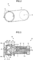
- FIG. 2 is a perspective view of a waterproof cap which is used in the endoscope system illustrated in FIG. 1 .
- FIG. 3 is a cross-sectional view of an optical transmitting module which is used in the endoscope system illustrated in FIG. 1 .
- FIG. 4 is a cross-sectional view of an optical transmitting unit in which the optical transmitting module of FIG. 3 is capped by the waterproof cap of FIG. 2 .
- an optical transmitting unit 100 includes an optical transmitting module 20; an optical connector 30 connected to the optical transmitting module 20; and a waterproof cap 10 that seals an optical connecting portion between the optical connector 30 and the optical transmitting module 20 in a watertight manner.
- the optical transmitting unit 100 is disposed at the operating unit 7 or the insertion unit 6 of the endoscope 2, and transmits an optical signal which is obtained by photoelectrically converting an image signal, to the processing device 3 through an optical fiber 31 in the universal cord 8.
- the waterproof cap 10 includes a tubular main body portion 11 having a bottom, with one end open and the other end closed in a height direction; connecting portions 12 on the opening portion side which are connected to a flexible substrate 28 of the optical transmitting module 20 which will be described later; and a hole portion 13 through which the optical fiber 31 is inserted.
- the main body portion 11 has a cylindrical shape with substantially the same diameter from the opening portion to the bottom.
- the optical transmitting module 20 includes: the flexible substrate 28; a light emitting element 21 which is mounted on the flexible substrate 28 through leads 27; and a metal case 23 that stores the light emitting element 21.
- An image signal captured by the imaging unit is transmitted to the light emitting element 21 through the flexible substrate 28, and photoelectrically converted, and then exits as an optical signal from a light emitting portion 22.
- the optical signal exiting from the light emitting portion 22 is condensed by a transparent glass body 24 and a condenser lens 25.
- the metal case 23 includes a sleeve 26 into which a ferrule 32 of the optical connector 30 which will be described later is inserted.
- the flexible substrate 28 is provided with hole portions 28a into which the connecting portions 12 of the waterproof cap 10 are inserted.
- connection portions 12 By inserting the connecting portions 12 into the hole portions 28a to connect the waterproof cap 10 to the flexible substrate 28, the strength of a connecting portion between the flexible substrate 28 and the light emitting element 21 through the leads 27 can be improved. Fixation between the connecting portions 12 and the hole portions 28a may be done by press-fitting the connecting portions 12 which are formed to be larger in diameter than the hole portions 28a or, in addition to that, the connecting portions 12 and the hole portions 28a may be fixed by bonding with an adhesive or the like.
- the optical connector 30 includes the ferrule 32 that holds the optical fiber 31; and a flange portion 33 provided at one end of the ferrule 32.
- a small hole 32a is provided to pass through the center in an axial direction of the cylindrical shape.
- the optical connector 30 holds the optical fiber 31.
- an end face of the optical fiber 31 that is inserted through the small hole 32a and that is exposed to an end face of the ferrule 32 on a side inserted into the sleeve 26 (hereinafter, referred to as "distal end portion") is polished in order to reduce loss in the amount of light at the optical connecting portion.
- the flange portion 33 having a columnar shape concentric with the ferrule 32 is provided at an outer portion of the ferrule 32 on the opposite side of the distal end portion of the ferrule 32 (hereinafter, referred to as "proximal end portion").
- a plurality of step portions 23a, 23b, 23c, 23d, 23e, 23f, and 23g are formed on an outer portion of a portion of the metal case 23 where the light emitting element 21 is accommodated.
- the step portions 23a, 23b, 23c, 23d, 23e, 23f, and 23g form concentric shapes.
- the optical connecting portion between the optical transmitting module 20 and the optical connector 30, i.e., the step portion 23a that is the closest step portion to an optical connecting portion C between the condenser lens 25 and the ferrule 32, is formed to be larger in outside diameter than the other step portions 23b, 23c, 23d, 23e, 23f, and 23g. As illustrated in FIG.
- the step portion 23a having the largest outside diameter contacts the inner surface of the waterproof cap 10 along an entire circumference thereof, and functions as waterproof means for ensuring the water-tightness of the optical connecting portion C.
- a gap between the optical fiber 31 and the hole portion 13 through which the optical fiber 31 is inserted be filled with an adhesive or the like.
- a thermoplastic material or a material that is softened by ultraviolet radiation may be used as a material for the waterproof cap 10 or a covering of the optical fiber 31, and an area around the hole portion 13 may be heated or subjected to ultraviolet irradiation for melt fixation.
- the step portion 23a that is the closest to the optical connecting portion C between the condenser lens 25 and the ferrule 32 functions as waterproof means
- even a step portion that is not close to the optical connecting portion C functions as waterproof means by allowing the step portion to have the largest diameter.
- the outside diameter of the metal case 23 be as small as possible, and it is difficult, in terms of design, to increase the difference in outside diameter between the step portions 23a, 23b, 23c, 23d, 23e, 23f, and 23g.
- the step portion 23a closest to the optical connecting portion C has the largest diameter so as to contact the inner surface of the waterproof cap 10 along an entire circumference thereof, and thereby serves as waterproof means for ensuring water-tightness.
- optical transmitting unit 100 and the endoscope system 1 including the optical transmitting unit 100 are described, in an optical receiving unit, too, that converts an optical signal into an electrical signal and that is disposed at any of the components of the endoscope system 1, by allowing the optical receiving unit to have the same configuration as the optical transmitting unit 100, the water-tightness of an optical connecting portion can be ensured.
- the cylindrically shaped waterproof cap 10 having substantially the same diameter from an opening portion to a bottom
- the configuration is not limited thereto.
- a tapered shape whose diameter increases in a direction of an opening portion from a bottom may be employed. By increasing the diameter of the opening portion side, the likelihood of contact between the step portions 23b to 23g other than the step portion 23a serving as waterproof means and the waterproof cap 10 can be reduced.
- the waterproof cap 10 may be tapered all the way from a bottom to an opening portion; however, it is preferred to employ a cylindrical shape with the same diameter from a bottom to near a contact portion with the step portion 23a serving as waterproof means, and a tapered shape for the rest.
- FIG. 5 is a cross-sectional view of an optical transmitting unit according to a second embodiment of the present invention.
- waterproof means differs from the one in the first embodiment in that the waterproof means includes: a groove portion 29 formed by three continuous step portions 23a to 23c that are the closest step portions to an optical connecting portion C; and an O-ring 35 provided in the groove portion 29.
- the outside diameter of the O-ring 35 provided in the groove portion 29 be larger than the inside diameter of a waterproof cap 10 and the outside diameters of other step portions 23a to 23g. Since the outside diameter of the O-ring 35 is larger than the inside diameter of the waterproof cap 10 and the outside diameters of the other step portions 23a to 23g, only the O-ring 35 contacts an inner surface of the waterproof cap 10, and thereby to ensure the water-tightness of the optical connecting portion C.
- the waterproof cap 10 may have a cylindrical shape with substantially the same diameter from an opening portion to a bottom, or may have a tapered shape whose diameter increases in a direction of an opening portion from a bottom.
- an optical receiving unit too, that converts an optical signal into an electrical signal and that is disposed at any of the components of an endoscope system 1, as with the optical transmitting unit 100A, by forming waterproof means by a groove portion composed of three continuous step portions that are the closest step portions from an optical connecting portion; and an O-ring provided in the groove portion, the water-tightness of the optical connecting portion can be ensured.
- FIG. 6 is a diagram illustrating a waterproof cap according to a third embodiment of the present invention.
- a waterproof cap 10B is formed by combining two main body portions 11a and 11b which are divided in a height direction.
- an optical transmitting module and an optical connector which are connected to each other are capped by the main body portions 11a and 11b in upper and lower directions, and end faces are bonded with an adhesive.
- the main body portions 11a and 11b may be formed of a thermoplastic material or a material that is softened by ultraviolet radiation, and connecting portions may be heated or subjected to ultraviolet irradiation for melt connection. Since the waterproof cap 10B is formed by the two divided main body portions 11a and 11b, even when the optical transmitting module and the optical connector are being attached to each other, placement of the waterproof cap is facilitated.
- an optical transmitting module 20 in which the closest step portion from an optical connecting portion C is used as waterproof means, or an optical transmitting module 20A (second embodiment) whose waterproof means is formed from a groove portion composed of three continuous step portions that are the closest step portions from an optical connecting portion C; and an O-ring provided in the groove portion, by the main body portions 11a and 11b and connecting the main body portions 11a and 11b together, the water-tightness of the optical connecting portion C can be ensured.
Landscapes
- Physics & Mathematics (AREA)
- Optics & Photonics (AREA)
- Health & Medical Sciences (AREA)
- Life Sciences & Earth Sciences (AREA)
- Engineering & Computer Science (AREA)
- Surgery (AREA)
- General Physics & Mathematics (AREA)
- Electromagnetism (AREA)
- Signal Processing (AREA)
- Computer Networks & Wireless Communication (AREA)
- Pathology (AREA)
- Veterinary Medicine (AREA)
- Medical Informatics (AREA)
- Molecular Biology (AREA)
- Animal Behavior & Ethology (AREA)
- General Health & Medical Sciences (AREA)
- Public Health (AREA)
- Heart & Thoracic Surgery (AREA)
- Biomedical Technology (AREA)
- Radiology & Medical Imaging (AREA)
- Nuclear Medicine, Radiotherapy & Molecular Imaging (AREA)
- Biophysics (AREA)
- Astronomy & Astrophysics (AREA)
- Endoscopes (AREA)
- Instruments For Viewing The Inside Of Hollow Bodies (AREA)
Abstract
Description
- The present invention relates to an optical transmitting and receiving unit with excellent waterproof properties.
- Conventionally, in the medical field, an endoscope system is used when the internal organs of a subject such as a patient are observed. The endoscope system includes, for example, an endoscope having an insertion unit that is provided with an image sensor at its distal end, has a flexible elongated shape, and is inserted into a subject's body cavity; and a processing device that is connected to the insertion unit through a cable or a connector to perform image processing of an in-vivo image captured by the image sensor, and displays the in-vivo image on a display device.
- In recent years, an image sensor with a large number of pixels that allows observation of clearer images has been developed, and use of the image sensor with a large number of pixels in an endoscope has been considered. In addition, in consideration of ease of insertion into a subject's body, a reduction in the diameter of the insertion unit is sought. Furthermore, in order to transmit large-volume signals at high speed between the image sensor and the processing device while achieving a reduction in the diameter of the insertion unit, an optical transmitting and receiving unit that transmits signals using an optical fiber is also adopted in the endoscope system.
- In the optical transmitting and receiving unit using an optical fiber, if contamination is attached to a distal end face of the optical fiber, there is a possibility of optical loss. Accordingly, there are disclosed an optical fiber connector cap that cleans the distal end face of the optical fiber and an optical fiber connector cap that prevents the adhesion of contamination (see, for example,
Patent Literatures 1 and 2). -
- Patent Literature 1: Japanese Patent Application Laid-open No.
2010-117440 - Patent Literature 2: Japanese Patent Application Laid-open No.
2010-117443 - In the waterproof caps of
Patent Literatures - The present invention has been made in view of the foregoing, and an object of the invention is to provide an optical transmitting and receiving unit and an endoscope system that are capable of making an optical connecting portion waterproof even when a device having the unit is, for example, damaged caused by use of the device.
- In order to solve the above described problems and achieve the object, an optical transmitting and receiving unit according to the invention includes: an optical transmitting and receiving module having a light emitting element or a light receiving element and having a metal case that stores the light emitting element or the light receiving element; an optical connector having a ferrule for holding an optical fiber and having a flange portion provided at one end of the ferrule, the ferrule being inserted into a sleeve of the metal case to connect the optical connector with the optical transmitting and receiving module; and a tubular waterproof cap that has a bottom, with one end open and the other end closed, and caps the optical connector to seal an optical connecting portion between the optical connector and the optical transmitting and receiving module in a watertight manner. The metal case has a plurality of step portions with different outside diameters. One of the plurality of step portions closest to the optical connecting portion contacts an inner surface of the waterproof cap along an entire circumference thereof.
- In the optical transmitting and receiving unit according to the above-described invention, an outside diameter of the one of the plurality of step portions closest to the optical connecting portion is larger than outside diameters of the other of the plurality of step portions and larger than an inside diameter of the waterproof cap.
- An optical transmitting and receiving unit according to the invention includes: an optical transmitting and receiving module having a light emitting element or a light receiving element and having a metal case that stores the light emitting element or the light receiving element; an optical connector having a ferrule for holding an optical fiber and having a flange portion provided at one end of the ferrule, the ferrule being inserted into a sleeve of the metal case to connect the optical connector with the optical transmitting and receiving module; and a tubular waterproof cap that has a bottom, with one end open and the other end closed, and caps the optical connector to seal an optical connecting portion between the optical connector and the optical transmitting and receiving module in a watertight manner. The metal case has a plurality of step portions with different outside diameters. An O-ring is provided in a groove portion closest to the optical connecting portion. The O-ring contacts an inner surface of the waterproof cap along an entire circumference thereof.
- In the optical transmitting and receiving unit according to the above-described invention, an outside diameter of the O-ring is larger than an inside diameter of the waterproof cap and outside diameters of other plurality of step portions.
- In the optical transmitting and receiving unit according to the above-described invention, the waterproof cap has a connecting portion to a substrate to be connected on a side of the open end of the waterproof cap.
- In the optical transmitting and receiving unit according to the above-described invention, the waterproof cap is a combination of two main body portions divided in a height direction of the waterproof cap.
- According to the present invention, a metal case has a plurality of step portions with different outside diameters, one of the plurality of step portions closest to an optical connecting portion has the largest diameter, and the one of the plurality of step portions closest to the optical connecting portion is brought into contact with an inner surface of a waterproof cap covering the optical connecting portion along an entire circumference. With this configuration, even when an optical transmitting and receiving unit is used in an endoscope or the like and the endoscope is damaged, the water-tightness of the optical connecting portion can be ensured.
-
-
FIG. 1 is a schematic diagram illustrating a configuration of an endoscope system according to a first embodiment of the present invention. -
FIG. 2 is a perspective view of a waterproof cap which is used in the endoscope system illustrated inFIG. 1 . -
FIG. 3 is a cross-sectional view of an optical transmitting module which is used in the endoscope system illustrated inFIG. 1 . -
FIG. 4 is a cross-sectional view of an optical transmitting unit in which the optical transmitting module ofFIG. 3 is capped by the waterproof cap ofFIG. 2 . -
FIG. 5 is a cross-sectional view of an optical transmitting unit according to a second embodiment of the present invention. -
FIG. 6 is a diagram illustrating a waterproof cap according to a third embodiment of the present invention. Description of Embodiments - As modes for carrying out the present invention (hereinafter, referred to as "embodiment(s)"), endoscope systems will be described below. The invention is not to be limited by the embodiments. The same reference signs are used to designate the same elements throughout the drawings.
-
FIG. 1 is a schematic diagram illustrating a configuration of an endoscope system according to embodiments of the present invention. As illustrated inFIG. 1 , anendoscope system 1 according to the embodiments includes: anendoscope 2 that is configured to be inserted into a subject's body to image the inside of the subject's body and generate an image signal of the inside of the subject's body; aprocessing device 3 that is configured to perform predetermined image processing on the image signal generated by theendoscope 2, and to control each element of theendoscope system 1; alight source device 4 that is configured to generate illumination light for theendoscope 2; and adisplay device 5 that is configured to display, as an image, the image signal having been subjected to the image processing by theprocessing device 3. - The
endoscope 2 includes aninsertion unit 6 which is inserted into the subject's body; anoperating unit 7 which is on the proximal end portion side of theinsertion unit 6 and which is held by an operator; and a flexibleuniversal cord 8 extending from theoperating unit 7. - The
insertion unit 6 is implemented by an illumination fiber (light guide cable), an electrical cable, an optical fiber, and the like. Theinsertion unit 6 includes: adistal end portion 6a having an imaging unit including an image sensor to image the inside of the subject's body; abendable bending portion 6b formed by a plurality of bending pieces; and aflexible tube portion 6c having flexibility and provided on the side of the proximal end portion of thebending portion 6b. Thedistal end portion 6a includes: an illumination unit configured to illuminate the inside of the subject's body through an illumination lens; an observation unit configured to image the inside of the subject's body; anopening portion 6d communicating with a processing tool channel; and an air and water supply nozzle (not illustrated). - The
operating unit 7 includes abend knob 7a that allows thebending portion 6b to bend in an up-down direction and a left-right direction; a treatmenttool insertion unit 7b into which a treatment tool, such as biopsy forceps or a laser knife which is inserted into a subject's body cavity, is configured to be inserted; and a plurality ofswitch units 7c that operate peripheral devices such as theprocessing device 3, thelight source device 4, an air supply device, a water supply device, and a gas supply device. A treatment tool is inserted into the treatmenttool insertion unit 7b and comes out of theopening portion 6d at a distal end of theinsertion unit 6 through the treatment tool channel provided inside. - The
universal cord 8 is formed using an illumination fiber, an electrical cable, an optical fiber, and the like. Theuniversal cord 8 is branched at its proximal end, and one of the branched end portions is aconnector 8a and the other proximal end is aconnector 8b. Theconnector 8a is removable from aconnector 3a of theprocessing device 3. Theconnector 8b is removable from thelight source device 4. Theuniversal cord 8 propagates illumination light exiting from thelight source device 4 to thedistal end portion 6a through theconnector 8b, theoperating unit 7, and theflexible tube portion 6c. Theuniversal cord 8 transmits an image signal captured by the imaging unit included in thedistal end portion 6a, to theprocessing device 3 by an optical transmitting unit which will be described later. - The
processing device 3 performs predetermined image processing on the image signal of the inside of the subject's body which is captured by the imaging unit included in thedistal end portion 6a of theendoscope 2. Theprocessing device 3 controls the components of theendoscope system 1, based on various types of instruction signals which are transmitted through theuniversal cord 8 from theswitch units 7c included in theoperating unit 7 of theendoscope 2. - The
light source device 4 is formed using a light source that emits light, a condenser lens, etc. Under control of theprocessing device 3, thelight source device 4 emits light from the light source and supplies the light to theendoscope 2 connected thereto through theconnector 8b and the illumination fiber of theuniversal cord 8, as illumination light for the inside of the subject's body which is a subject for imaging. - The
display device 5 is formed using, for example, a display using liquid crystal or an organic EL (Electro Luminescence). Thedisplay device 5 displays various types of information including the image having been subjected to the predetermined image processing by theprocessing device 3, through animage cable 5a. Thus, the operator can observe a desired position of the inside of the subject's body and determine properties by operating theendoscope 2 while viewing the image (in-vivo image) displayed on thedisplay device 5. - Next, reference will be made to an optical transmitting unit that transmits the image signal captured by the imaging unit in the
endoscope 2 illustrated inFIG. 1 to the processing device.FIG. 2 is a perspective view of a waterproof cap which is used in the endoscope system illustrated inFIG. 1 .FIG. 3 is a cross-sectional view of an optical transmitting module which is used in the endoscope system illustrated inFIG. 1 .FIG. 4 is a cross-sectional view of an optical transmitting unit in which the optical transmitting module ofFIG. 3 is capped by the waterproof cap ofFIG. 2 . - In the first embodiment, an
optical transmitting unit 100 includes anoptical transmitting module 20; anoptical connector 30 connected to theoptical transmitting module 20; and awaterproof cap 10 that seals an optical connecting portion between theoptical connector 30 and theoptical transmitting module 20 in a watertight manner. Theoptical transmitting unit 100 is disposed at theoperating unit 7 or theinsertion unit 6 of theendoscope 2, and transmits an optical signal which is obtained by photoelectrically converting an image signal, to theprocessing device 3 through anoptical fiber 31 in theuniversal cord 8. - As illustrated in
FIG. 2 , thewaterproof cap 10 includes a tubularmain body portion 11 having a bottom, with one end open and the other end closed in a height direction; connectingportions 12 on the opening portion side which are connected to aflexible substrate 28 of theoptical transmitting module 20 which will be described later; and ahole portion 13 through which theoptical fiber 31 is inserted. Themain body portion 11 has a cylindrical shape with substantially the same diameter from the opening portion to the bottom. - The
optical transmitting module 20 includes: theflexible substrate 28; alight emitting element 21 which is mounted on theflexible substrate 28 throughleads 27; and ametal case 23 that stores thelight emitting element 21. An image signal captured by the imaging unit is transmitted to thelight emitting element 21 through theflexible substrate 28, and photoelectrically converted, and then exits as an optical signal from alight emitting portion 22. The optical signal exiting from thelight emitting portion 22 is condensed by atransparent glass body 24 and acondenser lens 25. Themetal case 23 includes asleeve 26 into which aferrule 32 of theoptical connector 30 which will be described later is inserted. In addition, theflexible substrate 28 is provided withhole portions 28a into which the connectingportions 12 of thewaterproof cap 10 are inserted. By inserting the connectingportions 12 into thehole portions 28a to connect thewaterproof cap 10 to theflexible substrate 28, the strength of a connecting portion between theflexible substrate 28 and thelight emitting element 21 through theleads 27 can be improved. Fixation between the connectingportions 12 and thehole portions 28a may be done by press-fitting the connectingportions 12 which are formed to be larger in diameter than thehole portions 28a or, in addition to that, the connectingportions 12 and thehole portions 28a may be fixed by bonding with an adhesive or the like. - The
optical connector 30 includes theferrule 32 that holds theoptical fiber 31; and aflange portion 33 provided at one end of theferrule 32. In the substantiallycylindrical ferrule 32, asmall hole 32a is provided to pass through the center in an axial direction of the cylindrical shape. By inserting theoptical fiber 31 through thesmall hole 32a, theoptical connector 30 holds theoptical fiber 31. In this description, an end face of theoptical fiber 31 that is inserted through thesmall hole 32a and that is exposed to an end face of theferrule 32 on a side inserted into the sleeve 26 (hereinafter, referred to as "distal end portion") is polished in order to reduce loss in the amount of light at the optical connecting portion. Theflange portion 33 having a columnar shape concentric with theferrule 32 is provided at an outer portion of theferrule 32 on the opposite side of the distal end portion of the ferrule 32 (hereinafter, referred to as "proximal end portion"). - A plurality of
step portions metal case 23 where thelight emitting element 21 is accommodated. Thestep portions optical transmitting module 20 and theoptical connector 30, i.e., thestep portion 23a that is the closest step portion to an optical connecting portion C between thecondenser lens 25 and theferrule 32, is formed to be larger in outside diameter than theother step portions FIG. 4 , thestep portion 23a having the largest outside diameter contacts the inner surface of thewaterproof cap 10 along an entire circumference thereof, and functions as waterproof means for ensuring the water-tightness of the optical connecting portion C. In addition, in order to ensure the water-tightness of the optical connecting portion C, it is preferred that a gap between theoptical fiber 31 and thehole portion 13 through which theoptical fiber 31 is inserted be filled with an adhesive or the like. Alternatively, without using an adhesive, a thermoplastic material or a material that is softened by ultraviolet radiation may be used as a material for thewaterproof cap 10 or a covering of theoptical fiber 31, and an area around thehole portion 13 may be heated or subjected to ultraviolet irradiation for melt fixation. - Although in the first embodiment the
step portion 23a that is the closest to the optical connecting portion C between thecondenser lens 25 and theferrule 32 functions as waterproof means, even a step portion that is not close to the optical connecting portion C functions as waterproof means by allowing the step portion to have the largest diameter. However, when theoptical transmitting unit 100 is used in theendoscope 2, it is preferred that the outside diameter of themetal case 23 be as small as possible, and it is difficult, in terms of design, to increase the difference in outside diameter between thestep portions step portions 23a to 23g, water-tightness may not be able to be ensured due to contact of other step portions with thewaterproof cap 10. Therefore, thestep portion 23a closest to the optical connecting portion C has the largest diameter so as to contact the inner surface of thewaterproof cap 10 along an entire circumference thereof, and thereby serves as waterproof means for ensuring water-tightness. With this configuration, the water-tightness of the optical connecting portion C can be securely ensured while suppressing an increase in the size of themetal case 23. - Although in the first embodiment the
optical transmitting unit 100 and theendoscope system 1 including theoptical transmitting unit 100 are described, in an optical receiving unit, too, that converts an optical signal into an electrical signal and that is disposed at any of the components of theendoscope system 1, by allowing the optical receiving unit to have the same configuration as theoptical transmitting unit 100, the water-tightness of an optical connecting portion can be ensured. - In addition, although in the first embodiment, the cylindrically shaped
waterproof cap 10 having substantially the same diameter from an opening portion to a bottom is used, the configuration is not limited thereto. A tapered shape whose diameter increases in a direction of an opening portion from a bottom may be employed. By increasing the diameter of the opening portion side, the likelihood of contact between thestep portions 23b to 23g other than thestep portion 23a serving as waterproof means and thewaterproof cap 10 can be reduced. Thewaterproof cap 10 may be tapered all the way from a bottom to an opening portion; however, it is preferred to employ a cylindrical shape with the same diameter from a bottom to near a contact portion with thestep portion 23a serving as waterproof means, and a tapered shape for the rest. -
FIG. 5 is a cross-sectional view of an optical transmitting unit according to a second embodiment of the present invention. In anoptical transmitting unit 100A according to the second embodiment, waterproof means differs from the one in the first embodiment in that the waterproof means includes: agroove portion 29 formed by threecontinuous step portions 23a to 23c that are the closest step portions to an optical connecting portion C; and an O-ring 35 provided in thegroove portion 29. - It is preferred that the outside diameter of the O-
ring 35 provided in thegroove portion 29 be larger than the inside diameter of awaterproof cap 10 and the outside diameters ofother step portions 23a to 23g. Since the outside diameter of the O-ring 35 is larger than the inside diameter of thewaterproof cap 10 and the outside diameters of theother step portions 23a to 23g, only the O-ring 35 contacts an inner surface of thewaterproof cap 10, and thereby to ensure the water-tightness of the optical connecting portion C. - In the
optical transmitting unit 100A of the second embodiment, thewaterproof cap 10 may have a cylindrical shape with substantially the same diameter from an opening portion to a bottom, or may have a tapered shape whose diameter increases in a direction of an opening portion from a bottom. In addition, in an optical receiving unit, too, that converts an optical signal into an electrical signal and that is disposed at any of the components of anendoscope system 1, as with theoptical transmitting unit 100A, by forming waterproof means by a groove portion composed of three continuous step portions that are the closest step portions from an optical connecting portion; and an O-ring provided in the groove portion, the water-tightness of the optical connecting portion can be ensured. -
FIG. 6 is a diagram illustrating a waterproof cap according to a third embodiment of the present invention. In the third embodiment, awaterproof cap 10B is formed by combining twomain body portions - In the
waterproof cap 10B, an optical transmitting module and an optical connector which are connected to each other are capped by themain body portions main body portions waterproof cap 10B is formed by the two dividedmain body portions - In the third embodiment, by covering an optical transmitting module 20 (first embodiment) in which the closest step portion from an optical connecting portion C is used as waterproof means, or an
optical transmitting module 20A (second embodiment) whose waterproof means is formed from a groove portion composed of three continuous step portions that are the closest step portions from an optical connecting portion C; and an O-ring provided in the groove portion, by themain body portions main body portions -
- 1
- ENDOSCOPE SYSTEM
- 2
- ENDOSCOPE
- 3
- PROCESSING DEVICE
- 4
- LIGHT SOURCE DEVICE
- 5
- DISPLAY DEVICE
- 6
- INSERTION UNIT
- 6a
- DISTAL END PORTION
- 6b
- BENDING PORTION
- 6c
- FLEXIBLE TUBE PORTION
- 6d
- OPENING PORTION
- 7
- OPERATING UNIT
- 7a
- BEND KNOB
- 7b
- TREATMENT TOOL INSERTION UNIT
- 7c
- SWITCH UNIT
- 8
- UNIVERSAL CORD
- 8a, 8b
- CONNECTOR
- 10, 10B
- WATERPROOF CAP
- 11, 11a, 11b
- MAIN BODY PORTION
- 12
- CONNECTING PORTION
- 13
- HOLE PORTION
- 20,
- 20A OPTICAL TRANSMITTING MODULE
- 21
- LIGHT EMITTING ELEMENT
- 22
- LIGHT EMITTING PORTION
- 23
- METAL CASE
- 23a, 23b, 23c, 23d, 23e, 23f, 23g
- STEP PORTION
- 24
- TRANSPARENT GLASS BODY
- 25
- CONDENSER LENS
- 26
- SLEEVE
- 27
- LEAD
- 28
- FLEXIBLE SUBSTRATE
- 29
- GROOVE PORTION
- 30
- OPTICAL CONNECTOR
- 31
- OPTICAL FIBER
- 32
- FERRULE
- 32a
- SMALL HOLE
- 33
- FLANGE PORTION
- 35
- O-RING
- 100, 100A
- OPTICAL TRANSMITTING UNIT
Claims (6)
- An optical transmitting and receiving unit comprising:an optical transmitting and receiving module having a light emitting element or a light receiving element and having a metal case that stores the light emitting element or the light receiving element;an optical connector having a ferrule for holding an optical fiber and having a flange portion provided at one end of the ferrule, the ferrule being inserted into a sleeve of the metal case to connect the optical connector with the optical transmitting and receiving module; anda tubular waterproof cap that has a bottom, with one end open and the other end closed, and caps the optical connector to seal an optical connecting portion between the optical connector and the optical transmitting and receiving module in a watertight manner, whereinthe metal case has a plurality of step portions with different outside diameters, andone of the plurality of step portions closest to the optical connecting portion contacts an inner surface of the waterproof cap along an entire circumference thereof.
- The optical transmitting and receiving unit according to claim 1, wherein an outside diameter of the one of the plurality of step portions closest to the optical connecting portion is larger than outside diameters of the other of the plurality of step portions and larger than an inside diameter of the waterproof cap.
- An optical transmitting and receiving unit comprising:an optical transmitting and receiving module having a light emitting element or a light receiving element and having a metal case that stores the light emitting element or the light receiving element;an optical connector having a ferrule for holding an optical fiber and having a flange portion provided at one end of the ferrule, the ferrule being inserted into a sleeve of the metal case to connect the optical connector with the optical transmitting and receiving module; anda tubular waterproof cap that has a bottom, with one end open and the other end closed, and caps the optical connector to seal an optical connecting portion between the optical connector and the optical transmitting and receiving module in a watertight manner, whereinthe metal case has a plurality of step portions with different outside diameters,an O-ring is provided in a groove portion closest to the optical connecting portion, andthe O-ring contacts an inner surface of the waterproof cap along an entire circumference thereof.
- The optical transmitting and receiving unit according to claim 3, wherein an outside diameter of the O-ring is larger than an inside diameter of the waterproof cap and outside diameters of other plurality of step portions.
- The optical transmitting and receiving unit according to any one of claims 1 to 4, wherein the waterproof cap has a connecting portion to a substrate to be connected on a side of the open end of the waterproof cap.
- The optical transmitting and receiving unit according to any one of claims 1 to 5, wherein the waterproof cap is a combination of two main body portions divided in a height direction of the waterproof cap.
Applications Claiming Priority (2)
| Application Number | Priority Date | Filing Date | Title |
|---|---|---|---|
| JP2014195230 | 2014-09-25 | ||
| PCT/JP2015/058123 WO2016047172A1 (en) | 2014-09-25 | 2015-03-18 | Optical transmitter/receiver unit |
Publications (2)
| Publication Number | Publication Date |
|---|---|
| EP3199093A1 true EP3199093A1 (en) | 2017-08-02 |
| EP3199093A4 EP3199093A4 (en) | 2018-06-06 |
Family
ID=55580714
Family Applications (1)
| Application Number | Title | Priority Date | Filing Date |
|---|---|---|---|
| EP15843467.0A Withdrawn EP3199093A4 (en) | 2014-09-25 | 2015-03-18 | Optical transmitter/receiver unit |
Country Status (5)
| Country | Link |
|---|---|
| US (1) | US9537574B2 (en) |
| EP (1) | EP3199093A4 (en) |
| JP (1) | JP5851661B1 (en) |
| CN (1) | CN105636498B (en) |
| WO (1) | WO2016047172A1 (en) |
Cited By (2)
| Publication number | Priority date | Publication date | Assignee | Title |
|---|---|---|---|---|
| US11464392B2 (en) | 2017-09-25 | 2022-10-11 | Olympus Corporation | Optical module and endoscope |
| US12274415B2 (en) | 2020-02-04 | 2025-04-15 | Olympus Corporation | Endoscope apparatus for transmitting an endoscope image as an optical signal |
Family Cites Families (14)
| Publication number | Priority date | Publication date | Assignee | Title |
|---|---|---|---|---|
| JP2533360B2 (en) * | 1988-07-22 | 1996-09-11 | 松下電器産業株式会社 | Luminous module |
| JP2902882B2 (en) * | 1992-12-14 | 1999-06-07 | 三洋電機株式会社 | Semiconductor laser device with optical connector |
| JP2000047066A (en) * | 1998-07-31 | 2000-02-18 | Digital Electronics Corp | Environmental resistance connector structure |
| JP4285029B2 (en) * | 2003-02-28 | 2009-06-24 | 住友電気工業株式会社 | Ferrule with optical fiber and optical module |
| KR100566256B1 (en) * | 2004-02-13 | 2006-03-29 | 삼성전자주식회사 | Bidirectional Optical Transmission Module |
| JP2007304266A (en) * | 2006-05-10 | 2007-11-22 | Fuji Xerox Co Ltd | Optical module and optical communication system |
| JP2008011504A (en) * | 2006-05-29 | 2008-01-17 | Pentax Corp | Optical signal transmitter / receiver |
| JP2008170636A (en) * | 2007-01-10 | 2008-07-24 | Nec Electronics Corp | Semiconductor laser module |
| JP2010109173A (en) * | 2008-10-30 | 2010-05-13 | Mitsubishi Electric Corp | Optical transmitter-receiver, optical transmitter and optical receiver |
| JP2010117443A (en) | 2008-11-11 | 2010-05-27 | Hoya Corp | Optical fiber connector cap |
| JP2010117440A (en) * | 2008-11-11 | 2010-05-27 | Hoya Corp | Cap for optical fiber connector |
| JP2012054466A (en) * | 2010-09-02 | 2012-03-15 | Renesas Electronics Corp | Optical transmitter module and method for manufacturing the same |
| JP5707808B2 (en) * | 2010-09-21 | 2015-04-30 | 富士通株式会社 | Coupling device |
| WO2012153940A2 (en) * | 2011-05-10 | 2012-11-15 | 주식회사 옵토웰 | Multi -wavelength optical transmitter module using vcsel, optical transceiver module and bidirectional optical transceiver |
-
2015
- 2015-03-18 CN CN201580002045.5A patent/CN105636498B/en active Active
- 2015-03-18 EP EP15843467.0A patent/EP3199093A4/en not_active Withdrawn
- 2015-03-18 JP JP2015538172A patent/JP5851661B1/en active Active
- 2015-03-18 WO PCT/JP2015/058123 patent/WO2016047172A1/en not_active Ceased
-
2016
- 2016-03-31 US US15/086,553 patent/US9537574B2/en active Active
Cited By (2)
| Publication number | Priority date | Publication date | Assignee | Title |
|---|---|---|---|---|
| US11464392B2 (en) | 2017-09-25 | 2022-10-11 | Olympus Corporation | Optical module and endoscope |
| US12274415B2 (en) | 2020-02-04 | 2025-04-15 | Olympus Corporation | Endoscope apparatus for transmitting an endoscope image as an optical signal |
Also Published As
| Publication number | Publication date |
|---|---|
| US20160211919A1 (en) | 2016-07-21 |
| CN105636498A (en) | 2016-06-01 |
| JP5851661B1 (en) | 2016-02-03 |
| US9537574B2 (en) | 2017-01-03 |
| JPWO2016047172A1 (en) | 2017-04-27 |
| EP3199093A4 (en) | 2018-06-06 |
| WO2016047172A1 (en) | 2016-03-31 |
| CN105636498B (en) | 2017-09-26 |
Similar Documents
| Publication | Publication Date | Title |
|---|---|---|
| US9261662B2 (en) | Photoelectric conversion connector, optical transmission module, imaging apparatus, and endoscope | |
| US20130172676A1 (en) | Multi-camera endoscope having fluid channels | |
| EP3207852B1 (en) | Resin distal end component for endoscope | |
| US11432797B2 (en) | Ultrasound endoscope and ultrasound endoscope system | |
| US10463231B2 (en) | Endoscope | |
| JP2013123647A (en) | Endoscope with removable distal end | |
| US11125990B2 (en) | Endoscope distal end portion, endoscope, and method of manufacturing endoscope distal end portion | |
| CN107529967B (en) | Endoscope system | |
| JP6062076B2 (en) | Unit, method of connecting module and connector, and endoscope system | |
| JP5872911B2 (en) | Imaging unit and imaging system | |
| US9537574B2 (en) | Optical transmitting and receiving unit | |
| EP2923631B1 (en) | Endoscope insertion portion and endoscope | |
| JP6298784B2 (en) | Endoscope | |
| JP5322448B2 (en) | Screening endoscope | |
| US20160157705A1 (en) | Endoscope | |
| WO2022230024A1 (en) | Endoscope objective optical element | |
| JP2016209084A (en) | Endoscope system | |
| JP2016158803A (en) | Arthroscopic device |
Legal Events
| Date | Code | Title | Description |
|---|---|---|---|
| STAA | Information on the status of an ep patent application or granted ep patent |
Free format text: STATUS: THE INTERNATIONAL PUBLICATION HAS BEEN MADE |
|
| PUAI | Public reference made under article 153(3) epc to a published international application that has entered the european phase |
Free format text: ORIGINAL CODE: 0009012 |
|
| STAA | Information on the status of an ep patent application or granted ep patent |
Free format text: STATUS: REQUEST FOR EXAMINATION WAS MADE |
|
| 17P | Request for examination filed |
Effective date: 20170411 |
|
| AK | Designated contracting states |
Kind code of ref document: A1 Designated state(s): AL AT BE BG CH CY CZ DE DK EE ES FI FR GB GR HR HU IE IS IT LI LT LU LV MC MK MT NL NO PL PT RO RS SE SI SK SM TR |
|
| AX | Request for extension of the european patent |
Extension state: BA ME |
|
| DAV | Request for validation of the european patent (deleted) | ||
| DAX | Request for extension of the european patent (deleted) | ||
| A4 | Supplementary search report drawn up and despatched |
Effective date: 20180509 |
|
| RIC1 | Information provided on ipc code assigned before grant |
Ipc: G02B 6/42 20060101ALI20180503BHEP Ipc: H04B 10/25 20130101ALI20180503BHEP Ipc: A61B 1/00 20060101AFI20180503BHEP Ipc: G02B 23/24 20060101ALI20180503BHEP Ipc: H04B 10/80 20130101ALI20180503BHEP |
|
| STAA | Information on the status of an ep patent application or granted ep patent |
Free format text: STATUS: THE APPLICATION IS DEEMED TO BE WITHDRAWN |
|
| 18D | Application deemed to be withdrawn |
Effective date: 20181002 |