EP3199085A1 - Tomographic image formation device and control method - Google Patents
Tomographic image formation device and control method Download PDFInfo
- Publication number
- EP3199085A1 EP3199085A1 EP15843233.6A EP15843233A EP3199085A1 EP 3199085 A1 EP3199085 A1 EP 3199085A1 EP 15843233 A EP15843233 A EP 15843233A EP 3199085 A1 EP3199085 A1 EP 3199085A1
- Authority
- EP
- European Patent Office
- Prior art keywords
- image
- light
- forming apparatus
- axis
- tomographic image
- Prior art date
- Legal status (The legal status is an assumption and is not a legal conclusion. Google has not performed a legal analysis and makes no representation as to the accuracy of the status listed.)
- Granted
Links
Images




Classifications
-
- A—HUMAN NECESSITIES
- A61—MEDICAL OR VETERINARY SCIENCE; HYGIENE
- A61B—DIAGNOSIS; SURGERY; IDENTIFICATION
- A61B5/00—Measuring for diagnostic purposes; Identification of persons
- A61B5/72—Signal processing specially adapted for physiological signals or for diagnostic purposes
- A61B5/7203—Signal processing specially adapted for physiological signals or for diagnostic purposes for noise prevention, reduction or removal
- A61B5/7207—Signal processing specially adapted for physiological signals or for diagnostic purposes for noise prevention, reduction or removal of noise induced by motion artifacts
-
- A—HUMAN NECESSITIES
- A61—MEDICAL OR VETERINARY SCIENCE; HYGIENE
- A61B—DIAGNOSIS; SURGERY; IDENTIFICATION
- A61B5/00—Measuring for diagnostic purposes; Identification of persons
- A61B5/72—Signal processing specially adapted for physiological signals or for diagnostic purposes
- A61B5/7225—Details of analogue processing, e.g. isolation amplifier, gain or sensitivity adjustment, filtering, baseline or drift compensation
-
- A—HUMAN NECESSITIES
- A61—MEDICAL OR VETERINARY SCIENCE; HYGIENE
- A61B—DIAGNOSIS; SURGERY; IDENTIFICATION
- A61B1/00—Instruments for performing medical examinations of the interior of cavities or tubes of the body by visual or photographical inspection, e.g. endoscopes; Illuminating arrangements therefor
-
- A—HUMAN NECESSITIES
- A61—MEDICAL OR VETERINARY SCIENCE; HYGIENE
- A61B—DIAGNOSIS; SURGERY; IDENTIFICATION
- A61B5/00—Measuring for diagnostic purposes; Identification of persons
- A61B5/0059—Measuring for diagnostic purposes; Identification of persons using light, e.g. diagnosis by transillumination, diascopy, fluorescence
- A61B5/0062—Arrangements for scanning
- A61B5/0066—Optical coherence imaging
-
- A—HUMAN NECESSITIES
- A61—MEDICAL OR VETERINARY SCIENCE; HYGIENE
- A61B—DIAGNOSIS; SURGERY; IDENTIFICATION
- A61B5/00—Measuring for diagnostic purposes; Identification of persons
- A61B5/0059—Measuring for diagnostic purposes; Identification of persons using light, e.g. diagnosis by transillumination, diascopy, fluorescence
- A61B5/0073—Measuring for diagnostic purposes; Identification of persons using light, e.g. diagnosis by transillumination, diascopy, fluorescence by tomography, i.e. reconstruction of 3D images from 2D projections
-
- A—HUMAN NECESSITIES
- A61—MEDICAL OR VETERINARY SCIENCE; HYGIENE
- A61B—DIAGNOSIS; SURGERY; IDENTIFICATION
- A61B5/00—Measuring for diagnostic purposes; Identification of persons
- A61B5/02—Detecting, measuring or recording for evaluating the cardiovascular system, e.g. pulse, heart rate, blood pressure or blood flow
- A61B5/02007—Evaluating blood vessel condition, e.g. elasticity, compliance
-
- A—HUMAN NECESSITIES
- A61—MEDICAL OR VETERINARY SCIENCE; HYGIENE
- A61B—DIAGNOSIS; SURGERY; IDENTIFICATION
- A61B5/00—Measuring for diagnostic purposes; Identification of persons
- A61B5/02—Detecting, measuring or recording for evaluating the cardiovascular system, e.g. pulse, heart rate, blood pressure or blood flow
- A61B5/026—Measuring blood flow
- A61B5/0275—Measuring blood flow using tracers, e.g. dye dilution
-
- A—HUMAN NECESSITIES
- A61—MEDICAL OR VETERINARY SCIENCE; HYGIENE
- A61B—DIAGNOSIS; SURGERY; IDENTIFICATION
- A61B5/00—Measuring for diagnostic purposes; Identification of persons
- A61B5/68—Arrangements of detecting, measuring or recording means, e.g. sensors, in relation to patient
- A61B5/6846—Arrangements of detecting, measuring or recording means, e.g. sensors, in relation to patient specially adapted to be brought in contact with an internal body part, i.e. invasive
- A61B5/6847—Arrangements of detecting, measuring or recording means, e.g. sensors, in relation to patient specially adapted to be brought in contact with an internal body part, i.e. invasive mounted on an invasive device
- A61B5/6852—Catheters
-
- A—HUMAN NECESSITIES
- A61—MEDICAL OR VETERINARY SCIENCE; HYGIENE
- A61B—DIAGNOSIS; SURGERY; IDENTIFICATION
- A61B5/00—Measuring for diagnostic purposes; Identification of persons
- A61B5/72—Signal processing specially adapted for physiological signals or for diagnostic purposes
- A61B5/7203—Signal processing specially adapted for physiological signals or for diagnostic purposes for noise prevention, reduction or removal
-
- A—HUMAN NECESSITIES
- A61—MEDICAL OR VETERINARY SCIENCE; HYGIENE
- A61B—DIAGNOSIS; SURGERY; IDENTIFICATION
- A61B5/00—Measuring for diagnostic purposes; Identification of persons
- A61B5/72—Signal processing specially adapted for physiological signals or for diagnostic purposes
- A61B5/7235—Details of waveform analysis
- A61B5/7253—Details of waveform analysis characterised by using transforms
- A61B5/7257—Details of waveform analysis characterised by using transforms using Fourier transforms
-
- A—HUMAN NECESSITIES
- A61—MEDICAL OR VETERINARY SCIENCE; HYGIENE
- A61B—DIAGNOSIS; SURGERY; IDENTIFICATION
- A61B5/00—Measuring for diagnostic purposes; Identification of persons
- A61B5/74—Details of notification to user or communication with user or patient; User input means
- A61B5/742—Details of notification to user or communication with user or patient; User input means using visual displays
-
- A—HUMAN NECESSITIES
- A61—MEDICAL OR VETERINARY SCIENCE; HYGIENE
- A61B—DIAGNOSIS; SURGERY; IDENTIFICATION
- A61B5/00—Measuring for diagnostic purposes; Identification of persons
- A61B5/74—Details of notification to user or communication with user or patient; User input means
- A61B5/7475—User input or interface means, e.g. keyboard, pointing device, joystick
-
- A—HUMAN NECESSITIES
- A61—MEDICAL OR VETERINARY SCIENCE; HYGIENE
- A61B—DIAGNOSIS; SURGERY; IDENTIFICATION
- A61B2576/00—Medical imaging apparatus involving image processing or analysis
Definitions
- the present invention relates to a tomographic image forming apparatus and a method for reducing or removing an artifact of a tomographic image obtained by using optical coherence tomography.
- OCT optical coherence tomography
- OCT provides higher resolution (resolving power) than IVUS, and that OCT is excellent for use in evaluating calcification or a thrombus.
- OCT provides higher resolution (resolving power) than IVUS, and that OCT is excellent for use in evaluating calcification or a thrombus.
- it is possible to observe an intravascular wall in detail. Accordingly, it is expected that OCT is applied to evaluation after stent treatment.
- PTL 1 Pamphlet of International Publication No. 2010/095370
- an artifact also referred to as noise
- an artifact is caused to appear on a tomographic image due to the presence of the artificial object.
- an artifact also referred to as noise
- OCT measurement light intensive reflected light (scattered light) returns. Consequently, a radial streak appears thereon.
- This artifact hinders diagnosis using the tomographic image.
- the artifact blocks a line of sight when a three-dimensionally reconstructed image is observed from the tomographic image.
- the artifact will affect a process for automatically detecting the stent strut.
- the present invention is made in view of the above-described problems, and an object thereof is to reduce or remove an artifact on a tomographic image.
- a tomographic image forming apparatus includes the following configuration. That is, there is provided a tomographic image forming apparatus which divides light output from a light source inside the apparatus into measurement light and reference light, and which generates a cross-sectional image of an imaging target based on light intensity of interference light obtained from reflected light obtained by emitting the measurement light to the imaging target and the reference light.
- the tomographic image forming apparatus includes first generation means for generating a second image by converting a first image in which line data generated based on the light intensity and having information in a direction of a first axis which serves as a depth direction of the imaging target is arranged in a direction of a second axis, into a frequency domain, first reduction means for removing or reducing an artifact by performing filtering on the second image, and second generation means for generating a third image by inversely converting the second image processed by the first reduction means, into a spatial domain.
- Fig. 1 is a view illustrating an external configuration of an imaging apparatus for diagnosis 100 according to an embodiment of the present invention, which uses OCT (in the present embodiment, SS-OCT).
- the imaging apparatus for diagnosis 100 serving as a tomographic image forming apparatus includes a probe 101, a scanner and pull-back unit 102, and an operation control device 103.
- the scanner and pull-back unit 102 and the operation control device 103 are connected to each other via a connector 105 by a cable 104 which accommodates a signal line and an optical fiber.
- the probe 101 is directly inserted into a blood vessel.
- a catheter which accommodates an imaging core is inserted into the probe 101.
- the imaging core includes an optical transceiver which continuously transmits transmitted light (measurement light) to the inside of the blood vessel and which continuously receives reflected light from the inside of the blood vessel.
- the imaging apparatus for diagnosis 100 measures a state inside the blood vessel by using the imaging core.
- the probe 101 is detachably attached to the pullback unit 102, and the pullback unit 102 drives an embedded motor, thereby regulating the imaging core inside a catheter inserted into the probe 101, when the imaging core performs an operation in an axial direction and an operation in a rotation direction inside the blood vessel.
- the pullback unit 102 acquires the reflected light received by the optical transceiver inside the imaging core, and transmits the reflected light to the operation control device 103.
- the operation control device 103 is provided with a function for inputting various setting values and a function for displaying various blood vessel images after processing optical interference data obtained by measurement.
- the reference numeral 111 represents a main body control unit.
- the main body control unit 111 generates interference light data by causing the reflected light from the imaging core to interfere with reference light obtained by separating light from a light source. Based on the interference light data, the main body control unit 111 generates the line data, and generates a tomographic image (blood vessel cross-sectional image) based on light interference through interpolation processing.
- the reference numeral 111-1 represents a printer & DVD recorder, which prints a processing result in the main body control unit 111 or stores the processing result as data.
- the reference numeral 112 represents an operation panel. A user inputs various setting values and instructions via the operation panel 112.
- the reference numeral 113 represents an LCD monitor serving as a display device. The LCD monitor 113 displays various cross-sectional images generated by the main body control unit 111.
- the reference numeral 114 represents a mouse serving as a pointing device (coordinate input device).
- FIG. 2 is a block configuration diagram of the imaging apparatus for diagnosis 100.
- SS-OCT wavelength swept OCT
- the reference numeral 201 represents a signal processing unit which performs overall control on the imaging apparatus for diagnosis, and is configured to have some circuits including a microprocessor.
- the reference numeral 210 represents a non-volatile storage device represented by a hard disk, and stores various programs or data files to be executed by the signal processing unit 201.
- the reference numeral 202 represents a memory (RAM) disposed inside the signal processing unit 201.
- the microprocessor (computer) of the signal processing unit 201 executes a program stored in the memory 202, thereby performing a tomographic image generation process including reduction / removal of an artifact (to be described later).
- the reference numeral 203 represents a wavelength swept light source, and represents a light source which repeatedly generates light having a wavelength varying within a preset range along a time axis.
- the light output from the wavelength swept light source 203 is incident on one end of a first single mode fiber 271, and is transmitted toward a distal side.
- the first single mode fiber 271 is optically coupled to a fourth single mode fiber 275 in an optical fiber coupler 272 located in an intermediate portion.
- the light output from the wavelength swept light source 203 is divided into the measurement light and the reference light.
- the reference light proceeds to the fourth single mode fiber 275.
- the light (measurement light) which is incident on the first single mode fiber 271 and which is emitted to the distal side by the optical fiber coupler 272 is guided to a second single mode fiber 273 via the connector 105.
- the other end of the second single mode fiber 273 is connected to an optical rotary joint 230 inside the pullback unit 102.
- the probe 101 has an adapter 101a for being connected to the pullback unit 102. Then, the probe 101 is connected to the pullback unit 102 by the adapter 101a, thereby allowing the probe 101 to be stably held by the pullback unit 102. Furthermore, an end portion of a third single mode fiber 274 which is rotatably accommodated inside the probe 101 is connected to the optical rotary joint 230. As a result, the second single mode fiber 273 and the third single mode fiber 274 are optically coupled to each other.
- An imaging core 250 having the mounted optical transceiver which emits the light in a direction substantially orthogonal to a rotation axis and which receives the reflected light is disposed in the other end (leading portion side of the probe 101) of the third single mode fiber 274.
- the light emitted by the wavelength swept light source 203 is guided to the imaging core 250 disposed in an end portion of the third single mode fiber 274 via the first single mode fiber 271, the second single mode fiber 273, and the third single mode fiber 274.
- the optical transceiver of the imaging core 250 emits the light in a direction substantially orthogonal to an axis of the fiber, and emits the measurement light to an imaging target.
- the optical transceiver receives the reflected light.
- the received reflected light is reversely guided in turn, and is caused to return to the operation control device 103.
- a rotary drive device 240 has a radial scanning motor 241 which rotationally drives the imaging core and the third single mode fiber 274, an encoder unit 242 which is used for rotary drive control, and a linear drive unit 243 for linearly driving (pullback) the imaging core and the third single mode fiber 274.
- an optical path length changing mechanism 220 which fine-adjusts an optical path length of the reference light is disposed in an end portion opposite to the fourth single mode fiber 275 coupled to the optical fiber coupler 272.
- the optical path length changing mechanism 220 functions as optical path length changing means for changing the optical path length corresponding to length variations so that the length variations of the respective probes 101 can be absorbed in a case of replacing the probes 101. Therefore, a collimator lens 225 located in an end portion of the fourth single mode fiber 275 is disposed on a one-axis stage 224 which is movable in a direction indicated by an arrow 226, that is, an optical axis direction thereof.
- the one-axis stage 224 is also provided with a function as adjusting means for adjusting offset. For example, even in a case where the distal end of the probe 101 is not in close contact with a biological tissue surface, the one-axis stage finely changes the optical path length. In this manner, it is possible to set a state where the reflected light from a position of the biological tissue surface is interfered with the reference light.
- the optical path length is fine-adjusted in the one-axis stage 224.
- the light reflected on a mirror 223 via a grating 221 and a lens 222 is guided again to the fourth single mode fiber 275, and is mixed with the light obtained from the second single mode fiber 273 side, in the optical fiber coupler 272.
- the light is received as the interference light by a photodiode 204.
- the interference light received in this way by the photodiode 204 is photo-electrically converted, is amplified by an amplifier 205, and is input to a demodulator 206.
- the demodulator 206 performs a demodulation process for extracting only a signal component of the interfered light, and an output thereof is input to an A/D converter 207 as an interference light signal.
- the interference light signal is sampled as many as 2,048 points at 90 MHz, for example, thereby generating one line digital data (interference light data).
- a sampling frequency is set to 90 MHz on the assumption that approximately 90% of a cycle (25 ⁇ sec) of wavelength sweeping is extracted as digital data of 2, 048 points in a case where a repeated frequency of the wavelength sweeping is set to 40 kHz.
- a configuration is not particularly limited thereto.
- the interference light data in line units which is generated in the A/D converter 207, is input to the signal processing unit 201, and is temporarily stored in the memory 202. Then, in the signal processing unit 201, the interference light data is subjected to frequency decomposition by means of FFT (fast Fourier transform), data in a depth direction (hereinafter, referred to as A-line data) is generated, and the data is subjected to coordinate-convert. In this manner, an optical cross-sectional image at each position inside the blood vessel is built, and is output to an LCD monitor 113 at a predetermined frame rate. In this way, a cross-sectional image of an imaging target is generated, based on light intensity of the interference light obtained from the reflected light and the reference light.
- FFT fast Fourier transform
- the signal processing unit 201 is further connected to a drive unit for optical path length adjustment 209 and a communication unit 208.
- the signal processing unit 201 performs control on a position of the one-axis stage 224 via the drive unit for optical path length adjustment 209 (optical path length control).
- the communication unit 208 has some drive circuits embedded therein, and communicates with the pullback unit 102 under the control of the signal processing unit 201. Specifically, the communication unit 208 supplies a drive signal to the radial scanning motor 241 in order to cause the optical rotary joint 230 inside the pullback unit 102 to rotate the third single mode fiber 274, receives a signal from the encoder unit 242 in order to detect a rotation position of the radial motor, and supplies a drive signal to the linear drive unit 243 in order to pull the third single mode fiber 274 at predetermined speed.
- the above-described process in the signal processing unit 201 is also realized by causing a computer to execute a predetermined program.
- the signal processing unit 201 drives the wavelength swept light source 203 so as to drive the radial scanning motor 241 and the linear drive unit 243 (hereinafter, a process of light emitting and light receiving by driving the radial scanning motor 241 and the linear drive unit 243 is referred to as scanning).
- wavelength swept light from the wavelength swept light source 203 is supplied to the imaging core 250 through the above-described route.
- the imaging core 250 located at a distal position of the probe 101 is moved along the rotation axis. Accordingly, while being rotated and moved along a blood vessel axis, the imaging core 250 emits the light to the vascular lumen surface, and receives the reflected light.
- the drawing is a view for describing a reconstructing process of the cross-sectional image of a vascular lumen surface 301 on which the imaging core 250 is located. While the imaging core 250 is rotated once (360 degrees), the measurement light is transmitted and received multiple times. If the light is transmitted and received once, it is possible to obtain data of one line in the light emitting direction. Therefore, for example, during the single rotation, the light is transmitted and received 512 times. Accordingly, it is possible to obtain data of 512 lines extending radially from a rotation center 302.
- the lines are dense in the vicinity of the rotation center 302, and the lines become sparse as a distance is away from the rotation center 302. Therefore, known interpolation processing is performed to generate a pixel in an empty space between the respective lines, thereby generating a two-dimensional cross-sectional image which is visible to humans.
- a center position of the two-dimensional cross-sectional image is coincident with the rotation center 302 of the imaging core 250. However, it is to be noted that the center position is not a center position of the blood vessel cross section.
- the light is reflected on a lens surface of the imaging core 250 or a surface of the catheter. Accordingly, as illustrated by the reference numeral 303, some circles concentric to the rotation center 302 are generated.
- FIG. 4 is a flowchart illustrating the artifact reduction process according to the embodiment, which is realized by causing the microprocessor (computer) of the signal processing unit 201 to execute a program stored in the memory 202.
- a tomographic image 400 is obtained according to the above-described configuration.
- a radial artifact 401 caused by the reflection of the stent strut appears on the tomographic image 400.
- a concentric ring-shaped artifact 402 appears in a central portion on the tomographic image 400 due to the reflection on the lens surface, an inner surface, or an outer surface of the catheter sheath or an optical system.
- this radial artifact 401 is effectively reduced or removed.
- the tomographic image 400 is obtained by radially arranging the A-line data around the rotation center 302.
- the A-line data configures the tomographic image obtained by rotating the light emitted from the imaging core 250 360 degrees through the optical coherence tomography, and is obtained in each emitting direction.
- the artifact is reduced using an original image 410 obtained by arranging this A-line data in a horizontal axis direction (x-axis direction) as a rotary angle.
- Step S601 the signal processing unit 201 arranges the A-line data, which are obtained in the emitting directions, in the horizontal axis direction (x-axis direction) as the rotary angle, thereby obtaining the original image 410.
- a vertical axis direction (y-axis direction) on the original image 410 is coincident with the direction of the A-line data, and an upper side is coincident with the rotation center 302 of each A-line data.
- the concentric ring-shaped artifact 402 on the tomographic image 400 becomes a line 4021 in the x-axis direction, and the artifact 401 extending radially on the tomographic image 400 becomes an artifact 4011 extending in the y-axis direction.
- Step S602 the signal processing unit 201 selects a predetermined region on the rotation center side of the A-line data in the original image 410 on which the A-line data is arranged in the horizontal axis direction.
- the predetermined region is a region where the line 4021 is present on the original image 410 (hereinafter, this region is referred to as a sheath region 411).
- the sheath region 411 may be selected (extracted) from the original image 410 so that a user designates a boundary of the sheath region 411 while observing the original image 410.
- the positions of the inner wall and the outer wall of the catheter sheath can be, to some extent, determined from the lens surface in the imaging core. Accordingly, a region within a predetermined distance from the rotation center may be extracted as the sheath region 411 so as to automatically include the tube walls of the catheter sheath.
- the signal processing unit 201 cuts out an image of the sheath region 411 from the original image 410, and generates a sheath image 413 by connecting the image to a black image 412 having the same size as that of a non-sheath region 421 which is an image region other than the sheath region 411.
- the sheath image 413 may be generated and acquired in such a way that the region other than the sheath region 411 (non-sheath region 421 which is the region other than the above-described predetermined region) on the original image 410 is filled with a black color (lowest brightness value).
- an image of the sheath region 411 may be cut out so as to be used for the following process as the sheath image 413.
- the signal processing unit 201 converts the sheath image 413 which is a spatial domain image into a frequency domain image 414.
- a method of converting the spatial image into the frequency domain image it is possible to use a known converting method such as two-dimensional Fourier transform, cosine transform, and sine transform.
- the frequency domain image 414 illustrated in Fig. 4 is obtained through logarithmic representation of amplitude in the two-dimensional Fourier transform, and is shifted so that a DC component is an image center.
- a u-axis direction represents frequency distribution in the x-axis direction on the sheath image 413
- a v-axis direction represents frequency distribution in the y-axis direction on the sheath image 413.
- Step S604 the signal processing unit 201 performs a process for removing or reducing the sheath image extending in the x-axis direction.
- the following process is performed, for example.
- Step S605 the signal processing unit 201 performs a process for returning the processed image 415 to the spatial domain image 416.
- the processed image 415 is an amplitude image in the frequency space which is obtained through the Fourier transform process
- the processed image 415 is subjected to the inverse Fourier transform in conjunction with a phase image.
- the spatial domain image 416 is obtained.
- Step S606 the signal processing unit 201 cuts out a region corresponding to the sheath region 411 as an image 417 from the image 416, and replaces the sheath region 411 of the original image 410 with the image 417.
- an image 422 is obtained in which the sheath image is removed / reduced from the original image 410.
- the image 417 cut out from the image 416 and the image of the non-sheath region 421 obtained from the original image 410 are connected to each other, thereby obtaining the image 422 (partially replaced original image) in which the sheath image is removed from the original image 410.
- a method of generating the image 422 is not limited to the above-described one.
- the image 422 may be generated in such a way that a position corresponding to the sheath region 411 of the original image 410 is overwritten with the image 417.
- Step S607 the removal process is performed on the artifact 401 (4011) extending radially.
- the signal processing unit 201 converts the image 422 in which the sheath image is removed / reduced (partially replaced original image), into a frequency domain image 423.
- the process in Step S607 is similar to the process in Step S603.
- a known converting method such as two-dimensional Fourier transform, cosine transform, and sine transform.
- the artifact 401 appears as an image (artifact 4011) extending long in the vertical direction (y-axis direction) on the image 422. Therefore, in Step S608, the signal processing unit 201 removes or reduces the artifact in the vertical direction on the image 422.
- the signal processing unit 201 removes or reduces the artifact in the vertical direction on the image 422.
- a ring-shaped artifact appears on the tomographic image 400 due to the reflection on the lens surface, an inner surface, or an outer surface of the catheter sheath or an optical system in the imaging core.
- the process is also concurrently performed on the ring-shaped artifact.
- the process may not necessarily be performed concurrently.
- another filtering may be performed so as to remove the noise.
- Step S609 the processed image 424 which is the frequency domain image is converted into a spatial image.
- the processed image 415 is an amplitude image in the frequency space which is obtained through the Fourier transform
- the processed image 415 is subjected to the inverse Fourier transform in conjunction with a phase image.
- a spatial domain image 425 is obtained.
- the signal processing unit 201 performs coordinate-convert on the image 425, thereby generating a tomographic image 430. That is, the signal processing unit 201 radially re-arranges the A-line data for the respective rotation positions ( ⁇ ) configuring the image 425, and performs interpolating between lines, thereby generating the tomographic image 430.
- the tomographic image 430 can be obtained in which the artifact is removed or reduced as described above.
- noise is generated on the tomographic image 430 through the process for the above-described frequency domain image. Therefore, in Step S611, a noise removal process is further performed on the tomographic image 430.
- this noise removal process can be realized by applying a known filter such as a Gaussian filter, a local average filter, and a median filter to the tomographic image 430 in the spatial domain.
- a threshold process using a brightness threshold and an area threshold may be performed. During the threshold process, in a case where the tomographic image 430 is binarized (in black and white) using the brightness threshold, adjacent white pixels are united into one.
- an area thereof is equal to or smaller than the area threshold
- a process for deleting the united pixels (black coloring) is performed.
- the brightness threshold a value of 5% to 30% (more preferably 5% to 20%) of the upper limit brightness value is used.
- the area threshold 0.006 mm 2 (more preferably 0.004 mm 2 ) is used.
- the filtering process and the threshold process which are known may be combined with each other. During the threshold process, any one or both of the brightness threshold and the area threshold may be used.
- the known filtering process or the threshold process is performed on the tomographic image 430. However, without being limited thereto, the known filtering process or the threshold process may be performed on the image 425 obtained before the coordinate-convert. In addition, one of the filtering process and the threshold process may be performed before the coordinate-convert, and the other may be performed after the coordinate-convert.
- the tomographic image 430 may be converted into the frequency domain image.
- a predetermined process may be performed on the frequency domain image, and the processed image may be returned to the spatial domain image.
- the noise may be removed.
- the predetermined process performed on the frequency domain image includes using a high-pass filter, particularly, a filter for decreasing the DC component to zero or smaller or for causing the DC component to gradually approximate to zero, or a low-pass filter.
- the process in the above-described spatial domain and the process in the frequency domain may be combined with each other.
- the above-described threshold process may be performed on the frequency domain image.
- the following filter may be used for the amplitude image in the frequency domain. That is, the filter has a distribution in which a center of a region, which has a predetermined width from a line extending in a direction in which the vertical axis or horizontal axis DC component is arranged, is decreased to zero or smaller or gradually approximated to zero, and both ends of the predetermined width (for example, - ⁇ u to ⁇ u or - ⁇ v to ⁇ v) are gradually approximated to original values.
- a known filtering process using a Wiener filter or a high boost filter may be performed.
- brightness correction may be performed concurrently with or after the filtering.
- the brightness correction may be performed in the frequency domain, or may be performed in the spatial domain.
- the brightness correction may be performed after each filtering process, and may be performed only after the final filtering process. The number or the procedure of the brightness correction processes do not matter.
- the brightness correction may be performed using a tone curve.
- the maximum value of the amplitude image may be stored in advance.
- the tone curve may be set so that the maximum value obtained after the filtering is performed on the DC component is the maximum value before the filtering.
- the tone curve may not be the linear shape.
- the tone curve may not pass through an origin.
- a tone curve may be set so that a change in the brightness value of a certain interest point is close to zero.
- the interest point may be set at multiple locations.
- the tone curve may be subjected to least square approximate through polynomial expression.
- the interest point may be set by detecting a characteristic on an image such as the stent strut, maybe fixed in advance, or may be manually set. In addition, the interest point may be set in combination thereof.
- the above-described embodiment employs an image obtained by arranging the A-line data for generating one tomographic image in the horizontal axis direction (x-axis direction) as the rotary angle, that is, an image obtained by arranging the A-line data corresponding to 360 degrees.
- a method according to the present embodiment is not limited thereto. That is, the A-line data configuring the original image 410 may be larger or smaller than 360 degrees.
- the A-line data needs to be adjusted to line data corresponding to one tomographic image (360 degrees).
- a radial artifact or a ring-shaped artifact which appears on the tomographic image by using the optical coherence tomography is removed or reduced, thereby providing the tomographic image which facilitates diagnosis.
- automatic detection of the stent strut can be more accurately performed.
- the microprocessor (computer) of the signal processing unit 201 executes the program stored in the memory 202 so as to realize the tomographic image generation process including the reduction / removal of the artifact and so as to output the generated image to the LCD monitor 113 for display.
- the tomographic image may be generated as image data.
- the generation process may be progressively performed by executing the program without displaying the image.
- only an image whose artifact is completely reduced / removed is output to and displayed on the LCD monitor 113.
- the data may be stored as the image data in the storage device 210. That is, it is apparent that the image described in the above-described embodiment includes two meanings of both an image as display data output to and displayed on the LCD monitor 113 and data sequence as non-display data which is not displayed on the LCD monitor 113.
Landscapes
- Health & Medical Sciences (AREA)
- Life Sciences & Earth Sciences (AREA)
- Engineering & Computer Science (AREA)
- Physics & Mathematics (AREA)
- Surgery (AREA)
- Veterinary Medicine (AREA)
- Heart & Thoracic Surgery (AREA)
- Medical Informatics (AREA)
- Molecular Biology (AREA)
- Pathology (AREA)
- Animal Behavior & Ethology (AREA)
- General Health & Medical Sciences (AREA)
- Public Health (AREA)
- Biophysics (AREA)
- Biomedical Technology (AREA)
- Signal Processing (AREA)
- Physiology (AREA)
- Computer Vision & Pattern Recognition (AREA)
- Artificial Intelligence (AREA)
- Psychiatry (AREA)
- Nuclear Medicine, Radiotherapy & Molecular Imaging (AREA)
- Radiology & Medical Imaging (AREA)
- Cardiology (AREA)
- Mathematical Physics (AREA)
- Hematology (AREA)
- Optics & Photonics (AREA)
- Power Engineering (AREA)
- Vascular Medicine (AREA)
- Endoscopes (AREA)
- Investigating Or Analysing Materials By Optical Means (AREA)
Abstract
Description
- The present invention relates to a tomographic image forming apparatus and a method for reducing or removing an artifact of a tomographic image obtained by using optical coherence tomography.
- As a method of capturing a blood vessel tomographic image by inserting a catheter into a vascular lumen, intravascular ultrasound (hereinafter, referred to as IVUS) or optical coherence tomography (hereinafter, referred to as OCT) is known. OCT includes various methods, which can capture a tomographic image rapidly by utilizing wavelength sweeping, for example. Hereinafter, apparatuses for capturing the tomographic image by utilizing interference light will be collectively referred to as an OCT apparatus (refer to PTL 1).
- A characteristic of OCT is that OCT provides higher resolution (resolving power) than IVUS, and that OCT is excellent for use in evaluating calcification or a thrombus. In addition, it is possible to observe an intravascular wall in detail. Accordingly, it is expected that OCT is applied to evaluation after stent treatment.
- PTL 1: Pamphlet of International Publication No.
2010/095370 - However, if an artificial object such as a stent is present inside a blood vessel, an artifact (also referred to as noise) is caused to appear on a tomographic image due to the presence of the artificial object. For example, if a surface of a stent strut having high light reflectance is exposed to OCT measurement light, intensive reflected light (scattered light) returns. Consequently, a radial streak appears thereon. This artifact hinders diagnosis using the tomographic image. Moreover, the artifact blocks a line of sight when a three-dimensionally reconstructed image is observed from the tomographic image. In addition, it is conceivable that the artifact will affect a process for automatically detecting the stent strut.
- The present invention is made in view of the above-described problems, and an object thereof is to reduce or remove an artifact on a tomographic image.
- According to an aspect of the present invention, in order to achieve the above-described object, a tomographic image forming apparatus includes the following configuration. That is, there is provided a tomographic image forming apparatus which divides light output from a light source inside the apparatus into measurement light and reference light, and which generates a cross-sectional image of an imaging target based on light intensity of interference light obtained from reflected light obtained by emitting the measurement light to the imaging target and the reference light. The tomographic image forming apparatus includes first generation means for generating a second image by converting a first image in which line data generated based on the light intensity and having information in a direction of a first axis which serves as a depth direction of the imaging target is arranged in a direction of a second axis, into a frequency domain, first reduction means for removing or reducing an artifact by performing filtering on the second image, and second generation means for generating a third image by inversely converting the second image processed by the first reduction means, into a spatial domain.
- According to the present invention, it is possible to reduce or remove an artifact on a tomographic image.
- Other features and advantageous effects according to the present invention will become apparent from the following description made with reference to the accompanying drawings. In the accompanying drawings, the same reference numerals will be given to the same or similar configurations.
- The accompanying drawings are incorporated in the description, configure a part of the description, illustrate embodiments of the present invention to explain principles of the present invention as well as describe the embodiments.
- [
Fig. 1] Fig. 1 is a view illustrating an external configuration of an optical imaging apparatus for diagnosis according to an embodiment. - [
Fig. 2] Fig. 2 is a view illustrating a functional configuration of the optical imaging apparatus for diagnosis. - [
Fig. 3] Fig. 3 is a view for describing a reconstructing process of a cross-sectional image. - [
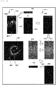
Fig. 4] Fig. 4 is a schematic view for describing an artifact reduction process according to the embodiment. - [
Fig. 5] Fig. 5 is a schematic view for describing an artifact reduction process according to the embodiment. - [
Fig. 6] Fig. 6 is a flowchart illustrating an artifact reduction process according to the embodiment. -
Fig. 1 is a view illustrating an external configuration of an imaging apparatus fordiagnosis 100 according to an embodiment of the present invention, which uses OCT (in the present embodiment, SS-OCT). As illustrated inFig. 1 , the imaging apparatus fordiagnosis 100 serving as a tomographic image forming apparatus includes aprobe 101, a scanner and pull-back unit 102, and anoperation control device 103. The scanner and pull-back unit 102 and theoperation control device 103 are connected to each other via aconnector 105 by acable 104 which accommodates a signal line and an optical fiber. - The
probe 101 is directly inserted into a blood vessel. A catheter which accommodates an imaging core is inserted into theprobe 101. The imaging core includes an optical transceiver which continuously transmits transmitted light (measurement light) to the inside of the blood vessel and which continuously receives reflected light from the inside of the blood vessel. The imaging apparatus fordiagnosis 100 measures a state inside the blood vessel by using the imaging core. Theprobe 101 is detachably attached to thepullback unit 102, and thepullback unit 102 drives an embedded motor, thereby regulating the imaging core inside a catheter inserted into theprobe 101, when the imaging core performs an operation in an axial direction and an operation in a rotation direction inside the blood vessel. In addition, thepullback unit 102 acquires the reflected light received by the optical transceiver inside the imaging core, and transmits the reflected light to theoperation control device 103. - In order to perform measurement, the
operation control device 103 is provided with a function for inputting various setting values and a function for displaying various blood vessel images after processing optical interference data obtained by measurement. In theoperation control device 103, thereference numeral 111 represents a main body control unit. The mainbody control unit 111 generates interference light data by causing the reflected light from the imaging core to interfere with reference light obtained by separating light from a light source. Based on the interference light data, the mainbody control unit 111 generates the line data, and generates a tomographic image (blood vessel cross-sectional image) based on light interference through interpolation processing. - The reference numeral 111-1 represents a printer & DVD recorder, which prints a processing result in the main
body control unit 111 or stores the processing result as data. Thereference numeral 112 represents an operation panel. A user inputs various setting values and instructions via theoperation panel 112. Thereference numeral 113 represents an LCD monitor serving as a display device. TheLCD monitor 113 displays various cross-sectional images generated by the mainbody control unit 111. Thereference numeral 114 represents a mouse serving as a pointing device (coordinate input device). - Next, a functional configuration of the imaging apparatus for
diagnosis 100 will be described.Fig. 2 is a block configuration diagram of the imaging apparatus fordiagnosis 100. Hereinafter, referring to the drawing, a functional configuration of wavelength swept OCT (SS-OCT) will be described. - In
Fig. 2 , thereference numeral 201 represents a signal processing unit which performs overall control on the imaging apparatus for diagnosis, and is configured to have some circuits including a microprocessor. Thereference numeral 210 represents a non-volatile storage device represented by a hard disk, and stores various programs or data files to be executed by thesignal processing unit 201. Thereference numeral 202 represents a memory (RAM) disposed inside thesignal processing unit 201. The microprocessor (computer) of thesignal processing unit 201 executes a program stored in thememory 202, thereby performing a tomographic image generation process including reduction / removal of an artifact (to be described later). Thereference numeral 203 represents a wavelength swept light source, and represents a light source which repeatedly generates light having a wavelength varying within a preset range along a time axis. - The light output from the wavelength swept
light source 203 is incident on one end of a firstsingle mode fiber 271, and is transmitted toward a distal side. The firstsingle mode fiber 271 is optically coupled to a fourthsingle mode fiber 275 in anoptical fiber coupler 272 located in an intermediate portion. In theoptical fiber coupler 272, the light output from the wavelength sweptlight source 203 is divided into the measurement light and the reference light. The reference light proceeds to the fourthsingle mode fiber 275. The light (measurement light) which is incident on the firstsingle mode fiber 271 and which is emitted to the distal side by theoptical fiber coupler 272 is guided to a secondsingle mode fiber 273 via theconnector 105. The other end of the secondsingle mode fiber 273 is connected to an optical rotary joint 230 inside thepullback unit 102. - On the other hand, the
probe 101 has anadapter 101a for being connected to thepullback unit 102. Then, theprobe 101 is connected to thepullback unit 102 by theadapter 101a, thereby allowing theprobe 101 to be stably held by thepullback unit 102. Furthermore, an end portion of a thirdsingle mode fiber 274 which is rotatably accommodated inside theprobe 101 is connected to the optical rotary joint 230. As a result, the secondsingle mode fiber 273 and the thirdsingle mode fiber 274 are optically coupled to each other. Animaging core 250 having the mounted optical transceiver which emits the light in a direction substantially orthogonal to a rotation axis and which receives the reflected light is disposed in the other end (leading portion side of the probe 101) of the thirdsingle mode fiber 274. - As a result of the above-described configuration, the light emitted by the wavelength swept
light source 203 is guided to theimaging core 250 disposed in an end portion of the thirdsingle mode fiber 274 via the firstsingle mode fiber 271, the secondsingle mode fiber 273, and the thirdsingle mode fiber 274. The optical transceiver of theimaging core 250 emits the light in a direction substantially orthogonal to an axis of the fiber, and emits the measurement light to an imaging target. The optical transceiver receives the reflected light. The received reflected light is reversely guided in turn, and is caused to return to theoperation control device 103. - A
rotary drive device 240 has aradial scanning motor 241 which rotationally drives the imaging core and the thirdsingle mode fiber 274, anencoder unit 242 which is used for rotary drive control, and alinear drive unit 243 for linearly driving (pullback) the imaging core and the thirdsingle mode fiber 274. - On the other hand, an optical path
length changing mechanism 220 which fine-adjusts an optical path length of the reference light is disposed in an end portion opposite to the fourthsingle mode fiber 275 coupled to theoptical fiber coupler 272. The optical pathlength changing mechanism 220 functions as optical path length changing means for changing the optical path length corresponding to length variations so that the length variations of therespective probes 101 can be absorbed in a case of replacing theprobes 101. Therefore, acollimator lens 225 located in an end portion of the fourthsingle mode fiber 275 is disposed on a one-axis stage 224 which is movable in a direction indicated by anarrow 226, that is, an optical axis direction thereof. - Furthermore, the one-
axis stage 224 is also provided with a function as adjusting means for adjusting offset. For example, even in a case where the distal end of theprobe 101 is not in close contact with a biological tissue surface, the one-axis stage finely changes the optical path length. In this manner, it is possible to set a state where the reflected light from a position of the biological tissue surface is interfered with the reference light. - The optical path length is fine-adjusted in the one-
axis stage 224. The light reflected on amirror 223 via agrating 221 and alens 222 is guided again to the fourthsingle mode fiber 275, and is mixed with the light obtained from the secondsingle mode fiber 273 side, in theoptical fiber coupler 272. In this manner, the light is received as the interference light by aphotodiode 204. The interference light received in this way by thephotodiode 204 is photo-electrically converted, is amplified by anamplifier 205, and is input to ademodulator 206. Thedemodulator 206 performs a demodulation process for extracting only a signal component of the interfered light, and an output thereof is input to an A/D converter 207 as an interference light signal. - In the A/
D converter 207, the interference light signal is sampled as many as 2,048 points at 90 MHz, for example, thereby generating one line digital data (interference light data). A sampling frequency is set to 90 MHz on the assumption that approximately 90% of a cycle (25 µsec) of wavelength sweeping is extracted as digital data of 2, 048 points in a case where a repeated frequency of the wavelength sweeping is set to 40 kHz. However, a configuration is not particularly limited thereto. - The interference light data in line units, which is generated in the A/
D converter 207, is input to thesignal processing unit 201, and is temporarily stored in thememory 202. Then, in thesignal processing unit 201, the interference light data is subjected to frequency decomposition by means of FFT (fast Fourier transform), data in a depth direction (hereinafter, referred to as A-line data) is generated, and the data is subjected to coordinate-convert. In this manner, an optical cross-sectional image at each position inside the blood vessel is built, and is output to anLCD monitor 113 at a predetermined frame rate. In this way, a cross-sectional image of an imaging target is generated, based on light intensity of the interference light obtained from the reflected light and the reference light. Thesignal processing unit 201 is further connected to a drive unit for opticalpath length adjustment 209 and acommunication unit 208. Thesignal processing unit 201 performs control on a position of the one-axis stage 224 via the drive unit for optical path length adjustment 209 (optical path length control). - The
communication unit 208 has some drive circuits embedded therein, and communicates with thepullback unit 102 under the control of thesignal processing unit 201. Specifically, thecommunication unit 208 supplies a drive signal to theradial scanning motor 241 in order to cause the optical rotary joint 230 inside thepullback unit 102 to rotate the thirdsingle mode fiber 274, receives a signal from theencoder unit 242 in order to detect a rotation position of the radial motor, and supplies a drive signal to thelinear drive unit 243 in order to pull the thirdsingle mode fiber 274 at predetermined speed. - The above-described process in the
signal processing unit 201 is also realized by causing a computer to execute a predetermined program. - In the above-described configuration, if the
probe 101 is located at a diagnosis target blood vessel position (coronary artery) of a patient, a transparent flush liquid is delivered toward the distal end of theprobe 101 by a user's operation, and is discharged into the blood vessel through a guiding catheter. The reason is to exclude the blood influence. Then, if a user inputs an instruction to start scanning, thesignal processing unit 201 drives the wavelength sweptlight source 203 so as to drive theradial scanning motor 241 and the linear drive unit 243 (hereinafter, a process of light emitting and light receiving by driving theradial scanning motor 241 and thelinear drive unit 243 is referred to as scanning). As a result, wavelength swept light from the wavelength sweptlight source 203 is supplied to theimaging core 250 through the above-described route. In this case, while being rotated, theimaging core 250 located at a distal position of theprobe 101 is moved along the rotation axis. Accordingly, while being rotated and moved along a blood vessel axis, theimaging core 250 emits the light to the vascular lumen surface, and receives the reflected light. - Here, a process required for generating one sheet of the tomographic images (optical cross-sectional images) will be briefly described with reference to
Fig. 3 . The drawing is a view for describing a reconstructing process of the cross-sectional image of avascular lumen surface 301 on which theimaging core 250 is located. While theimaging core 250 is rotated once (360 degrees), the measurement light is transmitted and received multiple times. If the light is transmitted and received once, it is possible to obtain data of one line in the light emitting direction. Therefore, for example, during the single rotation, the light is transmitted and received 512 times. Accordingly, it is possible to obtain data of 512 lines extending radially from arotation center 302. In the data of 512 lines, the lines are dense in the vicinity of therotation center 302, and the lines become sparse as a distance is away from therotation center 302. Therefore, known interpolation processing is performed to generate a pixel in an empty space between the respective lines, thereby generating a two-dimensional cross-sectional image which is visible to humans. A center position of the two-dimensional cross-sectional image is coincident with therotation center 302 of theimaging core 250. However, it is to be noted that the center position is not a center position of the blood vessel cross section. In addition, the light is reflected on a lens surface of theimaging core 250 or a surface of the catheter. Accordingly, as illustrated by thereference numeral 303, some circles concentric to therotation center 302 are generated. - Next, a process for reducing the artifact on the tomographic image obtained as described above will be described with reference to
Figs. 4 to 6 .Figs. 4 and5 are schematic views for describing the artifact reduction process according to the embodiment.Fig. 6 is a flowchart illustrating the artifact reduction process according to the embodiment, which is realized by causing the microprocessor (computer) of thesignal processing unit 201 to execute a program stored in thememory 202. A case will be described where atomographic image 400 is obtained according to the above-described configuration. Aradial artifact 401 caused by the reflection of the stent strut appears on thetomographic image 400. In addition, a concentric ring-shapedartifact 402 appears in a central portion on thetomographic image 400 due to the reflection on the lens surface, an inner surface, or an outer surface of the catheter sheath or an optical system. In the artifact removal process according to the present embodiment, thisradial artifact 401 is effectively reduced or removed. - As described with reference to
Fig. 3 , thetomographic image 400 is obtained by radially arranging the A-line data around therotation center 302. As described above with reference toFig. 3 , the A-line data configures the tomographic image obtained by rotating the light emitted from theimaging core 250 360 degrees through the optical coherence tomography, and is obtained in each emitting direction. In the present embodiment, the artifact is reduced using anoriginal image 410 obtained by arranging this A-line data in a horizontal axis direction (x-axis direction) as a rotary angle. Therefore, first, in Step S601, thesignal processing unit 201 arranges the A-line data, which are obtained in the emitting directions, in the horizontal axis direction (x-axis direction) as the rotary angle, thereby obtaining theoriginal image 410. A vertical axis direction (y-axis direction) on theoriginal image 410 is coincident with the direction of the A-line data, and an upper side is coincident with therotation center 302 of each A-line data. As illustrated in theoriginal image 410, the concentric ring-shapedartifact 402 on thetomographic image 400 becomes aline 4021 in the x-axis direction, and theartifact 401 extending radially on thetomographic image 400 becomes anartifact 4011 extending in the y-axis direction. - The subsequent process in Steps S602 to S606 is performed in order to remove an image (that is, the line 4021) of the lens surface or the catheter sheath, which appears substantially concentrically on the
tomographic image 400. This reduces the influence of theline 4021 for the removal process of the artifact 4011 (to be described later). First, in Step S602, thesignal processing unit 201 selects a predetermined region on the rotation center side of the A-line data in theoriginal image 410 on which the A-line data is arranged in the horizontal axis direction. The predetermined region is a region where theline 4021 is present on the original image 410 (hereinafter, this region is referred to as a sheath region 411). Thesheath region 411 may be selected (extracted) from theoriginal image 410 so that a user designates a boundary of thesheath region 411 while observing theoriginal image 410. Alternatively, the positions of the inner wall and the outer wall of the catheter sheath can be, to some extent, determined from the lens surface in the imaging core. Accordingly, a region within a predetermined distance from the rotation center may be extracted as thesheath region 411 so as to automatically include the tube walls of the catheter sheath. - Next, in Step S602, the
signal processing unit 201 cuts out an image of thesheath region 411 from theoriginal image 410, and generates asheath image 413 by connecting the image to ablack image 412 having the same size as that of anon-sheath region 421 which is an image region other than thesheath region 411. Thesheath image 413 may be generated and acquired in such a way that the region other than the sheath region 411 (non-sheath region 421 which is the region other than the above-described predetermined region) on theoriginal image 410 is filled with a black color (lowest brightness value). Alternatively, an image of thesheath region 411 may be cut out so as to be used for the following process as thesheath image 413. - Next, in Step S603, the
signal processing unit 201 converts thesheath image 413 which is a spatial domain image into afrequency domain image 414. As a method of converting the spatial image into the frequency domain image, it is possible to use a known converting method such as two-dimensional Fourier transform, cosine transform, and sine transform. Thefrequency domain image 414 illustrated inFig. 4 is obtained through logarithmic representation of amplitude in the two-dimensional Fourier transform, and is shifted so that a DC component is an image center. On thisimage 414, a u-axis direction represents frequency distribution in the x-axis direction on thesheath image 413, and a v-axis direction represents frequency distribution in the y-axis direction on thesheath image 413. An image extending in the x-axis direction on theoriginal image 410 in the spatial domain as theline 4021 has zero or approximate zero frequency component in the x-axis direction, and is mainly expressed by the frequency component in the y-axis direction. Therefore, theline 4021 appears as animage 418 extending in the v-axis direction near u=0, on thefrequency domain image 414. - In Step S604, the
signal processing unit 201 performs a process for removing or reducing the sheath image extending in the x-axis direction. Here, in order to relatively reduce the amplitude of the DC component which shows a zero frequency on theimage 414, compared to other components, the following process is performed, for example. On theimage 414, thesignal processing unit 201 performs a filtering process in which values of some or all of the lines u=0 which show the DC component (zero frequency component) in the u-axis direction or values in the vicinity of the lines (-Δu≤u≤Δu) decrease to zero or smaller, or gradually approximate to zero, thereby generating a processedimage 415. Subsequently, in Step S605, thesignal processing unit 201 performs a process for returning the processedimage 415 to thespatial domain image 416. For example, if the processedimage 415 is an amplitude image in the frequency space which is obtained through the Fourier transform process, the processedimage 415 is subjected to the inverse Fourier transform in conjunction with a phase image. In this manner, thespatial domain image 416 is obtained. In some cases, theartifact 401 extending radially extends into thesheath region 411. Therefore, in order to remove the artifact, filtering may be further performed in which the zero frequency component (line of v=0) in the horizontal axis direction decreases to zero or smaller, or gradually approximates to zero. - Subsequently, in Step S606, the
signal processing unit 201 cuts out a region corresponding to thesheath region 411 as animage 417 from theimage 416, and replaces thesheath region 411 of theoriginal image 410 with theimage 417. In this way, animage 422 is obtained in which the sheath image is removed / reduced from theoriginal image 410. For example, theimage 417 cut out from theimage 416 and the image of thenon-sheath region 421 obtained from theoriginal image 410 are connected to each other, thereby obtaining the image 422 (partially replaced original image) in which the sheath image is removed from theoriginal image 410. A method of generating theimage 422 is not limited to the above-described one. For example, theimage 422 may be generated in such a way that a position corresponding to thesheath region 411 of theoriginal image 410 is overwritten with theimage 417. - Subsequently, in Steps S607 to S609, the removal process is performed on the artifact 401 (4011) extending radially. First, in Step S607, the
signal processing unit 201 converts theimage 422 in which the sheath image is removed / reduced (partially replaced original image), into afrequency domain image 423. The process in Step S607 is similar to the process in Step S603. As a method of converting the spatial domain image into the frequency domain image, it is possible to use a known converting method such as two-dimensional Fourier transform, cosine transform, and sine transform. - As described above, the
artifact 401 appears as an image (artifact 4011) extending long in the vertical direction (y-axis direction) on theimage 422. Therefore, in Step S608, thesignal processing unit 201 removes or reduces the artifact in the vertical direction on theimage 422. Here, in order to relatively reduce the amplitude of the DC component which shows a zero frequency on theimage 423, compared to other components, the following process is performed, for example. On thefrequency domain image 423, the artifact extending in the vertical direction on theimage 422 appears as animage 426 extending in the u-axis direction near v=0. Therefore, in the process for removing or reducing the DC component in Step S608, thesignal processing unit 201 performs a filtering process in which values of some or all of the lines v=0 which show the DC component (zero frequency component) corresponding to the artifact in the y-axis direction on theimage 422 or values in the vicinity of the lines (-Δv≤v≤Δv) decrease to zero or smaller, or gradually approximate to zero, thereby generating a processed image 424. - In some cases, a ring-shaped artifact appears on the
tomographic image 400 due to the reflection on the lens surface, an inner surface, or an outer surface of the catheter sheath or an optical system in the imaging core. In a case where filtering is performed on u=0 or the vicinity values concurrently with the process on the line v=0, the process is also concurrently performed on the ring-shaped artifact. However, the process may not necessarily be performed concurrently. Therefore, in order to remove the artifact, filtering may be further performed in which a value of some or all of the lines u=0 which show the DC component (zero frequency component) in the u-axis direction or values in the vicinity of the lines (-Δu≤u≤Δu) decrease to zero or smaller, or gradually approximate to zero. In addition, another filtering may be performed so as to remove the noise. - Subsequently, in Step S609, the processed image 424 which is the frequency domain image is converted into a spatial image. For example, if the processed
image 415 is an amplitude image in the frequency space which is obtained through the Fourier transform, the processedimage 415 is subjected to the inverse Fourier transform in conjunction with a phase image. In this manner, aspatial domain image 425 is obtained. Then, in Step S610, thesignal processing unit 201 performs coordinate-convert on theimage 425, thereby generating atomographic image 430. That is, thesignal processing unit 201 radially re-arranges the A-line data for the respective rotation positions (θ) configuring theimage 425, and performs interpolating between lines, thereby generating thetomographic image 430. - The
tomographic image 430 can be obtained in which the artifact is removed or reduced as described above. However, in some cases, noise is generated on thetomographic image 430 through the process for the above-described frequency domain image. Therefore, in Step S611, a noise removal process is further performed on thetomographic image 430. For example, this noise removal process can be realized by applying a known filter such as a Gaussian filter, a local average filter, and a median filter to thetomographic image 430 in the spatial domain. Alternatively, a threshold process using a brightness threshold and an area threshold may be performed. During the threshold process, in a case where thetomographic image 430 is binarized (in black and white) using the brightness threshold, adjacent white pixels are united into one. In a case where an area thereof is equal to or smaller than the area threshold, a process for deleting the united pixels (black coloring) is performed. For example, as the brightness threshold, a value of 5% to 30% (more preferably 5% to 20%) of the upper limit brightness value is used. For example, as the area threshold, 0.006 mm2 (more preferably 0.004 mm2) is used. - The filtering process and the threshold process which are known may be combined with each other. During the threshold process, any one or both of the brightness threshold and the area threshold may be used. In addition, in the spatial domain, the known filtering process or the threshold process is performed on the
tomographic image 430. However, without being limited thereto, the known filtering process or the threshold process may be performed on theimage 425 obtained before the coordinate-convert. In addition, one of the filtering process and the threshold process may be performed before the coordinate-convert, and the other may be performed after the coordinate-convert. - In addition, during the noise removal process in Step S611, the
tomographic image 430 may be converted into the frequency domain image. A predetermined process may be performed on the frequency domain image, and the processed image may be returned to the spatial domain image. In this manner, the noise may be removed. For example, the predetermined process performed on the frequency domain image includes using a high-pass filter, particularly, a filter for decreasing the DC component to zero or smaller or for causing the DC component to gradually approximate to zero, or a low-pass filter. In addition, the process in the above-described spatial domain and the process in the frequency domain may be combined with each other. Furthermore, the above-described threshold process may be performed on the frequency domain image. - In Steps S604 and S608, the following filter may be used for the amplitude image in the frequency domain. That is, the filter has a distribution in which a center of a region, which has a predetermined width from a line extending in a direction in which the vertical axis or horizontal axis DC component is arranged, is decreased to zero or smaller or gradually approximated to zero, and both ends of the predetermined width (for example, -Δu to Δu or -Δv to Δv) are gradually approximated to original values.
- In addition, in the filtering performed on the image obtained by being converted into the frequency domain, without being limited to the above-described filtering process, for example, a known filtering process using a Wiener filter or a high boost filter may be performed.
- Various filtering processes are performed. However, for example, in a case where the filtering is performed in order to decrease the DC component to zero in the frequency domain, the
tomographic image 430 or thetomographic image 431 which is finally generated becomes darker than the image generated without removing the artifact. Accordingly, brightness correction may be performed concurrently with or after the filtering. The brightness correction may be performed in the frequency domain, or may be performed in the spatial domain. In addition, the brightness correction may be performed after each filtering process, and may be performed only after the final filtering process. The number or the procedure of the brightness correction processes do not matter. - In addition, for example, the brightness correction may be performed using a tone curve. For example, in a case where the brightness correction is performed in the frequency domain, the maximum value of the amplitude image may be stored in advance. The tone curve may be set so that the maximum value obtained after the filtering is performed on the DC component is the maximum value before the filtering. Without being limited to a linear shape, the tone curve may not be the linear shape. Furthermore, the tone curve may not pass through an origin.
- In addition, even in a case where the brightness correction is performed in the spatial domain, the brightness correction may be performed similarly to the case where the brightness correction is performed in the frequency domain. However, in the brightness correction performed in the spatial domain, without being limited to the maximum value, a tone curve may be set so that a change in the brightness value of a certain interest point is close to zero. In this case, the interest point may be set at multiple locations. The tone curve may be subjected to least square approximate through polynomial expression. The interest point may be set by detecting a characteristic on an image such as the stent strut, maybe fixed in advance, or may be manually set. In addition, the interest point may be set in combination thereof.
- In addition, as the
original image 410, the above-described embodiment employs an image obtained by arranging the A-line data for generating one tomographic image in the horizontal axis direction (x-axis direction) as the rotary angle, that is, an image obtained by arranging the A-line data corresponding to 360 degrees. However, a method according to the present embodiment is not limited thereto. That is, the A-line data configuring theoriginal image 410 may be larger or smaller than 360 degrees. However, when the tomographic image is prepared in Step S610, the A-line data needs to be adjusted to line data corresponding to one tomographic image (360 degrees). - In addition, in the above-described embodiment, a case of OCT/OFDI which can obtain a cross-sectional image of the blood vessel while rotating in the vascular lumen has been described. However, without being limited thereto, as a method according to the present embodiment, substantially linear or substantially plane scanning, or successive scanning on a fixed point may be used. In this case, Step S610 is omitted.
- As described above, according to the above-described embodiment, a radial artifact or a ring-shaped artifact which appears on the tomographic image by using the optical coherence tomography is removed or reduced, thereby providing the tomographic image which facilitates diagnosis. In addition, since the tomographic image is used, automatic detection of the stent strut can be more accurately performed. In addition, in the above-described embodiment, a case has been described where the microprocessor (computer) of the
signal processing unit 201 executes the program stored in thememory 202 so as to realize the tomographic image generation process including the reduction / removal of the artifact and so as to output the generated image to theLCD monitor 113 for display. However, without being limited thereto, the tomographic image may be generated as image data. The generation process may be progressively performed by executing the program without displaying the image. In this case, only an image whose artifact is completely reduced / removed is output to and displayed on theLCD monitor 113. In addition, without the image whose artifact is completely reduced / removed being output to and displayed on theLCD monitor 113, the data may be stored as the image data in thestorage device 210. That is, it is apparent that the image described in the above-described embodiment includes two meanings of both an image as display data output to and displayed on theLCD monitor 113 and data sequence as non-display data which is not displayed on theLCD monitor 113. - Without being limited to the above-described embodiments, the present invention can be changed and modified in various ways without departing from the spirit and the scope of the present invention. Therefore, in order to officially announce the scope of the present invention, claims are appended as follows.
- This application claims benefit of Japanese Patent Application No.
2014-197500 filed on September 26, 2014
Claims (17)
- A tomographic image forming apparatus which divides light output from a light source inside the apparatus into measurement light and reference light, and which generates a cross-sectional image of an imaging target based on light intensity of interference light obtained from reflected light obtained by emitting the measurement light to the imaging target and the reference light, comprising:first generation means for generating a second image by converting a first image in which line data generated based on the light intensity and having information in a direction of a first axis which serves as a depth direction of the imaging target is arranged in a direction of a second axis, into a frequency domain;first reduction means for removing or reducing an artifact by performing filtering on the second image; andsecond generation means for generating a third image by inversely converting the second image processed by the first reduction means, into a spatial domain.
- The tomographic image forming apparatus according to Claim 1,
wherein the first generation means converts the first image into the second image by Fourier transform, cosine transform, or sine transform. - The tomographic image forming apparatus according to Claim 1 or 2,
wherein the first reduction means relatively reduces an amplitude of a DC component which shows a zero frequency on the second image, compared to other components. - The tomographic image forming apparatus according to any one of Claims 1 to 3,
wherein the first reduction means relatively reduces an amplitude of a DC component, which shows a zero frequency in at least one axial direction on the first image, on the second image, compared to other components. - The tomographic image forming apparatus according to any one of Claims 1 to 3,
wherein the first reduction means relatively reduces an amplitude of a frequency component, which is in a region having a predetermined width in an axis direction corresponding to the first axis or the second axis of the first image, on the second image, compared to other components. - The tomographic image forming apparatus according to Claim 4 or 5,
wherein the first reduction means relatively reduces an amplitude of a frequency component, which is in a region having a predetermined width from the first axis or the second axis DC component of the first image, on the second image, compared to other components. - The tomographic image forming apparatus according to Claim 6,
wherein the first reduction means uses a filter having a distribution in which amplitudes in both ends of the predetermined width from the DC component are approximated to original values. - The tomographic image forming apparatus according to any one of Claims 3 to 7,
wherein the first reduction means decreases the amplitude of the DC component to zero or smaller, or gradually approximates the amplitude of the DC component to zero. - The tomographic image forming apparatus according to any one of Claims 1 to 8,
wherein the second generation means further includes means for applying a filter to the third image in the spatial domain, or for reducing noise through a threshold process. - The tomographic image forming apparatus according to any one of Claims 1 to 9,
wherein the second generation means further includes means for reducing noise on the third image by converting the third image into a frequency domain and applying a filter thereto or performing a threshold process thereon. - The tomographic image forming apparatus according to any one of Claims 1 to 10,
wherein the first generation means further includes:selection means for selecting a predetermined region of an original image in which the line data is arranged in the direction of the second axis;second reduction means for relatively reducing an amplitude of a DC component, which shows a zero frequency in the direction of the second axis on the original image, on an image obtained by converting the image in the predetermined region into a frequency domain, compared to other components; andreplacement means for replacing the predetermined region of the original image with an image obtained by inversely converting the image processed by the second reduction means into an image in the spatial domain,wherein the image obtained by the replacement means is the first image. - The tomographic image forming apparatus according to Claim 11,
wherein the image in the predetermined region in the second reduction means is an image where a region other than the predetermined region of the original image is set to have the lowest brightness value, and
wherein the replacement means extracts the predetermined region from the image obtained by inversely converting the image processed by the second reduction means into the spatial domain, and replaces the image in the predetermined region of the original image. - The tomographic image forming apparatus according to Claim 11 or 12,
wherein the selection means selects a region within a predetermined distance from the shallowest position of the first axis on the original image, as the predetermined region. - The tomographic image forming apparatus according to any one of Claims 11 to 13,
wherein the selection means selects a region designated by a user as the predetermined region. - The tomographic image forming apparatus according to any one of Claims 1 to 14,
wherein brightness correction is performed after at least one filtering in the filtering processes performed by the first reduction means. - A control method of a tomographic image forming apparatus which divides light output from a light source inside the apparatus into measurement light and reference light, and which generates a cross-sectional image of an imaging target based on light intensity of interference light obtained from reflected light obtained by emitting the measurement light to the imaging target and the reference light, the control method comprising:a first generation process for generating a second image by converting a first image in which line data generated based on the light intensity and having information in a direction of a first axis which serves as a depth direction of the imaging target is arranged in a direction of a second axis, into a frequency domain;a first reduction process for removing or reducing an artifact by performing filtering on the second image; anda second generation process for generating a third image by inversely converting the second image processed in the first reduction process, into a spatial domain.
- A program which causes a computer to execute each process of the control method according to Claim 16.
Applications Claiming Priority (2)
| Application Number | Priority Date | Filing Date | Title |
|---|---|---|---|
| JP2014197500 | 2014-09-26 | ||
| PCT/JP2015/077172 WO2016047773A1 (en) | 2014-09-26 | 2015-09-25 | Tomographic image formation device and control method |
Publications (3)
| Publication Number | Publication Date |
|---|---|
| EP3199085A1 true EP3199085A1 (en) | 2017-08-02 |
| EP3199085A4 EP3199085A4 (en) | 2018-07-11 |
| EP3199085B1 EP3199085B1 (en) | 2019-08-07 |
Family
ID=55581289
Family Applications (1)
| Application Number | Title | Priority Date | Filing Date |
|---|---|---|---|
| EP15843233.6A Active EP3199085B1 (en) | 2014-09-26 | 2015-09-25 | Tomographic image formation device and control method |
Country Status (4)
| Country | Link |
|---|---|
| US (1) | US10898140B2 (en) |
| EP (1) | EP3199085B1 (en) |
| JP (1) | JP6587624B2 (en) |
| WO (1) | WO2016047773A1 (en) |
Families Citing this family (8)
| Publication number | Priority date | Publication date | Assignee | Title |
|---|---|---|---|---|
| WO2011046903A2 (en) | 2009-10-12 | 2011-04-21 | Moore Thomas C | Intravascular ultrasound system for co-registered imaging |
| US10909661B2 (en) * | 2015-10-08 | 2021-02-02 | Acist Medical Systems, Inc. | Systems and methods to reduce near-field artifacts |
| US11369337B2 (en) | 2015-12-11 | 2022-06-28 | Acist Medical Systems, Inc. | Detection of disturbed blood flow |
| WO2019118646A1 (en) * | 2017-12-13 | 2019-06-20 | President And Fellows Of Harvard College | Endoscopic imaging using nanoscale metasurfaces |
| US11024034B2 (en) | 2019-07-02 | 2021-06-01 | Acist Medical Systems, Inc. | Image segmentation confidence determination |
| US11361481B2 (en) * | 2019-09-18 | 2022-06-14 | Topcon Corporation | 3D shadow reduction signal processing method for optical coherence tomography (OCT) images |
| CN111640106A (en) * | 2020-06-02 | 2020-09-08 | 中国医学科学院阜外医院深圳医院(深圳市孙逸仙心血管医院) | A method for converting multimodal medical images based on artificial intelligence |
| WO2022038697A1 (en) * | 2020-08-19 | 2022-02-24 | デラウェーブ株式会社 | Optical tomographic imaging device, and method for processing tomographic images |
Family Cites Families (7)
| Publication number | Priority date | Publication date | Assignee | Title |
|---|---|---|---|---|
| JP5628785B2 (en) | 2009-02-19 | 2014-11-19 | テルモ株式会社 | Diagnostic imaging equipment |
| JP5451485B2 (en) * | 2010-03-29 | 2014-03-26 | テルモ株式会社 | Optical coherence tomography apparatus and method for operating the same |
| JP5755956B2 (en) * | 2011-06-30 | 2015-07-29 | テルモ株式会社 | Optical coherence tomography system |
| JP5450527B2 (en) * | 2011-08-10 | 2014-03-26 | 富士フイルム株式会社 | Endoscope device |
| JP5938926B2 (en) * | 2012-01-31 | 2016-06-22 | 株式会社ニデック | Optical tomography apparatus and noise removal method |
| JP5762995B2 (en) * | 2012-02-28 | 2015-08-12 | 富士フイルム株式会社 | Photoacoustic image generation apparatus and method |
| GB201219761D0 (en) * | 2012-11-02 | 2012-12-19 | Res & Dev Ltd | Method and apparatus for processing the signal in spectral interferometry and method and apparatus for spectral optical coherence tomography |
-
2015
- 2015-09-25 WO PCT/JP2015/077172 patent/WO2016047773A1/en not_active Ceased
- 2015-09-25 JP JP2016550409A patent/JP6587624B2/en active Active
- 2015-09-25 EP EP15843233.6A patent/EP3199085B1/en active Active
-
2017
- 2017-03-23 US US15/466,911 patent/US10898140B2/en active Active
Also Published As
| Publication number | Publication date |
|---|---|
| US20170224286A1 (en) | 2017-08-10 |
| EP3199085A4 (en) | 2018-07-11 |
| US10898140B2 (en) | 2021-01-26 |
| EP3199085B1 (en) | 2019-08-07 |
| WO2016047773A1 (en) | 2016-03-31 |
| JP6587624B2 (en) | 2019-10-09 |
| JPWO2016047773A1 (en) | 2017-07-13 |
Similar Documents
| Publication | Publication Date | Title |
|---|---|---|
| EP3199085B1 (en) | Tomographic image formation device and control method | |
| US11331082B2 (en) | Control device, image diagnosis apparatus, method for processing of control device, and program | |
| US10271818B2 (en) | Image processing apparatus, method of controlling image processing apparatus, program, and storage medium | |
| US8346348B2 (en) | Optical coherent cross-sectional image forming apparatus and control method for controlling such apparatus | |
| JP6523642B2 (en) | Diagnostic imaging device | |
| JP5628785B2 (en) | Diagnostic imaging equipment | |
| JP5508092B2 (en) | Optical diagnostic imaging apparatus and display control method thereof | |
| JP5755956B2 (en) | Optical coherence tomography system | |
| JPWO2014136137A1 (en) | Diagnostic imaging apparatus, information processing apparatus, operating method thereof, program, and computer-readable storage medium | |
| JP6717801B2 (en) | Image diagnostic apparatus and image construction method | |
| WO2012132211A1 (en) | Optical image diagnosis apparatus and image-processing method | |
| US11129592B2 (en) | Image diagnostic apparatus and method and program | |
| JP2018075080A (en) | Image diagnostic apparatus, control method for image diagnostic apparatus, and program | |
| WO2015045352A1 (en) | Diagnostic imaging device | |
| WO2016136579A1 (en) | Imaging diagnostic device, control method, program, and computer readable storage medium therefor | |
| JP2012002598A (en) | Tomographic image processing device and method and optical interference tomographic image diagnostic device | |
| JP2012013432A (en) | Tomographic image processing device and method, and optical coherence tomographic image diagnosing device | |
| JP2023054764A (en) | Fluorescence calibration based on manual lumen detection | |
| JP2023054764A5 (en) | ||
| EP2600137B1 (en) | Optical tomographic imaging system and optical tomographic imaging method | |
| JP5812785B2 (en) | Optical tomographic image processing apparatus and method of operating optical tomographic image processing apparatus | |
| JP6584806B2 (en) | Diagnostic imaging apparatus, control method therefor, program, and computer-readable storage medium | |
| JP2016182303A (en) | Image diagnostic apparatus, control method thereof, program, and computer readable storage medium |
Legal Events
| Date | Code | Title | Description |
|---|---|---|---|
| STAA | Information on the status of an ep patent application or granted ep patent |
Free format text: STATUS: THE INTERNATIONAL PUBLICATION HAS BEEN MADE |
|
| PUAI | Public reference made under article 153(3) epc to a published international application that has entered the european phase |
Free format text: ORIGINAL CODE: 0009012 |
|
| STAA | Information on the status of an ep patent application or granted ep patent |
Free format text: STATUS: REQUEST FOR EXAMINATION WAS MADE |
|
| 17P | Request for examination filed |
Effective date: 20170314 |
|
| AK | Designated contracting states |
Kind code of ref document: A1 Designated state(s): AL AT BE BG CH CY CZ DE DK EE ES FI FR GB GR HR HU IE IS IT LI LT LU LV MC MK MT NL NO PL PT RO RS SE SI SK SM TR |
|
| AX | Request for extension of the european patent |
Extension state: BA ME |
|
| DAV | Request for validation of the european patent (deleted) | ||
| DAX | Request for extension of the european patent (deleted) | ||
| A4 | Supplementary search report drawn up and despatched |
Effective date: 20180611 |
|
| RIC1 | Information provided on ipc code assigned before grant |
Ipc: A61B 1/00 20060101AFI20180605BHEP Ipc: G01B 9/02 20060101ALI20180605BHEP Ipc: A61B 5/00 20060101ALI20180605BHEP Ipc: G01N 21/17 20060101ALI20180605BHEP |
|
| GRAP | Despatch of communication of intention to grant a patent |
Free format text: ORIGINAL CODE: EPIDOSNIGR1 |
|
| STAA | Information on the status of an ep patent application or granted ep patent |
Free format text: STATUS: GRANT OF PATENT IS INTENDED |
|
| RIC1 | Information provided on ipc code assigned before grant |
Ipc: G01N 21/17 20060101ALI20190130BHEP Ipc: A61B 1/00 20060101AFI20190130BHEP Ipc: G01B 9/02 20060101ALI20190130BHEP Ipc: A61B 5/00 20060101ALI20190130BHEP |
|
| INTG | Intention to grant announced |
Effective date: 20190222 |
|
| GRAS | Grant fee paid |
Free format text: ORIGINAL CODE: EPIDOSNIGR3 |
|
| GRAA | (expected) grant |
Free format text: ORIGINAL CODE: 0009210 |
|
| STAA | Information on the status of an ep patent application or granted ep patent |
Free format text: STATUS: THE PATENT HAS BEEN GRANTED |
|
| AK | Designated contracting states |
Kind code of ref document: B1 Designated state(s): AL AT BE BG CH CY CZ DE DK EE ES FI FR GB GR HR HU IE IS IT LI LT LU LV MC MK MT NL NO PL PT RO RS SE SI SK SM TR |
|
| REG | Reference to a national code |
Ref country code: GB Ref legal event code: FG4D |
|
| REG | Reference to a national code |
Ref country code: CH Ref legal event code: EP Ref country code: AT Ref legal event code: REF Ref document number: 1162563 Country of ref document: AT Kind code of ref document: T Effective date: 20190815 |
|
| REG | Reference to a national code |
Ref country code: DE Ref legal event code: R096 Ref document number: 602015035542 Country of ref document: DE |
|
| REG | Reference to a national code |
Ref country code: IE Ref legal event code: FG4D |
|
| REG | Reference to a national code |
Ref country code: NL Ref legal event code: MP Effective date: 20190807 |
|
| REG | Reference to a national code |
Ref country code: LT Ref legal event code: MG4D |
|
| PG25 | Lapsed in a contracting state [announced via postgrant information from national office to epo] |
Ref country code: NL Free format text: LAPSE BECAUSE OF FAILURE TO SUBMIT A TRANSLATION OF THE DESCRIPTION OR TO PAY THE FEE WITHIN THE PRESCRIBED TIME-LIMIT Effective date: 20190807 Ref country code: SE Free format text: LAPSE BECAUSE OF FAILURE TO SUBMIT A TRANSLATION OF THE DESCRIPTION OR TO PAY THE FEE WITHIN THE PRESCRIBED TIME-LIMIT Effective date: 20190807 Ref country code: NO Free format text: LAPSE BECAUSE OF FAILURE TO SUBMIT A TRANSLATION OF THE DESCRIPTION OR TO PAY THE FEE WITHIN THE PRESCRIBED TIME-LIMIT Effective date: 20191107 Ref country code: HR Free format text: LAPSE BECAUSE OF FAILURE TO SUBMIT A TRANSLATION OF THE DESCRIPTION OR TO PAY THE FEE WITHIN THE PRESCRIBED TIME-LIMIT Effective date: 20190807 Ref country code: LT Free format text: LAPSE BECAUSE OF FAILURE TO SUBMIT A TRANSLATION OF THE DESCRIPTION OR TO PAY THE FEE WITHIN THE PRESCRIBED TIME-LIMIT Effective date: 20190807 Ref country code: BG Free format text: LAPSE BECAUSE OF FAILURE TO SUBMIT A TRANSLATION OF THE DESCRIPTION OR TO PAY THE FEE WITHIN THE PRESCRIBED TIME-LIMIT Effective date: 20191107 Ref country code: PT Free format text: LAPSE BECAUSE OF FAILURE TO SUBMIT A TRANSLATION OF THE DESCRIPTION OR TO PAY THE FEE WITHIN THE PRESCRIBED TIME-LIMIT Effective date: 20191209 Ref country code: FI Free format text: LAPSE BECAUSE OF FAILURE TO SUBMIT A TRANSLATION OF THE DESCRIPTION OR TO PAY THE FEE WITHIN THE PRESCRIBED TIME-LIMIT Effective date: 20190807 |
|
| REG | Reference to a national code |
Ref country code: AT Ref legal event code: MK05 Ref document number: 1162563 Country of ref document: AT Kind code of ref document: T Effective date: 20190807 |
|
| PG25 | Lapsed in a contracting state [announced via postgrant information from national office to epo] |
Ref country code: LV Free format text: LAPSE BECAUSE OF FAILURE TO SUBMIT A TRANSLATION OF THE DESCRIPTION OR TO PAY THE FEE WITHIN THE PRESCRIBED TIME-LIMIT Effective date: 20190807 Ref country code: GR Free format text: LAPSE BECAUSE OF FAILURE TO SUBMIT A TRANSLATION OF THE DESCRIPTION OR TO PAY THE FEE WITHIN THE PRESCRIBED TIME-LIMIT Effective date: 20191108 Ref country code: RS Free format text: LAPSE BECAUSE OF FAILURE TO SUBMIT A TRANSLATION OF THE DESCRIPTION OR TO PAY THE FEE WITHIN THE PRESCRIBED TIME-LIMIT Effective date: 20190807 Ref country code: ES Free format text: LAPSE BECAUSE OF FAILURE TO SUBMIT A TRANSLATION OF THE DESCRIPTION OR TO PAY THE FEE WITHIN THE PRESCRIBED TIME-LIMIT Effective date: 20190807 Ref country code: IS Free format text: LAPSE BECAUSE OF FAILURE TO SUBMIT A TRANSLATION OF THE DESCRIPTION OR TO PAY THE FEE WITHIN THE PRESCRIBED TIME-LIMIT Effective date: 20191207 Ref country code: AL Free format text: LAPSE BECAUSE OF FAILURE TO SUBMIT A TRANSLATION OF THE DESCRIPTION OR TO PAY THE FEE WITHIN THE PRESCRIBED TIME-LIMIT Effective date: 20190807 |
|
| PG25 | Lapsed in a contracting state [announced via postgrant information from national office to epo] |
Ref country code: TR Free format text: LAPSE BECAUSE OF FAILURE TO SUBMIT A TRANSLATION OF THE DESCRIPTION OR TO PAY THE FEE WITHIN THE PRESCRIBED TIME-LIMIT Effective date: 20190807 |
|
| PG25 | Lapsed in a contracting state [announced via postgrant information from national office to epo] |
Ref country code: EE Free format text: LAPSE BECAUSE OF FAILURE TO SUBMIT A TRANSLATION OF THE DESCRIPTION OR TO PAY THE FEE WITHIN THE PRESCRIBED TIME-LIMIT Effective date: 20190807 Ref country code: IT Free format text: LAPSE BECAUSE OF FAILURE TO SUBMIT A TRANSLATION OF THE DESCRIPTION OR TO PAY THE FEE WITHIN THE PRESCRIBED TIME-LIMIT Effective date: 20190807 Ref country code: AT Free format text: LAPSE BECAUSE OF FAILURE TO SUBMIT A TRANSLATION OF THE DESCRIPTION OR TO PAY THE FEE WITHIN THE PRESCRIBED TIME-LIMIT Effective date: 20190807 Ref country code: DK Free format text: LAPSE BECAUSE OF FAILURE TO SUBMIT A TRANSLATION OF THE DESCRIPTION OR TO PAY THE FEE WITHIN THE PRESCRIBED TIME-LIMIT Effective date: 20190807 Ref country code: RO Free format text: LAPSE BECAUSE OF FAILURE TO SUBMIT A TRANSLATION OF THE DESCRIPTION OR TO PAY THE FEE WITHIN THE PRESCRIBED TIME-LIMIT Effective date: 20190807 Ref country code: PL Free format text: LAPSE BECAUSE OF FAILURE TO SUBMIT A TRANSLATION OF THE DESCRIPTION OR TO PAY THE FEE WITHIN THE PRESCRIBED TIME-LIMIT Effective date: 20190807 |
|
| PG25 | Lapsed in a contracting state [announced via postgrant information from national office to epo] |
Ref country code: MC Free format text: LAPSE BECAUSE OF FAILURE TO SUBMIT A TRANSLATION OF THE DESCRIPTION OR TO PAY THE FEE WITHIN THE PRESCRIBED TIME-LIMIT Effective date: 20190807 Ref country code: SK Free format text: LAPSE BECAUSE OF FAILURE TO SUBMIT A TRANSLATION OF THE DESCRIPTION OR TO PAY THE FEE WITHIN THE PRESCRIBED TIME-LIMIT Effective date: 20190807 Ref country code: CZ Free format text: LAPSE BECAUSE OF FAILURE TO SUBMIT A TRANSLATION OF THE DESCRIPTION OR TO PAY THE FEE WITHIN THE PRESCRIBED TIME-LIMIT Effective date: 20190807 Ref country code: SM Free format text: LAPSE BECAUSE OF FAILURE TO SUBMIT A TRANSLATION OF THE DESCRIPTION OR TO PAY THE FEE WITHIN THE PRESCRIBED TIME-LIMIT Effective date: 20190807 Ref country code: IS Free format text: LAPSE BECAUSE OF FAILURE TO SUBMIT A TRANSLATION OF THE DESCRIPTION OR TO PAY THE FEE WITHIN THE PRESCRIBED TIME-LIMIT Effective date: 20200224 |
|
| REG | Reference to a national code |
Ref country code: CH Ref legal event code: PL |
|
| REG | Reference to a national code |
Ref country code: DE Ref legal event code: R097 Ref document number: 602015035542 Country of ref document: DE |
|
| PLBE | No opposition filed within time limit |
Free format text: ORIGINAL CODE: 0009261 |
|
| STAA | Information on the status of an ep patent application or granted ep patent |
Free format text: STATUS: NO OPPOSITION FILED WITHIN TIME LIMIT |
|
| PG2D | Information on lapse in contracting state deleted |
Ref country code: IS |
|
| PG25 | Lapsed in a contracting state [announced via postgrant information from national office to epo] |
Ref country code: IE Free format text: LAPSE BECAUSE OF NON-PAYMENT OF DUE FEES Effective date: 20190925 Ref country code: LU Free format text: LAPSE BECAUSE OF NON-PAYMENT OF DUE FEES Effective date: 20190925 Ref country code: CH Free format text: LAPSE BECAUSE OF NON-PAYMENT OF DUE FEES Effective date: 20190930 Ref country code: LI Free format text: LAPSE BECAUSE OF NON-PAYMENT OF DUE FEES Effective date: 20190930 |
|
| 26N | No opposition filed |
Effective date: 20200603 |
|
| REG | Reference to a national code |
Ref country code: BE Ref legal event code: MM Effective date: 20190930 |
|
| PG25 | Lapsed in a contracting state [announced via postgrant information from national office to epo] |
Ref country code: SI Free format text: LAPSE BECAUSE OF FAILURE TO SUBMIT A TRANSLATION OF THE DESCRIPTION OR TO PAY THE FEE WITHIN THE PRESCRIBED TIME-LIMIT Effective date: 20190807 Ref country code: BE Free format text: LAPSE BECAUSE OF NON-PAYMENT OF DUE FEES Effective date: 20190930 |
|
| PG25 | Lapsed in a contracting state [announced via postgrant information from national office to epo] |
Ref country code: CY Free format text: LAPSE BECAUSE OF FAILURE TO SUBMIT A TRANSLATION OF THE DESCRIPTION OR TO PAY THE FEE WITHIN THE PRESCRIBED TIME-LIMIT Effective date: 20190807 |
|
| PG25 | Lapsed in a contracting state [announced via postgrant information from national office to epo] |
Ref country code: MT Free format text: LAPSE BECAUSE OF FAILURE TO SUBMIT A TRANSLATION OF THE DESCRIPTION OR TO PAY THE FEE WITHIN THE PRESCRIBED TIME-LIMIT Effective date: 20190807 Ref country code: HU Free format text: LAPSE BECAUSE OF FAILURE TO SUBMIT A TRANSLATION OF THE DESCRIPTION OR TO PAY THE FEE WITHIN THE PRESCRIBED TIME-LIMIT; INVALID AB INITIO Effective date: 20150925 |
|
| PG25 | Lapsed in a contracting state [announced via postgrant information from national office to epo] |
Ref country code: MK Free format text: LAPSE BECAUSE OF FAILURE TO SUBMIT A TRANSLATION OF THE DESCRIPTION OR TO PAY THE FEE WITHIN THE PRESCRIBED TIME-LIMIT Effective date: 20190807 |
|
| PGFP | Annual fee paid to national office [announced via postgrant information from national office to epo] |
Ref country code: DE Payment date: 20250730 Year of fee payment: 11 |
|
| PGFP | Annual fee paid to national office [announced via postgrant information from national office to epo] |
Ref country code: GB Payment date: 20250807 Year of fee payment: 11 |
|
| PGFP | Annual fee paid to national office [announced via postgrant information from national office to epo] |
Ref country code: FR Payment date: 20250808 Year of fee payment: 11 |